Embed Size (px)
Citation preview
First Edition William H. Hardy, PhD
The Power Measurements Handbook and www.PowerMeasurements.com are a “retirement” project of William H. (Bill) Hardy. Bill is a scientist/entrepreneur who came to the power measurement industry a decade ago after a 30 years career in a variety of instrumentation industries. His focus has been bringing new technologies and capabilities to metering. He is a member of ANSI C12 Main and heads several subcommittees and working groups. Bill continues to teach at a number of meter schools across the country. The Power Measurements website has a library of technical reference materials created by Bill that are available free of charge.
Visit www.PowerMeasurements.com You’ll like what you find there!
About the Author
Power Measurements
Handbook
First Edition
Introduction
Power Measurements Handbook i
Foreword Welcome to the Power Measurements Handbook. For the last decade I’ve been working in the instrumentation sector of the electricity metering industry. When I entered the industry I looked for a reference book for all of those facts that you need on a daily basis. I didn’t really find one. Over the years of work, teaching at meter schools and participating on various ANSI committees I accumulated a ton of information. Now I’ve taken all of those notes and presentations and put them together into a pocket reference.
I hope you will find it the go to resource that finds an honored place in your tool box, glove compartment or desk drawer.
William H. Hardy
Feedback I welcome comments or suggestions for improving this handbook. It is the first edition so it is very likely there may be some mistakes and omissions. Your feedback would be greatly appreciated.
Contact Power Measurements William H. Hardy 6386 Avington Place Gainesville, VA 20155 Email: [email protected]
First edition
Introduction
ii Power Measurements Handbook
Safety Warning Energized electrical circuits present serious safety hazards. All circuits in electricity meters, meter sockets, CT circuits, PT circuits and distribution lines should be considered live hazardous unless verified otherwise. All work on live hazardous circuits should be done only by trained personnel following appropriate safety procedures. CT circuits pose special safety issues. Secondary CT circuits should never be opened if there is any primary current. Opening a CT secondary can result in very high voltage across the secondary terminals. This can lead to explosive arcs and other extremely hazardous conditions. The tables, diagrams and other information in this handbook are intended to be a reference for the most common configurations encountered by metering personnel. Never assume that a circuit conforms to these diagrams unless it has been fully verified. This handbook is not intended as a replacement for proper training and experience. Always be sure to follow all company safety guidelines.
Disclaimer The author assumes no liability with respect to the use of any information included herein whether or not used in accordance with any instructions or recommendations of this handbook.
1st Printing: May 2013 2nd Printing: July 2013 3rd Printing: September 2013 4rd Printing: December 2013 (minor revisions and corrections)
A special note of appreciation to Brad Johnson and his team at Oncor who did an extremely thorough proof reading job of the 3rd Printing enabling the many corrections in this 4th Printing.
© William H. Hardy 2013. All rights reserved.
Introduction
Power Measurements Handbook iii
User’s GuideThis Handbook is intended to serve as a reference for the metering professional. Hopefully it will be useful to a wide range of people—apprentice to senior engineer. I’ve tried to make it interesting as well as informative.
For even more up to date information on electricity metering and all topics related to power measurements, visit www.PowerMeasurements.com. You’ll find a wide variety of resources including:
Complete listings and links to all of the North American meter schools
Copies of presentations presented by Power Measurements
Current status of various metering related standards A compilation of technical information on metering
If you have any material which you think would be useful to the metering community please send a copy to [email protected] so it can be shared with the whole community.
Introduction
iv Power Measurements Handbook
Table of Contents Chapter 1 Basic Electricity ........................................................... 1
A Little History ........................................................................... 1 The Electric Era ........................................................................... 2 Static Electricity .......................................................................... 3 DC Circuits .................................................................................. 4 AC Circuits .................................................................................. 6 Sinusoidal Power Measurement .................................................. 9 Summary: Basic Power Theory ................................................... 11 Vector Diagrams ......................................................................... 12 Power Measurement in the Digital World ................................... 13 Bidirectional Metering ................................................................ 15
Chapter 2 Introduction to Metering ............................................ 17 Metering Standards ..................................................................... 17 Meter Sockets .............................................................................. 19 Meter Forms ................................................................................ 20 Current Transformers .................................................................. 23
Chapter 3 Distribution Services ................................................... 27 Single Phase ................................................................................ 28 Three Phase ................................................................................. 29
Chapter 4 Service Types ............................................................... 31 2-Wire Single Phase .................................................................... 31 3-Wire Single Phase .................................................................... 33 3-Wire Delta ................................................................................ 38 4-Wire Delta ................................................................................ 42 4-Wire Wye ................................................................................. 46
Chapter 5 Testing Metering Installations .................................... 51 Why we test ................................................................................. 51 Testing wiring ............................................................................. 52 Test Current Transformers .......................................................... 53 Testing Potential Transformers ................................................... 54 Testing Meters ............................................................................. 55
Appendix A Non-Blondel Error Analysis .................................... 57 2S, 4S Metering of 1P3W Services ............................................. 57 5S Family 4-Wire Wye ............................................................... 59 6S Family 4-Wire Wye ............................................................... 60 5S Family 4-Wire Delta .............................................................. 61 8S Family 4-Wire Delta .............................................................. 61
Chapter 1: Basic Electrical Theory
Power Measurements Handbook 1
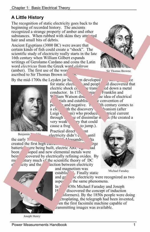
A Little History The recognition of static electricity goes back to the beginning of recorded history. The ancients recognized a strange property of amber and other substances. When rubbed with skins they attracted hair and small bits of debris. Ancient Egyptians (3000 BC) were aware that certain kinds of fish could create a “shock”. The scientific study of electricity really starts in the late 16th century when William Gilbert expands writings of Gerolamo Cardano and coins the Latin word electricus from the Greek word elektron(amber). The first use of the word electricity is ascribed to Sir Thomas Brown in 1646. By the mid-1700s the Leyden jar had been developed as a storage device
for static electricity and people had discovered that electric shock could be transmitted down a metal conductor. In 1752, Benjamin Franklin and William Watson discovered the idea of electrical potentials and established the convention of positive and negative. The 18th century comes to a close with the discovery of galvanism (after Luigi Galvani) who produced electrical current through the use of dissimilar metals (He created a very weak battery that could cause a frog’s leg to jump.).Practical direct current
electricity didn’t come until the early 19th century. In 1900 Alessandro Volta created the first high current battery. By 1809 large batteries were being built, electric ARC lights had been developed and new elemental metals were being discovered by electrically refining oxides. By mid-century much of the scientific theory of DC electricity and the connection between electricity
and magnetism was established. Finally static and galvanic electricity were recognized as two aspects of the same phenomena. In the 1830s Michael Faraday and Joseph Henry discovered the concept of induction (transformers). By the 1850s people were doing electroplating, the telegraph had been invented, even the first facsimile machine capable of transmitting images was available.
Sir Thomas Browne
Benjamin Franklin
Michael Faraday
Joseph Henry
Chapter 1: Basic Electrical Theory
2 Power Measurements Handbook
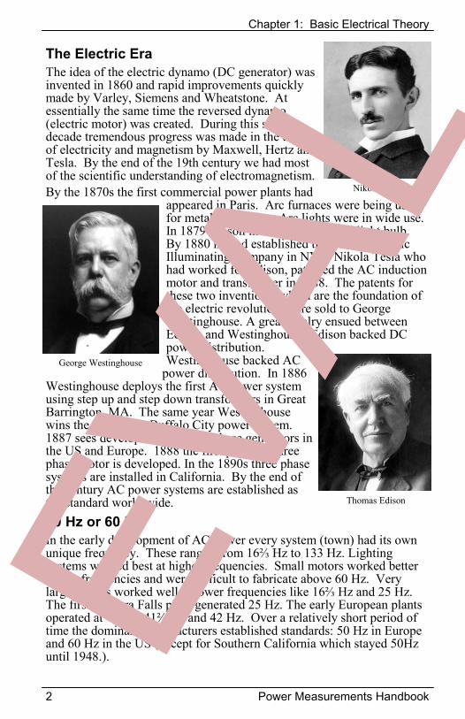
The Electric Era The idea of the electric dynamo (DC generator) was invented in 1860 and rapid improvements quickly made by Varley, Siemens and Wheatstone. At essentially the same time the reversed dynamo (electric motor) was created. During this same decade tremendous progress was made in the theory of electricity and magnetism by Maxwell, Hertz and Tesla. By the end of the 19th century we had most of the scientific understanding of electromagnetism. By the 1870s the first commercial power plants had
appeared in Paris. Arc furnaces were being used for metal production. Arc lights were in wide use. In 1879 Edison invented the electric light bulb. By 1880 he had established the Edison Electric Illuminating Company in NYC. Nikola Tesla who had worked for Edison, patented the AC induction motor and transformer in 1888. The patents for these two inventions, which are the foundation of the electric revolution, were sold to George Westinghouse. A great rivalry ensued between Edison and Westinghouse. Edison backed DC power distribution. Westinghouse backed AC
power distribution. In 1886 Westinghouse deploys the first AC power system using step up and step down transformers in Great Barrington, MA. The same year Westinghouse wins the bid for the Buffalo City power system. 1887 sees development of three phase generators in the US and Europe. 1888 the first practical three phase motor is developed. In the 1890s three phase systems are installed in California. By the end of the century AC power systems are established as the standard world wide. 50 Hz or 60 Hz In the early development of AC power every system (town) had its own unique frequency. These ranged from 16⅔ Hz to 133 Hz. Lighting systems worked best at higher frequencies. Small motors worked better at low frequencies and were difficult to fabricate above 60 Hz. Very large motors worked well at lower frequencies like 16⅔ Hz and 25 Hz. The first Niagara Falls plant generated 25 Hz. The early European plants operated at 40 Hz, 41⅔ Hz and 42 Hz. Over a relatively short period of time the dominant manufacturers established standards: 50 Hz in Europe and 60 Hz in the US (except for Southern California which stayed 50Hz until 1948.).
Nikola Tesla
George Westinghouse
Thomas Edison
Chapter 1: Basic Electrical Theory
Power Measurements Handbook 3
Static Electricity For thousands of years people realized that something strange happened when you rubbed some materials with certain types of cloth. Rub a glass rod with silk and the silk would be attracted to the glass rod. Rub wax with wool and they would attract. Rub two pieces of glass with silk and the two pieces of glass would repel each other. Ben Franklin proposed that the cloths were wiping some invisible fluid from the solids. Thereby creating an excess on the cloth and a deficit on the solid. The terms “negative” and “positive” come from this concept of removing fluid. Little did he know how much confusion would result from an almost correct hypothesis. Only much later did scientists recognize the existence of the real nature of the “fluid”. Subatomic particles called electrons, parts of atoms, compromise the fluid. They get transferred from the wool to the wax by rubbing, just the opposite of Franklin’s conjecture. Facts: The unit for charge is the coulomb.
1 coulomb = 6.2415x10¹⁸ electrons Electrons can move from one point to another. Their ease of movement is known as electric “conductivity”. Materials through which electrons move easily are called “conductors”. Materials through which electrons move with great difficulty are called “insulators”.Facts: The unit of resistance is the ohm (Greek: omega Ω)
Conductivity generally represented by ρ (Greek: rho) has units of ohm∙meters.Resistivity is the inverse of conductivity. It is represented by σ (Greek: sigma). It has units of siemens per meter.
Conductance (shown in parenthesis below) is very large for good conductors and very small for good insulators. Conductors include: silver(6.3x10⁷), copper(6.0x10⁷), gold(4.1x10⁷), aluminum(3.5x10⁷), iron(1.0x10⁷), steel(7.0x10⁶), sea water(4.8) Insulators include: drinking water(5x10⁻² to 5x10⁻⁴), pure water(5.5x10-
6), glass(10-11 to 10-15), rubber(10-14), air(5x10-15), dry wood(10-14 to 10-16), teflon(10-23 to 10-25) The human body is a conductor, a very complicated one. Most of the resistance is skin resistance, while the body core has quite low resistance. If the skin is wet or damaged then the resistance from hand to hand or hand to foot is only a few hundred ohms. Under these conditions severe burns or fatal electrocution is highly likely at utility voltages.
Chapter 1: Basic Electrical Theory
4 Power Measurements Handbook
Direct Current Circuits When there is a potential difference (voltage) between two points, a current (stream of electrons) will flow between the two points if they are connected by a conductor. Ohm’s Law states:
I = V/R Current = Voltage divided by Resistance
The higher the voltage or lower the resistance the more current flows. Kirchoff’s voltage law (KVL) states: The sum of all voltages around a circuit loop is zero. Kirchoff’s current law (KCL) states: The sum of all currents into a node of a circuit is zero.
V = V1 + V2 + V3 I = I1 = I2 = I3 V = (I1/R1) + (I2/R2) + (I3/R3)
Joule’s Law defines the relationship between voltage, current and power. In the simple case of a resistor, power is the heat dissipated.
P = I2R P = E2/R P = VI There are two additional types of linear components that are of common interest: capacitors and inductors. A capacitor stores electric charge. The stored charge produces a voltage across the capacitor given by:
V = q / C where q is the charge in coulombs and C is the capacitance in Farads
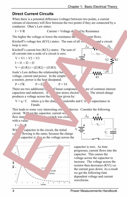
This leads to some very interesting circuit behavior. Consider the following circuit. Without the capacitor, current would flow immediately when the switch was closed with a value:
I = V / R With the capacitor in the circuit, the initial current flowing is the same, because the charge on the capacitor is zero so the voltage across the
capacitor is zero. As time progresses, current flows into the capacitor. This causes the voltage across the capacitor to increase. The voltage across the resistor then decreases (KVL) so the current goes down. As a result we get the following time dependent voltage and current waveforms.
Chapter 1: Basic Electrical Theory
Power Measurements Handbook 5
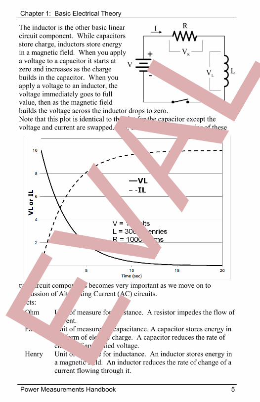
The inductor is the other basic linear circuit component. While capacitors store charge, inductors store energy in a magnetic field. When you apply a voltage to a capacitor it starts at zero and increases as the charge builds in the capacitor. When you apply a voltage to an inductor, the voltage immediately goes to full value, then as the magnetic field builds the voltage across the inductor drops to zero. Note that this plot is identical to the plot for the capacitor except the voltage and current are swapped. The time dependent behavior of these
two circuit components becomes very important as we move on to discussion of Alternating Current (AC) circuits. Facts:
Ohm Unit of measure for resistance. A resistor impedes the flow of current.
Farad Unit of measure for capacitance. A capacitor stores energy in the form of electric charge. A capacitor reduces the rate of change of an applied voltage.
Henry Unit of measure for inductance. An inductor stores energy in a magnetic field. An inductor reduces the rate of change of a current flowing through it.
Chapter 1: Basic Electrical Theory
6 Power Measurements Handbook
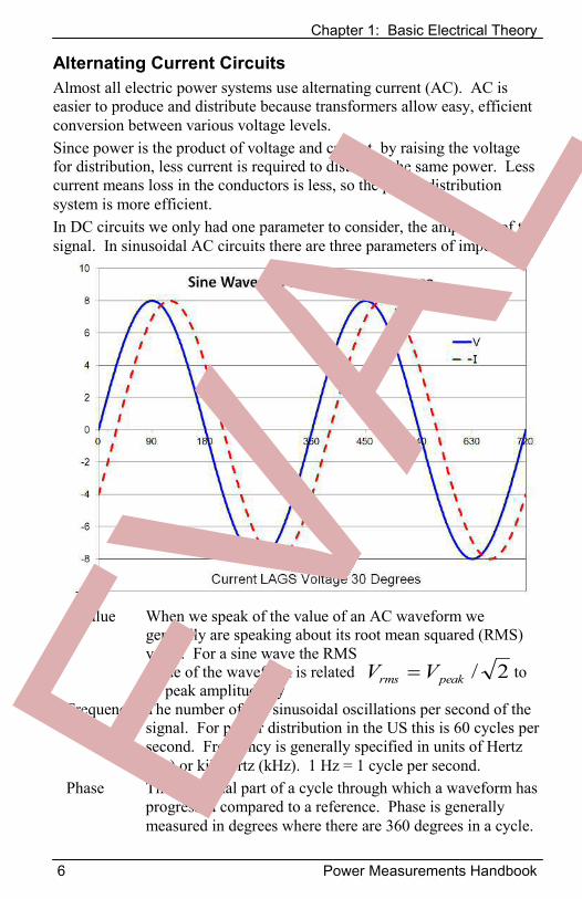
AValue When we speak of the value of an AC waveform we generally are speaking about its root mean squared (RMS) value. For a sine wave the RMS value of the waveform is related to its peak amplitude by
Frequency The number of full sinusoidal oscillations per second of the signal. For power distribution in the US this is 60 cycles per second. Frequency is generally specified in units of Hertz (Hz) or kilohertz (kHz). 1 Hz = 1 cycle per second.
Phase The fractional part of a cycle through which a waveform has progressed compared to a reference. Phase is generally measured in degrees where there are 360 degrees in a cycle.
2/peakrms VV
Alternating Current Circuits Almost all electric power systems use alternating current (AC). AC is easier to produce and distribute because transformers allow easy, efficient conversion between various voltage levels. Since power is the product of voltage and current, by raising the voltage for distribution, less current is required to distribute the same power. Less current means loss in the conductors is less, so the power distribution system is more efficient. In DC circuits we only had one parameter to consider, the amplitude of the signal. In sinusoidal AC circuits there are three parameters of importance:
Chapter 1: Basic Electrical Theory
Power Measurements Handbook 7
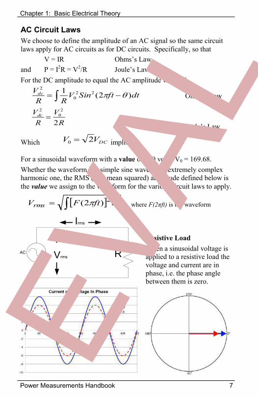
AC Circuit Laws We choose to define the amplitude of an AC signal so the same circuit laws apply for AC circuits as for DC circuits. Specifically, so that V = IR Ohms’s Lawand P = I2R = V2/R Joule’s LawFor the DC amplitude to equal the AC amplitude we need.
Ohms’s Law
Joule’s Law
Which implies
For a sinusoidal waveform with a value of 120 volts, V0 = 169.68. Whether the waveform is a simple sine wave or an extremely complex harmonic one, the RMS (root mean squared) amplitude defined below is the value we assign to the waveform for the various circuit laws to apply.
Resistive Load When a sinusoidal voltage is applied to a resistive load the voltage and current are in phase, i.e. the phase angle between them is zero.
dtftSinVRR
Vdc )2(1 220
2
RV
RVdc
2
20
2
DCVV 20
AC RVrms
Irms
dtftFVrms2)2( where F(2πft) is the waveform
Chapter 1: Basic Electrical Theory
8 Power Measurements Handbook
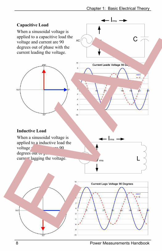
Capacitive Load When a sinusoidal voltage is applied to a capacitive load the voltage and current are 90 degrees out of phase with the current leading the voltage.
Inductive Load When a sinusoidal voltage is applied to a inductive load the voltage and current are 90 degrees out of phase with the current lagging the voltage.
AC CVrms
Irms
AC LVrms
Irms
Chapter 1: Basic Electrical Theory
Power Measurements Handbook 9
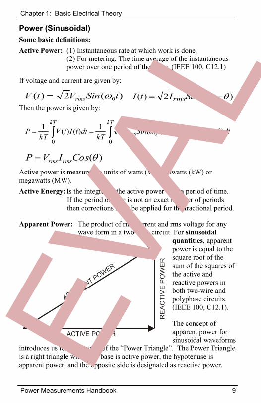
Power (Sinusoidal) Some basic definitions: Active Power: (1) Instantaneous rate at which work is done.
(2) For metering: The time average of the instantaneous power over one period of the wave. (IEEE 100, C12.1)
If voltage and current are given by:
Then the power is given by:
Active power is measured in units of watts (W), kilowatts (kW) or megawatts (MW). Active Energy: Is the integral of the active power over a period of time.
If the period of time is not an exact number of periods then corrections must be applied for the fractional period.
Apparent Power: The product of rms current and rms voltage for any wave form in a two-wire circuit. For sinusoidal
quantities, apparent power is equal to the square root of the sum of the squares of the active and reactive powers in both two-wire and polyphase circuits. (IEEE 100, C12.1).
The concept of apparent power for sinusoidal waveforms
introduces us to the concept of the “Power Triangle”. The Power Triangle is a right triangle where the base is active power, the hypotenuse is apparent power, and the opposite side is designated as reactive power.
)(2)( 0tSinVtV rms )(2)( 0 tSinItI rms
)(CosIVP rmsrms
kT
rmsrms
kTdttSinItSinV
kTdttItV
kTP
000
0
)(2)(21)()(1
Chapter 1: Basic Electrical Theory
10 Power Measurements Handbook
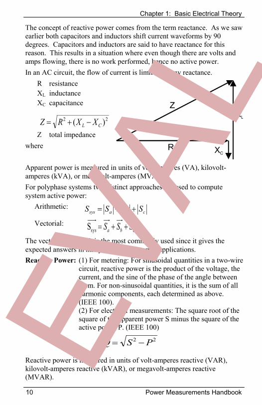
The concept of reactive power comes from the term reactance. As we saw earlier both capacitors and inductors shift current waveforms by 90 degrees. Capacitors and inductors are said to have reactance for this reason. This results in a situation where even though there are volts and amps flowing, there is no work performed, hence no active power. In an AC circuit, the flow of current is limited by any reactance.
R resistance XL inductance XC capacitance
Z total impedance where
Apparent power is measured in units of volt-amperes (VA), kilovolt-amperes (kVA), or megavolt-amperes (MVA). For polyphase systems two distinct approaches are used to compute system active power:
Arithmetic:
Vectorial:
The vectorial approach is the most commonly used since it gives the expected answers in many common metering applications. Reactive Power: (1) For metering: For sinusoidal quantities in a two-wire
circuit, reactive power is the product of the voltage, the current, and the sine of the phase of the angle between them. For non-sinusoidal quantities, it is the sum of all harmonic components, each determined as above. (IEEE 100).
(2) For electrical measurements: The square root of the square of the apparent power S minus the square of the active power P. (IEEE 100)
Reactive power is measured in units of volt-amperes reactive (VAR), kilovolt-amperes reactive (kVAR), or megavolt-amperes reactive (MVAR).
22 )( CL XXRZ
22 PSQ
cba SSS sysScbasys SSSS
Chapter 1: Basic Electrical Theory
Power Measurements Handbook 11
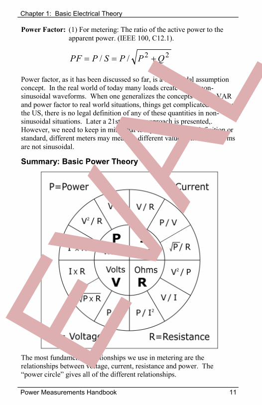
Summary: Basic Power Theory
The most fundamental relationships we use in metering are the relationships between voltage, current, resistance and power. The “power circle” gives all of the different relationships.
Power Factor: (1) For metering: The ratio of the active power to the apparent power. (IEEE 100, C12.1).
Power factor, as it has been discussed so far, is a sinusoidal assumption concept. In the real world of today many loads create highly non-sinusoidal waveforms. When one generalizes the concepts of VA, VAR and power factor to real world situations, things get complicated. Today in the US, there is no legal definition of any of these quantities in non-sinusoidal situations. Later a 21st century approach is presented,. However, we need to keep in mind that today, with no legal definition or standard, different meters may measure different values when waveforms are not sinusoidal.
22// QPPSPPF
Chapter 1: Basic Electrical Theory
12 Power Measurements Handbook
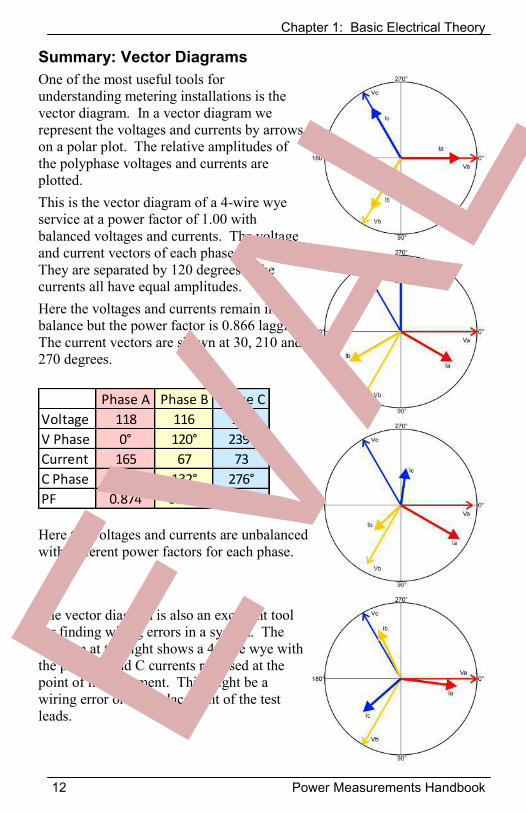
Summary: Vector Diagrams One of the most useful tools for understanding metering installations is the vector diagram. In a vector diagram we represent the voltages and currents by arrows on a polar plot. The relative amplitudes of the polyphase voltages and currents are plotted. This is the vector diagram of a 4-wire wye service at a power factor of 1.00 with balanced voltages and currents. The voltage and current vectors of each phase are aligned. They are separated by 120 degrees. The currents all have equal amplitudes. Here the voltages and currents remain in balance but the power factor is 0.866 lagging. The current vectors are shown at 30, 210 and 270 degrees.
Here the voltages and currents are unbalanced with different power factors for each phase.
The vector diagram is also an excellent tool for finding wiring errors in a system. The diagram at the right shows a 4-wire wye with the phase B and C currents reversed at the point of measurement. This might be a wiring error or a misplacement of the test leads.
Phase A Phase B Phase CVoltage 118 116 120V Phase 0° 120° 239°Current 165 67 73C Phase 29° 132° 276°PF 0.874 0.978 0.798
Chapter 1: Basic Electrical Theory
Power Measurements Handbook 13
Power Measurement in the Digital World The previous equations apply only to systems with sinusoidal waveforms. In the modern world of complex non-linear loads, voltage and current are seldom pure sinusoids, and are often very highly distorted. Because loads can now be electronically switched, they can also vary dramatically over very short periods of time. In the world of mechanical power meters today’s load waveforms presented unsolvable measurement problems.
Today all modern digital meters measure voltage and current waveforms by digitizing them using many samples per cycle. This has changed the approaches that we can use for measuring power quantities. There are two fundamentally different approaches that can be used: 1) computation in the time domain and 2) computation in the frequency (Fourier) domain. Provided that the waveforms are repetitive over the number of cycles in the FFT, both approaches give identical answers for active power (P) and apparent power (S). There is no direct computation for reactive power in the time domain. Measurement of active power in the time domain is very straight forward. We need simply sum up the product of instantaneous voltage and current over the period of time we desire (provided that the time period is an integral number of cycles).
where N is the number of measurements per cycle
Apparent power is also quite easy to measure in the digital world. We can directly calculate the RMS voltage and current.
Reactive power cannot be computed directly from the data in the time domain. For that reason, in the time domain we derive Q from the other two directly measured quantities as:
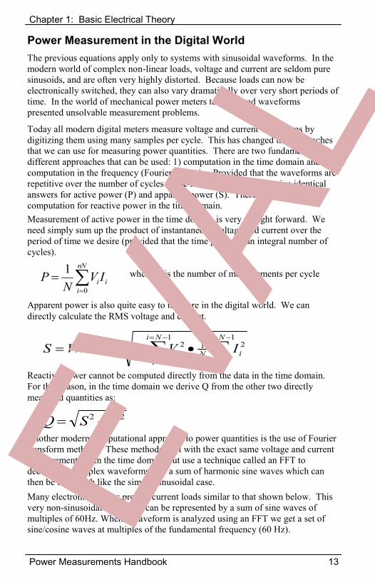
Another modern computational approach to power quantities is the use of Fourier transform methods. These methods start with the exact same voltage and current measurements as in the time domain but use a technique called an FFT to decompose complex waveforms into a sum of harmonic sine waves which can then be dealt with like the simple sinusoidal case. Many electronic devices present current loads similar to that shown below. This very non-sinusoidal waveform can be represented by a sum of sine waves of multiples of 60Hz. When a waveform is analyzed using an FFT we get a set of sine/cosine waves at multiples of the fundamental frequency (60 Hz).
22 PSQ
nN
iii IV
NP
0
1
1
0
211
0
21Ni
iiN
Ni
iiNrmsrms IVIVS
Chapter 1: Basic Electrical Theory
14 Power Measurements Handbook
The historical approach of calculating active power and reactive power was driven by the technology available in the early days of electric power. These approaches ignored harmonics and rapidly changing non-harmonic situations. Today these situations are the norm. Today even though technology is available to accurately compute all power quantities directly from the sampled data, many meters still emulate the old approaches so their answers will be consistent with the old results. With today’s technology the approaches defined above can easily be implemented so as to provide consistent and accurate measurement of all power quantities. Though active power is generally how energy is currently billed, apparent power better measures the real cost of providing the service to the customer. Since computing apparent power is easy to do with modern technology, we should be looking to switching to it as the measure of energy for the future.
nnnnn
nnnn dbcaCosIVP
1)(
1
22
1
22 )()(n
nnn
nn dcbaS
nnnnn
nnnn dbcaSinIVQ
1)(
11
)()()(2)( 000
nnnn tnSinbtnCosatnSinVtV nn
11
)()()(2)( 000
nnnn tnSindtnCosctnSinItI nn
nnn
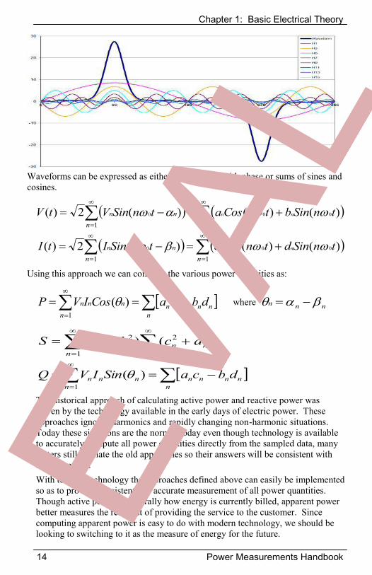
Waveforms can be expressed as either sums of sine with phase or sums of sines and cosines.
Using this approach we can compute the various power quantities as:
where
Chapter 1: Basic Electrical Theory
Power Measurements Handbook 15
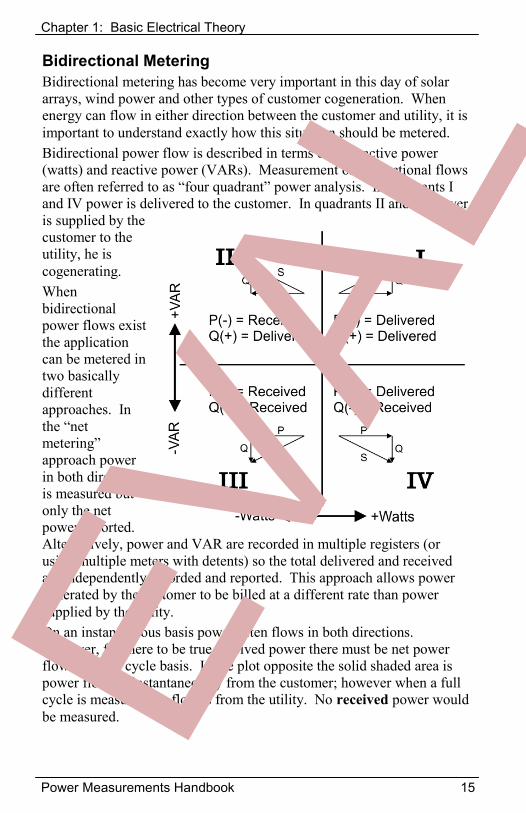
Bidirectional Metering Bidirectional metering has become very important in this day of solar arrays, wind power and other types of customer cogeneration. When energy can flow in either direction between the customer and utility, it is important to understand exactly how this situation should be metered. Bidirectional power flow is described in terms of both active power (watts) and reactive power (VARs). Measurement of bidirectional flows are often referred to as “four quadrant” power analysis. In quadrants I and IV power is delivered to the customer. In quadrants II and III power is supplied by the customer to the utility, he is cogenerating. When bidirectional power flows exist the application can be metered in two basically different approaches. In the “net metering” approach power in both directions is measured but only the net power reported. Alternatively, power and VAR are recorded in multiple registers (or using multiple meters with detents) so the total delivered and received are independently recorded and reported. This approach allows power generated by the customer to be billed at a different rate than power supplied by the utility. On an instantaneous basis power often flows in both directions. However, for there to be true received power there must be net power flow on a full cycle basis. In the plot opposite the solid shaded area is power flowing instantaneously from the customer; however when a full cycle is measured the flow is from the utility. No received power would be measured.
Chapter 1: Basic Electrical Theory
16 Power Measurements Handbook
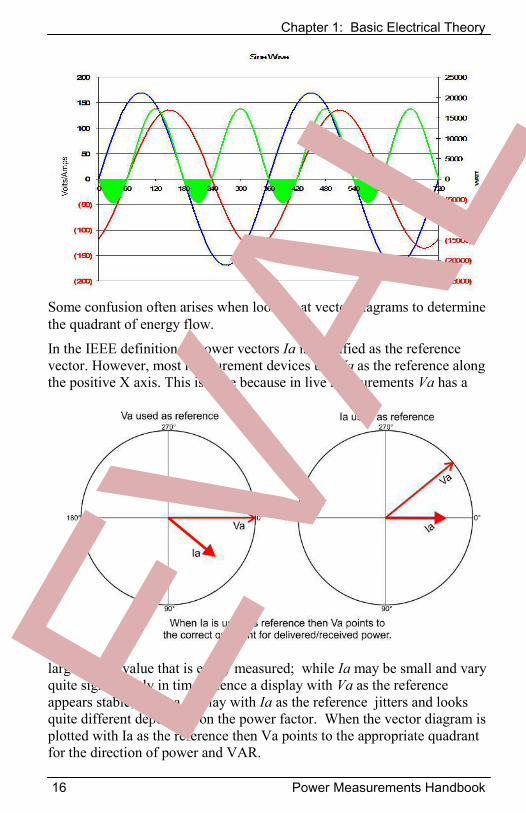
Some confusion often arises when looking at vector diagrams to determine the quadrant of energy flow.
In the IEEE definition of power vectors Ia is specified as the reference vector. However, most measurement devices use Va as the reference along the positive X axis. This is done because in live measurements Va has a
large, stable value that is easily measured; while Ia may be small and vary quite significantly in time. Hence a display with Va as the reference appears stable, while a display with Ia as the reference jitters and looks quite different depending on the power factor. When the vector diagram is plotted with Ia as the reference then Va points to the appropriate quadrant for the direction of power and VAR.
Chapter 2: Introduction to Metering
Power Measurements Handbook 17
Metering Standards Meters are the billing tool for the electric power industry. They measure energy consumption and a number of related quantities which are used to generate the customer’s bill. In the United States the standard for meters is ANSI C12. The C12 standard is published by NEMA. It consists of 17 independent standards published as C12.n. ANSI standards are strictly voluntary. They do not carry the force of law. However, many state public service commissions mandate that they be followed by utilities. C12 recognizes two styles of meters: (1) socket based (designated by an S), (2) bottom fed (designated by an A). There are also three non-C12 meter styles which have limited use: (1) bottom socket (designated by a B) generally obsolete, (2) high current, bus connected (designated by a K) for 400A and 600A services, (3) panel mount (no letter designation). Most meters in service are socket based. ANSI C12.1 is the base standard for all meters both Blondel and non-Blondel. ANSI C12.20 is a supplemental standard for Blondel meters of accuracy classes 0.5 and 0.2. C12.20 is currently under revision to add a 0.1 class. Some meters which have Blondel compliant applications can also be used in non-Blondel compliant ways. Appendix A provides detailed analysis with practical examples of the errors which can be expected in common non-Blondel applications. ANSI C12.10 defines the physical configuration for approved meter forms.
Critical Information from ANSI C12.1 and ANSI C12.20
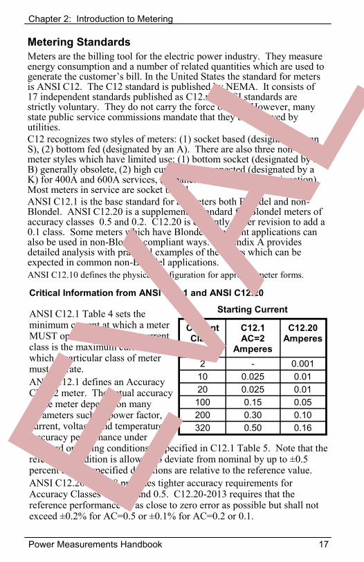
ANSI C12.1 Table 4 sets the minimum current at which a meter MUST operate. Note: The current class is the maximum current at which a particular class of meter must operate. ANSI C12.1 defines an Accuracy Class 2 meter. The actual accuracy of the meter depends on many parameters such as power factor, current, voltage, and temperature. Accuracy performance under standard operating conditions is specified in C12.1 Table 5. Note that the reference condition is allowed to deviate from nominal by up to ±0.5 percent and all specified deviations are relative to the reference value. ANSI C12.20 Table 8 provides tighter accuracy requirements for Accuracy Classes 0.1, 0.2 and 0.5. C12.20-2013 requires that the reference performance be as close to zero error as possible but shall not exceed ±0.2% for AC=0.5 or ±0.1% for AC=0.2 or 0.1.
Starting Current
Current Class
C12.1 AC=2
Amperes
C12.20 Amperes
2 - 0.001 10 0.025 0.01 20 0.025 0.01 100 0.15 0.05 200 0.30 0.10 320 0.50 0.16
Chapter 2: Introduction to Metering
18 Power Measurements Handbook
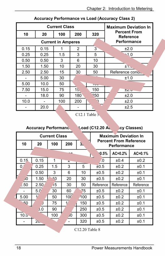
Current Class Maximum Deviation In Percent From
Reference Performance
10 20 100 200 320
Current in Amperes 0.15 0.15 1 2 3 ±2.0 0.25 0.25 1.5 3 5 ±1.0 0.50 0.50 3 6 10 ±1.0 1.50 1.50 10 20 30 ±1.0 2.50 2.50 15 30 50 Reference condition
- 5.00 30 60 75 ±1.0 5.00 10.0 50 100 100 ±1.5 7.50 15.0 75 150 150 ±2.0
- 18.0 90 180 250 ±2.0 10.0 - 100 200 300 ±2.0
- 20.0 - - 320 ±2.5
Accuracy Performance vs Load (Accuracy Class 2)
Current Class Maximum Deviation In Percent From Reference
Performance 10 20 100 200 320
Current in Amperes AC=0.5% AC=0.2% AC=0.1% 0.15 0.15 1 2 3 ±1.0 ±0.4 ±0.2 0.25 0.25 1.5 3 5 ±0.5 ±0.2 ±0.1 0.50 0.50 3 6 10 ±0.5 ±0.2 ±0.1 1.50 1.50 10 20 30 ±0.5 ±0.2 ±0.1 2.50 2.50 15 30 50 Reference Reference Reference
- 5.00 30 60 75 ±0.5 ±0.2 ±0.1 5.00 10.0 50 100 100 ±0.5 ±0.2 ±0.1 7.50 15.0 75 150 150 ±0.5 ±0.2 ±0.1
- 18.0 90 180 250 ±0.5 ±0.2 ±0.1 10.0 - 100 200 300 ±0.5 ±0.2 ±0.1
- 20.0 - - 320 ±0.5 ±0.2 ±0.1
Accuracy Performance vs Load (C12.20 Accuracy Classes)
C12.1 Table 5
C12.20 Table 8
Chapter 2: Introduction to Metering
Power Measurements Handbook 19
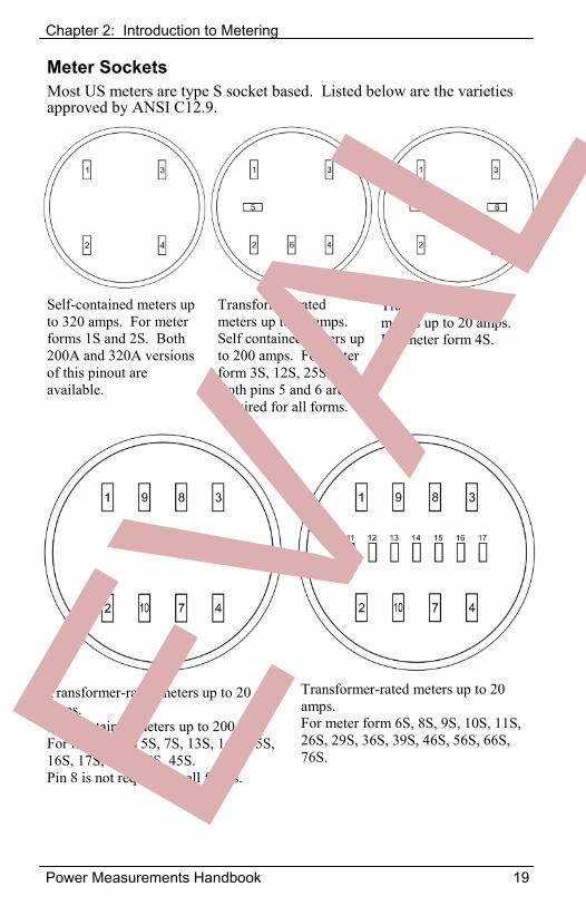
Meter Sockets Most US meters are type S socket based. Listed below are the varieties approved by ANSI C12.9.
Self-contained meters up to 320 amps. For meter forms 1S and 2S. Both 200A and 320A versions of this pinout are available.
Transformer-rated meters up to 20 amps. Self contained meters up to 200 amps. For meter form 3S, 12S, 25S, 32S. Both pins 5 and 6 are not required for all forms.
Transformer-rated meters up to 20 amps. For meter form 4S.
Transformer-rated meters up to 20 amps. Self contained meters up to 200A. For meter form 5S, 7S, 13S, 14S, 15S, 16S, 17S, 24S, 35S, 45S. Pin 8 is not required in all forms.
Transformer-rated meters up to 20 amps. For meter form 6S, 8S, 9S, 10S, 11S, 26S, 29S, 36S, 39S, 46S, 56S, 66S, 76S.
Chapter 2: Introduction to Metering
20 Power Measurements Handbook
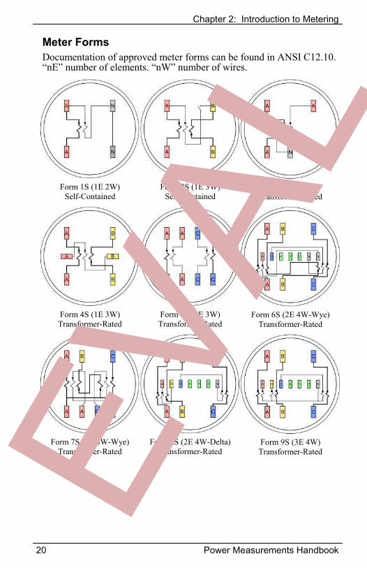
Meter Forms Documentation of approved meter forms can be found in ANSI C12.10. “nE” number of elements. “nW” number of wires.
Form 1S (1E 2W) Self-Contained
Form 2S (1E 3W) Self-Contained
Form 3S (1E 2W) Transformer-Rated
Form 4S (1E 3W) Transformer-Rated
Form 5S (2E 3W) Transformer-Rated
Form 6S (2E 4W-Wye) Transformer-Rated
Form 7S (2E 4W-Wye) Transformer-Rated
Form 8S (2E 4W-Delta) Transformer-Rated
Form 9S (3E 4W) Transformer-Rated
Chapter 2: Introduction to Metering
Power Measurements Handbook 21
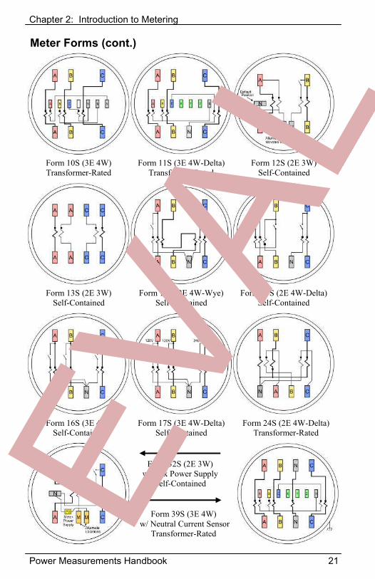
Meter Forms (cont.)
Form 10S (3E 4W) Transformer-Rated
Form 11S (3E 4W-Delta) Transformer-Rated
Form 12S (2E 3W) Self-Contained
Form 13S (2E 3W) Self-Contained
Form 14S (2E 4W-Wye) Self-Contained
Form 15S (2E 4W-Delta) Self-Contained
Form 16S (3E 4W) Self-Contained
Form 17S (3E 4W-Delta) Self-Contained
Form 24S (2E 4W-Delta) Transformer-Rated
Form 32S (2E 3W) w/ Aux Power Supply
Self-Contained
Form 39S (3E 4W) w/ Neutral Current Sensor
Transformer-Rated
Chapter 2: Introduction to Metering
22 Power Measurements Handbook
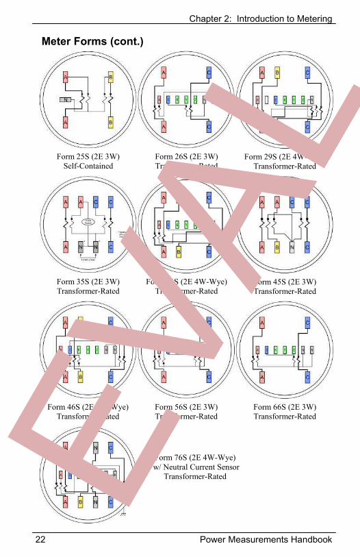
Meter Forms (cont.)
Form 25S (2E 3W) Self-Contained
Form 26S (2E 3W) Transformer-Rated
Form 29S (2E 4W-Wye) Transformer-Rated
Form 35S (2E 3W) Transformer-Rated
Form 36S (2E 4W-Wye) Transformer-Rated
Form 45S (2E 3W) Transformer-Rated
Form 46S (2E 4W-Wye) Transformer-Rated
Form 56S (2E 3W) Transformer-Rated
Form 66S (2E 3W) Transformer-Rated
Form 76S (2E 4W-Wye) w/ Neutral Current Sensor
Transformer-Rated
Chapter 2: Introduction to Metering
Power Measurements Handbook 23
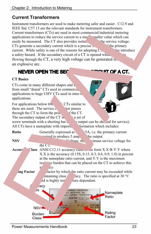
Current Transformers Instrument transformers are used to make metering safer and easier. C12.9 and IEEE Std. C57.13 are the relevant standards for instrument transformers. Current transformers (CTs) are used in most commercial/industrial metering applications to reduce the service current to a much smaller value which can easily be measured. The CT also provides isolation from the service voltage. CTs generate a secondary current which is a precise fraction of the primary current. While safety is one of the reasons for adopting CTs, CTs also introduce a safety hazard. If the secondary circuit of a CT is opened while current is flowing through the CT, a very high voltage can be generated resulting in an explosive arc.
NEVER OPEN THE SECONDARY CIRCUIT OF A CT.CT Basics CTs come in many different shapes and sizes, from small “donut” CTs used in commercial applications to huge UHV CTs used in inter-tie applications. For applications below 600VAC, CTs similar to these are used. The service conductor passes through the CT to form the primary of the CT. The secondary output of the CT is often a set of screw terminals with a shorting bar (so the output can be shorted for service). All CTs have a nameplate with important information which includes: Ratio Generally expressed as XXX:5A, i.e. the primary current
required to produce 5 amps on the output. NSV Nominal Service Voltage, the maximum service voltage for
the CT. Accuracy Class ANSI C12.11 accuracy class in the form X.X B-Y.Y where
X.X is the accuracy (0.15S, 0.15, 0.3, 0.6, 0.9, 1.8) in percent at the nameplate ratio current, and Y.Y is the maximum resistive burden that can be placed on the CT to achieve this accuracy.
Rating Factor The factor by which the ratio current may be exceeded while maintaining class accuracy. The ratio is specified at 30 °C and is highly temperature dependent.
Chapter 2: Introduction to Metering
24 Power Measurements Handbook
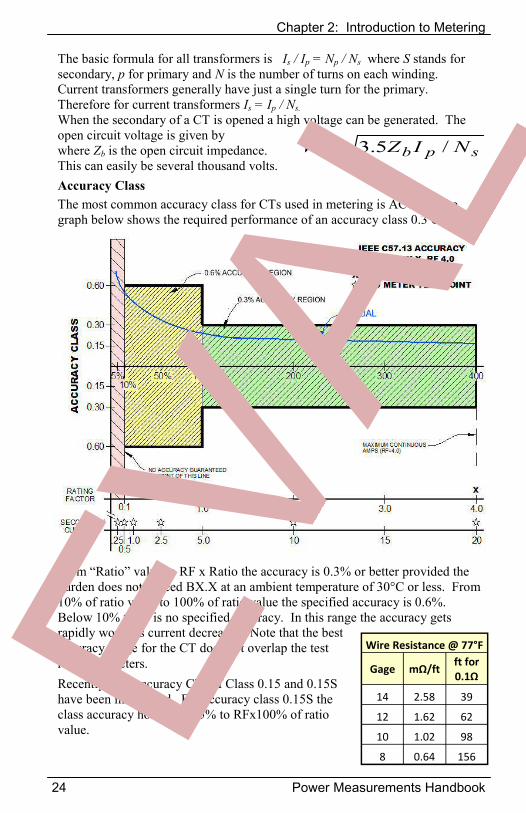
The basic formula for all transformers is Is / Ip = Np / Ns where S stands for secondary, p for primary and N is the number of turns on each winding. Current transformers generally have just a single turn for the primary. Therefore for current transformers Is = Ip / Ns. When the secondary of a CT is opened a high voltage can be generated. The open circuit voltage is given by where Zb is the open circuit impedance. This can easily be several thousand volts. Accuracy Class The most common accuracy class for CTs used in metering is AC 0.3. The graph below shows the required performance of an accuracy class 0.3 CT.
From “Ratio” value to RF x Ratio the accuracy is 0.3% or better provided the burden does not exceed BX.X at an ambient temperature of 30°C or less. From 10% of ratio value to 100% of ratio value the specified accuracy is 0.6%. Below 10% there is no specified accuracy. In this range the accuracy gets rapidly worse as current decreases. Note that the best accuracy range for the CT does not overlap the test range for meters. Recently high accuracy CTs of Class 0.15 and 0.15S have been introduced. For accuracy class 0.15S the class accuracy holds from 5% to RFx100% of ratio value.
spb NIZV /5.3
Wire Resistance @ 77°F
Gage mΩ/ftft for 0.1Ω
14 2.58 39
12 1.62 62
10 1.02 98
8 0.64 156
Chapter 2: Introduction to Metering
Power Measurements Handbook 25
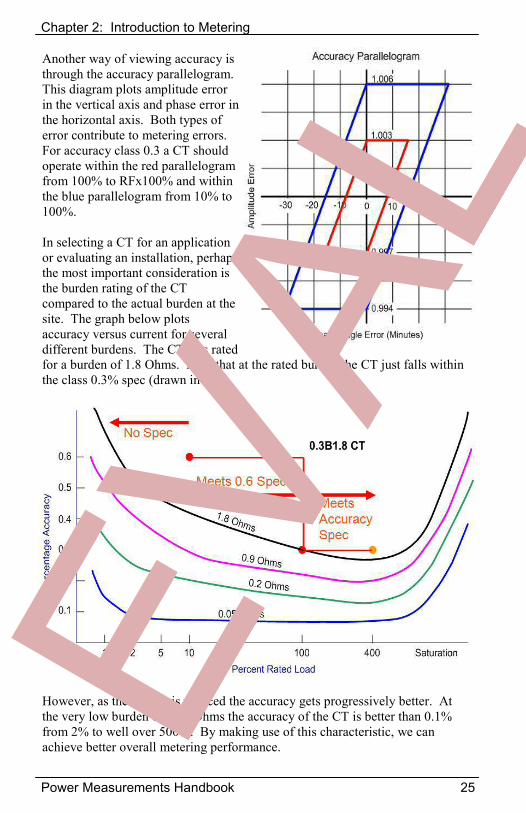
Another way of viewing accuracy is through the accuracy parallelogram. This diagram plots amplitude error in the vertical axis and phase error in the horizontal axis. Both types of error contribute to metering errors. For accuracy class 0.3 a CT should operate within the red parallelogram from 100% to RFx100% and within the blue parallelogram from 10% to 100%.
In selecting a CT for an application or evaluating an installation, perhaps the most important consideration is the burden rating of the CT compared to the actual burden at the site. The graph below plots accuracy versus current for several different burdens. The CT was rated for a burden of 1.8 Ohms. Note that at the rated burden the CT just falls within the class 0.3% spec (drawn in red).
However, as the burden is reduced the accuracy gets progressively better. At the very low burden of 0.05 Ohms the accuracy of the CT is better than 0.1% from 2% to well over 500%. By making use of this characteristic, we can achieve better overall metering performance.
Chapter 2: Introduction to Metering
26 Power Measurements Handbook
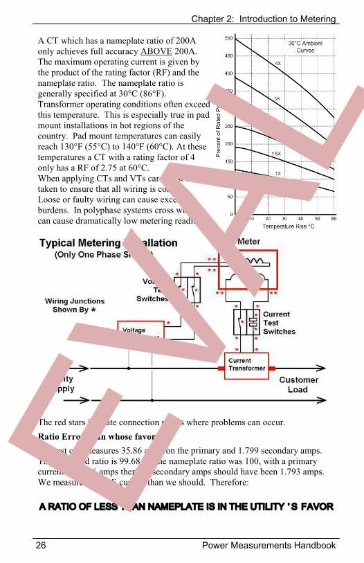
A CT which has a nameplate ratio of 200A only achieves full accuracy ABOVE 200A. The maximum operating current is given by the product of the rating factor (RF) and the nameplate ratio. The nameplate ratio is generally specified at 30°C (86°F). Transformer operating conditions often exceed this temperature. This is especially true in pad mount installations in hot regions of the country. Pad mount temperatures can easily reach 130°F (55°C) to 140°F (60°C). At these temperatures a CT with a rating factor of 4 only has a RF of 2.75 at 60°C. When applying CTs and VTs care must be taken to ensure that all wiring is correct. Loose or faulty wiring can cause excessive burdens. In polyphase systems cross wiring can cause dramatically low metering readings.
The red stars indicate connection points where problems can occur. Ratio Errors—In whose favor? In a test one measures 35.86 amps on the primary and 1.799 secondary amps. The measured ratio is 99.68. If the nameplate ratio was 100, with a primary current of 35.86 amps then the secondary amps should have been 1.793 amps. We measured MORE current than we should. Therefore:
A RATIO OF LESS THAN NAMEPLATE IS IN THE UTILITY ’ S FAVOR
Chapter 3: Distribution Services
Power Measurements Handbook 27
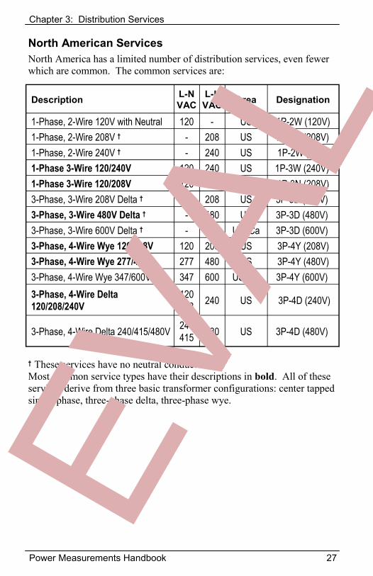
Description L-N VAC
L-L VAC Area Designation
1-Phase, 2-Wire 120V with Neutral 120 - US 1P-2W (120V) 1-Phase, 2-Wire 208V † - 208 US 1P-2W (208V) 1-Phase, 2-Wire 240V † - 240 US 1P-2W (240V) 1-Phase 3-Wire 120/240V 120 240 US 1P-3W (240V) 1-Phase 3-Wire 120/208V 120 208 US 1P-3N (208V) 3-Phase, 3-Wire 208V Delta † - 208 US 3P-3D (208V) 3-Phase, 3-Wire 480V Delta † - 480 US 3P-3D (480V) 3-Phase, 3-Wire 600V Delta † - 600 US, Ca 3P-3D (600V) 3-Phase, 4-Wire Wye 120/208V 120 208 US 3P-4Y (208V) 3-Phase, 4-Wire Wye 277/480V 277 480 US 3P-4Y (480V) 3-Phase, 4-Wire Wye 347/600V 347 600 US, Ca 3P-4Y (600V) 3-Phase, 4-Wire Delta 120/208/240V
120 208 240 US 3P-4D (240V)
3-Phase, 4-Wire Delta 240/415/480V 240 415 480 US 3P-4D (480V)
North American Services North America has a limited number of distribution services, even fewer which are common. The common services are:
† These services have no neutral conductor. Most common service types have their descriptions in bold. All of these services derive from three basic transformer configurations: center tapped single-phase, three-phase delta, three-phase wye.
Chapter 3: Distribution Services
28 Power Measurements Handbook
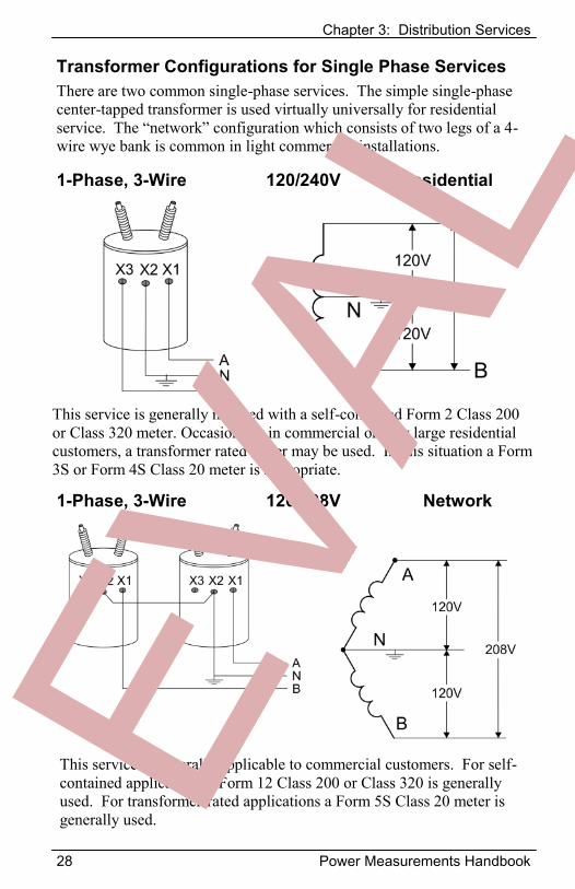
Transformer Configurations for Single Phase Services There are two common single-phase services. The simple single-phase center-tapped transformer is used virtually universally for residential service. The “network” configuration which consists of two legs of a 4-wire wye bank is common in light commercial installations.
1-Phase, 3-Wire 120/240V Residential
1-Phase, 3-Wire 120/208V Network
This service is generally metered with a self-contained Form 2 Class 200 or Class 320 meter. Occasionally in commercial or very large residential customers, a transformer rated meter may be used. In this situation a Form 3S or Form 4S Class 20 meter is appropriate.
This service is generally applicable to commercial customers. For self-contained applications a Form 12 Class 200 or Class 320 is generally used. For transformer-rated applications a Form 5S Class 20 meter is generally used.
Chapter 3: Distribution Services
Power Measurements Handbook 29
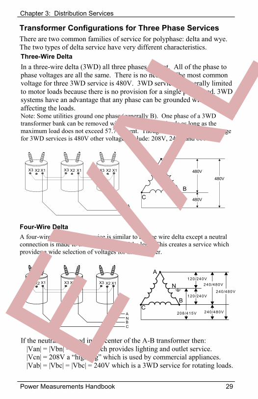
Transformer Configurations for Three Phase Services There are two common families of service for polyphase: delta and wye. The two types of delta service have very different characteristics. Three-Wire Delta In a three-wire delta (3WD) all three phases are hot. All of the phase to phase voltages are all the same. There is no neutral. The most common voltage for three 3WD service is 480V. 3WD service is generally limited to motor loads because there is no provision for a single phase load. 3WD systems have an advantage that any phase can be grounded without affecting the loads. Note: Some utilities ground one phase (generally B). One phase of a 3WD transformer bank can be removed without affecting the loads as long as the maximum load does not exceed 57.7 percent. Though the most common voltage for 3WD services is 480V other voltages include: 208V, 240V and 600V.
Four-Wire Delta A four-wire delta (4WD) service is similar to a three wire delta except a neutral connection is made to the center of one of the legs. This creates a service which provides a wide selection of voltages for the customer.
X1X2X3 X1X2X3 X1X2X3
ANBC
A
CB
N240/480V
120/240V
120/240V
240/480V
208/415V 240/480V
If the neutral is placed in the center of the A-B transformer then: |Van| = |Vbn| = 120V which provides lighting and outlet service. |Vcn| = 208V a “high leg” which is used by commercial appliances.|Vab| = |Vbc| = |Vbc| = 240V which is a 3WD service for rotating loads.
X1X2X3 X1X2X3 X1X2X3
ABC
A
CB
480V
480V
480V
Chapter 3: Distribution Services
30 Power Measurements Handbook
X1X2X3 X1X2X3 X1X2X3
A
N
BC
C
B
N
208/480/600V
208/480/600V
A
208/480/600V
120/277/347V
120/277/347V
120/277/347V
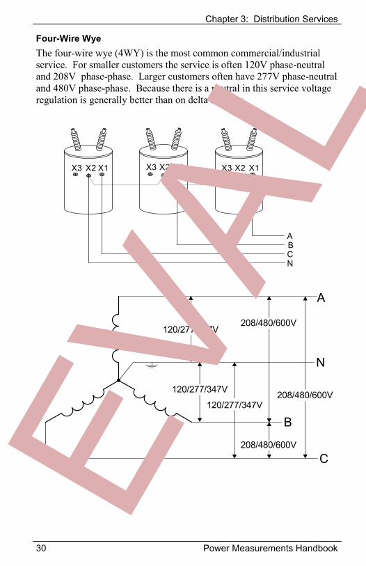
Four-Wire Wye The four-wire wye (4WY) is the most common commercial/industrial service. For smaller customers the service is often 120V phase-neutral and 208V phase-phase. Larger customers often have 277V phase-neutral and 480V phase-phase. Because there is a neutral in this service voltage regulation is generally better than on delta services.
Chapter 4: Service Types - Single Phase
Power Measurements Handbook 31
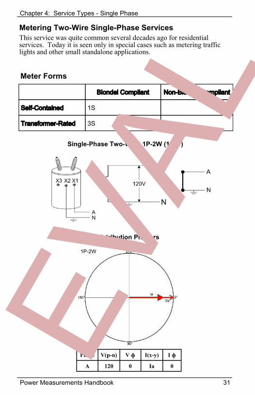
Metering Two-Wire Single-Phase Services This service was quite common several decades ago for residential services. Today it is seen only in special cases such as metering traffic lights and other small standalone applications.
Blondel Compliant Non-Blondel Compliant
Self-Contained 1S
Transformer-Rated 3S
Meter Forms
1P-2W
Single-Phase Two-Wire 1P-2W (120V)
Distribution Phasors
Phase V(p-n) V ɸ I(x-y) I ɸ
A 120 0 Ia 0
Chapter 4: Service Types - Single Phase
32 Power Measurements Handbook
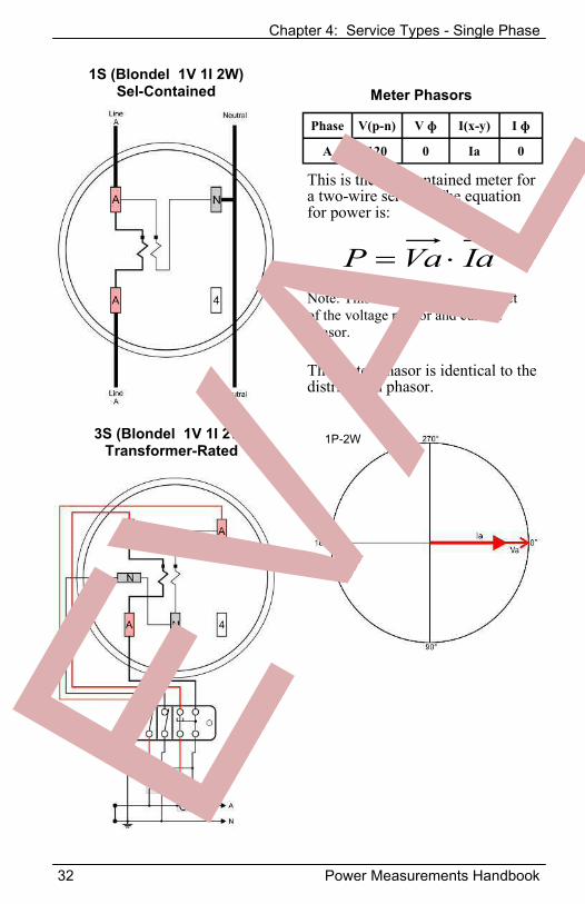
1S (Blondel 1V 1I 2W) Sel-Contained
Phase V(p-n) V ɸ I(x-y) I ɸ
A 120 0 Ia 0
This is the self-contained meter for a two-wire service. The equation for power is:
IaVaP Note: This is the vector dot product of the voltage phasor and current phasor.
Meter Phasors
3S (Blondel 1V 1I 2W) Transformer-Rated
1P-2W
The meter phasor is identical to the distribution phasor.
Chapter 2: Introduction to Metering
Power Measurements Handbook 33
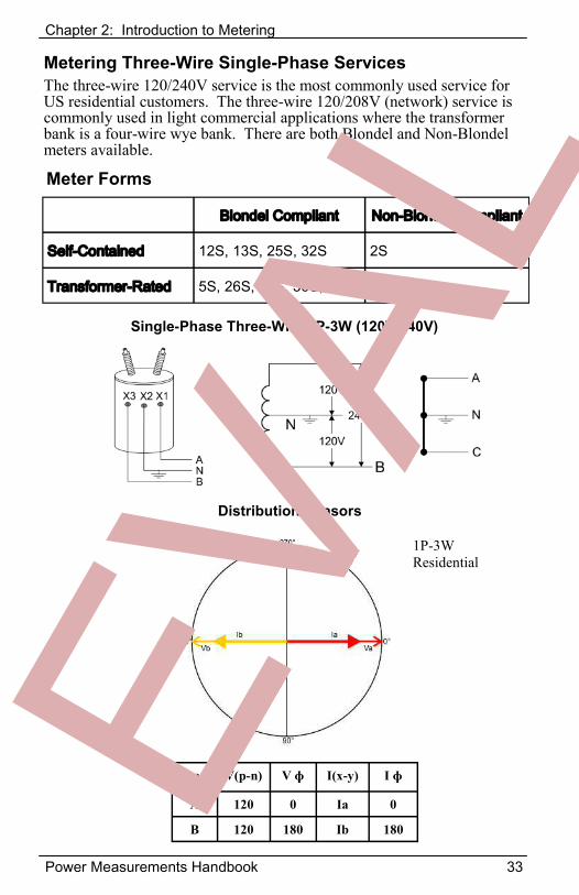
Metering Three-Wire Single-Phase Services The three-wire 120/240V service is the most commonly used service for US residential customers. The three-wire 120/208V (network) service is commonly used in light commercial applications where the transformer bank is a four-wire wye bank. There are both Blondel and Non-Blondel meters available.
Blondel Compliant Non-Blondel Compliant
Self-Contained 12S, 13S, 25S, 32S 2S
Transformer-Rated 5S, 26S, 45S, 56S, 66S 4S
Meter Forms
Single-Phase Three-Wire 1P-3W (120V/240V)
Phase V(p-n) V ɸ I(x-y) I ɸ
A 120 0 Ia 0
B 120 180 Ib 180
1P-3W
Distribution Phasors
1P-3W Residential
Chapter 2: Introduction to Metering
34 Power Measurements Handbook
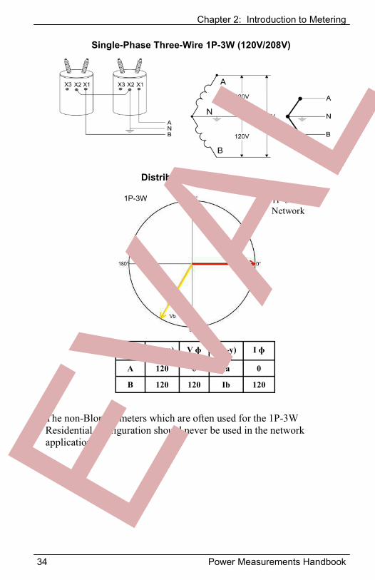
Single-Phase Three-Wire 1P-3W (120V/208V)
Distribution Phasors
Phase V(p-n) V ɸ I(x-y) I ɸ
A 120 0 Ia 0
B 120 120 Ib 120
The non-Blondel meters which are often used for the 1P-3W Residential configuration should never be used in the network application.
1P-3W 1P-3W Network
Chapter 4: Service Types - Single Phase
Power Measurements Handbook 35
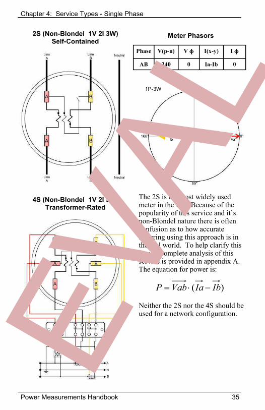
)( IbIaVabP
2S (Non-Blondel 1V 2I 3W) Self-Contained
The 2S is the most widely used meter in the US. Because of the popularity of this service and it’s non-Blondel nature there is often confusion as to how accurate metering using this approach is in the real world. To help clarify this issue a complete analysis of this service is provided in appendix A. The equation for power is:
Phase V(p-n) V ɸ I(x-y) I ɸ
AB 240 0 Ia-Ib 0
1P-3W
Meter Phasors
4S (Non-Blondel 1V 2I 3W) Transformer-Rated
Neither the 2S nor the 4S should be used for a network configuration.
Chapter 4: Service Types - Single Phase
36 Power Measurements Handbook
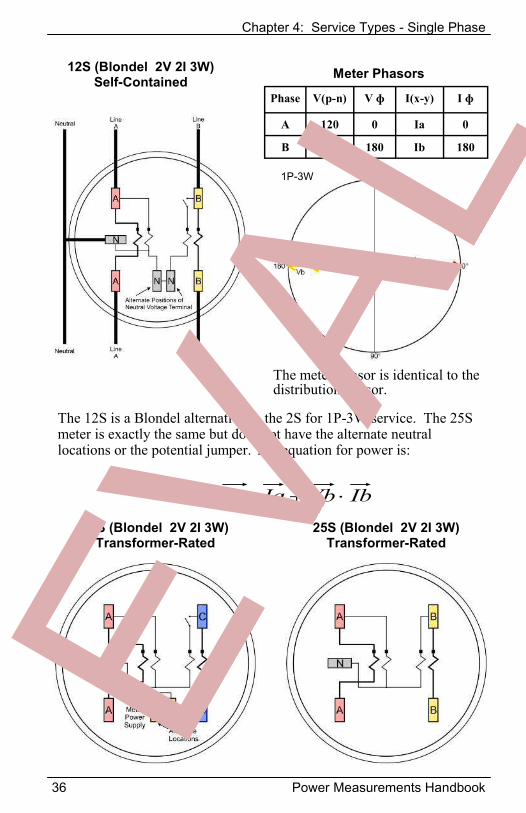
12S (Blondel 2V 2I 3W) Self-Contained
The 12S is a Blondel alternative to the 2S for 1P-3W service. The 25S meter is exactly the same but does not have the alternate neutral locations or the potential jumper. The equation for power is:
IbVbIaVaP
1P-3W
Meter Phasors
Phase V(p-n) V ɸ I(x-y) I ɸ
A 120 0 Ia 0
B 120 180 Ib 180
The meter phasor is identical to the distribution phasor.
32S (Blondel 2V 2I 3W) Transformer-Rated
25S (Blondel 2V 2I 3W) Transformer-Rated
Chapter 4: Service Types - Single Phase
Power Measurements Handbook 37
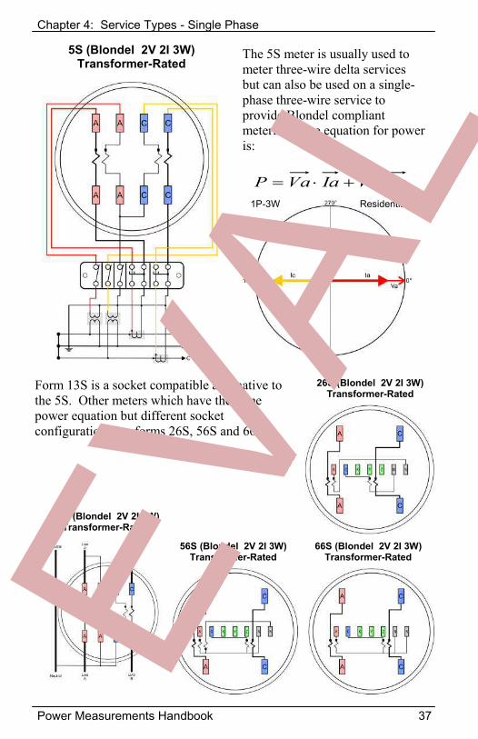
5S (Blondel 2V 2I 3W) Transformer-Rated
The 5S meter is usually used to meter three-wire delta services but can also be used on a single-phase three-wire service to provide Blondel compliant metering. The equation for power is:
IcVcIaVaP
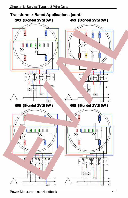
Form 13S is a socket compatible alternative to the 5S. Other meters which have the same power equation but different socket configurations are forms 26S, 56S and 66S.
1P-3W Residential
13S (Blondel 2V 2I 3W) Transformer-Rated
26S (Blondel 2V 2I 3W) Transformer-Rated
56S (Blondel 2V 2I 3W) Transformer-Rated
66S (Blondel 2V 2I 3W) Transformer-Rated
Chapter 4: Service Types - Single Phase
38 Power Measurements Handbook
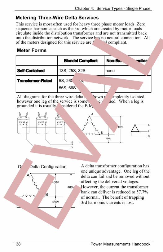
Metering Three-Wire Delta Services This service is most often used for heavy three phase motor loads. Zero sequence harmonics such as the 3rd which are created by motor loads circulate inside the distribution transformer and are not transmitted back onto the distribution network. The service has no neutral connection. All of the meters designed for this service are Blondel compliant.
Blondel Compliant Non-Blondel Compliant
Self-Contained 13S, 25S, 32S none
Transformer-Rated 5S, 26S, 35S, 45S, 56S, 66S
none
Meter Forms
All diagrams for the three-wire delta are shown as completely isolated, however one leg of the service is sometimes grounded. When a leg is grounded it is usually considered the B leg.
A delta transformer configuration has one unique advantage. One leg of the delta can fail and be removed without affecting the delivered voltages. However, the current the transformer bank can deliver is reduced to 57.7% of normal. The benefit of trapping 3rd harmonic currents is lost.
Chapter 4: Service Types - 3-Wire Delta
Power Measurements Handbook 39
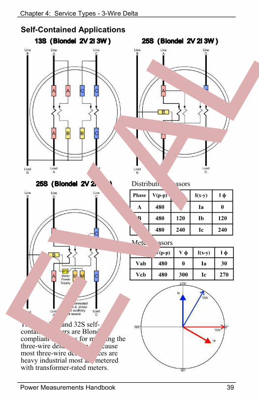
Self-Contained Applications 13S ( Blondel 2V 2I 3W ) 25S ( Blondel 2V 2I 3W )
25S ( Blondel 2V 2I 3W )Phase V(p-p) V ɸ I(x-y) I ɸ
A 480 0 Ia 0
B 480 120 Ib 120
C 480 240 Ic 240
Distribution phasors
Meter phasors Phase V(p-p) V ɸ I(x-y) I ɸ
Vab 480 0 Ia 30
Vcb 480 300 Ic 270
The 13S, 25S and 32S self-contained meters are Blondel compliant solutions for metering the three-wire delta service. Because most three-wire delta services are heavy industrial most are metered with transformer-rated meters.
Chapter 4: Service Types - 3-Wire Delta
40 Power Measurements Handbook
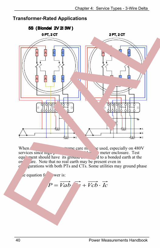
5S ( Blondel 2V 2I 3W )
Transformer-Rated Applications
0 PT, 2 CT 2 PT, 2 CT
When there are no PTs extreme care must be used, especially on 480V services since high potentials exist within the meter enclosure. Test equipment should have its ground connected to a bonded earth at the enclosure. Note that no real earth may be present even in configurations with both PTs and CTs. Some utilities may ground phase B. The equation for power is:
IcVcbIaVabP
Chapter 4: Service Types - 3-Wire Delta
Power Measurements Handbook 41
26S ( Blondel 2V 2I 3W )Transformer-Rated Applications (cont.)
45S ( Blondel 2V 2I 3W )
56S ( Blondel 2V 2I 3W ) 66S ( Blondel 2V 2I 3W )
Chapter 4: Service Types - 4-Wire Delta
42 Power Measurements Handbook
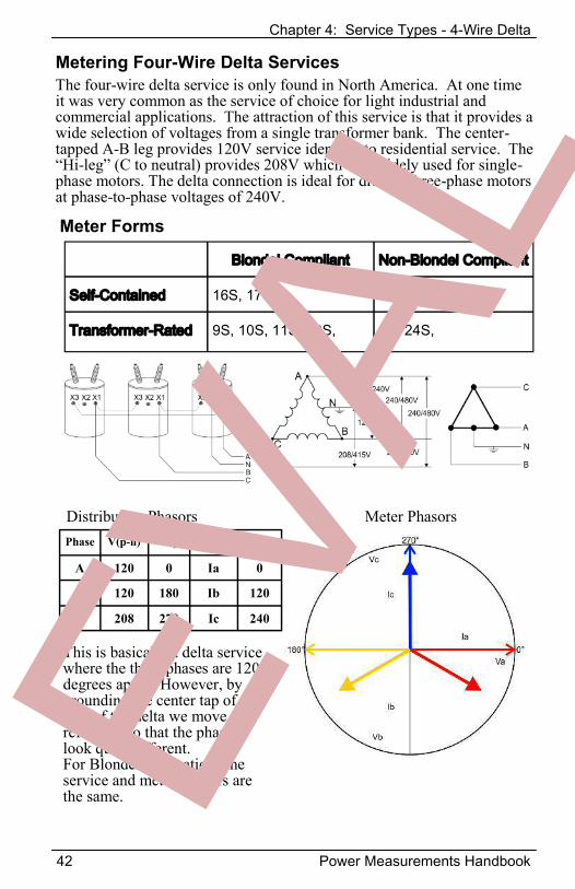
Metering Four-Wire Delta Services The four-wire delta service is only found in North America. At one time it was very common as the service of choice for light industrial and commercial applications. The attraction of this service is that it provides a wide selection of voltages from a single transformer bank. The center-tapped A-B leg provides 120V service identical to residential service. The “Hi-leg” (C to neutral) provides 208V which was widely used for single-phase motors. The delta connection is ideal for driving three-phase motors at phase-to-phase voltages of 240V.
Blondel Compliant Non-Blondel Compliant
Self-Contained 16S, 17S 15S
Transformer-Rated 9S, 10S, 11S, 39S, 8S, 24S,
Meter Forms
Phase V(p-n) V ɸ I(x-y) I ɸ
A 120 0 Ia 0
B 120 180 Ib 120
C 208 270 Ic 240
Distribution Phasors Meter Phasors
This is basically a delta service where the three phases are 120 degrees apart. However, by grounding the center tap of one side of the delta we move the reference so that the phasors look quite different. For Blondel applications the service and meter phasors are the same.
Chapter 4: Service Types - 4-Wire Delta
Power Measurements Handbook 43
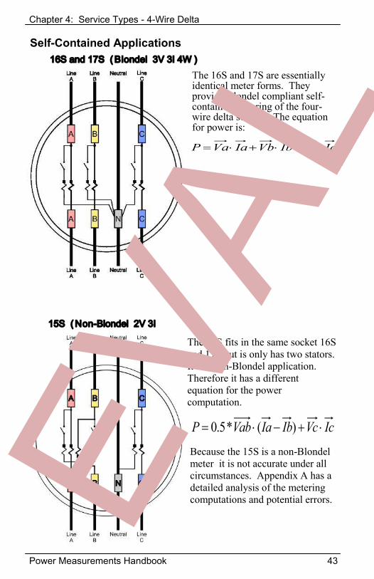
Self-Contained Applications 16S and 17S ( Blondel 3V 3I 4W )
15S ( Non-Blondel 2V 3I
The 16S and 17S are essentially identical meter forms. They provide Blondel compliant self-contained metering of the four-wire delta service. The equation for power is:
IcVcIbVbIaVaP
IcVcIbIaVabP )(*5.0
The 15S fits in the same socket 16S and 17S but is only has two stators. It is a non-Blondel application. Therefore it has a different equation for the power computation.
Because the 15S is a non-Blondel meter it is not accurate under all circumstances. Appendix A has a detailed analysis of the metering computations and potential errors.
Chapter 4: Service Types - 4-Wire Delta
44 Power Measurements Handbook
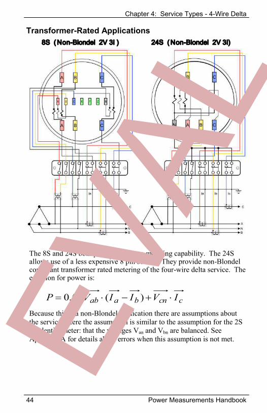
8S ( Non-Blondel 2V 3I )Transformer-Rated Applications
24S ( Non-Blondel 2V 3I)
The 8S and 24S both provide the same metering capability. The 24S allows use of a less expensive 8 pin socket. They provide non-Blondel compliant transformer rated metering of the four-wire delta service. The equation for power is:
ccnbaab IVIIVP )(*5.0Because this is a non-Blondel application there are assumptions about the service. Here the assumption is similar to the assumption for the 2S residential meter: that the voltages Van and Vbn are balanced. See Appendix A for details about errors when this assumption is not met.
Chapter 4: Service Types - 4-Wire Delta
Power Measurements Handbook 45
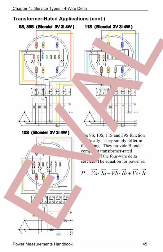
9S, 39S ( Blondel 3V 3I 4W )
Transformer-Rated Applications (cont.)
10S ( Blondel 3V 3I 4W )
11S ( Blondel 3V 3I 4W )
The 9S, 10S, 11S and 39S function identically. They simply differ in the wiring. They provide Blondel compliant transformer-rated metering of the four-wire delta service. The equation for power is:
IcVcIbVbIaVaP
Chapter 4: Service Types - 4-Wire Wye
46 Power Measurements Handbook
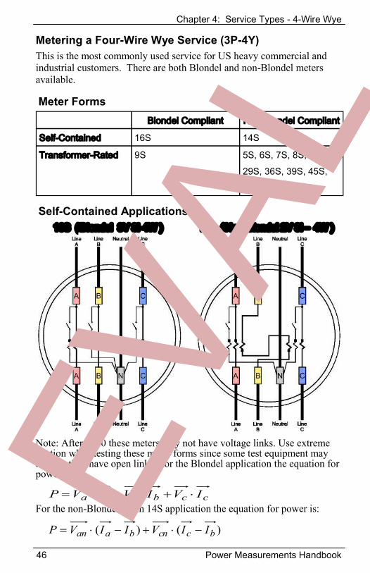
Metering a Four-Wire Wye Service (3P-4Y) This is the most commonly used service for US heavy commercial and industrial customers. There are both Blondel and non-Blondel meters available.
Blondel Compliant Non-Blondel Compliant
Self-Contained 16S 14S
Transformer-Rated 9S 5S, 6S, 7S, 8S, 10S, 29S, 36S, 39S, 45S, 46S, 76S
Meter Forms
Self-Contained Applications 16S ( Blondel 3V 3I-4W ) 14S ( Non-Blondel 2V 3I – 4W )
Note: After 2010 these meters may not have voltage links. Use extreme caution when testing these meter forms since some test equipment may assume they have open links. For the Blondel application the equation for power is:
For the non-Blondel Form 14S application the equation for power is: ccbbaa IVIVIVP
)()( bccnbaan IIVIIVP
Chapter 4: Service Types - 4-Wire Wye
Power Measurements Handbook 47
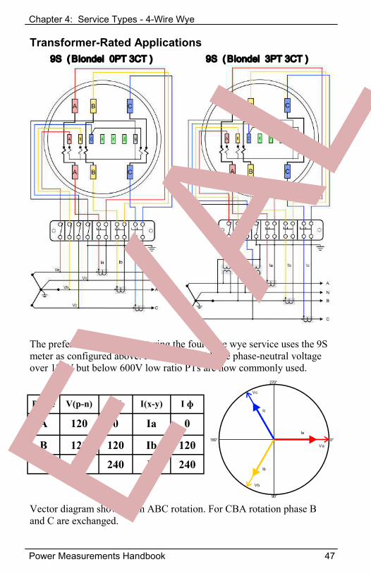
Transformer-Rated Applications 9S ( Blondel 0PT 3CT ) 9S ( Blondel 3PT 3CT )
The preferred method of metering the four-wire wye service uses the 9S meter as configured above. For services with the phase-neutral voltage over 120V but below 600V low ratio PTs are now commonly used.
Phase V(p-n) V ɸ I(x-y) I ɸ
A 120 0 Ia 0
B 120 120 Ib 120
C 120 240 Ic 240
Vector diagram shown with ABC rotation. For CBA rotation phase B and C are exchanged.
0°
90°
180°
270°
Va
Ia
Ic
Vc
Ib
Vb
Chapter 4: Service Types - 4-Wire Wye
48 Power Measurements Handbook
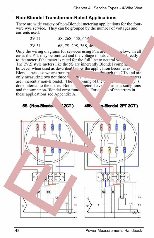
Non-Blondel Transformer-Rated Applications There are wide variety of non-Blondel metering applications for the four-wire wye service. They can be grouped by the number of voltages and currents used. 2V 2I 5S, 26S, 45S, 66S
2V 3I 6S, 7S, 29S, 36S, 46S Only the wiring diagrams for services using PTs are shown below. In all cases the PTs may be omitted and the voltage inputs connected directly to the meter if the meter is rated for the full line to neutral voltage. The 2V2I style meters like the 5S are inherently Blondel compliant, however when used as described below the application becomes non-Blondel because we are running multiple phases through the CTs and are only measuring two not three voltages. For 2V3I style meters the meters are inherently non-Blondel. The combining of the currents vectorally is done internal to the meter. Both style meters have the same assumptions and the same non-Blondel error functions. For details of the errors in these applications see Appendix A.
5S ( Non-Blondel 2PT 2CT ) 45S ( Non-Blondel 2PT 2CT )
Chapter 4: Service Types - 4-Wire Wye
Power Measurements Handbook 49
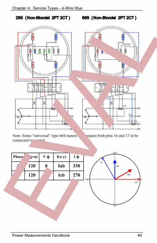
26S ( Non-Blondel 2PT 2CT )
Note: Some “universal” type 66S meters may require both pins 16 and 17 to be connected to neutral.
66S ( Non-Blondel 2PT 2CT )
0°
90°
180°
270°
Icb
Iab
Va
Vc
Phase V(p-n) V ɸ I(x-y) I ɸ
A 120 0 Iab 330
C 120 240 Icb 270
Chapter 4: Service Types - 4-Wire Wye
50 Power Measurements Handbook
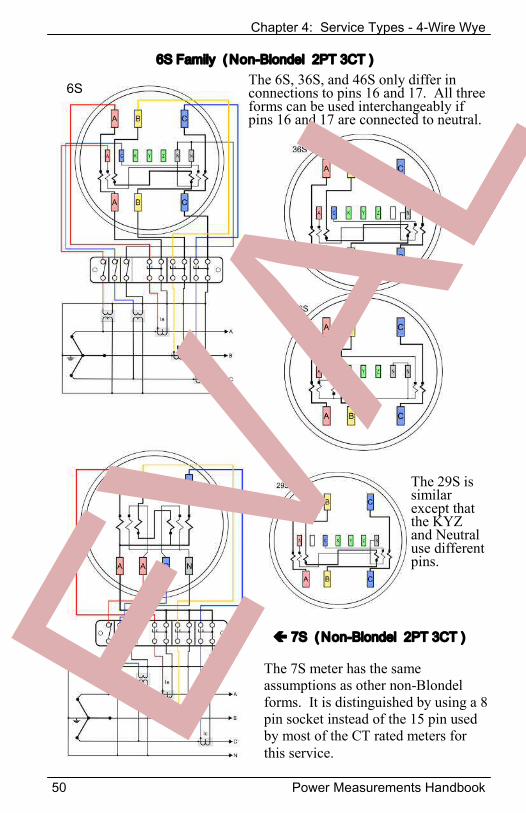
6S Family ( Non-Blondel 2PT 3CT )
7S ( Non-Blondel 2PT 3CT )
The 6S, 36S, and 46S only differ in connections to pins 16 and 17. All three forms can be used interchangeably if pins 16 and 17 are connected to neutral.
The 7S meter has the same assumptions as other non-Blondel forms. It is distinguished by using a 8 pin socket instead of the 15 pin used by most of the CT rated meters for this service.
The 29S is similar except that the KYZ and Neutral use different pins.
6S
Chapter 5: Testing Metering Installations
Power Measurements Handbook 51
Why Test in the Field? There are many reasons why field verification of metering sites is a sound business practice.
The metering site is the utility’s cash register. The utility wants to receive full payment for the services it provides.
The customer wants to be billed fairly. Translate this to mean the lowest bill possible.
The Public Service Commission requires that billing be “fair”. To insure this, a field verification program may be mandated.
The utility needs to assure itself that the site is wired to code and meets safety standards.
The first three of the reasons are all economic. They boil down to the simple statement: Everyone wants a fair and accurate bill. Most customers believe that their bill is too high. The reality is:
Almost anything that can go wrong with a metering installation reduces a customer’s bill rather than
increasing it. The discussion on field testing here will concentrate on transformer-rated installations exclusively. In direct connected installations there is essentially nothing to fail except the meter. Formerly with less accurate mechanical meters, a meter might run a little slow with time but in general if it was functioning it was probably OK. Electromechanical meters have life spans in excess of 30 years. We do not have sufficient experience with modern electronic meters to know what the life expectancy will be. However, it is unlikely to be 30 plus years. Failure modes for these meters are still being established. Modern transformer-rated meters are essentially all digital, electronic meters. The meter together with the site wiring, current transformers and potential transformers create a complex measurement system with many failure modes. As customers demand more and more accurate bills, this complexity creates many opportunities for billing errors. Things to Test in the Field
Site wiring - wiring errors can reduce billing by 70% or more CT performance - many things can reduce a CT’s accuracy PT performance - over burdened PTs reduce billing Meter Performance - meters can fail, however the more common
issue is that the conditions in the field are outside of those to which the meter’s performance was verified at type testing.
Chapter 5: Testing Metering Installations
52 Power Measurements Handbook
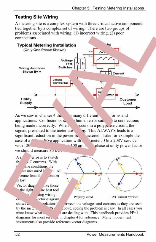
Testing Site Wiring A metering site is a complex system with three critical active components tied together by a complex set of wiring. There are two groups of problems associated with wiring: (1) incorrect wiring, (2) poor connections.
As we saw in chapter 4 there are many different meter forms and applications. Confusion or simple human error can lead to connections being made incorrectly. When this occurs in a polyphase circuit, the signals presented to the meter are wrong. This ALWAYS leads to a significant reduction in the power being metered. Take for example the case of a 4-wire Wye application with a 9S meter. On a 208V service with 120V phase to neutral and 100 amps per phase at unity power factor we should measure 36 kW. A simple error is to switch the B & C currents. With the same conditions the power measured is zero. All revenue from this customer is lost. Vector diagrams like those at the right are the best tool for understanding wiring errors. The vector diagram shows the phase relationship between the voltages and currents as they are seen by the meter. In the 9S case above, seeing the problem is easy. In all cases you must know what service you are dealing with. This handbook provides PF=1 diagrams for most services in chapter 4 for reference. Many modern test instruments also provide reference vector diagrams.
Properly wired B&C current reversed
Chapter 5: Testing Metering Installations
Power Measurements Handbook 53
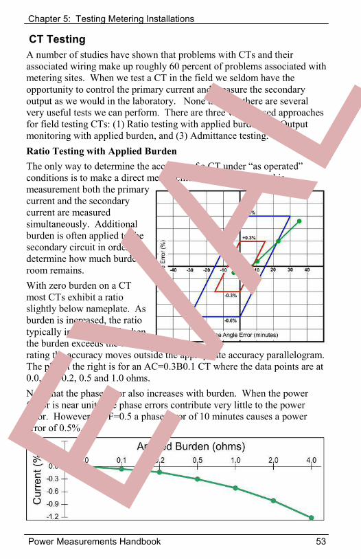
CT Testing A number of studies have shown that problems with CTs and their associated wiring make up roughly 60 percent of problems associated with metering sites. When we test a CT in the field we seldom have the opportunity to control the primary current and measure the secondary output as we would in the laboratory. None the less, there are several very useful tests we can perform. There are three widely used approaches for field testing CTs: (1) Ratio testing with applied burden, (2) Output monitoring with applied burden, and (3) Admittance testing. Ratio Testing with Applied Burden The only way to determine the accuracy of a CT under “as operated” conditions is to make a direct measurement in the field. For this measurement both the primary current and the secondary current are measured simultaneously. Additional burden is often applied to the secondary circuit in order to determine how much burden room remains. With zero burden on a CT most CTs exhibit a ratio slightly below nameplate. As burden is increased, the ratio typically increases until when the burden exceeds the burden rating the accuracy moves outside the appropriate accuracy parallelogram. The plot at the right is for an AC=0.3B0.1 CT where the data points are at 0.0, 0.1, 0.2, 0.5 and 1.0 ohms. Note that the phase error also increases with burden. When the power factor is near unity the phase errors contribute very little to the power error. However at PF=0.5 a phase error of 10 minutes causes a power error of 0.5%.
Chapter 5: Testing Metering Installations
54 Power Measurements Handbook
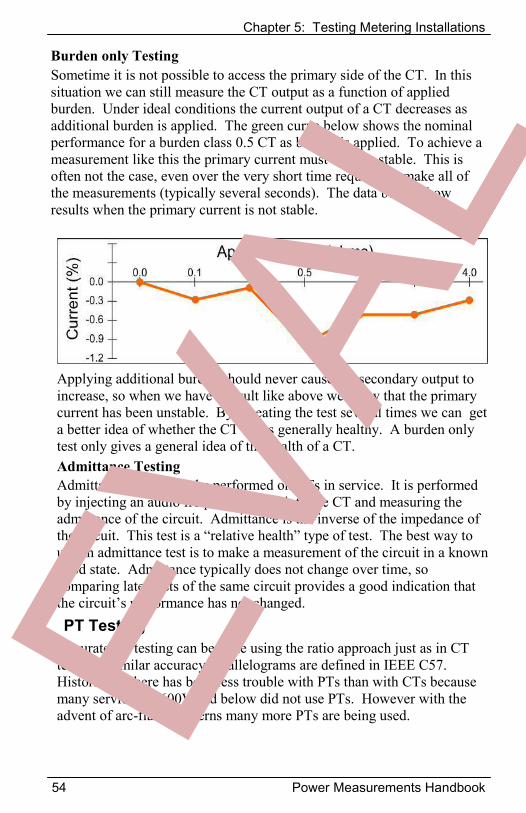
Burden only Testing Sometime it is not possible to access the primary side of the CT. In this situation we can still measure the CT output as a function of applied burden. Under ideal conditions the current output of a CT decreases as additional burden is applied. The green curve below shows the nominal performance for a burden class 0.5 CT as burden is applied. To achieve a measurement like this the primary current must be very stable. This is often not the case, even over the very short time required to make all of the measurements (typically several seconds). The data below show results when the primary current is not stable.
Applying additional burden should never cause the secondary output to increase, so when we have a result like above we know that the primary current has been unstable. By repeating the test several times we can get a better idea of whether the CT looks generally healthy. A burden only test only gives a general idea of the health of a CT. Admittance Testing Admittance testing can be performed on CTs in service. It is performed by injecting an audio frequency signal into the CT and measuring the admittance of the circuit. Admittance is the inverse of the impedance of the circuit. This test is a “relative health” type of test. The best way to use an admittance test is to make a measurement of the circuit in a known good state. Admittance typically does not change over time, so comparing later tests of the same circuit provides a good indication that the circuit’s performance has not changed.PT Testing
Accurate PT testing can be done using the ratio approach just as in CT testing. Similar accuracy parallelograms are defined in IEEE C57. Historically there has been less trouble with PTs than with CTs because many services of 600V and below did not use PTs. However with the advent of arc-flash concerns many more PTs are being used.
Chapter 5: Testing Metering Installations
Power Measurements Handbook 55
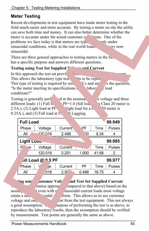
Meter Testing Recent developments in test equipment have made meter testing in the field much easier and more accurate. By testing a meter on site the utility can save both time and money. It can also better determine whether the meter is accurate under the actual customer conditions. One of the problems we face today is that meters are type tested only under sinusoidal conditions, while in the real world loads can be very non-sinusoidal. There are three general approaches to testing meters in the field. Each has a specific purpose and answers different questions. Testing using Test Set Supplied Voltage and Current In this approach the test set provides both the test voltage and current. This allows the laboratory type test results to be reproduced in the field. This type of testing is required by some PSCs and answers the question, “Is the meter meeting its specifications under laboratory load conditions?”Testing is generally performed at the nominal service voltage and three different loads: (1) Full load at PF=1.0 (full load for a Class 20 meter is 2.5A.), (2) Light load at PF=1.0 (light load for a Class 20 meter is 0.25A.), and (3) Full load at PF=0.5 Lagging.
Testing using Customer Voltage and Test Set Supplied Current This is a compromise approach (compared to that above) based on the assumption that even with non-sinusoidal current loads most voltage retain a nearly sinusoidal waveform. This allows us to use customer voltage and only supply current from the test equipment. This not always a good assumption. If the purpose of performing the test is as above, to reproduce the laboratory results, then the assumption should be verified by measurement. Test points are generally the same as above.
Chapter 5: Testing Metering Installations
56 Power Measurements Handbook
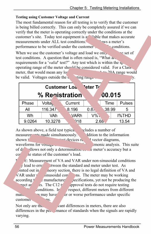
Testing using Customer Voltage and Current The most fundamental reason for all testing is to verify that the customer is being billed correctly. This can only be completely assured if we can verify that the meter is operating correctly under the conditions at the customer’s site. Today test equipment is available that makes accurate measurements under ALL test conditions. This allows a meter’s performance to be verified under the customer’s specific conditions. When we use the customer’s voltage and load we only have one set of test conditions. A question that is often raised is, “What are the requirements for a ‘valid’ test?” Any test which is within the specified operating range of the meter should be considered valid. For a Class 20 meter, that would mean any load within the 100mA to 20A range would be valid. Voltages outside the operating range occur very infrequently.
As shown above, a field test typically includes a number of measurements made simultaneously. In addition to the information shown in the report many test devices record vector diagrams, waveforms for voltage and current and full harmonic analysis. This suite of data allows not only a determination of the meter’s accuracy but a complete status of the customer’s load.NOTE: Measurement of VA and VAR under non-sinusoidal conditions may lead to errors between the standard and meter under test. As pointed out in the theory section, there is no legal definition of VA and VAR under non-sinusoidal conditions. The meter may be working according to the manufacturer’s specifications, yet not be producing the correct answers. The C12 type approval tests do not require testing under these conditions. In this respect, different meters from different manufacturers may have better or worse performance under specific customer conditions. Not only are there significant differences in meters, there are also differences in the performance of standards when the signals are rapidly varying.
Appendix A: Non-Blondel Error Analysis
Power Measurements Handbook 57
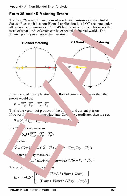
Form 2S and 4S Metering Errors The form 2S is used to meter most residential customers in the United States. Because it is a non-Blondel application it is NOT accurate under all possible circumstances. Form 4S has the same errors. This raises the issue of what kinds of errors can be expected in the real world. The following analysis answers that question.
Blondel Metering 2S Non-Blondel Metering
If we metered the application in a Blondel compliant manner then the power would be:
This is the vector dot product of the voltage and current phasors. If we resolve the vector product into Cartesian coordinates then we get.
In a 2S meter we measure
If we define
The meter actually measures
The error in the measurement is
bbaa IVIVP
bybybxbxayayaxax IVIVIVIVP ****
),()(),( VbyVayVbxVaxVbVaVcyVcxVc
)****(*5.0 IbyVcyIbxVcxIayVcyIaxVcxP
)(*5.0 baab IIVP
)(*)(
)(*)(*5.0
IanyIbnyVbnyVany
IanxIbnxVbnxVanxErr
Appendix A: Non-Blondel Error Analysis
58 Power Measurements Handbook
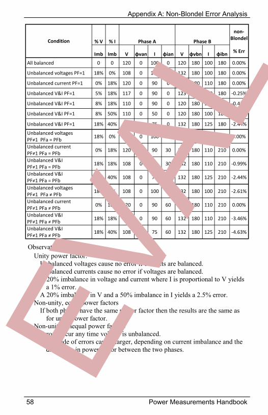
Condition % V % I Phase A Phase B
non-Blondel
Imb Imb V φvan I φian V φvbn I φibn % Err
All balanced 0 0 120 0 100 0 120 180 100 180 0.00%
Unbalanced voltages PF=1 18% 0% 108 0 100 0 132 180 100 180 0.00%
Unbalanced current PF=1 0% 18% 120 0 90 0 120 180 110 180 0.00%
Unbalanced V&I PF=1 5% 18% 117 0 90 0 123 180 110 180 -0.25%
Unbalanced V&I PF=1 8% 18% 110 0 90 0 120 180 110 180 -0.43%
Unbalanced V&I PF=1 8% 50% 110 0 50 0 120 180 100 180 -1.43%
Unbalanced V&I PF=1 18% 40% 108 0 75 0 132 180 125 180 -2.44%
Unbalanced voltages PF≠1 PFa = PFb
18% 0% 108 0 100 30 132 180 100 210 0.00%
Unbalanced current PF≠1 PFa = PFb
0% 18% 120 0 90 30 120 180 110 210 0.00%
Unbalanced V&I PF≠1 PFa = PFb
18% 18% 108 0 90 30 132 180 110 210 -0.99%
Unbalanced V&I PF≠1 PFa = PFb
18% 40% 108 0 75 30 132 180 125 210 -2.44%
Unbalanced voltages PF≠1 PFa ≠ PFb
18% 0% 108 0 100 60 132 180 100 210 -2.61%
Unbalanced current PF≠1 PFa ≠ PFb
0% 18% 120 0 90 60 120 180 110 210 0.00%
Unbalanced V&I PF≠1 PFa ≠ PFb
18% 18% 108 0 90 60 132 180 110 210 -3.46%
Unbalanced V&I PF≠1 PFa ≠ PFb
18% 40% 108 0 75 60 132 180 125 210 -4.63%
Observations: Unity power factor:
Unbalanced voltages cause no error if currents are balanced. Unbalanced currents cause no error if voltages are balanced. A 20% imbalance in voltage and current where I is proportional to V yields
a 1% error. A 20% imbalance in V and a 50% imbalance in I yields a 2.5% error.
Non-unity, equal power factors If both phases have the same power factor then the results are the same as
for unity power factor. Non-unity, unequal power factors
Errors occur any time voltage is unbalanced. Magnitude of errors can be larger, depending on current imbalance and the
difference in power factor between the two phases.
Appendix A: Non-Blondel Error Analysis
Power Measurements Handbook 59
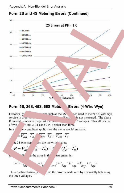
Form 2S and 4S Metering Errors (Continued)
)(*)(*bny
Vbny
Vany
Vbny
Icnx
Vbnx
Vanx
Vbnx
IErr
Form 5S, 26S, 45S, 66S Metering Errors (4-Wire Wye)
Historically a two stator meter such as the 5S has been used to meter a 4-wire wye service in order to save money. The phase B voltage is not measured. The phase B current is measured against the phase A and phase C voltages. This allows use of two stators and 2 CTs and 2 PTs rather than three. In a Blondel compliant application the meter would measure:
In the 5S type application the meter measures:
In this application the error in the measurement is:
This equation basically states that the error is made zero by vectorially balancing the three voltages.
ccnbbnaan IVIVIVP
)()( bccnbaan IIVIIVP
Appendix A: Non-Blondel Error Analysis
60 Power Measurements Handbook
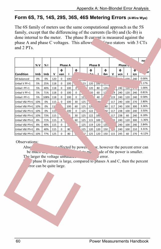
Form 6S, 7S, 14S, 29S, 36S, 46S Metering Errors (4-Wire Wye)
The 6S family of meters use the same computational approach as the 5S family, except that the differencing of the currents (Ia-Ib) and (Ic-Ib) is done internal to the meter. The phase B current is measured against the phase A and phase C voltages. This allows use of two stators with 3 CTs and 2 PTs.
% V % I Phase A Phase B Phase C non
Blondel
Condition Imb Imb V φ
van I φ
ian V φ
vbn I φ
ibn V φ
vcn I φ
icn% Error
All balanced 0% 0% 120 0 100 0 120 120 100 120 120 240 100 240 0.00%
Unbal V PF=1 5% 25% 118 0 100 0 123 120 100 120 119 240 120 240 1.17%
Unbal I PF=1 5% 40% 118 0 100 0 123 120 80 120 119 240 120 240 1.00%
Unbal V PF=1 5% 71% 118 0 100 0 123 120 60 120 119 240 120 240 0.81%
Unbal I PF=1 5% 108% 118 0 100 0 123 120 40 120 119 240 120 240 0.58%
Unbal V&I PF≠1 10% 0% 115 0 100 30 125 120 100 150 117 240 100 270 2.80%
Unbal V&I PF≠1 10% 0% 115 0 100 60 125 120 100 180 117 240 100 300 3.36%
Unbal V&I PF≠1 10% 0% 115 0 100 0 125 122 100 120 117 238 100 240 3.50%
Unbal V&I PF≠1 10% 73% 115 0 60 30 125 122 100 150 117 238 60 240 6.18%
Unbal V&I PF≠1 8% 71% 115 0 60 60 125 115 100 180 120 240 120 300 -1.36%
Unbal V&I PF≠1 8% 40% 115 0 80 60 125 119 120 120 120 240 100 240 2.84%
Unbal V&I PF≠1 8% 40% 115 0 80 30 125 120 120 150 120 240 100 210 3.31%
Unbal V&I PF≠1 10% 77% 125 0 80 60 117 125 120 150 115 245 60 270 -6.12%
Observations: Absolute error is not affected by power factor, however the percent error can
be much larger because the absolute magnitude of the power is smaller. The larger the voltage unbalance the larger the error. If the phase B current is large, compared to phases A and C, then the percent
error can be quite large.
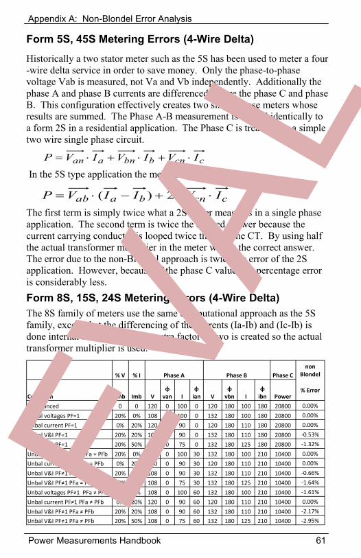
Appendix A: Non-Blondel Error Analysis
Power Measurements Handbook 61
Form 5S, 45S Metering Errors (4-Wire Delta) Historically a two stator meter such as the 5S has been used to meter a four-wire delta service in order to save money. Only the phase-to-phase voltage Vab is measured, not Va and Vb independently. Additionally the phase A and phase B currents are differenced, as are the phase C and phase B. This configuration effectively creates two single phase meters whose results are summed. The Phase A-B measurement is treated identically to a form 2S in a residential application. The Phase C is treated like a simple two wire single phase circuit.
ccnbbnaan IVIVIVP
In the 5S type application the meter measures:
ccnbaab IVIIVP *2)(The first term is simply twice what a 2S meter measures in a single phase application. The second term is twice the desired answer because the current carrying conductor is looped twice through the CT. By using half the actual transformer multiplier in the meter we get the correct answer. The error due to the non-Blondel approach is twice the error of the 2S application. However, because of the phase C value, the percentage error is considerably less. Form 8S, 15S, 24S Metering Errors (4-Wire Delta) The 8S family of meters use the same computational approach as the 5S family, except that the differencing of the currents (Ia-Ib) and (Ic-Ib) is done internal to the meter. No extra factor of two is created so the actual transformer multiplier is used.
% V % I Phase A Phase B Phase C non
Blondel
Condition Imb Imb V φ
van I φ
ian V φ
vbn I φ
ibn Power % Error
All balanced 0 0 120 0 100 0 120 180 100 180 20800 0.00%
Unbal voltages PF=1 20% 0% 108 0 100 0 132 180 100 180 20800 0.00%
Unbal current PF=1 0% 20% 120 0 90 0 120 180 110 180 20800 0.00%
Unbal V&I PF=1 20% 20% 108 0 90 0 132 180 110 180 20800 -0.53%
Unbal V&I PF=1 20% 50% 108 0 75 0 132 180 125 180 20800 -1.32%
Unbal voltages PF≠1 PFa = PFb 20% 0% 108 0 100 30 132 180 100 210 10400 0.00%
Unbal current PF≠1 PFa = PFb 0% 20% 120 0 90 30 120 180 110 210 10400 0.00%
Unbal V&I PF≠1 PFa = PFb 20% 20% 108 0 90 30 132 180 110 210 10400 -0.66%
Unbal V&I PF≠1 PFa = PFb 20% 50% 108 0 75 30 132 180 125 210 10400 -1.64%
Unbal voltages PF≠1 PFa ≠ PFb 20% 0% 108 0 100 60 132 180 100 210 10400 -1.61%
Unbal current PF≠1 PFa ≠ PFb 0% 20% 120 0 90 60 120 180 110 210 10400 0.00%
Unbal V&I PF≠1 PFa ≠ PFb 20% 20% 108 0 90 60 132 180 110 210 10400 -2.17%
Unbal V&I PF≠1 PFa ≠ PFb 20% 50% 108 0 75 60 132 180 125 210 10400 -2.95%
www.PowerMeasurements.com
The Power Measurements website provides a wealth of information for the metering community. Much of the information has been created by Bill Hardy but we welcome content submissions from the entire community. So if you have a document that would be useful to the community, send it to
[email protected] Here are some of the resources you’ll find here: Calendar of events of interest to metering community
Meter Schoo;s Conferences Standards Meetings
The Library ANSI Standards
Committees and Subcommittees Standards Status Notes from Latest Meeting
OIML Links and Documents Recent Presentations Made at Meter Schools Basic Metering Information
Metering Application Tech Bulletins Technical Papers EXCEL Analysis Models
William (Bill) Hardy, PhD is an internationally recognized authority on power measurement. He serves on the ANSI C12 Standards Committee and chairs several subcommittees including the committees writing standards for field testing, power measurement under non-sinusoidal conditions and harmonization of US and international standards. He is a popular teacher at many meter schools.
Power Measurements Handbook