Embed Size (px)
Citation preview

http: //www.sanwa-meter.co. jp
2006First Edition
From Tokyo Japan since 1941
SANWA ELECTRIC INSTRUMENT CO., LTD.
Dempa Bldg,4-4 Sotokanda2-Chome,Chiyoda-Ku,Tokyo 101-0021 JapanTel:+81-3-3251-0941 Fax:+81-3-3256-9740www.sanwa-meter.co.jp Specifications and extemal appearance of the product described adovemay be revised for modification without prior notice.
Distributed by
GENERAL CATALOGDigital Multimeter, Clamp Meter, Insulation Resistance Tester,Analog Multitester, Various Instruments, Accessories
2006 GENERAL CATALOG
06-01
●The specifications and design listed on this catalog are subject to change without notice. Printed photos may appear a little different from the actual color of products.
●Read the operation manual thoroughly and use equipment properly. ●The size of photos of products are not same as of actual product size.
Earth Tester, Thermo Meter.....P28-29
Exposition of earth tester....P28
Exposition of thermo meter....P29
Accessory mapping....P36Exposition of analog multitester....P23�
Analog Multitester comparative chart....P47
Exposition of digital multimeter.....P06�
Digital Multimeter comparative chart.....P42
CD721.....P09
CD721NH.....P09
CD731.....P09
CD750P.....P10
CD751.....P09
CD800a.....P10
DA32.....P10
DA-50C.....P10
KB-LAN.....P04
RD700.....P09
RD701.....P09
PC20.....P08
PC500.....P08
PC5000.....P07
PC510.....P08
PC520M.....P07
PC Link....P04
PC Link Plus.....P04
PM3.....P11
PM7a.....P11
PM10.....P11
PS8a.....P11
Exposition of clamp meter....P12�
Clamp Meter comparative chart....P45
CAM600S.....P14
DCL10.....P13
DCL20R.....P15
DCM60L.....P13
DCM2000.....P13
DCM400.....P13
DCM400AD.....P14
DCM2000AD.....P14
DCM-22AD.....P14
DCM2000R.....P15
DLC-330L.....P15
DLC-400A.....P15
AP33.....P27
AU-31.....P25
AU-32.....P25
CP-7D.....P27
CX506a.....P24
EM7000.....P24
PW-100Fb.....P27
SH-88TR.....P25
SP-18D.....P26
SP20.....P26
SP21.....P26
TA55.....P26
VS-100.....P27
YX360TRF......P25
YX-361TR.....P24
PDR-200DG.....P28 PDR-301.....P28
Test Lead,High Voltage Probe......P38
HV-10.....P38HV-20.....P38HV-50.....P38HV-60.....P38TL-100-OM.....P38TL-21.....P38TL-21M.....P38TL-507.....P38TL-508S.....P38
TL-61.....P38TL-82.....P38TL-84.....P38TL-88.....P38TL-91.....P38TL-91M.....P38TL-95.....P38TL-M54.....P38
Clip Adapter, Clip Lead, AC Adapter, Optical Link,
PC Link PLUS / PC Link......P39
AD-72AC......P39CL-11.....P39CL-13.....P39CL-15.....P39CL-506......P39KB-LAN.....P39 KB-RS1.....P39
KB-RS2.....P39KB-USB1....P39 KB-USB2....P39 PC Link.....P39PC Link Plus.....P39TL-8IC.....P39
Temperature Sensor.....P40K-1000...P40K-250PC...P40K-600...P40K-8-250...P40K-8-300...P40K-8-500...P40
K-8-650...P40K-8-800...P40K-AD...P40T-300PC...P40T-450...P40T-THP...P40
Carrying Case, Holster.....P41C-C7....P41C-CA....P41C-CD....P41C-CDS....P41C-CL....P41C-CP....P41C-DA....P41
C-NH7....P41C-PC10/S....P41C-SP....P41C-SPH....P41C-YS....P41H-50....P41H-70....P41
STH-1200.....P29
STH-500.....P29
STH-500C.....P29
TH3.....P29
Optical /Laser Power Meter.....P31�
Exposition of optical /Laser power meter.....P31
LP1....P32
OPM35S....P32
OPM-360....P32
OPM36M....P32
OPM37LAN....P31
OPM-570L....P32
OPM-572....P33
OPM-572MD...P33
Cord Tester.....P33
CAD-2L....P33
CAD-3L....P33
CS-10VB....P33
Tachometer, Speed Meter.....P34
SE-100.....P34
SE-200.....P34
SE-9000.....P34
SE-9000M.....P34
Calibrator.....P35
STD-2000.....P35 STD5000M.....P35
AD-72AC......P39AP33.....P27AU-31.....P25AU-32.....P25
CAD-2L....P33CAD-3L....P33CAM600S.....P14C-C7....P41C-CA....P41C-CD....P41C-CDS....P41C-CL....P41C-CP....P41CD721.....P09CD721NH.....P09CD731.....P09CD750P.....P10CD751.....P09CD800a.....P10C-DA....P41CL-11.....P39CL124.....P16CL-13.....P39CL140.....P17CL-15.....P39CL-20D.....P17CL-22AD.....P17CL33DC.....P17CL-506......P39C-NH7....P41CP-7D.....P27C-PC10/S....P41CS-10VB....P33C-SP....P41C-SPH....P41CX506a.....P24C-YS....P41
DA32.....P10DA-50C.....P10 DCL10.....P13DCL20R.....P15DCM60L.....P13DCM2000.....P13DCM400.....P13DCM400AD.....P14DCM2000AD.....P14DCM-22AD.....P14DCM2000R.....P15DG251.....P20DG525.....P20DG6.....P19DG7.....P19DG8.....P19DG9.....P19DLC-330L.....P15DLC-400A.....P15DM1008S.....P21DM-1527.....P22DM1528S.....P21DM-5257.....P22DM508S.....P21DM5218S.....P21
EM7000.....P24
H-50....P41H-70....P41HV-10.....P38HV-20.....P38HV-50.....P38HV-60.....P38
K-1000...P40K-250PC...P40K-600...P40K-8-250...P40K-8-300...P40K-8-500...P40K-8-650...P40
K-8-800...P40K-AD...P40KB-LAN.....P04/39KB-RS1.....P39KB-RS2.....P39KB-USB1....P39 KB-USB2....P39
LP1....P32LS-10.....P17
M53.....P20
OPM35S....P32OPM-360....P32OPM36M....P32OPM37LAN....P31OPM-570L....P32OPM-572....P33OPM-572MD...P33
PC20.....P08PC500.....P08PC5000.....P07PC510.....P08PC520M.....P07PC Link....P04/39PC Link Plus
.....P04/39PDM508S.....P22PM3.....P11PM7a.....P11PM10.....P11PS8a.....P11PW-100Fb.....P27
RD700.....P09RD701.....P09
SE-100.....P34SE-200.....P34SE-9000.....P34SE-9000M.....P34SH-88TR.....P25SP-18D.....P26SP20.....P26SP21.....P26STD-2000.....P35STD5000M.....P35 STH-1200.....P29STH-500.....P29STH-500C.....P29
TA55.....P26TH3.....P29TL-100-OM.....P38TL-21.....P38TL-21M.....P38TL-507.....P38TL-508S.....P38TL-61.....P38TL-82.....P38TL-84.....P38TL-88.....P38TL-91.....P38TL-91M.....P38TL-95.....P38TL-M54.....P38TL-8IC.....P39T-300PC...P40T-450...P40T-THP...P40
VS-100.....P27
YX360TRF......P25YX-361TR.....P24
Exposition of clamp sensor....P16
CL124.....P16
CL140.....P17
CL-20D.....P17
CL-22AD.....P17
CL33DC.....P17
LS-10.....P17
Exposition of insulation resistance tester....P18�
Insulation Resistance Tester comparative chart....P46
DG251.....P20
DG525 .....P20
DG6.....P19
DG7.....P19
DG8.....P19
DG9.....P19
DM1008S.....P21
DM-1527.....P22
DM1528S.....P21
DM-5257.....P22
DM508S.....P21
DM5218S.....P21
M53.....P20
PDM508S.....P22
Digital Multimeter
Analog Multitester
page
04page
23Clamp Meter,Insulation ResistanceTester page
12Various Instruments
page
28page
36Accessories
2006 GENERAL CATALOG
A
C
L
M
O
P
DR
S
T
E
H
KV
Y
02 03http://www.sanwa-meter.co.jp
Dig
ital
Mu
ltim
eter
An
alo
g M
ult
ites
ter
Cla
mp
Met
er,
Insu
latio
n R
esis
tanc
e Te
ster
Vari
ous
Inst
rum
ents
Acc
esso
ries

PC20 / LAN adds comfort to the measurement environment.The PC20 / LAN is an economical package product that includes, digital multimeter "PC20", Ethernet adapter "KB-LAN", and software "PC LINK PLUS". This complete set allows the digital multimeter "PC20" to be used on an Ethernet LAN. PC20 / LAN revolutionizes your measurement environment.
A wide variety of applications ranging from business and educational institutions to personal users.
The PC Link system is the software dedicated to a PC for retrieving data outputted from a SANWA digital multimeter(PC series). The operation screen displays graphs in real time to allow you to check changes in measured values(voltage, current, etc.)with ease. Measured data can be saved on a CSV file, so it is easily processed on Excel. The ease of use in a variety of applications from data retrieval, processing and analy-sis holds this system in high esteem, resulting in its extensive accep-tance for business, education and personal use.
LAN is a network connected to terminals of PCs and printers in a same building via UTP cables so as to allow for the sending, receiving and shar-ing of data. As LANs are constructed in ordinary homes today, not to men-tion offices, factories, and educational institutes such as universities, envir-onments that allow for monitoring of measurement results at remote places are essential. PC20 / LAN can be used over the Ethernet(on the LAN)to support the measurement environment in the network era.
When connected to the LAN:When a digital multimeter(PC series)is directly connected to a PC using a RS232C / USB cable, the distance between measuring and monitoring places is limited(approximately 15 to 13m). In the meanwhile, in an environment where a LAN is established, measurement results can be monitored and recorded from every PC on the LAN.
Major features :・ Automatically detects a port connected with a digital multimeter (except the case of LAN connection).・ The retrieval interval can be set from 1 second.・ Allows viewing the previous screen while retrieving data.・ Allows automatic retrieval by schedule setting.・ Allows data saving in a CSV format with the date and time appended.・ The Y axis of a graph can be divided into 10.・ Allows automatic e-mail transmission attached with measure-
ment data(Outlook Express Ver.6 and higher).・ Allows data import to Excel in up to 65,536 lines.
OS : Windows98 / 98SE / ME / 2000 / XP* KB-LAN(LAN adapter)can be used only with Windows2000 / XP. WindowsNT4.0 is not supported.
CPU : Pentium・450MHz or betterMemory : 128MB or better(for 8 channels logging)Resolution : 800×600 or above
PC20/LAN PC20/LAN allows for the centralized control of digital multimeter on the LAN by a PC.
PC Link System
Example of PC20+KB-LAN Connection
Screen viewed from web browser
Example of PC Link Plus screen
PC Link Plus Max 8 Channels
PC Link Single Channel
Enhanced operation efficiency by means of data retrieval software, PC Link Plus, which can handle measurements for up to a maximum of 8 channels.
PC20, PC500, PC510, PC520M, PC5000
PC Link Plus operating environment
Applicable Models
Optional accessories for PC Link products
■ The latest version of PC Link Plus is Ver2.10.(March, 2005)■ Free version-up service is available in our website.
http://www.sanwa-meter.co.jp/
LAN operations support extensive measurement environments.
TCP / IP is a collection of protocols(rules and pro-cedures)for communication on the Internet and LAN. Each PC is given an individual address(e.g. 192.168.0.1)on the LAN. An address number is also given to a digital multimeter, which is recog-nized as one of the terminals on the LAN. When this address is typed in the address bar on the web browser(IE, etc.)introduced to your PC, the meas-urement results can be monitored from each PC on the LAN.
* An IP address can be obtained by automatic acquisition or by manual setting. * For data saving, PC Link Plus is required(sold separately). * You can customize the Web screen in an environment that allows for Java
programming.
You can monitor the measurement environment on your web browser.
A digital multimeter set at a certain measuring point concurrently monitors and measures various factors such as voltage, current and frequency on up to 8 channels(with the use of PC Link Plus). RS232C, USB or LAN cable can be used to allow flexible con-nection between a digital multimeter and a PC.Concurrent measurements can be made even in an environment with various interfaces mixed.
* PC connecting cable is available as an option.
Flexible support for diversified environments
* English version is also available.
KB-RS2Optical link RS-232C
KB-RS1Optical link RS-232C
KB-USB1Optical link USB
AD-72AC(220V)AC adapter
KB-USB2Optical link USB
KB-LANLAN adapter
For PC5 series For PC20
Monitoring by PC on the LAN
●HUB
●HUB
LANMeasurement Field Monitoring Field
HUB●�
HUB●�
■PC20 / LAN(Package Product)
・ PC20 ・ Test Lead(TL-21) ・ KB-LAN(LAN Adapter)・ AC Adapter for KB-LAN・ CL-11(Clip Adapter) ・ Instruction Manual
■KB-LAN�
・ KB-LAN(LAN Adapter)・ AC Adapter for LAN Adapter・ Instruction Manual
Current value LAN Connection
LAN Connection
(PC20+KB-LAN)�
Frequency
(PC20+KB-LAN)�
LAN Connection
Temperature
(PC20+KB-LAN+Temperature Probe)�
●HUB
Concurrent�measurements
Frequency
(PC20+KB-LAN)�
PC520Mstand alone logging
PC520M
LAN
Current value
Current value
Resistancevalue
LAN connection
LANconnection
Data download
USB connection
(PC20+KB-LAN)� (PC5 series or PC20)�
RS232C connection
●HUB
HUB●�
HUB●�
●HUB
HUB●�
04 05http://www.sanwa-meter.co.jp http://www.sanwa-meter.co.jp

Measuring range Best accuracyFunction Input�impedance
10M�
Resolution
Bandwidth �
Fuse / Battery ��
Size / Weight �Standard�accessories�included
40Hz~20kHz(below 500V)40Hz~1kHz(ACA) �
12.5A/500V IR20kA φ6.3×32�0.63A/250V IR1.5kA φ5.2×20�
H179×W87×D55mm/460g(including holster)�
Test lead(TL-82), Holster(H-50), Thermocouple K type(K-250PC), �Clip adapter(CL-13), Instruction manual
6LF22(9V)×1
Digital Multimeters
1.
2.
3.
A digital multimeter is a convenient measuring instrument that allows by itself the measurement of DC voltage, AC voltage, DC current, AC current and resistance(Pocket type DMM normally cannot be used for the measurement of current for safety reasons).In addition to these basic measuring functions, most models are provided with features such as a diode test function and con-tinuity buzzer. Some of recent products feature the measure-ment of frequency and capacitor capacity. Some have added functions of maximum and minimum value hold and relative val-ue measurement as well as data hold and range hold functions. The advent of DMMs(PC series)connectable to a PC makes it possible to let a PC assume the function of expensive recording meters and recorders.
1. What are the necessary measuring functions?Choose the necessary functions, except voltage and resistance measurement.(including need for the measurement of current(400mA, 10A, 12A, 20A), ca-pacitor, frequency, temperature and measurement of 4-20mA, etc.)�
2. Other necessary functionsFunctions required differ depending on where the measurement is taken.
1) To record measured values concurrently with the process of measurement→ To fix data by the data hold function.→ To secure the test lead in the holster.
2) To check changes in measured values→ Measurement of maximum values, minimum val-ues, and relative values.
3. For measurements of waveforms of non-sine waves, choose a model supporting measurements by RMS values.In measuring distorted sine and non-sine waves(sq-uare wave, triangular wave, pulse), significant errors occur in measurement by models making measure-ments by mean values.
There are two types of RMS values.AC-Coupled true RMS value : Adapted to measure-ments of distorted sine and non-sine waves of the ACAC + DC-coupled true RMS value : Adapted to meas-urements of waveform containing a DC component.
4. Other functionsThere are other types including a function to transfer data during measurement to a PC in real time and a function to record measured data in a built-in memory. To transfer data to a PC, optional connecting cables and data retrieval software(PC Link or PC Link Plus)are required in addition to a DMM of PC series.
Highly accurate measurement. Higher accuracy(1% or less)compared with an analog multimeter(approximately 3%).
Reduced measuring loss due to high internal impedance(low voltage drop between terminals).
No reading error. No parallax error and reading error by a user as occurs with an analog multimeter.
What is Digital Multimeter?
Four key pointsin choosing a suitable model
Advantages of digital multimeters(DMMs)�
Measurement
AnodeCathode
Diode
V
Object to be measured(dry cell, resistor, etc.)�
Power source
DCV measurement
ACV measurement
mA
LoadPower source
Voltage, Resistance measurement
Current measurement
Diode test
In making measure-ments, connect your DMM in parallel with an object to be measured. Do not apply signals ex-ceeding the maxi-mum rated input vol-tage.
In making measure-ments, connect your DMM in series with an object to be measured.Do not apply signals exceeding the maxi-mum rated input cur-rent.
When the black test lead is connected to the cathode side of the diode and the red test lead to the anode side, the forward voltage can be measured. In contrast, if the black test lead is connected to the anode side of the diode and the red test lead to the cath-ode side, the reverse voltage can be meas-ured and "OL" display appears.
High accuracy & high resolution(PC Link)
Measuring range Best accuracyFunction Input�impedance
10MΩ�±(0.03%+2)�
±(0.8%+60)�
±(0.1%+20)�
±(1.0%+40)�
±(0.2%+6)�
±(0.8%+3)�
±(0.002%+4)�
±(0.002%+4)�
±(3d / kHz+2)�
±(0.25dB+2)�
±25d
Resolution
0.01mV�
0.01mV�
0.01μA�
0.01μA�
0.01Ω�
0.01nF�
0.0001Hz�
0.0001Hz�
�
�
0.01%
Bandwidth �
Fuse �
Battery �
Size / Weight �Standard�accessories�included
V : 45Hz~1kHz 1kHz~20kHz(below 500V), A : 45Hz~1kHz �
12.5A/500V IR20kA φ6.3×32 0.63A/250V IR1.5kA φ5.2×20 �
6LF22(9V)×1 �
H179×W87×D55mm / 460g(including holster) �
Test lead(TL-82), Holster(H-50), Clip adapter(CL-13), �Instruction manual
DCV�
ACV�
DCA�
ACA�
Resistance�
Capacitance�
Frequency�
Logic frequency�
Duty cycle�
dBm�
4~20mA%�
Continuity�
Diode test
DCV�
ACV�
DCA�
ACA�
Resistance�
Capacitance�
Temperature�
Frequency�
Continuity�
Diode test
500m/5/50/500/1000V�
500m/5/50/500/1000V�
500μ/5m/50m/500m/5/10A�
500μ/5m/50m/500m/5/10A�
500/5k/50k/500k/5M/50M�
50n/500n/5μ/50μ/500μ/9999μF�
5Hz~200kHz�
5Hz~2MHz�
0.1%~99.99%�
-11.76dBm~54.25dBm at 600Ω�
4mA=0%, 20mA=100%�
Buzzer sounds at between 20Ω and 200Ω. Open voltage : approx. 3V�
Open voltage : approx. 3.5V
±(0.08%+2)�
±(0.5%+3)�
±(0.2%+4)�
±(0.6%+3)�
±(0.2%+2)�
±(0.8%+3)�
±(0.3%+3)�
±(0.01%+2)�
0.01mV�
0.01mV�
0.1μA�
0.1μA�
0.01Ω�
0.01nF�
1℃�
0.001Hz
50m/500m/5/50/500/1000V�
50m/500m/5/50/500/1000V�
500μ/5m/50m/500m/5/10A�
500μ/5m/50m/500m/5/10A�
50/500/5k/50k/500k/5M/50M�
50n/500n/5μ/50μ/500μ/9999μF�
-50℃~1000℃(thermocouple K type)�
5Hz~125kHz�
Buzzer sounds at between 20Ω and 120Ω. Open voltage : approx. 3V�
Open voltage : approx. 3.5V
Optional accessories
Optional accessories
Software : PC Link , PC Link Plus�Optical PC link cable : KB-RS2 , KB-USB2�Clamp probe : CL124, CL140, CL-20D, CL-22AD, CL33DC�Temperature probe : T-300PC(PC Link software will be necessary to use.)�Test lead : TL-21M�Carrying case : C-CD
High accuracy & built-in memory(PC Link)
43,000 points data logging in built-in memory
■4-4 / 5 digits 50000 count � (Selectable 5-4 / 5 digits 500000 count for DCV & Hz)�■0.03% best accuracy �■AC / AC + DC True RMS �■Fast speed bar graph �■Capacitance measurement(5000 count) � ※Not suitable for measurement of condensers with large leak current. �■4-20mA% measurement �■dBm 20 selectable reference impedance �■Line frequency(AC sine wave)measurement�■Logic frequency measurement�■Duty cycle measurement�■Capture(peak hold) 0.8ms in duration�■MAX, MIN, MAX-MIN recording mode�■Peak hold�■Data hold, Range hold�■Relative value�■Auto power off(17min.)(cancelable)�■Alarm for improper test lead insertion to current terminal�■Protective holster with wall hanger and lead holder�■Tilt stand�■Optical link RS232C / USB interface(optional)�
Display : numeral display 50000 & 500000 selectable� Bar graph 52 segments�Sampling rate : 5 times / sec. for 50000 count numer-al display , 1.25 times / sec. for 500000 count numer-al display 60 times / sec. for bar graph�Bandwidth : V : 45Hz~1kHz, 1kHz~20kHz(below 500V),� A : 45Hz~1kHz �Safety : IEC61010-1(EN61010-1) 2001-02 CAT.Ⅲ 600V � Max. / CAT.Ⅱ1000V Max.�Battery life : Approx. 120h(alkaline battery)at DCV range
Software : PC Link, PC Link Plus�Optical PC link cable : KB-RS2, KB-USB2�Clamp probe : CL124, CL140, CL-20D, CL-22AD, CL33DC�Temperature probe : T-300PC(PC Link software will be necessary to use.), �
K-8-250~800�K type adapter : K-AD�Test lead : TL-21M�Carrying case : C-CD
PC520M
50000 & 500000 Count
PC5000
■3-4 / 5 digits 5000 count�■0.08% best accuracy ■AC True RMS �■Fast speed bar graph�■Capacitance measurement� ※Not suitable for measurement of condensers with large leak current. �■K type temperature -50℃~1000℃� ※Optional accessory K-AD is necessary.� ※K type temp. sensor K-250PC is included as a standard accessory.�■Frequency measurement(AC sine wave only)�■Data hold / Range hold�■Auto power off(17min.)(cancelable)�■Test lead resistance zero adjustment function�■Alarm for improper test lead insertion to current terminal�■Protective holster with wall hanger and lead holder�■Tilt stand�■Optical link RS232C / USB interface(optional)�
Data Logging Mode�■43,000 data points in built-in memory�■Selection of measurement inerval� 0.05s/1s/20s/40s/1min/2min/4min/8min� (DCV, ACV, DCA, ACA)� 0.2s/1s/20s/40s/1min/2min/4min/8min(℃, Ω)� 0.4s/1s/20s/40s/1min/2min/4min/8min(Hz)�■Auto-standby mode during data logging to extend battery life�■Auto-stop of data logging when batteries are low to guarantee accuracy of every logged datum�■Export logged data to PC�
Display : numeral display 5000 , bar graph 52 segments�Sampling rate : 5 times / sec., 60 times / sec. for bar graph�Bandwidth : 40Hz~20kHz(below 500V), 40Hz~1kHz(ACA)Safety : IEC61010-1(EN61010-1)2001-02 CAT.Ⅲ 600V � Max. / CAT.Ⅱ1000V Max.�Battery life : Approx. 150h(alkaline battery)at DCV range
Optional
Dig
ital
Mu
ltim
eter
Optional
06 07http://www.sanwa-meter.co.jp http://www.sanwa-meter.co.jp

Clamp probe : CL124, CL140, CL-20D, CL-22AD, CL33DC�Temperature probe : K-8-800, K-8-650, K-8-300, K-8-500, K-8-250�K type adapter : K-AD�Test lead : TL-21M Carrying case : C-CD Clip adapter : CL-13
Multi-function
Standard
RD700RD701
CD751
CD721
CD721NH(CD721 without holster)�
RD700
■3-3 / 4 digits 4000 count ■0.3% best accuracy�■AC True RMS ※RD701 only�■Capacitance measurement� ※Not suitable for measurement of condensers with large leak current.�■K type temperature� ※Optional accessory K-AD is necessary.� ※K type temp. sensor K-250PC is included as a standard accessory�■Frequency measurement� ※Input voltage : 20VACrms and under � ※Input signal : sign wave or square wave with 40%-70% duty � ※Input sensitivity : 10Hz~20kHz/0.9Vrms and above �
: 20kHz~500kHz/2.6Vp or 1.9Vrms and above � : 500kHz~1MHz/4.2Vp or 3Vrms and above �
■ADP function(for current sensor) �■Max recording measurement �■Data hold / Range hold ■Relative value �■Auto power off(30min.)(cancelable)�■Alarm for improper test lead insertion to current terminal �■Protective holster with wall hanger and lead holder �■Tilt stand�
Display : numeral display 4000(Hz : 9999, capacitance : 5000)�
Sampling rate : 3 times / sec.(Hz : 2 times / sec.)�
Bandwidth : 50~500Hz�
Safety : IEC61010-1(EN61010-1)2001-02 CAT.Ⅲ 600V Max. / �
CAT.Ⅱ1000V Max.
High input impedance 1000M�
CD751CD731CD721CD721NH
CD751
RD700 / 701
Common features�■3-3 / 4 digits 3200 count�■0.5% best accuracy�■Analog bar graph�■Data hold / Range hold�■Protective holster with wall hanger and lead holder(except CD721NH)�
CD751 / CD731�■AC + DC True RMS ※CD751�■Micro-current range 32μ/320・3200μA�■Large-current 20A range�■Safety cover for the 20A terminal�■Auto power save(10min.)※CD751�■Auto power off(10min.)※CD731�■Tilt stand�
CD721 / CD721NH�■12A range�■Battery check(1.5V)�■Auto power off(10min.)�■Safety cap for the 12A terminal�
Display : numeral display 3200, bar graph 32 segments�Sampling rate : 2 times / sec. for numeral display, � 12 times / sec. for bar graph�Bandwidth :�CD751 : 40~500Hz(3.2V range), �
40~1kHz(higher than 32V range)�
CD731 / CD721 / CD721NH : 40~400Hz�
Safety : IEC61010-1(EN61010-1)2001-02 CAT.Ⅲ600V � Max. / CAT.ⅡDC1000V, AC750V Max.
Choice of standard models
High accuracy & multi-function(PC Link)�
High accuracy (PC Link)�
Temperature measurement, True RMS
■3-4 / 5 digits 5000 count ■0.08% best accuracy�■AC True RMS�■High speed bar graph ※Zoom bargraph(5 times)�■Capacitance measurement� ※Not suitable for measurement of condensers with large leak current.�■K type temperature -50℃~1000℃� ※Optional accessory K-AD is necessary.� ※K type temp. sensor K-250PC is included as a standard accessory.�■Frequency measurement(AC sine wave only)�■MAX-MIN recording mode ■Peak hold�■Data hold / Range hold ■Relative value�■Auto power off(17min.)(cancelable)�■Test lead resistance zero adjustment function�■Alarm for improper test lead insertion to current terminal�■Protective holster with wall hanger and lead holder�■Tilt stand�■Optical link RS232C / USB interface(optional)�
Display : numeral display 5000, bar graph 52 segments�Sampling rate : 5 times / sec., 60 times / sec. for bar graph�Bandwidth : 40Hz~20kHz(below 500V), 40Hz~1kHz (ACA)Safety : IEC61010-1(EN61010-1)2001-02 CAT.Ⅲ 600V � Max. / CAT.Ⅱ1000V Max.�Battery life : Approx. 120h(manganese battery)at DCV range
PC510
Best accuracy 0.08% high accuracy model
■3-4 / 5 digits 5000 count�■0.08% best accuracy�■High speed bar graph�■Capacitance measurement� ※Not suitable for measurement of condensers with large leak current.�■Frequency measurement(AC sine wave only)�■Data hold / Range hold�■Auto power off(17min.)(cancelable)�■Alarm for improper test lead insertion to current terminal�■Protective holster with wall hanger and lead holder�■Tilt stand�■Optical link RS232C / USB interface(optional)�
Display : numeral display 5000, bar graph 52 segments�Sampling rate : 5 times / sec., 60 times / sec for bar graph�Bandwidth : 40~20kHz(below 500V), 40~1kHz (ACA)�Safety : IEC61010-1(EN61010-1)2001-02 CAT.Ⅲ 600V Max. / � CAT.Ⅱ 1000V Max.�Battery life : Approx. 120h(manganese battery)at DCV range
PC500
Data processing (PC Link). Ethernet LAN adapter connectable
AC adapter connectable for long haul measurement
■3-3 / 4 digits 4000 count�■0.5% best accuracy�■Capacitance measurement� ※Not suitable for measurement of condensers with large leak current.�■Data hold / Range hold�■Safety cover for the 4・10A terminal�■Safety cap for AC adapter terminal�■Protective holster with wall hanger and lead holder�■Tilt stand�■Optical link RS232C / USB interface(optional)�■Ethernet connection(optional)� ※Economical package prodcut PC20 / LAN is also available.�
Display : numeral display 4000�Sampling rate : 3 times / sec. �Bandwidth : 40~500Hz�Safety : IEC61010-1(EN61010-1)2001-02 CAT.Ⅲ 600V Max. / CAT.Ⅱ DC1000V, 750V Max.�With AC adapter : IEC61010-1(EN61010-1) 2001-02 CAT.Ⅲ � 200V Max.
PC20
Measuring range Best accuracyFunction Input�impedance
10MΩ�±(0.08%+2)�
±(0.5%+3)�
±(0.2%+4)�
±(0.6%+3)�
±(0.2%+2)�
±(0.8%+3)�
±(0.3%+3)�
±(0.01%+2)�
6LF22(9V)×1
6LF22(9V)×1
R6×2
Resolution
0.01mV�
0.01mV�
0.1μA�
0.1μA�
0.01Ω�
0.01nF�
1℃�
0.001Hz
Bandwidth �
Fuse / Battery � �
Size / Weight �Standard�accessories�included
40Hz~20kHz(below 500V) 40Hz~1kHz(ACA)�
12.5A/500V IR20kA φ6.3×32�0.63A/250V IR1.5kA φ5.2×20�
H179×W87×D55mm/460g(including holster)�
Test lead(TL-82), Holster(H-50), Thermocouple K type(K-250PC), �Instruction manual
DCV�
ACV�
DCA�
ACA�
Resistance�
Capacitance�
Temperature�
Frequency�
Continuity�
Diode test
50m/500m/5/50/500/1000V�
50m/500m/5/50/500/1000V�
500μ/5m/50m/500m/5/10A�
500μ/5m/50m/500m/5/10A�
50/500/5k/50k/500k/5M/50M�
50n/500n/5μ/50μ/500μ/9999μF�
-50℃~1000℃(thermocouple K type)�
5Hz~125kHz�
Buzzer sounds at between 20Ω and 120Ω. Open voltage : approx. 3V�
Open voltage : approx. 3.5V
Measuring range Best accuracyFunction Input�impedance
10M~�1000M�
±(0.3%+4)�
±(1.5%+5)�
±(1.2%+3)�
±(1.5%+4)�
±(0.6%+4)�
±(2.5%+6)�
±(2%+3)�
±(0.5%+4)�
Resolution
0.1mV�
0.1mV�
0.1μA�
0.1μA�
0.1Ω�
0.01nF�
1℃�
0.01Hz
DCV�
ACV �
DCA�
ACA �
Resistance�
Capacitance�
Temperature�
Frequency�
Continuity�
Diode Test
400m/4/40/400/1000V�
400m/4/40/400/1000V�
400μ/4000μ/40m/400m/4/10A�
400μ/4000μ/40m/400m/4/10A�
400/4k/40k/400k/4M/40M�
500n/5μ/50μ/500μ/3000μF�
-20℃~300℃�
50Hz~1MHz�
Buzzer sounds at between 20Ω and 120Ω. Open voltage : approx. 0.4V�
Open voltage : approx. 1.6V
Optional accessoriesSoftware : PC Link, PC Link Plus Optical PC link cable : KB-RS2, KB-USB2�Clamp probe : CL124, CL140, CL-20D, CL-22AD, CL33DC�Temperature probe : T-300PC(PC Link software will be necessary to use.), � K-8-250~800�K type adapter : K-AD Test lead : TL-21M Carrying case : C-CD Clip adapter : CL-13
Measuring range Best accuracyFunction Input�impedance
10MΩ�±(0.08%+2)�
±(0.5%+3)�
±(0.2%+4)�
±(0.6%+3)�
±(0.2%+2)�
±(0.8%+3)�
±(0.01%+2)�
Resolution
0.01mV�
0.01mV�
0.1μA�
0.1μA�
0.01Ω�
0.01nF�
0.001Hz
Bandwidth �
Fuse / Battery � �
Size / Weight �Standard�accessories�included
40Hz~20kHz(below 500V) 40Hz~1kHz(ACA)�
12.5A/500V IR20kA φ6.3×32�0.63A/250V IR1.5kA φ5.2×20�
H179×W87×D55mm/460g(including holster)�
Test lead(TL-82), Holster(H-50), Instruction manual
DCV�
ACV�
DCA�
ACA�
Resistance�
Capacitance�
Frequency�
Continuity�
Diode Test
50m/500m/5/50/500/1000V�
50m/500m/5/50/500/1000V�
500μ/5m/50m/500m/5/10A�
500μ/5m/50m/500m/5/10A�
50/500/5k/50k/500k/5M/50M�
50n/500n/5μ/50μ/500μ/9999μF�
5Hz~125kHz�
Buzzer sounds at between 20Ω and 120Ω. Open voltage:approx. 3V�
Open voltage : approx. 3.5V
Optional accessoriesSoftware : PC Link, PC Link Plus Optical PC link cable : KB-RS2, KB-USB2�Clamp probe : CL124, CL140, CL-20D, CL-22AD, CL33DC�Temperature probe : T-300PC(PC Link software will be necessary to use.)�Test lead : TL-21M Carrying case : C-CD Clip adapter : CL-13
Measuring range Best accuracyFunction Input�impedance
DCV:�10M~�100M�
ACV:10M�
�
�
�
±(0.5%+2)�
±(1.2%+2)�
±(1.5%+2)�
±(1.8%+2)�
±(1.2%+2)�
±(5%+6)�
Resolution
0.1mV�
0.001V�
0.1μA�
0.1μA�
0.1Ω�
0.01nF
Bandwidth �
Fuse / Battery � �
Size / Weight �Standard�accessories�included
40Hz~500kHz(below 500V) 40Hz~1kHz(ACA)�
0.5A/250V IR300A φ5.2×20�12A/250V IR500A φ6.3×30�
H167×W90×D48mm/330g(including holster)�
Test lead(TL-21), Holster(H-70), Instruction manual
DCV�
ACV�
DCA�
ACA�
Resistance�
Capacitance�
Continuity�
Diode test
400m/4/40/400/1000V�
4/40/400/750V�
400μ/4000μ/40m/400m/4A/10A�
400μ/4000μ/40m/400m/4A/10A�
400/4k/40k/400k/4M/40M�
40n/400n/4μ/40μ/100μF�
Buzzer sounds at between 10Ω and 120Ω. Open voltage : approx. 0.4V�
Open voltage : approx. 1.5V
Optional accessoriesSoftware : PC Link, PC Link Plus Optical PC link cable : KB-RS1, KB-USB1�Ethernet LAN adapter : KB-LAN�Clamp probe : CL124, CL140, CL-20D, CL-22AD, CL33DC�Temperature probe : T-300PC(PC Link software will be necessary to use.)�AC adapter : AD-71AC(100V), AD-72AC(220V)�Test lead : TL-21M Carrying case : C-PC10/S or C-C7 Clip adapter : CL-11, TL-8IC
R6P×2
Measuring range Best accuracyFunction Input�impedance
DCV:�10M~�100M�
ACV:�10M~�100M�
±(0.5%+2)�
±(1.2%+8)�
±(1.4%+2)�
±(1.8%+10)�
±(1.2%+2)�
Resolution
0.1mV�
0.001V�
0.01μA�
0.01μA�
0.1Ω�
Bandwidth �
Fuse / Battery � �
Size / Weight �Standard�accessories�included
40~500Hz(3.2V), 40~1kHz(higher than 32V)�
0.5A/250V IR 300A φ5.2×20mm�20A/250V IR 1000A ceramic �
H165.5×W78×D41.5mm/approx. 315g(including holster) �
Test lead(TL-21), Holster(H-70), Instruction manual
6LF22(9V)×1
Bandwidth �
Fuse / Battery � �
Size / Weight �Standard�accessories�included
50~500Hz�
12.5A/500V IR20kA φ6.3×32mm�0.63A/250V IR1.5kA φ5.2×20mm�
H179×W87×D55mm/460g(including holster)�
Test Lead(TL-82), Thermocouple K type(K-250PC), Holster(H-50), �Instruction manual
DCV�
ACV�
DCA�
ACA�
Resistance�
Continuity�
Diode test
320m/3.2/32/320/1000V�
3.2/32/320/750V�
32μ/320μ/3200μ/32m/320m/20A�
32μ/320μ/3200μ/32m/320m/20A�
320/3.2k/32k/320k/3.2M/30M�
Buzzer sounds at approx. 20Ω. Open voltage : approx. 1.3V�
Open voltage : approx. 3V
CD731
R6P×2
Measuring range Best accuracyFunction Input�impedance
DCV:�10M~�100M�
ACV:�10M~�100M�
±(0.5%+2)�
±(1.2%+5)�
±(1.4%+2)�
±(1.8%+5)�
±(1.2%+2)�
Resolution
0.1mV�
0.001V�
0.01μA�
0.01μA�
0.1Ω�
Bandwidth �
Fuse / Battery � �
Size / Weight �Standard�accessories�included
40~400Hz�
0.5A/250V IR 300A φ5.2×20mm�20A/250V IR 1000A ceramic �
H165.5×W78×D41.5mm/approx. 315g(including holster) �
Test lead(TL-21), Holster(H-70), Instruction manual
DCV�
ACV�
DCA�
ACA�
Resistance�
Continuity�
Diode test
320m/3.2/32/320/1000V�
3.2/32/320/750V�
32μ/320μ/3200μ/32m/320m/20A�
32μ/320μ/3200μ/32m/320m/20A�
320/3.2k/32k/320k/3.2M/30M�
Buzzer sounds at approx. 20Ω. Open voltage : approx. 1.3V�
Open voltage : approx. 3V
CD721/CD721NH
R6P×2
Measuring range Best accuracyFunction Input�impedance
DCV:�10M~�100M�
ACV:�10M~�100M�
±(0.5%+2)�
±(1.2%+5)�
±(1.4%+2)�
±(1.8%+5)�
±(1.2%+2)�
Resolution
0.1mV�
0.001V�
0.01μA�
0.01μA�
0.1Ω�
Bandwidth �
Fuse / Battery � �
Size / Weight �Standard�accessories�included
40~400Hz�
0.5A/250V IR 300A φ5.2×20mm�12A/250V IR 500A �
H165.5×W78×D41.5mm/approx. 315g(including holster), approx. 220g(CD721NH)�
Test lead(TL-21), Holster for CD721(H-70), Instruction manual�※No holster with CD721NH
DCV�
ACV�
DCA�
ACA�
Resistance�
Continuity�
Diode test
320m/3.2/32/320/1000V�
3.2/32/320/750V�
32m/320m/12A�
32m/320m/12A�
320/3.2k/32k/320k/3.2M/30M�
Buzzer sounds at approx. 20Ω. Open voltage : approx. 1.3V�
Open voltage : approx. 3V
Optional accessoriesClamp probe : CL124, CL140, CL-20D, CL-22AD, CL33DC�High voltage probe : HV-60�Test lead : TL-21M Carrying case : C-C7 Clip adapter : CL-11, CL-15, TL-8IC
Optional
RD701 only�
�
CD751onlyCD751only CD731/721/721NHCD721/721NH
Dig
ital
Mu
ltim
eter
Dig
ital
Mu
ltim
eter
Optional accessories
Optional
08 09http://www.sanwa-meter.co.jp http://www.sanwa-meter.co.jp

Optional accessoriesClip adapter : CL-13
Optional accessoriesClip adapter : CL-11, TL-8IC
Optional accessoriesClip adapter : CL-11, TL-8IC
Optional accessoriesClip adapter : CL-13
Pocket type
PM3
■3-3 / 4 digits 4000 count�■0.7% best accuracy�■Capacitance measurement� ※Not suitable for measurement of condensers with large leak current.�■Frequency measurement(AC sine wave only)�■Duty cycle�■Data hold�■Relative value�■Auto power off(15min.)(cancelable)�
Display : numeral display 4000�Sampling rate : 3 times / sec. �Bandwidth : 40~400Hz�Safety : IEC61010-1 CAT.Ⅱ DC AC500V Max.
8.5mm thick body with multi-function
ALL-IN-ONE DMM
Slim compact
Safety Multimeter
Tough body cover
■3-3 / 4 digits 4000 count�■0.7% best accuracy�■Capacitance measurement� ※Not suitable for measurement of condensers with large leak current.�■Frequency measurement(AC sine wave only)�■Data hold / Range hold�■Relative value�■Auto power off(30min.)(cancelable)�■Low power ohm(input voltage 0.4V)at continuity range�
■Solid & protective body cover that can also be used as a tilt stand�■Chip holder behind the body cover�
Display : numeral display 4000�Sampling rate : 2 times / sec. �Bandwidth : 40~400Hz�Safety : IEC61010-1 CAT.Ⅲ 600V Max.
CD800a
Easy to use slim body
■3-3 / 4 digits 4000 count�■0.6% best accuracy�■Fast speed bar graph�■Frequency measurement(AC sine wave only)�■Low power ohm(input voltage 0.4V)at continuity range�■Max / Min recording measurement�■Data hold / Range hold�■Relative value�■Auto power off(30min.)(cancelable)�
Display : numeral display 3999, bar graph 40 segments�Sampling rate : 2 times / sec., 20 times / sec. for bar graph�Bandwidth : 45~100Hz(400mV), 45~500Hz(4V and above)�
DA-50C
Full-range 750V overload protection circuit
■3-3 / 4 digits 4000 count�■Giving priority to the safety�■750V high overload protection curcuit is equipped.�■1000V withstand fuse is installed.�■3 terminals with cover design to ensure safety. �■With carrying case to store test leads�
Display : numeral display 4000�Sampling rage : 2 times / sec.�
Bandwidth : 40~500Hz�Safety : IEC61010-1 CAT.III 600V Max. / CAT.II DC1000V, � AC750V Max.
CD750P
Easy to carry portable case attached
■3-3 / 4 digits 3200 count�■0.5% best accuracy�■Fast speed bar graph�■Micro-current range 320・3200μA�■Data hold / Range hold�■Auto power off(10min.)(cancelable)�■Carrying case attached�■Safety cap for the 10A terminal�
Display : numeral display 3999, bar graph 40 segments�Sampling rate : 2 times / sec., 20 times / sec. for bar graph�Bandwidth : 40~400Hz
DA32 (with carrying case)�
Measuring range Best accuracyFunction Input�impedance
10M~�100M�
±(0.7%+3)�
±(1.6%+9)�
±(2.2%+5)�
±(2.8%+5)�
±(1.5%+5)�
±(5%+10)�
±(0.5%+3)�
±(0.5%+5)�
R6P×2
R03×2
R03×2
Resolution
0.1mV�
0.001V�
0.01mA�
0.01mA�
0.1Ω�
0.01nF
Bandwidth �
Fuse / Battery �
Size / Weight �Standard�accessories�included
40~400Hz�
0.5A/250V 1.5kA φ5.2×20 ceramic �
H176×W104×D46mm/approx. 340g�
Hand strap , Instruction manual
DCV�
ACV �
DCA�
ACA �
Resistance�
Capacitance�
Frequency�
Duty cycle�
Continuity�
Diode test
400m/4/40/400/600V�
4/40/400/600V�
40m/400mA�
40m/400mA�
400/4k/40k/400k/4M/40M�
50n/500n/5μ/50μ/100μF�
5Hz~100kHz�
20%~80%�
Buzzer sounds at between 10Ω and 120Ω. Open voltage : approx. 0.4V�
Open voltage : approx. 1.5V
Measuring range Best accuracyFunction Input�impedance
DCV:�10M~�100M�
ACV:�10M~�11M�
±(0.7%+3)�
±(2.3%+10)�
±(2.0%+5)�
±(5.0%+10)�
±(0.7%+5)�
Resolution
0.1mV�
0.001V�
0.1Ω�
0.001nF�
0.1Ω�
Bandwidth �
Battery �
Size / Weight �Standard�accessories�included
40~400Hz�
Coin type lithium battery CR2032(3V)×1�
H108×W56×D11.5mm/approx. 85g�
Case holder(C-PM3), Instruction manual
DCV�
ACV�
Resistance�
Capacitance�
Frequency�
Duty Cycle�
Continuity�
Diode Test
400m/4/40/400/500V�
4/40/400/500V�
400/4k/40k/400k/4M/40M�
4n/40n/400n/4μ/40μ/200μF�
9.999/99.99/999.9/9.99k/60.00kHz�
0.1~99%�
Buzzer sounds at less than 10~120Ω. Open voltage : approx. 0.4V�
Open voltage : approx. 1.5V
PM7a
■3-3 / 4 digits 4000 count�■0.7% best accuracy�■Range hold�■Auto power off(15min.)�■Low power ohm(input voltage 0.4V)at� continuity range�■Power saving design�
Display : numeral display 4000�Sampling rate : 3 times / sec. �Bandwidth : 40~400Hz
Updated longtime seller Measuring range Best accuracyFunction Input�
impedance
DCV:�10M~�100M�
ACV:�10M~�11M�
±(0.7%+3)�
±(2.3%+10)�
±(2.0%+5)�
Resolution
0.1mV�
0.001V�
0.1Ω�
Bandwidth �
Battery �
Size / Weight �Standard�accessories�included
40~400Hz�
Button battery LR-44×2�
H115×W57×D18mm/approx. 85g�
Instruction manual
DCV�
ACV�
Resistance�
Continuity�
Diode test
400m/4/40/400/500V�
4/40/400/500V�
400/4k/40k/400k/4M/40M�
Buzzer sounds at less than 10~120Ω. Open voltage : 0.4V�
Open voltage : approx. 1.5V
PS8a
■3-3 / 4 digits 4000 count�■0.7% best accuracy�■Range hold�■Auto power off(15min.)�■Low power ohm(input voltage 0.4V)at continuity range�■Power saving design�
Display : numeral display 4000�Sampling rate : 3 times / sec. �Bandwidth : 40~400Hz
Solar charge battery DMMMeasuring range Best accuracyFunction Input�
impedance
DCV:�10M~�100M�
ACV:�10M~�11M�
±(0.7%+3)�
±(2.3%+5)�
±(2.0%+5)�
Resolution
0.1mV�
0.001V�
0.1Ω�
Bandwidth �
Battery �
Size / Weight �Standard�accessories�included
40~400Hz�
Amorphous solar battery + manganese dioxide lithium secondary battery �
H115×W57×D18mm/approx. 85g�
Instruction manual
DCV�
ACV�
Resistance�
Continuity�
Diode test
400m/4/40/400/500V�
4/40/400/500V�
400/4k/40k/400k/4M/40M�
Buzzer sounds at less than 10~120Ω. Open voltage : 0.4V�
Open voltage : approx. 1.5V
PM10
■3-3 / 4 digits 3200 count�■0.8% best accuracy�■Analog bar graph�■Compact storage of test leads�■Test lead can be snapped into a fixed position atop the case.�
Display : numeral display 3200, bar graph 32 segments�Sampling rate : 2 times / sec., 12 times / sec. � for bar graph�Bandwidth : 45~400Hz�Safety : IEC61010-1 CAT.Ⅲ300V Max. / CAT.Ⅱ500V Max.
Tough but compact DMMMeasuring range Best accuracyFunction Input�
impedance
DCV:�10M~�100M�
ACV:�10M~�11M�
±(0.8%+4)�
±(2.3%+8)�
±(2.0%+4)�
Resolution
0.1mV�
0.001V�
0.1Ω�
Bandwidth �
Battery �
Size / Weight �Standard�accessories�included
45~400Hz�
Button battery LR-44×2 �
H117×W76×D18mm/approx. 110g �
Instruction manual
DCV�
ACV�
Resistance�
Continuity�
Diode test
320m/3.2/32/320/500V�
3.2/32/320/500V�
320/3.2k/32k/320k/3.2M/30M�
Buzzer sounds at less than 20Ω. Open voltage : approx. 1.3V�
Open voltage : approx. 3V
Optional accessoriesClip adapter : CL-11, TL-8IC
Measuring range Best accuracyFunction Input�impedance
DCV:�10M~�100M�
ACV:�10M~�100M�
±(0.6%+2)�
±(1.4%+5)�
±(1.4%+2)�
±(1.8%+5)�
±(0.8%+2)�
±(0.3%+3)�
Resolution
0.1mV�
0.1mV�
0.01mA�
0.01mA�
0.1Ω�
0.01Hz
Bandwidth �
Fuse / Battery � �
Size / Weight �Standard�accessories�included
45~100Hz(400mV) 45~500Hz(higher than 4V)�
0.5A/250V φ5.2×20mm�10A/250V φ5.2×20mm�
H145×W82×D30mm/approx. 200g�
Test Lead(TL-61), Instruction manual
DCV�
ACV �
DCA�
ACA �
Resistance�
Frequency�
Continuity�
Diode test
400m/4/40/400/600V�
400m/4/40/400/600V�
40m/10A�
40m/10A�
400/4k/40k/400k/4000k/40M�
99.99/999.9/9.999k/99.99k/999.9kHz�
Buzzer sounds at less than 40Ω. Open voltage : approx. 0.4V�
Open voltage : approx. 2.2~3.3V
Optional accessoriesClamp probe : CL-20D, CL-22AD, CL33DC Carrying case : C-DA Clip adapter : CL-11, TL-8IC
Measuring range Best accuracyFunction Input�impedance
DCV:�10M~�100M�
ACV:�10M~�100M�
±(0.5%+2)�
±(1.2%+4)�
±(1.4%+2)�
±(1.8%+5)�
±(1.2%+3)�
Resolution
0.1mV�
0.1mV�
0.01mA�
0.01mA�
0.1Ω�
Bandwidth �
Fuse / Battery � �
Size / Weight �Standard�accessories�included
40~400Hz�
0.5A/250V φ5.2×20mm�10A/250V φ6.5×30mm�
H145×W82×D30mm/approx. 200g�
Test lead(TL-61), Carrying case(C-DA32), Instruction manual
DCV�
ACV�
DCA�
ACA�
Resistance�
Continuity�
Diode test
320m/3.2/32/320/600V�
3.2/32/320/600V�
320μ/3200μ/32m/320m/10A�
320μ/3200μ/32m/320m/10A�
320/3.2k/32k/320k/3200k/30M�
Buzzer sounds at approx. 20Ω. Open voltage : approx. 1.3V�
Open voltage : approx. 3V
Optional accessoriesClamp probe : CL-20D, CL-22AD, CL33DC Clip adapter : CL-11, TL-8IC
Measuring range Best accuracyFunction Input�impedance
DCV:�10M~ �100M�
ACV:�10M~�11M�
±(0.7%rdg+5dgt)�
±(1.6%rdg+9dgt)�
±(1.5%rdg+10dgt)�
Resolution
0.1mV�
0.001V�
0.1Ω�
DCV�
ACV�
Resistance�
Continuity�
Diode Test�
�
�
400m/4/40/400/1000V�
4/40/400/750V�
400/4k/40k/4M/40M�
Buzzer sounds at less than 10 ~ 200Ω. Open voltage : approx. 0.4V�
Open vlotage : approx . 1.5V �
▲�
Using cover as a tilt stand
Dig
ital
Mu
ltim
eter
Dig
ital
Mu
ltim
eter
R03×2
Bandwidth �
Fuse / Battery � �
Size / Weight �Standard�accessories�included
40 ~ 500Hz �
0.44A / 1000V IR10kA φ10X35mm �(DMM-B44 / 100 Bussmann, Inc.)�
H157.5 X W70 X D38.5mm / 220g�
Test lead(TL-122), Carring case(C-NH7), Instruction manual
Optional accessoriesClamp probe : CL-20D, CL-22AD, CL33DC High voltage probe : HV-60
10 11http://www.sanwa-meter.co.jp http://www.sanwa-meter.co.jp

Clamp meters are convenient measuring instruments that allow the measurement of current simply by clamping a wire while being energized without cutting a circuit. In cases of measurement by a multitester and digital multimeter, the circuit must be cut to meas-ure current. In contrast, with a clamp meter, current can be meas-ured simply by clamping a live wire over its sheath. In addition to its simple operation, it allows safe measurement of a higher cur-rent(Use a type for higher current measurement such as DCM2000AD)since it is not directly connected to the circuit.
Like a multitester and insulation resistance tester, there are analog and digital types of clamp meters. The measuring range is typically about 20A to 200A or 400A both for DC and AC. As a special type, there are products allowing for the measurement of a higher current of 2,000A. Some types are also available to allow measurements of fine current of few milliamps for the purpose of detecting leakage current. Others allow the measurement by true RMS values for measurement of current of distorted AC waveforms other than of sine waves, for inverter power supply and switching power supply.
Clamp metersWhat is Clamp Meter?
Simply clamp the wiring, and current can be measured in safety since it is not directly connected to the circuit.
In case of clamp meter
In case of general ammeter
Measurement by multimeter
Measurement by clamp meter
Measurement by clamp meter
Cut the wiring on the circuit and connect a multimeter in series with the circuit.
Wrongmeasurement
Clamp more than one conductor.Correct
measurement
Load
Clamp one conductor at the center of Transcore.
Force is applied at the end of transcore.
For measuring current using a clamp meter, clamp one conductor(wire)to be measured. If two wires(parallel lines)are clamped, current measurement cannot be made. Take a measurement at the center of the core of the clamped portion to minimize measuring errors. A line separator is conveniently used in measuring the consumption current of home electric appliances. There are line separators that can amplify measured current 10 times to allow measurement by amplifying current lower than 1A. When DC current(DCA)is measured using a clamp meter for DC current, the current is indicated in a negative value(-)when the direction of the current is reversed. By using this function, you can know whether your car battery is at the state of charge or discharge.
A clamp meter of the mean value type detects the mean value of sine waves in AC measurement, mul-tiplies the value 1.11 times(sine wave AC)and indi-cates it as the effective value. It even indicates the waveform of a distorted wave and the non-sine wave with different form factors in values multiplied 1.11 times, so indication errors occur as a result. For these measurements, use a clamp meter of the true RMS type that detects and indicates the true RMS value itself.DCL20R(digital)�
Four key points in choosing a suitable model True RMS measurement
Unlike ordinary current measurement, it is required to clamp all two wires(two wire-single phase)or three wires(three wire-single phase or three wire-three pha-se)for measuring leakage current. The earthing wire also can be measured.
Measurement of leakage current
Measuring method by clamp meter
1. What are objects to be measured?Models to be chosen differ de-pending on what you intend to measure, AC current, DC cur-rent or leakage current.
3. Is true RMS measurement required?A clamp meter of the mean-value type cannot provide accurate results in the measurement of an inverter circuit and a motor circuit having many distor-tions. To make measurements for such circuits, a clamp meter of the true RMS type is required.2. Measurable
conductor sizesA wide range of sizes are avail-able from 21mm to 53mm in di-ameter according to measurable conductor sizes and measuring places.
4. Other functions Other types are available featuring a tester function and recorder output function in addition to current meas-urement.
Load
Two wire-single phase type
Load
Earth
Three wire-single phase or three wire-three phase type
Load
NEW
Measuring range Best accuracyFunction
±(1.9%+5)�
±(1.5%+5)�
±(1%+2)�
�
±(0.1%+1)�
Resolution
0.01A�
0.1V�
0.1V�
0.1Ω�
0.01Hz�
0.01kHz
Bandwidth ��
Display �
Clamp diameter/�Conductor size �
Withstand voltage �
Battery �
Size / Weight �Standard�accessories�included
50~60Hz(ACA : 1.9%±5)60~500Hz(ACA:2.5%±5),�50~500Hz(ACV : 1.5±5)�4000�
25mm/10×34mm��
Less than 3700Vrms �
R03×2 �
H193×W50×D28mm/approx. 230g �
Test lead(TL-88), Carrying case(C-DCM400), Instruction manual
ACA�
ACV�
DCV�
Resistance�
Frequency(A)�
Frequency(V)�
Continuity
40/400A�
400/600V�
400/600V�
400Ω�
20~4k/10kHz�
4k/40k/400k/1MHz�
Buzzer sounds at less than approx. 40Ω. Open voltage : approx. 1.5V
AC
Low cost & DMM functions
■4000 count / 42 segment analog bar graph�■Frequency measurement by clamping and using test lead�■Data hold�■Continuity check buzzer�■Auto power off(30min.)�■Low battery power indication�
Sampling rate : 2 times / sec. for numeral display�Bandwidth : 50~60Hz(ACA : 1.9%±5), 60~500Hz(ACA : � 2.5%±5), 50~500Hz(ACV)�Safety : IEC61010-1(EN61010-1)2001-02 CAT.Ⅲ300V. / � CAT.Ⅱ 600V
DCM400
ACA mini clamp meter with backlight
■Slim core for narrow space�■Backlight�■Marks to make sure the object is properly clamped�■Data hold�■Auto power off(30min.)�
Sampling rate : 2 times / sec. �Bandwidth : 45~400Hz�Safety : IEC61010-1(EN61010-1)2001-02 CAT.Ⅲ300V Max. / � CAT.Ⅱ 600V
DCL10(with carrying pouch)�Measuring range Best accuracyFunction
±(1.5%+5)�
Resolution
0.01A
Bandwidth �
Display �
Clamp diameter/�Conductor size �
Withstand voltage �
Battery �
Size / Weight �Standard�accessories�included
45~400Hz �
6000 �
25mm/10×25mm �
�Less than 3700Vrms �
R03×2 �
H145×W54×D28mm/approx. 120g �
Carrying pouch(C-DCL10), Instruction manual
ACA 60/300A
Measuring range Best accuracyFunction
±(2.0%+5)(50~60Hz)�±(2.9%+5)(60~500Hz)�
±(1.5%+5)(50~500Hz)�
±(1.9%+3)�
Resolution
0.1A��
0.1V�
0.1Ω�
Bandwidth �
Display �
Clamp diameter/�Conductor size �
Withstand voltage �
Battery �
Size / Weight �Standard�accessories�included
50~500Hz�
1999�
21mm/10×30mm��
Less than 3700Vrms �
R03×2 �
H187×W50×D29mm/approx. 210g �
Test lead(TL-88), Carrying case(C-DCM60), Instruction manual
ACA��
ACV�
Resistance�
Continuity
200/600A��
200/600V�
200Ω�
Buzzer sounds at less than approx. 100Ω. Open voltage:approx. 1.6V
Low cost & DMM functions
■Measurable AC 0.1A~600A�■ACV & Resistance measurement�■Small design & easy to carry�■Data hold�■Continuity check buzzer�
Sampling rate : 2 times / sec. �Bandwidth : 50~500Hz�Safety : IEC61010-1(EN61010-1)2001-02 CAT.Ⅲ300V Max. / � CAT.Ⅱ 600V
DCM60L(with case)�
Optional accessoriesClip adapter : CL-11, TL-8IC
Optional accessoriesClip adapter : CL-11, TL-8IC
AC current 2000A & DMM functions��■AC currnet measurement up tp 2000A�■Auto power off (10 min.)�■Data hold�
Display : numeral display 1999�
Sampling rate : 2 times / sec.�Bandwidth : 50 / 60Hz�Safety : IEC1010-2 CAT.III 600V Max.
DCM2000 (with case)��
Optional accessoriesClip adapter : CL-11, TL-8IC, CL-15�Test lead : TL-21M
Cla
mp
Met
er,
Insu
latio
n R
esis
tanc
e Te
ster
Measuring range Best accuracyFunction
±(1.2%rdg+8dgt)�
±(1.2%rdg+8dgt)�
±(0.7%rdg+5dgt)�
±(1.2%rdg+5dgt)�
Resolution
Bandwidth �
Battery �
Size / Weight �Standard�accessories�included
50/60Hz�
R03×2�
H240×W85×D34mm/350g�
Test lead (TL-21), Carrying case (C-DCM2000), Instruction manual
ACA�
ACV�
DCV�
Resistance
20/200/2000A�
2/20/200/600V�
2/20/200/600V�
200/2k/20k/200k/2000k/20M
Max200A
φ21mm
10mm
30mm
34mm
φ25mm
10mm
φ25mm
10mm25mm
φ53mm
60mm
20mm
12 13http://www.sanwa-meter.co.jp http://www.sanwa-meter.co.jp
Cla
mp
Met
er,
Insu
latio
n R
esis
tanc
e Te
ster

Measuring rangeFunction Accuracy
±3% of full scale*�
±3% of full scale�
±3% of full scale�
3% of arc
Bandwidth �
Clamp diameter/�Conductor size �
Withstand voltage �
Battery �
Size / Weight �Standard�accessories�included
50/60Hz�
36mm/10×50mm��
5550VAC�
R03×1�
H221×W97×D43mm/420g�
Test lead(TL-21), Carrying case(C-CAM6), Instruction manual
ACA�
ACV�
DCV�
Resistance�
Temperature
6/15/60/150/600A�
150/300/600V�
60V�
1k/100k�
-10~+200℃(optional prove "T-THP" is necessary)�
AC600A, AMT functions
■AC current measurable max. 600A�■Long analog pointer with "pointer lock" function �■Temperature measurement with optional probe�
Display : Analog pointer�Bandwidth : 50 / 60Hz�Safety : IEC61010-1(EN61010-1)2001-02 CAT.Ⅲ600V
CAM600S(with case)�
*4% in 300~600A
Optional accessoriesTemperature probe : T-THP�Clip adapter : CL-11, TL-8IC, CL-15�Test lead : TL-21M
Optional
φ36mm
10mm
50mm
Measuring range Best accuracyFunction
±(1.5%rdg+8dgt)�
±(1.5%rdg+8dgt)�
±(1.2%rdg+8dgt)�
±(1.2%rdg+8dgt)�
±(1.5%rdg+8dgt)�
±(0.5%rdg+3dgt)�
Resolution
ACA�
DCA�
ACV�
DCV�
Resistance�
Frequency
40/400/2000A�
40/400/2000A�
400m/4/40/400/600V�
400m/4/40/400/600V�
400/4k/40k/400k/4000k/40M�
100/1k/10k/100k/1000kHz
True RMS
Leak current
Leak current measurement, �DMM functions, recorder output terminal
DLC-400A(with case)�
RMS mini clamp meter with backlight
■True RMS�■Slim core for narrow space�■Backlight�■Marks to make sure the object is properly clamped�■Data hold�■Auto power off(30min.)�
Sampling rate : 2 times / sec. �Bandwidth : 45~400Hz�Safety : IEC61010-1(EN61010-1)2001-02 CAT.Ⅲ300V Max. / � CAT.Ⅱ 600V
DCL20R(with carrying pouch)�
Leak current measurement, �analog bar graph display
■Analog bar graph�■Leak current measurable AC30m~300A, 4 rages�■Slim core but able to clamp max. 10×36mm conductor �■Auto power off(10min.)�■Data hold�
Display : numeral display 3200�Sampling rate : 2 times / sec. for numeral display , � 12 times / sec. for bar graph�Bandwidth : 50 / 60Hz
■0.01mA(leakage current resolution)to 400A wide 6 ranges�■Data hold�■Data transfer to a recorder(output : DC200mV max.)�
Display : numeral display 1999�Sampling rate : 2 times / sec. �Bandwidth : 50 / 60Hz
DLC-330L (with case)�
DC / AC
Analog Type
DC / AC current measurable max. �2000A & DMM functions
■DC / AC current measurable max. 2000A�■Auto power off(10min.)�■Data hold / Range hold�
Display : numeral display 4000�Sampling rate : 2 times / sec.�Bandwidth : 50 / 60HzSafety : IEC61010-1(EN61010-1)2001-02 CAT.Ⅲ600V Max.
DCM2000AD(with case)�
Suitable for automotive maintenance & �DMM functions
■4000 count / 42 segment analog bar graph�■DC / AC current 40A/400A�■Data hold / Range hold�■Relative value�■Continuity check buzzer�■Auto power off(30min.)�■Low battery power indication�
Display : numeral display 3999, bar graph 42 segments�Sampling rate : 2 times / sec. 12 times / sec. for bar graph�Bandwidth : 50~500Hz�Safety : IEC61010-1(EN61010-1)2001-02 CAT.Ⅲ 300V / � CAT.Ⅱ600V
DCM400AD(with case)�
DC / AC compact type & DMM functions
■DC / AC current measurable max. 200A�■Continuity check buzzer�■Data hold�■Slim core for narrow space�
Display : numeral display 1999�Sampling rate : 2 times / sec. for numeral display�Bandwidth : 40~400Hz(ACA), 40~500Hz(ACV)�
DCM-22AD(with case)�
Measuring range Best accuracyFunction
±(1.5%+8)�
±(1.5%+8)�
±(1.2%+8)�
±(1.2%+8)�
±(1.5%+8)�
±(0.5%+3)�
Resolution
0.01A�
0.01A�
0.1mV�
0.1V�
0.1Ω�
0.1Hz
Bandwidth �
Display �
Clamp diameter/�Conductor size �
Withstand voltage �
Battery �
Size / Weight �Standard�accessories�included
50/60Hz�
4000�
53mm/20×60mm�
�5550VAC�
R03×2 �
H240×W84×D34mm/appox. 400g �
Test lead(TL-21), Carrying case(C-DCM2000), Instruction manual
ACA�
DCA�
ACV�
DCV�
Resistance�
Frequency�
Continuity
40/400/2000A�
40/400/2000A�
400m/4/40/400/600V�
400m/4/40/400/600V�
400/4k/40k/400k/4000k/40M�
100/1k/10k/100k/1000kHz�
Buzzer sounds at less than approx. 40Ω. Open voltage : approx. 1.5V
Measuring range Best accuracyFunction
±(2%+10)�
±(2.5%+10)�
±(1.5%+5)�
±(1%+2)�
±(1%+2)�
Resolution
0.01A�
0.01A�
0.1V�
0.1V�
0.1Ω�
Bandwidth �
Display �
Clamp diameter/�Conductor size �
Withstand voltage �
Battery �
Size / Weight �Standard�accessories�included
50~500Hz�
4000�
25mm/10×34mm�
�Less than 3700Vrms �
LR03×2 �
H193×W50×D28mm/approx. 230g �
Test lead(TL-88), Carrying case(C-DCM400), Instruction manual
ACA�
DCA�
ACV�
DCV�
Resistance�
Continuity
40/400A�
40/400A�
400/600V�
400/600V�
400Ω�
Buzzer sounds at less than approx. 40Ω. Open voltage : approx. 1.5V
Measuring range Best accuracyFunction
±(2%+5)�
±(2%+2)�
±(2%+5)�
±(1.5%+2)�
±(2%+5)�
Resolution
0.01A�
0.01A�
0.001V�
0.001V�
0.001k�
Bandwidth �
Display �
Clamp diameter/�Conductor size �
Withstand voltage �
Battery �
Size / Weight �Standard�accessories�included
40~400Hz(ACA), 40~500Hz(ACV)�
1999�
22mm/10×21mm��
2000VAC�
R03×2 �
H179×W56×D26.5mm/140g�
Test lead(TL-61), Carrying case(C-CL), Instruction manual
ACA�
DCA�
ACV�
DCV�
Resistance�
Continuity
20/200A�
20/200A�
2/20/200/500V�
2/20/200/500V�
2k/20k/200k/2000k�
Buzzer sounds at less than approx. 400Ω. Open voltage : approx. 0.43V
Measuring range Best accuracyFunction
±(1.9%+5)�
Resolution
0.01A
Bandwidth �
Display �
Clamp diameter/�Conductor size �
Withstand voltage �
Battery �
Size / Weight �Standard�accessories�included
45~400Hz�
6000�
25mm/10×25mm��
Less than 3700Vrms �
R03×2 �
H145×W54×D28mm/approx. 120g �
Carrying pouch(C-DCL10), Instruction manual �
ACA 60/300A
Measuring range Best accuracyFunction
±(1%+0.25%RNG)�
±(1%+0.5%RNG)�
±(1%+0.5%RNG)�
±(1%+0.5%RNG)�
Resolution
0.01mA�
0.001V�
0.1mV�
0.1Ω�
Bandwidth �
Display �
Clamp diameter/�Conductor size �
Withstand voltage �
Battery �
Size / Weight �Standard�accessories�included
50/60Hz�
1999�
38mm/10×40mm��
2000VAC�
R03×2 �
H205×W84×D34mm/approx. 390g �
Test lead(TL-61), Carrying case(C-LCM), Instruction manual
ACA�
ACV�
DCV�
Resistance
20m/200m/2000m/20/200/400A�
2/20/200/600V�
200m/2/20/200/600V�
200/2k/20k/200k/2000k/20M�
Measuring range Best accuracyFunction
±(1.2%+5)�
Resolution
0.01mA
Bandwidth �
Display �
Clamp diameter/�Conductor size �
Withstand voltage �
Battery �
Size / Weight �Standard�accessories�included
50/60Hz�
3200�
32mm/10×36mm��
2000VAC�
LR-44(1.5V)×2�
H162×W64×D23mm/125g �
Carrying case(C-DLC330L), Instruction manual
ACA 30m/300m/30/300A
Cla
mp
Met
er,
Insu
latio
n R
esis
tanc
e Te
ster
Cla
mp
Met
er,
Insu
latio
n R
esis
tanc
e Te
ster
Optional accessoriesClip adapter : CL-11, TL-8IC
Optional accessoriesClip adapter : CL-11, TL-8IC
Optional accessoriesClip adapter : CL-11, TL-8IC, CL-15�Test lead : TL-21M
Optional accessoriesClip adapter : CL-11, TL-8IC
Max200A
φ25mm
10mm25mm
40mm
φ38mm
10mm
36mm
φ32mm
10mm
34mm
φ25mm
10mm
21mm
φ22mm
10mm
φ53mm
60mm
20mm
14 15http://www.sanwa-meter.co.jp http://www.sanwa-meter.co.jp
DCAACA
DCAACA
DCAACA
True RMS AC /D C current 2000A &�DMM functions
■AC / DC currnet measurement up tp 2000A�■Auto power off (10 min.)�■Data hold / Range hold�
Display : numeral display 4000�
Sampling rate : 2 times / sec.�Bandwidth : 50 / 60Hz�Safety : IEC1010-2 CAT.III 600V Max.
DCM2000R(with case)��
Optional accessoriesClip adapter : CL-11, TL-8IC, CL-15�Test lead : TL-21M
Bandwidth �
Battery �
Size / Weight �Standard�accessories�included
50/60Hz�
R03×2�
H240×W85×D34mm/400g�
Test lead (TL-21), Carrying case (C-DCM2000), Instruction manual
Max200A
φ53mm
60mm
20mm

A clamp sensor allows the measurement of AC and DC current and fine AC current of milliamp level(leakage cur-rent)by connecting to a DMM without connecting a wire as in the case of a clamp meter. Its combined use with DMM of PC series connectable to a PC allows the recording and monitoring of the measurements on a PC of consumption current for home electric appliances and leakage current running through an earthing wire.
Measurable current differs by models. Check it before use.
CL-20AD, CL-22AD, CL124, CL140
CL-22AD, Cl-33DC
CL124, CL140
ACA …………………�
DCA …………………�
AC Leak current ……�
Clamp SensorsWhat is Clamp Sensor?
Connecting DMM and CL-22ADThe following description is given on a digital multimeter of 5000-count display type(PC520M), but it also applies to 1999-count and 3999-count display types.Check a DMM compatibly used with a clamp sensor(Ref-er to the information of compatible models of each prod-uct in p. 28). Values are indicated in mV, which should be read in mA by multiplying a factor for each product.Models RD700 and RD701 have a separate fixed range of 400.0mV AC / DC(high impedance 1000MΩ)for exclu-sive use with an adaptor probe to give clear viewing of milli-volt display.
e.g. When PC520M is used with CL-22ADFix the range at 500mV and set the clamp probe at 20~200A range. In this case, the measured value is obtained by multiplying the indicated value of the multimeter by the factor given below.
e.g. When CL-22AD is usedDCA measurement → DC500mV rangeACA measurement → AC500mV range20A range…Reading×0.1200A range…Reading×1When CL22AD is set to the 20A range, it will be measured as 1.900A if the DMM indicates 19.00mV(19.00×0.1).
Prior to making a measurement
Digital Multimeter(200mV range)
Clamp probe(CL-22AD)
Black plugRed plug
LED
Core
Object to be measured
(Current direction)�
Cord
Zero adjuster(CADJ)�
Power and range switch
Currentdirection mark(↑mark)
Clamp Sensor
Micro / leak current(AC)�■No battery Length : 2m�
* Allowable limit value in case of making an operational error, and output accuracy is not under warranty.�Output voltage : AC100mV when measuring max. current.
1A�Range
Resolution
Applicable digital multimeter
PC5000 PC520M PC510 PC500 PC20 RD701 RD700 CD751 CD731 CD721 CD721NH1mA�
Measuring range
Output inpedance
Core diameter
Size / Weight
Standard accessories included
0~1000mA(1A)�
Maximum allowable input* 100A continuous(50/60Hz)�
Approx. 180Ω�Approx. φ24mm max.
H100×W60×D26mm/approx. 150gCarrying case(C-CL140), Instruction manual
Accuracy / Frequency range ±(1.0%rdg+0.1mV)/(50Hz/60Hz)�±(2.0%rdg+0.1mV)/(40Hz~1kHz)�
CL124(with case)�
Clamp Sensor
Micro / leak current(AC)�■No battery Length : 2m�
DC current�■R03×2 Length : 1.8m Battery life : approx. 70H
DC / AC current�■R03×2 Length : 1.8m Battery life : approx. 70H
Resolution of TA55(Analog) on 1999 display when measuring 199A max. at 300A range and 19A max. at 30A range �Resolution is one digit bigger at the upper range.�
Output voltage : DC300mV when measuring max. current at each range.
DC300ARange
Resolution
Minimum scale
Standard accessories included
Applicable digital multimeter
PC5000 PC520M PC510 PC500 PC20 RD701 RD700 DA-50CCD751 CD731 CD721 CD721NH DA32
0.1A
5A�10A
0.01A
0.5A�1A
TA55(Analog)�
Carrying case(C-CL), Instruction manual
DC30A
Output voltage : AC2V(AC200A (50~400Hz), AC20A (50/60Hz) when measuring max. current at each range.)�
AC200ARange
Resolution
Applicable digital multimeter
PC5000 PC520M PC510 PC500 PC20 RD701 RD700 �DA-50C CD751 CD731 CD721 DA32
0.1A 0.01A
AC20A
* Allowable limit value in case of making an operational error, and output accuracy is not under warranty.�Output voltage : AC100mV when measuring max. current.
1ARange
Resolution
Applicable digital multimeter
PC5000 PC520M PC510 PC500 PC20 RD701 RD700 CD751 CD731 CD721 CD721NH
Measuring range
Accuracy / Frequency range
Maximum allowable input*
Output inpedance
Core diameter
Size / Weight
Standard accessories included
0~1000mA(1A)�
±(1.0%rdg+0.1mV)/(50Hz/60Hz)�±(2.0%rdg+0.1mV)/(40Hz~1kHz)�
200A continuous(50/60Hz)�
Approx. 200Ω�
Approx. φ40mm max.
H128×W81×D36mm/approx. 240gCarrying case(C-CL140), Instruction manual
1mA
CL33DC(with case)�
CL140(with case)�
Output voltage : DC200mV/AC200mV(0~400Hz)when measuring max. current at each range.�Waveform measurement by oscilloscope is impractical.
DC200ARange
Resolution
Standard�accessories included
Applicable digital multimeter
0.1A 0.1A
Carrying case(C-CL), Instruction manual
Standard accessories included Instruction manual
AC200ADC20A
0.01A 0.01A
0.1A 1A0.01A 0.1A
PC5000 PC520M PC510 PC500 RD701 RD700 DA-50C
PC20 CD751 CD731 CD721 CD721NH DA32
AC20A
CL-22AD(with case)�
AC current�■No battery Length : 1.8m�
CL-20D
Carrying case : C-CL
Optional accessories
NEW
NEW
16 17http://www.sanwa-meter.co.jp http://www.sanwa-meter.co.jp
Cla
mp
Met
er,
Insu
latio
n R
esis
tanc
e Te
ster
Cla
mp
Met
er,
Insu
latio
n R
esis
tanc
e Te
ster
Line separator
■Suitable for measuring consumption current of house hold appliances�■Detection range scaling factor = 1 time / 10 times�■Rated voltage =AC125V�■Rated current =AC12A�■Core diameter =φ32mm�■H165×W65×D20mm / 110g
LS-10
Detection range ×1
AC cord of�measuring object
Detection range ×10�(Read the value on a scale of one to ten)�
AC plug outlet
Line separator LS-10

The measurement of insulation resistance is performed to check the insulation status of electric equipments and circuits, which constitutes one of the important measuring items for safety control. The measurement of the insulation of electric equipments and circuits is made using an insulation resistance tester by stopping the operation of the electric equipments and circuits (by stopping power distribution). Voltage of several megohms to tens of megohms is measured in case of the measurement of insulation resistance of electronic parts and electric equipments, and voltage of 1MΩ or less is measured in case of electric works for interior wiring and others.
Is not the resistance range of a tester adequate for the measurement of insulation resistance?The resistance of a digital multimeter or multitester cov-ers the applied voltage(measured voltage)of approx. 0.3V up to 12V. An insulation resistance tester needs to make measurements at voltage higher than the working voltage of a circuit and electric and electronic equipment to be measured. The table on the right lists examples of rated voltage and uses of the insulation re-sistance tester.
Insulation Resistance TestersWhat is Insulation Resistance Tester?
Rated measurement voltage
General electric equipments Electric equipments and circuits
Insulation measurement at safe voltage
Insulation measurement of telephone circuits
Insulation measurement for maintaining and controlling low-voltage distribution wiring and equipments of 100V or lessInsulation measurement for maintaining and controlling low-voltage wiring and equipments of 200V class or lower
Insulation measurement of control equipments
Insulation measurement of low-voltage distribution circuits and equipments
Insulation measurement of newly installed distribution circuits, and circuits and equipments of 600V or less (General)�
Insulation measurement of circuits, equipments, and facilities of higher than 600V (General)�
Insulation measurement of telephone circuit equipments and explosion-proof equipments
■Examples of major applications of insulation resistance tester
25V50V
100V125V
250V
500V
1000V
Insulation measurement for maintaining and controlling low-voltage wiring and equipments of 400V class or lower Insulation measurement of 100V, 200V and 440V classes at the time of new installation
Insulation measurement for maintaining and controlling low-voltage wiring and equipments of lower than 600V Insulation measurement of 100V, 200V and 400V distribution wiring at the time of new installation
Insulation measurement of equipments normally operating at high working voltage (e.g. high-voltage cable, high-voltage electric equipment, and communications equipment using high voltage)�
In order to measure the insulation resistance of a low-voltage cir-cuit, use an insulation resistance tester with the rated voltage of 500V. Open switches in the distribution board, shut off the power distribution and measure the insulation resistance between wires on the circuit and between wire and ground. If the measured val-ue is below the reference value, open all branch switches and make measurements separately for each branch line of the mains line. The insulation resistance value of the low-voltage circuit is stipulated according to the Electrical Equipment Standard.
When voltage to ground is 150V or less(Voltage to ground: Voltage between wire and the earth in case of a ground type circuit, and voltage between wires in case of a non-ground type circuit. The same applies hereinafter.)�
300V or less 0.1M�
0.2M�
0.4M��
More than 300V
Use voltage class of circuit Insulation resistance value
Measuring method of low-voltage circuitThree key points in choosing a suitable model
Other cases
1. Analog type or digital type?Analog type is suitable for visually checking the measurement.Digital type is suitable for verifying the measurement by precise values.
2. What do you like to measure by your insulation resistance tester?For measurement of electronic circuits and the like(See Figure ① below)�→ For easy reading of higher resistance : DM series / Digital typeFor use in measurement in electric works and the like (See Figure ② below)�→ For easy reading of lower resistance : PDM series / Digital type
3. Required rated voltageA wide voltage range is available from 15V(optimum for maintaining and controlling elevators)up to 1000V / 2000MΩThere are types allowing two to three ranges by one unit.
■�■�■�■�■�■���
Test voltage DC25V / 15V�Wide measurement range 1kΩ~40MΩ�High resolution 0.001MΩ(1kΩ)�Data hold�Zero ohm adjustment function ADJ(REL)�Auto power save(30min.)�
DG6
DG7
DG8
DG9
Best accuracyFunction Resolution
MΩ� 4/40M ±(2%+0~7)� 0.001MΩ�Display 4000Battery Silver oxide cell(SR44)×2
Size / Weight H117×W76×D18mm/approx. 125g
Standard accessories included Clip lead(CL-15 black only), Instruction manual
Best accuracyFunction Resolution
MΩ� 4/40M ±(2%+0~4)� 0.001MΩ�Display 4000Battery Silver oxide cell(SR44)×2
Size / Weight H117×W76×D18mm/approx. 125g
Standard accessories included Clip lead(CL-15 black only), Instruction manual
Best accuracyFunction Resolution
MΩ� 4/40M ±(2%+0~4)� 0.001MΩ�Display 4000Battery Silver oxide cell(SR44)×2
Size / Weight H117×W76×D18mm/approx. 125g
Standard accessories included Clip lead(CL-15 black only), Instruction manual
Best accuracyFunction Resolution
MΩ� 4/40M(50V)� ±(2%+0~4)� 0.001MΩ�40/400MΩ(125V)�±(2%+2)� 0.01MΩ�
Display 4000Battery Silver oxide cell(SR44)×2
Size / Weight H117×W76×D18mm/approx. 125g
Standard�accessories included
Clip lead(CL-15 black only), Instruction manual
Pocket size / Digital
Suitable for low voltage insulation meas-urement for relay switch, telephone instal-lation, and fire alarm.
Sampling rate : 2 times / sec. for numeral display, 20 times / sec. for bar graph
■�■�■�■�■�■���
Test voltage DC50V / 25V�Wide measurement range 1kΩ~40MΩ�High resolution 0.001MΩ(1kΩ)�Data hold�Zero ohm adjustment function ADJ(REL)�Auto power save(30min.)�
Suitable for low voltage insulation meas-urement for telephone installation and fire alarm.
Sampling rate : 2 times / sec. for numeral display, 20 times / sec. for bar graph
■�■�■�■�■�■���
Test voltage DC50V / 15V�Wide measurement range 1kΩ~40MΩ�High resolution 0.001MΩ(1kΩ)�Data hold�Zero ohm adjustment function ADJ(REL)�Auto power save(30min.)��
Suitable for low voltage insulation meas-urement for relay switch and telephone in-stallation.
Sampling rate : 2 times / sec. for numeral display, 20 times / sec. for bar graph
■�■�■�■�■���
Test voltage DC125V / 50V�Wide measurement range 1kΩ~40MΩ�High resolution 0.001MΩ(1kΩ)�Data hold�Auto power save(30min.)�
Suitable for low voltage insulation meas-urement for telephone installation and emergency broadcasting equipment.
Sampling rate : 2 times / sec. for numeral display, 20 times / sec. for bar graph
25V40M
15V40M
25V40M
15V40M
50V40M
50V40M
125V400M
50V40M
Pocket size meter but with high accuracy and wide ranges.�Sensor / Probes can be all neatly contained and protected �within the folding case. Easy to carry in a shirt pocket.
18 19http://www.sanwa-meter.co.jp http://www.sanwa-meter.co.jp
Cla
mp
Met
er,
Insu
latio
n R
esis
tanc
e Te
ster
Cla
mp
Met
er,
Insu
latio
n R
esis
tanc
e Te
ster
NEW
NEW
NEW
NEW

Digital Type Analog Type
2 ranges Rated voltage
M�
Accuracy
2/20/200/2000MΩ(4 auto ranges)�
2/20/200MΩ : Within ±(2%+2)�
ACVAccuracy
200/600V(2 auto ranges)�
Battery LR6×6Size / Weight H175×W115×D55mm/approx. 600g
Standard�accessories included
Test lead(red/black with plug)and �clip lead connecting to pin(TL-M54), Instruction manual
Within ±(1%+0.5%RNG+1)�
2000MΩ : within ±(5%+2)�
Insulation�resistance(MΩ)�
Accuracy
0.2~2~1000~2000MΩ 1000V0.5~1~500~1000MΩ 500V0.1~0.5~200~500MΩ 250V
±5% of reading�(1st effective measurement range : written in thick print above)�
ACVAccuracy
600V
Battery 6LR61(9V)×1Size / Weight H144×W99×D43mm/approx. 310g
Standard�accessories included
Test lead(TL-508S), Carrying case(C-08S), �Instruction manual
±5% of full scale(50~60Hz sine wave)�
DCVAccuracy
60V
±5% of full scale
±10% of reading�(2nd effective measurement range : written in small type above)�
Insulation�resistance(MΩ)�
Accuracy
0.5~1~500~1000MΩ 500V0.1~0.5~200~500MΩ 250V0.05~0.2~100~200MΩ 125V
±5% of reading�(1st effective measurement range : written in thick print above)�
ACVAccuracy
600V
Battery 6LR61(9V)×1Size / Weight H144×W99×D43mm / approx. 310g
Standard�accessories included
Test lead(TL-508S), Carrying case(C-08S), �Instruction manual
±5% of full scale(50~60Hz sine wave)�
DCVAccuracy
60V
±5% of full scale
±10% of reading�(2nd effective measurement range : written in small type above)�
Insulation�resistance(MΩ)�
Accuracy
1~2~1000~2000M�
±5% of reading�(1st effective measurement range: written in thick print above)�
ACVAccuracy
600V
Battery 6LR61(9V)×1Size / Weight H144×W99×D43mm/approx. 310g
Standard�accessories included
Test lead(TL-508S), Carrying case(C-08S), �Instruction manual
±5% of full scale(50~60Hz sine wave)�
DCVAccuracy
60V
±5% of full scale
±10% of reading�(2nd effective measurement range: written in small type above)�
Insulation�resistance(MΩ)�
Accuracy
0.5~1~500~1000M�
±5% of reading�(1st effective measurement range : written in thick print above)�
ACVAccuracy
600V
Battery 6LR61(9V)×1Size / Weight H144×W99×D43mm/approx. 310g
Standard�accessories included
Test lead(TL-508S), Carrying case(C-08S),�Instruction manual
±5% of full scale(50~60Hz sine wave)�
DCVAccuracy
60V
±5% of full scale
±10% of reading�(2nd effective measurement range : written in small type above)�
2 ranges Rated voltage
M�
Accuracy
2/20/200/2000MΩ(4 auto ranges)�
2/20/200MΩ:Within ±(2%+2)�
ACVAccuracy
200/600V(2 auto ranges)�
Battery LR6×6Size / Weight H175×W115×D55mm/approx. 600g
Standard�accessories included
Test lead(red/black with plug)and �clip lead connecting to pin(TL-M54), Instruction manual
Within ±(1%+0.5%RNG+1)�
2000MΩ : within ±(5%+2)�
2 ranges Rated voltage
M�Accuracy
2/20/200MΩ(3 auto ranges)�
Within ±(2%+2)�
DCVAccuracy
20/750V(2 auto ranges)�
Within ±(0.5%+0.5%RNG+1)�
ACVAccuracy
200/750V(2 auto ranges)�
Battery LR6×6Size / Weight H175×W115×D55mm/approx. 600g
Standard �accessories included
Test lead(red/black with plug)and �clip lead connecting to pin(TL-M54), Instruction manual
Within ±(1%+0.5%RNG+1)�
DG525
DG251
M53
DM1008S
DM508S
DM1528S
DM5218S
DM1528S
DM5218S
DM1008S
DM508S
■�■�■�■�■�■���
Test voltage DC500V / 250V�Auto range�Auto power off(1min.)�Backlight�Data hold�Low battery power indication
2 test voltage ranges
Display : numeral display 1999
Optional accessories
Carrying case : C-M53
■�■��■�■�■�■���
Test voltage DC1000V / 500V / 250V�One-shot or continuous measurement push switch�DCV measurement range(DC60V)�Auto discharge function�Inner battery check range�Shoulder Strap
3 test voltage ranges
Safety : IEC61010-1(EN61010-1)2001-02 CAT.Ⅲ 600V
■�■��■�■�■�■���
Test voltage DC500V / 250V / 125V�One-shot or continuous measurement push switch�DCV measurement range(DC60V)�Auto discharge function�Inner battery check range�Shoulder Strap
3 test voltage ranges
Safety : IEC61010-1(EN61010-1)2001-02 CAT.Ⅲ 600V
■�■��■�■�■�■�■���
Test voltage DC1000V�One-shot or continuous measurement push switch�DCV measurement range(DC60V)�Auto discharge function�Inner battery check range�ACV measurement range�Shoulder Strap
Single test voltage range
Safety : IEC61010-1(EN61010-1)2001-02 CAT.Ⅲ 600V
■�■��■�■�■�■���
Test voltage DC500V・1000MΩ�One-shot or continuous measurement push switch�DCV measurement range(DC60V)�Auto discharge function�Inner battery check range�Shoulder Strap
Single test voltage range
Safety : IEC61010-1(EN61010-1)2001-02 CAT.Ⅲ 600V
■�■�■�■�■�■���
Test voltage DC250V / 125V�Auto range�Auto power off(1min.)�Backlight�Data hold�Low battery power indication
2 test voltage ranges
Display : numeral display 1999
Optional accessories
Carrying case : C-M53
■�■�■�■�■����
Test voltage DC500V / 15V�Auto range�Auto power off(1min.)�Low battery power indication�Remote speed measurement(Speed meter SE-9000 is necessary.)�
2 test voltage ranges for elevator mainte-nance
Display : numeral display 1999
Optional accessories
Carrying case : C-M53
20 21http://www.sanwa-meter.co.jp http://www.sanwa-meter.co.jp
Cla
mp
Met
er,
Insu
latio
n R
esis
tanc
e Te
ster
Cla
mp
Met
er,
Insu
latio
n R
esis
tanc
e Te
ster

Analog Multitesters(circuit testers)�
AC100V plug outlet
Battery voltage
�
�
Battery
1.
2.
3.
Analog multitesters basically make measurements of DC voltage, AC voltage, DC current and resistance. Except some special products, they have no function to measure the AC current. Char-acteristics of recent analog multitesters include the extended measuring range function(particularly for fine voltage and cur-rent)with an amplifier installed, the function to allow the meas-urement of capacitor capacity, and the zero-center meter func-tion. To enhance operability and usability, some products include the auto range function, automatic polarity switching function, and a structure integrating a case to allow the storage of a test lead. There are some testers that allow the measurement of hFE(DC current amplification factor)of a transistor and temperature measurement using a temperature sensor, which is offered as an optional accessory.
Check the range before making a measurementMost problems with a tester are caused by overcurrent and drop of the tester. Failures due to overcurrent are most frequently caused by voltage applied to a current range and resistance range with lower internal resistance (thereby causing overcurrent of tens to hundreds times to run through the circuit). Although some testers include a meter protector and a circuit protector using a diode, it is recommended to check the range before measuring.
For measuring unknown valuesIn measuring unknown current and voltage values, find an approximate value at the maximum range first and then make adjustments to the optimum range(1000V to 250V range in case of voltage measurement). This method pre-vents a failure caused by incorrect range adjustment.
* Do not change the range during measurement.
Easy to read the mean value of values changing in short cycles. * A digital tester does not give stable value determination.
No need for the operating power supply except for resistance range(excluding Model EM7000 integrating an amplifier, and CX506a integrating an oscillator)and zero-center function.
Suited for judgment based by intuition(in con-tinuity test etc.).
What is Analog Multitester?
Four key points in choosing a suitable model
Advantages of analog multimeters
Basic measuring method
Examples
1. What are the necessary measuring func-tions?Choose the necessary measuring functions in addition to voltage and resistance.
→ Need for the measurement of current (0.25A, 0.3A, 30A), DC only.
→ Measurements for remaining dry battery capacity, capacitor, and frequency.
→ Measurement of DC high voltage with the use of an optional accessory.
2. Other necessary functions1) The needle occasionally swings to the opposite direction in
DC voltage measurement.
→ Check the polarity by the zero-center meter function.
2) Hard to check for continuity.
→ Use an LED light-up type in noisy places
→ Use a buzzer type to verify with sounds.
3. Graduation of scale There are two general types of graduation of the measuring range:
① 2.5, 5, 10, 50, 250, 500V② 3, 12, 30, 120, 600V
For measurement of a car battery (24V), measurement in the 30V range of ② is suitable. Choose a type suitable for your inten-ded application.
4. Other functionsOther types are furnished with an auto range function allowing the automatic optimal setting of voltage and resistance. There are also types integrating a transistor transmitter and others integrat-ing a current-limiting fuse with breaking capacity of 100kA for en-hanced safe operation.
DM-1527
DM-5257
PDM508S
3 ranges
Insulation�resistance(MΩ)�
Accuracy
0.05~0.1~50~100M�
±5% of reading�(1st effective measurement range : written in thick print above)�
ACVAccuracy
600V
Battery 6LR61(9V)×1Size / Weight H144×W99×D43mm/approx. 310g
Standard�accessories included
Test lead(TL-508S), Carrying case(C-08S),� Instruction manual
±5% of full scale(50~60Hz sine wave)�
DCVAccuracy
60V
±5% of full scale
±10% of reading�(2nd effective measurement range : written in small type above)�
Insulation�resistance(MΩ)�
Accuracy
0~2~200~2000MΩ 1000V
0~2~100~1000MΩ 500V
0~1~50~500MΩ 250V
±5% of reading�(1st effective measurement range : written in thick print above)�
ACVAccuracy
600V
Battery R6P×6Size / Weight H175×W118×D55mm/approx. 520g
Standard�accessories included
Test lead(TL-507), Carrying case(C-06), �Instruction manual
±5% of full scale(50~60Hz sine wave)�
±3% of scale length�(2nd effective measurement range : written in small type above)�
Insulation �resistance(MΩ)�
Accuracy
0~2~100~1000MΩ 500V
0~1~50~500MΩ 250V
0~1~20~200MΩ 100V
±5% of reading�(1st effective measurement range : written in thick print above)�
ACVAccuracy
600V
Battery R6P×6Size / Weight H175×W118×D55mm/approx. 520g
Standard�accessories included
Test lead(TL-507), Carrying case(C-06), �Instruction manual
±5% of full scale(50~60Hz sine wave)�
±3% of scale length�(2nd effective measurement range : written in small type above)�
PDM508S
DM-1527
DM-5257
■�■��■�■�■�■�■���
Test voltage DC500V・100MΩ�One-shot or continuous measurement push switch�DCV measurement range(DC60V)�Auto discharge function�Inner battery check range�ACV measurement range�Shoulder Strap
Single test voltage range
Safety : IEC61010-1(EN61010-1)2001-02 CAT.Ⅲ 600V
■�■�■�■�■�■�■���
Test voltage DC1000V / 500V / 250V�Auto discharge function�Two-stage push switch(Power ON → Lock)�LED high voltage indicator�Inner battery check range�ACV measurement range�Dust & drip protective panel design
3 test voltage ranges
■�■�■�■�■�■�■���
Test voltage DC500V / 250V / 100V�Auto discharge function�Two-stage push switch (Power ON → Lock)�LED high voltage indicator�Inner battery check range�ACV measurement range�Dust & drip protective panel design
3 test voltage ranges
�
Cla
mp
Met
er,
Insu
latio
n R
esis
tanc
e Te
ster
An
alo
g M
ult
ites
ter
22 23http://www.sanwa-meter.co.jp http://www.sanwa-meter.co.jp
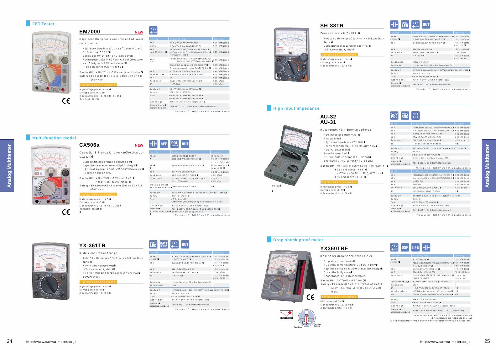
FET Tester
High input impedance
Drop shock proof meter
Multi-function model
AU-32AU-31
The value in( )at DCV and ACV is input resistance.
Measuring rangeAU-31 Accuracy
±3% of full scale±3% of full scale
±3% of full scale±3% of full scale
±3% of arc
ー�
DCVACV
DCA
ACAResistance
dB
±300m(approx. 1MΩ/V)/3/12/60/300/1000V(10MΩ/V)�300m(approx. 1MΩ/V)/3/12/60/300/1000V(10MΩ/V)�±300m/3A
300m/3A
20k/200k/2M/20M/200M�
-9/+11/+23/+37/+51/+62dB
BandwidthBattery
Fuse
Size / Weight
Standard�accessories included
40~10kHz(0.3V : ±5%) 40~1kHz(3V~ : ±4%)�
R03×4
φ5.2×20mm(250V/0.5A)�
H48×W110×D124mm/approx. 290g
Test lead(TL-61), Instruction manual
Measuring rangeAU-32 Accuracy
±3% of full scale±3% of full scale
±3% of full scale±3% of full scale
±3% of arc
ー�
DCVACV
DCA
ACAResistance
dB
±250m(approx. 1MΩ/V)/2.5/10/50/250/500V(10MΩ/V)�250m(approx. 1MΩ/V)/2.5/10/50/250/500V(10MΩ/V)�±250μ/2.5m/25m/250m/2.5A
250μ/2.5m/25m/250m/2.5A
20k/200k/2M/20M/200M�
-10/+10/+22/+36/+50/+56dB
BandwidthBattery
Fuse
Size / Weight
Standard�accessories included
40~10kHz(0.25V : ±5%), 40~600Hz(2.5V~ : ±5%)�
R03×4
φ5.2×20mm(250V/0.3A)�
H48×W110×D124mm/approx. 290g
Test lead(TL-61), Instruction manual
SH-88TREM7000
CX506a
Measuring rangeFunction Accuracy
±2.5% of full scale±2.5% of full scale
±2.5% of full scale
±3% of arc
±3% of full scale�(3V : ±5%)�
±3% of full scale�(3V : ±5%)�
±3% of full scale�(3V : ±5%)�
BandwidthBattery
Fuse
Size / Weight
Standard�accessories included
40~30kHz(less than 30V : ±3%)30~100kHz(less than 30V : ±1dB)�
R6P×2, 6F22×1
φ5.2×20mm(250V/0.5A)�
H150×W100×D36mm/approx. 280g
Test lead(TL-61), Instruction manual
DCV�(NULL)�
ACV
DCAResistancedB
Capacitance
Continuity
120m/3/12/30/120/300/1200V(20kΩ/V)�±6/15/60/150/600V(40kΩ/V)�
3/12/30/120/300/1200V(9kΩ/V)�
50μ/3m/30m/0.3A
3k/30k/300k/3M/30M�
-10~+63dB
1000μ/0.01/0.1/1F
LED : emitting light at 10Ω or less. Open voltage : 3V
The value in ( )at DCV and ACV is input resistance.
YX-361TRMeasuring rangeFunction Accuracy
±2.5% of full scale±2.5% of full scale
±2.5% of full scale±3% of arc
±3% of full scale�(3V : ±5%)�
Bandwidth 40~30kHz(less than 30V : ±3%)30~100kHz(less than 30V : ±1dB)�
Battery R6P×2, 6F22×1Fuse φ5.2×20mm(250V / 0.5A)�
Size / Weight H150×W100×D37mm / approx. 290g
Standard�accessories included
Test lead(TL-61), Instruction manual
DCV�(NULL)�
ACV
DCA
ResistancedB
ContinuityBattery check
0.1/0.5/2.5/10/50/250/1000V(20kΩ/V)�±5/25V(40kΩ/V)�
2.5/10/50/250/1000V(9kΩ/V)�
50μ/2.5m/25m/0.25A
2k/20k/200k/2M/20M�
-10~+62dB
1.5V
LED : emitting light at 10Ω or less. Open voltage : 3V
The value in ( )at DCV and ACV is input resistance.
Measuring rangeFunction Accuracy
±3% of full scale
±7% of full scale
±6% of full scale
±6% of full scale
±4% of full scale
±7% of full scale
±3% of full scale
±3% of arc
±3% of arc
±5% of full scale
±5% of full scale
DCV
±DCV
ACVrms(50 / 60Hz)�
ACVP-P
DCA
DCA(NULL)�
ACA
Resistance
dB
0.3/1.2/3/12/30/120/300/1000V
±0.15/0.6/1.5/6/15/60/150/600V
3V(approx. 2.5MΩ)/12V(approx. 1.1MΩ)�30V(approx. 800kΩ)/120/300V(approx. 800kΩ)/�750V(approx. 10MΩ)�
Square symmetric wave:8.4V(2.5MΩ/V)�Triangular symmetric wave:8.4V(2.5MΩ/V)�
0.12μ/0.3m/3m/30m/300m/6A
±0.06μ/±0.15m/1.5m/15m/150mA
6A
2k/20k/200k/2M/20M/200M�
-10~+51dB
Sine wave:8.4V(approx. 2.5MΩ/V)/ 33V(approx. 1.1MΩ/V)� 84V(approx. 800MΩ/V)/330/840V(approx. 800kΩ/V)�
Bandwidth
Battery
Fuse
Size / Weight
Standard acce-�ssories included
40Hz~1MHz(below 12V range)�
R6P 1.5V×2, 6F22 9V×1
φ5.0×20mm ceramic(250V / 0.5A)�
φ5.0×20mm ceramic(250V / 6.3A)�
H165×W106×D46mm / approx. 375g
Test lead(TL-21), Spare fuse, Instruction manual,
The value in ( )at DCV and ACV is input resistance.
NEW
NEW
YX360TRFMeasuring rangeFunction Accuracy
±3% of full scale±5% of full scale
±4% of full scale
±3% of arc±5% of arc
*1±5% of full scale
*2
±5% of full scale
Battery R6(IEC) or UM-31.5V×2
Fuse φ5.2×20mm(250V / 0.5A)�
Size / Weight H159.5×W129×D41.5mm / approx. 320g
Standard�accessories included
Instruction manual, Test lead(TL-61T), Hand strap
DCV�(NULL)�
ACV
DCA
0.1V(20kΩ / V)�
0.25 / 2.5 / 10 / 50(20kΩ / V) / 250 / 1000V(9kΩ / V)�±5 / 25V(40kΩ / V)�
10 / 50 / 250 / 750V(9kΩ / V)�50μ / 2.5m /25m / 0.25A
Resistance 2k / 20k / 200k / 2MΩ(X1 / X10 / X100 / X1k)�200MΩ(X100k)
Load current(LI)� 0~150m / 15m / 1.5m / 150μ / 1.5μA
Capacitance 10μF
dB -10dB~+22dB(for 10VAC)~+62dB
DC high voltage DC25kV(optional probe "HV-10T" is necessary)�
hFE 1000 at ×10 range(optional probe "HFE-6T" is necessary)�
The value in bracket at DCV and ACV is input resistance.�*1 Not including the resistance of fuse.�
*2 Pointer indication of the maximum move by charged current in the capacitor.
Measuring rangeFunction Accuracy
120m : ±4%±2.5% of full scale
±3% of full scale
±2.5% of full scale±3% of arc
C1/C2±6% of arc
ー�
ー�
ー�
ー�
(Less than 12V �range : ±4%)�
Bandwidth
Battery
Fuse
Size / Weight
Standard�accessories included��
40~30kHz(12V:40Hz~30kHz 30V~ : 40Hz~10kHz)�
R6P×2, 6F22×1
φ5.0×20mm�(250V/0.5A)arc-extingishing material in ceramic tube
H165×W106×D46mm/approx. 370g
Test lead(TL-21), Alligator Clip lead(CL-506)�Instruction manual, Spare fuse
DCV��
ACV��
DCA
Resistance
Capacitance
hFE(DC Current �Amplification Factor)�
120m(4kΩ)/3/12/30/120300(50kΩ/V)/1000V(15kΩ)�
3/12/30/120/300/750V(8kΩ/V)�
30μ/0.3m/3m/30m/0.3A
5k/50k /500k /5M/50M�
C1 : 50p~0.2μF C2 : 0.01μ~20μFC3 : 1~2000μ�
Transistor hFE:0~1000
The value in ( )at DCV and ACV is input resistance.
The value in ( )at DCV and ACV is input resistance.
AU-32�
�
■��■�■��■����
High input impedance(DCV2.5~12MΩ/V), and 0.12μA range(DCA)�Bandwidth 40Hz~1MHz AC sign wave�Rectangular pulse P-P(Peak to Peak)measure-ment(duty cycle 20% and above)�Wide ohm range 0.2Ω~200MΩ�
High sensitivity for measurement of lower capacitance
Bandwidth : 40Hz~1Mhz(12V range and below)�Safety : IEC61010-1(EN61010-1)2001-02 CAT.Ⅲ
600V Max.
Optional accessories
High voltage probe : HV-50�Carrying case : C-CA�Clip adapter : CL-11, TL-8IC, CL-15�Test lead : TL-21M
■�■�■�■�■�■�■�■����
Auto range selection(V, Ω)�Auto polarity�High input impedance 1~10MΩ�Series capacitor input ※AU-31 ACV only �Auto 0Ω adjustment�Inner battery check�DC / AC auto selection ※AU-32 only�5 ranges DC / AC current ※AU-32 only
Auto range, High input impedance
Bandwidth : 40~10kHz (0.25V : ±5%), 40~600Hz � (2.5V and above : ±5%)� : 40~10kHz (0.3V : ±5%), 40~1kHz � (3V and above : ±4%)�
Optional accessories
High voltage probe : HV-50�Carrying case : C-SP�Clip adapter : CL-11, TL-8IC
■��■�■���
Total 35 wide ranges (22ch sw + additional fuc-tions)�Capacitance measurement 1μF~1F�LED for continuity check
Zero center meter(NULL)�
Optional accessories
High voltage probe : HV-10�Carrying case : C-YS�Clip adapter : CL-11, TL-8IC
■��■�■�■�■����
Total 35 wide ranges (24ch sw + additional fuc-tions)�±DCV zero center meter�LED for continuity check�OUTPUT terminal(series capacitor terminal)�Battery check
Wide measurement range
Optional accessories
High voltage probe : HV-10�Carrying case : C-YS�Clip adapter : CL-11, TL-8IC
■�■�■�■�����
Capacitor & Transistor checker(built-in os-cillator)�
Bandwidth : 40Hz~30kHz(3V and 12V), � 40Hz~10kHz(30V range)�Safety : IEC61010-1(EN61010-1)2001-02 CAT.Ⅲ
600V Max.
Optional accessories
High voltage probe : HV-50�Carrying case : C-CA�Clip adapter : CL-11, TL-8IC, CL-15�Test lead : TL-21M��
26ch switch, wide range measurement�Capacitance measurement 50pF~2000μF�High input impedance 50kΩ / V(DC3~300Vrange)�Switchable DC polarity
■�■�■�■�■����
Best seller drop shock proof meter
Bandwidth : 30~100kHz(AC10V)�Safety : IEC61010-1(EN61010-1)2001-02 CAT.Ⅲ
600V Max. / CAT.Ⅱ1000VDC / 750VAC Max.
Optional accessories
hFE probe : HFE-6T�Clip adapter : CL-11, TL-8IC�High voltage probe : HV-10T
Drop shock proof meter�Null(zero center)meter ±5 / ±25 in DCV�High resistance up to 200MΩ with low voltage�Protective body cover�Capacitance, dB, Li measurement
Taut-Band
TensionSpring
DCAACA
24 25http://www.sanwa-meter.co.jp http://www.sanwa-meter.co.jp
An
alo
g M
ult
ites
ter
An
alo
g M
ult
ites
ter

SP21Measuring rangeFunction Accuracy Measuring rangeFunction Accuracy
Measuring rangeFunction Accuracy
Measuring rangeFunction Accuracy
Measuring rangeFunction Accuracy
Measuring rangeFunction Accuracy
Measuring rangeFunction Accuracy
Measuring rangeFunction Accuracy
±3% of full scale±5% of full scale
±3% of full scale
±3% of full scale±3% of full scale
±3%(T-THP)
ー�
ー�ー�ー�
ー�
±3% of full scale
±3% of full scale
3% of arc
Bandwidth
BatteryFuse
Size / Weight
Standard�accessories included
Bandwidth
BatteryFuse
Size / Weight
Standard�accessories included
Bandwidth
BatteryFuse
Size / Weight
Standard�accessories included
Bandwidth
BatteryFuse
Size / Weight
Standard�accessories included
Bandwidth
Battery
Fuse
Size / Weight
Standard�accessories included
Bandwidth
Battery
Fuse
Size / Weight
Standard�accessories included
Bandwidth
BatteryFuse
Size / Weight
Standard�accessories included
Bandwidth
BatteryFuse
Size / Weight
Standard�accessories included
40~100kHz(AC12V)�
R6P×2�
φ6.3×30mm(250V/0.5A)�
H144×W99×D41mm/approx. 270g�
�
DCV�(NULL)�
ACVDCA
ResistanceCapacitance
Continuity
0.3(5kΩ)/3/12/30/120/600V(20kΩ/V)�±6/30V(20kΩ/V)�
12/30/120/300/600V
60μ/30m/0.3A
2k/20k/2M�
500μF
Test lead(TL-21), Instruction manual
Buzzer sounds at less than approx. 10Ω. Open voltage: 3V
The value in ( )at DCV and ACV is input resistance.�*1⦆ Pointer indication of the maximum move by charged current in the capacitor.
CP-7D±3%
±4%±3%±3% arc
±3%
±3%
±3% arc
±3%
±3%
±3% arc
±5%
±5%
±5%
±3% arc
30~100kHz(AC10V) 30~20kHz(AC50V)�
R6P×1φ5.2×20mm(250V/0.5A)�H119×W85×D23mm/approx. 140g
Test lead(TL-84), Instruction manual
40~20kHz(less than 50V)�
R03×1φ5×20mm(250V/0.5A)�H126×W87×D30mm/approx. 185g
Instruction manual
DCV
ACVDCA
ResistanceLoad current(LI)�
Battery checkdB
0.25/2.5/10/50/250/500V(4kΩ/V)�10/50/250/500V(4kΩ/V)�
0.25m/25m/500mA2k/20k/1MΩ�0~74mA/7.4mA/150μA
0.9~1.5V
-20~36dB
The value in( )at DCV and ACV is input resistance.
AP33DCV
ACVBattery checkDCA
Resistance
10/50/250/500V(2kΩ/V)�
50/250/500V(2kΩ/V)�1.5V/9V25m/250mA
5k/500k�
The value in( )at DCV and ACV is input resistance.
SP20
40~100kHz(AC10V)�
R6P×2
φ6.3×30mm(250V/0.5A)�H144×W99×D41mm/approx. 270g
Test lead(TL-61), Instruction manual
DCV
ACVDCA
Resistance
CapacitanceDC high voltage
Temperature
0.25/2.5/5/10/50/100V(20kΩ/V)/500V(9kΩ/V)�
DC25kV(Optional probe "HV-10" is necessary)�-10 ~ +200℃(Optional probe "T-THP" is necessary)�
10/50/250/500V(9kΩ/V)�50μ/2.5m/25m/0.25A
2k/20k/200k/2M�
500μF
The value in ( )at DCV and ACV is input resistance.�*1⦆ Pointer indication of the maximum move by charged current in the capacitor.
SP-18D
30~80kHz(AC 12V) 30~20kHz(AC 30V)�
R6P×2φ5.2×20mm(250V/0.5A)�
H159.5×W129×D41.5mm / approx. 320g
Instruction manual
DCVACV
DCA
ResistanceBattery check
Capacitance
0.3/3/12/30/120/600V(20kΩ/V)�12/30/120/300/600V(9kΩ/V)�60μ/30m/0.3A
2k/20k/200k/200M�
1.5V/1.5V Coin battery
1000μF
The value in ( )at DCV and ACV is input resistance.�*1⦆ Pointer indication of the maximum move by charged current in the capacitor.
40~5kHz
R6P×2φ6.3×30mm(250V/3A)�
H142×W97×D38mm/approx. 300g
Test lead(TL-91), Instruction manual
DCV
ACVDCA
ResistanceContinuity
0.3/3/16/30/60V(20kΩ/V)�
30/120/300V(9kΩ/V)�0.5/3 /30A
2k/20k/200k/2M�
Buzzer sounds at less than approx. 10Ω. Open voltage : 3V
The value in ( )at DCV and ACV is input resistance.
The value in ( ) at DCV and ACV is input resistance.
40~20kHz(less than 50V : 3%)�R6P×2
φ5.2×20mm(250V/0.5A)�Current-limiting fuse(600V/3A)�
Breaking capacity 100kA
H150×W100×D36mm/approx. 280g
Test lead(TL-100F), Carrying case(C-PW), �Instruction manual
DCV
ACVResistance
0.1/1/5/50/250/750V(20kΩ/V)�
6/30/300/600V(9kΩ/V)�5k/500k /5MΩ�
40~5kHz(less than AC50V)�R6P×2
Current-limiting fuse 600V/3A, Breaking capacity 100kAGlass-tube fuse φ6.3×30mm 0.25A/250V, Breaking capacity 100A
H144×W96×D56mm/approx. 400g
Test lead (TL-100-0M), Carrying case(C-VS),�Instruction manual
DCV
ACVResistance
10/50/250/500V(4kΩ/V)�
10/50/250/500V(4kΩ/V)�2k/20k /2MΩ�
The value in( )at DCV and ACV is input resistance.
PW-100Fb(with case)�
VS-100(with case)�
TA55
NEW
Drop shock proof meter
For power line
Slim compact AMT
*1
3% of arc*1
±3% of full scale
±3% of full scale
±4% of full scale±5% of full scale
±3% of full scale±3% of full scale
ー�
3% of arc
3% of arc
*1
■�■�■�■�■����
Drop shock proof taut-band meter�±DCV zero center meter�Fuse and diode protection�Battery check�Tilt stand
Continuity check buzzer
Bandwidth : 40~100kHz(AC12V)�Safety : IEC61010-1(EN61010-1)2001-02 CAT.Ⅲ
600V
Optional accessories
High voltage probe : HV-20�Carrying case : C-SPH or C-SP�Clip adapter : CL-11, TL-8IC, CL-15
■�■�■�■��
20ch measurement ranges�Capacitance measurement 500μF�Tilt stand�DC high voltage and temperature measurement (with optional accessories)�
DC high volotage & temperature measurable
Bandwidth : 40~100kHz(AC10V)��Optional accessories
High voltage probe : HV-10�Temperature probe : T-THP�Carrying case : C-SPH or C-SP�Clip adapter : CL-11, TL-8IC
Optional accessories
Clip adapter : CL-11, TL-8IC
■�■�■��■�■����
Low power ohm(3V)measurement upto 200MΩ�Capacitance measurement 0.01μF~1000μF�LED check by 3V terminal voltage at resistance range�Battery check�Protective body cover
Protective body cover
Bandwidth : 30~80kHz(AC12V), 30~20kHz� (AC30V)�
■�■�■�■����
High level panel visibility�Continuity check buzzer�Tilt-stand�Measureable upto DC30A / DC300A with optinal clamp probe
30A range for automotive
Bandwidth : 40~5kHz
Optional accessories
Clamp probe : CL33DC�Carrying case : C-SPH or C-SP�Clip adapter : CL-11, TL-8IC�Test lead : TL-91M
■��■��■��■����
For lower voltage circuit(500V and below)with large capacitance�Current-limiting fuse that can interrupt 100kA, is installed.�All renges are protected from input voltage upto 500V�Carrying case
Current-limiting fuse, 100kA interrupting rating, is installed.
Bandwidth : 40~5kHz(50V and below)�
■��■�■��■����
For lower voltage circuit(500V and below)with large capacitance�±DCV measurement, Ω polarity switch�Current-limiting fuse that can interrupt 100kA, is installed.�Carrying case
High performance AMT with intensified safety
Bandwidth : 40~20kHz(50V and below : 3%)�
■�■�■�
Elastomer material absorbs shock from fall�High-durability nylon-woven copper lead�Using elastomer material improves flexibility and reduces the stress on the lead wire and the probe when bent.
Small pocket size
Bandwidth : 40~10kHz(50V and below)�Safety : IEC61010 CAT.Ⅲ 300V CAT.Ⅱ 500V
Optional accessories
Clip adapter : CL-15
■�■�■��■�■����
Wide scale panel with mirror�Affixed test leads providing better safety�High-precision, non-flammable, smokeless met-al-oxide film resistor�Battery check�Fuse and diode circuit protection
23mm thick small size
Bandwidth : 30~100kHz(AC10V), � 30~20kHz(AC50V)�
Optional accessoriesCarrying case : C-CP�Clip adapter : CL-11, TL-8IC
Optional
26 27http://www.sanwa-meter.co.jp http://www.sanwa-meter.co.jp
An
alo
g M
ult
ites
ter
An
alo
g M
ult
ites
ter

�
For STH-500C
(Sheathe type / -50.0℃~450℃)
For STH-1200
(Sheathe type / -50.0℃~600℃)
For STH-1200
(Sheathe type / -50.0℃~1200℃)�
Feature
Sanwa Product
Thermistor type Thermocouple Platinum resistance bulb
Earth Testers Thermo MetersWhen some extraordinary cases occur, fault current and overcurrent may cause damages to equipment or a risk to hu-mans because the equipment is not grounded. To prevent such risks, ground-ing plays an important role to assure safety. Grounding provides an escape way to electricity from an electric appli-ance through metal rod driven into the ground. After grounding works are per-formed to prevent hazards and assure safety, the earth resistance is measured. To measure the earth resistance, two grounding rods are stuck into the ground. Assuming that two rods are E and C, AC current I is applied between E and C. The earth resistance can be measured from the voltage generated between E and C. The relation between the current I and voltage V is expressed as follows. From this the earth resistance can be ob-tained. However, the earth resistance R obtained this way includes not only the
earth resistance at the grounding elec-trode E but also the earth resistance at the grounding electrode C. If a third grounding electrode P is provided be-tween the grounding electrodes E and C, the earth resistance RE at the grounding electrode E alone can be obtained from the current I and voltage Vp between E and C.
* Although the grounding electrode P, too, has a resistance zone, it hardly affects the measurement because the im-pedance of the power supply of AC constant current is high.
There are two types of Thermo meters used in general : mercury thermo me-ter and alcohol thermo meter. For in-dustrial use, an electric thermo meter with separate temperature detec-tion element and display element is often used.
Purpose of earth resistance
Three-electrode methodArrange the earth E and auxiliary grounding rods P and C in a straight line at intervals of about 5 to 10m.
* If they cannot be arranged in a straight line because of the pres-ence of an obstacle, arrange E-P and E-C at angles of about 30 degrees or less.
Two-electrode methodIf an earth E whose grounding resistance is known is present nearby, the unknown ground-ing resistance can be measured by using it. Connect the terminal E of the earth resistance meter and the earth E by a cord. Measure-ments are taken between E and P / C assum-ing P and C terminals as one terminal.
* The indicated value includes the known resistance value of the earth E. Subtract the grounding resistance of E to obtain the true value.
△ Sand, gravel and frozen soil → Expose soil.△ Concrete → Use a net. Flush enough water
on the net to let it have a close contact with the ground.
× Asphalt → Cannot be measured.
Arrangement of grounding rods
Temperature measurement method
Measurements are made by using chan-ges in electric resistance(inverse pro-portion). This type is low-priced but not suitable for measurements of high tem-perature(300 degrees or more).
Measurements are made by using tempera-ture difference of contacts when two types of metal wires are electrically connected. It responds quickly, is easy to be processed and operates easily.
It is more accurate than a thermocouple and suitable for low temperature measure-ment. However, it does not respond quick-ly and is not suitable for the measurement of minute spots.
Use T-THP. Use K-8 series. STH500, STH500CT-300PC(for PC5 series and PC20)T-450(for STH-500C)�
1. Measurement of semisolid object 2. Measurement of liquid 3. Measurement of surface temperature
Water tank
Water
℃�
Temperature measuring point
Apple
℃�
Temperature measuring point
Tip of soldering gun
Temperature measuring point
Put the end of the sheath into a semisolid object(apple), and the temperature at the temperature measuring point is indicated.
Put the end of the sheath into liquid(wat-er), and the temperature at the tempera-ture measuring point is indicated.
Let the end of the sheath contact the object to be measured(tip of soldering gun), and the temperature at the temperature measur-ing point is indicated.* Be sure to turn the power off after
measurement is complete.
Current I
Sensor Type
Earth resistance �measuring range
Earth AC voltage �measuring range
Display
OperationBattery
Size / Weight
Standard �accessories included
Standard �accessories included
200/2000Ω Resolution 0.1/1Ω�Accuracy ±(3%+5)�
0~30V Resolution : 0.1VAccuracy±(3%+5)�
LCD Max. 1999 with overrange indication
Constant current system(tripolar or bipolar)�R6P×6
W163×H100×D47mm/470g
Carrying case for PDR-200DG(C-PDR200), Earth bar set (SET-PDR201),Carrying bag for PDR-200DG and accessories(C-PDRCB),Instruction manual
PDR-200DG
Earth resistance �measuring range
Earth resistance �measuring range
10/100/1000Ω�Accuracy : ×1 range ±5% of full scale : ×10, ×100 range ±2.5% of full scale
0~30V
DisplayOperation
Battery
Size / Weight
Accuracy ±2.5% of full scale
AnalogConstant current system(tripolar or bipolar)�
R6P×6W175×H118×D55mm/Approx. 500g
Earth bar set(SET-PDR201),Instruction manual
PDR-301
Measuring range
Resolution
AccuracySampling rateDisplay
Sensor
Response
Battery
Power consumption
Accuracy assure �temperature
Operating �temperature
Storage �temperature
Size / weight
Thermo �sensor Platinic thin film thermoresistor Thermocouple K(CA)
-50.0~199.9℃� -50~450℃�
±(0.5%+0.5℃)�
R6P×4
Approx. 250 hours
W320×H42×D31mm/approx. 210g(STH-500)�W173×H42×D31mm/approx. 200g�(STH-5000C/STH-1200)�
Approx. 50 hours
ー�
±(0.5%+2℃)�
±(0.8%+2℃)�for -20~1200℃ *
±(0.8%+4℃)�for -50~-20℃�
-50~1200℃�Measuring �range
Accuracy
Battery
Cold junction �compensation
Automatic compen-�sation using IC
Continuous �operating hours
Standard �accessories �included
Size / Weight�(excluding �sensor probe)�
Standard �accessories included
-50.0℃~200.0℃�
0.1℃�
±(0.5%+0.5℃)�
SR-44×2
Approx. 18mW
23℃±7℃ max. 80% RH No condensation
0℃~40℃ max. 80% RH No condensation
-10℃~50℃ max. 80% RH No condensation
H117×W76×D18mm/Approx. 120g
Instruction manual
Instruction manual
Approx. 2 times/sec.3999
Platinum foil thermometric resistor(100Ω at 0℃)�
Approx. 7 sec. interval�(speed of sensor's response to achieve the level of 90%)�
Sheath type Pt 100Ω φ2 x 64 JIS B class
STH-500 STH-5000C STH-1200
TH3
STH-500
T-450 K-600 K-1000
STH-500C
STH-1200
* When environmental temperature is 25±4℃
Earth Tester
Thermo Meter
■�■��■�■�■��
Easy to use portable design�AC 30V range to avoid indication errors caused by leak current�Easy self calibration�Power saving design with push switch�Low battery power indication
■��■�■��■�■��
Phase detection system circuit for stable meas-urement�Easy self calibration�AC 30V range to avoid indication errors caused by leak current�Power saving design with push switch�Exorbitance warning LED of auxiliary earth elec-trode resistance
■�■��■�■�■�■��
Easy to carry in a shirt pocket�Sensor prove can be snapped into a fixed posi-tion atop the case�Data hold, Max / Min hold�Relative value�Nonslip sensor holder�Auto power save(30min.)�
■�■�■�■�■��
Easy to use palm design�Sensor-replaceable unit(STH-500C / STH-1200)�Suitable for measurement of liquid and foods�Backlight�Data hold
Direct reading digital earth tester
Analog type display
High accuracy & resolution
Sensor-replaceable�(Optional sensor probe required)��
Direct-coupled sensor �(Platinic thin film thermoresistor)�
Sensor-replaceable(K-type) �(Optional sensor probe required)�
Carrying case : C-STH
Optional accessories
Carrying case : C-PDR300 Optional accessories
Pocket size meter but with high accuracy and wide ranges.�Sensor / Probes can be all neatly contained and protected �within the folding case. Easy to carry in a shirt pocket.
28 29http://www.sanwa-meter.co.jp http://www.sanwa-meter.co.jp
Vari
ous
Inst
rum
ents
Vari
ous
Inst
rum
ents

Various environments need appropriate illumination, whether it be ordinary homes, offices, or factories. Inadequate illumin-ation or too much illumination can lead to false recognition, reduced work efficiency, and loss of vision caused by fatigue. Since appropriate illumination helps to improve work efficien-cy and assure work safety, the control of illumination is re-
garded as a very important element. The illuminance meter indicates, by values in the unit of LUX, how much light shines on each place. It is used for the purpose of assuring appropriate illumination suitable for every environment. JIS(Japanese Industrial Standards)has a standard given below as recommended values for each environment.
Housing�
School�
Office�
Road, park�
Hospital�
�
Inn, hotel�
�
�
Shop
*Studying, Sewing�*Reading(Long time or small �letters)�
*Reading *Makeup �*Eating meal
Living room, child room, �reception room, dining room, kitchen
Hall, stairway, corridor, �escape stairway, �garage
Auditorium, meeting room, hallway, �stairway
Work room, change room, stairway, �warehouse
Tunnel of expressway �(Illumination at the entrance and exit �should be higher than this value.)�
*Ticket counter, doorway, �back stage
Spectators' seat �(during a break), �escape stairway, garden
*Register, kitchen, �*dining table
Ordinary display of shop�Overall shop
Atmospheric display
*Hairdo, *dressing
Ordinary classroom, �special classroom, �library reading room
Executive room, �conference room, �reception room, hall, elevator
Clinic, examination room, �dispensary, waiting room, �medical office
Surgical room, first-aid station, �ocular inspection, drug preparation �*Technological research *Injection
Drafting room *Blackboard�*Sewing *Library reading room�*Precision machining
Accounting office Front desk, dining room
Projection booth, corridor, stairway
Guest room, amusement hall, �corridor, lobby
Guest room, waiting room hallway
In shop
Escape stairway
Escape stairway
70~15�Tunnel
15~3�Road with �busy traffic
Doctor's room, hospital room, �X-ray room, medicine room
*Hairdo *Hair setting *Makeup
*Sample case
Surgical table10,000 over
1.5~0.3�Road with scarce traffic, �road in residential areas, �park, other open spaces
3~1.5�Spectators' seats (while showing)�
LUXType 1500 700 300 150 70 30 15 -LUX-
The combined use of local illumination is allowed in places marked with *. In these cases, it is desirable that the overall illumination should be 1 / 10 or more of the illumination by the local illumination. * Reference: Illumination level JIS 9110
Lux Meters Optical Power Meters
Theater,�movie theater
Diner,�restaurant
Beauty parlor,�barber
Department�store
*Sewing(Dark material)�
*Precision drawing�*Machine-sewing�*Precision experiment��*Designing *Drawing�*Typing *Calculation�*Key-punching
Office, drafting room, gage board, �telephone exchange room, �distribution board
*Autopsy�*First-aid treatment�*Drug formulation
*Highlighted display in �show window�*Highlighted show case
*Highlighted display in shop�*Show window, �ordinary show case
*Show window,�main part on the 1st floor�*Highlighted show case
Ordinary display�Ordinary show case
■830nm Infrared semiconductor laser■780nm Infrared semiconductor laser (e.g. Used for CD player, MD recorder, etc.)■670nm Visible semiconductor laser
■ 633nm He-Ne laser, red semiconductor laser (e.g. Used for DVD player, bar-code reader, etc.)■532nm Green laser■488nm Argon ion laser■405nm Purple-blue laser
Reference: Main laser wavelength
Conversion of dBm into mW 〔dBm〕=10 log 10〔mW〕�
10dBm=10mW 0dBm=1mW -10dBm=100μW -20dBm=10μW �-30dBm=1μW -40dBm=100nW -50dBm=10nW -60dBm=1nW
Wavelength for each modelFor long wave and long wavelength(1310nm,1550nm)For short wave and long wavelength(650nm,780nm,800nm,850nm,880nm)* Please contact us for products handling wavelengths other than the ones given above.
Laser power meters are measuring instruments that let a laser beam emitted from a laser light source enter the sensor light receiver and indicate the value by converting light energy into electric signals. The unit used for this purpose is W(watt). The laser power meter is used for checking the light power of and maintaining laser-operating equipment. Since silicon pho-to diode used at the receiver of the laser power meter has dif-ferent photoelectric conversion ratios according to the wave-length of the light received, it needs to be calibrated by the measuring wavelength.* It is possible to obtain approximate value for the measuring wavelength based on a spectral
sensitivity characteristic graph of the silicon photo diode.
Laser power meters
Optical power meters are measuring instruments that indicate the power of an outgoing beam from an optical fiber connector by converting it into electric signals. It is mainly used for instal-lation and maintenance of optical fiber and optical LAN. The unit of fiber light is generally expressed in W(watt)and dBm related to 1mW expressed in logarithm.
Optical power meters
Display
Optical power measuring range
4-digit digital
Measurable wavelengths
Ranges
Accuracy
Photosensor
Size / Weight
Standard �accessories included
Display
Ranges
Optical sensor
Optical power �measuring range
Optical input type
Reference wavelengths
Accuracy
Resolution
Measuring cycle
Battery
Size / Weight
Standard �accessories included
1310/1550nm(2 ranges)�
-60.00~0.00dBm/1.00nW~1.000mW
Automatic
±5%(@ reference wavelength of -23dBm/5μW)�
InGaAs-Pin photodiode φ1mmBattery Inner rechargeable battery or AC adapter(AD-30)�
H164×W85×D35mm/400g
AC adapter(AD-30), Instruction manual
OPM-360
4-digit digital
Automatic, 8 ranges
Si photodiode(sensor surface area 5.8×5.8mm)�
-60.00dBm~+13.00dBm 1.000nW~20.00mW
Direct to photodiode
650nm, 780nm, 800nm, 850nm, 880nm
±5%(@ reference wavelength of -20dBm/10μW)�
dBm/dB(REL)mode : 0.01dBW/W(REL) mode : 0.01%
3.33 times/sec.
006P type Alkaline battery or AC adapter(AD-30)�
Main body : H164×W85×D35mm/300g�Sensor head : φ25×26mm/25g
Optical sensor, Extension cord, AC adapter(AD-30)�FC-type(F01)connector adapter, Instruction manual
OPM37LAN
Accuracy : 18℃~25℃ max. 80% RH no condensation
※Consult us regarding FC type connector.
Accuracy : 18℃~25℃ max. 80% RH no condensation
Sensor extension cord(2m)�
Optical sensor
Display
Sampling rate
Measuring range
Accuracy
Temperature �Characteristics
Relative �spectral sensitivity
Grazing-incidence �light characteristics
BatteryPower consumption
Operating temperatureStorage temperature
Size / weight
Standard �accessories included
Si photodiode with approximated relative luminous efficiency(φ9mm)�
Numeric : 3999 full scale, Bargragh:42-segment
Approx. 2 times/sec. for numeral display.Approx. 20 times/sec. for bar graph.
400.0/4000/40.00k/400.0klx
±(7%+1) below 3000 lx±(10.5%+1) 3000 lx or higherCompatible JIS standard A class23℃±2℃�
±5% at 23℃ within operating �temperature/humidity range
Approximation of spectral luminous efficiency �of the standard photometric observer
Cosine curve approximation
SR-44 or LR-44×2
Approx. 10mW
0℃~40℃ max. 80% RH no condensation
-10℃~50℃ max. 80% RH no condensation
Main body : H117×W76×D18mm/approx. 120gSensor probe : H84× W16×D10mm
Instruction manual
LX2
Range
Accuracy
Optical sensor
Indicator
Size / Weight
Standard �accessories included
100/300/1000/3000/10000LUX
±10% of full scale Receiver angle 30°(less than -3%)� Receiver angle 60°(less than -10%)�
Si photodiode with approximated relative luminous efficiency
Analog pointer Taut-bandH163×W100×D47mm/300g
Instruction manual
LX3132
Lux Meter
Optical power meter
■��■�■�■�■�■�■����
Small stick shape sensor probe(sensor diame-ter φ9mm)�3999 count with analog bar graph�Silicon photodiode�Measuring range 0.1lx~399.9klx�Data hold�Auto power save(30min.)�Cord length 900mm
Easy to use lux meter
■��■�■��
Various light source can be measured such as fi-lament lamp, fluor lamp, and mercury lamp.�Silicon photodiode�Taut-band drop shock proof meter
Max 10000 lux measurable
■�■�■��■��■�■��■����
dBm and W measurement�Relative value�Offsetting, data averaging(20-data sequential averaging)�Direct reading wavelength(650, 780, 800, 850, 880nm)�RS-232C interface�Various connectors can be equipped by chang-ing optical connector adapter.�2m long sensor extension cord
For fiber light(short wavelength 5 ranges)Optical FC type fiber connector
■�■��■�
Direct reading 2 wavelength ranges(1310/1550nm)�2 types power supply(AC adapter or inner re-chargeable battery)�4 digits digital display(-60.00~0.00dBm/1nW~1mW)�
For fiber light(long wavelength 2 ranges) Optical SC type fiber connector
Optional accessories
Carrying case : C-01
Optional accessories
RS232C cable : KB-RS-OPM�SC-type optical connector adapter : OPA-F04�Simplex TOSLINK type optical connector adapter : OPA-F05�
※Consult us regarding other type of connector.
Vari
ous
Inst
rum
ents
Vari
ous
Inst
rum
ents
Pocket size meter but with high accuracy and wide ranges.�Sensor / Probes can be all neatly contained and protected �within the folding case. Easy to carry in a shirt pocket.
30 31http://www.sanwa-meter.co.jp http://www.sanwa-meter.co.jp
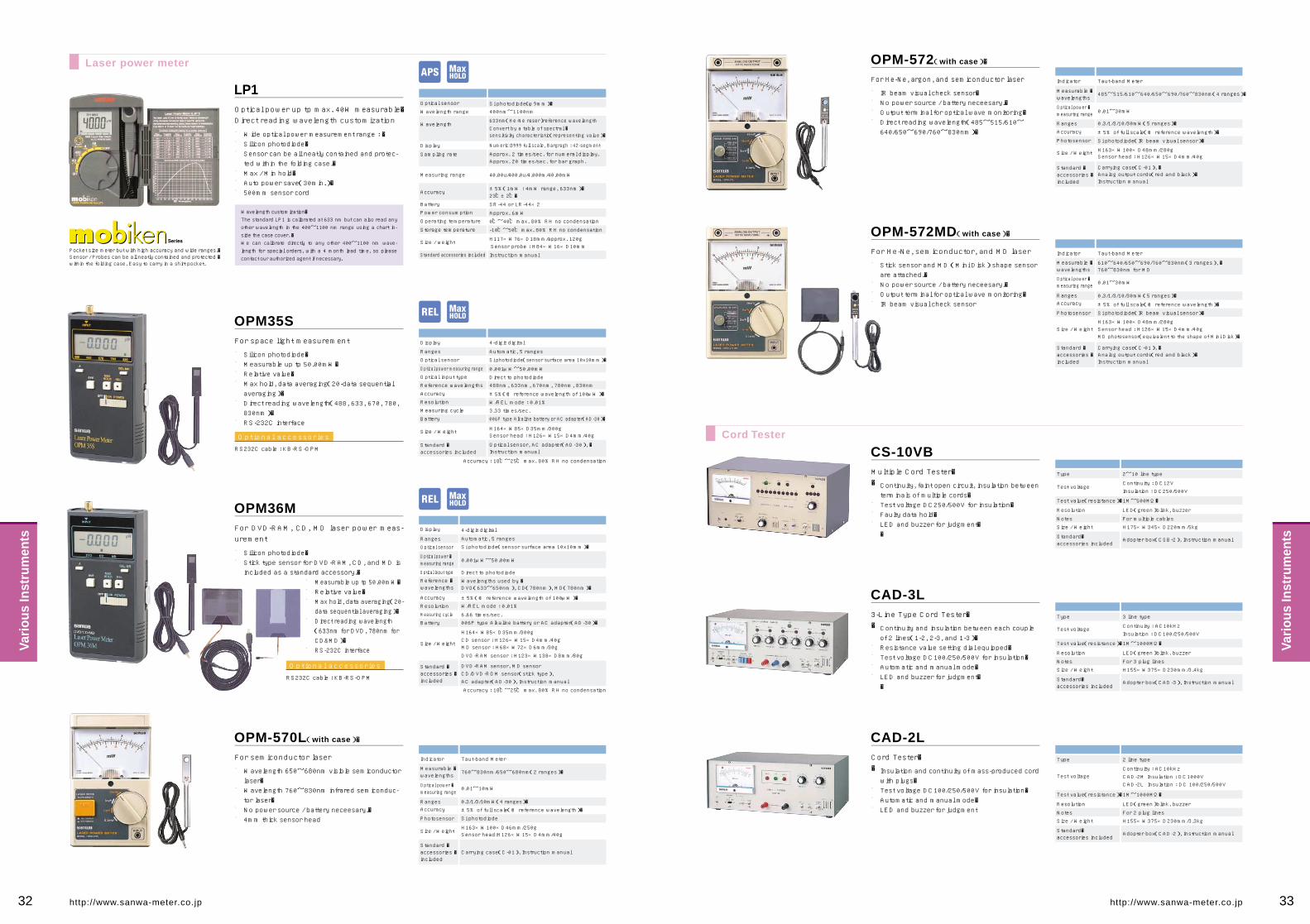
Wavelength customization�The standard LP1 is calibrated at 633 nm but can also read any other wavelength in the 400~1100 nm range using a chart in-side the case cover. �We can calibrate directly to any other 400~1100 nm wave-length for special orders, with a 4 month lead time, so please contact our authorized agent if necessary.
Display
Ranges
Optical sensor
Optical power measuring range
Optical input type
Reference wavelengths
Accuracy
Resolution
Measuring cycle
Battery
Size / Weight
Standard �accessories included
4-digit digital
Automatic, 5 ranges
Si photodiode(sensor surface area 10x10mm)�
0.001μW~50.00mW
Direct to photodiode488nm, 633nm, 670nm, 780nm, 830nm
±5%(@ reference wavelength of 100μW)�
W/REL mode : 0.01%
3.33 times/sec.006P type Alkaline battery or AC adapter(AD-30)�
H164×W85×D35mm/300gSensor head : H126×W15×D4mm/40g
Optical sensor, AC adapter(AD-30), �Instruction manual
OPM35S
Indicator Taut-band Meter
Measurable �wavelengths
Optical power �measuring range
RangesAccuracy
Photosensor
Size / Weight
Standard �accessories �included
760~830nm/650~680nm(2 ranges)�
0.01~10mW
0.3/1/3/10mW(4 ranges)�±5% of full scale(@ reference wavelength)�
Si photodiode
H163×W100×D46mm/250gSensor head:H126×W15×D4mm/40g
Carrying case(C-01), Instruction manual
OPM-570L(with case)�
Accuracy : 18℃~25℃ max. 80% RH no condensation
Display
RangesOptical sensor
Optical input type
Reference �wavelengths
Accuracy
Resolution
Measuring cycle
Battery
Size / Weight
Standard �accessories �included
Optical power �measuring range
4-digit digital
Automatic, 5 rangesSi photodiode(sensor surface area 10x10mm)�
0.001μW~50.00mW
Direct to photodiode
Wavelengths used by �DVD(633~650nm), CD(780nm), MD(780nm)�
±5%(@ reference wavelength of 100μW)�W/REL mode : 0.01%
6.66 times/sec.006P type Alkaline battery or AC adapter(AD-30)�
H164×W85×D35mm/300gCD sensor : H126×W15×D4mm/40gMD sensor : H68×W72×D6mm/30g
DVD-RAM sensor : H123×W138×D8mm/80g
DVD-RAM sensor, MD sensorCD/DVD-ROM sensor(stick type), AC adapter(AD-30), Instruction manual
OPM36M
Accuracy : 18℃~25℃ max. 80% RH no condensation
Test voltageContinuity : DC12V
Test value(resistance)�1M~500M�
Resolution LED(green)blink, buzzer
Notes For multiple cables
Size / Weight H175×W345×D220mm/5kg
Standard�accessories included
Adopter box(CSB-2), Instruction manual
Insulation : DC250/500V
Type 2~10 line type
Test voltageContinuity : AC10kHz
Test value(resistance)�1M~1000M�
Resolution LED(green)blink, buzzer
Notes For 3 plug lines
Size / Weight H155×W375×D230mm/3.4kg
Standard�accessories included
Adopter box(CAD-3), Instruction manual
Insulation : DC100/250/500V
Type 3 line type
Test voltageContinuity : AC10kHz
Test value(resistance)�1M~1000M�
Resolution LED(green)blink, buzzer
Notes For 2 plug lines
Size / Weight H155×W375×D230mm/3.3kg
Standard�accessories included
Adopter box(CAD-2), Instruction manual
CAD-2M Insulation : DC1000VCAD-2L Insulation : DC 100/250/500V
Type 2 line type
CS-10VB
CAD-3L
CAD-2L
LP1Optical sensor
Wavelength range
Wavelength
Display
Sampling rate
Measuring range
Accuracy
Battery
Power consumption
Operating temperature
Storage temperature
Size / weight
Standard accessories included
Si photodiode(φ9mm)�400nm~1100nm
633nm(He-Ne raser)reference wavelengthConvert by a table of spectral �sensitivity characteristic(representing value)�
Numeric:3999 full scale, Bargragh : 42-segment
Approx. 2 times/sec. for numeral display.Approx. 20 times/sec. for bar graph.
40.00u/400.0u/4.000m/40.00mW
±5%(1mW : 4mW range, 633nm)�23℃±2℃�
SR-44 or LR-44×2
Approx. 6mW
0℃~40℃ max. 80% RH no condensation
-10℃~50℃ max. 80% RH no condensation
H117×W76×D18mm/approx. 120gSensor probe : H84×W16×D10mm
Instruction manual
Laser power meter
Cord Tester
Indicator
Measurable �wavelengths
Optical power �measuring range
RangesAccuracy
Photosensor
Size / Weight
Standard �accessories �included
Taut-band Meter
0.01~30mW
0.3/1/3/10/30mW(5 ranges)�
±5% of full scale(@ reference wavelength)�
Si photodiode(IR beam visual sensor)�
H163×W100×D48mm/280gSensor head : H126×W15×D4mm/40g
Carrying case(C-01), �Analog output cords(red and black)�Instruction manual
MD photosensor(equivalent to the shape of Mini Disk)�
610~640/650~690/760~830nm(3 ranges), �760~830nm for MD
OPM-572MD(with case)�
■�■�■�■��■��■����
Silicon photodiode�Measurable up tp 50.00mW�Relative value�Max hold, data averaging(20-data sequential averaging)�Direct reading wavelength(488, 633, 670, 780, 830nm)�RS-232C interface
For space light measurement
■�■����
■�■�■��■���■����
Silicon photodiode�Stick type sensor for DVD-RAM, CD, and MD is included as a standard accessory.�
Measurable up tp 50.00mW�Relative value�Max hold, data averaging(20-data sequential averaging)�Direct reading wavelength(633nm for DVD, 780nm for CD&MD)�RS-232C interface
For DVD-RAM, CD, MD laser power meas-urement
■��■��■�■�����
Wavelength 650~680nm visible semiconductor laser�Wavelength 760~830nm infrared semiconduc-tor laser�No power source / battery neceesary.�4mm thick sensor head
For semiconductor laser
Optional accessories
RS232C cable : KB-RS-OPM
Optional accessories
RS232C cable : KB-RS-OPM
■��■�■�■�����
Continuity, faint open circuit, insulation between terminals of multiple cords�Test voltage DC250/500V for insulation�Faulty data hold�LED and buzzer for judgment��
Multiple Cord Tester��
■��■�■�■�■�����
Continuity and insulation between each couple of 2 lines(1-2, 2-3, and 1-3)�Resistance value setting dial equipped�Test voltage DC100/250/500V for insulation�Automatic and manual mode�LED and buzzer for judgment��
3-Line Type Cord Tester��
■��■�■�■�����
Insulation and continuity of mass-produced cord with plugs�Test voltage DC100/250/500V for insulation�Automatic and manual mode�LED and buzzer for judgment
Cord Tester��
Optical power up tp max. 40W measurable�Direct reading wavelength customization
■�■�■��■�■�■�����
Wide optical power measurement range : �Silicon photodiode�Sensor can be all neatly contained and protec-ted within the folding case.�Max / Min hold�Auto power save(30min.)�500mm sensor cord
For He-Ne, semiconductor, and MD laser
■��■�■�■����
Stick sensor and MD (Mini Disk) shape sensor are attached.�No power source / battery neceesary.�Output terminal for optical wave monitoring�IR beam visual check sensor
Indicator
Measurable �wavelengths
Optical power �measuring range
RangesAccuracy
Photosensor
Size / Weight
Standard �accessories �included
Taut-band Meter
485~515/610~640/650~690/760~830nm(4 ranges)�
0.01~30mW
0.3/1/3/10/30mW(5 ranges)�
±5% of full scale(@ reference wavelength)�
Si photodiode(IR beam visual sensor)�
H163×W100×D48mm/280gSensor head : H126×W15×D4mm/40g
Carrying case(C-01), �Analog output cords(red and black)�Instruction manual
OPM-572(with case)�
■�■�■�■�����
IR beam visual check sensor�No power source / battery neceesary.�Output terminal for optical wave monitoring�Direct reading wavelength(485~515/610~640/650~690/760~830nm)�
For He-Ne, argon, and semiconductor laser
Pocket size meter but with high accuracy and wide ranges.�Sensor / Probes can be all neatly contained and protected �within the folding case. Easy to carry in a shirt pocket.
32 33http://www.sanwa-meter.co.jp http://www.sanwa-meter.co.jp
Vari
ous
Inst
rum
ents
Vari
ous
Inst
rum
ents

Tachometers/Speed Meters Calibrators
Measuring �range
Accuracy
Measuring �method
60~20000rpm
×1 range : ±1dgt, ×10 range : ±2dgt
Contact
DisplayBattery
9999(LED display)�R6P×4
Size 183×42×31mmWeight Approx. 210g
Standard �accessories �included
Contact adaptor(SE-200AD)�Contact rubber tip(SE-210AD)�Hexagonal wrench(SE-220AD)�Instruction manual
1~333rps
�Measuring �range
Accuracy
Measuring methodDisplay
Detection distance
BatterySize
Weight
Standard �accessories �included
60~50000rpm1~833rps
×1 range : ±1dgt, ×10 range : ±2dgtNon contact9999(LED display)�
10~150mm
R6P×4
170×42×31mm
Approx. 170g
Reflective mark 20 sheets, Instruction manual
Measuring �range
Measuring �time
Accuracy
0~1999.9m/min.
0.2 sec.(sampling time)�
±2dgt
Analog �output
DC0~1999.9mV(at 0m/min.~1999.9m/min.)�Analog output accuracy : ±(0.5%±1mV)�
Data hold Ch.1, Ch.2 isolatedOperation by main switch or external hold switch
Auto �power off
Battery
After 3 minutes of no operation except for during measurment
R6P×4(with battery alarm)�
Size / Weight H174×W50×D50MM/Approx. 480g
Standard �accessories �included
Speed ring thickness 10mm(SE-10)×1�
Speed ring thickness 0.9mm(SE-0.9)×1�
Cord for hold input (SE-L-H)×2�
Cord for analog output(SE-L-O)×1�
Hex wrench×1, Carrying case (C-SE)×1�
External encoder (speed ring)×1(SE-9000M only)�
Instruction manual
4-digit Red LED display(2 ch.)(Max 999.9)�
(LED at upper left in the display will blink when the �measured value exceeds 999.9m/min.)�
SE-9000SE-9000M(with external encoder)
SE-200
SE-100
Measuring data can be remotely monitored by SE-9000M.
●Remote control by SE-9000 / SE-9000M
●Remote control by external encoder(SE-9000M only)�
SE-9000
External encoder(speed ring)�
SE-L-H(1.6m)�
1ch 2ch
SE-L-O(4m)�
Insulation �resistance tester M53
Measuring data can be remotely �held by using SE-L-H cable.
Measuring data can be displayed �by using SE-L-O on the LCD of M53.
SE-9000M1.5m
STD5000M(Order production)�
STD-2000(Order production)�Function Measuring range Best accuracy
DCVACV
DCA
ACAResistance1
Resistance2Power supply
Power consumption
Insulation
Size / Weight
Instruction manualStandard �accessories �included
0.2/2/20/200/700(V)�
0.2/2/20/200/700(V)�
0.2m/2m/20m/200m/700m(A)�
0.2m/2m/20m/200m/700m(A)�
0~200k�
190/1.9k/19k/190k/1.9M/19M(Ω)�
AC100V±10%,50Hz,60Hz�
30VA�
Connecting at 1000pF/10MΩ between circuit earth and case(DCV20VUP:0.22μF/10MΩ)�
H192×W483×D499mm/14.5kg
±(0.05%+2)�
±(0.1%+4)�
±(0.05%+2)�
±(0.15%+5)�
±(0.05%+3)�
±(0.05%)�
Measuring range Generation rangeFunction
Function
SE-200
SE-100
DCV
ACV
DCA
ACA
OHM1
OHM2
Memory
Frequency
Maximum load
�
�
�
10mA�
�
�
�
�
�
10mA�
�
�
�
�
13V�
(Open �
circuit voltage)�
�
�
13V�
(Open �
circuit voltage)�
�
�
―�
―�
―�
―�
―�
―�
―�
0~50mV�
0~500mV�
0~5V�
0~50V�
0~500V�
0~1000V�
0~50mV�
0~500mV�
0~5V�
0~50V�
0~500V�
0~1000V�
0~50μA�
0~500μA�
0~5mA�
0~50mA�
0~500mA�
0~2000mA�
0~50μA�
0~500μA�
0~5mA�
0~50mA�
0~500mA�
0~2000mA�
0~500k�
0.1Hz�
1Hz�
10Hz�
100Hz�
1kHz�
0.1V
Resolution
1μV�
10μV�
100μV�
1mV�
10mV�
100mV�
1μV�
10μV�
100μV�
1mV�
10mV�
100mV�
1nA�
10nA�
100nA�
1μA�
10μA�
100μA�
1nA�
10nA�
100nA�
1μA�
10μA�
100μA�
10Ω�
―�
―�
―�
―�
―�
―�
�
Set accuracy
Measuring range Accuracy
±(0.05%+30μV)�
±(0.03%+30μV)�
±(0.03%+200μV)�
±(0.03%+2mV)�
±(0.03%+20mV)�
±(0.05%+0.3V)�
±(0.1%+50μV)�
±(0.06%+100μV)�
±(0.06%+0.4mV)�
±(0.06%+4mV)�
±(0.06%+40mV)�
±(0.1%+0.4V)�
±(0.05%+30nA)�
±(0.05%+30nA)�
±(0.05%+0.2μA)�
±(0.05%+2μA)�
±(0.05%+20μA)�
±(0.1%+300μA)�
±(0.12%+60nA)�
±(0.12%+80nA)�
±(0.1%+0.5μA)�
±(0.1%+5μA)�
±(0.1%+50μA)�
±(0.15%+0.5mA)�
―�
±0.01%�
〃�
〃�
〃�
〃�
±0.5%+0.4V
50mV�
500mV�
5V�
50V�
500V�
1000V�
50mV�
500mV�
5V�
50V�
500V�
1000V�
50μA�
500μA�
5mA�
50mA�
500mA�
2000mA�
50μA�
500μA�
5mA�
50mA�
500mA�
2000mA�
―�
40~99.9Hz�
40~999Hz�
40~9.99kHz�
0~99.9kHz�
0~999kHz�
0~7V
160/260/360/460Ω�
1.6k/2.6k/3.6k/4.6k�16k/26k/36k/46k�
160k/260k/360k/460k�
1,600k/2,600k/3,600k/4,600k�
16M/26M/36M/46M�
6×15(90)�
±(0.05%+0.1Ω)�
±(0.05%)�±(0.05%)�
±(0.05%)�
±(0.05%~0.08%)�
±(0.05%~0.2%)�
50mV adjust digitMax. display
Output adujust
Operating range
Preheating time
Power supply
Power �consumption
Protection
Size / Weight
Standard �accessories �included
4-1/2 digit(except for 700V, 700mA,OHM2)�
50099
LOCAL(surface panel)�
23℃±3℃ below 70%RH
30~60m.
AC100V±10%, 50Hz, 60Hz
30VA
DC/AC20V UP range with over-load protection circuit/reset switch
DC/AC0.2/2V, DC/ACmA with over-load protection circuit
H180×W480×D580mm/25kg
Instruction manual
Tachometer
Speed Meter
■�■�■�■�■��
Ergonomic design & palm size�Easy to use contact type�One push button operation�Auto data hold for 10 sec.�Auto power off
●�●�●�●�●�
Voltage(DC・AC) : 0~1000V(6 ranges)�Current(DC・AC) : 0~2000mA(6 ranges)�Resistance1 : 0~500kΩ(10Ω steps)�Resistance2 : 24 steps fixed resistance value(4 kinds 6 ranges)�Hz : 30Hz~999kHz(5 ranges)�
The STD5000M is a calibrator with soft touch buttons that can generate a desired DC voltage / current, AC voltage / current, resistance, frequency, etc. with a high degree of accuracy and stability.�The STD5000M is with a memory function allowing a broad range of uses for the device.
■�■�■�■�■�■��
Ergonomic design & palm size�Free of measuring error, non contact type�One push button operation�Auto data hold for 10 sec.�Auto power off�LED to check right detection
■��■�■�■�■�■�■�■��
Suitable for elevator speed measurement of high building�2 independent display�Analog output terminal to record measuring data�2 external hold terminals for remote control�Remote control by external encoder�Easy to read LED display�Auto power off�Low battery power alarm
Contact type digital tachometer
Non contact type digital tachometer
For elevator maintenance, 2ch display
Optional accessories
Carrying case : C-SE2�Tangential speed ring : SE-10(circumference 10cm, width 10mm), � SE-0.9(circumference 10cm, width 0.9mm)
Optional accessories
Carrying case : C-SE2�Reflective mark : 20marks x 5sheets(total 100marks)�
Overview
Ranges
■�■�Desired value setting is possible by choosing a number for each digit.�Five ranges can be switched respectively for each function of DC cur-rent, DC voltage, AC voltage, and AC current. The resistance is com-prised of two types of terminals: a common terminal for 0-200kΩ and 10Ω step, and a terminal dedicated for switching of 6 ranges between 190Ω and 19MΩ.
Overview
■����■�
Use of electronic soft-touch push button switches except the power switch. Speedy value setting and operation are possible. The relay of the low ther-mal electromotive force type and semiconductor switch are used for circuit switches to enhance heat resistance and durability.�Overload protection in case of low voltage and current is performed on the semiconductor circuit, and overload protection in case of medium and high voltage is achieved by releasing the output terminal and output voltage cir-cuit to assure safety. When overload current runs in the voltage range of 20V or more, the LED for DC and AC resetting lights up to give warning.
■�����■�����■���■�����■��
High accuracy ±0.03%(DCV DC mA)�Reliable accuracy is achieved by using the standard voltage IC with a constant-temperature bath for the reference voltage and wire wound re-sistor and metal film resistor with high tolerance and low temperature coefficient for the resistance element.�Calibrates 6 types of functions�With the calibration elements of 6 functions(DCV, ACV, DCA, ACA, OHM, Hz)incorporated, it can be used for calibrating and maintaining the DMM, DPM(digital power meter), circuit tester and industrial instru-ments.�Installs 90 (6x15) output memories�With 90(6x15)output memories installed, it is possible to save desired setting.�User-friendly speedy operability�Use of soft-touch push button switches for operation on the panel(exc-ept the power switch). Use of semiconductor switches with greater heat resistance and durability for change switches of the circuit, and latch-type relays requiring less electro motive force.�With overload protection device�To enhance security, overload protection in case of low voltage and current generation is performed on the semiconductor circuit, and over-load protection in case of medium and high voltage generation(50V or more)is achieved by releasing the output terminal and circuit.
Features
34 35http://www.sanwa-meter.co.jp http://www.sanwa-meter.co.jp
Vari
ous
Inst
rum
ents
Vari
ous
Inst
rum
ents

Accessory mapping Accessory mapping
PC5000
PC520M
PC510
PC500
PC20
RD700
RD701
CD751
CD731
CD721
CD721NH
CD750P
CD800a
DA-50C
DA32
PM10
PM3
PM7a
PS8a
DCL10
DCM60L
DCM400
CAM600S
DCM400AD
DCM-22AD
DCM2000AD
DCL20R
DCL30DR
DLC-400A
DLC-330L
DG6
DG7
DG8
DG9
DG525
DG251
M53
DM1528S
DM5218S
DM1008S
DM508S
PDM508S
DM-1527
DM-5257
EM7000
CX506a
YX-361TR
SH-88TR
AU-32
AU-31
YX360TRF
SP21
SP20
SP-18D
TA55
CP-7D
AP33
PW100Fb
VS-100
TL-21
-
-
-
-
○
-
-
○
○
○
○�
-
-
-
-
-
-
-
-
-
-
-
○�
-
-
○�
-
-
-
-
-
-
-
-
-
-
-
-
-
-
-
-
-
-�
○�
○�
-
-
-
-
-�
○
-
-
-
-
-
-
-
TL-21M
●
●
●
●
●
●
●
●
●
●
●
-
-
-
-
-
-
-
-
-
-
-
●
-
-
●
-
-
-
-
-
-
-
-
-
-
-
-
-
-
-
-
-
-
●
●
-
-
-
-
-
●
-
-
-
-
-
-
-
TL-61
-
-
-
-
-
-
-
-
-
-
-
-
-
○
○
-
-
-
-
-
-
-
-
-
○
-
-
-
○
-
-
-
-
-
-
-
-
-
-
-
-
-
-
-
-
-
○
○
○
○
TL-61T
-
○
-
-
-
-
-
-
TL-82
○
○
○
○
-
○
○
-
-
-
-
-
-
-
-
-
-
-
-
-
-
-
-
-
-
-
-
-
-
-
-
-
-
-
-
-
-
-
-
-
-
-
-
-
-
-
-
-
-
-
-
-
-
-
-
-
-
-
-
TL-84
-
-
-
-
-
-
-
-
-
-
-
-
-
-
-
-
-
-
-
-
-
-
-
-
-
-
-
-
-
-
-
-
-
-
-
-
-
-
-
-
-
-
-
-
-
-
-
-
-
-
-
-
-
-
-
○
-
-
-
TL-88
-
-
-
-
-
-
-
-
-
-
-
-
-
-
-
-
-
-
-
-�
○�
○�
-
○
-
-
-
-
-
-
-
-
-
-
-
-
-
-
-
-
-
-
-
-
-
-
-
-
-
-
-
-
-
-
-
-
-
-
-
TL-91
-
-
-
-
-
-
-
-
-
-
-
-
-
-
-
-
-
-
-
-
-
-
-
-
-
-
-
-
-
-
-
-
-
-
-
-
-
-
-
-
-
-
-
-
-
-
-
-
○�
○�
-
-
-�
-
○
-
-
-
-
TL-91M
-
-
-
-
-
-
-
-
-
-
-
-
-
●
●
-
-
-
-
-
-
-
-
-
-
-
-
-
-
-
-
-
-
-
-
-
-
-
-
-
-
-
-
-
-
-
-
-
●�
●
-
-
●�
-
●�
-
-
-
-
TL-95
-
-
-
-
-
-
-
-
-
-
-
-
-
-
-
-
-
-
-
-
-
-
-
-
-
-
-
-
-
-
-
-
-
-
-
-
-
-
-
-
-
-
-
-
-
-
-
-
-
-
-
-
-
-
-
-
-
-
-
TL-122
-
-
-
-
-
-
-
-
-
-
-
●
-
-
-
-
-
-
-
-
-
-
-
-
-
-
-
-
-
-
-
-
-
-
-
-
-
-
-
-
-
-
-
-
-
-
-
-
-
-
-
-
-
-
-
-
-
-
-
TL-507
-
-
-
-
-
-
-
-
-
-
-
-
-
-
-
-
-
-
-
-
-
-
-
-
-
-
-
-
-
-
-
-
-
-
-
-
-
-
-
-
-
-
○
○
-
-
-
-
-
-
-
-
-
-
-
-
-
-
-
TL-508S
-
-
-
-
-
-
-
-
-
-
-
-
-
-
-
-
-
-
-
-
-
-
-
-
-
-
-
-
-
-
-
-
-
-
-
-
-
○
○
○
○
○
-
-
-
-
-
-
-
-
-
-
-
-
-
-
-
-
-
TL-M54
-
-
-
-
-
-
-
-
-
-
-
-
-
-
-
-
-
-
-
-
-
-
-
-
-
-
-
-
-
-
-
-
-
-
○
○
○
-
-
-
-
-
-
-
-
-
-
-
-
-
-
-
-
-
-
-
-
-
-
TL-100-OM
-
-
-
-
-
-
-
-
-
-
-
-
-
-
-
-
-
-
-
-
-
-
-
-
-
-
-
-
-
-
-
-
-
-
-
-
-
-
-
-
-
-
-
-
-
-
-
-
-
-
-
-
-
-
-
-
-
-
○
CL-11
△
△
△
△
△
△
△
●
●
●
●
-�
●
●
●
-
-
●
●
-�
●
●
●
●
●
●
-
-
●
-
-
-
-
-
-
-
-
-
-
-
-
-
-
-
●
●
●
●
●
●
●
●
●
●�
●
●
-
-
-
CL-13
○
○
●
●
●
●
●
-
-
-
-
-
-
-
-
●
●�
-
-
-
-
-
-
-
-
-
-�
-�
-�
-�
●�
●
●
●
-
-
-
-
-
-
-
-
-
-
-
-
-
-
-
-
-
-
-
-
-
-
-
-
-
CL-15
△
△
△
△
△
△
△
-
-
-
-
-
-
●
●
-
-
-
-
-
-
-
●
-
-
●
-�
-�
-�
-�
○
○
○
○
-
-
-
-
-
-
-
-
-
-�
●
●
-
-
-
-
-
-
-
�
-
-
●
-
-
TL-8IC
△
△
△
△
△
△
△
●
●
●
●
-�
●
●
●
-
-
●�
●�
-�
●
●
●
●
●
●
-
-
●
-
-
-
-
-
-
-
-
-
-
-
-
-
-
-
●�
●
●
●
●
●
●
●
●
●�
●
●
-
-
-
CL-506
-
-
-
-
-
-
-
-
-
-
-
-
-
-
-
-
-
-
-
-
-
-
-
-
-
-
-
-
-
-
-
-
-
-
-
-
-
-
-
-
-
-
-
-
-
○
-
-
-
-
-
-
-
-
-
-
-
-
-
TEST LEADModel CLIP ADAPTER
Model
Digital Multimeter
Clamp Meter
Insulation Resistance Tester
Analog Multitester
● Optional ○ Standard △ Only with TL-21/TL-21M ● Optional ○ Standard △ Only with TL-21/TL-21M
Model
Digital Multimeter
Clamp Meter
Insulation Resistance Tester
Analog Multitester
-
-
-
-
-
-
-
HV-60
HV-60
HV-60
HV-60
HV-60
-
-
-
-
-
-
-
-
-
-
-
-
-
-
-
-
-
-
-
-
-
-
-
-
-
-
-
-
-
-
-
-
HV-50
HV-50
HV-10
HV-10
HV-50
HV-50
HV-10T
HV-20
HV-10
-
-
-
-
-
-
PC5000
PC520M
PC510
PC500
PC20
RD700
RD701
CD751
CD731
CD721
CD721NH
CD750P
CD800a
DA-50C
DA32
PM10
PM3
PM7a
PS8a
DCL10
DCM60L
DCM400
CAM600S
DCM400AD
DCM-22AD
DCM2000AD
DCL20R
DCL30DR
DLC-400A
DLC-330L
DG6
DG7
DG8
DG9
DG525
DG251
M53
DM1528S
DM5218S
DM1008S
DM508S
PDM508S
DM-1527
DM-5257
EM7000
CX506a
YX-361TR
SH-88TR
AU-32
AU-31
YX360TRF
SP21
SP20
SP-18D
TA55
CP-7D
AP33
PW100Fb
VS-100
CL-140
●
●
●
●
●
●
●
●
●
●
●
-
-
-
-
-
-
-
-
-
-
-
-
-
-
-
-
-
-
-
-
-
-
-
-
-
-
-
-
-
-
-
-
-
-
-
-
-
-
-
-
-
-
-
-
-
-
-
-
CL-124
●
●
●
●
●
●
●
●
●
●
●
-
-
-
-
-
-
-
-
-
-
-
-
-
-
-
-
-
-
-
-
-
-
-
-
-
-
-
-
-
-
-
-
-
-
-
-
-
-
-
-
-
-
-
-
-
-
-
-
CL33DC
●
●
●
●
-
●
●
●
●
●
●
●
-
●
●
-
-
-
-
-
-
-
-
-
-
-
-
-
-
-
-
-
-
-
-
-
-
-
-
-
-
-
-
-
-
-
-
-
-
-
-
-
-
-�
●
-
-
-
-
KB-LAN
-
-
-
-
●�
-
-
-
-
-
-
-
-
-
-
-
-
-
-
-
-
-
-
-
-
-
-
-
-
-
-
-
-
-
-
-
-
-
-
-
-
-
-
-
-
-
-
-
-
-
-
-
-
-
-
-
-
-
-
T-THP
-
-
-
-
-
-
-
-
-
-
-
-
-
-
-
-
-
-
-
-
-
-
●
-
-
-
-
-
-
-
-
-
-
-
-
-
-
-
-
-
-
-
-
-
-
-
-
-
-
-
-
-
●
-
-
-
-
-
-
T-300PC
●
●
●
●
●
-
-
-
-
-
-
-
-
-
-
-
-
-
-
-
-
-
-
-
-
-
-
-
-
-
-
-
-
-
-
-
-
-
-
-
-
-
-
-
-
-
-
-
-
-
-
-
-
-
-
-
-
-
-
K-250PC
-
○
○
-
-
○
○
-
-
-
-
-
-
-
-
-
-
-
-
-
-
-
-
-
-
-
-
-
-
-
-
-
-
-
-
-
-
-
-
-
-
-
-
-
-
-
-
-
-
-
-
-
-
-
-
-
-
-
-
K-8-250
-
●
●
-
-
●
●
-
-
-
-
-
-
-
-
-
-
-
-
-
-
-
-
-
-
-
-
-
-
-
-
-
-
-
-
-
-
-
-
-
-
-
-
-
-
-
-
-
-
-
-
-
-
-
-
-
-
-
-
K-8-300
-
●
●
-
-
●
●
-
-
-
-
-
-
-
-
-
-
-
-
-
-
-
-
-
-
-
-
-
-
-
-
-
-
-
-
-
-
-
-
-
-
-
-
-
-
-
-
-
-
-
-
-
-
-
-
-
-
-
-
K-8-500
-
●
●
-
-
●
●
-
-
-
-
-
-
-
-
-
-
-
-
-
-
-
-
-
-
-
-
-
-
-
-
-
-
-
-
-
-
-
-
-
-
-
-
-
-
-
-
-
-
-
-
-
-
-
-
-
-
-
-
K-8-650
-
●
●
-
-
●
●
-
-
-
-
-
-
-
-
-
-
-
-
-
-
-
-
-
-
-
-
-
-
-
-
-
-
-
-
-
-
-
-
-
-
-
-
-
-
-
-
-
-
-
-
-
-
-
-
-
-
-
-
K-8-800
-
●
●
-
-
●
●
-
-
-
-
-
-
-
-
-
-
-
-
-
-
-
-
-
-
-
-
-
-
-
-
-
-
-
-
-
-
-
-
-
-
-
-
-
-
-
-
-
-
-
-
-
-
-
-
-
-
-
-
CL-22AD
●
●
●
●
-
●
●
●
●
●
●
●
-
●
●
-
-
-
-
-
-
-
-
-
-
-
-
-
-
-
-
-
-
-
-
-
-
-
-
-
-
-
-
-
-
-
-
-
-
-
-
-
-
-�
●
-
-
-
-
CL-20D
●
●
●
●
-
●
●
●
●
●
●
●
-
●
●
-
-
-
-
-
-
-
-
-
-
-
-
-
-
-
-
-
-
-
-
-
-
-
-
-
-
-
-
-
-
-
-
-
-
-
-
-
-
-
-
-
-
-
-
KB-USB1
-
-
-
-
●�
-
-
-
-
-
-
-
-
-
-
-
-
-
-
-
-
-
-
-
-
-
-
-
-
-
-
-
-
-
-
-
-
-
-
-
-
-
-
-
-
-
-
-
-
-
-
-
-
-
-
-
-
-
-
KB-USB2
●
●
●
●�
-
-
-
-
-
-
-
-
-
-
-
-
-
-
-
-
-
-
-
-
-
-
-
-
-
-
-
-
-
-
-
-
-
-
-
-
-
-
-
-
-
-
-
-
-
-
-
-
-
-
-
-
-
-
-
KB-RS1
-
-
-
-
●�
-
-
-
-
-
-
-
-
-
-
-
-
-
-
-
-
-
-
-
-
-
-
-
-
-
-
-
-
-
-
-
-
-
-
-
-
-
-
-
-
-
-
-
-
-
-
-
-
-
-
-
-
-
-
KB-RS2
●
●
●
●�
-
-
-
-
-
-
-
-
-
-
-
-
-
-
-
-
-
-
-
-
-
-
-
-
-
-
-
-
-
-
-
-
-
-
-
-
-
-
-
-
-
-
-
-
-
-
-
-
-
-
-
-
-
-
-
CLAMP SENSORModel OPTICAL LINK TEMPERATURE SENSORHIGH VOLTAGEPROBE
36 37http://www.sanwa-meter.co.jp http://www.sanwa-meter.co.jp
Acc
esso
ries
Acc
esso
ries

�
Acc
esso
ries
Acc
esso
ries
Clip adapter
Clip lead for hFE measurement
Length 0.3m
Alligator clip �(use with test leads by inserting pins into socket)�(small size)�Length 0.2m
Alligator clip �(use with test leads by inserting pins into socket)�(big size)�Length 0.2m
IC clip�(use with test leads by inserting pins into socket)�Length 0.2m
Alligator clip �(use with test leads by inserting pins into socket)�IEC1010 CAT.Ⅲ 1000V�Length 70mm
PC Link Plus / PC Link PC Communication Set
CD-ROM
AC adapter
Length 1.9m
Optical link
Optical link RS-232C�PC connection cable �Length 1.9m
Optical link RS-232C�PC connection cable �Length 1.9m
Optical link USB�PC connection cable �Length 1.5m
Optical link USB�PC connection cable �Length 1.3m
Optical link LAN adapter�AC adapter for this item included�Length 1.3m
Test lead
Insert the test pin
Alligator clip
KB-LAN
CL-506
CL-11
TL-8ICHow to use : �CL-11, CL-13, CL-15, TL-8IC
CL-13 CL-15
PC Link PlusPC Link
A : KB-RS1 + PC Link
B : KB-RS2 + PC Link
C : KB-USB1 + PC Link
D : KB-USB2 + PC Link
AD-72AC(220V)�AD-71AC(100V)�
KB-RS2
KB-USB1
KB-USB2 KB-RS1
38 39http://www.sanwa-meter.co.jp http://www.sanwa-meter.co.jp
Test lead
HV probe
IEC1010 CAT.Ⅲ 600V�CAT.Ⅱ1000V�Length 1m�Clip adapter�CL-11�TL-8IC�CL-15
IEC1010 CAT.Ⅲ 1000V�Length 1m�Clip adapter�CL-13
Length 1m
Length 1m
Length 1m Length 1m
φ0.7mm shape-memory�alloy test pin�Exchangeable φ2mm pin�Length 1m�Clip adapter�CL-11�TL-8IC�CL-15
IEC1010 CAT.Ⅲ 600V�CAT.Ⅱ1000V�Length 1.1m�Clip adapter�CL-11�TL-8IC
Length 0.9m�Clip adapter�CL-11�TL-8IC
TL-61 and TL-91 are�compatible�φ0.7mm shape-memory�alloy test pin�Exchangeable φ2mm pin�Length 1m�Clip adapter�CL-11�TL-8IC
Length 0.9m�Clip adapter�CL-11�TL-8IC
Length 1m�Clip adapter�CL-11�TL-8IC
φ4mm pin at body side �Length 1m�Clip adapter�CL-11�TL-8IC
HV-20480MΩresistor�Measurement for�0~30kV or 25kV �Length 1m
HV-601000MΩresistor�Measurement for�0~30kV or 25kV �Length 1.2m
TL-91M
TL-88
TL-M54
TL-21M
TL-82 TL-84
TL-100-OM
TL-91
TL-61
TL-508STL-507
TL-21
TL-95
HV-10 HV-50

Picture not available
Acc
esso
ries
To use K8 series, �K-AD adapter is required.
Temperature sensor
-20℃~200℃�Thermistor probe �Sensor : φ2.5 × 31mm�Length 0.9m
-50℃~300℃�Platinic thin film �Sensor : φ3.2 × 135mm�Length 2.2m�Accuracy : ± 1.9℃�
-50℃~250℃�Linear thermocouple K type�Length 1m
-50℃~250℃�Surface shape thermocouple K type�Sensor : 15 × 16mm�Length 1m
-50℃~300℃�Sheath shape thermocouple K type�Sensor : φ3.1 × 150mm�Length 1.2m
-50℃~650℃�flexible thermocouple K type �Sensor : φ1 × 300mm�Length 1.4m
-50℃~450℃�Platinic thin film �Sensor : φ3.2 × 135mm�Length 1.7m
-50℃~600℃�Sheath shape thermocouple K type�Sensor : φ1.6 × 150mm�Length 2.3m
-50℃~1200℃�Sheath shape thermocouple K type�Sensor : φ4.8 × 500mm�Length 2.6m
Thermocouple K type adaptor for connecting to�K-8-250~K-8-800�Length 50mm
-50℃~800℃�Sheath shape thermocouple K type�Sensor : φ3.1 × 150mm�Length 1.2m
-50℃~500℃�Surface shape thermocouple K type�Sensor : 15 × 16mm�Length 1m
Carrying case
Holster
180 × 150 × 50mm
175 × 110 × 45mm 130 × 120 × 30mm 160 × 125 × 45mm
160 × 150 × 55mm
240 × 155 × 65mm 180 × 140 × 60mm
160 × 140 × 40mm
165 × 140 × 50mm�Soft case
190 × 90 × 45mm�Soft case
190× 145 × 70mm
Acc
esso
ries
ALARM
400mA MAX FUSED
(CAT.III)(CAT.II)
K-AD(optional)�
K type temperature probe�with international�
miniature connector
K-600 K-1000
K-8-800K-8-650
Notice :RD700 / 701 can only measure�-20℃~300℃(max)regardless of the�specification of temperature probe. �Accuracy of K-8-XXX�-40℃~330℃ : ±2.5℃�330℃~1200℃ : ±0.75% of measured� temperature
K-AD
T-THP T-300PC K-250PC
K-8-300 K-8-500K-8-250
T-450
C-CL
C-CA C-C7C-SP
C-YS
C-CD
H-50H-70
C-SPH
C-PC10 / S C-NH7
C-DAC-CPC-CDS
40 41http://www.sanwa-meter.co.jp http://www.sanwa-meter.co.jp

Model
Digit
Category
CE
Range
DCV(V)
ACV(V)
DCA(A)
ACA(A)
Resistance(Ω)
Capacitance(F)
Temperature( c゚)min
Temperature( c゚)max
Frequency(Hz)min
Frequency(Hz)max
Logic frequency(Hz)min
Logic frequency(Hz)max
Continuity
Diode test
Duty cycle
dBm
Auto power off
Auto power save
Battery check
Data hold
Range hold
Peak hold
Relative value
4-20mA%
True RMS(AC+DC)
True RMS(AC)
Auto zero adjust
Bar graph
Max/Min
PC link
Optional AC adapter connection
Dimension(H)mm
Dimension(W)mm
Dimension(D)mm
Weight(g)�
Digital Multimeter comparative chartModel
Digit
Category
CE
Range
DCV(V)
ACV(V)
DCA(A)
ACA(A)
Resistance(Ω)
Capacitance(F)
Temperature( c゚)min
Temperature( c゚)max
Frequency(Hz)min
Frequency(Hz)max
Logic frequency(Hz)min
Logic frequency(Hz)max
Continuity
Diode test
Duty cycle
dBm
Auto power off
Auto power save
Battery check
Data hold
Range hold
Peak hold
Relative value
4-20mA%
True RMS(AC+DC)
True RMS(AC)
Auto zero adjust
Bar graph
Max/Min
PC link
Optional AC adapter connection
Dimension(H)mm
Dimension(W)mm
Dimension(D)mm
Weight(g)�
PC5000
50000/500000
CAT. Ⅲ600V
●
A/M
500m5
50500
1000-
500m5
50500
1000-
500μ
5000μ
50m
500m
5
10
500μ
5000μ
50m
500m
5
10
500
5k
50k
500k
5M
50M
-
50n
500n
5μ
50μ
500μ
9999μ
○
○�
5
200k
5
2M
BUZZER
●
●
●
●�
-
-
●
●
●
●
●
●
●
-
●
●
○
-
179
87
55
460
PC520M
5000
CAT. Ⅲ600V
●
A/M
50m500m
550
500100050m
500m5
50500
1000
500μ
5000μ
50m
500m
5
10
500μ
5000μ
50m
500m
5
10
50
500
5k
50k
500k
5M
50M
50n
500n
5μ
50μ
500μ
9999μ
-50
1000
5
125k
-
-
BUZZER
●
-
-
●�
-
-
●
●
-
-
-
-
●
●
●
-
○
-
179
87
55
460
PC510
5000
CAT. Ⅲ600V
●
A/M
50m500m
550
500100050m
500m5
50500
1000
500μ
5000μ
50m
500m
5
10
500μ
5000μ
50m
500m
5
10
50
500
5k
50k
500k
5M
50M
50n
500n
5μ
50μ
500μ
9999μ
-50
1000
5
125k
-
-
BUZZER
●
-
-
●�
-
-
●
●
●
●
-
-
●
●
ZOOM
●
○
-
179
87
55
460
PC500
5000
CAT. Ⅲ600V
●
A/M
50m500m
550
500100050m
500m5
50500
1000
500μ
5000μ
50m
500m
5
10
500μ
5000μ
50m
500m
5
10
50
500
5k
50k
500k
5M
50M
50n
500n
5μ
50μ
500μ
9999μ
○
○
5
125k
-
-
BUZZER
●
-
-
●�
-
-
●
●
-
-
-
-
-
●
●
-
○
-
179
87
55
460
PC20
4000
CAT. Ⅲ600V
●
A/M
400m4
40400
1000-4
40400750
--
400μ
4000μ
40m
400m
4
10
400μ
4000μ
40m
400m
4
10
400
4k
40k
400k
4M
40M
-
40n
400n
4μ
40μ
100μ
-
○
○
-
-
-
-
BUZZER
●
-
-
-
-
-
●
●
-
-
-
-
-
-
-
-
○
○
167
90
48
330
RD700 / 701
4000
CAT. Ⅲ600V
●
A/M
400m4
40400
1000-
400m4
40400
1000-
400μ
4000μ
40m
400m
4
10
400μ
4000μ
40m
400m
4
10
400
4k
40k
400k
4M
40M
-
500n
5μ
50μ
500μ
3000μ
-
-20
300
50
1M
-
-
BUZZER
●
-
-
●
-
-
●
●
-
●
-
-
RD701 Only
-
-
-
-
-
179
87
55
460
Digital Multimeter comparative chartCD751
3200
CAT. Ⅲ600V
●
A/M
320m
3.2
32
320
1000
3.2
32
320
750
-
32μ
320μ
3200μ
32m
320m
20
32μ
320μ
3200μ
32m
320m
20
320
3.2k
32k
320k
3.2M
30M
-
-
-
-
-
-
-
-
-
-
-
-
-
BUZZER
●
-
-
-
●
-
●
●
-
-
-
●
-
-
●
-
-
-
165.5
78
41.5
315
CD731
3200
CAT. Ⅲ600V
●
A/M
320m
3.2
32
320
1000
3.2
32
320
750
-
32μ
320μ
3200μ
32m
320m
20
32μ
320μ
3200μ
32m
320m
20
320
3.2k
32k
320k
3.2M
30M
-
-
-
-
-
-
-
-
-
-
-
-
-
BUZZER
●
-
-
●
-
-
●
●
-
-
-
-
-
-
●
-
-
-
165.5
78
41.5
315
CD721
3200
CAT. Ⅲ600V
●
A/M
320m
3.2
32
320
1000
3.2
32
320
750
-
32m
320m
12
-
-
-
32m
320m
12
-
-
-
320
3.2k
32k
320k
3.2M
30M
-
-
-
-
-
-
-
-
-
-
-
-
-
BUZZER
●
-
-
●
-
1.5V
●
●
-
-
-
-
-
-
●
-
-
-
165.5
78
41.5
315
CD750P
4000
CAT.III 600V
●
A
400m
4
40
400
1000
4
40
400
750
-
-
-
-
-
-
-
-
-
-
-
-
-
400
4k
40k
4M
40M
-
-
-
-
-
-
-
-
-
-
-
-
-
-
BUZZER
●
-
-
-
●
-
●
●
-
-
-
-
●
-
-
-
-
-
157.5
70
38.5
220
CD800a
4000
CAT. Ⅲ600V
●
A/M
400m
4
40
400
600
4
40
400
600
-
40m
400m
-
-
-
-
40m
400m
-
-
-
-
400
4k
40k
400k
4M
40M
-
50n
500n
5μ
50μ
100μ
-
-
-
5
100k
-
-
BUZZER
●
●
-
●
-
-
●
●
-
●
-
-
-
-
-
-
-
-
176
104
46
340
DA-50C
4000
-
-
A/M
400m
4
40
400
600
400m
4
40
400
600
40m
10
-
-
-
-
40m
10
-
-
-
-
400
4k
40k
400k
4000k
40M
-
-
-
-
-
-
-
-
-
99.99
999k
-
-
BUZZER
●
-
-
●
-
-
●
●
-
●
-
-
-
-
●
●
-
-
145
82
30
200
○ Optional accessory is necessary.42 43http://www.sanwa-meter.co.jp http://www.sanwa-meter.co.jp
Dig
ital
Mu
ltim
eter
Dig
ital
Mu
ltim
eter
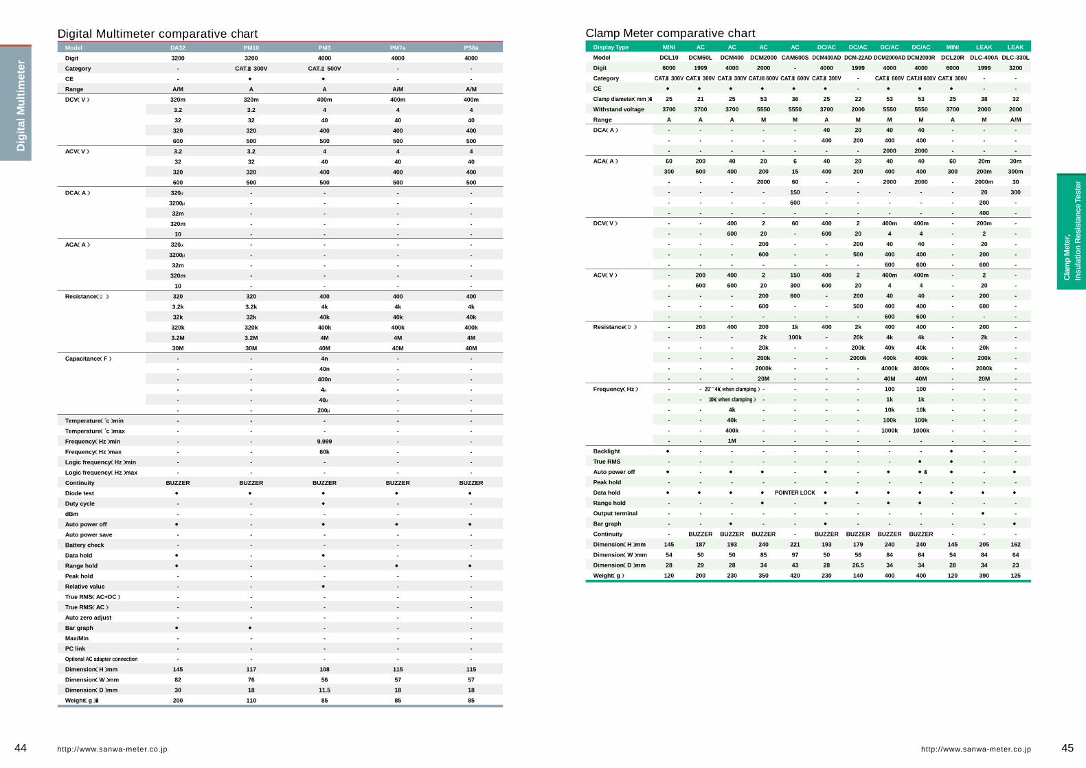
44 45http://www.sanwa-meter.co.jp http://www.sanwa-meter.co.jp
Display Type
Model
Digit
Category
CE
Clamp diameter(mm)�
Withstand voltage
Range
DCA(A)
ACA(A)
DCV(V)
ACV(V)
Resistance(Ω)
Frequency(Hz)
Backlight
True RMS
Auto power off
Peak hold
Data hold
Range hold
Output terminal
Bar graph
Continuity
Dimension(H)mm
Dimension(W)mm
Dimension(D)mm
Weight(g)
Clamp Meter comparative chartMINI
DCL10
6000
CAT. Ⅲ300V
●
25
3700
A
-
-
-
60
300
-
-
-
-
-
-
-
-
-
-
-
-
-
-
-
-
-
-
-
-
-
-
-
-
-
-
●
-
●
-
●
-
-
-
-
145
54
28
120
AC
DCM60L
1999
CAT. Ⅲ300V
●
21
3700
A
-
-
-
200
600
-
-
-
-
-
-
-
-
-
200
600
-
-
-
200
-
-
-
-
-
-
-
-
-
-
-
-
-
-
-
●
-
-
-
BUZZER
187
50
29
200
AC
DCM400
4000
CAT. Ⅲ300V
●
25
3700
A
-
-
-
40
400
-
-
-
-
400
600
-
-
-
400
600
-
-
-
400
-
-
-
-
-
20~4k(when clamping)
10k(when clamping)
4k
40k
400k
1M
-
-
●
-
●
-
-
●
BUZZER
193
50
28
230
AC
CAM600S
-
CAT. Ⅲ600V
●
36
5550
M
-
-
-
6
15
60
150
600
-
60
-
-
-
-
150
300
600
-
-
1k
100k
-
-
-
-
-
-
-
-
-
-
-
-
-
-
POINTER LOCK
-
-
-
-
221
97
43
420
DC/AC
DCM400AD
4000
CAT. Ⅲ300V
●
25
3700
A
40
400
-
40
400
-
-
-
-
400
600
-
-
-
400
600
-
-
-
400
-
-
-
-
-
-
-
-
-
-
-
-
-
●
-
●
●
-
●
BUZZER
193
50
28
230
DC/AC
DCM-22AD
1999
-
-
22
2000
M
20
200
-
20
200
-
-
-
-
2
20
200
500
-
2
20
200
500
-
2k
20k
200k
2000k
-
-
-
-
-
-
-
-
-
-
-
-
●
-
-
-
BUZZER
179
56
26.5
140
DC/AC
DCM2000AD
4000
CAT. Ⅲ600V
●
53
5550
M
40
400
2000
40
400
2000
-
-
-
400m
4
40
400
600
400m
4
40
400
600
400
4k
40k
400k
4000k
40M
100
1k
10k
100k
1000k
-
-
-
●
-
●
●
-
-
BUZZER
240
84
34
400
MINI
DCL20R
6000
CAT. Ⅲ300V
●
25
3700
A
-
-
-
60
300
-
-
-
-
-
-
-
-
-
-
-
-
-
-
-
-
-
-
-
-
-
-
-
-
-
-
●
●
●
-
●
-
-
-
-
145
54
28
120
LEAK
DLC-400A
1999
-
-
38
2000
M
-
-
-
20m
200m
2000m
20
200
400
200m
2
20
200
600
2
20
200
600
-
200
2k
20k
200k
2000k
20M
-
-
-
-
-
-
-
-
-
-
●
-
●
-
-
205
84
34
390
LEAK
DLC-330L
3200
-
-
32
2000
A/M
-
-
-
30m
300m
30
300
-
-
-
-
-
-
-
-
-
-
-
-
-
-
-
-
-
-
-
-
-
-
-
-
-
-
●
-
●
-
-
●
-
162
64
23
125
Model
Digit
Category
CE
Range
DCV(V)
ACV(V)
DCA(A)
ACA(A)
Resistance(Ω)
Capacitance(F)
Temperature( c゚)min
Temperature( c゚)max
Frequency(Hz)min
Frequency(Hz)max
Logic frequency(Hz)min
Logic frequency(Hz)max
Continuity
Diode test
Duty cycle
dBm
Auto power off
Auto power save
Battery check
Data hold
Range hold
Peak hold
Relative value
True RMS(AC+DC)
True RMS(AC)
Auto zero adjust
Bar graph
Max/Min
PC link
Optional AC adapter connection
Dimension(H)mm
Dimension(W)mm
Dimension(D)mm
Weight(g)�
DA32
3200
-
-
A/M
320m
3.2
32
320
600
3.2
32
320
600
320μ
3200μ
32m
320m
10
320μ
3200μ
32m
320m
10
320
3.2k
32k
320k
3.2M
30M
-
-
-
-
-
-
-
-
-
-
-
-
BUZZER
●
-
-
●
-
-
●
●
-
-
-
-
-
●
-
-
-
145
82
30
200
PM10
3200
CAT. Ⅲ300V
●
A
320m
3.2
32
320
500
3.2
32
320
500
-
-
-
-
-
-
-
-
-
-
320
3.2k
32k
320k
3.2M
30M
-
-
-
-
-
-
-
-
-
-
-
-
BUZZER
●
-
-
-
-
-
-
-
-
-
-
-
-
●
-
-
-
117
76
18
110
PM3
4000
CAT. Ⅱ500V
●
A
400m
4
40
400
500
4
40
400
500
-
-
-
-
-
-
-
-
-
-
400
4k
40k
400k
4M
40M
4n
40n
400n
4μ
40μ
200μ
-
-
9.999
60k
-
-
BUZZER
●
●
-
●
-
-
●
-
-
●
-
-
-
-
-
-
-
108
56
11.5
85
PM7a
4000
-
-
A/M
400m
4
40
400
500
4
40
400
500
-
-
-
-
-
-
-
-
-
-
400
4k
40k
400k
4M
40M
-
-
-
-
-
-
-
-
-
-
-
-
BUZZER
●
-
-
●
-
-
-
●
-
-
-
-
-
-
-
-
-
115
57
18
85
PS8a
4000
-
-
A/M
400m
4
40
400
500
4
40
400
500
-
-
-
-
-
-
-
-
-
-
400
4k
40k
400k
4M
40M
-
-
-
-
-
-
-
-
-
-
-
-
BUZZER
●
-
-
●
-
-
-
●
-
-
-
-
-
-
-
-
-
115
57
18
85
Digital Multimeter comparative chartD
igit
al M
ult
imet
er
Cla
mp
Met
er,
Insu
latio
n R
esis
tanc
e Te
ster
AC
DCM2000
2000
CAT.III 600V
●
53
5550
M
-
-
-
20
200
2000
-
-
-
2
20
200
600
-
2
20
200
600
-
200
2k
20k
200k
2000k
20M
-
-
-
-
-
-
-
-
●
-
●
●
-
-
BUZZER
240
85
34
350
DC/AC
DCM2000R
4000
CAT.III 600V
●
53
5550
M
40
400
2000
40
400
2000
-
-
-
400m
4
40
400
600
400m
4
40
400
600
400
4k
40k
400k
4000k
40M
100
1k
10k
100k
1000k
-
-
●
●�
-
●
●
-
-
BUZZER
240
84
34
400

Insulation Resistance Tester comparative chart
Display Type
Model
Category
CE
Test voltage range
Insulation resistance
(Rated voltage / Maximum scale value)
ACV(V)
DCV(V)
Discharge
Backlight
Inner battery check
Meter structure
Data hold
Auto power save
Auto power off
Dimension(H)mm
Dimension(W)mm
Dimension(D)mm
Weight(g)
DM1528S
CAT. Ⅲ600V
●
3
1000V/2000MΩ
500V/1000MΩ
250V/500MΩ
600
60
●
-
●
BAND
-
-
-
144
99
43
310
DM5218S
CAT. Ⅲ600V
●
3
500V/1000MΩ
250V/500MΩ
125V/200MΩ
600
60
●
-
●
BAND
-
-
-
144
99
43
310
DM1008S
CAT. Ⅲ600V
●
1
1000V/2000MΩ
-
-
600
60
●
-
●
BAND
-
-
-
144
99
43
310
DM508S
CAT. Ⅲ600V
●
1
500V/1000MΩ
-
-
600
60
●
-
●
BAND
-
-
-
144
99
43
310
PDM508S
CAT. Ⅲ600V
●
1
500V/100MΩ
-
-
600
60
●
-
●
BAND
-
-
-
144
99
43
310
DM-1527
-
-
3
1000V/2000MΩ
500V/1000MΩ
250V/500MΩ
600
-
●
-
●
BAND
-
-
-
175
118
55
520
DM-5257
-
-
3
500V/1000MΩ
250V/500MΩ
100V/200MΩ
600
-
●
-
●
BAND
-
-
-
175
118
55
520
Display Type
Model
Category
CE
Test voltage range
Insulation resistance
(Rated voltage / Maximum scale value)
ACV(V)
DCV(V)
Discharge
Backlight
Inner battery check
Meter structure
Data hold
Auto power save
Auto power off
Dimension(H)mm
Dimension(W)mm
Dimension(D)mm
Weight(g)�
DG6
-
-
2
25V/4M・40M
15V/4M・40M
-
-
-
-
-
-
●
●
-
117
76
18
125
DG7
-
-
2
50V/4M・40M
25V/4M・40M
-
-
-
-
-
-
●
●
-
117
76
18
125
DG8
-
-
2
50V/4M・40M
15V/4M・40M
-
-
-
-
-
-
●
●
-
117
76
18
125
DG9
-
-
2
125V/40M・400M
50V/4M・40M
-
-
-
-
-
-
●
●
-
117
76
18
125
DG525
-
-
2
500V/2000MΩ
250V/2000MΩ
600
-
-
●
-
-
●
-
●
175
115
55
600
DG251
-
-
2
250V/2000MΩ
125V/2000MΩ
600
-
-
●
-
-
●
-
●
175
115
55
600
M53
-
-
2
500V/200MΩ
15V/20MΩ
750
750
-
-
-
-
-
-
●
175
115
55
600
46 47http://www.sanwa-meter.co.jp http://www.sanwa-meter.co.jp
Model
Category
CE
DCV(V)
ACV(V)
DCA(A)
ACA(A)
Resistance(Ω)
Capacitance(F)
Auto range
Low frequency output measurement
Continuity
Battery check
Auto polarity
Meter structure
Drop shock proof meter
Zero center meter
Temperature measurement
Protection circuit for power line
hFE
Dimension(H)mm
Dimension(W)mm
Dimension(D)mm
Weight(g)
EM7000
CAT. Ⅲ600V
●
0.3
1.2
3
12
30
120
300
1000
3
12
30
120
300
750
0.12μ
0.3m
3m
30m
300m
6
6
-
-
-
-
2k
20k
200k
2M
20M
200M
-
-
-
-
-
●
-
-
-
BAND
-
●
-
-
-
165
106
46
375
CX506a
CAT. Ⅲ600V
●
120m
3
12
30
120
300
1000
-
3
12
30
120
300
750
30μ
0.3m
3m
30m
0.3
-
-
-
-
-
-
5k
50k
500k
5M
50M
-
0.2μ
20μ
2000μ
-
-
-
-
-
-
BAND
-
-
-
-
●
165
106
46
370
YX-361TR
-
-
0.1
0.5
2.5
10
50
250
1000
-
2.5
10
50
250
1000
-
50μ
2.5m
25m
0.25
-
-
-
-
-
-
-
2k
20k
200k
2M
20M
-
-
-
-
-
-
●
LED
1.5V
-
PIVOT
-
●
-
-
○
150
100
37
290
SH-88TR
-
-
120m
3
12
30
120
300
1200
-
3
12
30
120
300
1200
50μ
3m
30m
0.3
-
-
-
-
-
-
-
3k
30k
300k
3M
30M
-
1000μ
0.01
0.1
1
-
●
LED
-
-
PIVOT
-
●
-
-
○
150
100
36
280
AU-32
-
-
250m
2.5
10
50
250
500
-
-
250m
2.5
10
50
250
500
250μ
2.5m
25m
250m
2.5
-
250μ
2.5m
25m
250m
2.5
20k
200k
2M
20M
200M
-
-
-
-
-
●
●�
-
-
●
PIVOT
-
-
-
-
-
48
110
124
290
AU-31
-
-
300m
3
12
60
300
1000
-
-
300m
3
12
60
300
1000
300m
3
-
-
-
-
300m
3
-
-
-
20k
200k
2M
20M
200M
-
-
-
-
-
●
●
-
-
●
PIVOT
-
-
-
-
-
48
110
124
290
YX360TRF
CAT. Ⅲ600V
●�
0.1
0.25
2.5
10
50
250
1000
-
10
50
250
750
-
-
50μ
2.5m
25m
0.25
-
-
-
-
-
-
-
2k
20k
200k
2M
200M
-
10μ
-
-
-
-
●�
-
-
-
BAND
●�
●�
-
-
○�
159.50
129
41.50
320
SP21
CAT. Ⅲ600V
●
0.3
3
12
30
120
600
-
-
12
30
120
300
600
-
60μ
30m
0.3
-
-
-
-
-
-
-
-
2k
20k
2M
-
-
-
500μ
-
-
-
-
-
BUZZER
1.5V
-
BAND
●
●
-
-
-
144
99
41
270
Analog Multitester comparative chart
○ Optional accessory is necessary.
Cla
mp
Met
er,
Insu
latio
n R
esis
tanc
e Te
ster
An
alo
g M
ult
ites
ter
DIGITAL
ANALOG

ISO 9001(Quality assurance)
Traceability
Repairs andservicing
The manufacturing plant of Sanwa Tesmex Co.,
Ltd. obtained ISO9002 certification from the
foundation "Japan Quality Assurance Organiza-
tion(JQA)" in 1996. In October 2002, Sanwa
Electric Instrument Co., Ltd. was organized as
one company incorporating the manufacturing
division and sales division. In November 2002,
the company obtained ISO9001: 2000 certifica-
tion (JQA-1453). �
The scope of the registration covers the design,
development, production and servicing of multi-
meters, clamp meters, insulating-resistance tes-
ters, standard generators, light power meters,
and laser power meters.
Traceability to prove the compliance with national and international standards is an es-
sential factor for measuring instruments used as test instruments associated with quality
assurance. Products of Sanwa are calibrated by reference samples which is periodically
checked for its compliance with national standards. A calibration certificate and test data
report are available on your request(a fee applies).
Please contact an agent of Sanwa in your country for periodic calibration and repairs,
which are offered on a chargeable basis. Please refer to the website of Sanwa for Sanwa's
authorized agents.
Traceability Flow Chart
National Institute of Advanced IndustrialScience and Technology(AIST)�
Communications ResearchLaboratory(CRL)�
National Institute ofStandards and
Technology(NIST)�Japan Electric Meter InspectionCorporation(JEMIC)�
Public Institution, Maker
Multifunction Calibrator(AC/DC Voltage
and Current)�
Precision DigitalMultimeter
Precision Digital Multimeter
Instruments used in Design and Development, Production, Inspection, and Service department
SANWA Products(Digital Multimeter, Analog Multitester, Clamp Meter, Insulation Resistance Tester, Thermo Meter, and etc.)�
StandardResistor
StandardCapacity
FrequencyCounter
StandardThermo-
meter
ReferenceResistorStandard
AC/DC StandardVoltage and
Current generator
DC StandardVoltage and
Current generator
AC StandardVoltage and
Current generator
DigitalStandardCapacitor
DialStandardResistor
Transmitter
ReferenceVoltage
Standard
An
alo
g M
ult
ites
ter
48 49http://www.sanwa-meter.co.jp http://www.sanwa-meter.co.jp
Model
Category
CE
DCV(V)
ACV(V)
DCA(A)�
ACA(A)
Resistance(Ω)
Capacitance(F)
Auto range
Low frequency output measurement
Continuity
Battery check
Auto polarity
Meter structure
Drop shock proof meter
Zero center meter
Temperature measurement
Protection circuit for power line
hFE
Dimension(H)mm
Dimension(W)mm
Dimension(D)mm
Weight(g)
Analog Multitester comparative chartSP20
-
-
0.25
2.5
5
10
50
100
500
10
50
250
500
-
50μ
2.5m
25m
0.25
-
2k
20k
200k
2M
500μ
-
-
-
1.5V
-
BAND
●
-
○
-
-
144
99
41
270
SP-18D
-
-
0.3
3
12
30
120
600
-
12
30
120
300
600
60μ
30m
300m
-
-
2k
20k
200k
2M
1000μ
-
-
-
1.5V
-
BAND
●
-
-
-
-
159.5
129
41.5
320
TA55
-
-
0.3
3
16
30
60
-
-
30
120
300
-
-
0.5
3
30
-
-
2k
20k
200k
2M
-
-
-
BUZZER
12V
-
BAND
●
-
-
-
-
142
97
38
300
CP-7D
-
-
0.25
2.5
10
50
250
500
-
10
50
250
500
-
0.25m
25m
500m
-
-
2k
20k
1M
-
-
-
●
-
1.5V
-
PIVOT
-
-
-
-
-
119
85
23
140
PW-100Fb
-
-
0.1
1
5
50
250
750
-
6
30
300
600
-
-
-
-
-
-
5k
500k
5M
-
-
-
-
-
-
-
PIVOT
-
-
-
●
-
150
100
36
280
VS-100
-
-
10
50
250
500
-
-
-
10
50
250
500
-
-
-
-
-
-
2k
20k
2M
-
-
-
-
-
-
-
PIVOT
-
-
-
●
-
144
96
56
400
AP33
CAT. Ⅲ300V
-
10
50
250
500
-
-
-
50
250
500
-
-
25m
250m
-
-
-
5k
500k
-
-
-
-
-
-
1.5V/9V
-
PIVOT
-
-
-
-
-
126
87
30
185
○ Optional accessory is necessary.

Safety
◆ Method for safe use of measuring instrument ◆
For safe measurement
The International Safety Standard IEC61010This Safety Standard which is established for protecting operators and environment stipulates safety requirements for measuring in-struments and electric equipment. The IEC standard defines the degree of pollution, measurement classification, barrier, material, spatial distance and creepage distance to assure safety. The im-pulse withstand voltage as transitional energy is estimated from the measurement category and main power supply voltage to con-duct tests for measuring instruments.
MultimeterVoltage measurementNever use a measuring instrument for a measurement category higher than speci-fied. A tester not conforming to the interna-tional safety standard is for use with weak current. Never use these testers on a high power circuit of 250V or more (excluding PW-100Fb,VS-100). Referring to measure-ment categories defined in the IEC stan-dard, use a measuring instrument of equiva-lent or higher category. For instance, when a measuring instrument is used on a motor of facility of 200V main power supply, which corresponds to CategoryⅢ, use a measur-ing instrument of CAT.Ⅲ or higher.�Current measurementUse special caution not to input voltage to the current measuring terminal in measure-ment. In current measurement, a meter is connected in series with the measuring cir-cuit. For this reason, impedance inside the meter is low, thereby possibly causing a short-circuit fault. To prevent such a short-circuit fault and assure safe operation, fuses are installed for protection. Check the pro-tection capability of the fuses. RD700 uses a quick-breaking ceramic fuse of rated vol-tage 250V and breaking current 1.5kA for the milliamp measuring circuit, which cau-ses the fuse to blow out to prevent short-cir-cuit when the main power supply is 250V or less and short circuit current is 1.5kA or less.
Clamp meter●Use all clamp meters for measurement of low voltage circuit of 600V or less.�●In choosing an appropriate model, special attention should be paid to the current measurement range and diameter of a conductor to be clamped.�Insulation resistance tester ●The insulation resistance tester cannot be used on an measuring object in live-wire status.�●If the measuring voltage is specified, choose a model of the specified voltage.� It is a general practice to choose the measuring voltage equivalent to or a little higher than voltage usually applied to the measuring object.�●Since the insulating-resistance tester� measures resistance values by applying DC high voltage on a measuring object, the measurement may damage the meas uring object if voltage is directly applied on he electronic circuit including the IC and LSI.�●The insulating-resistance tester generates DC high voltage during measurement. If an electric shock occurs, a falling accident from a high altitude may follow. Use special caution in operation at a high altitude.�●If your measuring instrument is provided with a voltage measuring function, use it at no higher than the maximum measuring voltage.
Thermo Meter(Temperature Probe)●The temperature sensor cannot be used for measurement in direct contact with a live part.�●Use caution in handling a sharp-edged probe to avoid an injury.�●The grip is heated in high temperature measurement. Use an appropriate jig to secure the probe in high temperature measurement.�Tachometer ・ Speed Meter●In measurement on a rotating motor (m- easurement of speed for elevator in opera- tion), risks are involved due to the strong force of the measuring object. Use special caution in measurement to assure safety. Never touch the rotating part during meas- urement. �Laser Power Meter●Infrared semiconductor laser light is invisi ble to the naked eye. It may occasionally emit high power of 30mW or more, which may threaten vision if eyes are exposed to the light. Use special caution to avoid gaz- ing at the light directly or exposing eyes to reflected light.
Measurement category(overvoltage category)The IEC standard classifies measuring circuits according to measure-ment categories for the safe use of a measuring instrument in low vol-tage facilities. The measurement categories are classified into I to IV. A larger number of the category denotes a spot involving higher tran-sient energy. For safe measurement, wear protective gears such as insulated gloves and dust-proof glasses in an environment of CAT.Ⅲ.�Measurement category Ⅳ(CAT. Ⅳ):Equipment used for measurement in low voltage facilities.�Temporary overcurrent preventer, and electric measurement on rip-ple control unit, etc.�Measurement category Ⅲ(CAT. Ⅲ):Equipment used for measurement in building facilities�Distribution board, circuit breaker, wiring including cables, busbar, junction box, switch, receptacle, and industrial equipment located in fixed facilities, and other equipment such as a fixed motor connected to fixed facilities in a permanent manner.�Measurement category Ⅱ(CAT. Ⅱ):Equipment used for measurement performed on a circuit directly con-nected to low voltage facilities�Measurement on electric household appliances, portable tools and similar tools�Measurement category Ⅰ(CAT. Ⅰ):Equipment used for measurement on a circuit not directly connected to main power supply�Circuit not derived from the main power supply
CE markingCE marking is a safety mark which can be attached only on a product meeting the safety requirements of the Di-rective of Council of the European Union (EC Directive).
A product attached with the CE mark is designed so as to meet the requirements of the "Low Voltage Directive" and "EMC Directive" of the EC Directive. Low Voltage Directive: This Directive covers prod-ucts of power supply voltage of 50V-1000V(AC)and 75V-1500V(D-C), and it defines electric safety requirements against shocks, burns, etc. The applicable standard is EN61010 corresponding to IEC1010 give on the left. EMC Directive: This Directive stipulates conditions so as not to give out strong electromagnetic waves from equipment to the outer environment and to protect equipment from the effect of electromagnetic waves from the outside.
Test voltage (impulse withstand voltage)
300V �600V�1000V
Nominal AC or DC line ofmain power�supply andneutral voltage CAT.Ⅱ�
2500V�4000V�6000V
CAT.Ⅲ�
4000V �6000V�8000V
CAT.Ⅳ�
6000V �8000V�12000V
The output impedance of an impulse generator is 12Ω in the measurement categoryⅡ, and 2Ω in measurement�categories Ⅲ and Ⅳ.
Watthourmeter
Power�receptacle��
Powerreceptacle
CAT.Ⅲ CAT.Ⅱ
CAT.ⅠCAT.Ⅳ
Indoor wiring
Distributionboard
Serviceentrance
Servicewire
■Accuracy / ToleranceCorrectness. JIS defines the term "accuracy" to be used for digital tes-ters and "tolerance" for analog tes-ters. The accuracy / tolerance differs depending on the range.��■±(□%+□)=±(□%rdg+□dgt)�rdg is an abbreviation of "Reading" meaning a read value on digital dis-play. "dgt" is an abbreviation of "Digit" meaning the least unit of digital dis-play. For instance, "±2dgt" refers to error of ±2 counts.��■Full-scale value(fs)It is the indication of tolerance ex-pressed by percentage values relative to the full-scale value of the range.��■Scale lengthThe tolerance in resistance measure-ment is expressed with reference to the scale length of the range.��■Frequency characteristic�Frequency range of measurable sig-nals in the measurement of AC vol-tage and current.��■Input resistance(Imped-ance)Internal resistance between measur-ing terminals. For instance, it is ex-pressed as "MΩ" with the DMM and as "KΩ/V" with the AMT.��■Clamp diameterIt gives a guide for the thickness of a clampable wire.��■Clamp conductor size�Size of a maximum conductor shape.��■Withstand voltageIt refers to insulating withstand vol-tage of the measuring instrument it-self.��■RangeThe measuring range of a function is sub-divided and expressed as 2V/20V/200V, etc.��■Auto rangeThe range is automatically increased or decreased in steps such as 2V/20V/200V and moves to the opti-mum range for measuring voltage. ��■Live-wire checkWhen a test lead is set at an insulat-ing resistance measuring point on a measuring object, the ACV measuring status starts to check whether voltage is being supplied. ��■Display digitMaximum number of display digits of the digital display. 1999 is expressed as 2000. Three and a half digits and four and a half digits are also used.��■FunctionFunction for measuring voltage, cur-rent, resistance, electrostatic capacity and frequency. ��■ResolutionDisplayable minimum value of the last digit. For instance, the resolution of the 1.999V range is 0.001V.
True RMS (True root-mean-square value)True RMS value. AC cur-
rent and voltage of a non-sine wave can be measured by true RMS val-ues.
Data holdA value indicated on the display is fixed. It is fixed
even after the test lead is removed, and can be used as a record for ref-erence purposes.
DC / AC measurableBoth ACA and DCA are measurable.
Drop shock proofThe meter element is furn-ished with a taut band and
impact-resistant design enough to withstand a shock of drop.
Low power ohmResistance is measured by applying voltage of approxi-
mately 0.4V or less on a measuring object. It is characterized by the fact that the semiconductor does not conduct at approximately 0.4V or less even in forward direction.
BacklightAllows indicator reading in a dark place.
Leakage currentA clamp meter that can make the measurement of
leakage current have a range to al-low measurements in milliamp.
Output terminalCancels the DC current portion of voltage mixed
with DC and AC to measure the AC portion alone. It is used for the measurement of audio signals.
Auto dischargeWhen the measurement of insulating resistance is
complete, voltage charged in the measuring object is discharged.
Scale lightingThis is a function for light-ing the scale plate. It is the
same function as the backlight func-tion of digital display of the LCD.
RS232C connectionThe signal output terminal is provided to send data to
a PC. RS232C is the name of the signal standard.
USB connectionData can be outputted by connection to the USB
port of a PC.
Fuse for power sup-plyCurrent-limiting fuse to
break the conduction up to 100kA
Insulating resis-tanceInsulating resistance can
be measured(e.g. 500V/1000MΩ)�
DC voltageMark for clamp meters with DCV function.
Range holdThe range is fixed in the measurement of varying
voltage and current which is difficult to read in the auto range.
Measurement of relative valueA certain measured value
is assumed as 0 and measured val-ues after that are expressed by posi-tive or negative values relative the value fixed as 0.
Duty cycleThe duty cycle of repeat-ing waveform is indicated
on a percentage basis(%). It can be used for the analysis of control signals.
Capture(peak hold)The peak value like in-rush current is indicated. The minimum pulse width capturable differs according to models.
MAX / MINThe minimum value and maximum value of meas-
ured values are recorded. The recor-ded values can be seen later on the display.
Maximum value holdThe maximum value is held and displayed in the
measurement of voltage, current and ADP.
Zoom bar graphThe scale is changed so as to allow reading minute
changes on the bar graph.
Correction of resis-tance of test leadThis is a function to cancel
the resistance portion of the internal circuit of the main body and test lead in the resistance measurement.
Auto polarityPuts the indicator at the cen-ter in the automatic standby
status by the setting of the selector switch so as to allow measurement by positive and negative values.
Polarity switchThe positive and negative polarity of the measuring
terminal can be changed by this switch.
Zero-ohm adjusterCancels the contact resis-tance and internal resis-
tance of the test lead to allow the measurement of the resistance val-ue of a measuring object alone.
Zero-center meter(NULL)Moves the indicator of the analog tester to the center
of the scale(meter graduations)to make measurement of positive and negative voltage.
FrequencyExpressed in the unit of Hz (hertz). Commercial fre-
quency of 50Hz/60Hz can be meas-ured.
Capacitor Capacitor capacity(elect-rostatic capacity)is meas-
ured and expressed in the unit of F(farad), μF, etc.
Continuity checkThe LED lights up when the measuring object is
electrically conducting.
Continuity buzzerThe buzzer sounds when the measuring object is
electrically conducting.
Battery checkBattery voltage is meas-ured and assessed by run-
ning a given current.
hFEProvided with graduations for measuring the DC cur-
rent amplification factor(hFE)of a transistor.
4-20mA%4-20mA for sending instru-mentation signals. Expres-
ses the current loop of 4mA as 0% and 20mA as 100%
dBmScaling of voltage values is performed according to
the reference impedance into dBm. Convenient for use with audio equip-ment.
Temperature measurementTemperature can be
measured using the optional probe.
Temperature measurementwith PC Link
Temperature can be measured using the optional probe and PC Link software.(T-300PC is necessary.)�
Auto power offPower is automatically turned off when a certain
time has elapsed after power-up. Some models have a function to cancel this function.
Auto power save�The display disappears to bring the device into the pow-
er-save state when a certain time has passed after power-up. Some models have a function to cancel this function.
F u n c t i o n m a r k s G l o s s a r y
Function marks and terminology used in General Catalog
DCAACA
50 51http://www.sanwa-meter.co.jp http://www.sanwa-meter.co.jp