Embed Size (px)
Citation preview
Firmware and User Manual - stdMifareV2.0.x
Release 1.2.0
SonMicro Elektronik
Nov 07, 2017

CONTENTS
1 WARNINGS - Mifare Card Usage 1
2 INTRODUCTION 32.1 Firmware Version History . . . . . . . . . . . . . . . . . . . . . . . . . . . . . . . . . . . . . . . 4
3 FUNCTIONALITY & OPERATION MODES 53.1 Standard Mode . . . . . . . . . . . . . . . . . . . . . . . . . . . . . . . . . . . . . . . . . . . . . 63.2 Auto Mode . . . . . . . . . . . . . . . . . . . . . . . . . . . . . . . . . . . . . . . . . . . . . . . . 63.3 SREAD & TAGF Pin/LED Functionality . . . . . . . . . . . . . . . . . . . . . . . . . . . . . . . 73.4 OUT3 (BUZZER) Pin Functionality . . . . . . . . . . . . . . . . . . . . . . . . . . . . . . . . . . 83.5 RS485 Operation . . . . . . . . . . . . . . . . . . . . . . . . . . . . . . . . . . . . . . . . . . . . 9
3.5.1 RS485 BIDIRECTIONAL & POLLING MODES . . . . . . . . . . . . . . . . . . . . . 103.6 I2C Operation (Slave) . . . . . . . . . . . . . . . . . . . . . . . . . . . . . . . . . . . . . . . . . 11
4 DEVICE CONFIGURATION 134.1 Ordering Configuration Code . . . . . . . . . . . . . . . . . . . . . . . . . . . . . . . . . . . . . 14
4.1.1 Template Configuration Selection FlowChart for Standard Mode . . . . . . . . . . . . 144.1.2 Template Configuration Selection FlowChart for Auto Mode . . . . . . . . . . . . . . . 154.1.3 Template Configuration Selection FlowChart for Backward Compatibility . . . . . . . 164.1.4 Default Configuration Templates . . . . . . . . . . . . . . . . . . . . . . . . . . . . . . . 174.1.5 Backward Compatible Configurations (TYPE A CONNECTION / DC BUZZER) . . . 254.1.6 Ordering Code Structure . . . . . . . . . . . . . . . . . . . . . . . . . . . . . . . . . . . 28
5 stdMifare V2.0.x COMMANDS 335.1 Command List - Mifare Card Operations . . . . . . . . . . . . . . . . . . . . . . . . . . . . . . 345.2 Command List - Hardware Control & Configuration . . . . . . . . . . . . . . . . . . . . . . . . 345.3 CmdActivateAll . . . . . . . . . . . . . . . . . . . . . . . . . . . . . . . . . . . . . . . . . . . . . 355.4 CmdSeekForTag . . . . . . . . . . . . . . . . . . . . . . . . . . . . . . . . . . . . . . . . . . . . 375.5 CmdActivateIdle . . . . . . . . . . . . . . . . . . . . . . . . . . . . . . . . . . . . . . . . . . . . 395.6 CmdHalt . . . . . . . . . . . . . . . . . . . . . . . . . . . . . . . . . . . . . . . . . . . . . . . . . 415.7 CmdAuthenticate . . . . . . . . . . . . . . . . . . . . . . . . . . . . . . . . . . . . . . . . . . . . 435.8 CmdReadBlock . . . . . . . . . . . . . . . . . . . . . . . . . . . . . . . . . . . . . . . . . . . . . 455.9 CmdWriteBlock . . . . . . . . . . . . . . . . . . . . . . . . . . . . . . . . . . . . . . . . . . . . . 475.10 CmdWriteBlock4Byte . . . . . . . . . . . . . . . . . . . . . . . . . . . . . . . . . . . . . . . . . 495.11 CmdReadValueBlock . . . . . . . . . . . . . . . . . . . . . . . . . . . . . . . . . . . . . . . . . . 505.12 CmdWriteValueBlock . . . . . . . . . . . . . . . . . . . . . . . . . . . . . . . . . . . . . . . . . 515.13 CmdIncrementValueBlock . . . . . . . . . . . . . . . . . . . . . . . . . . . . . . . . . . . . . . . 535.14 CmdDecrementValueBlock . . . . . . . . . . . . . . . . . . . . . . . . . . . . . . . . . . . . . . . 555.15 CmdReset . . . . . . . . . . . . . . . . . . . . . . . . . . . . . . . . . . . . . . . . . . . . . . . . 575.16 CmdGetFirmwareVersion . . . . . . . . . . . . . . . . . . . . . . . . . . . . . . . . . . . . . . . 58
i
5.17 CmdStoreKeyInFlash . . . . . . . . . . . . . . . . . . . . . . . . . . . . . . . . . . . . . . . . . . 595.18 CmdAntennaPower . . . . . . . . . . . . . . . . . . . . . . . . . . . . . . . . . . . . . . . . . . . 605.19 CmdReadInput . . . . . . . . . . . . . . . . . . . . . . . . . . . . . . . . . . . . . . . . . . . . . 615.20 CmdWriteOutput . . . . . . . . . . . . . . . . . . . . . . . . . . . . . . . . . . . . . . . . . . . . 625.21 CmdSetBaudRate . . . . . . . . . . . . . . . . . . . . . . . . . . . . . . . . . . . . . . . . . . . . 635.22 CmdSetI2CAddress . . . . . . . . . . . . . . . . . . . . . . . . . . . . . . . . . . . . . . . . . . . 655.23 CmdGetI2CAddress . . . . . . . . . . . . . . . . . . . . . . . . . . . . . . . . . . . . . . . . . . 665.24 CmdPollBuffer . . . . . . . . . . . . . . . . . . . . . . . . . . . . . . . . . . . . . . . . . . . . . 675.25 CmdAdvancedOutputDrive . . . . . . . . . . . . . . . . . . . . . . . . . . . . . . . . . . . . . . 695.26 CmdGetAppConfig . . . . . . . . . . . . . . . . . . . . . . . . . . . . . . . . . . . . . . . . . . . 745.27 CmdSetAppConfig . . . . . . . . . . . . . . . . . . . . . . . . . . . . . . . . . . . . . . . . . . . 75
5.27.1 Config Data Frame . . . . . . . . . . . . . . . . . . . . . . . . . . . . . . . . . . . . . . . 75
6 TRADEMARKS 79
7 DOCUMENT REVISON HISTORY 81
ii
CHAPTER
ONE
WARNINGS - MIFARE CARD USAGE
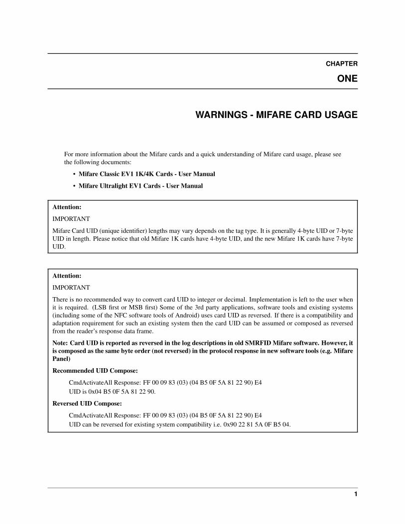
For more information about the Mifare cards and a quick understanding of Mifare card usage, please seethe following documents:
• Mifare Classic EV1 1K/4K Cards - User Manual
• Mifare Ultralight EV1 Cards - User Manual
Attention:
IMPORTANT
Mifare Card UID (unique identifier) lengths may vary depends on the tag type. It is generally 4-byte UID or 7-byteUID in length. Please notice that old Mifare 1K cards have 4-byte UID, and the new Mifare 1K cards have 7-byteUID.
Attention:
IMPORTANT
There is no recommended way to convert card UID to integer or decimal. Implementation is left to the user whenit is required. (LSB first or MSB first) Some of the 3rd party applications, software tools and existing systems(including some of the NFC software tools of Android) uses card UID as reversed. If there is a compatibility andadaptation requirement for such an existing system then the card UID can be assumed or composed as reversedfrom the reader’s response data frame.
Note: Card UID is reported as reversed in the log descriptions in old SMRFID Mifare software. However, itis composed as the same byte order (not reversed) in the protocol response in new software tools (e.g. MifarePanel)
Recommended UID Compose:
CmdActivateAll Response: FF 00 09 83 (03) (04 B5 0F 5A 81 22 90) E4UID is 0x04 B5 0F 5A 81 22 90.
Reversed UID Compose:
CmdActivateAll Response: FF 00 09 83 (03) (04 B5 0F 5A 81 22 90) E4UID can be reversed for existing system compatibility i.e. 0x90 22 81 5A 0F B5 04.
1
Firmware and User Manual - stdMifare V2.0.x, Release 1.2.0
Attention:
IMPORTANTIt is strongly recommended not to use tag type byte (reported in activate command) in your application.It is not a part of card UID and its consistency in new firmware releases is not guaranteed.
Attention:
IMPORTANT
For critical applications where card data blocks are written frequently, it is recommended to backup copy of thecard block in another sector and design your application accordingly, dealing with two sectors. There are Mifarecards from different manufacturers in the market with poor writing performance. These cards may erase the blockcontent (full of 0x00 or 0xFF) while the write operation is interrupted during the milliseconds time frame. Thismay happen when the card is being moved from out of RF field while the data is being written to the flash memoryof the card. Card may have no power to sustain write operation.
Attention:
IMPORTANTIt is strongly recommended to change all the factory default sector keys (Default: 0xFF FF FF FF FF FF) of theMifare cards before use in the customer field.
2 Chapter 1. WARNINGS - Mifare Card Usage
CHAPTER
TWO
INTRODUCTION
This document explains the followings for 13.56MHz Mifare® Module or Reader that runs the stdMifare V2.0.xfirmware version.
• Functional features and operation modes
• Configuration of the module/reader
• Full Command API
– For Mifare card operations (i.e. activate/authenticate/read/write card blocks)
– For controlling and configuring the module/reader and I/O.
Note:
• For UART/I2C communication protocol details please see the Mifare® Readers UART/I2C CommunicationProtocol – SPV1 document.
• For hardware specifications please refer module/reader datasheet or hardware manual.
• For quick understanding of Mifare cards, please see the Mifare Classic EV1 1K/4K Cards - User Manualdocument.
stdMifare firmware version is a cumulative improvement and collection of most demanded features since 2004 andruns on second generation hardware (SM521x core).
It holds configurable all-in-one features appropriate for access control, payment and general-purpose applications withUART (Including RS232, RS485 and USB Virtual Com port) and I2C communication support.
stdMifare firmware version can be configured to be compatible with the previous firmware versions.
stdMifare firmware version is integrated with a bootloader program. Second generation modules or readers withSM521X core module(i.e. UM1.3R 1.0.7/1.1.4) can be upgraded to the stdMifare firmware version.
stdMifare firmware version does not introduce any bug fix; thus, you can reliably use the previous firmware versionsfor the existing applications. However please notice that all the new documentation, application notes and the hardwaredevelopment (base board, readers etc.) will be based on the latest firmware version.
3
Firmware and User Manual - stdMifare V2.0.x, Release 1.2.0
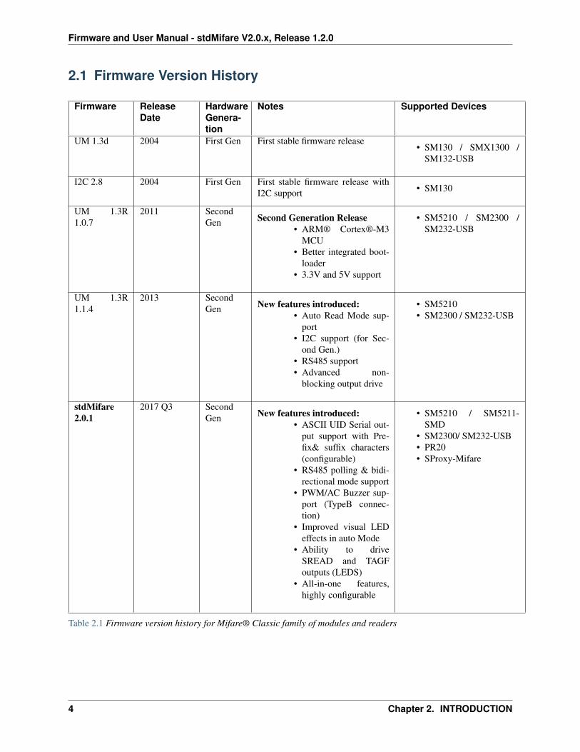
2.1 Firmware Version History
Firmware ReleaseDate
HardwareGenera-tion
Notes Supported Devices
UM 1.3d 2004 First Gen First stable firmware release• SM130 / SMX1300 /
SM132-USB
I2C 2.8 2004 First Gen First stable firmware release withI2C support • SM130
UM 1.3R1.0.7
2011 SecondGen Second Generation Release
• ARM® Cortex®-M3MCU
• Better integrated boot-loader
• 3.3V and 5V support
• SM5210 / SM2300 /SM232-USB
UM 1.3R1.1.4
2013 SecondGen New features introduced:
• Auto Read Mode sup-port
• I2C support (for Sec-ond Gen.)
• RS485 support• Advanced non-
blocking output drive
• SM5210• SM2300 / SM232-USB
stdMifare2.0.1
2017 Q3 SecondGen New features introduced:
• ASCII UID Serial out-put support with Pre-fix& suffix characters(configurable)
• RS485 polling & bidi-rectional mode support
• PWM/AC Buzzer sup-port (TypeB connec-tion)
• Improved visual LEDeffects in auto Mode
• Ability to driveSREAD and TAGFoutputs (LEDS)
• All-in-one features,highly configurable
• SM5210 / SM5211-SMD
• SM2300/ SM232-USB• PR20• SProxy-Mifare
Table 2.1 Firmware version history for Mifare® Classic family of modules and readers
4 Chapter 2. INTRODUCTION
CHAPTER
THREE
FUNCTIONALITY & OPERATION MODES
stdMifare firmware version supports all operations such as authenticate/read/write for the Mifare® Classic 1K, Mi-fare® Classic 4K and Mifare® Classic Ultralight tags. NTAG®, ISO14443A NFC Tags are also supported. SeeLimitations:1
stdMifare firmware version supports also reading card serial number, UID (Unique Identifier) of all ISO14443Acards i.e. Mifare® DESFire, Mifare® Plus, Mifare® Ultralight C. However, authenticate/read/write operations are notsupported with these cards.
stdMifare firmware version handles the ISO14443A RFID protocol and provide easy to use communication interface,UART & I2C2 with well-defined protocol, SPV13 and rich command set. Firmware provides commands such asactivate, authenticate, read/write data block and more to interact with the Mifare card and the hardware. A contactlesssmart card application can be designed easily with a microcontroller or PC with the provided commands and SDKs(i.e. QT(C++), Python, .Net)
stdMifare firmware version provides two operation modes, Standard Mode and Auto Mode. Operation modes andother settings can be configured with relevant command API or software tools.
External controller or device can be a microcontroller with UART or I2C interface or a device (i.e. PC) withRS232/RS485/USB interface. RS232/RS485 and USB-UART are based on UART communication protocol and properhardware interface is required between the communicating devices. For communication interface and the electricalcharacteristics, hardware manual of the target module/reader must be checked.
SonMicro provides ready-to-use base boards and kits for the SM521x modules and also provides complete readers thatare integrated with power supply, antenna and different hardware communication interfaces for different requirements.
Note:
• In addition to UART/I2C/RS232/RS485/USB, modules and readers support Wiegand protocol but not imple-mented in the stdMifare firmware version. For Wiegand interface ask for a supporting firmware version.
Note:
• stdMifare firmware has built in watchdog timer enabled and can recover from an unexpected condition with asoftware reset.
1 NTAG, ISO14443A NFC tags can be read/write with the standard firmware versions but some NFC specific features have not been availableyet. UID reading of these cards are straight forward.
2 I2C is not enabled in default. It needs to be enabled thru configuration or it should be requested to be enabled when shipping from the factory.3 Spv1 - Standard Protocol Version 1 is name of the protocol used with the Mifare Module UART and I2C communication. Please see Mifare
Readers Communication Protocol document for more details.
5
Firmware and User Manual - stdMifare V2.0.x, Release 1.2.0
3.1 Standard Mode
In standard mode all operations including the card UID reading, authenticate/read/write card blocks are controlled byan external controller with command-response manner. Standard mode is appropriate if you interact with the cardblocks and/or want to manage control flow by an external controller.
For a full list of command and API, please see STDMIFARE COMMANDS
3.2 Auto Mode
In Auto mode, the card UID (card serial number - unique identifier) is read automatically (no need to send commandby an external device) and reported over serial communication channel (UART) asynchronously. Card UID can bereported as SPV1 protocol, or as in ASCII character format with some useful options i.e. appending prefix, suffix,Carriage Return (CR) and Line Feed (LF) characters.
Auto mode continuously run inside a loop and tries to activate a card. Once a card is activated it is reported only onetime and will not be reported again while the card is still in RF field.
Auto mode is appropriate for basic access control applications, or if you are only interested to read card UID automat-ically whenever it is placed near the RF field/antenna.
It is still possible to control and send commands to the target module/reader in Auto Mode as well. When a commandis sent to the module/reader in Auto Mode, module will pause the auto reading loop for around 2 seconds to give timefor possible further card operations by an external controller.
Note:
• Please notice that CmdSeekForTag command is disabled in Auto Mode as they have similar purpose.
6 Chapter 3. FUNCTIONALITY & OPERATION MODES
Firmware and User Manual - stdMifare V2.0.x, Release 1.2.0
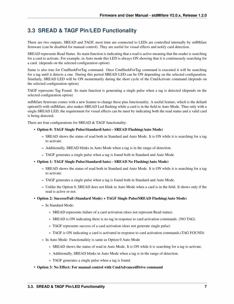
3.3 SREAD & TAGF Pin/LED Functionality
There are two outputs, SREAD and TAGF, most time are connected to LEDs are controlled internally by stdMifarefirmware (can be disabled for manual control). They are useful for visual effects and notify card detection.
SREAD represents Read Status. Its main function is indicating that a read is active meaning that the reader is searchingfor a card to activate. For example, in Auto mode this LED is always ON showing that it is continuously searching fora card. (depends on the selected configuration option)
Same is also true for CmdSeekForTag command. Once CmdSeekForTag command is executed it will be searchingfor a tag until it detects a one. During this period SREAD LED can be ON depending on the selected configuration.Similarly, SREAD LED will be ON momentarily during the short cycle of the CmdActivate command (depends onthe selected configuration option)
TAGF represents Tag Found. Its main function is generating a single pulse when a tag is detected (depends on theselected configuration option)
stdMifare firmware comes with a new feature to change these pins functionality. A useful feature, which is the defaultoption(0) with stdMifare, also makes SREAD Led flashing while a card is in the field in Auto Mode. Thus only with asingle SREAD LED, the requirement for visual effects can be meet by indicating both the read status and a valid cardis being detected.
There are four configurations for SREAD & TAGF functionality:
• Option 0: TAGF Single Pulse(Standard/Auto) - SREAD Flashing(Auto Mode)
– SREAD shows the status of read both in Standard and Auto Mode. It is ON while it is searching for a tagto activate.
– Additionally, SREAD blinks in Auto Mode when a tag is in the range of detection.
– TAGF generates a single pulse when a tag is found both in Standard and Auto Mode.
• Option 1: TAGF Single Pulse(Standard/Auto) - SREAD No Flashing(Auto Mode)
– SREAD shows the status of read both in Standard and Auto Mode. It is ON while it is searching for a tagto activate.
– TAGF generates a single pulse when a tag is found both in Standard and Auto Mode.
– Unlike the Option 0, SREAD does not blink in Auto Mode when a card is in the field. It shows only if theread is active or not.
• Option 2: Success/Fail (Standard Mode) + TAGF Single Pulse/SREAD Flashing(Auto Mode)
– In Standard Mode:
* SREAD represents failure of a card activation (does not represent Read status).
* SREAD is ON indicating there is no tag in response to card activation commands. (NO TAG)
* TAGF represents success of a card activation (does not generate single pulse)
* TAGF is ON indicating a card is activated in response to card activation commands.(TAG FOUND)
– In Auto Mode: Functionalitiy is same as Option 0 Auto Mode
* SREAD shows the status of read in Auto Mode. It is ON while it is searching for a tag to activate.
* Additionally, SREAD blinks in Auto Mode when a tag is in the range of detection.
* TAGF generates a single pulse when a tag is found.
• Option 3: No Effect: For manual control with CmdAdvancedDrive command
3.3. SREAD & TAGF Pin/LED Functionality 7
Firmware and User Manual - stdMifare V2.0.x, Release 1.2.0
– SREAD and TAGF control by internal firmware is disabled, and the control is left to user. Select this optionif you would like to drive SREAD and TAGF pins manually by the CmdAdvancedOutputDrive command.
3.4 OUT3 (BUZZER) Pin Functionality
OUT3, most time is connected to a buzzer (DC or AC), can be controlled internally by the stdMifare firmware or bythe CmdAdvancedOutputDrive command.
There are configuration options to generate a pulse (beep) on certain conditions i.e. on POR, Tag found etc.
stdMifare introduces, TypeB pinout connection (recommended for new designs), which comes with PWM buzzerdriving capability. PWM/AC Buzzer is more stable and generates better sound if it works beneath the antenna. IfPWM buzzer option is selected, OUT3 will be driven with around ~2730HZ, otherwise it will generate a DC pulse forin use with a DC buzzer.
Note:
• For different buzzer frequencies, customization is possible.
• CST-951AP Buzzer from CUI Inc. is generally used with the SonMicro readers and stdMifare PWM output iscompatible with this buzzer.
Note:
• A DC buzzer connected to PWM square wave may also generate sound. However, the sound quality may or notbe satisfactory. It is recommended to stick; buzzer and the driving type matches each other.
8 Chapter 3. FUNCTIONALITY & OPERATION MODES
Firmware and User Manual - stdMifare V2.0.x, Release 1.2.0
3.5 RS485 Operation
Note:
• For more information and details about the RS485 communication protocol, please also see the Mifare® Read-ers UART/I2C Communication Protocol – SPV1 document.
• Please also see target device’s hardware manual document for the electrical specifications, precautions and theproper connection diagram.
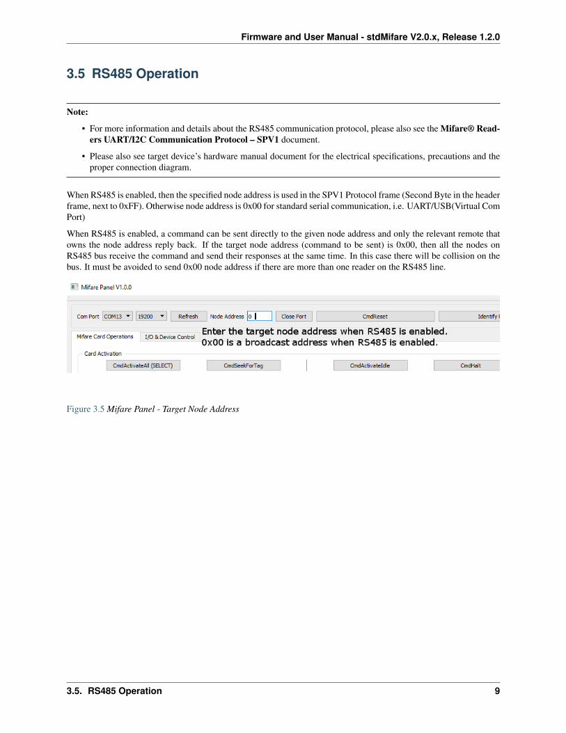
When RS485 is enabled, then the specified node address is used in the SPV1 Protocol frame (Second Byte in the headerframe, next to 0xFF). Otherwise node address is 0x00 for standard serial communication, i.e. UART/USB(Virtual ComPort)
When RS485 is enabled, a command can be sent directly to the given node address and only the relevant remote thatowns the node address reply back. If the target node address (command to be sent) is 0x00, then all the nodes onRS485 bus receive the command and send their responses at the same time. In this case there will be collision on thebus. It must be avoided to send 0x00 node address if there are more than one reader on the RS485 line.
Figure 3.5 Mifare Panel - Target Node Address
3.5. RS485 Operation 9
Firmware and User Manual - stdMifare V2.0.x, Release 1.2.0
Example Command (CmdActivateAll) - RS485 DISABLEDFF (00) 01 83 84If RS485 is not enabled, node address 0x00 is used.
Response:FF (00) 02 83 4E D3Expected response is sent with the 0x00 node address when the RS485 is disabled
Example Command (CmdActivateAll) - RS485 ENABLED - Target Node:0x00FF (00) 01 83 84If RS485 is enabled this command will be sent to the all nodes (0x00 acts as a broadcast address).However, if there are more than one reader then all the readers will reply back and there will be collision on theRS485 bus.
Response:FF (01) 02 83 4E D4Node 0x01 is replied back with No Tag Response. Assuming only one reader is found on the RS485 bus.
Example Command (CmdActivateAll) - RS485 ENABLED - Target Node:0x08FF (08) 01 83 8CCmdActivateAll command is sent to the 0x08 node. Only the reader who owns the 0x08 node address will reply back.
Response:FF (08) 02 83 4E DBNode 0x08 is replied back with No Tag Response.
3.5.1 RS485 BIDIRECTIONAL & POLLING MODES
There are two modes can be selected for the RS485 operation in Auto Mode.
Bidirectional mode is just as the standard communication, supports two-way communication, both sides can send dataanytime. For example; in Auto Mode, reader sends card UID as soon as it is detected without waiting a command fromthe master controller. Similarly, if SendFirmwareVersionOnStartup setting is enabled, the reader sends the firmwareversion information on Startup (POR) asynchronously. This mode may not be best option if there are more than onereader on the bus, and master wants to take the full control. (i.e. master wants to know readers are alive) There is alsoa possibility that more than one reader sends card UID at the same time that causes a collision on the bus and corrupteddata.
Polling mode is another option, can be used only in Auto mode, that aims to give the full control to the mastercontroller. In this mode, the reader never sends any data without master is asking for. A typical multi-device RS485application is generally queried by a master controller one by one periodically. If the number of the readers on the busincrease then the time for the next query cycle will be delayed. This may result in undetected cards or delayed cardreadings and undesired user experience. Polling mode prevents this situation to be happened. When a card is detected,it is not reported immediately, instead, it is kept in reader’s polling buffer temporarily for around 5 seconds. Mastercan query the reader with the CmdPollBuffer command to get the card UID from the buffer if available any. Becausethe master keeps sending CmdPollBuffer to the all readers, this mode also ensures the communication with the remotereaders are working healthy if there is no timeout event occur.
10 Chapter 3. FUNCTIONALITY & OPERATION MODES

Firmware and User Manual - stdMifare V2.0.x, Release 1.2.0
3.6 I2C Operation (Slave)
stdMifare firmware supports the I2C communication built-in and depends on the configuration; it comes enabled ornot. It can be enabled or disabled with the relevant configuration command or thru software tools i.e. Mifare Panel aswell.
I2C and UART share the same commands, only the frame structure is slightly different.
• For UART/I2C communication protocol details please see the Mifare® Readers UART/I2C CommunicationProtocol – SPV1 document.
• For hardware specifications please refer module/reader datasheet or hardware manual.
I2C is supported in standard mode only (command-response manner). Any Mifare card operations, or I/O control donewith the UART can be also done with the I2C interface, without any limitations, excluding the upgrade process.
3.6. I2C Operation (Slave) 11

Firmware and User Manual - stdMifare V2.0.x, Release 1.2.0
12 Chapter 3. FUNCTIONALITY & OPERATION MODES

CHAPTER
FOUR
DEVICE CONFIGURATION
Modules or readers can be configured with the provided command APIs or SDK, or with the provided software tools.Mifare Panel, is a cross-platform software tool, can be used to configure the readers.
Figure 4 Mifare Panel - Configuration Window for stdMifare and UM1.3R 1.1.4(previous firmware)
Note:
• It is also an option to upgrade the module/reader with supplied .xml upgrade file that holds the required config-uration built-in. Thus, no further configuration process is required.
13
Firmware and User Manual - stdMifare V2.0.x, Release 1.2.0
4.1 Ordering Configuration Code
stdMifare firmware version is integrated with variety of configurable features to meet different requirements withinthe same firmware. However, increase in number of features causes the complexity of the ordering. Thus, to managedifferent configurations easier and ordering the module and readers with the right configuration, Ordering Configu-ration Code system is introduced.
Attention: There are more than one template or default configurations depends on the module, or the reader type.For repeating orders, it is important to check the configuration code for persistence of the existing system and havetools (ability to connect the module/reader to the PC or linux with appropriate communication interface) to changethe configuration at your field in case it is needed.
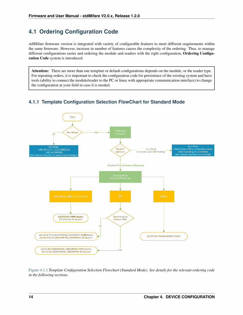
4.1.1 Template Configuration Selection FlowChart for Standard Mode
Figure 4.1.1 Template Configuration Selection Flowchart (Standard Mode). See details for the relevant ordering codein the following sections.
14 Chapter 4. DEVICE CONFIGURATION
Firmware and User Manual - stdMifare V2.0.x, Release 1.2.0
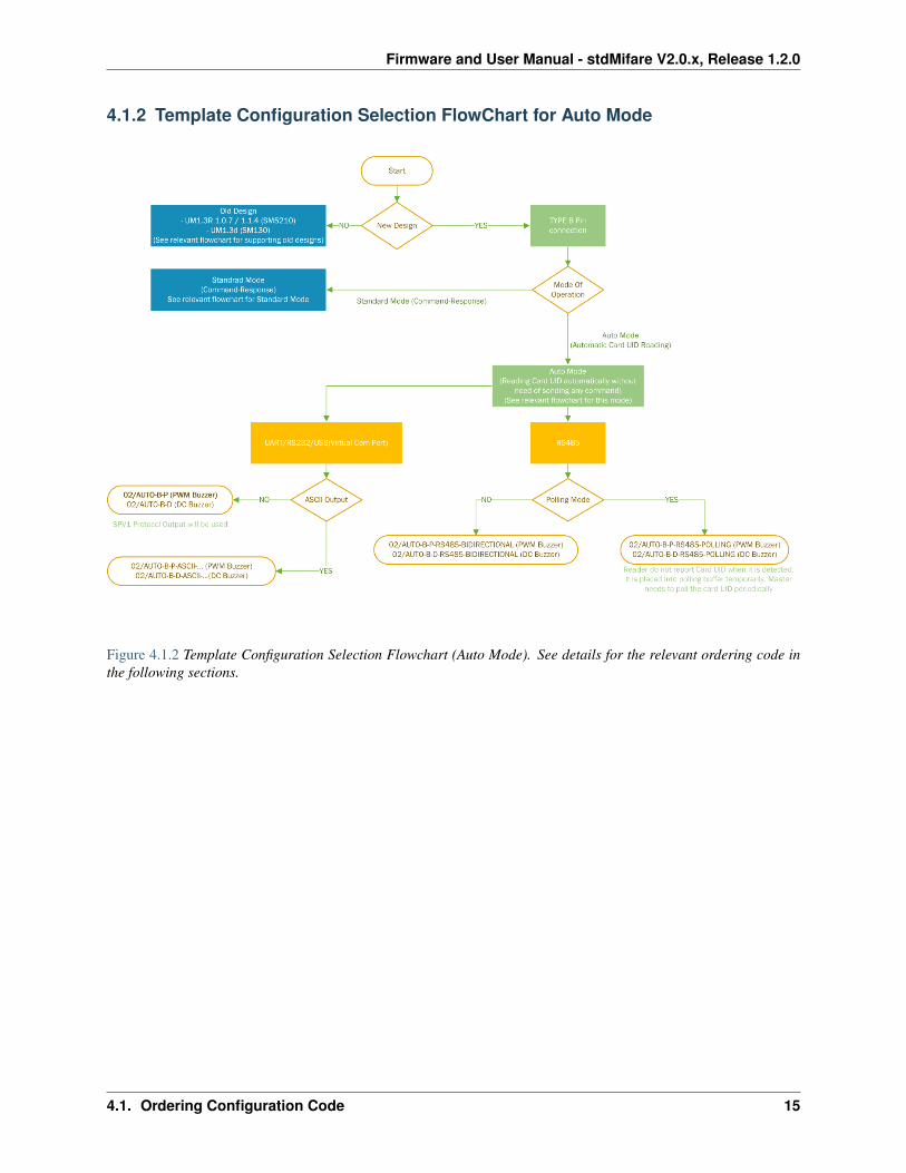
4.1.2 Template Configuration Selection FlowChart for Auto Mode
Figure 4.1.2 Template Configuration Selection Flowchart (Auto Mode). See details for the relevant ordering code inthe following sections.
4.1. Ordering Configuration Code 15

Firmware and User Manual - stdMifare V2.0.x, Release 1.2.0
4.1.3 Template Configuration Selection FlowChart for Backward Compatibility
Figure 4.1.3 Template Configuration Selection Flowchart (Backward Compatibility). See details for the relevant or-dering code in the following sections.
16 Chapter 4. DEVICE CONFIGURATION
Firmware and User Manual - stdMifare V2.0.x, Release 1.2.0
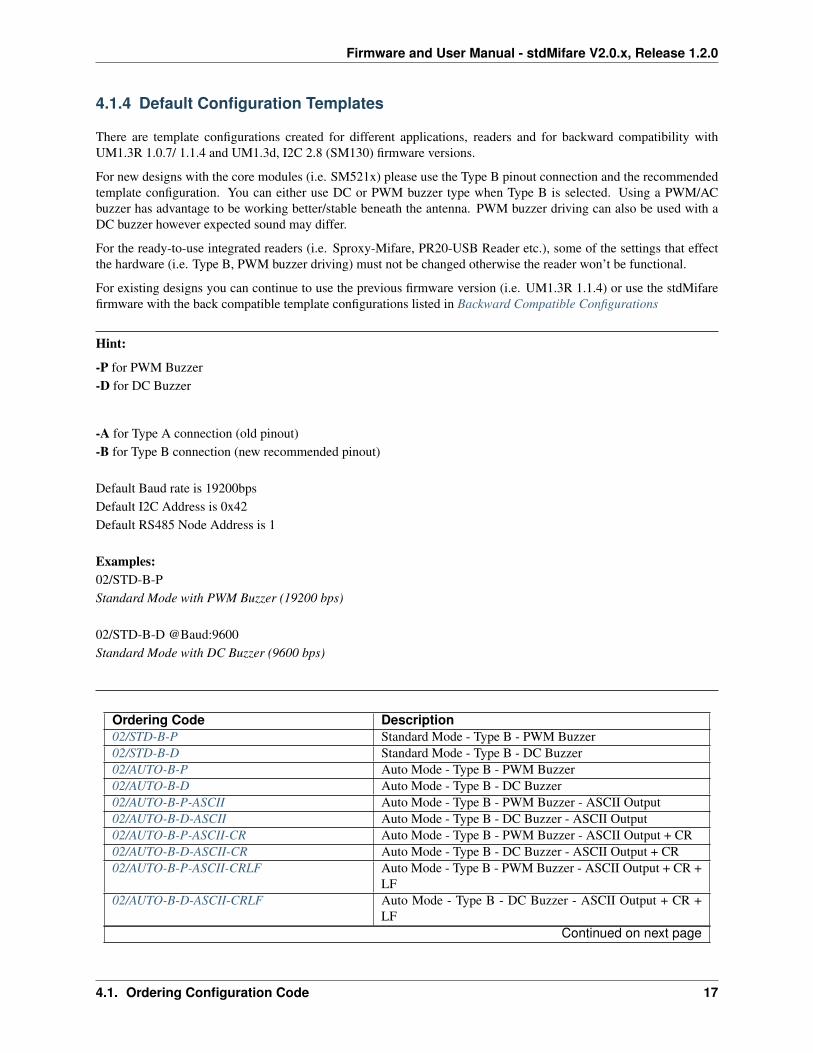
4.1.4 Default Configuration Templates
There are template configurations created for different applications, readers and for backward compatibility withUM1.3R 1.0.7/ 1.1.4 and UM1.3d, I2C 2.8 (SM130) firmware versions.
For new designs with the core modules (i.e. SM521x) please use the Type B pinout connection and the recommendedtemplate configuration. You can either use DC or PWM buzzer type when Type B is selected. Using a PWM/ACbuzzer has advantage to be working better/stable beneath the antenna. PWM buzzer driving can also be used with aDC buzzer however expected sound may differ.
For the ready-to-use integrated readers (i.e. Sproxy-Mifare, PR20-USB Reader etc.), some of the settings that effectthe hardware (i.e. Type B, PWM buzzer driving) must not be changed otherwise the reader won’t be functional.
For existing designs you can continue to use the previous firmware version (i.e. UM1.3R 1.1.4) or use the stdMifarefirmware with the back compatible template configurations listed in Backward Compatible Configurations
Hint:
-P for PWM Buzzer-D for DC Buzzer
-A for Type A connection (old pinout)-B for Type B connection (new recommended pinout)
Default Baud rate is 19200bpsDefault I2C Address is 0x42Default RS485 Node Address is 1
Examples:02/STD-B-PStandard Mode with PWM Buzzer (19200 bps)
02/STD-B-D @Baud:9600Standard Mode with DC Buzzer (9600 bps)
Ordering Code Description02/STD-B-P Standard Mode - Type B - PWM Buzzer02/STD-B-D Standard Mode - Type B - DC Buzzer02/AUTO-B-P Auto Mode - Type B - PWM Buzzer02/AUTO-B-D Auto Mode - Type B - DC Buzzer02/AUTO-B-P-ASCII Auto Mode - Type B - PWM Buzzer - ASCII Output02/AUTO-B-D-ASCII Auto Mode - Type B - DC Buzzer - ASCII Output02/AUTO-B-P-ASCII-CR Auto Mode - Type B - PWM Buzzer - ASCII Output + CR02/AUTO-B-D-ASCII-CR Auto Mode - Type B - DC Buzzer - ASCII Output + CR02/AUTO-B-P-ASCII-CRLF Auto Mode - Type B - PWM Buzzer - ASCII Output + CR +
LF02/AUTO-B-D-ASCII-CRLF Auto Mode - Type B - DC Buzzer - ASCII Output + CR +
LFContinued on next page
4.1. Ordering Configuration Code 17
Firmware and User Manual - stdMifare V2.0.x, Release 1.2.0
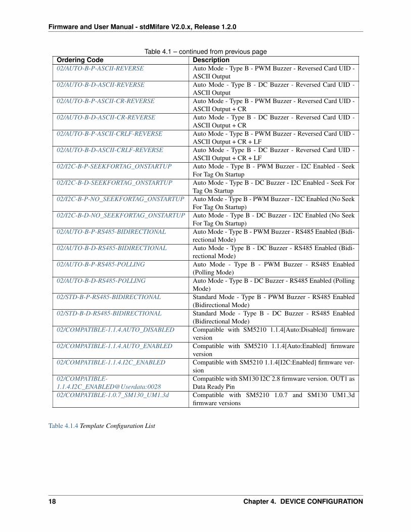
Table 4.1 – continued from previous pageOrdering Code Description02/AUTO-B-P-ASCII-REVERSE Auto Mode - Type B - PWM Buzzer - Reversed Card UID -
ASCII Output02/AUTO-B-D-ASCII-REVERSE Auto Mode - Type B - DC Buzzer - Reversed Card UID -
ASCII Output02/AUTO-B-P-ASCII-CR-REVERSE Auto Mode - Type B - PWM Buzzer - Reversed Card UID -
ASCII Output + CR02/AUTO-B-D-ASCII-CR-REVERSE Auto Mode - Type B - DC Buzzer - Reversed Card UID -
ASCII Output + CR02/AUTO-B-P-ASCII-CRLF-REVERSE Auto Mode - Type B - PWM Buzzer - Reversed Card UID -
ASCII Output + CR + LF02/AUTO-B-D-ASCII-CRLF-REVERSE Auto Mode - Type B - DC Buzzer - Reversed Card UID -
ASCII Output + CR + LF02/I2C-B-P-SEEKFORTAG_ONSTARTUP Auto Mode - Type B - PWM Buzzer - I2C Enabled - Seek
For Tag On Startup02/I2C-B-D-SEEKFORTAG_ONSTARTUP Auto Mode - Type B - DC Buzzer - I2C Enabled - Seek For
Tag On Startup02/I2C-B-P-NO_SEEKFORTAG_ONSTARTUP Auto Mode - Type B - PWM Buzzer - I2C Enabled (No Seek
For Tag On Startup)02/I2C-B-D-NO_SEEKFORTAG_ONSTARTUP Auto Mode - Type B - DC Buzzer - I2C Enabled (No Seek
For Tag On Startup)02/AUTO-B-P-RS485-BIDIRECTIONAL Auto Mode - Type B - PWM Buzzer - RS485 Enabled (Bidi-
rectional Mode)02/AUTO-B-D-RS485-BIDIRECTIONAL Auto Mode - Type B - DC Buzzer - RS485 Enabled (Bidi-
rectional Mode)02/AUTO-B-P-RS485-POLLING Auto Mode - Type B - PWM Buzzer - RS485 Enabled
(Polling Mode)02/AUTO-B-D-RS485-POLLING Auto Mode - Type B - DC Buzzer - RS485 Enabled (Polling
Mode)02/STD-B-P-RS485-BIDIRECTIONAL Standard Mode - Type B - PWM Buzzer - RS485 Enabled
(Bidirectional Mode)02/STD-B-D-RS485-BIDIRECTIONAL Standard Mode - Type B - DC Buzzer - RS485 Enabled
(Bidirectional Mode)02/COMPATIBLE-1.1.4.AUTO_DISABLED Compatible with SM5210 1.1.4[Auto:Disabled] firmware
version02/COMPATIBLE-1.1.4.AUTO_ENABLED Compatible with SM5210 1.1.4[Auto:Enabled] firmware
version02/COMPATIBLE-1.1.4.I2C_ENABLED Compatible with SM5210 1.1.4[I2C:Enabled] firmware ver-
sion02/COMPATIBLE-1.1.4.I2C_ENABLED@Userdata:0028
Compatible with SM130 I2C 2.8 firmware version. OUT1 asData Ready Pin
02/COMPATIBLE-1.0.7_SM130_UM1.3d Compatible with SM5210 1.0.7 and SM130 UM1.3dfirmware versions
Table 4.1.4 Template Configuration List
18 Chapter 4. DEVICE CONFIGURATION
Firmware and User Manual - stdMifare V2.0.x, Release 1.2.0
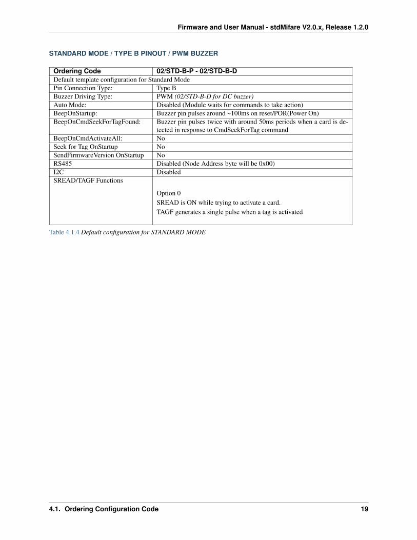
STANDARD MODE / TYPE B PINOUT / PWM BUZZER
Ordering Code 02/STD-B-P - 02/STD-B-DDefault template configuration for Standard ModePin Connection Type: Type BBuzzer Driving Type: PWM (02/STD-B-D for DC buzzer)Auto Mode: Disabled (Module waits for commands to take action)BeepOnStartup: Buzzer pin pulses around ~100ms on reset/POR(Power On)BeepOnCmdSeekForTagFound: Buzzer pin pulses twice with around 50ms periods when a card is de-
tected in response to CmdSeekForTag commandBeepOnCmdActivateAll: NoSeek for Tag OnStartup NoSendFirmwareVersion OnStartup NoRS485 Disabled (Node Address byte will be 0x00)I2C DisabledSREAD/TAGF Functions
Option 0SREAD is ON while trying to activate a card.TAGF generates a single pulse when a tag is activated
Table 4.1.4 Default configuration for STANDARD MODE
4.1. Ordering Configuration Code 19

Firmware and User Manual - stdMifare V2.0.x, Release 1.2.0
AUTO MODE / TYPE B PINOUT / PWM BUZZER
Ordering Code 02/AUTO-B-P - 02/AUTO-B-DDefault template configuration for Auto ModePin Connection Type: Type BBuzzer Driving Type: PWM (02/AUTO-B-D for DC buzzer)Auto Mode: Enabled (Reader activates a card whenever it is placed near the an-
tenna.)Auto Mode - BeepOnTagFound: Buzzer pin pulses twice with around 50ms periods when a a card is
detected in Auto ModeAuto Mode - Serial Output: Spv1 protocol Ex: 0xFF Node Length Cmd Data CS(Checksum)BeepOnStartup: Buzzer pin pulses around ~100ms on reset/POR(Power On)BeepOnCmdActivateAll: NoSendFirmwareVersion OnStartup NoRS485 Disabled (Node Address byte will be 0x00)I2C DisabledSREAD/TAGF Functions
0SREAD is ON when reader is searching for a cardSREAD blinks(flashes) while a card is in the fieldTAGF generates a single pulse when a tag is activated
A single led connected to SREAD pin can be used with thisconfiguration for visual effects indicating both cardread status and card detected status
SeekForTag command cannot be used in Auto Mode
Table 4.1.4 Default configuration for AUTO MODE
20 Chapter 4. DEVICE CONFIGURATION
Firmware and User Manual - stdMifare V2.0.x, Release 1.2.0
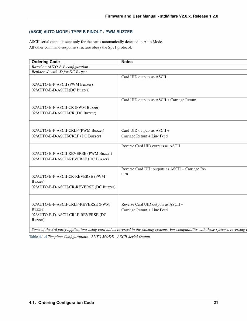
(ASCII) AUTO MODE / TYPE B PINOUT / PWM BUZZER
ASCII serial output is sent only for the cards automatically detected in Auto Mode.All other command-response structure obeys the Spv1 protocol.
Ordering Code NotesBased on AUTO-B-P configuration.Replace -P with -D for DC Buzzer
02/AUTO-B-P-ASCII (PWM Buzzer)02/AUTO-B-D-ASCII (DC Buzzer)
Card UID outputs as ASCII
02/AUTO-B-P-ASCII-CR (PWM Buzzer)02/AUTO-B-D-ASCII-CR (DC Buzzer)
Card UID outputs as ASCII + Carriage Return
02/AUTO-B-P-ASCII-CRLF (PWM Buzzer)02/AUTO-B-D-ASCII-CRLF (DC Buzzer)
Card UID outputs as ASCII +Carriage Return + Line Feed
02/AUTO-B-P-ASCII-REVERSE (PWM Buzzer)02/AUTO-B-D-ASCII-REVERSE (DC Buzzer)
Reverse Card UID outputs as ASCII
02/AUTO-B-P-ASCII-CR-REVERSE (PWMBuzzer)02/AUTO-B-D-ASCII-CR-REVERSE (DC Buzzer)
Reverse Card UID outputs as ASCII + Carriage Re-turn
02/AUTO-B-P-ASCII-CRLF-REVERSE (PWMBuzzer)02/AUTO-B-D-ASCII-CRLF-REVERSE (DCBuzzer)
Reverse Card UID outputs as ASCII +Carriage Return + Line Feed
Some of the 3rd party applications using card uid as reversed in the existing systems. For compatibility with these systems, reversing card uid is supported.
Table 4.1.4 Template Configurations - AUTO MODE - ASCII Serial Output
4.1. Ordering Configuration Code 21
Firmware and User Manual - stdMifare V2.0.x, Release 1.2.0
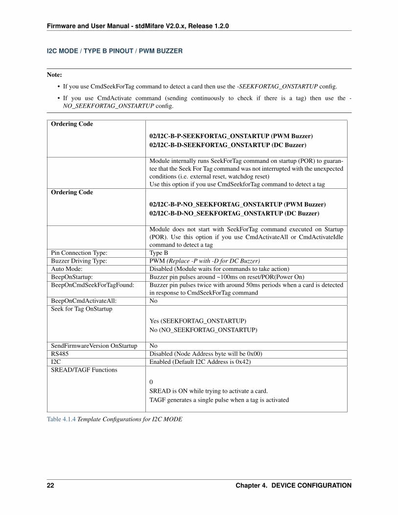
I2C MODE / TYPE B PINOUT / PWM BUZZER
Note:
• If you use CmdSeekForTag command to detect a card then use the -SEEKFORTAG_ONSTARTUP config.
• If you use CmdActivate command (sending continuously to check if there is a tag) then use the -NO_SEEKFORTAG_ONSTARTUP config.
Ordering Code
02/I2C-B-P-SEEKFORTAG_ONSTARTUP (PWM Buzzer)02/I2C-B-D-SEEKFORTAG_ONSTARTUP (DC Buzzer)
Module internally runs SeekForTag command on startup (POR) to guaran-tee that the Seek For Tag command was not interrupted with the unexpectedconditions (i.e. external reset, watchdog reset)Use this option if you use CmdSeekforTag command to detect a tag
Ordering Code
02/I2C-B-P-NO_SEEKFORTAG_ONSTARTUP (PWM Buzzer)02/I2C-B-D-NO_SEEKFORTAG_ONSTARTUP (DC Buzzer)
Module does not start with SeekForTag command executed on Startup(POR). Use this option if you use CmdActivateAll or CmdActivateIdlecommand to detect a tag
Pin Connection Type: Type BBuzzer Driving Type: PWM (Replace -P with -D for DC Buzzer)Auto Mode: Disabled (Module waits for commands to take action)BeepOnStartup: Buzzer pin pulses around ~100ms on reset/POR(Power On)BeepOnCmdSeekForTagFound: Buzzer pin pulses twice with around 50ms periods when a card is detected
in response to CmdSeekForTag commandBeepOnCmdActivateAll: NoSeek for Tag OnStartup
Yes (SEEKFORTAG_ONSTARTUP)No (NO_SEEKFORTAG_ONSTARTUP)
SendFirmwareVersion OnStartup NoRS485 Disabled (Node Address byte will be 0x00)I2C Enabled (Default I2C Address is 0x42)SREAD/TAGF Functions
0SREAD is ON while trying to activate a card.TAGF generates a single pulse when a tag is activated
Table 4.1.4 Template Configurations for I2C MODE
22 Chapter 4. DEVICE CONFIGURATION
Firmware and User Manual - stdMifare V2.0.x, Release 1.2.0
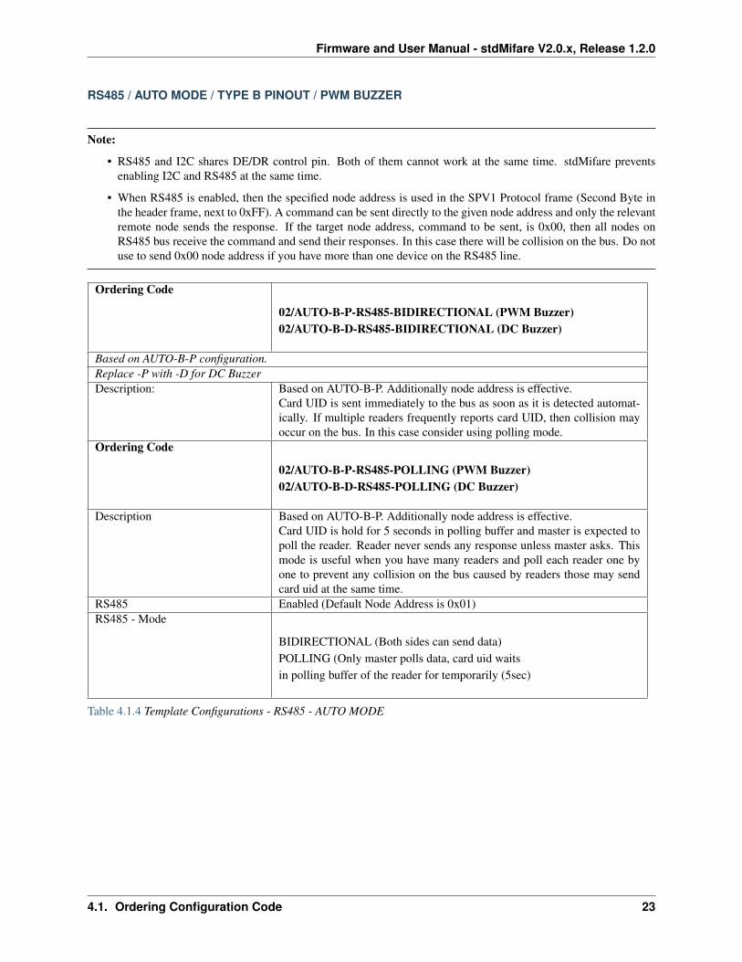
RS485 / AUTO MODE / TYPE B PINOUT / PWM BUZZER
Note:
• RS485 and I2C shares DE/DR control pin. Both of them cannot work at the same time. stdMifare preventsenabling I2C and RS485 at the same time.
• When RS485 is enabled, then the specified node address is used in the SPV1 Protocol frame (Second Byte inthe header frame, next to 0xFF). A command can be sent directly to the given node address and only the relevantremote node sends the response. If the target node address, command to be sent, is 0x00, then all nodes onRS485 bus receive the command and send their responses. In this case there will be collision on the bus. Do notuse to send 0x00 node address if you have more than one device on the RS485 line.
Ordering Code
02/AUTO-B-P-RS485-BIDIRECTIONAL (PWM Buzzer)02/AUTO-B-D-RS485-BIDIRECTIONAL (DC Buzzer)
Based on AUTO-B-P configuration.Replace -P with -D for DC BuzzerDescription: Based on AUTO-B-P. Additionally node address is effective.
Card UID is sent immediately to the bus as soon as it is detected automat-ically. If multiple readers frequently reports card UID, then collision mayoccur on the bus. In this case consider using polling mode.
Ordering Code
02/AUTO-B-P-RS485-POLLING (PWM Buzzer)02/AUTO-B-D-RS485-POLLING (DC Buzzer)
Description Based on AUTO-B-P. Additionally node address is effective.Card UID is hold for 5 seconds in polling buffer and master is expected topoll the reader. Reader never sends any response unless master asks. Thismode is useful when you have many readers and poll each reader one byone to prevent any collision on the bus caused by readers those may sendcard uid at the same time.
RS485 Enabled (Default Node Address is 0x01)RS485 - Mode
BIDIRECTIONAL (Both sides can send data)POLLING (Only master polls data, card uid waitsin polling buffer of the reader for temporarily (5sec)
Table 4.1.4 Template Configurations - RS485 - AUTO MODE
4.1. Ordering Configuration Code 23
Firmware and User Manual - stdMifare V2.0.x, Release 1.2.0
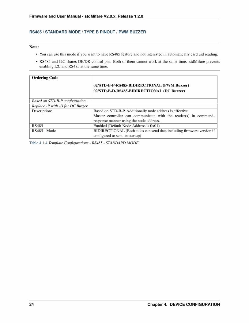
RS485 / STANDARD MODE / TYPE B PINOUT / PWM BUZZER
Note:
• You can use this mode if you want to have RS485 feature and not interested in automatically card uid reading.
• RS485 and I2C shares DE/DR control pin. Both of them cannot work at the same time. stdMifare preventsenabling I2C and RS485 at the same time.
Ordering Code
02/STD-B-P-RS485-BIDIRECTIONAL (PWM Buzzer)02/STD-B-D-RS485-BIDIRECTIONAL (DC Buzzer)
Based on STD-B-P configuration.Replace -P with -D for DC BuzzerDescription: Based on STD-B-P. Additionally node address is effective.
Master controller can communicate with the reader(s) in command-response manner using the node address.
RS485 Enabled (Default Node Address is 0x01)RS485 - Mode BIDIRECTIONAL (Both sides can send data including firmware version if
configured to sent on startup)
Table 4.1.4 Template Configurations - RS485 - STANDARD MODE
24 Chapter 4. DEVICE CONFIGURATION
Firmware and User Manual - stdMifare V2.0.x, Release 1.2.0
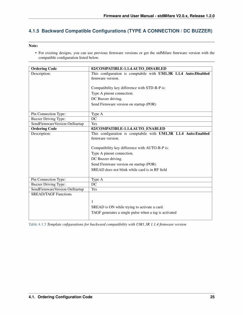
4.1.5 Backward Compatible Configurations (TYPE A CONNECTION / DC BUZZER)
Note:
• For existing designs, you can use previous firmware versions or get the stdMifare fimrware version with thecompatible configuration listed below.
Ordering Code 02/COMPATIBLE-1.1.4.AUTO_DISABLEDDescription: This configuration is comptabile with UM1.3R 1.1.4 Auto:Disabled
firmware version.
Compatibility key difference with STD-B-P is:Type A pinout connection.DC Buzzer driving.Send Firmware version on startup (POR)
Pin Connection Type: Type ABuzzer Driving Type: DCSendFirmwareVersion OnStartup YesOrdering Code 02/COMPATIBLE-1.1.4.AUTO_ENABLEDDescription: This configuration is comptabile with UM1.3R 1.1.4 Auto:Enabled
firmware version.
Compatibility key difference with AUTO-B-P is:Type A pinout connection.DC Buzzer driving.Send Firmware version on startup (POR)SREAD does not blink while card is in RF field
Pin Connection Type: Type ABuzzer Driving Type: DCSendFirmwareVersion OnStartup YesSREAD/TAGF Functions
1SREAD is ON while trying to activate a card.TAGF generates a single pulse when a tag is activated
Table 4.1.5 Template cnfigurations for backward compatibility with UM1.3R 1.1.4 firmware version
4.1. Ordering Configuration Code 25
Firmware and User Manual - stdMifare V2.0.x, Release 1.2.0
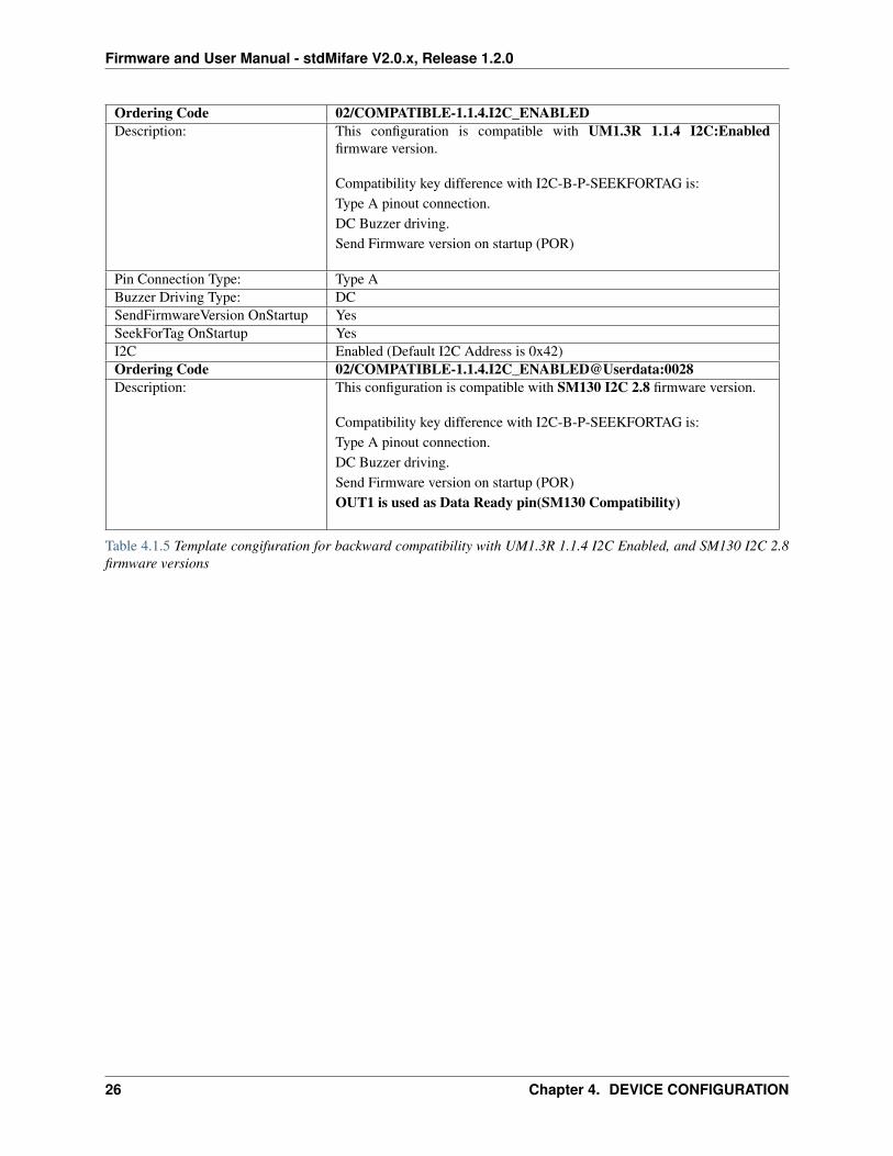
Ordering Code 02/COMPATIBLE-1.1.4.I2C_ENABLEDDescription: This configuration is compatible with UM1.3R 1.1.4 I2C:Enabled
firmware version.
Compatibility key difference with I2C-B-P-SEEKFORTAG is:Type A pinout connection.DC Buzzer driving.Send Firmware version on startup (POR)
Pin Connection Type: Type ABuzzer Driving Type: DCSendFirmwareVersion OnStartup YesSeekForTag OnStartup YesI2C Enabled (Default I2C Address is 0x42)Ordering Code 02/COMPATIBLE-1.1.4.I2C_ENABLED@Userdata:0028Description: This configuration is compatible with SM130 I2C 2.8 firmware version.
Compatibility key difference with I2C-B-P-SEEKFORTAG is:Type A pinout connection.DC Buzzer driving.Send Firmware version on startup (POR)OUT1 is used as Data Ready pin(SM130 Compatibility)
Table 4.1.5 Template congifuration for backward compatibility with UM1.3R 1.1.4 I2C Enabled, and SM130 I2C 2.8firmware versions
26 Chapter 4. DEVICE CONFIGURATION
Firmware and User Manual - stdMifare V2.0.x, Release 1.2.0
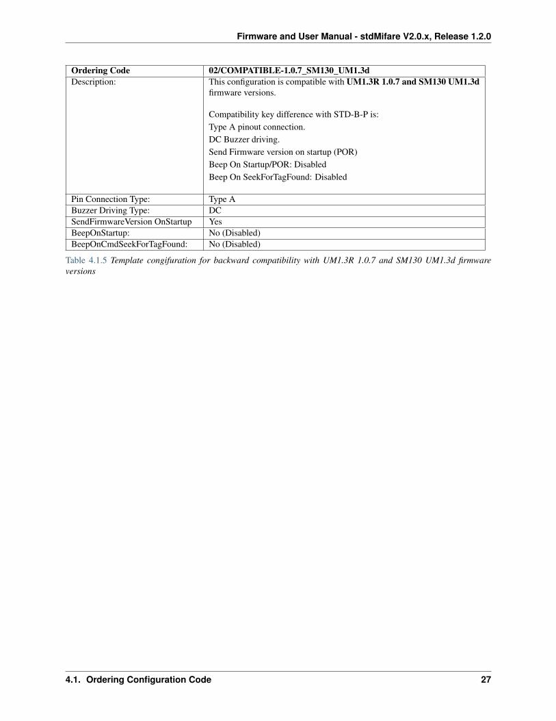
Ordering Code 02/COMPATIBLE-1.0.7_SM130_UM1.3dDescription: This configuration is compatible with UM1.3R 1.0.7 and SM130 UM1.3d
firmware versions.
Compatibility key difference with STD-B-P is:Type A pinout connection.DC Buzzer driving.Send Firmware version on startup (POR)Beep On Startup/POR: DisabledBeep On SeekForTagFound: Disabled
Pin Connection Type: Type ABuzzer Driving Type: DCSendFirmwareVersion OnStartup YesBeepOnStartup: No (Disabled)BeepOnCmdSeekForTagFound: No (Disabled)
Table 4.1.5 Template congifuration for backward compatibility with UM1.3R 1.0.7 and SM130 UM1.3d firmwareversions
4.1. Ordering Configuration Code 27
Firmware and User Manual - stdMifare V2.0.x, Release 1.2.0
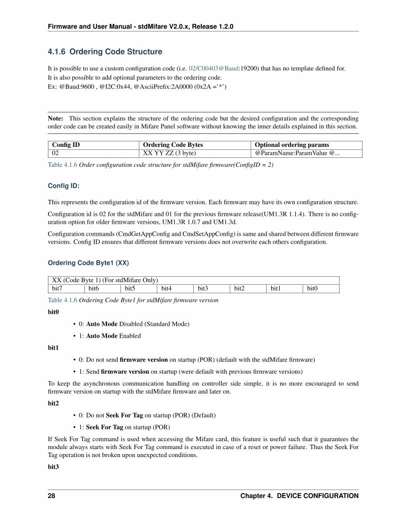
4.1.6 Ordering Code Structure
It is possible to use a custom configuration code (i.e. 02/C00403@Baud:19200) that has no template defined for.It is also possible to add optional parameters to the ordering code.Ex: @Baud:9600 , @I2C:0x44, @AsciiPrefix:2A0000 (0x2A =’*’)
Note: This section explains the structure of the ordering code but the desired configuration and the correspondingorder code can be created easily in Mifare Panel software without knowing the inner details explained in this section.
Config ID Ordering Code Bytes Optional ordering params02 XX YY ZZ (3 byte) @ParamName:ParamValue @...
Table 4.1.6 Order configuration code structure for stdMifare firmware(ConfigID = 2)
Config ID:
This represents the configuration id of the firmware version. Each firmware may have its own configuration structure.
Configuration id is 02 for the stdMifare and 01 for the previous firmware release(UM1.3R 1.1.4). There is no config-uration option for older firmware versions, UM1.3R 1.0.7 and UM1.3d.
Configuration commands (CmdGetAppConfig and CmdSetAppConfig) is same and shared between different firmwareversions. Config ID ensures that different firmware versions does not overwrite each others configuration.
Ordering Code Byte1 (XX)
XX (Code Byte 1) (For stdMifare Only)bit7 bit6 bit5 bit4 bit3 bit2 bit1 bit0
Table 4.1.6 Ordering Code Byte1 for stdMifare firmware version
bit0
• 0: Auto Mode Disabled (Standard Mode)
• 1: Auto Mode Enabled
bit1
• 0: Do not send firmware version on startup (POR) (default with the stdMifare firmware)
• 1: Send firmware version on startup (were default with previous firmware versions)
To keep the asynchronous communication handling on controller side simple, it is no more encouraged to sendfirmware version on startup with the stdMifare firmware and later on.
bit2
• 0: Do not Seek For Tag on startup (POR) (Default)
• 1: Seek For Tag on startup (POR)
If Seek For Tag command is used when accessing the Mifare card, this feature is useful such that it guarantees themodule always starts with Seek For Tag command is executed in case of a reset or power failure. Thus the Seek ForTag operation is not broken upon unexpected conditions.
bit3
28 Chapter 4. DEVICE CONFIGURATION
Firmware and User Manual - stdMifare V2.0.x, Release 1.2.0
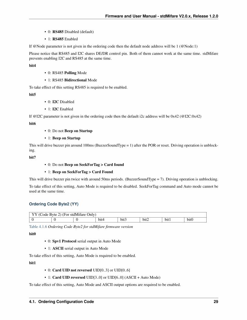
• 0: RS485 Disabled (default)
• 1: RS485 Enabled
If @Node parameter is not given in the ordering code then the default node address will be 1 (@Node:1)
Please notice that RS485 and I2C shares DE/DR control pin. Both of them cannot work at the same time. stdMifareprevents enabling I2C and RS485 at the same time.
bit4
• 0: RS485 Polling Mode
• 1: RS485 Bidirectional Mode
To take effect of this setting RS485 is required to be enabled.
bit5
• 0: I2C Disabled
• 1: I2C Enabled
If @I2C parameter is not given in the ordering code then the default i2c address will be 0x42 (@I2C:0x42)
bit6
• 0: Do not Beep on Startup
• 1: Beep on Startup
This will drive buzzer pin around 100ms (BuzzerSoundType = 1) after the POR or reset. Driving operation is unblock-ing.
bit7
• 0: Do not Beep on SeekForTag > Card found
• 1: Beep on SeekForTag > Card Found
This will drive buzzer pin twice with around 50ms periods. (BuzzerSoundType = 7). Driving operation is unblocking.
To take effect of this setting, Auto Mode is required to be disabled. SeekForTag command and Auto mode cannot beused at the same time.
Ordering Code Byte2 (YY)
YY (Code Byte 2) (For stdMifare Only)0 0 0 bit4 bit3 bit2 bit1 bit0
Table 4.1.6 Ordering Code Byte2 for stdMifare firmware version
bit0
• 0: Spv1 Protocol serial output in Auto Mode
• 1: ASCII serial output in Auto Mode
To take effect of this setting, Auto Mode is required to be enabled.
bit1
• 0: Card UID not reversed UID[0..3] or UID[0..6]
• 1: Card UID reversed UID[3..0] or UID[6..0] (ASCII + Auto Mode)
To take effect of this setting, Auto Mode and ASCII output options are required to be enabled.
4.1. Ordering Configuration Code 29
Firmware and User Manual - stdMifare V2.0.x, Release 1.2.0
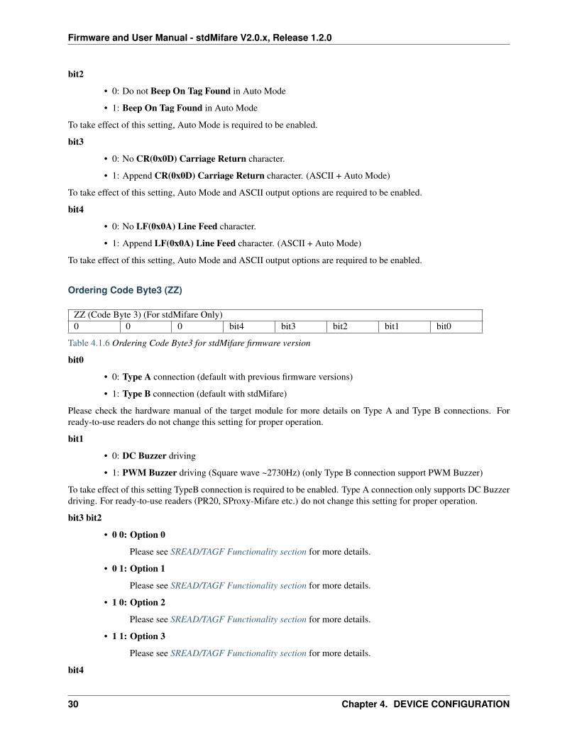
bit2
• 0: Do not Beep On Tag Found in Auto Mode
• 1: Beep On Tag Found in Auto Mode
To take effect of this setting, Auto Mode is required to be enabled.
bit3
• 0: No CR(0x0D) Carriage Return character.
• 1: Append CR(0x0D) Carriage Return character. (ASCII + Auto Mode)
To take effect of this setting, Auto Mode and ASCII output options are required to be enabled.
bit4
• 0: No LF(0x0A) Line Feed character.
• 1: Append LF(0x0A) Line Feed character. (ASCII + Auto Mode)
To take effect of this setting, Auto Mode and ASCII output options are required to be enabled.
Ordering Code Byte3 (ZZ)
ZZ (Code Byte 3) (For stdMifare Only)0 0 0 bit4 bit3 bit2 bit1 bit0
Table 4.1.6 Ordering Code Byte3 for stdMifare firmware version
bit0
• 0: Type A connection (default with previous firmware versions)
• 1: Type B connection (default with stdMifare)
Please check the hardware manual of the target module for more details on Type A and Type B connections. Forready-to-use readers do not change this setting for proper operation.
bit1
• 0: DC Buzzer driving
• 1: PWM Buzzer driving (Square wave ~2730Hz) (only Type B connection support PWM Buzzer)
To take effect of this setting TypeB connection is required to be enabled. Type A connection only supports DC Buzzerdriving. For ready-to-use readers (PR20, SProxy-Mifare etc.) do not change this setting for proper operation.
bit3 bit2
• 0 0: Option 0
Please see SREAD/TAGF Functionality section for more details.
• 0 1: Option 1
Please see SREAD/TAGF Functionality section for more details.
• 1 0: Option 2
Please see SREAD/TAGF Functionality section for more details.
• 1 1: Option 3
Please see SREAD/TAGF Functionality section for more details.
bit4
30 Chapter 4. DEVICE CONFIGURATION
Firmware and User Manual - stdMifare V2.0.x, Release 1.2.0
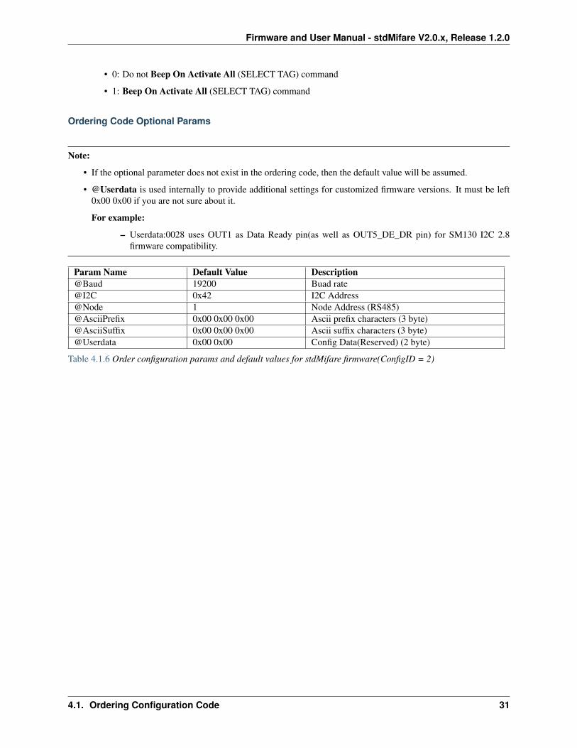
• 0: Do not Beep On Activate All (SELECT TAG) command
• 1: Beep On Activate All (SELECT TAG) command
Ordering Code Optional Params
Note:
• If the optional parameter does not exist in the ordering code, then the default value will be assumed.
• @Userdata is used internally to provide additional settings for customized firmware versions. It must be left0x00 0x00 if you are not sure about it.
For example:
– Userdata:0028 uses OUT1 as Data Ready pin(as well as OUT5_DE_DR pin) for SM130 I2C 2.8firmware compatibility.
Param Name Default Value Description@Baud 19200 Buad rate@I2C 0x42 I2C Address@Node 1 Node Address (RS485)@AsciiPrefix 0x00 0x00 0x00 Ascii prefix characters (3 byte)@AsciiSuffix 0x00 0x00 0x00 Ascii suffix characters (3 byte)@Userdata 0x00 0x00 Config Data(Reserved) (2 byte)
Table 4.1.6 Order configuration params and default values for stdMifare firmware(ConfigID = 2)
4.1. Ordering Configuration Code 31

Firmware and User Manual - stdMifare V2.0.x, Release 1.2.0
32 Chapter 4. DEVICE CONFIGURATION
CHAPTER
FIVE
STDMIFARE V2.0.X COMMANDS
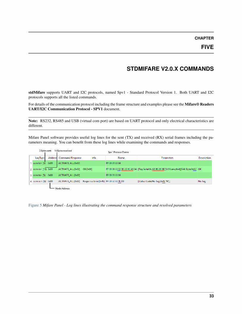
stdMifare supports UART and I2C protocols, named Spv1 - Standard Protocol Version 1. Both UART and I2Cprotocols supports all the listed commands.
For details of the communication protocol including the frame structure and examples please see the Mifare® ReadersUART/I2C Communication Protocol - SPV1 document.
Note: RS232, RS485 and USB (virtual com port) are based on UART protocol and only electrical characteristics aredifferent.
Mifare Panel software provides useful log lines for the sent (TX) and received (RX) serial frames including the pa-rameters meaning. You can benefit from these log lines while examining the commands and responses.
Figure 5 Mifare Panel - Log lines illustrating the command response structure and resolved parameters
33
Firmware and User Manual - stdMifare V2.0.x, Release 1.2.0
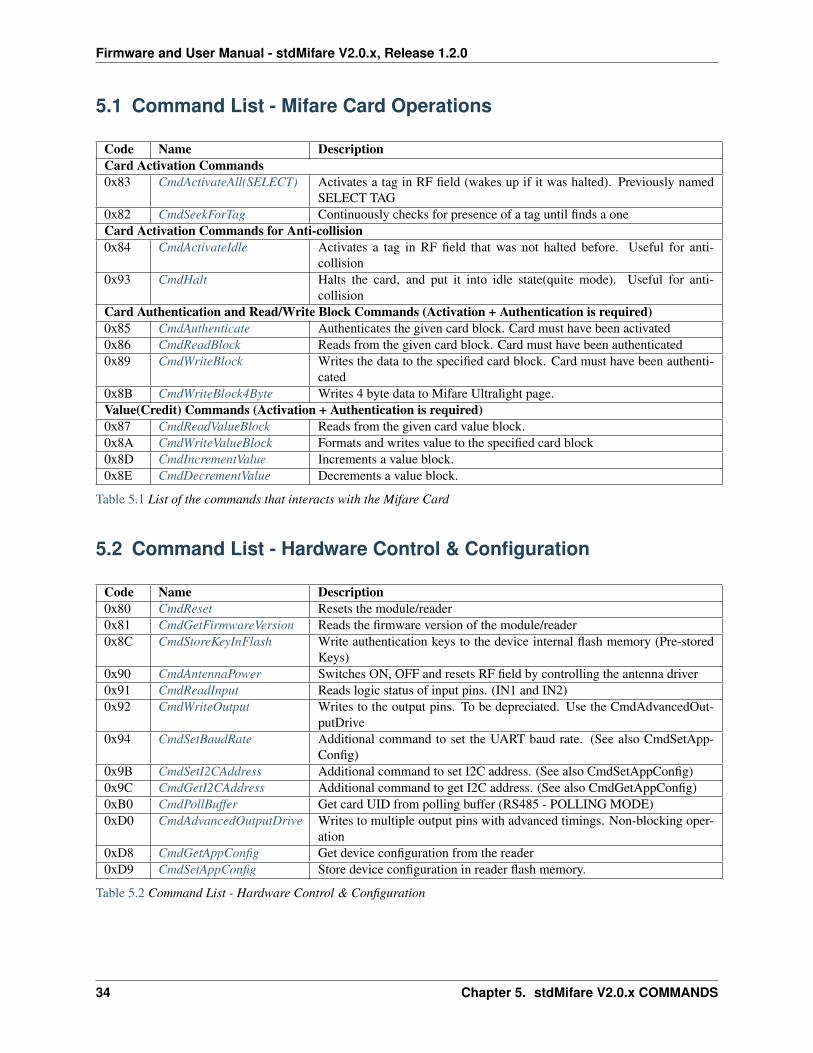
5.1 Command List - Mifare Card Operations
Code Name DescriptionCard Activation Commands0x83 CmdActivateAll(SELECT) Activates a tag in RF field (wakes up if it was halted). Previously named
SELECT TAG0x82 CmdSeekForTag Continuously checks for presence of a tag until finds a oneCard Activation Commands for Anti-collision0x84 CmdActivateIdle Activates a tag in RF field that was not halted before. Useful for anti-
collision0x93 CmdHalt Halts the card, and put it into idle state(quite mode). Useful for anti-
collisionCard Authentication and Read/Write Block Commands (Activation + Authentication is required)0x85 CmdAuthenticate Authenticates the given card block. Card must have been activated0x86 CmdReadBlock Reads from the given card block. Card must have been authenticated0x89 CmdWriteBlock Writes the data to the specified card block. Card must have been authenti-
cated0x8B CmdWriteBlock4Byte Writes 4 byte data to Mifare Ultralight page.Value(Credit) Commands (Activation + Authentication is required)0x87 CmdReadValueBlock Reads from the given card value block.0x8A CmdWriteValueBlock Formats and writes value to the specified card block0x8D CmdIncrementValue Increments a value block.0x8E CmdDecrementValue Decrements a value block.
Table 5.1 List of the commands that interacts with the Mifare Card
5.2 Command List - Hardware Control & Configuration
Code Name Description0x80 CmdReset Resets the module/reader0x81 CmdGetFirmwareVersion Reads the firmware version of the module/reader0x8C CmdStoreKeyInFlash Write authentication keys to the device internal flash memory (Pre-stored
Keys)0x90 CmdAntennaPower Switches ON, OFF and resets RF field by controlling the antenna driver0x91 CmdReadInput Reads logic status of input pins. (IN1 and IN2)0x92 CmdWriteOutput Writes to the output pins. To be depreciated. Use the CmdAdvancedOut-
putDrive0x94 CmdSetBaudRate Additional command to set the UART baud rate. (See also CmdSetApp-
Config)0x9B CmdSetI2CAddress Additional command to set I2C address. (See also CmdSetAppConfig)0x9C CmdGetI2CAddress Additional command to get I2C address. (See also CmdGetAppConfig)0xB0 CmdPollBuffer Get card UID from polling buffer (RS485 - POLLING MODE)0xD0 CmdAdvancedOutputDrive Writes to multiple output pins with advanced timings. Non-blocking oper-
ation0xD8 CmdGetAppConfig Get device configuration from the reader0xD9 CmdSetAppConfig Store device configuration in reader flash memory.
Table 5.2 Command List - Hardware Control & Configuration
34 Chapter 5. stdMifare V2.0.x COMMANDS
Firmware and User Manual - stdMifare V2.0.x, Release 1.2.0
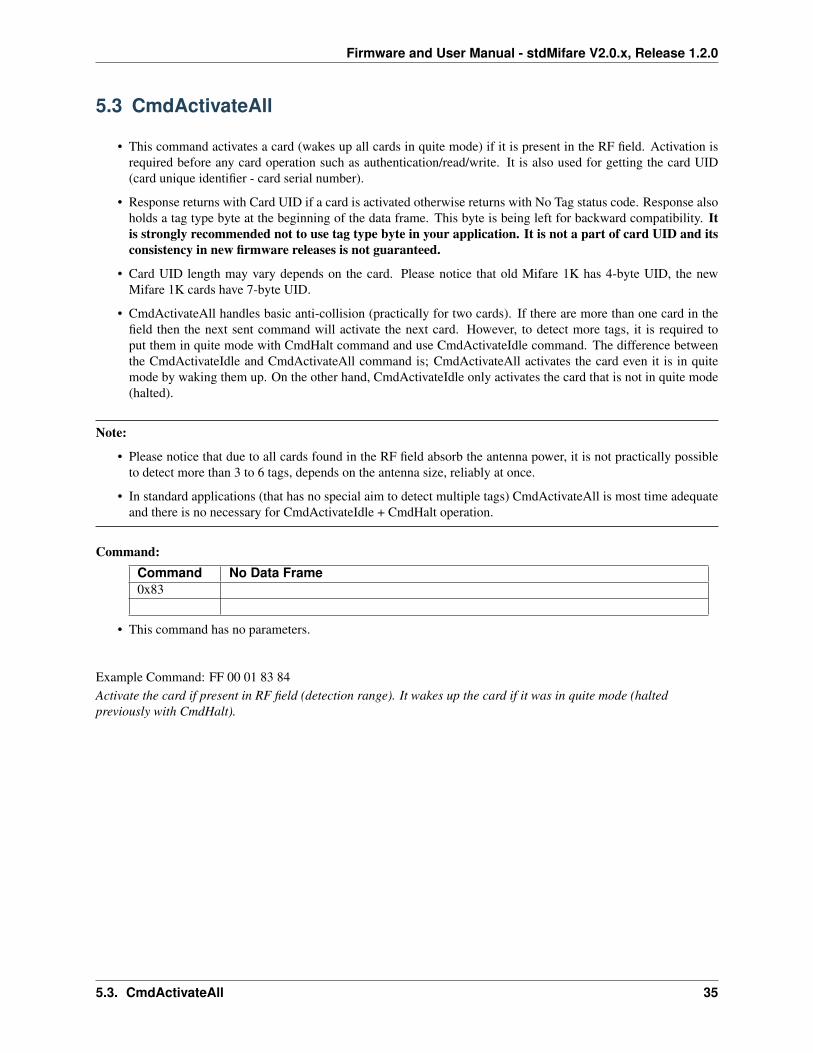
5.3 CmdActivateAll
• This command activates a card (wakes up all cards in quite mode) if it is present in the RF field. Activation isrequired before any card operation such as authentication/read/write. It is also used for getting the card UID(card unique identifier - card serial number).
• Response returns with Card UID if a card is activated otherwise returns with No Tag status code. Response alsoholds a tag type byte at the beginning of the data frame. This byte is being left for backward compatibility. Itis strongly recommended not to use tag type byte in your application. It is not a part of card UID and itsconsistency in new firmware releases is not guaranteed.
• Card UID length may vary depends on the card. Please notice that old Mifare 1K has 4-byte UID, the newMifare 1K cards have 7-byte UID.
• CmdActivateAll handles basic anti-collision (practically for two cards). If there are more than one card in thefield then the next sent command will activate the next card. However, to detect more tags, it is required toput them in quite mode with CmdHalt command and use CmdActivateIdle command. The difference betweenthe CmdActivateIdle and CmdActivateAll command is; CmdActivateAll activates the card even it is in quitemode by waking them up. On the other hand, CmdActivateIdle only activates the card that is not in quite mode(halted).
Note:
• Please notice that due to all cards found in the RF field absorb the antenna power, it is not practically possibleto detect more than 3 to 6 tags, depends on the antenna size, reliably at once.
• In standard applications (that has no special aim to detect multiple tags) CmdActivateAll is most time adequateand there is no necessary for CmdActivateIdle + CmdHalt operation.
Command:Command No Data Frame0x83
• This command has no parameters.
Example Command: FF 00 01 83 84Activate the card if present in RF field (detection range). It wakes up the card if it was in quite mode (haltedpreviously with CmdHalt).
5.3. CmdActivateAll 35
Firmware and User Manual - stdMifare V2.0.x, Release 1.2.0
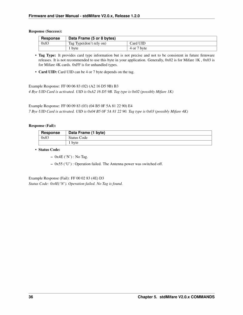
Response (Success):
Response Data Frame (5 or 8 bytes)0x83 Tag Type(don’t rely on) Card UID
1 byte 4 or 7 byte
• Tag Type: It provides card type information but is not precise and not to be consistent in future firmwarereleases. It is not recommended to use this byte in your application. Generally, 0x02 is for Mifare 1K , 0x03 isfor Mifare 4K cards. 0xFF is for unhandled types.
• Card UID: Card UID can be 4 or 7 byte depends on the tag.
Example Response: FF 00 06 83 (02) (A2 16 D5 9B) B34 Bye UID Card is activated. UID is 0xA2 16 D5 9B. Tag type is 0x02 (possibly Mifare 1K)
Example Response: FF 00 09 83 (03) (04 B5 0F 5A 81 22 90) E47 Bye UID Card is activated. UID is 0x04 B5 0F 5A 81 22 90. Tag type is 0x03 (possibly Mifare 4K)
Response (Fail):
Response Data Frame (1 byte)0x83 Status Code
1 byte
• Status Code:
– 0x4E (‘N’) : No Tag.
– 0x55 (‘U’) : Operation failed. The Antenna power was switched off.
Example Response (Fail): FF 00 02 83 (4E) D3Status Code: 0x4E(‘N’). Operation failed. No Tag is found.
36 Chapter 5. stdMifare V2.0.x COMMANDS

Firmware and User Manual - stdMifare V2.0.x, Release 1.2.0
5.4 CmdSeekForTag
• This command starts card search and activates a card as soon as it enters into the RF field and report the cardUID.
• It internally runs CmdActivateIdle loop to detect a card instead of the external controller sending activate com-mand continuously to detect a card.
• Once a card is detected, card UID is reported and search operation is ended. A new CmdSeekforTag commandis required to be sent to start seeking cards again.
• This command is disabled in Auto Mode, as they have similar purpose.
• This command will end searching if any command sent to the module/reader.
Because this command does not report the result immediately (card may enter into the RF field at any time), theremay be a requirement to get the current status that if CmdSeekForTag command is active or not. For example; anunexpected condition may cause the module/reader to reset (i.e. POR, reset or watchdog). In this case the externalcontroller may not be aware that the CmdSeekForTag tag command is interrupted.
• To overcome this situation, SeekForTagOnStartup setting can be enabled in device configuration. This willensure the module will start seek for tag command executed after a possible reset.
• Another way is to monitor the SREAD pin to check if the read is active or not. (depends on the SREADfunctionality settings in device configuration)
Other ways to search and activate a card is to send CmdActivateAll (or CmdActivateIdle) commands continuouslyfrom the external controller or using the Auto Mode.
Command:Command No Data Frame0x82
• This command has no parameters.
Example Command: FF 00 01 82 83Starts card seeking. Seeking card will be active until a card is detected or any command is received by the reader.
5.4. CmdSeekForTag 37
Firmware and User Manual - stdMifare V2.0.x, Release 1.2.0
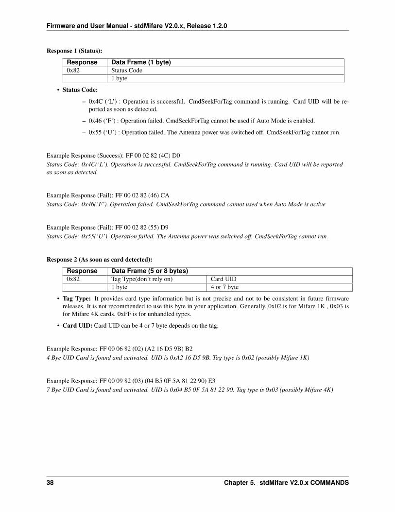
Response 1 (Status):
Response Data Frame (1 byte)0x82 Status Code
1 byte
• Status Code:
– 0x4C (‘L’) : Operation is successful. CmdSeekForTag command is running. Card UID will be re-ported as soon as detected.
– 0x46 (‘F’) : Operation failed. CmdSeekForTag cannot be used if Auto Mode is enabled.
– 0x55 (‘U’) : Operation failed. The Antenna power was switched off. CmdSeekForTag cannot run.
Example Response (Success): FF 00 02 82 (4C) D0Status Code: 0x4C(‘L’). Operation is successful. CmdSeekForTag command is running. Card UID will be reportedas soon as detected.
Example Response (Fail): FF 00 02 82 (46) CAStatus Code: 0x46(‘F’). Operation failed. CmdSeekForTag command cannot used when Auto Mode is active
Example Response (Fail): FF 00 02 82 (55) D9Status Code: 0x55(‘U’). Operation failed. The Antenna power was switched off. CmdSeekForTag cannot run.
Response 2 (As soon as card detected):
Response Data Frame (5 or 8 bytes)0x82 Tag Type(don’t rely on) Card UID
1 byte 4 or 7 byte
• Tag Type: It provides card type information but is not precise and not to be consistent in future firmwarereleases. It is not recommended to use this byte in your application. Generally, 0x02 is for Mifare 1K , 0x03 isfor Mifare 4K cards. 0xFF is for unhandled types.
• Card UID: Card UID can be 4 or 7 byte depends on the tag.
Example Response: FF 00 06 82 (02) (A2 16 D5 9B) B24 Bye UID Card is found and activated. UID is 0xA2 16 D5 9B. Tag type is 0x02 (possibly Mifare 1K)
Example Response: FF 00 09 82 (03) (04 B5 0F 5A 81 22 90) E37 Bye UID Card is found and activated. UID is 0x04 B5 0F 5A 81 22 90. Tag type is 0x03 (possibly Mifare 4K)
38 Chapter 5. stdMifare V2.0.x COMMANDS
Firmware and User Manual - stdMifare V2.0.x, Release 1.2.0
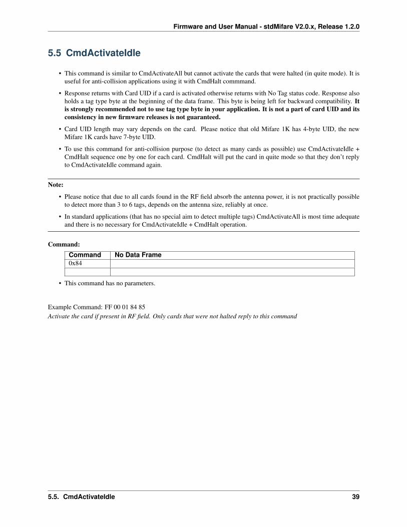
5.5 CmdActivateIdle
• This command is similar to CmdActivateAll but cannot activate the cards that were halted (in quite mode). It isuseful for anti-collision applications using it with CmdHalt commmand.
• Response returns with Card UID if a card is activated otherwise returns with No Tag status code. Response alsoholds a tag type byte at the beginning of the data frame. This byte is being left for backward compatibility. Itis strongly recommended not to use tag type byte in your application. It is not a part of card UID and itsconsistency in new firmware releases is not guaranteed.
• Card UID length may vary depends on the card. Please notice that old Mifare 1K has 4-byte UID, the newMifare 1K cards have 7-byte UID.
• To use this command for anti-collision purpose (to detect as many cards as possible) use CmdActivateIdle +CmdHalt sequence one by one for each card. CmdHalt will put the card in quite mode so that they don’t replyto CmdActivateIdle command again.
Note:
• Please notice that due to all cards found in the RF field absorb the antenna power, it is not practically possibleto detect more than 3 to 6 tags, depends on the antenna size, reliably at once.
• In standard applications (that has no special aim to detect multiple tags) CmdActivateAll is most time adequateand there is no necessary for CmdActivateIdle + CmdHalt operation.
Command:Command No Data Frame0x84
• This command has no parameters.
Example Command: FF 00 01 84 85Activate the card if present in RF field. Only cards that were not halted reply to this command
5.5. CmdActivateIdle 39

Firmware and User Manual - stdMifare V2.0.x, Release 1.2.0
Response (Success):
Response Data Frame (5 or 8 bytes)0x84 Tag Type(don’t rely on) Card UID
1 byte 4 or 7 byte
• Tag Type: It provides card type information but is not precise and not to be consistent in future firmwarereleases. It is not recommended to use this byte in your application. Generally, 0x02 is for Mifare 1K , 0x03 isfor Mifare 4K cards. 0xFF is for unhandled types.
• Card UID: Card UID can be 4 or 7 byte depends on the tag.
Example Response: FF 00 06 84 (02) (A2 16 D5 9B) B44 Bye UID Card is activated. UID is 0xA2 16 D5 9B. Tag type is 0x02 (possibly Mifare 1K)
Example Response: FF 00 09 84 (03) (04 B5 0F 5A 81 22 90) E57 Bye UID Card is activated. UID is 0x04 B5 0F 5A 81 22 90. Tag type is 0x03 (possibly Mifare 4K)
Response (Fail):
Response Data Frame (1 byte)0x84 Status Code
1 byte
• Status Code:
– 0x4E (‘N’) : No Tag.
– 0x55 (‘U’) : Operation failed. The Antenna power was switched off.
Example Response (Fail): FF 00 02 84 (4E) D4Status Code: 0x4E(‘N’). Operation failed. No Tag is found.
40 Chapter 5. stdMifare V2.0.x COMMANDS
Firmware and User Manual - stdMifare V2.0.x, Release 1.2.0
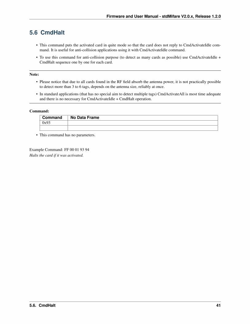
5.6 CmdHalt
• This command puts the activated card in quite mode so that the card does not reply to CmdActivateIdle com-mand. It is useful for anti-collision applications using it with CmdActivateIdle command.
• To use this command for anti-collision purpose (to detect as many cards as possible) use CmdActivateIdle +CmdHalt sequence one by one for each card.
Note:
• Please notice that due to all cards found in the RF field absorb the antenna power, it is not practically possibleto detect more than 3 to 6 tags, depends on the antenna size, reliably at once.
• In standard applications (that has no special aim to detect multiple tags) CmdActivateAll is most time adequateand there is no necessary for CmdActivateIdle + CmdHalt operation.
Command:Command No Data Frame0x93
• This command has no parameters.
Example Command: FF 00 01 93 94Halts the card if it was activated.
5.6. CmdHalt 41
Firmware and User Manual - stdMifare V2.0.x, Release 1.2.0
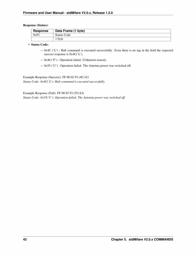
Response (Status):
Response Data Frame (1 byte)0x93 Status Code
1 byte
• Status Code:
– 0x4C (‘L’) : Halt command is executed successfully. Even there is no tag in the field the expectedsuccess response is 0x4C(‘L’).
– 0x46 (‘F’) : Operation failed. (Unknown reason)
– 0x55 (‘U’) : Operation failed. The Antenna power was switched off.
Example Response (Success): FF 00 02 93 (4C) E1Status Code: 0x4C(‘L’). Halt command is executed successfully.
Example Response (Fail): FF 00 02 93 (55) EAStatus Code: 0x55(‘U’). Operation failed. The Antenna power was switched off.
42 Chapter 5. stdMifare V2.0.x COMMANDS
Firmware and User Manual - stdMifare V2.0.x, Release 1.2.0
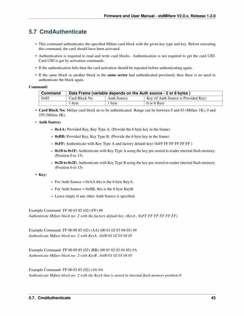
5.7 CmdAuthenticate
• This command authenticates the specified Mifare card block with the given key type and key. Before executingthis command, the card should have been activated.
• Authentication is required to read and write card blocks. Authentication is not required to get the card UID.Card UID is get by activation commands.
• If the authentication fails then the card activation should be repeated before authenticating again.
• If the same block or another block in the same sector had authenticated previously then there is no need toauthenticate the block again.
Command:Command Data Frame (variable depends on the Auth source - 2 or 8 bytes )0x85 Card Block No Auth Source Key (if Auth Source is Provided Key)
1 byte 1 byte 0 or 6 Byte
• Card Block No: Mifare card block no to be authenticated. Range can be between 0 and 63 (Mifare 1K), 0 and255 (Mifare 4K).
• Auth Source:
– 0xAA: Provided Key, Key Type A. (Provide the 6 byte key in the frame)
– 0xBB: Provided Key, Key Type B. (Provide the 6 byte key in the frame)
– 0xFF: Authenticate with Key Type A and factory default key( 0xFF FF FF FF FF FF )
– 0x10 to 0x1F: Authenticate with Key Type A using the key pre-stored in reader internal flash memory.(Position 0 to 15)
– 0x20 to 0x2F: Authenticate with Key Type B using the key pre-stored in reader internal flash memory.(Position 0 to 15)
• Key:
– For Auth Source = 0xAA this is the 6 byte KeyA.
– For Auth Source = 0xBB, this is the 6 byte KeyB.
– Leave empty if any other Auth Source is specified.
Example Command: FF 00 03 85 (02) (FF) 89Authenticate Mifare block no: 2 with the factory default key. (KeyA , 0xFF FF FF FF FF FF)
Example Command: FF 00 09 85 (02) (AA) (00 01 02 03 04 05) 49Authenticate Mifare block no: 2 with KeyA , 0x00 01 02 03 04 05
Example Command: FF 00 09 85 (02) (BB) (00 01 02 03 04 05) 5AAuthenticate Mifare block no: 2 with KeyB , 0x00 01 02 03 04 05
Example Command: FF 00 03 85 (02) (10) 9AAuthenticate Mifare block no: 2 with the KeyA that is stored in internal flash memory position:0
5.7. CmdAuthenticate 43
Firmware and User Manual - stdMifare V2.0.x, Release 1.2.0
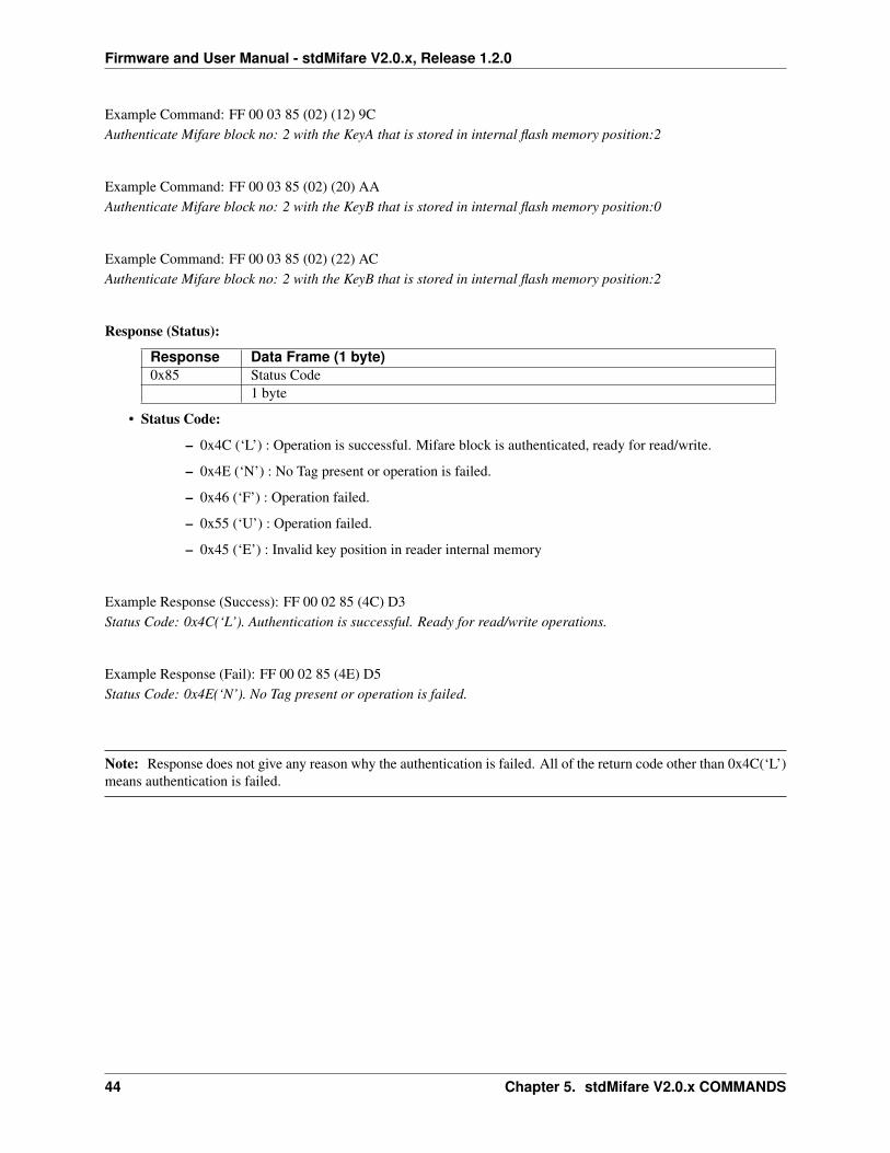
Example Command: FF 00 03 85 (02) (12) 9CAuthenticate Mifare block no: 2 with the KeyA that is stored in internal flash memory position:2
Example Command: FF 00 03 85 (02) (20) AAAuthenticate Mifare block no: 2 with the KeyB that is stored in internal flash memory position:0
Example Command: FF 00 03 85 (02) (22) ACAuthenticate Mifare block no: 2 with the KeyB that is stored in internal flash memory position:2
Response (Status):
Response Data Frame (1 byte)0x85 Status Code
1 byte
• Status Code:
– 0x4C (‘L’) : Operation is successful. Mifare block is authenticated, ready for read/write.
– 0x4E (‘N’) : No Tag present or operation is failed.
– 0x46 (‘F’) : Operation failed.
– 0x55 (‘U’) : Operation failed.
– 0x45 (‘E’) : Invalid key position in reader internal memory
Example Response (Success): FF 00 02 85 (4C) D3Status Code: 0x4C(‘L’). Authentication is successful. Ready for read/write operations.
Example Response (Fail): FF 00 02 85 (4E) D5Status Code: 0x4E(‘N’). No Tag present or operation is failed.
Note: Response does not give any reason why the authentication is failed. All of the return code other than 0x4C(‘L’)means authentication is failed.
44 Chapter 5. stdMifare V2.0.x COMMANDS
Firmware and User Manual - stdMifare V2.0.x, Release 1.2.0
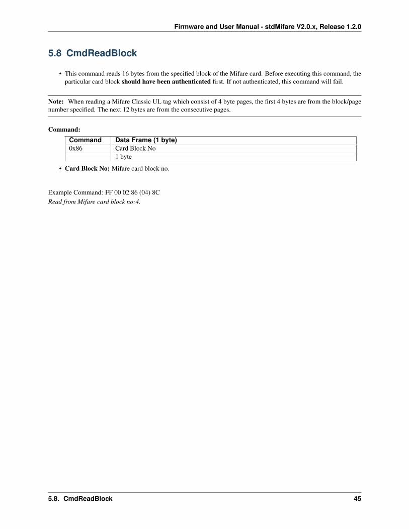
5.8 CmdReadBlock
• This command reads 16 bytes from the specified block of the Mifare card. Before executing this command, theparticular card block should have been authenticated first. If not authenticated, this command will fail.
Note: When reading a Mifare Classic UL tag which consist of 4 byte pages, the first 4 bytes are from the block/pagenumber specified. The next 12 bytes are from the consecutive pages.
Command:Command Data Frame (1 byte)0x86 Card Block No
1 byte
• Card Block No: Mifare card block no.
Example Command: FF 00 02 86 (04) 8CRead from Mifare card block no:4.
5.8. CmdReadBlock 45
Firmware and User Manual - stdMifare V2.0.x, Release 1.2.0
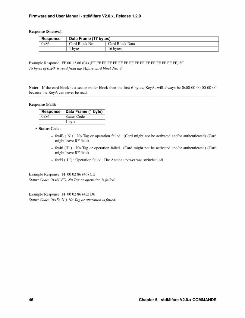
Response (Success):
Response Data Frame (17 bytes)0x86 Card Block No Card Block Data
1 byte 16 bytes
Example Response: FF 00 12 86 (04) (FF FF FF FF FF FF FF FF FF FF FF FF FF FF FF FF) 8C16 bytes of 0xFF is read from the Mifare card block No: 4.
Note: If the card block is a sector trailer block then the first 6 bytes, KeyA, will always be 0x00 00 00 00 00 00because the KeyA can never be read.
Response (Fail):
Response Data Frame (1 byte)0x86 Status Code
1 byte
• Status Code:
– 0x4E (‘N’) : No Tag or operation failed. (Card might not be activated and/or authenticated) (Cardmight leave RF field)
– 0x46 (‘F’) : No Tag or operation failed. (Card might not be activated and/or authenticated) (Cardmight leave RF field)
– 0x55 (‘U’) : Operation failed. The Antenna power was switched off.
Example Response: FF 00 02 86 (46) CEStatus Code: 0x46(‘F’). No Tag or operation is failed.
Example Response: FF 00 02 86 (4E) D6Status Code: 0x4E(‘N’). No Tag or operation is failed.
46 Chapter 5. stdMifare V2.0.x COMMANDS
Firmware and User Manual - stdMifare V2.0.x, Release 1.2.0
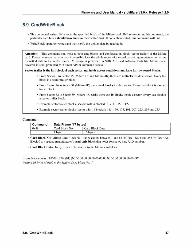
5.9 CmdWriteBlock
• This command writes 16 bytes to the specified block of the Mifare card. Before executing this command, theparticular card block should have been authenticated first. If not authenticated, this command will fail.
• WriteBlock operation writes and then verify the written data by reading it.
Attention: This command can write to both data blocks and configuration block (sector trailer) of the Mifarecard. Please be aware that you may irreversibly lock the whole sector of the card by writing unintended or wrongformatted data to the sector trailer. Misusage is prevented in SDK API, and software tools like Mifare Panelhowever it is not protected with direct API or command access.
Sector trailer is the last block of each sector and holds access conditions and keys for the owned blocks.
• From Sector 0 to Sector 15 (Mifare 1K and Mifare 4K) there are 4 blocks inside a sector. Every lastblock is a sector trailer block.
• From Sector 16 to Sector 31 (Mifare 4K) there are 4 blocks inside a sector. Every last block is a sectortrailer block.
• From Sector 32 to Sector 39 (Mifare 4K cards) there are 16 blocks inside a sector. Every last block isa sector trailer block.
• Example sector trailer blocks (sectors with 4 blocks): 3, 7, 11, 15 ... 127
• Example sector trailer blocks (sector with 16 blocks): 143, 159, 175, 191, 207, 223, 239 and 255
Command:Command Data Frame (17 bytes)0x89 Card Block No Card Block Data
1 byte 16 bytes
• Card Block No: Mifare Card Block No. Range can be between 1 and 63 (Mifare 1K), 1 and 255 (Mifare 4K).Block 0 is a special manufacturer’s read-only block that holds formatted card UID number.
• Card Block Data: 16 byte data to be written to the Mifare card block.
Example Command: FF 00 12 89 (01) (00 00 00 00 00 00 00 00 00 00 00 00 00 00 00 00) 9CWriting 16 bytes of 0x00 to the Mifare Card Block No: 1
5.9. CmdWriteBlock 47
Firmware and User Manual - stdMifare V2.0.x, Release 1.2.0
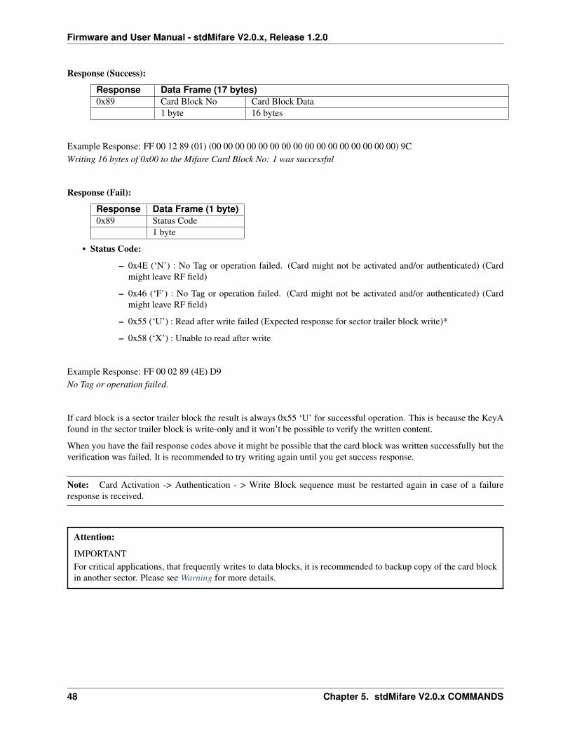
Response (Success):
Response Data Frame (17 bytes)0x89 Card Block No Card Block Data
1 byte 16 bytes
Example Response: FF 00 12 89 (01) (00 00 00 00 00 00 00 00 00 00 00 00 00 00 00 00) 9CWriting 16 bytes of 0x00 to the Mifare Card Block No: 1 was successful
Response (Fail):
Response Data Frame (1 byte)0x89 Status Code
1 byte
• Status Code:
– 0x4E (‘N’) : No Tag or operation failed. (Card might not be activated and/or authenticated) (Cardmight leave RF field)
– 0x46 (‘F’) : No Tag or operation failed. (Card might not be activated and/or authenticated) (Cardmight leave RF field)
– 0x55 (‘U’) : Read after write failed (Expected response for sector trailer block write)*
– 0x58 (‘X’) : Unable to read after write
Example Response: FF 00 02 89 (4E) D9No Tag or operation failed.
If card block is a sector trailer block the result is always 0x55 ‘U’ for successful operation. This is because the KeyAfound in the sector trailer block is write-only and it won’t be possible to verify the written content.
When you have the fail response codes above it might be possible that the card block was written successfully but theverification was failed. It is recommended to try writing again until you get success response.
Note: Card Activation -> Authentication - > Write Block sequence must be restarted again in case of a failureresponse is received.
Attention:
IMPORTANTFor critical applications, that frequently writes to data blocks, it is recommended to backup copy of the card blockin another sector. Please see Warning for more details.
48 Chapter 5. stdMifare V2.0.x COMMANDS
Firmware and User Manual - stdMifare V2.0.x, Release 1.2.0
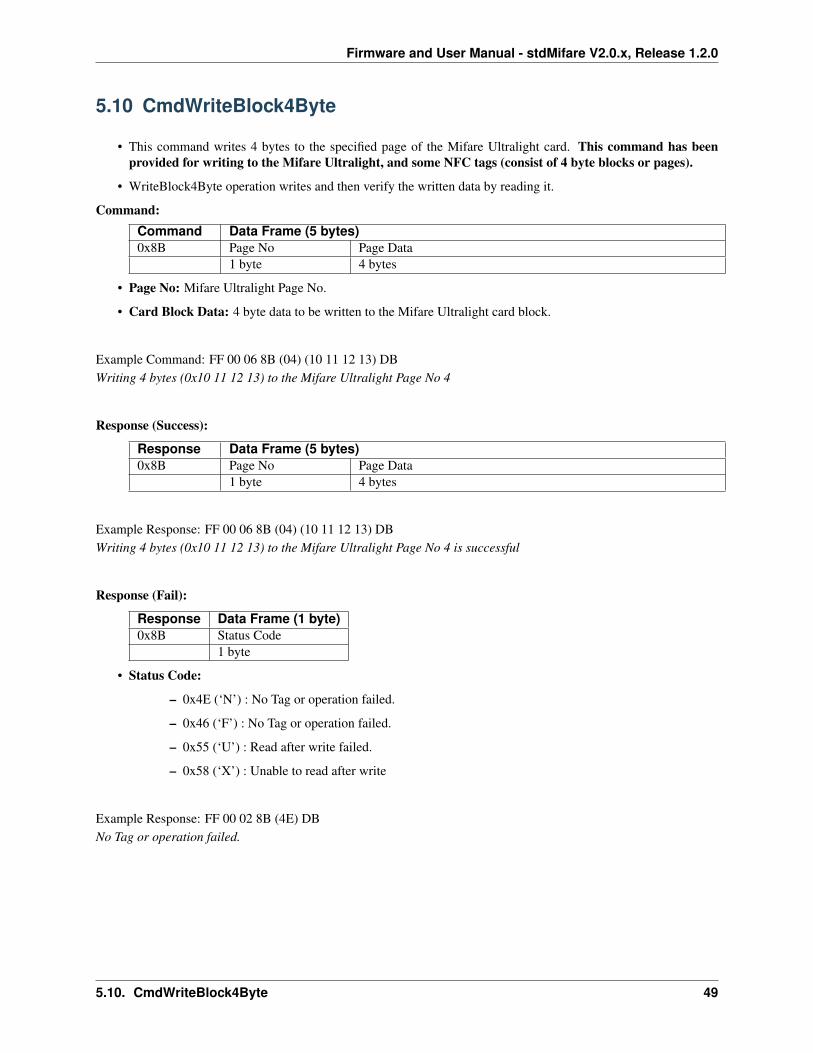
5.10 CmdWriteBlock4Byte
• This command writes 4 bytes to the specified page of the Mifare Ultralight card. This command has beenprovided for writing to the Mifare Ultralight, and some NFC tags (consist of 4 byte blocks or pages).
• WriteBlock4Byte operation writes and then verify the written data by reading it.
Command:Command Data Frame (5 bytes)0x8B Page No Page Data
1 byte 4 bytes
• Page No: Mifare Ultralight Page No.
• Card Block Data: 4 byte data to be written to the Mifare Ultralight card block.
Example Command: FF 00 06 8B (04) (10 11 12 13) DBWriting 4 bytes (0x10 11 12 13) to the Mifare Ultralight Page No 4
Response (Success):
Response Data Frame (5 bytes)0x8B Page No Page Data
1 byte 4 bytes
Example Response: FF 00 06 8B (04) (10 11 12 13) DBWriting 4 bytes (0x10 11 12 13) to the Mifare Ultralight Page No 4 is successful
Response (Fail):
Response Data Frame (1 byte)0x8B Status Code
1 byte
• Status Code:
– 0x4E (‘N’) : No Tag or operation failed.
– 0x46 (‘F’) : No Tag or operation failed.
– 0x55 (‘U’) : Read after write failed.
– 0x58 (‘X’) : Unable to read after write
Example Response: FF 00 02 8B (4E) DBNo Tag or operation failed.
5.10. CmdWriteBlock4Byte 49
Firmware and User Manual - stdMifare V2.0.x, Release 1.2.0
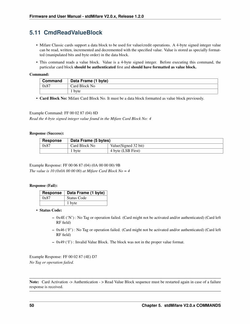
5.11 CmdReadValueBlock
• Mifare Classic cards support a data block to be used for value/credit operations. A 4-byte signed integer valuecan be read, written, incremented and decremented with the specified value. Value is stored as specially format-ted (manipulated bits and byte order) in the data block.
• This command reads a value block. Value is a 4-byte signed integer. Before executing this command, theparticular card block should be authenticated first and should have formatted as value block.
Command:Command Data Frame (1 byte)0x87 Card Block No
1 byte
• Card Block No: Mifare Card Block No. It must be a data block formatted as value block previously.
Example Command: FF 00 02 87 (04) 8DRead the 4-byte signed integer value found in the Mifare Card Block No: 4
Response (Success):
Response Data Frame (5 bytes)0x87 Card Block No Value(Signed 32 bit)
1 byte 4 byte (LSB First)
Example Response: FF 00 06 87 (04) (0A 00 00 00) 9BThe value is 10 (0x0A 00 00 00) at Mifare Card Block No = 4
Response (Fail):
Response Data Frame (1 byte)0x87 Status Code
1 byte
• Status Code:
– 0x4E (‘N’) : No Tag or operation failed. (Card might not be activated and/or authenticated) (Card leftRF field)
– 0x46 (‘F’) : No Tag or operation failed. (Card might not be activated and/or authenticated) (Card leftRF field)
– 0x49 (‘I’) : Invalid Value Block. The block was not in the proper value format.
Example Response: FF 00 02 87 (4E) D7No Tag or operation failed.
Note: Card Activation -> Authentication - > Read Value Block sequence must be restarted again in case of a failureresponse is received.
50 Chapter 5. stdMifare V2.0.x COMMANDS
Firmware and User Manual - stdMifare V2.0.x, Release 1.2.0
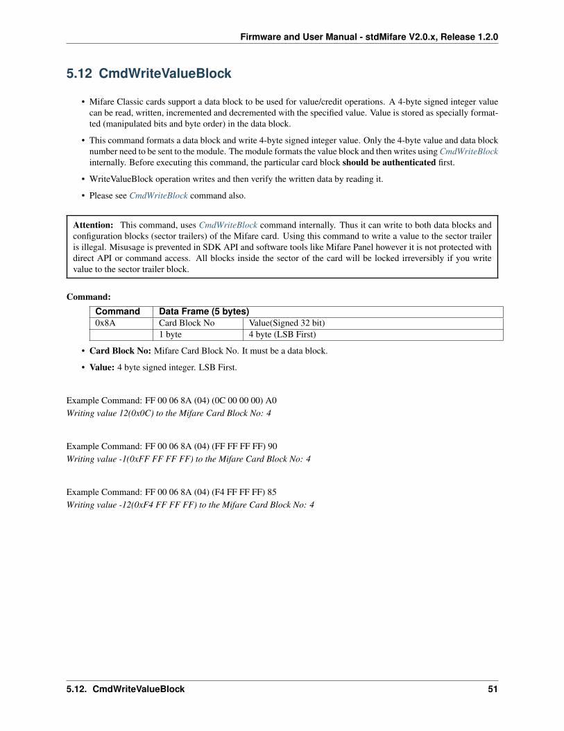
5.12 CmdWriteValueBlock
• Mifare Classic cards support a data block to be used for value/credit operations. A 4-byte signed integer valuecan be read, written, incremented and decremented with the specified value. Value is stored as specially format-ted (manipulated bits and byte order) in the data block.
• This command formats a data block and write 4-byte signed integer value. Only the 4-byte value and data blocknumber need to be sent to the module. The module formats the value block and then writes using CmdWriteBlockinternally. Before executing this command, the particular card block should be authenticated first.
• WriteValueBlock operation writes and then verify the written data by reading it.
• Please see CmdWriteBlock command also.
Attention: This command, uses CmdWriteBlock command internally. Thus it can write to both data blocks andconfiguration blocks (sector trailers) of the Mifare card. Using this command to write a value to the sector traileris illegal. Misusage is prevented in SDK API and software tools like Mifare Panel however it is not protected withdirect API or command access. All blocks inside the sector of the card will be locked irreversibly if you writevalue to the sector trailer block.
Command:Command Data Frame (5 bytes)0x8A Card Block No Value(Signed 32 bit)
1 byte 4 byte (LSB First)
• Card Block No: Mifare Card Block No. It must be a data block.
• Value: 4 byte signed integer. LSB First.
Example Command: FF 00 06 8A (04) (0C 00 00 00) A0Writing value 12(0x0C) to the Mifare Card Block No: 4
Example Command: FF 00 06 8A (04) (FF FF FF FF) 90Writing value -1(0xFF FF FF FF) to the Mifare Card Block No: 4
Example Command: FF 00 06 8A (04) (F4 FF FF FF) 85Writing value -12(0xF4 FF FF FF) to the Mifare Card Block No: 4
5.12. CmdWriteValueBlock 51
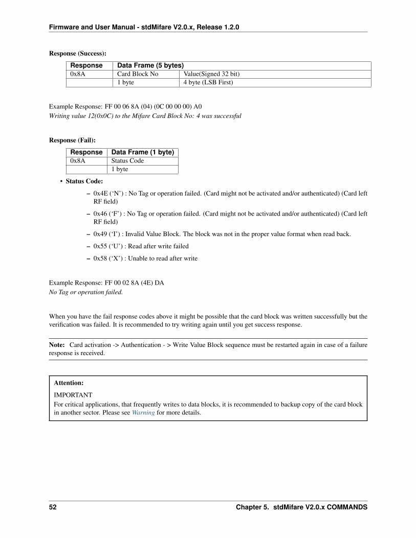
Firmware and User Manual - stdMifare V2.0.x, Release 1.2.0
Response (Success):
Response Data Frame (5 bytes)0x8A Card Block No Value(Signed 32 bit)
1 byte 4 byte (LSB First)
Example Response: FF 00 06 8A (04) (0C 00 00 00) A0Writing value 12(0x0C) to the Mifare Card Block No: 4 was successful
Response (Fail):
Response Data Frame (1 byte)0x8A Status Code
1 byte
• Status Code:
– 0x4E (‘N’) : No Tag or operation failed. (Card might not be activated and/or authenticated) (Card leftRF field)
– 0x46 (‘F’) : No Tag or operation failed. (Card might not be activated and/or authenticated) (Card leftRF field)
– 0x49 (‘I’) : Invalid Value Block. The block was not in the proper value format when read back.
– 0x55 (‘U’) : Read after write failed
– 0x58 (‘X’) : Unable to read after write
Example Response: FF 00 02 8A (4E) DANo Tag or operation failed.
When you have the fail response codes above it might be possible that the card block was written successfully but theverification was failed. It is recommended to try writing again until you get success response.
Note: Card activation -> Authentication - > Write Value Block sequence must be restarted again in case of a failureresponse is received.
Attention:
IMPORTANTFor critical applications, that frequently writes to data blocks, it is recommended to backup copy of the card blockin another sector. Please see Warning for more details.
52 Chapter 5. stdMifare V2.0.x COMMANDS
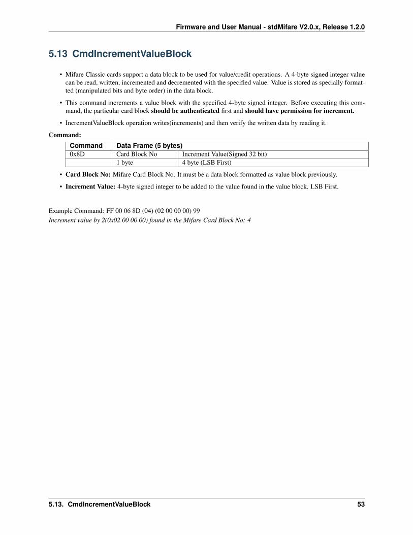
Firmware and User Manual - stdMifare V2.0.x, Release 1.2.0
5.13 CmdIncrementValueBlock
• Mifare Classic cards support a data block to be used for value/credit operations. A 4-byte signed integer valuecan be read, written, incremented and decremented with the specified value. Value is stored as specially format-ted (manipulated bits and byte order) in the data block.
• This command increments a value block with the specified 4-byte signed integer. Before executing this com-mand, the particular card block should be authenticated first and should have permission for increment.
• IncrementValueBlock operation writes(increments) and then verify the written data by reading it.
Command:Command Data Frame (5 bytes)0x8D Card Block No Increment Value(Signed 32 bit)
1 byte 4 byte (LSB First)
• Card Block No: Mifare Card Block No. It must be a data block formatted as value block previously.
• Increment Value: 4-byte signed integer to be added to the value found in the value block. LSB First.
Example Command: FF 00 06 8D (04) (02 00 00 00) 99Increment value by 2(0x02 00 00 00) found in the Mifare Card Block No: 4
5.13. CmdIncrementValueBlock 53

Firmware and User Manual - stdMifare V2.0.x, Release 1.2.0
Response (Success):
Response Data Frame (5 bytes)0x8D Card Block No Final Value(Signed 32 bit)
1 byte 4 byte (LSB First)
Example Response: FF 00 06 8D (04) (0E 00 00 00) A5Final value after the increment is reported back. The final value is 14 (0x0E 00 00 00) at Mifare Card Block No = 4
Response (Fail):
Response Data Frame (1 byte)0x8D Status Code
1 byte
• Status Code:
– 0x4E (‘N’) : No Tag or operation failed. (Card might not be activated and/or authenticated) (Card leftRF field)
– 0x46 (‘F’) : No Tag or operation failed. (Card might not be activated and/or authenticated) (Card leftRF field)
– 0x49 (‘I’) : Invalid Value Block. The block was not in the proper value format when read back.
Example Response: FF 00 02 8D (46) D5No Tag or operation failed.
When you have the fail response codes above it might be possible that the card block was written successfully but theverification was failed. It is recommended to first read the value and then increment again if necessary.
Note: Card Activation -> Authentication sequence must be restarted again in case of a failure response is received.
Attention:
IMPORTANTFor critical applications, that frequently writes to data blocks, it is recommended to backup copy of the card blockin another sector. Please see Warning for more details.
54 Chapter 5. stdMifare V2.0.x COMMANDS
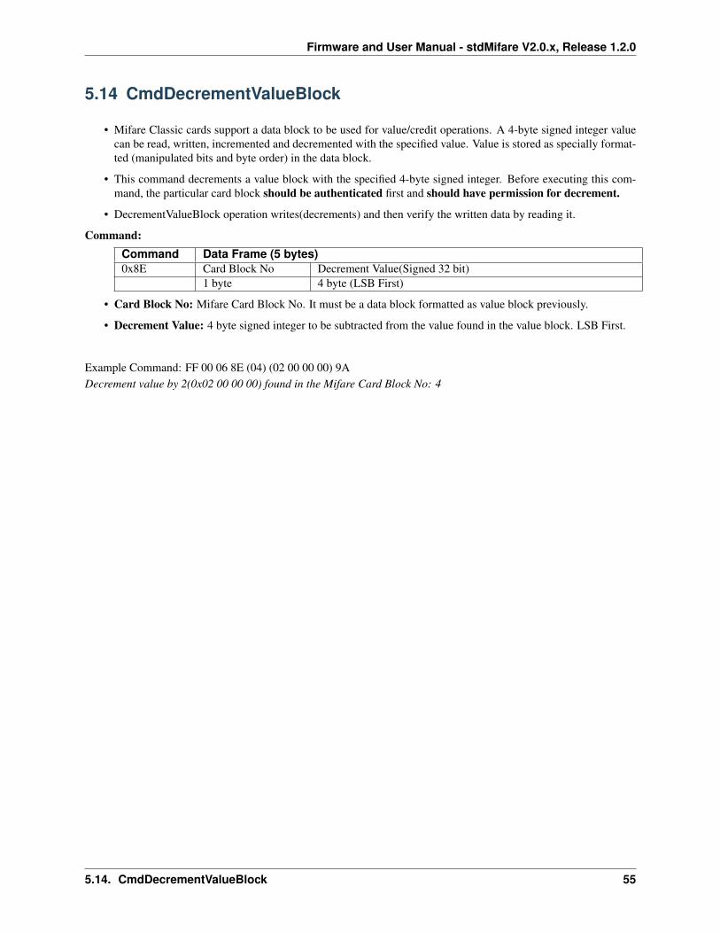
Firmware and User Manual - stdMifare V2.0.x, Release 1.2.0
5.14 CmdDecrementValueBlock
• Mifare Classic cards support a data block to be used for value/credit operations. A 4-byte signed integer valuecan be read, written, incremented and decremented with the specified value. Value is stored as specially format-ted (manipulated bits and byte order) in the data block.
• This command decrements a value block with the specified 4-byte signed integer. Before executing this com-mand, the particular card block should be authenticated first and should have permission for decrement.
• DecrementValueBlock operation writes(decrements) and then verify the written data by reading it.
Command:Command Data Frame (5 bytes)0x8E Card Block No Decrement Value(Signed 32 bit)
1 byte 4 byte (LSB First)
• Card Block No: Mifare Card Block No. It must be a data block formatted as value block previously.
• Decrement Value: 4 byte signed integer to be subtracted from the value found in the value block. LSB First.
Example Command: FF 00 06 8E (04) (02 00 00 00) 9ADecrement value by 2(0x02 00 00 00) found in the Mifare Card Block No: 4
5.14. CmdDecrementValueBlock 55
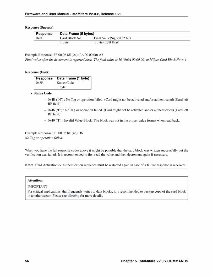
Firmware and User Manual - stdMifare V2.0.x, Release 1.2.0
Response (Success):
Response Data Frame (5 bytes)0x8E Card Block No Final Value(Signed 32 bit)
1 byte 4 byte (LSB First)
Example Response: FF 00 06 8E (04) (0A 00 00 00) A2Final value after the decrement is reported back. The final value is 10 (0x0A 00 00 00) at Mifare Card Block No = 4
Response (Fail):
Response Data Frame (1 byte)0x8E Status Code
1 byte
• Status Code:
– 0x4E (‘N’) : No Tag or operation failed. (Card might not be activated and/or authenticated) (Card leftRF field)
– 0x46 (‘F’) : No Tag or operation failed. (Card might not be activated and/or authenticated) (Card leftRF field)
– 0x49 (‘I’) : Invalid Value Block. The block was not in the proper value format when read back.
Example Response: FF 00 02 8E (46) D6No Tag or operation failed.
When you have the fail response codes above it might be possible that the card block was written successfully but theverification was failed. It is recommended to first read the value and then decrement again if necessary.
Note: Card Activation -> Authentication sequence must be restarted again in case of a failure response is received.
Attention:
IMPORTANTFor critical applications, that frequently writes to data blocks, it is recommended to backup copy of the card blockin another sector. Please see Warning for more details.
56 Chapter 5. stdMifare V2.0.x COMMANDS
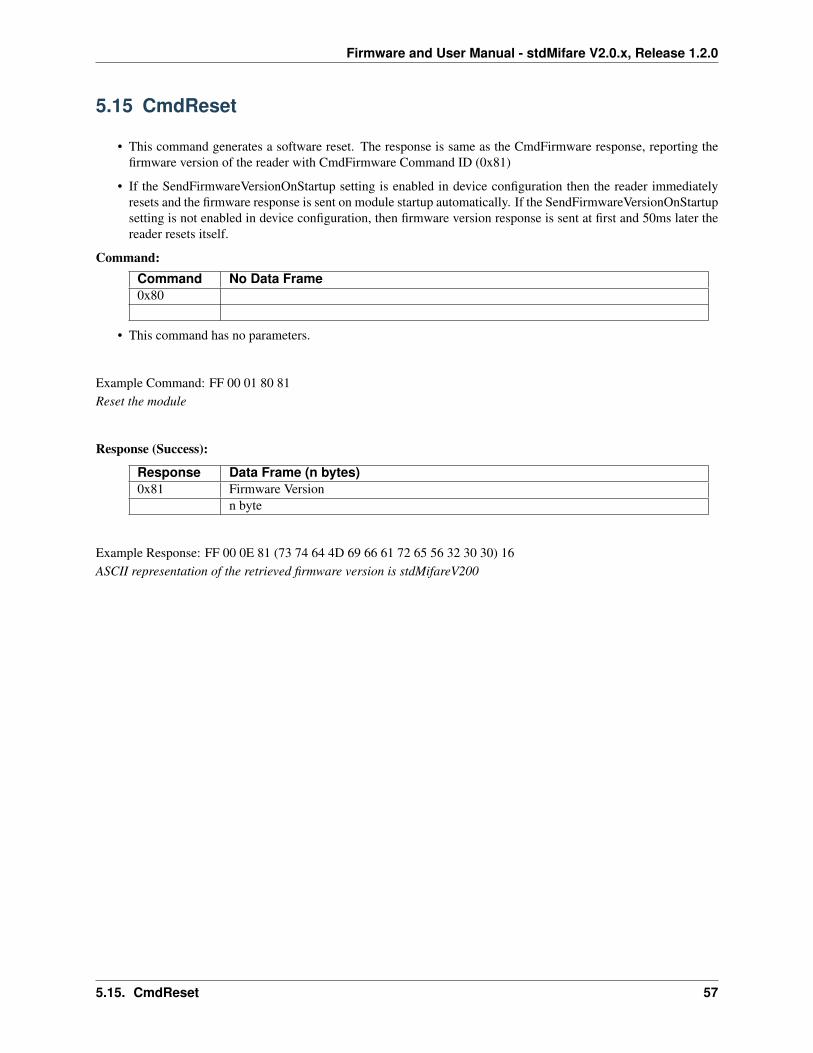
Firmware and User Manual - stdMifare V2.0.x, Release 1.2.0
5.15 CmdReset
• This command generates a software reset. The response is same as the CmdFirmware response, reporting thefirmware version of the reader with CmdFirmware Command ID (0x81)
• If the SendFirmwareVersionOnStartup setting is enabled in device configuration then the reader immediatelyresets and the firmware response is sent on module startup automatically. If the SendFirmwareVersionOnStartupsetting is not enabled in device configuration, then firmware version response is sent at first and 50ms later thereader resets itself.
Command:Command No Data Frame0x80
• This command has no parameters.
Example Command: FF 00 01 80 81Reset the module
Response (Success):
Response Data Frame (n bytes)0x81 Firmware Version
n byte
Example Response: FF 00 0E 81 (73 74 64 4D 69 66 61 72 65 56 32 30 30) 16ASCII representation of the retrieved firmware version is stdMifareV200
5.15. CmdReset 57
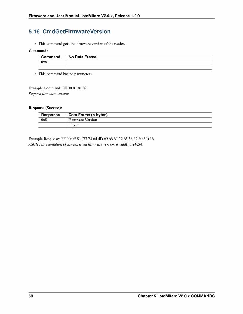
Firmware and User Manual - stdMifare V2.0.x, Release 1.2.0
5.16 CmdGetFirmwareVersion
• This command gets the firmware version of the reader.
Command:Command No Data Frame0x81
• This command has no parameters.
Example Command: FF 00 01 81 82Request firmware version
Response (Success):
Response Data Frame (n bytes)0x81 Firmware Version
n byte
Example Response: FF 00 0E 81 (73 74 64 4D 69 66 61 72 65 56 32 30 30) 16ASCII representation of the retrieved firmware version is stdMifareV200
58 Chapter 5. stdMifare V2.0.x COMMANDS
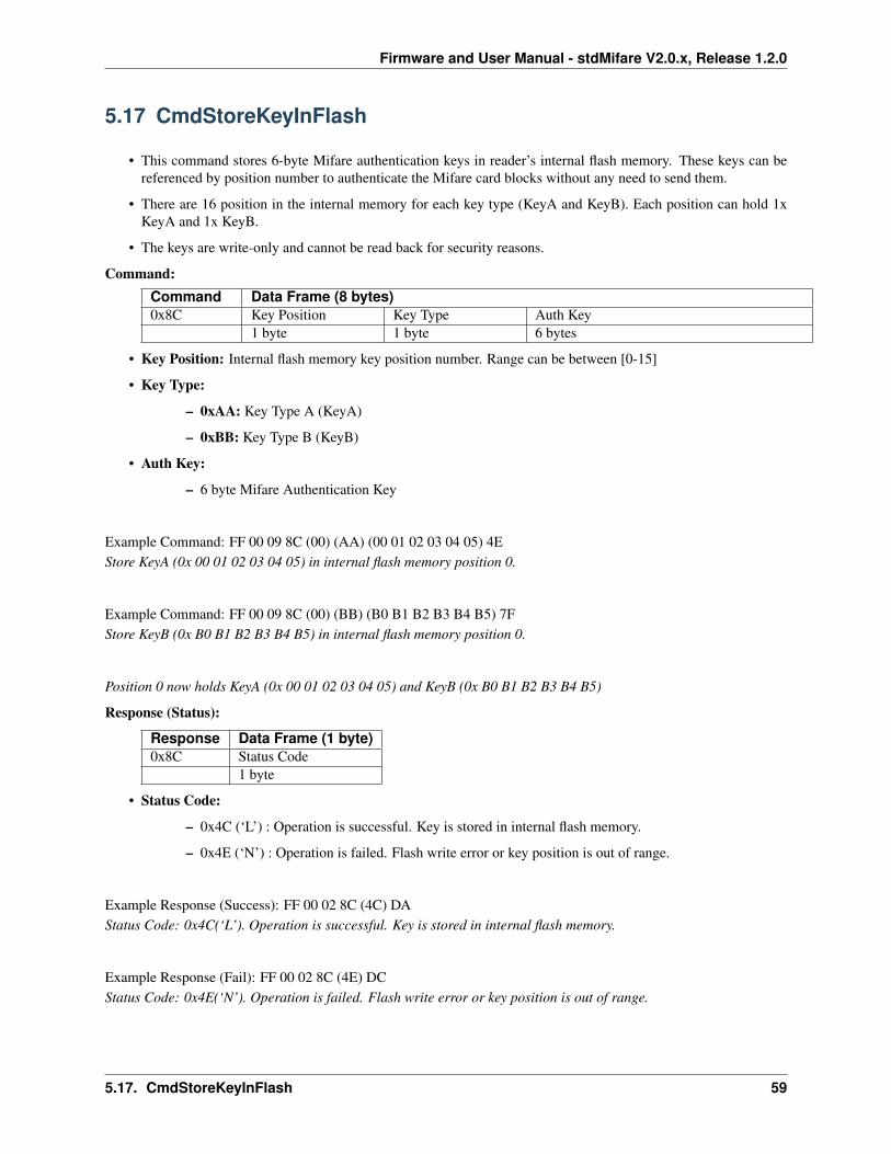
Firmware and User Manual - stdMifare V2.0.x, Release 1.2.0
5.17 CmdStoreKeyInFlash
• This command stores 6-byte Mifare authentication keys in reader’s internal flash memory. These keys can bereferenced by position number to authenticate the Mifare card blocks without any need to send them.
• There are 16 position in the internal memory for each key type (KeyA and KeyB). Each position can hold 1xKeyA and 1x KeyB.
• The keys are write-only and cannot be read back for security reasons.
Command:Command Data Frame (8 bytes)0x8C Key Position Key Type Auth Key
1 byte 1 byte 6 bytes
• Key Position: Internal flash memory key position number. Range can be between [0-15]
• Key Type:
– 0xAA: Key Type A (KeyA)
– 0xBB: Key Type B (KeyB)
• Auth Key:
– 6 byte Mifare Authentication Key
Example Command: FF 00 09 8C (00) (AA) (00 01 02 03 04 05) 4EStore KeyA (0x 00 01 02 03 04 05) in internal flash memory position 0.
Example Command: FF 00 09 8C (00) (BB) (B0 B1 B2 B3 B4 B5) 7FStore KeyB (0x B0 B1 B2 B3 B4 B5) in internal flash memory position 0.
Position 0 now holds KeyA (0x 00 01 02 03 04 05) and KeyB (0x B0 B1 B2 B3 B4 B5)
Response (Status):
Response Data Frame (1 byte)0x8C Status Code
1 byte
• Status Code:
– 0x4C (‘L’) : Operation is successful. Key is stored in internal flash memory.
– 0x4E (‘N’) : Operation is failed. Flash write error or key position is out of range.
Example Response (Success): FF 00 02 8C (4C) DAStatus Code: 0x4C(‘L’). Operation is successful. Key is stored in internal flash memory.
Example Response (Fail): FF 00 02 8C (4E) DCStatus Code: 0x4E(‘N’). Operation is failed. Flash write error or key position is out of range.
5.17. CmdStoreKeyInFlash 59
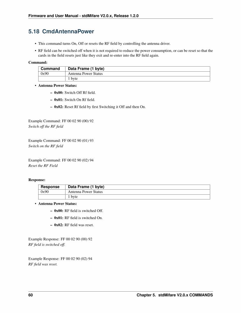
Firmware and User Manual - stdMifare V2.0.x, Release 1.2.0
5.18 CmdAntennaPower
• This command turns On, Off or resets the RF field by controlling the antenna driver.
• RF field can be switched off when it is not required to reduce the power consumption, or can be reset so that thecards in the field resets just like they exit and re-enter into the RF field again.
Command:Command Data Frame (1 byte)0x90 Antenna Power Status
1 byte
• Antenna Power Status:
– 0x00: Switch Off Rf field.
– 0x01: Switch On Rf field.
– 0x02: Reset Rf field by first Switching it Off and then On.
Example Command: FF 00 02 90 (00) 92Switch off the RF field
Example Command: FF 00 02 90 (01) 93Switch on the RF field
Example Command: FF 00 02 90 (02) 94Reset the RF Field
Response:
Response Data Frame (1 byte)0x90 Antenna Power Status
1 byte
• Antenna Power Status:
– 0x00: RF field is switched Off.
– 0x01: RF field is switched On.
– 0x02: RF field was reset.
Example Response: FF 00 02 90 (00) 92RF field is switched off.
Example Response: FF 00 02 90 (02) 94RF field was reset.
60 Chapter 5. stdMifare V2.0.x COMMANDS
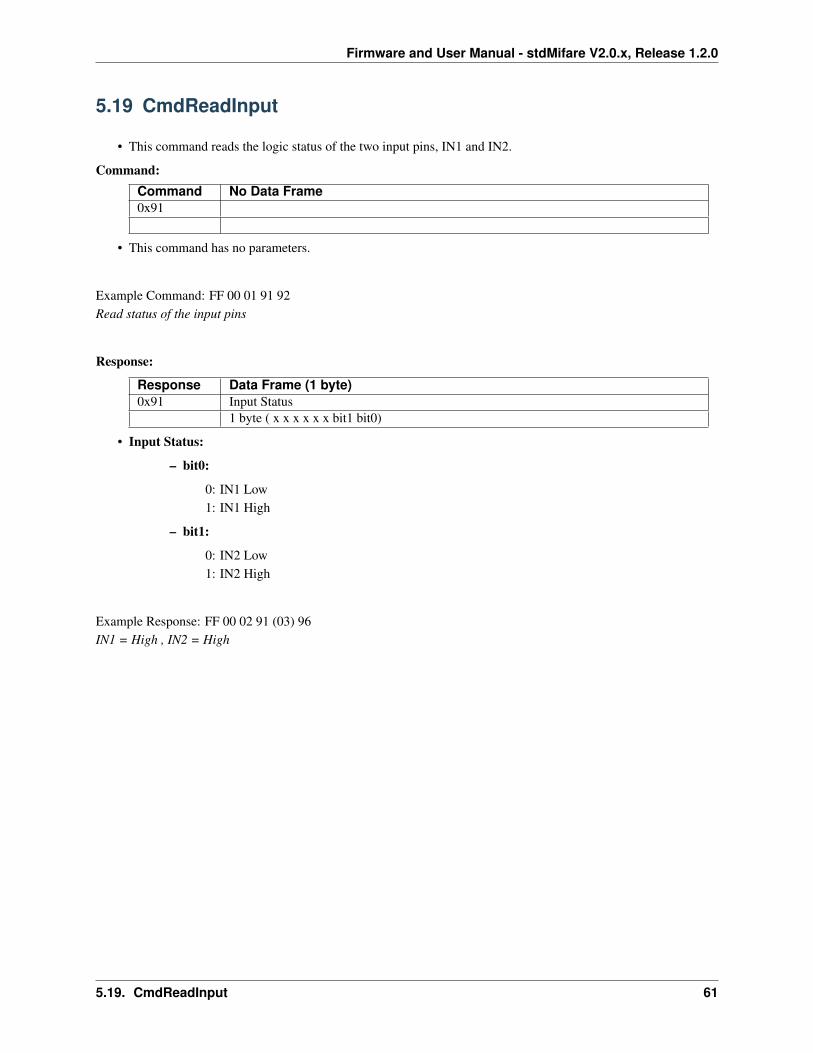
Firmware and User Manual - stdMifare V2.0.x, Release 1.2.0
5.19 CmdReadInput
• This command reads the logic status of the two input pins, IN1 and IN2.
Command:Command No Data Frame0x91
• This command has no parameters.
Example Command: FF 00 01 91 92Read status of the input pins
Response:
Response Data Frame (1 byte)0x91 Input Status
1 byte ( x x x x x x bit1 bit0)
• Input Status:
– bit0:
0: IN1 Low1: IN1 High
– bit1:
0: IN2 Low1: IN2 High
Example Response: FF 00 02 91 (03) 96IN1 = High , IN2 = High
5.19. CmdReadInput 61
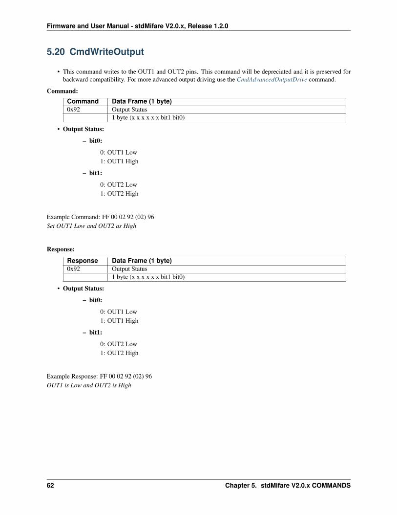
Firmware and User Manual - stdMifare V2.0.x, Release 1.2.0
5.20 CmdWriteOutput
• This command writes to the OUT1 and OUT2 pins. This command will be depreciated and it is preserved forbackward compatibility. For more advanced output driving use the CmdAdvancedOutputDrive command.
Command:Command Data Frame (1 byte)0x92 Output Status
1 byte (x x x x x x bit1 bit0)
• Output Status:
– bit0:
0: OUT1 Low1: OUT1 High
– bit1:
0: OUT2 Low1: OUT2 High
Example Command: FF 00 02 92 (02) 96Set OUT1 Low and OUT2 as High
Response:
Response Data Frame (1 byte)0x92 Output Status
1 byte (x x x x x x bit1 bit0)
• Output Status:
– bit0:
0: OUT1 Low1: OUT1 High
– bit1:
0: OUT2 Low1: OUT2 High
Example Response: FF 00 02 92 (02) 96OUT1 is Low and OUT2 is High
62 Chapter 5. stdMifare V2.0.x COMMANDS
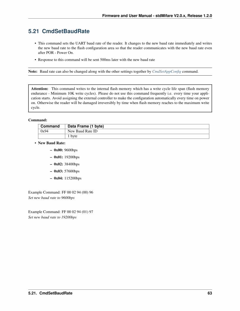
Firmware and User Manual - stdMifare V2.0.x, Release 1.2.0
5.21 CmdSetBaudRate
• This command sets the UART baud rate of the reader. It changes to the new baud rate immediately and writesthe new baud rate to the flash configuration area so that the reader communicates with the new baud rate evenafter POR - Power On.
• Response to this command will be sent 500ms later with the new baud rate
Note: Baud rate can also be changed along with the other settings together by CmdSetAppConfig command.
Attention: This command writes to the internal flash memory which has a write cycle life span (flash memoryendurance - Minimum 10K write cycles). Please do not use this command frequently i.e. every time your appli-cation starts. Avoid assigning the external controller to make the configuration automatically every time on poweron. Otherwise the reader will be damaged irreversibly by time when flash memory reaches to the maximum writecycle.
Command:Command Data Frame (1 byte)0x94 New Baud Rate ID
1 byte
• New Baud Rate:
– 0x00: 9600bps
– 0x01: 19200bps
– 0x02: 38400bps
– 0x03: 57600bps
– 0x04: 115200bps
Example Command: FF 00 02 94 (00) 96Set new baud rate to 9600bps
Example Command: FF 00 02 94 (01) 97Set new baud rate to 19200bps
5.21. CmdSetBaudRate 63
Firmware and User Manual - stdMifare V2.0.x, Release 1.2.0
Response (Status): Response will be sent with the new baud rate. Controller needs to change its baud rate too as wellto get the response successfully.
Response Data Frame (1 byte)0x94 Status Code
1 byte
• Status Code:
– 0x4C (‘L’) : Operation is successful. (Response returns with the new baud rate)
– 0x4E (‘N’) : Operation is failed. (Response returns with the old baud rate)
Example Response (Success): FF 00 02 94 (4C) E2Status Code: 0x4C(‘L’). Operation is successful. Baud rate is changed.
Example Response (Fail): FF 00 02 94 (4E) E4Status Code: 0x4E(‘N’). Operation is failed. Baud rate cannot be changed. Possibly baud rate ID is invalid
64 Chapter 5. stdMifare V2.0.x COMMANDS
Firmware and User Manual - stdMifare V2.0.x, Release 1.2.0
5.22 CmdSetI2CAddress
• This command sets the I2C address in flash configuration area. I2C address is loaded on power on from flashconfiguration area. Thus, a reset is required to use the new I2C address.
• The default I2C address is 0x42 and 7 bit addressing is supported only (I2C address can be up to 0x7F)
Note: I2C address can also be changed along with the other settings together by CmdSetAppConfig command.
Attention: This command writes to the internal flash memory which has a write cycle life span (flash memoryendurance - Minimum 10K write cycles). Please do not use this command frequently i.e. every time your appli-cation starts. Avoid assigning the external controller to make the configuration automatically every time on poweron. Otherwise the reader will be damaged irreversibly by time when flash memory reaches to the maximum writecycle.
Command:Command Data Frame (1 byte)0x9B I2C Slave Address
0 X X X X X X X (7bit)
• I2C Slave Address : 7 bit I2C slave address. Maximum value is 0x7F.
Example Command: FF 00 02 9B (42) DFSet I2C address as 0x42
Response (Status):
Response Data Frame (1 byte)0x9B Status Code
1 byte
• Status Code:
– 0x4C (‘L’) : Operation is successful. Reset is required to take effect.
– 0x4E (‘N’) : Operation is failed.
Example Response (Success): FF 00 02 9B (4C) E9Status Code: 0x4C(‘L’). Operation is successful. Reset is required to take effect.
5.22. CmdSetI2CAddress 65
Firmware and User Manual - stdMifare V2.0.x, Release 1.2.0
5.23 CmdGetI2CAddress
• This command gets the I2C address of the reader.
Note: I2C address can also be retrieved with other settings together by CmdGetAppConfig command.
Command:Command No Data Frame0x9C
• This command has no parameters.
Example Command: FF 00 01 9C 9DGet the I2C address of the reader.
Response:
Response Data Frame (1 byte)0x9C I2C Slave Address
1 byte
• I2C Slave Address: I2C slave address of the reader.
Example Response: FF 00 02 9C (42) E0I2C Slave address of the reader is 0x42
66 Chapter 5. stdMifare V2.0.x COMMANDS
Firmware and User Manual - stdMifare V2.0.x, Release 1.2.0
5.24 CmdPollBuffer
• This command polls the card UID from the reader’s polling buffer. Card UID is added to the polling buffer bythe reader in Auto Mode only when the RS485 and the Polling Mode is activated in device configuration.
• In Auto Mode with RS485 and Polling mode is enabled, when a card is detected, the card UID is placed inpolling buffer temporarily for around 5 seconds so that master can poll it.
• In this mode, RS485 master device can request buffered card UID by asking to all nodes on the RS485 line oneby one. Please see RS485 Modes for polling mode functionality.
Command:Command No Data Frame0xB0
• This command has no parameters.
Example Command: FF 00 01 B0 B1Get card UID, if exists any, from the reader’s polling buffer
5.24. CmdPollBuffer 67
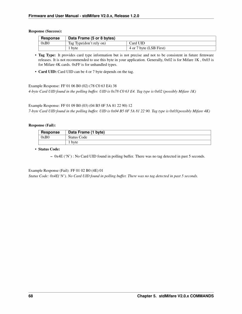
Firmware and User Manual - stdMifare V2.0.x, Release 1.2.0
Response (Success):
Response Data Frame (5 or 8 bytes)0xB0 Tag Type(don’t rely on) Card UID
1 byte 4 or 7 byte (LSB First)
• Tag Type: It provides card type information but is not precise and not to be consistent in future firmwarereleases. It is not recommended to use this byte in your application. Generally, 0x02 is for Mifare 1K , 0x03 isfor Mifare 4K cards. 0xFF is for unhandled types.
• Card UID: Card UID can be 4 or 7 byte depends on the tag.
Example Response: FF 01 06 B0 (02) (78 C0 63 E4) 384-byte Card UID found in the polling buffer. UID is 0x78 C0 63 E4. Tag type is 0x02 (possibly Mifare 1K)
Example Response: FF 01 09 B0 (03) (04 B5 0F 5A 81 22 90) 127-byte Card UID found in the polling buffer. UID is 0x04 B5 0F 5A 81 22 90. Tag type is 0x03(possibly Mifare 4K)
Response (Fail):
Response Data Frame (1 byte)0xB0 Status Code
1 byte
• Status Code:
– 0x4E (‘N’) : No Card UID found in polling buffer. There was no tag detected in past 5 seconds.
Example Response (Fail): FF 01 02 B0 (4E) 01Status Code: 0x4E(‘N’). No Card UID found in polling buffer. There was no tag detected in past 5 seconds.
68 Chapter 5. stdMifare V2.0.x COMMANDS

Firmware and User Manual - stdMifare V2.0.x, Release 1.2.0
5.25 CmdAdvancedOutputDrive
• This command can drive up to 6 outputs, OUT1, OUT2, OUT3(BUZZER), OUT4 and, if configured in deviceconfiguration, SREAD and TAGF pins at the same time with on/off durations and repeat counts.
• Outputs are driven by using an internal state machine, thus the operation is unblocking that means the readercontinue to do its operations and can receive the commands during the output states are being changed.
• It also supports driving the buzzer (OUT3) with 12 pre-configured sound types.
Figure 5.25 CmdAdvancedOutputDrive possible output states of a single output
5.25. CmdAdvancedOutputDrive 69
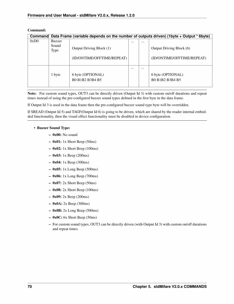
Firmware and User Manual - stdMifare V2.0.x, Release 1.2.0
Command:Command Data Frame (variable depends on the number of outputs driven) (1byte + Output * 6byte)0xD0 Buzzer
SoundType Output Driving Block (1)
(ID/ONTIME/OFFTIME/REPEAT)
... ...
Output Driving Block (6)
(ID/ONTIME/OFFTIME/REPEAT)
1 byte 6 byte (OPTIONAL)B0 B1B2 B3B4 B5
... ...
6 byte (OPTIONAL)B0 B1B2 B3B4 B5
Note: For custom sound types, OUT3 can be directly driven (Output Id 3) with custom on/off durations and repeattimes instead of using the pre-configured buzzer sound types defined in the first byte in the data frame.
If Output Id 3 is used in the data frame then the pre-configured buzzer sound type byte will be overridden.
If SREAD (Output Id 5) and TAGF(Output Id 6) is going to be driven, which are shared by the reader internal embed-ded functionality, then the visual effect functionality must be disabled in device configuration.
• Buzzer Sound Type:
– 0x00: No sound
– 0x01: 1x Short Beep (50ms)
– 0x02: 1x Short Beep (100ms)
– 0x03: 1x Beep (200ms)
– 0x04: 1x Beep (300ms)
– 0x05: 1x Long Beep (500ms)
– 0x06: 1x Long Beep (700ms)
– 0x07: 2x Short Beep (50ms)
– 0x08: 2x Short Beep (100ms)
– 0x09: 2x Beep (200ms)
– 0x0A: 2x Beep (300ms)
– 0x0B: 2x Long Beep (500ms)
– 0x0C: 6x Short Beep (50ms)
– For custom sound types, OUT3 can be directly driven (with Output Id 3) with custom on/off durationsand repeat times.
70 Chapter 5. stdMifare V2.0.x COMMANDS
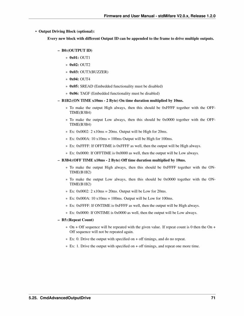
Firmware and User Manual - stdMifare V2.0.x, Release 1.2.0
• Output Driving Block (optional):
Every new block with different Output ID can be appended to the frame to drive multiple outputs.
– B0:(OUTPUT ID)
* 0x01: OUT1
* 0x02: OUT2
* 0x03: OUT3(BUZZER)
* 0x04: OUT4
* 0x05: SREAD (Embedded functionality must be disabled)
* 0x06: TAGF (Embedded functionality must be disabled)
– B1B2:(ON TIME x10ms - 2 Byte) On time duration multiplied by 10ms.
* To make the output High always, then this should be 0xFFFF together with the OFF-TIME(B3B4)
* To make the output Low always, then this should be 0x0000 together with the OFF-TIME(B3B4)
* Ex: 0x0002: 2 x10ms = 20ms. Output will be High for 20ms.
* Ex: 0x000A: 10 x10ms = 100ms Output will be High for 100ms.
* Ex: 0xFFFF: If OFFTIME is 0xFFFF as well, then the output will be High always.
* Ex: 0x0000: If OFFTIME is 0x0000 as well, then the output will be Low always.
– B3B4:(OFF TIME x10ms - 2 Byte) Off time duration multiplied by 10ms.
* To make the output High always, then this should be 0xFFFF together with the ON-TIME(B1B2)
* To make the output Low always, then this should be 0x0000 together with the ON-TIME(B1B2)
* Ex: 0x0002: 2 x10ms = 20ms. Output will be Low for 20ms.
* Ex: 0x000A: 10 x10ms = 100ms. Output will be Low for 100ms.
* Ex: 0xFFFF: If ONTIME is 0xFFFF as well, then the output will be High always.
* Ex: 0x0000: If ONTIME is 0x0000 as well, then the output will be Low always.
– B5:(Repeat Count)
* On + Off sequence will be repeated with the given value. If repeat count is 0 then the On +Off sequence will not be repeated again.
* Ex: 0. Drive the output with specified on + off timings, and do no repeat.
* Ex: 1. Drive the output with specified on + off timings, and repeat one more time.
5.25. CmdAdvancedOutputDrive 71
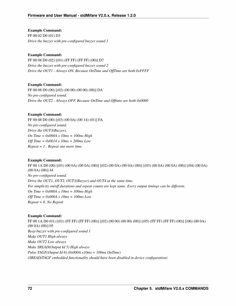
Firmware and User Manual - stdMifare V2.0.x, Release 1.2.0
Example Command:FF 00 02 D0 (01) D3Drive the buzzer with pre-configured buzzer sound 1
Example Command:FF 00 08 D0 (02) [(01) (FF FF) (FF FF) (00)] D7Drive the buzzer with pre-configured buzzer sound 2Drive the OUT1 - Always ON. Because OnTime and OffTime are both 0xFFFF
Example Command:FF 00 08 D0 (00) [(02) (00 00) (00 00) (00)] DANo pre-configured sound.Drive the OUT2 - Always OFF. Because OnTime and Offtime are both 0x0000
Example Command:FF 00 08 D0 (00) [(03) (00 0A) (00 14) (01)] FANo pre-configured sound.Drive the OUT3(Buzzer).On Time = 0x000A x 10ms = 100ms HighOff Time = 0x0014 x 10ms = 200ms LowRepeat = 1 . Repeat one more time.
Example Command:FF 00 1A D0 (00) [(01) (00 0A) (00 0A) (00)] [(02) (00 0A) (00 0A) (00)] [(03) (00 0A) (00 0A) (00)] [(04) (00 0A)(00 0A) (00)] 44No pre-configured sound.Drive the OUT1, OUT2, OUT3(Buzzer) and OUT4 at the same time.For simplicity on/off durations and repeat counts are kept same. Every output timings can be different.On Time = 0x000A x 10ms = 100ms HighOff Time = 0x000A x 10ms = 100ms LowRepeat = 0. No Repeat
Example Command:FF 00 1A D0 (01) [(01) (FF FF) (FF FF) (00)] [(02) (00 00) (00 00) (00)] [(05) (FF FF) (FF FF) (00)] [(06) (00 0A)(00 0A) (00)] 05Beep buzzer with pre-configured sound 1Make OUT1 High alwaysMake OUT2 Low alwaysMake SREAD(Output Id 5) High alwaysPulse TAGF(Output Id 6) (0x000A x10ms = 100ms OnTime)(SREAD/TAGF embedded functionality should have been disabled in device configuration)
72 Chapter 5. stdMifare V2.0.x COMMANDS
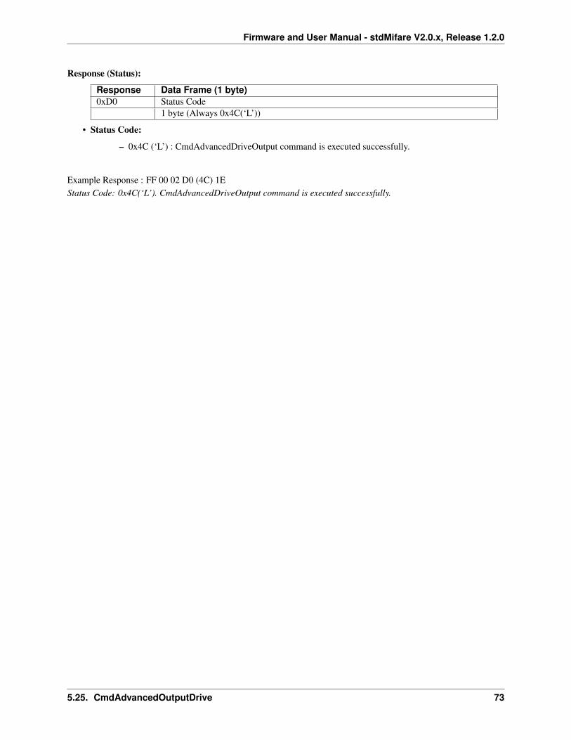
Firmware and User Manual - stdMifare V2.0.x, Release 1.2.0
Response (Status):
Response Data Frame (1 byte)0xD0 Status Code
1 byte (Always 0x4C(‘L’))
• Status Code:
– 0x4C (‘L’) : CmdAdvancedDriveOutput command is executed successfully.
Example Response : FF 00 02 D0 (4C) 1EStatus Code: 0x4C(‘L’). CmdAdvancedDriveOutput command is executed successfully.
5.25. CmdAdvancedOutputDrive 73
Firmware and User Manual - stdMifare V2.0.x, Release 1.2.0
5.26 CmdGetAppConfig
• This command retrieves the device configuration parameters from the reader’s flash memory.
Command:Command Data Frame (1 byte)0xD8 Reserved
1 byte (Use 0x01)
• Reserved: This byte has no effect in stdMifare V2.0.x firmware but it is being preserved in the data frame forbackward compatibility with the UM1.3R 1.1.4 firmware version.
Example Command: FF 00 02 D8 01 DBGet device configuration
Response:
Response Data Frame (15 byte + firmware version string)0xD8 B0 B1 B2 B3 B4 B5 B6 B7 B8 B9 B10 B11 B12 B13 B14 FIRMWARE_VERSION
15 byte (Config Data Frame) Variable(null terminated)
• Config Data Frame - B0 B1 B2 B3 B4 B5 B6 B7 B8 B9 B10 B11 B12 B13 B14
– See Config data frame for details.
• FIRMWARE_VERSION
– Firmware version is reported as ASCII characters with a 0x00 zero termination character at the end.
– Format is “Firmware Caption” + ‘V’(fixed) + 3 Digit Version(fixed) + 0x00(Zero Termination)
– Ex: stdMifareV200 (73 74 64 4D 69 66 61 72 65) (56) (32 30 30) (00)
Example Response : FF 00 1E D8 (02 C0 01 04 01 42 00 00 00 00 00 00 00 00 03) (73 74 64 4D 69 66 61 72 65 5632 30 30 00) 8A
74 Chapter 5. stdMifare V2.0.x COMMANDS
Firmware and User Manual - stdMifare V2.0.x, Release 1.2.0
5.27 CmdSetAppConfig
• This command stores the device configuration parameters in the reader’s flash memory. Reader first sends theresponse and then 200ms later resets itself.
• On startup (POR), the device configuration parameters are loaded from the reader’s flash memory and necessarysettings are initialized.
Command:Command Data Frame (16 byte)0xD9 B0 B1 B2 B3 B4 B5 B6 B7 B8 B9 B10 B11 B12 B13 B14
15 byte (Config Data Frame)
• Config Data Frame - B0 B1 B2 B3 B4 B5 B6 B7 B8 B9 B10 B11 B12 B13 B14
– See Config data frame for details.
Response (Status):
Response Data Frame (1 byte)0xD9 Status Code
1 byte
• Status Code:
– 0x4C (‘L’) : Operation is successful.
– 0x46 (‘F’) : Operation failed.
Example Response : FF 01 02 D9 (4C) 28Status Code: 0x4C(‘L’). Operation is successful.
5.27.1 Config Data Frame
Note:
• Config Data Frame is a 15-byte array both used within the CmdGetAppConfig response frame and CmdSetApp-Config command parameters.
• This 15-byte structure is only valid for stdMifare V2.0.x firmware version. It is not supported by the UM1.3R1.1.4 version or prior versions.
• The previous UM1.3R 1.1.4 firmware version have different configuration data frame and it won’t be mentionedin this document.
• B0 (AppConfigID) (stdMifare V2.0.x has App Config Id = 2)
• B1 (HardwareConfig1) (bit7 bit6 bit5 bit4 bit3 bit2 bit1 bit0)
– bit0 (AutoMode)
* 0: Auto Mode Disabled (Standard Mode)
* 1: Auto Mode Enabled
– bit1 (SendFirmwareVersionOnStartup)
* 0: Do not send firmware version on startup (POR)
5.27. CmdSetAppConfig 75

Firmware and User Manual - stdMifare V2.0.x, Release 1.2.0
* 1: Send firmware version on startup (POR)
– bit2 (SeekForTagOnStartUp)
* 0: Do not seek for tag on startup (POR)
* 1: Seek for tag on startup (POR)
– bit3 (RS485)
* 0: RS485 Disabled. Node Address is not effective
* 1: RS485 Enabled. Node Address is effective
– bit4 (RS485 Polling Mode) RS485 must be enabled for this feature to take effect.
* 0: Polling Mode Disabled. Bidirectional mode will be used (both sides can send data)
* 1: Polling Mode Enabled. Only Master RS485 device can initiate communication.
– bit5 (I2C)
* 0: I2C Disabled.
* 1: I2C Enabled.
– bit6 (BeepOnStartup)
* 0: No buzzer driving on startup (POR)
* 1: OUT3 (Buzzer) pin pulses around ~100ms on reset/POR (Power On)
– bit7 (BeepOnSeekForTagFound)
* 0: No buzzer pin driving on card found for the Seek For Tag operation.
* 1: OUT3 (Buzzer) pin pulses twice with around 50ms periods when a card is detected for theSeek For Tag operation.
• B2 (RS485 Node Address)
– 8-bit RS485 Node address. Node address is used in the Spv1 protocol frame if RS485 is enabled.
• B3 (Auto Mode Configuration) (0 0 0 bit4 bit3 bit2 bit1 bit0)
– bit0 (AutoMode-ASCII)
* 0: Card UID is sent as Spv1 Protocol in Auto Mode
* 1: Card UID is sent as ASCII in Auto Mode
– bit1 (AutoMode-ASCII-Reverse)
* 0: Card UID is not reversed.
* 1: Card UID is reversed and sent as ASCII. Auto Mode (B1.bit0) and ASCII output must beenabled (B3.bit0)
– bit2 (AutoMode-BeepOnTagFound)
* 0: No buzzer pin driving on card found in Auto Mode.
* 1: OUT3 (Buzzer) pin pulses twice with around 50ms periods when a card is detected in AutoMode.
– bit3 (AutoMode-ASCII-CR)
* 0: Do not append Carriage Return character.
76 Chapter 5. stdMifare V2.0.x COMMANDS
Firmware and User Manual - stdMifare V2.0.x, Release 1.2.0
* 1: Append Carriage Return character to the ASCII output. Auto Mode (B1.bit0) and ASCIIoutput must be enabled (B3.bit0)
– bit4 (AutoMode-ASCII-LF)
* 0: Do not append Line Feed character.
* 1: Append Line Feed character to the ASCII output. Auto Mode (B1.bit0) and ASCII outputmust be enabled (B3.bit0)
• B4 (UART Baud Rate)
– Baud rate of the reader.
* 0x00: 9600bps
* 0x01: 19200bps
* 0x02: 38400bps
* 0x03: 57600bps
* 0x04: 115200bps
• B5 (I2C Address)
– 7-bit I2C address.
• B6 (Reserved-UserData1)
– UserData1 is reserved for internal usage. Default Value = 0x00
• B7 (Reserved-UserData2)
– UserData2 is reserved for internal usage. Default Value = 0x00
• B8 B9 B10 (Ascii Header Characters)
– 3 Byte. Up to three ASCII Header (prefix) characters inserted at the beginning of the ASCII CardUID. Auto Mode (B1.bit0) and ASCII output must be enabled (B3.bit0)
– If any of the 3 byte is 0x00 means “no character”
• B11 B12 B13 (Ascii Footer Characters)
– 3 Byte. Up to three ASCII Footer (suffix) characters inserted at the end of the ASCII Card UID. AutoMode (B1.bit0) and ASCII output must be enabled (B3.bit0)
– If any of the 3 byte is 0x00 means “no character”
• B14 (HardwareConfig2) (0 0 0 bit4 bit3 bit2 bit1 bit0)
– bit0 (Pinout Connection Type)
* 0: Type A pin connection
* 1: Type B pin connection
– bit1 (Buzzer Type)
* 0: DC Buzzer. OUT3 is driven as DC pulses.
* 1: PWM Buzzer. OUT3 is driven as square waves (~2730hZ). Only Type B connection supportsPWM Buzzer.
– bit3 bit2 (SREAD/TAGF Functionality)
Please see SREAD/TAGF Functionality section for more details.
* 0 0: Option 0
5.27. CmdSetAppConfig 77
Firmware and User Manual - stdMifare V2.0.x, Release 1.2.0
* 0 1: Option 1
* 1 0: Option 2
* 1 1: Option 3
– bit4 (BeepOnActivateAll)
* 0: No buzzer driving on card found in response to CmdActivateAll command
* 1: OUT3 (Buzzer) pin pulses twice with around 50ms periods when a card is detected inresponse to CmdActivateAll command
78 Chapter 5. stdMifare V2.0.x COMMANDS
CHAPTER
SIX
TRADEMARKS
• MIFARE® is a registered trademark of NXP B.V. and is used under license.
• ARM® and Cortex are registered trademarks of ARM Limited (or its subsidiaries) in the EU and/or elsewhere.All rights reserved.
• NTAG® is a trademark of NXP B.V
79

Firmware and User Manual - stdMifare V2.0.x, Release 1.2.0
80 Chapter 6. TRADEMARKS
CHAPTER
SEVEN
DOCUMENT REVISON HISTORY
Version 1.2.0 (07 Nov 2017)
Corrected the UID byte order in the given examples of card activation (e.g. CmdActivateAll/Idle repsonse). Previousdocument version composes card UID as reversed in the protocol response data frame.
New information is provided about the UID and reverse card UID usage in WARNINGS - Mifare Card Usage section
Version 1.1.0 (02 Nov 2017)
Added new ordering configuration code for SM130 I2C 2.8 compatibility.
Version 1.0.0 (30 Sep 2017)
Initial release.
81
![X10 Tester - · PDF fileX10_Tester.can Page 3 of 128. 151 BYTE hasToSendWriteColumnConfig = 0; 152 BYTE hasToSendWriteColumnDefault = 0; 153 154 BYTE StartLogicControl[6]; 155 BYTE](https://img.pdfslide.us/doc/110x75/5aa9f1037f8b9a9a188d968e/x10-tester-page-3-of-128-151-byte-hastosendwritecolumnconfig-0-152-byte-hastosendwritecolumndefault.jpg)