Embed Size (px)
Citation preview
1
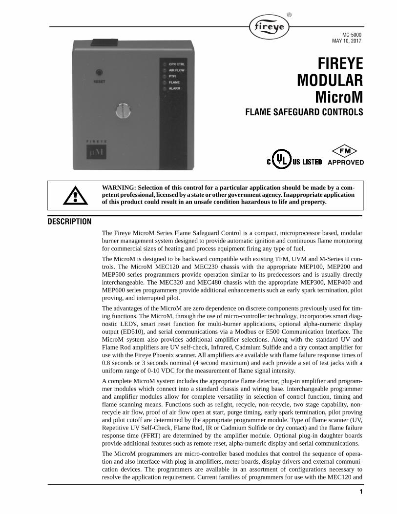
FIREYEMODULAR
MicroMFLAME SAFEGUARD CONTROLS
WARNING: Selection of this control for a particular application should be made by a com-petent professional, licensed by a state or other government agency. Inappropriate applicationof this product could result in an unsafe condition hazardous to life and property.
DESCRIPTIONThe Fireye MicroM Series Flame Safeguard Control is a compact, microprocessor based, modularburner management system designed to provide automatic ignition and continuous flame monitoringfor commercial sizes of heating and process equipment firing any type of fuel.
The MicroM is designed to be backward compatible with existing TFM, UVM and M-Series II con-trols. The MicroM MEC120 and MEC230 chassis with the appropriate MEP100, MEP200 andMEP500 series programmers provide operation similar to its predecessors and is usually directlyinterchangeable. The MEC320 and MEC480 chassis with the appropriate MEP300, MEP400 andMEP600 series programmers provide additional enhancements such as early spark termination, pilotproving, and interrupted pilot.
The advantages of the MicroM are zero dependence on discrete components previously used for tim-ing functions. The MicroM, through the use of micro-controller technology, incorporates smart diag-nostic LED's, smart reset function for multi-burner applications, optional alpha-numeric displayoutput (ED510), and serial communications via a Modbus or E500 Communication Interface. TheMicroM system also provides additional amplifier selections. Along with the standard UV andFlame Rod amplifiers are UV self-check, Infrared, Cadmium Sulfide and a dry contact amplifier foruse with the Fireye Phoenix scanner. All amplifiers are available with flame failure response times of0.8 seconds or 3 seconds nominal (4 second maximum) and each provide a set of test jacks with auniform range of 0-10 VDC for the measurement of flame signal intensity.
A complete MicroM system includes the appropriate flame detector, plug-in amplifier and program-mer modules which connect into a standard chassis and wiring base. Interchangeable programmerand amplifier modules allow for complete versatility in selection of control function, timing andflame scanning means. Functions such as relight, recycle, non-recycle, two stage capability, non-recycle air flow, proof of air flow open at start, purge timing, early spark termination, pilot provingand pilot cutoff are determined by the appropriate programmer module. Type of flame scanner (UV,Repetitive UV Self-Check, Flame Rod, IR or Cadmium Sulfide or dry contact) and the flame failureresponse time (FFRT) are determined by the amplifier module. Optional plug-in daughter boardsprovide additional features such as remote reset, alpha-numeric display and serial communications.
The MicroM programmers are micro-controller based modules that control the sequence of opera-tion and also interface with plug-in amplifiers, meter boards, display drivers and external communi-cation devices. The programmers are available in an assortment of configurations necessary toresolve the application requirement. Current families of programmers for use with the MEC120 and
MC-5000MAY 10, 2017
APPROVED
2
MEC230 type chassis include the MEP100, MEP 200 and MEP500 series. Programmers for use withthe MEC320 and MEC480 type chassis include the MEP300, MEP400 and MEP600 series.
Some programmer modules are equipped with a series of dipswitches to select Purge Timing, PilotTrial for Ignition (PTFI) timing, Proof of Air flow open at start, Post Purge, Recycle and Non-Recy-cle operation. LED indicators on the programmer modules indicate the current operating status of thecontrol and during a lockout condition displays the fault as a coded sequence, simplifying the trou-bleshooting of a shutdown.
In the event of pilot ignition failure, or following a safety shutdown, the control locks out, activatingan alarm circuit and displays the cause of lockout on the integrated LED’s and on the optional ED510display. Unless otherwise specified, manual reset is required. Remote reset is available on theMEC120R, MEC120RC, MEC320RD, MEC230RC, MEC320R, MEC320RC and MEC320RDchassis. A detailed description of the various programmer, amplifier and chassis modules is foundlater in this document. A “run-check” switch, provided to assist in testing size, position and stabiliza-tion of the pilot, is provided on some specific models and all MEP500 and MEP600 series program-mers.
Modular MicroM controls incorporate a safety checking circuit that is operative on each start. Ifflame (real or simulated) is detected prior to a start or during purge, the fuel valves will not be ener-gized and the unit will lock out.
The modular MicroM controls use the same wiring base as the Fireye UVM, TFM and M- Series IIcontrols and are designed to be interchangeable with most models with little or no rewiring. SeeINSTALLATION OF CONTROL, SCANNERS AND FLAME DETECTORS (page 8 and 47) fortemperature and wiring requirements.
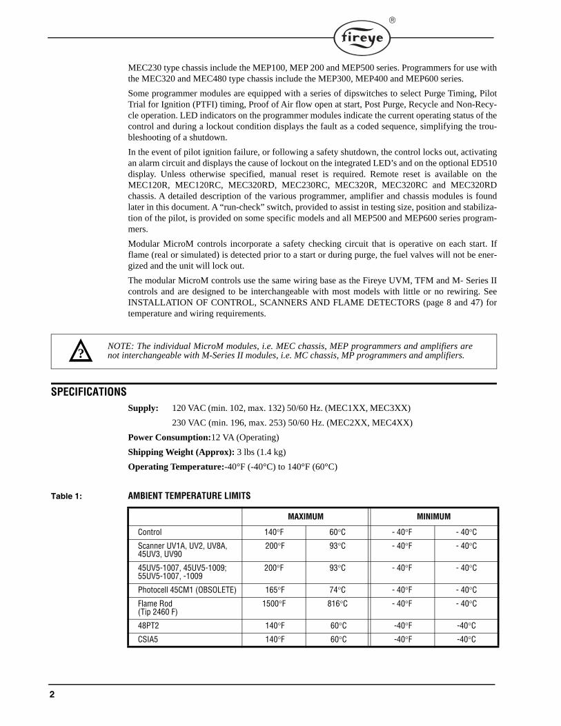
SPECIFICATIONSSupply: 120 VAC (min. 102, max. 132) 50/60 Hz. (MEC1XX, MEC3XX)
230 VAC (min. 196, max. 253) 50/60 Hz. (MEC2XX, MEC4XX)
Power Consumption:12 VA (Operating)
Shipping Weight (Approx): 3 lbs (1.4 kg)
Operating Temperature:-40°F (-40°C) to 140°F (60°C)
Table 1: AMBIENT TEMPERATURE LIMITS
MAXIMUM MINIMUM
Control 140°F 60°C - 40°F - 40°C
Scanner UV1A, UV2, UV8A, 45UV3, UV90
200°F 93°C - 40°F - 40°C
45UV5-1007, 45UV5-1009;55UV5-1007, -1009
200°F 93°C - 40°F - 40°C
Photocell 45CM1 (OBSOLETE) 165°F 74°C - 40°F - 40°C
Flame Rod(Tip 2460 F)
1500°F 816°C - 40°F - 40°C
48PT2 140°F 60°C -40°F -40°C
CSIA5 140°F 60°C -40°F -40°C
NOTE: The individual MicroM modules, i.e. MEC chassis, MEP programmers and amplifiers arenot interchangeable with M-Series II modules, i.e. MC chassis, MP programmers and amplifiers.?
3
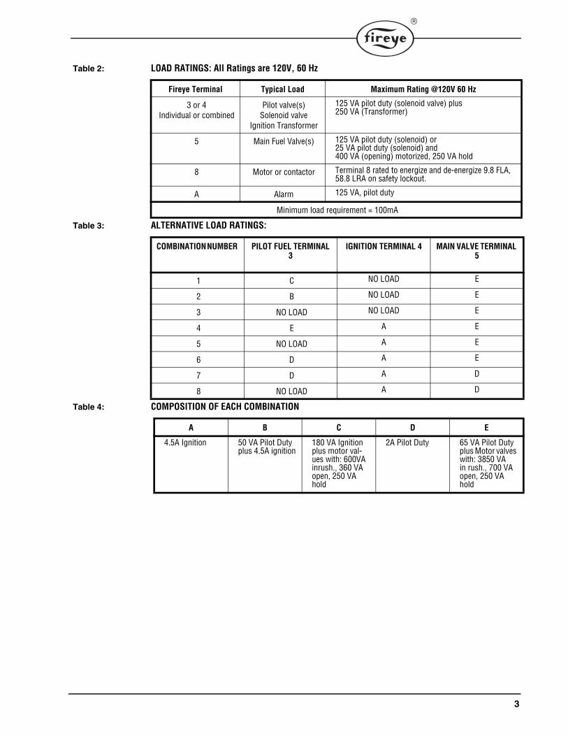
Table 2: LOAD RATINGS: All Ratings are 120V, 60 Hz
Table 3: ALTERNATIVE LOAD RATINGS:
Table 4: COMPOSITION OF EACH COMBINATION
Fireye Terminal Typical Load Maximum Rating @120V 60 Hz
3 or 4Individual or combined
Pilot valve(s)Solenoid valve
Ignition Transformer
125 VA pilot duty (solenoid valve) plus250 VA (Transformer)
5 Main Fuel Valve(s) 125 VA pilot duty (solenoid) or25 VA pilot duty (solenoid) and400 VA (opening) motorized, 250 VA hold
8 Motor or contactor Terminal 8 rated to energize and de-energize 9.8 FLA, 58.8 LRA on safety lockout.
A Alarm 125 VA, pilot duty
Minimum load requirement = 100mA
COMBINATION NUMBER PILOT FUEL TERMINAL 3
IGNITION TERMINAL 4 MAIN VALVE TERMINAL 5
1 C NO LOAD E
2 B NO LOAD E
3 NO LOAD NO LOAD E
4 E A E
5 NO LOAD A E
6 D A E
7 D A D
8 NO LOAD A D
A B C D E
4.5A Ignition 50 VA Pilot Duty plus 4.5A ignition
180 VA Ignition plus motor val-ues with: 600VA inrush., 360 VA open, 250 VA hold
2A Pilot Duty 65 VA Pilot Duty plus Motor valves with: 3850 VA in rush., 700 VA open, 250 VA hold
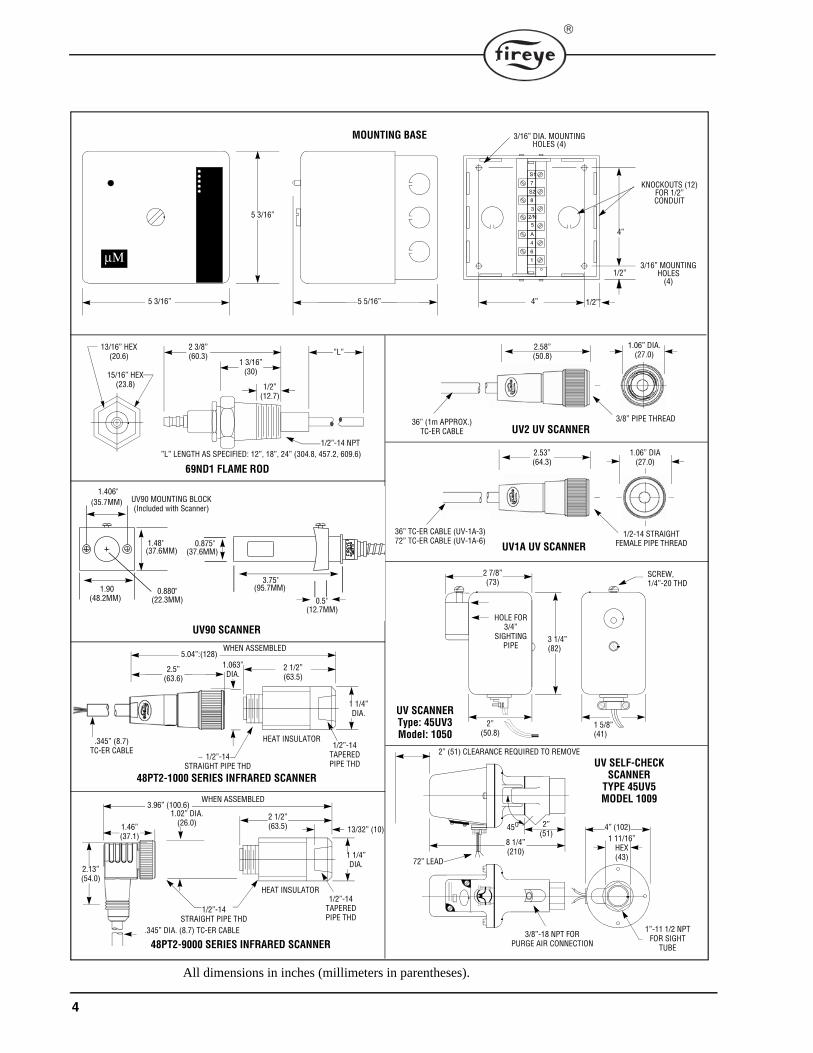
4
HOLE FOR3/4”
SIGHTINGPIPE
SCREW,1/4”-20 THD
2” (51) CLEARANCE REQUIRED TO REMOVE
2”(51)
1/2”-14STRAIGHT PIPE THD
8 1/4”(210)
45O
3/8”-18 NPT FORPURGE AIR CONNECTION
4” (102)1 11/16”
HEX(43)
1”-11 1/2 NPTFOR SIGHT
TUBE
UV2 UV SCANNER
UV SELF-CHECKSCANNER
TYPE 45UV5MODEL 1009
UV1A UV SCANNER
72” LEAD
2 7/8”(73)
2”(50.8)
1 5/8”(41)
3 1/4”(82)
UV SCANNERType: 45UV3Model: 1050
2 3/8”(60.3)
1 3/16”(30)
1/2”(12.7)
”L”
1/2”-14 NPT
13/16” HEX(20.6)
15/16” HEX(23.8)
”L” LENGTH AS SPECIFIED: 12”, 18”, 24” (304.8, 457.2, 609.6)
69ND1 FLAME ROD
2 1/2”(63.5)
5.04”:(128)WHEN ASSEMBLED
1 1/4” DIA.
1.063” DIA.
HEAT INSULATOR.345” (8.7) TC-ER CABLE
1/2”-14TAPEREDPIPE THD
1/2”-14STRAIGHT PIPE THD
48PT2-1000 SERIES INFRARED SCANNER
2 1/2”(63.5)
3.96” (100.6)WHEN ASSEMBLED
1 1/4” DIA.
1.02” DIA.(26.0)
HEAT INSULATOR
.345” DIA. (8.7) TC-ER CABLE
1/2”-14TAPEREDPIPE THD
2.13”(54.0)
1.46”(37.1)
13/32” (10)
48PT2-9000 SERIES INFRARED SCANNER
UV90 SCANNER
5 3/16”
5 3/16”
MOUNTING BASE
5 5/16”
4”
4” 1/2”’
1/2”
3/16” DIA. MOUNTING HOLES (4)
KNOCKOUTS (12)FOR 1/2”CONDUIT
μΜ
All dimensions in inches (millimeters in parentheses).
S1
7
S2
8
32/N5
A
4
1
6
3/16” MOUNTING HOLES
(4)
0.880"(22.3MM)
1.90(48.2MM)
1.406"(35.7MM)
1.48"(37.6MM)
0.875"(37.6MM)
3.75"(95.7MM)
0.5"(12.7MM)
UV90 MOUNTING BLOCK(Included with Scanner)
2.58”(50.8)
36” (1m APPROX.)TC-ER CABLE
3/8” PIPE THREAD
1.06” DIA.(27.0)
2.53”(64.3)
1/2-14 STRAIGHTFEMALE PIPE THREAD
1.06” DIA(27.0)
36” TC-ER CABLE (UV-1A-3)72” TC-ER CABLE (UV-1A-6)
2.5”(63.6)
5
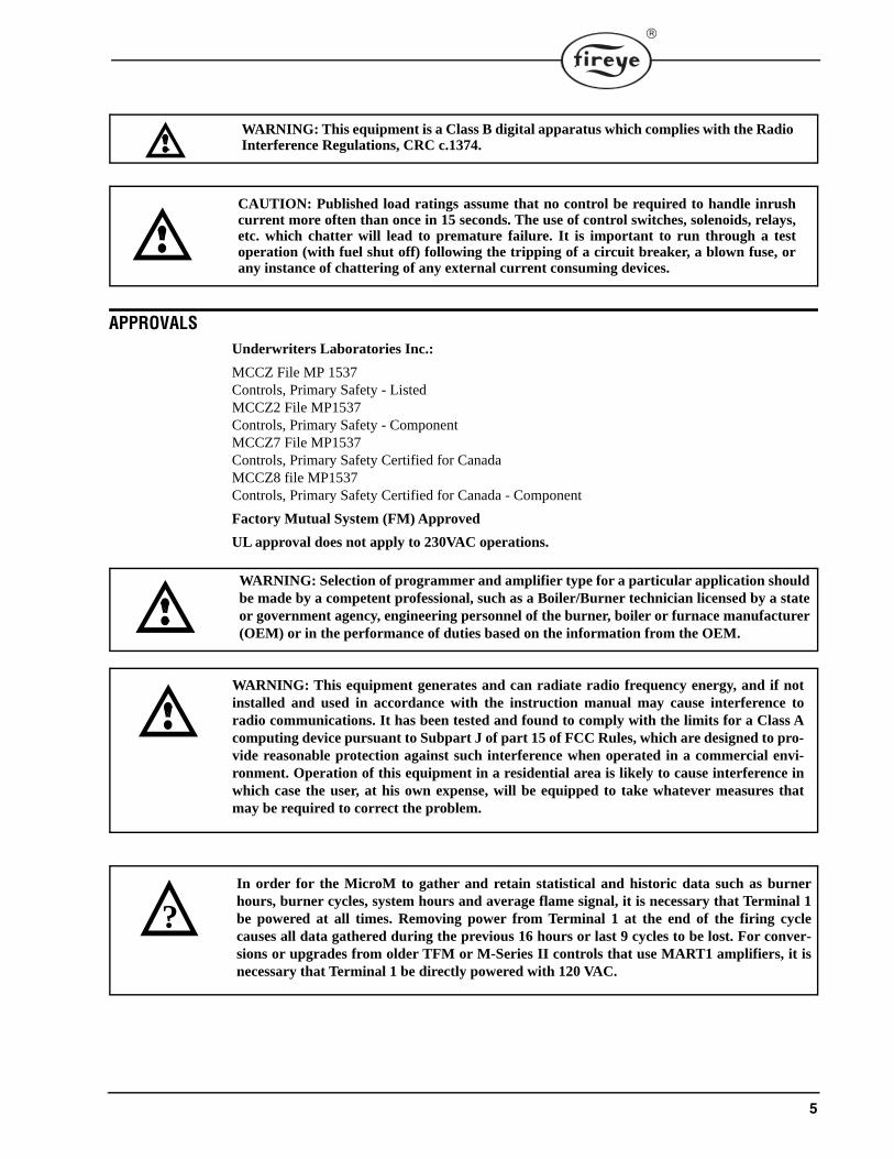
APPROVALSUnderwriters Laboratories Inc.:
MCCZ File MP 1537Controls, Primary Safety - ListedMCCZ2 File MP1537Controls, Primary Safety - ComponentMCCZ7 File MP1537Controls, Primary Safety Certified for CanadaMCCZ8 file MP1537Controls, Primary Safety Certified for Canada - Component
Factory Mutual System (FM) Approved
UL approval does not apply to 230VAC operations.
WARNING: This equipment is a Class B digital apparatus which complies with the RadioInterference Regulations, CRC c.1374.
CAUTION: Published load ratings assume that no control be required to handle inrushcurrent more often than once in 15 seconds. The use of control switches, solenoids, relays,etc. which chatter will lead to premature failure. It is important to run through a testoperation (with fuel shut off) following the tripping of a circuit breaker, a blown fuse, orany instance of chattering of any external current consuming devices.
WARNING: Selection of programmer and amplifier type for a particular application shouldbe made by a competent professional, such as a Boiler/Burner technician licensed by a stateor government agency, engineering personnel of the burner, boiler or furnace manufacturer(OEM) or in the performance of duties based on the information from the OEM.
WARNING: This equipment generates and can radiate radio frequency energy, and if notinstalled and used in accordance with the instruction manual may cause interference toradio communications. It has been tested and found to comply with the limits for a Class Acomputing device pursuant to Subpart J of part 15 of FCC Rules, which are designed to pro-vide reasonable protection against such interference when operated in a commercial envi-ronment. Operation of this equipment in a residential area is likely to cause interference inwhich case the user, at his own expense, will be equipped to take whatever measures thatmay be required to correct the problem.
In order for the MicroM to gather and retain statistical and historic data such as burnerhours, burner cycles, system hours and average flame signal, it is necessary that Terminal 1be powered at all times. Removing power from Terminal 1 at the end of the firing cyclecauses all data gathered during the previous 16 hours or last 9 cycles to be lost. For conver-sions or upgrades from older TFM or M-Series II controls that use MART1 amplifiers, it isnecessary that Terminal 1 be directly powered with 120 VAC.
?
6
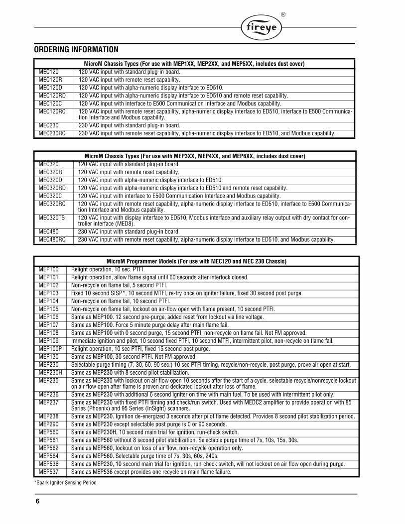
ORDERING INFORMATION
*Spark Igniter Sensing Period
MicroM Chassis Types (For use with MEP1XX, MEP2XX, and MEP5XX, includes dust cover)MEC120 120 VAC input with standard plug-in board.MEC120R 120 VAC input with remote reset capability.MEC120D 120 VAC input with alpha-numeric display interface to ED510.MEC120RD 120 VAC input with alpha-numeric display interface to ED510 and remote reset capability.MEC120C 120 VAC input with interface to E500 Communication Interface and Modbus capability.MEC120RC 120 VAC input with remote reset capability, alpha-numeric display interface to ED510, interface to E500 Communica-
tion Interface and Modbus capability.MEC230 230 VAC input with standard plug-in board.MEC230RC 230 VAC input with remote reset capability, alpha-numeric display interface to ED510, and Modbus capability.
MicroM Chassis Types (For use with MEP3XX, MEP4XX, and MEP6XX, includes dust cover)MEC320 120 VAC input with standard plug-in board.MEC320R 120 VAC input with remote reset capability.MEC320D 120 VAC input with alpha-numeric display interface to ED510.MEC320RD 120 VAC input with alpha-numeric display interface to ED510 and remote reset capability.MEC320C 120 VAC input with interface to E500 Communication Interface and Modbus capability.MEC320RC 120 VAC input with remote reset capability, alpha-numeric display interface to ED510, interface to E500 Communica-
tion Interface and Modbus capability.MEC320TS 120 VAC input with display interface to ED510, Modbus interface and auxiliary relay output with dry contact for con-
troller interface (MED8).MEC480 230 VAC input with standard plug-in board.MEC480RC 230 VAC input with remote reset capability, alpha-numeric display interface to ED510, and Modbus capability.
MicroM Programmer Models (For use with MEC120 and MEC 230 Chassis)MEP100 Relight operation, 10 sec. PTFI.MEP101 Relight operation, allow flame signal until 60 seconds after interlock closed.MEP102 Non-recycle on flame fail, 5 second PTFI.MEP103 Fixed 10 second SISP*, 10 second MTFI, re-try once on igniter failure, fixed 30 second post purge.MEP104 Non-recycle on flame fail, 10 second PTFI.MEP105 Non-recycle on flame fail, lockout on air-flow open with flame present, 10 second PTFI.MEP106 Same as MEP100. 12 second pre-purge, added reset from lockout via line voltage.MEP107 Same as MEP100. Force 5 minute purge delay after main flame fail.MEP108 Same as MEP100 with 0 second purge, 15 second PTFI, non-recycle on flame fail. Not FM approved.MEP109 Immediate ignition and pilot, 10 second fixed PTFI, 10 second MTFI, intermittent pilot, non-recycle on flame fail.MEP100P Relight operation, 10 sec PTFI, fixed 15 second post purge.MEP130 Same as MEP100, 30 second PTFI. Not FM approved.MEP230 Selectable purge timing (7, 30, 60, 90 sec.) 10 sec PTFI timing, recycle/non-recycle, post purge, prove air open at start.MEP230H Same as MEP230 with 8 second pilot stabilization.MEP235 Same as MEP230 with lockout on air flow open 10 seconds after the start of a cycle, selectable recycle/nonrecycle lockout
on air flow open after flame is proven and dedicated lockout after loss of flame.MEP236 Same as MEP230 with additional 6 second igniter on time with main fuel. To be used with intermittent pilot only.MEP237 Same as MEP230 with fixed PTFI timing and check/run switch. Used with MEDC2 amplifier to provide operation with 85
Series (Phoenix) and 95 Series (InSight) scanners.MEP238 Same as MEP230. Ignition de-energized 3 seconds after pilot flame detected. Provides 8 second pilot stabilization period. MEP290 Same as MEP230 except selectable post purge is 0 or 90 seconds.MEP560 Same as MEP230H, 10 second main trial for ignition, run-check switch.MEP561 Same as MEP560 without 8 second pilot stabilization. Selectable purge time of 7s, 10s, 15s, 30s.MEP562 Same as MEP560, lockout on loss of air flow, non-recycle operation only.MEP564 Same as MEP560. Selectable purge time of 7s, 30s, 60s, 240s.MEP536 Same as MEP230, 10 second main trial for ignition, run-check switch, will not lockout on air flow open during purge.MEP537 Same as MEP536 except provides one recycle on main flame failure.
7
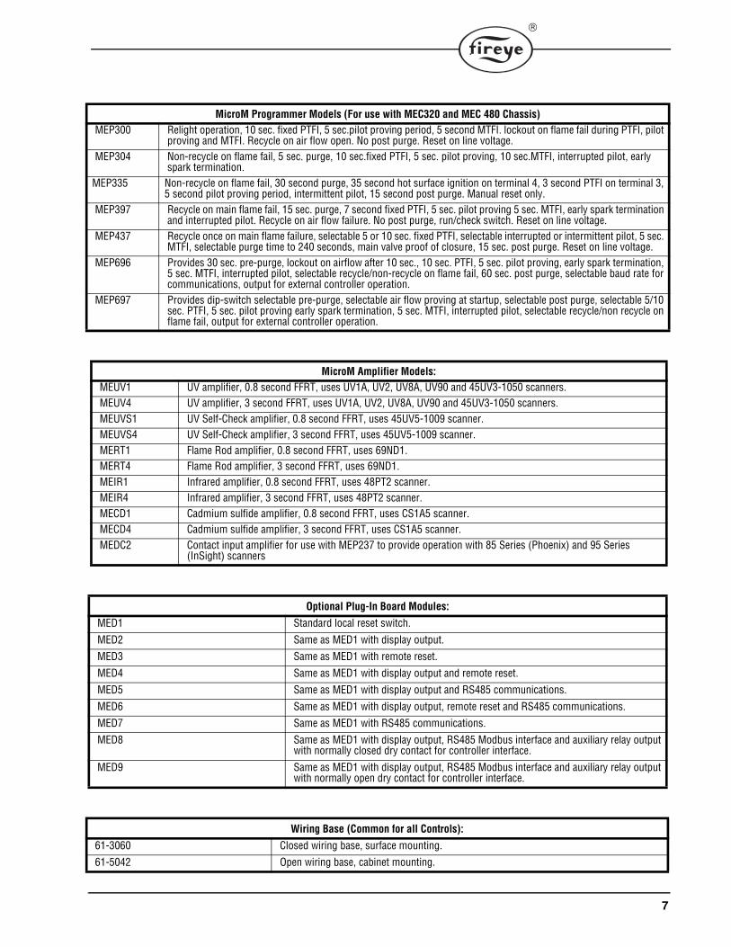
MicroM Programmer Models (For use with MEC320 and MEC 480 Chassis)MEP300 Relight operation, 10 sec. fixed PTFI, 5 sec.pilot proving period, 5 second MTFI. lockout on flame fail during PTFI, pilot
proving and MTFI. Recycle on air flow open. No post purge. Reset on line voltage.MEP304 Non-recycle on flame fail, 5 sec. purge, 10 sec.fixed PTFI, 5 sec. pilot proving, 10 sec.MTFI, interrupted pilot, early
spark termination.MEP335 Non-recycle on flame fail, 30 second purge, 35 second hot surface ignition on terminal 4, 3 second PTFI on terminal 3,
5 second pilot proving period, intermittent pilot, 15 second post purge. Manual reset only.MEP397 Recycle on main flame fail, 15 sec. purge, 7 second fixed PTFI, 5 sec. pilot proving 5 sec. MTFI, early spark termination
and interrupted pilot. Recycle on air flow failure. No post purge, run/check switch. Reset on line voltage.MEP437 Recycle once on main flame failure, selectable 5 or 10 sec. fixed PTFI, selectable interrupted or intermittent pilot, 5 sec.
MTFI, selectable purge time to 240 seconds, main valve proof of closure, 15 sec. post purge. Reset on line voltage.MEP696 Provides 30 sec. pre-purge, lockout on airflow after 10 sec., 10 sec. PTFI, 5 sec. pilot proving, early spark termination,
5 sec. MTFI, interrupted pilot, selectable recycle/non-recycle on flame fail, 60 sec. post purge, selectable baud rate for communications, output for external controller operation.
MEP697 Provides dip-switch selectable pre-purge, selectable air flow proving at startup, selectable post purge, selectable 5/10 sec. PTFI, 5 sec. pilot proving early spark termination, 5 sec. MTFI, interrupted pilot, selectable recycle/non recycle on flame fail, output for external controller operation.
MicroM Amplifier Models:MEUV1 UV amplifier, 0.8 second FFRT, uses UV1A, UV2, UV8A, UV90 and 45UV3-1050 scanners.MEUV4 UV amplifier, 3 second FFRT, uses UV1A, UV2, UV8A, UV90 and 45UV3-1050 scanners.MEUVS1 UV Self-Check amplifier, 0.8 second FFRT, uses 45UV5-1009 scanner.MEUVS4 UV Self-Check amplifier, 3 second FFRT, uses 45UV5-1009 scanner.MERT1 Flame Rod amplifier, 0.8 second FFRT, uses 69ND1.MERT4 Flame Rod amplifier, 3 second FFRT, uses 69ND1.MEIR1 Infrared amplifier, 0.8 second FFRT, uses 48PT2 scanner.MEIR4 Infrared amplifier, 3 second FFRT, uses 48PT2 scanner.MECD1 Cadmium sulfide amplifier, 0.8 second FFRT, uses CS1A5 scanner.MECD4 Cadmium sulfide amplifier, 3 second FFRT, uses CS1A5 scanner.MEDC2 Contact input amplifier for use with MEP237 to provide operation with 85 Series (Phoenix) and 95 Series
(InSight) scanners
Optional Plug-In Board Modules:MED1 Standard local reset switch.
MED2 Same as MED1 with display output.MED3 Same as MED1 with remote reset.
MED4 Same as MED1 with display output and remote reset.MED5 Same as MED1 with display output and RS485 communications.
MED6 Same as MED1 with display output, remote reset and RS485 communications.MED7 Same as MED1 with RS485 communications.MED8 Same as MED1 with display output, RS485 Modbus interface and auxiliary relay output
with normally closed dry contact for controller interface.
MED9 Same as MED1 with display output, RS485 Modbus interface and auxiliary relay output with normally open dry contact for controller interface.
Wiring Base (Common for all Controls):61-3060 Closed wiring base, surface mounting.61-5042 Open wiring base, cabinet mounting.
8
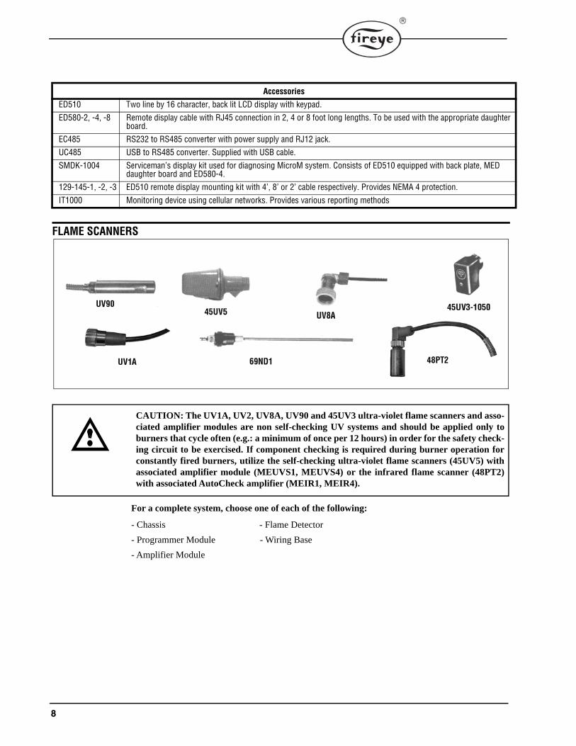
FLAME SCANNERS
For a complete system, choose one of each of the following:
- Chassis - Flame Detector
- Programmer Module - Wiring Base
- Amplifier Module
AccessoriesED510 Two line by 16 character, back lit LCD display with keypad.
ED580-2, -4, -8 Remote display cable with RJ45 connection in 2, 4 or 8 foot long lengths. To be used with the appropriate daughter board.
EC485 RS232 to RS485 converter with power supply and RJ12 jack.UC485 USB to RS485 converter. Supplied with USB cable.
SMDK-1004 Serviceman’s display kit used for diagnosing MicroM system. Consists of ED510 equipped with back plate, MED daughter board and ED580-4.
129-145-1, -2, -3 ED510 remote display mounting kit with 4’, 8’ or 2’ cable respectively. Provides NEMA 4 protection.
IT1000 Monitoring device using cellular networks. Provides various reporting methods
CAUTION: The UV1A, UV2, UV8A, UV90 and 45UV3 ultra-violet flame scanners and asso-ciated amplifier modules are non self-checking UV systems and should be applied only toburners that cycle often (e.g.: a minimum of once per 12 hours) in order for the safety check-ing circuit to be exercised. If component checking is required during burner operation forconstantly fired burners, utilize the self-checking ultra-violet flame scanners (45UV5) withassociated amplifier module (MEUVS1, MEUVS4) or the infrared flame scanner (48PT2)with associated AutoCheck amplifier (MEIR1, MEIR4).
9
INSTALLATION OF CONTROL, SCANNERS AND FLAME DETECTORS
Wiring Base
Mount the wiring base on the burner or on a panel. The location should be free from excessive vibra-tion and within the specified ambient temperature rating. The base may be mounted in any angularposition.
All wiring should comply with applicable electrical codes, regulations and local ordinances. Usemoisture resistant wire suitable for at least 90 degrees C. Good electrical wiring practice should befollowed to ensure an adequate ground system. Refer to Fireye Service Note SN-100 separately andGeneral Grounding Rules later in this document for grounding methods.
A good ground system should be provided to minimize the effects of AC quality problems. A prop-erly designed ground system meeting all the safety requirements will ensure that any AC voltagequality problems, such as spikes, surges and impulses have a low impedance path to ground. A lowimpedance path to ground is required to ensure that large currents involved with any surge voltageswill follow the desired path in preference to alternative paths, where extensive damage may occur toequipment.
Circuit recommendations are found on pages 38 through 43. Consult the factory for assistance withnon-standard applications.
WARNING: Installer must be trained and qualified. Follow the burner manufacturer’sinstructions, if supplied. Otherwise, proceed as follows:
WARNING: Controls require safety limits utilizing isolated mechanical contacts. Electronic limit switches may cause erratic operation and should be avoided.
Care must be taken to NOT route the high energy ignition wire in close proxim-ity to the flame sensor wiring, particularly when using MERT amplifier.
10
INSTALLING THE PROGRAMMER AND AMPLIFIER MODULES
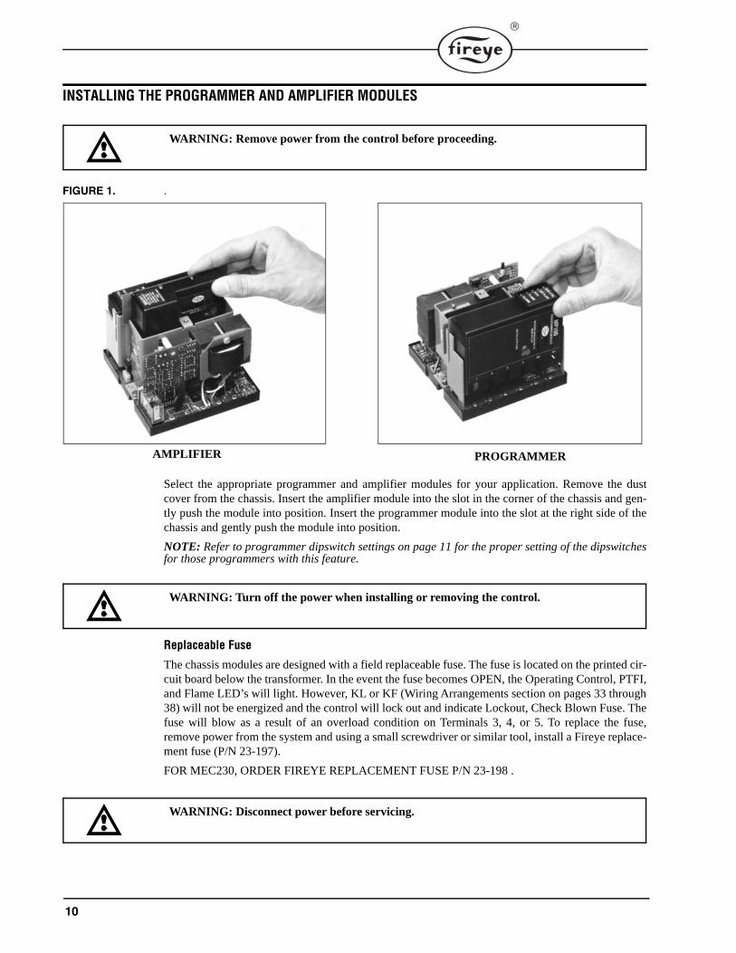
FIGURE 1. .
Select the appropriate programmer and amplifier modules for your application. Remove the dustcover from the chassis. Insert the amplifier module into the slot in the corner of the chassis and gen-tly push the module into position. Insert the programmer module into the slot at the right side of thechassis and gently push the module into position.
NOTE: Refer to programmer dipswitch settings on page 11 for the proper setting of the dipswitchesfor those programmers with this feature.
Replaceable Fuse
The chassis modules are designed with a field replaceable fuse. The fuse is located on the printed cir-cuit board below the transformer. In the event the fuse becomes OPEN, the Operating Control, PTFI,and Flame LED’s will light. However, KL or KF (Wiring Arrangements section on pages 33 through38) will not be energized and the control will lock out and indicate Lockout, Check Blown Fuse. Thefuse will blow as a result of an overload condition on Terminals 3, 4, or 5. To replace the fuse,remove power from the system and using a small screwdriver or similar tool, install a Fireye replace-ment fuse (P/N 23-197).
FOR MEC230, ORDER FIREYE REPLACEMENT FUSE P/N 23-198 .
WARNING: Remove power from the control before proceeding.
PROGRAMMERAMPLIFIER
WARNING: Turn off the power when installing or removing the control.
WARNING: Disconnect power before servicing.
11
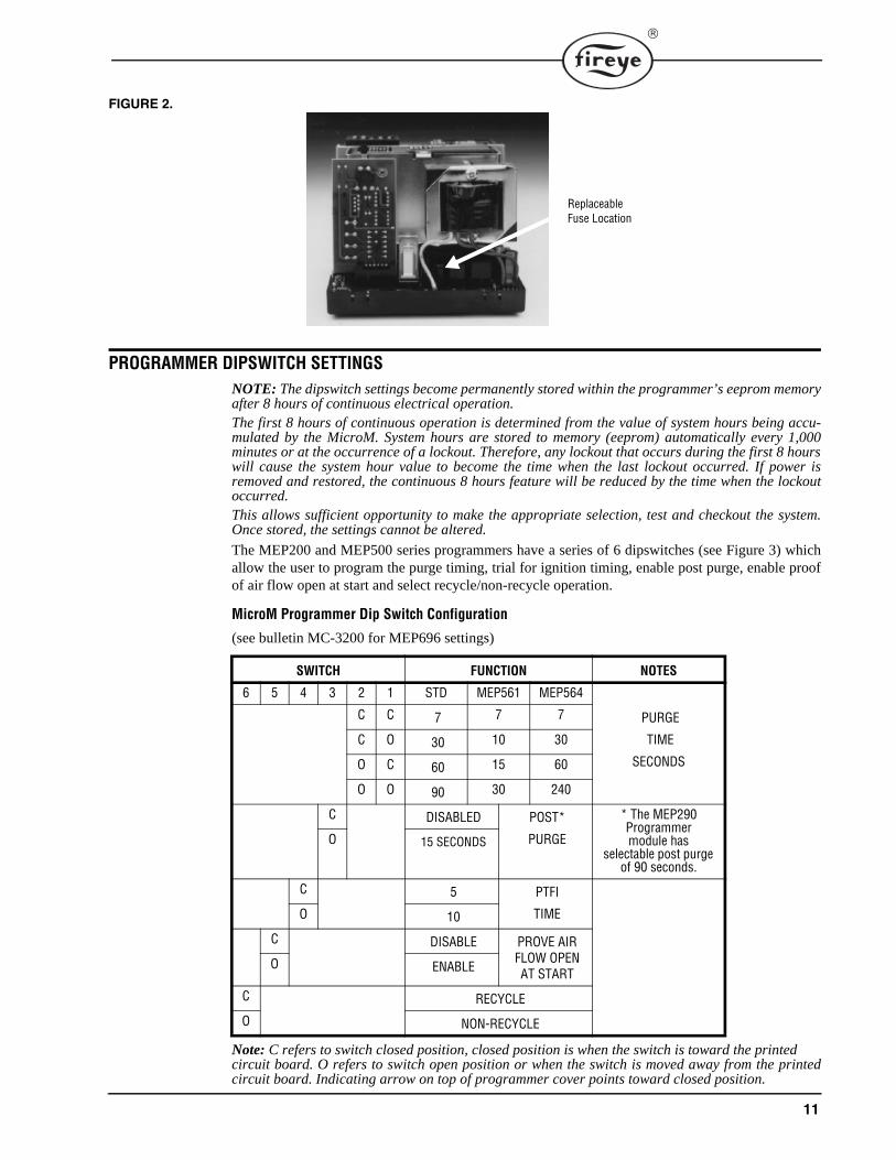
FIGURE 2.
PROGRAMMER DIPSWITCH SETTINGSNOTE: The dipswitch settings become permanently stored within the programmer’s eeprom memoryafter 8 hours of continuous electrical operation. The first 8 hours of continuous operation is determined from the value of system hours being accu-mulated by the MicroM. System hours are stored to memory (eeprom) automatically every 1,000minutes or at the occurrence of a lockout. Therefore, any lockout that occurs during the first 8 hourswill cause the system hour value to become the time when the last lockout occurred. If power isremoved and restored, the continuous 8 hours feature will be reduced by the time when the lockoutoccurred. This allows sufficient opportunity to make the appropriate selection, test and checkout the system.Once stored, the settings cannot be altered.
The MEP200 and MEP500 series programmers have a series of 6 dipswitches (see Figure 3) whichallow the user to program the purge timing, trial for ignition timing, enable post purge, enable proofof air flow open at start and select recycle/non-recycle operation.
MicroM Programmer Dip Switch Configuration
(see bulletin MC-3200 for MEP696 settings)
Note: C refers to switch closed position, closed position is when the switch is toward the printed circuit board. O refers to switch open position or when the switch is moved away from the printedcircuit board. Indicating arrow on top of programmer cover points toward closed position.
SWITCH FUNCTION NOTES
6 5 4 3 2 1 STD MEP561 MEP564
PURGE
TIME
SECONDS
C C 7 7 7
C O 30 10 30
O C 60 15 60
O O 90 30 240
C DISABLED POST*
PURGE
* The MEP290 Programmer module has
selectable post purge of 90 seconds.
O 15 SECONDS
C 5 PTFI
TIMEO 10
C DISABLE PROVE AIR FLOW OPEN AT START
O ENABLE
C RECYCLE
O NON-RECYCLE
ReplaceableFuse Location
12
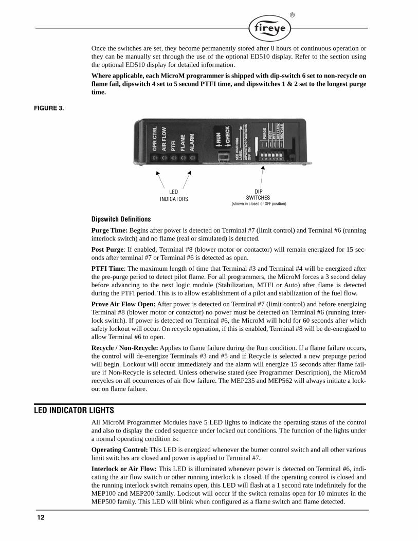
Once the switches are set, they become permanently stored after 8 hours of continuous operation orthey can be manually set through the use of the optional ED510 display. Refer to the section usingthe optional ED510 display for detailed information.
Where applicable, each MicroM programmer is shipped with dip-switch 6 set to non-recycle onflame fail, dipswitch 4 set to 5 second PTFI time, and dipswitches 1 & 2 set to the longest purgetime.
FIGURE 3.
Dipswitch Definitions
Purge Time: Begins after power is detected on Terminal #7 (limit control) and Terminal #6 (runninginterlock switch) and no flame (real or simulated) is detected.
Post Purge: If enabled, Terminal #8 (blower motor or contactor) will remain energized for 15 sec-onds after terminal #7 or Terminal #6 is detected as open.
PTFI Time: The maximum length of time that Terminal #3 and Terminal #4 will be energized afterthe pre-purge period to detect pilot flame. For all programmers, the MicroM forces a 3 second delaybefore advancing to the next logic module (Stabilization, MTFI or Auto) after flame is detectedduring the PTFI period. This is to allow establishment of a pilot and stabilization of the fuel flow.
Prove Air Flow Open: After power is detected on Terminal #7 (limit control) and before energizingTerminal #8 (blower motor or contactor) no power must be detected on Terminal #6 (running inter-lock switch). If power is detected on Terminal #6, the MicroM will hold for 60 seconds after whichsafety lockout will occur. On recycle operation, if this is enabled, Terminal #8 will be de-energized toallow Terminal #6 to open.
Recycle / Non-Recycle: Applies to flame failure during the Run condition. If a flame failure occurs,the control will de-energize Terminals #3 and #5 and if Recycle is selected a new prepurge periodwill begin. Lockout will occur immediately and the alarm will energize 15 seconds after flame fail-ure if Non-Recycle is selected. Unless otherwise stated (see Programmer Description), the MicroMrecycles on all occurrences of air flow failure. The MEP235 and MEP562 will always initiate a lock-out on flame failure.
LED INDICATOR LIGHTSAll MicroM Programmer Modules have 5 LED lights to indicate the operating status of the controland also to display the coded sequence under locked out conditions. The function of the lights undera normal operating condition is:
Operating Control: This LED is energized whenever the burner control switch and all other variouslimit switches are closed and power is applied to Terminal #7.
Interlock or Air Flow: This LED is illuminated whenever power is detected on Terminal #6, indi-cating the air flow switch or other running interlock is closed. If the operating control is closed andthe running interlock switch remains open, this LED will flash at a 1 second rate indefinitely for theMEP100 and MEP200 family. Lockout will occur if the switch remains open for 10 minutes in theMEP500 family. This LED will blink when configured as a flame switch and flame detected.
LED INDICATORS SWITCHES
(shown in closed or OFF position)
DIP
13
PTFI: This LED is illuminated only during the pilot trial for ignition period and the stabilizationperiod when so equipped.
Flame: This LED is on whenever a flame signal is detected, and the control is not in a locked outstate.
Alarm: This LED flashes when an alarm condition is detected and is used as an address indicator(see communication).
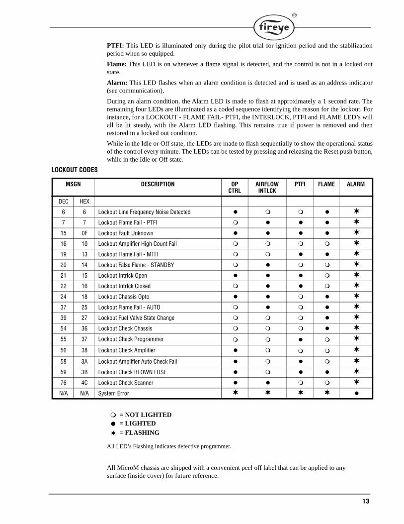
During an alarm condition, the Alarm LED is made to flash at approximately a 1 second rate. Theremaining four LEDs are illuminated as a coded sequence identifying the reason for the lockout. Forinstance, for a LOCKOUT - FLAME FAIL- PTFI, the INTERLOCK, PTFI and FLAME LED’s willall be lit steady, with the Alarm LED flashing. This remains true if power is removed and thenrestored in a locked out condition.
While in the Idle or Off state, the LEDs are made to flash sequentially to show the operational statusof the control every minute. The LEDs can be tested by pressing and releasing the Reset push button,while in the Idle or Off state.
LOCKOUT CODES
All LED’s Flashing indicates defective programmer.
All MicroM chassis are shipped with a convenient peel off label that can be applied to any surface (inside cover) for future reference.
MSGN DESCRIPTION OP CTRL
AIRFLOWINTLCK
PTFI FLAME ALARM
DEC HEX
6 6 Lockout Line Frequency Noise Detected 7 7 Lockout Flame Fail - PTFI 15 0F Lockout Fault Unknown 16 10 Lockout Amplifier High Count Fail 19 13 Lockout Flame Fail - MTFI 20 14 Lockout False Flame - STANDBY 21 15 Lockout Intrlck Open 22 16 Lockout Intrlck Closed 24 18 Lockout Chassis Opto 37 25 Lockout Flame Fail - AUTO 39 27 Lockout Fuel Valve State Change 54 36 Lockout Check Chassis 55 37 Lockout Check Programmer 56 38 Lockout Check Amplifier 58 3A Lockout Amplifier Auto Check Fail 59 3B Lockout Check BLOWN FUSE 76 4C Lockout Check Scanner N/A N/A System Error
= NOT LIGHTED
= LIGHTED
= FLASHING
14
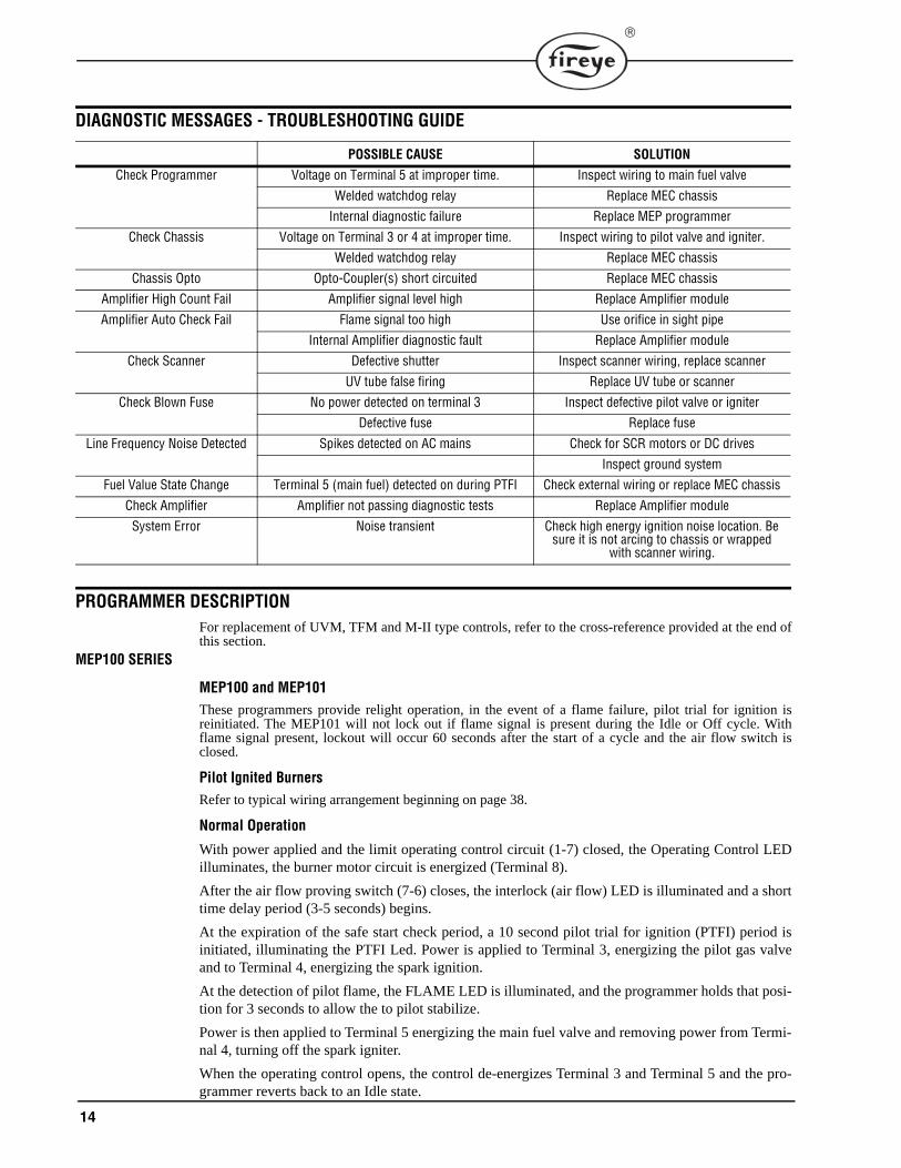
DIAGNOSTIC MESSAGES - TROUBLESHOOTING GUIDE
PROGRAMMER DESCRIPTIONFor replacement of UVM, TFM and M-II type controls, refer to the cross-reference provided at the end ofthis section.
MEP100 SERIES
MEP100 and MEP101These programmers provide relight operation, in the event of a flame failure, pilot trial for ignition isreinitiated. The MEP101 will not lock out if flame signal is present during the Idle or Off cycle. Withflame signal present, lockout will occur 60 seconds after the start of a cycle and the air flow switch isclosed.
Pilot Ignited BurnersRefer to typical wiring arrangement beginning on page 38.
Normal Operation
With power applied and the limit operating control circuit (1-7) closed, the Operating Control LEDilluminates, the burner motor circuit is energized (Terminal 8).
After the air flow proving switch (7-6) closes, the interlock (air flow) LED is illuminated and a shorttime delay period (3-5 seconds) begins.
At the expiration of the safe start check period, a 10 second pilot trial for ignition (PTFI) period isinitiated, illuminating the PTFI Led. Power is applied to Terminal 3, energizing the pilot gas valveand to Terminal 4, energizing the spark ignition.
At the detection of pilot flame, the FLAME LED is illuminated, and the programmer holds that posi-tion for 3 seconds to allow the to pilot stabilize.
Power is then applied to Terminal 5 energizing the main fuel valve and removing power from Termi-nal 4, turning off the spark igniter.
When the operating control opens, the control de-energizes Terminal 3 and Terminal 5 and the pro-grammer reverts back to an Idle state.
POSSIBLE CAUSE SOLUTION
Check Programmer Voltage on Terminal 5 at improper time. Inspect wiring to main fuel valve
Welded watchdog relay Replace MEC chassis
Internal diagnostic failure Replace MEP programmer
Check Chassis Voltage on Terminal 3 or 4 at improper time. Inspect wiring to pilot valve and igniter.
Welded watchdog relay Replace MEC chassis
Chassis Opto Opto-Coupler(s) short circuited Replace MEC chassis
Amplifier High Count Fail Amplifier signal level high Replace Amplifier module
Amplifier Auto Check Fail Flame signal too high Use orifice in sight pipe
Internal Amplifier diagnostic fault Replace Amplifier module
Check Scanner Defective shutter Inspect scanner wiring, replace scanner
UV tube false firing Replace UV tube or scanner
Check Blown Fuse No power detected on terminal 3 Inspect defective pilot valve or igniter
Defective fuse Replace fuse
Line Frequency Noise Detected Spikes detected on AC mains Check for SCR motors or DC drives
Inspect ground system
Fuel Value State Change Terminal 5 (main fuel) detected on during PTFI Check external wiring or replace MEC chassis
Check Amplifier Amplifier not passing diagnostic tests Replace Amplifier module
System Error Noise transient Check high energy ignition noise location. Be sure it is not arcing to chassis or wrapped
with scanner wiring.
15
Safety Shutdown
In the event pilot flame is not detected at the end of the 10 second PTFI period, the pilot gas valveand spark ignition are de-energized. A safety lockout occurs which de-energizes the burner motorand energizes the lockout alarm relay circuit, lighting the Alarm LED, 15 seconds after the safetylockout occurs. Manual reset is required.
In the event of a flame failure during a firing period, the main fuel valve is de-energized (Terminal 5)and the spark ignition is re-energized (Terminal 4), the PTFI period begins again as described aboveunder Normal Operation.
In the event of the interlock switch opening, the main fuel valve and pilot valve are de-energized.The control reverts back to the Idle state and begins again a new cycle starting with the safe startcheck period.
Direct Spark Ignited Burners
Refer to typical wiring arrangement illustrated on pages 40 and 41.
Normal Operation
With power applied and the limit operating control circuit (1-7) closed, the Operating Control LEDilluminates, the burner motor circuit is energized (Terminal 8).
The interlock proving switch (7-6) closes, the INTRLCK LED is illuminated and a short time delayperiod (3 seconds) begins (safe start check period).
At the expiration of the safe start check period, a 10 second PTFI period is initiated. The PTFI Led isilluminated, power is applied to Terminal 3, energizing the main fuel valve and to Terminal 4, ener-gizing the spark ignition.
At the detection of main flame, the FLAME LED is illuminated, and the programmer holds that posi-tion for 3-5 seconds to allow the main flame to stabilize.
Power is then removed from Terminal 4, turning off the spark igniter.
When the operating control opens, the control de-energizes Terminal 3 and Terminal 5 and the pro-grammer reverts back to an Idle state. Terminal 8 is immediately de-energized.
Safety Shutdown
In the event the main flame is not detected at the end of a 10 second PTFI period, the main fuel valveand spark ignition are de-energized. A safety lockout occurs which de-energizes the burner motorand energizes the lockout alarm relay circuit, lighting the Alarm LED, 15 seconds after the safetylockout occurs. Manual reset is required.
In the event of a flame failure during a firing period, the secondary fuel valve (if used) is de-ener-gized and the spark ignition is re-energized, the PTFI period begins again as described above underNormal Operation.
In the event of the interlock switch opening, the main fuel valve and pilot valve are de-energized.The control reverts back to the Idle state and begins again a new cycle starting with the safe startcheck period.
MEP102 & MEP104
The MEP102 and MEP104 programmers operate the same as the MEP100, except the PTFI time islimited to 5 seconds and 10 seconds respectively, the relight feature is eliminated and instead, thecontrol will enter safety lockout on flame failure. Recycle to the start of safe start check period tobegin a new cycle will occur on air flow switch opening.
MEP103
The MEP103 programmer implements a fixed 10 second spark igniter sensing period (SISP) used todetect spark, followed by a 10 second main trial for ignition (MTFI). Safety lockout occurs on flamefailure during the main firing period (AUTO). Recycle occurs on air flow switch opening. If spark isnot detected during the spark igniter sensing period the control makes one attempt to establish pilot
16
following a post purge of 30 seconds and a safe start check. Failure to ignition spark on the secondattempt results in safety lockout.
MEP100P
The MEP100P programmers provides a fixed 15 second post purge period upon detection of theoperating Control (1-7) or Air Flow switch (7-6) opening.
MEP100 as FLAME SWITCH (refer to Figure 11)
For systems that require flame switch operation, that is, relay KF will toggle on with flame signaland off without flame signal, the MicroM provides this function when equipped with an MEP100programmer. To operate as a flame switch, Terminals 1 and 6 MUST be powered with 120 VACwhile Terminal 7 MUST be left unpowered. Terminals 3, 4, and 5 will provide an isolated (KL relaynot energized) set of contacts with Terminal 3 being the common input, Terminal 4 will be normallyclosed and Terminal 5 will be normally open. If Terminal 7 is powered or if Terminal 6 is non-powered and a flame signal is present, the MicroM will lockout after 1 minute and Terminals 4and 5 will no longer switch with flame signal. Refer to Figure 11 for configuration wiring. AirFlow LED will blink while flame is detected.
TIMING CHART
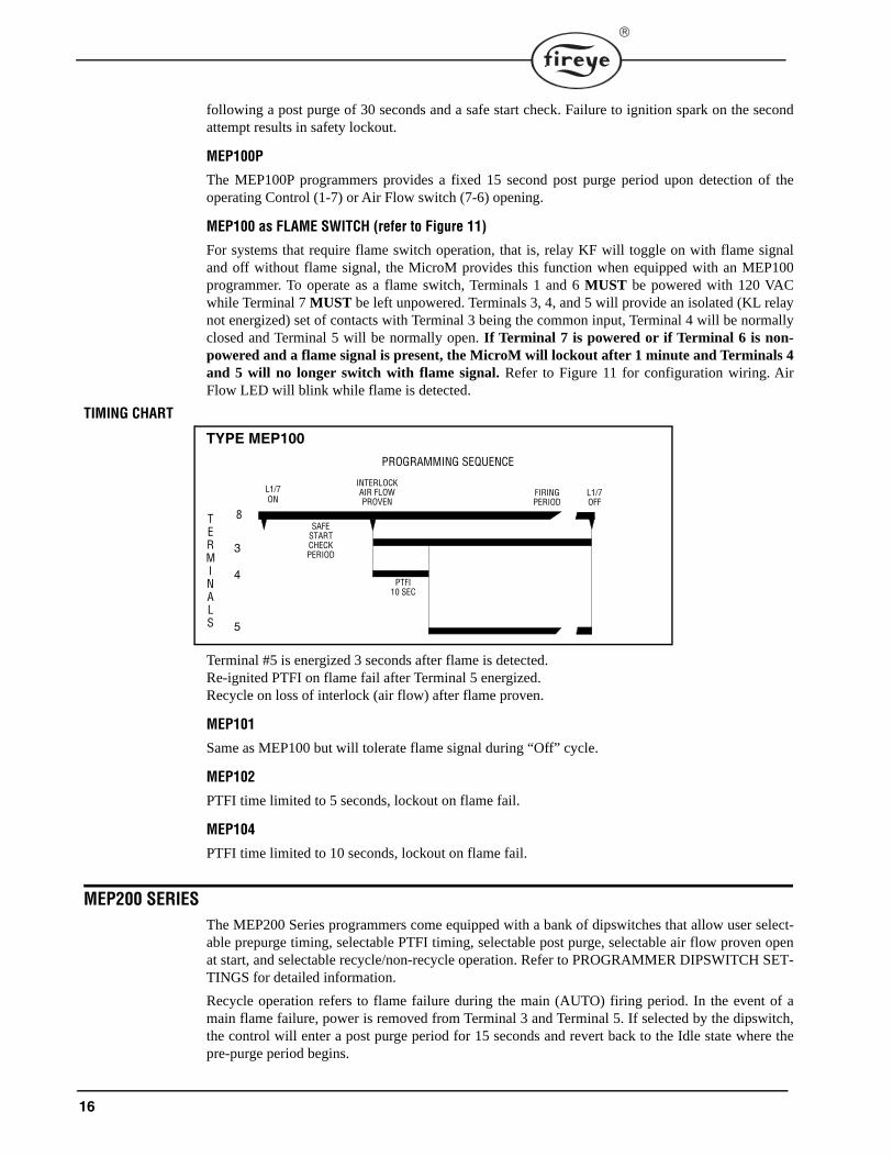
Terminal #5 is energized 3 seconds after flame is detected.Re-ignited PTFI on flame fail after Terminal 5 energized.Recycle on loss of interlock (air flow) after flame proven.
MEP101
Same as MEP100 but will tolerate flame signal during “Off” cycle.
MEP102
PTFI time limited to 5 seconds, lockout on flame fail.
MEP104
PTFI time limited to 10 seconds, lockout on flame fail.
MEP200 SERIESThe MEP200 Series programmers come equipped with a bank of dipswitches that allow user select-able prepurge timing, selectable PTFI timing, selectable post purge, selectable air flow proven openat start, and selectable recycle/non-recycle operation. Refer to PROGRAMMER DIPSWITCH SET-TINGS for detailed information.
Recycle operation refers to flame failure during the main (AUTO) firing period. In the event of amain flame failure, power is removed from Terminal 3 and Terminal 5. If selected by the dipswitch,the control will enter a post purge period for 15 seconds and revert back to the Idle state where thepre-purge period begins.
TYPE MEP100PROGRAMMING SEQUENCE
L1/7ON
INTERLOCKAIR FLOWPROVEN
FIRINGPERIOD
L1/7OFF
PTFI10 SEC
SAFESTARTCHECKPERIOD
8TERMINALS
3
4
5
17
If non-recycle operation is selected, in the event of a main flame failure, power is removed from Ter-minal 3 and Terminal 5. The control will enter a forced post purge period of 15 seconds, after whichthe Alarm LED is illuminated and the alarm relay is energized putting power on Terminal A.
The MEP230H programmer operates the same as the MEP230 with the exception of an additional 8second pilot stabilization. After flame is detected during the trial for ignition period, the powering ofTerminal 5 is delayed for eight (8) seconds. Terminal 4 remains powered during the stabilizationperiod. This function is offered primarily for two-stage light oil burners, to assure a specific delaybetween light off of the first and second stage, and to provide additional ignition timing to improveflame stabilization.
The MEP290 programmer operates the same as the MEP230 with the exception that post purge isselectable from 0 to 90 seconds.
MEP235
The MEP235 programmer operates the same as the MEP230 except flame failure during the firingperiod causes lockout. Dipswitch #6 refers to Recycle/Non-Recycle on a loss of air flow (Terminal 6)after flame is proven. The running interlock circuit (Terminal 6) must be proven closed within 10seconds after start of a cycle.
MEP236
The MEP236 programmer provides a 3 second main flame stabilization period by keeping Terminal#4 (igniter) energized while the main fuel valve (Terminal #5) opens. The MEP236 is to be used onan intermittent pilot only.
TIMING CHARTS
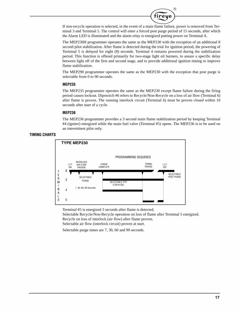
Terminal #5 is energized 3 seconds after flame is detected.Selectable Recycle/Non-Recycle operation on loss of flame after Terminal 5 energized.Recycle on loss of interlock (air flow) after flame proven.Selectable air flow (interlock circuit) proven at start.
Selectable purge times are 7, 30, 60 and 90 seconds.
TYPE MEP230
PROGRAMMING SEQUENCE
L1/7ON
PURGECOMPLETE
FIRINGPERIOD
L1/7OFF
SELECTABLE PTFI5 OR10 SEC
SELECTABLEPURGE
7, 30, 60, 90 Seconds
8TERMINALS
3
4
5
SELECTABLE POST PURGE
INTERLOCKAIR FLOWPROVEN
18
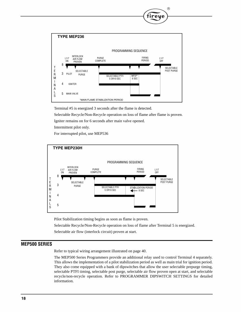
Terminal #5 is energized 3 seconds after the flame is detected.
Selectable Recycle/Non-Recycle operation on loss of flame after flame is proven.
Igniter remains on for 6 seconds after main valve opened.
Intermittent pilot only.
For interrupted pilot, use MEP536
Pilot Stabilization timing begins as soon as flame is proven.
Selectable Recycle/Non-Recycle operation on loss of flame after Terminal 5 is energized.
Selectable air flow (interlock circuit) proven at start.
MEP500 SERIESRefer to typical wiring arrangement illustrated on page 40.
The MEP500 Series Programmers provide an additional relay used to control Terminal 4 separately.This allows the implementation of a pilot stabilization period as well as main trial for ignition period.They also come equipped with a bank of dipswitches that allow the user selectable prepurge timing,selectable PTFI timing, selectable post purge, selectable air flow proven open at start, and selectablerecycle/non-recycle operation. Refer to PROGRAMMER DIPSWITCH SETTINGS for detailedinformation.
TYPE MEP236
PROGRAMMING SEQUENCE
L1/7ON
PURGECOMPLETE
FIRINGPERIOD
L1/7OFF
SELECTABLE PTFI5 OR10 SEC
SELECTABLEPURGE
8TERMINALS
3
4
5
SELECTABLE POST PURGE
PILOT
IGNITER
MAIN VALVE
MFSP*6 SEC
*MAIN FLAME STABILIZATION PERIOD
INTERLOCKAIR FLOWPROVEN
TYPE MEP230H
PROGRAMMING SEQUENCE
L1/7ON
PURGECOMPLETE
FIRINGPERIOD
L1/7OFF
SELECTABLE PTFI5 OR10 SEC
SELECTABLEPURGE
8TERMINALS
3
4
5
SELECTABLE POST PURGE
STABILIZATION PERIOD8 SEC
INTERLOCKAIR FLOWPROVEN
19
A “run-check” switch is also provided to assist in testing size, position and stabilization of pilot inconjunction with the flame detector,
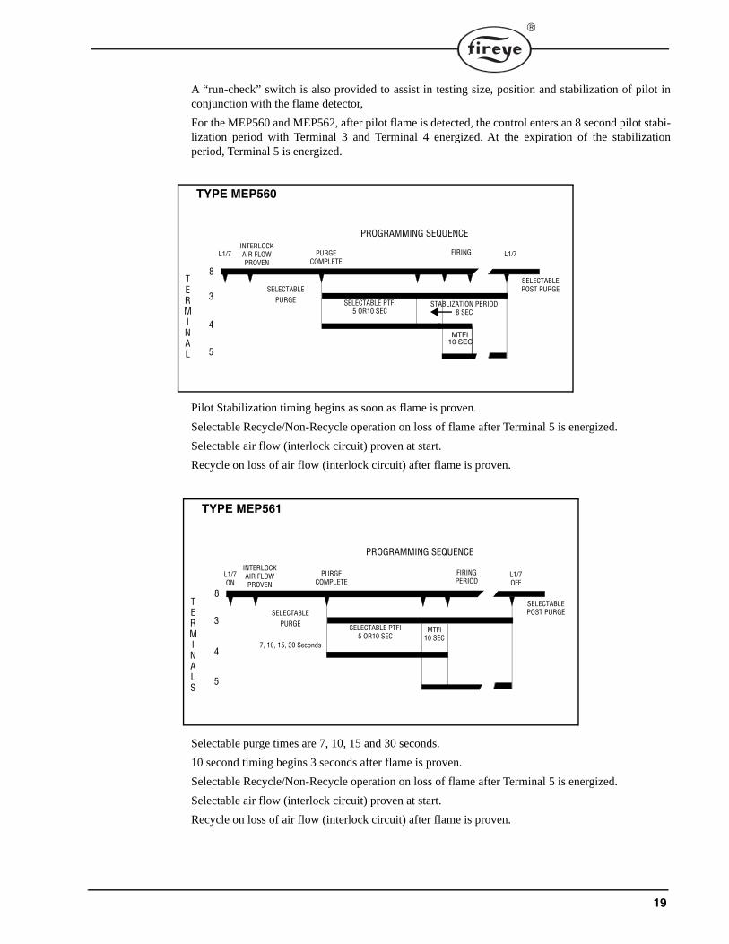
For the MEP560 and MEP562, after pilot flame is detected, the control enters an 8 second pilot stabi-lization period with Terminal 3 and Terminal 4 energized. At the expiration of the stabilizationperiod, Terminal 5 is energized.
Pilot Stabilization timing begins as soon as flame is proven.
Selectable Recycle/Non-Recycle operation on loss of flame after Terminal 5 is energized.
Selectable air flow (interlock circuit) proven at start.
Recycle on loss of air flow (interlock circuit) after flame is proven.
Selectable purge times are 7, 10, 15 and 30 seconds.
10 second timing begins 3 seconds after flame is proven.
Selectable Recycle/Non-Recycle operation on loss of flame after Terminal 5 is energized.
Selectable air flow (interlock circuit) proven at start.
Recycle on loss of air flow (interlock circuit) after flame is proven.
TYPE MEP560
PROGRAMMING SEQUENCE
L1/7 PURGECOMPLETE
FIRING L1/7
SELECTABLE PTFI5 OR10 SEC
SELECTABLEPURGE
8TERMINAL
3
4
5
SELECTABLE POST PURGE
STABLIZATION PERIOD8 SEC
MTFI10 SEC
INTERLOCKAIR FLOWPROVEN
TYPE MEP561
PROGRAMMING SEQUENCE
L1/7ON
PURGECOMPLETE
FIRINGPERIOD
L1/7OFF
SELECTABLE PTFI5 OR10 SEC
SELECTABLEPURGE
7, 10, 15, 30 Seconds
8TERMINALS
3
4
5
SELECTABLE POST PURGE
MTFI10 SEC
INTERLOCKAIR FLOWPROVEN
20
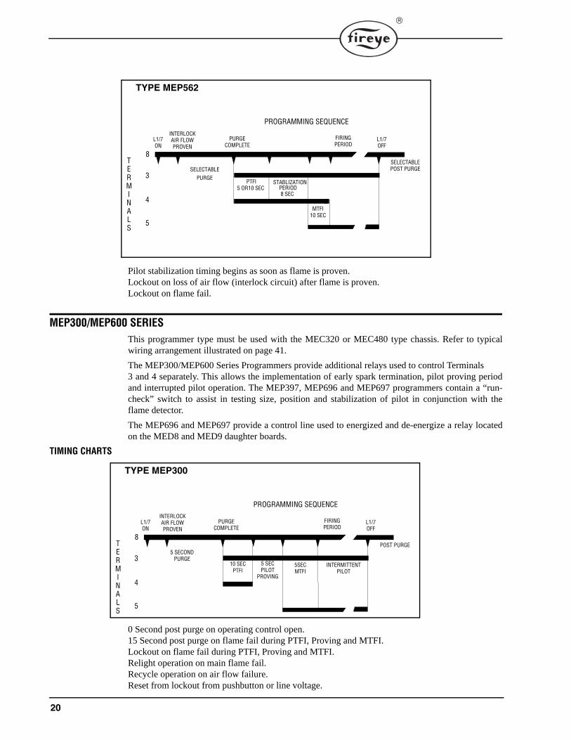
Pilot stabilization timing begins as soon as flame is proven.Lockout on loss of air flow (interlock circuit) after flame is proven.Lockout on flame fail.
MEP300/MEP600 SERIESThis programmer type must be used with the MEC320 or MEC480 type chassis. Refer to typicalwiring arrangement illustrated on page 41.
The MEP300/MEP600 Series Programmers provide additional relays used to control Terminals3 and 4 separately. This allows the implementation of early spark termination, pilot proving periodand interrupted pilot operation. The MEP397, MEP696 and MEP697 programmers contain a “run-check” switch to assist in testing size, position and stabilization of pilot in conjunction with theflame detector.
The MEP696 and MEP697 provide a control line used to energized and de-energize a relay locatedon the MED8 and MED9 daughter boards.
TIMING CHARTS
0 Second post purge on operating control open.15 Second post purge on flame fail during PTFI, Proving and MTFI.Lockout on flame fail during PTFI, Proving and MTFI.Relight operation on main flame fail.Recycle operation on air flow failure.Reset from lockout from pushbutton or line voltage.
TYPE MEP562
PROGRAMMING SEQUENCE
L1/7ON
PURGECOMPLETE
FIRINGPERIOD
L1/7OFF
PTFI5 OR10 SEC
SELECTABLEPURGE
8TERMINALS
3
4
5
SELECTABLE POST PURGE
MTFI10 SEC
STABLIZATION
8 SEC PERIOD
INTERLOCKAIR FLOWPROVEN
TYPE MEP300
PROGRAMMING SEQUENCE
L1/7ON
PURGECOMPLETE
FIRINGPERIOD
L1/7OFF
10 SECPTFI
5 SECONDPURGE
8TERMINALS
3
4
5
POST PURGE
INTERLOCKAIR FLOWPROVEN
5 SECPILOT
PROVING
5SECMTFI
INTERMITTENTPILOT
21
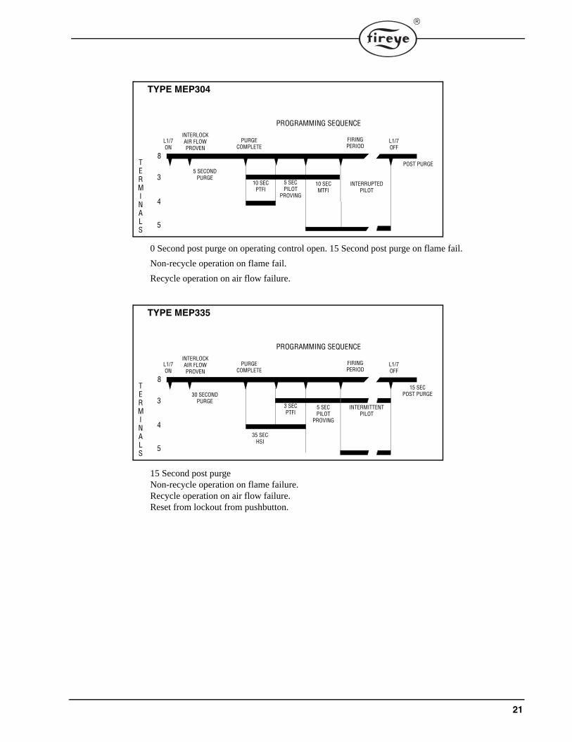
0 Second post purge on operating control open. 15 Second post purge on flame fail.
Non-recycle operation on flame fail.
Recycle operation on air flow failure.
15 Second post purgeNon-recycle operation on flame failure.Recycle operation on air flow failure.Reset from lockout from pushbutton.
TYPE MEP304
PROGRAMMING SEQUENCE
L1/7ON
PURGECOMPLETE
FIRINGPERIOD
L1/7OFF
10 SECPTFI
5 SECONDPURGE
8TERMINALS
3
4
5
POST PURGE
INTERLOCKAIR FLOWPROVEN
5 SECPILOT
PROVING
10 SECMTFI
INTERRUPTEDPILOT
TYPE MEP335
PROGRAMMING SEQUENCE
L1/7ON
PURGECOMPLETE
FIRINGPERIOD
L1/7OFF
35 SECHSI
30 SECONDPURGE
8TERMINALS
3
4
5
15 SECPOST PURGE
INTERLOCKAIR FLOWPROVEN
3 SECPTFI
5 SECPILOT
PROVING
INTERMITTENTPILOT
22
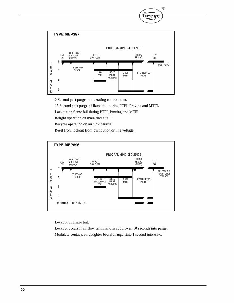
0 Second post purge on operating control open.
15 Second post purge of flame fail during PTFI, Proving and MTFI.
Lockout on flame fail during PTFI, Proving and MTFI.
Relight operation on main flame fail.
Recycle operation on air flow failure.
Reset from lockout from pushbutton or line voltage.
Lockout on flame fail.
Lockout occurs if air flow terminal 6 is not proven 10 seconds into purge.
Modulate contacts on daughter board change state 1 second into Auto.
TYPE MEP397
PROGRAMMING SEQUENCE
L1/7ON
PURGECOMPLETE
FIRINGPERIOD
L1/7OFF
7 SECPTFI
1 5 SECONDPURGE
8TERMINALS
3
4
5
POST PURGE
INTERLOCKAIR FLOWPROVEN
5 SECPILOT
PROVING
5 SECMTFI
INTERRUPTEDPILOT
TYPE MEP696
PROGRAMMING SEQUENCE
L1/7ON
PURGECOMPLETE
FIRINGPERIOD(AUTO)
L1/7OFF
5/10 SECSELECTABLE
PTFI
30 SECONDPURGE
8TERMINALS
3
4
5
SELECTABLE POST PURGE
0/60 SEC
INTERLOCKAIR FLOWPROVEN
5 SECPILOT
PROVING
5 SECMTFI
INTERRUPTEDPILOT
MODULATE CONTACTS
23
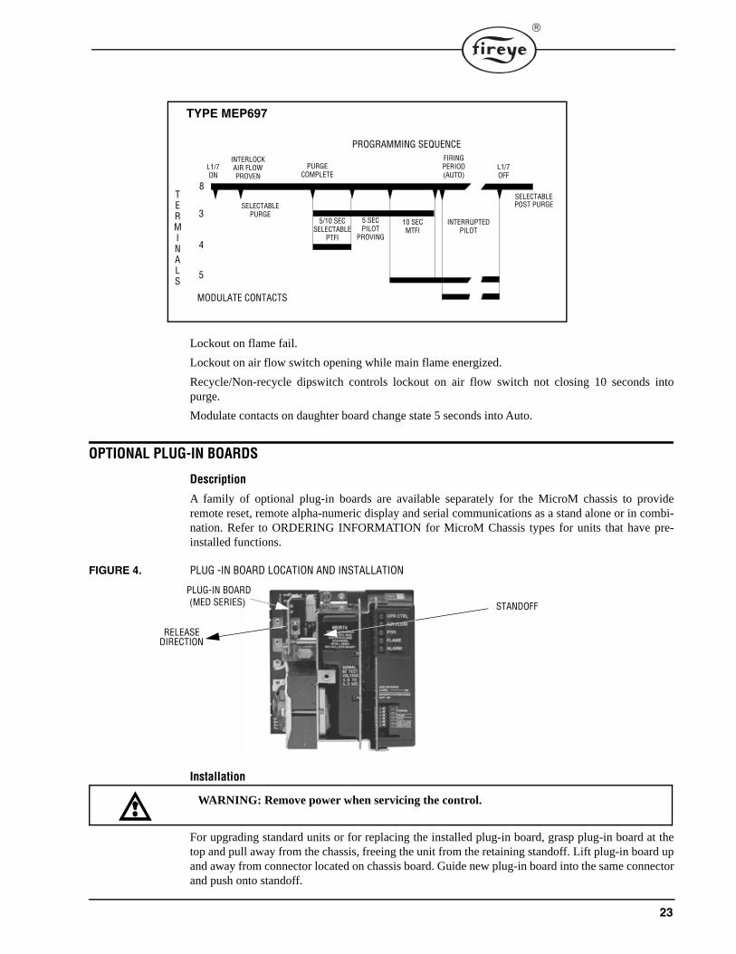
Lockout on flame fail.
Lockout on air flow switch opening while main flame energized.
Recycle/Non-recycle dipswitch controls lockout on air flow switch not closing 10 seconds intopurge.
Modulate contacts on daughter board change state 5 seconds into Auto.
OPTIONAL PLUG-IN BOARDS
Description
A family of optional plug-in boards are available separately for the MicroM chassis to provideremote reset, remote alpha-numeric display and serial communications as a stand alone or in combi-nation. Refer to ORDERING INFORMATION for MicroM Chassis types for units that have pre-installed functions.
FIGURE 4. PLUG -IN BOARD LOCATION AND INSTALLATION
Installation
For upgrading standard units or for replacing the installed plug-in board, grasp plug-in board at thetop and pull away from the chassis, freeing the unit from the retaining standoff. Lift plug-in board upand away from connector located on chassis board. Guide new plug-in board into the same connectorand push onto standoff.
TYPE MEP697
PROGRAMMING SEQUENCE
L1/7ON
PURGECOMPLETE
FIRINGPERIOD(AUTO)
L1/7OFF
5/10 SECSELECTABLE
PTFI
SELECTABLEPURGE
8TERMINALS
3
4
5
SELECTABLE POST PURGE
INTERLOCKAIR FLOWPROVEN
5 SECPILOT
PROVING
10 SECMTFI
INTERRUPTEDPILOT
MODULATE CONTACTS
STANDOFF
PLUG-IN BOARD(MED SERIES)
RELEASE DIRECTION
WARNING: Remove power when servicing the control.
24
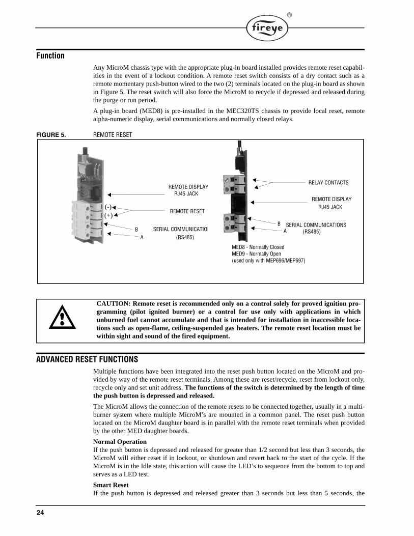
FunctionAny MicroM chassis type with the appropriate plug-in board installed provides remote reset capabil-ities in the event of a lockout condition. A remote reset switch consists of a dry contact such as aremote momentary push-button wired to the two (2) terminals located on the plug-in board as shownin Figure 5. The reset switch will also force the MicroM to recycle if depressed and released duringthe purge or run period.
A plug-in board (MED8) is pre-installed in the MEC320TS chassis to provide local reset, remotealpha-numeric display, serial communications and normally closed relays.
FIGURE 5. REMOTE RESET
ADVANCED RESET FUNCTIONSMultiple functions have been integrated into the reset push button located on the MicroM and pro-vided by way of the remote reset terminals. Among these are reset/recycle, reset from lockout only,recycle only and set unit address. The functions of the switch is determined by the length of timethe push button is depressed and released.
The MicroM allows the connection of the remote resets to be connected together, usually in a multi-burner system where multiple MicroM’s are mounted in a common panel. The reset push buttonlocated on the MicroM daughter board is in parallel with the remote reset terminals when providedby the other MED daughter boards.
Normal OperationIf the push button is depressed and released for greater than 1/2 second but less than 3 seconds, theMicroM will either reset if in lockout, or shutdown and revert back to the start of the cycle. If theMicroM is in the Idle state, this action will cause the LED’s to sequence from the bottom to top andserves as a LED test.
Smart ResetIf the push button is depressed and released greater than 3 seconds but less than 5 seconds, the
SERIAL COMMUNICATIONSA
B
REMOTE DISPLAYRJ45 JACK
REMOTE RESET
(RS485)
(+)(-)
SERIAL COMMUNICATIONS
REMOTE DISPLAYRJ45 JACK
RELAY CONTACTS
(RS485)B
A
MED8 - Normally ClosedMED9 - Normally Open (used only with MEP696/MEP697)
CAUTION: Remote reset is recommended only on a control solely for proved ignition pro-gramming (pilot ignited burner) or a control for use only with applications in whichunburned fuel cannot accumulate and that is intended for installation in inaccessible loca-tions such as open-flame, ceiling-suspended gas heaters. The remote reset location must bewithin sight and sound of the fired equipment.
25
MicroM will reset from the lockout state only. This is especially useful where, through the use ofremote reset daughter boards, all reset inputs can be connected together to a common reset pushbut-ton or intelligent device (PLC). If the push button is depressed as described above it will only causethe unit that is in lockout to reset and not effect any other units.
Smart RecycleIf the push button is depressed and released greater than 5 seconds but less than 7 seconds, all con-nected MicroM units will recycle back to the beginning of purge. All units that are in lockout willremain in lockout.
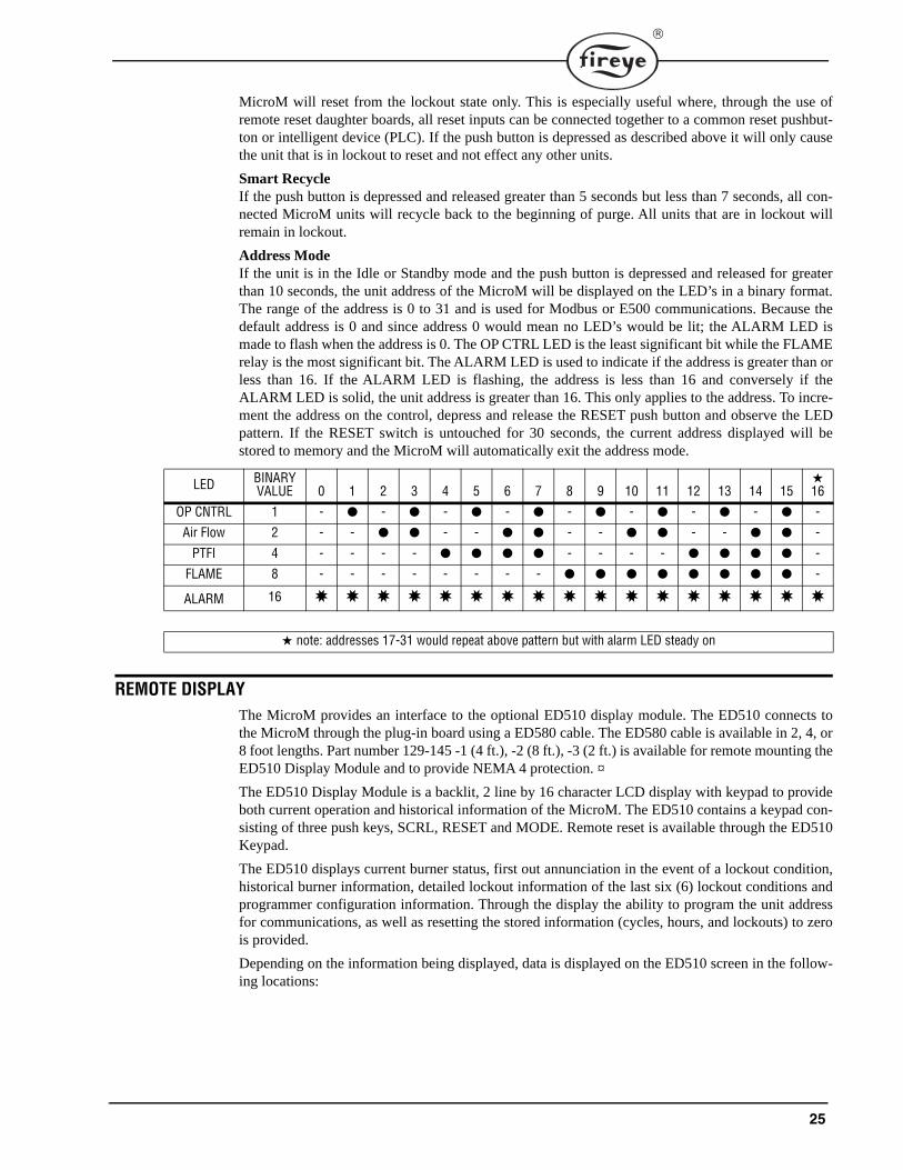
Address ModeIf the unit is in the Idle or Standby mode and the push button is depressed and released for greaterthan 10 seconds, the unit address of the MicroM will be displayed on the LED’s in a binary format.The range of the address is 0 to 31 and is used for Modbus or E500 communications. Because thedefault address is 0 and since address 0 would mean no LED’s would be lit; the ALARM LED ismade to flash when the address is 0. The OP CTRL LED is the least significant bit while the FLAMErelay is the most significant bit. The ALARM LED is used to indicate if the address is greater than orless than 16. If the ALARM LED is flashing, the address is less than 16 and conversely if theALARM LED is solid, the unit address is greater than 16. This only applies to the address. To incre-ment the address on the control, depress and release the RESET push button and observe the LEDpattern. If the RESET switch is untouched for 30 seconds, the current address displayed will bestored to memory and the MicroM will automatically exit the address mode.
REMOTE DISPLAYThe MicroM provides an interface to the optional ED510 display module. The ED510 connects tothe MicroM through the plug-in board using a ED580 cable. The ED580 cable is available in 2, 4, or8 foot lengths. Part number 129-145 -1 (4 ft.), -2 (8 ft.), -3 (2 ft.) is available for remote mounting theED510 Display Module and to provide NEMA 4 protection. ¤
The ED510 Display Module is a backlit, 2 line by 16 character LCD display with keypad to provideboth current operation and historical information of the MicroM. The ED510 contains a keypad con-sisting of three push keys, SCRL, RESET and MODE. Remote reset is available through the ED510Keypad.
The ED510 displays current burner status, first out annunciation in the event of a lockout condition,historical burner information, detailed lockout information of the last six (6) lockout conditions andprogrammer configuration information. Through the display the ability to program the unit addressfor communications, as well as resetting the stored information (cycles, hours, and lockouts) to zerois provided.
Depending on the information being displayed, data is displayed on the ED510 screen in the follow-ing locations:
LED BINARY VALUE 0 1 2 3 4 5 6 7 8 9 10 11 12 13 14 15
★16
OP CNTRL 1 - ● - ● - ● - ● - ● - ● - ● - ● -
Air Flow 2 - - ● ● - - ● ● - - ● ● - - ● ● -
PTFI 4 - - - - ● ● ● ● - - - - ● ● ● ● -
FLAME 8 - - - - - - - - ● ● ● ● ● ● ● ● -
ALARM 16 ✸ ✸ ✸ ✸ ✸ ✸ ✸ ✸ ✸ ✸ ✸ ✸ ✸ ✸ ✸ ✸ ✸
★ note: addresses 17-31 would repeat above pattern but with alarm LED steady on
26
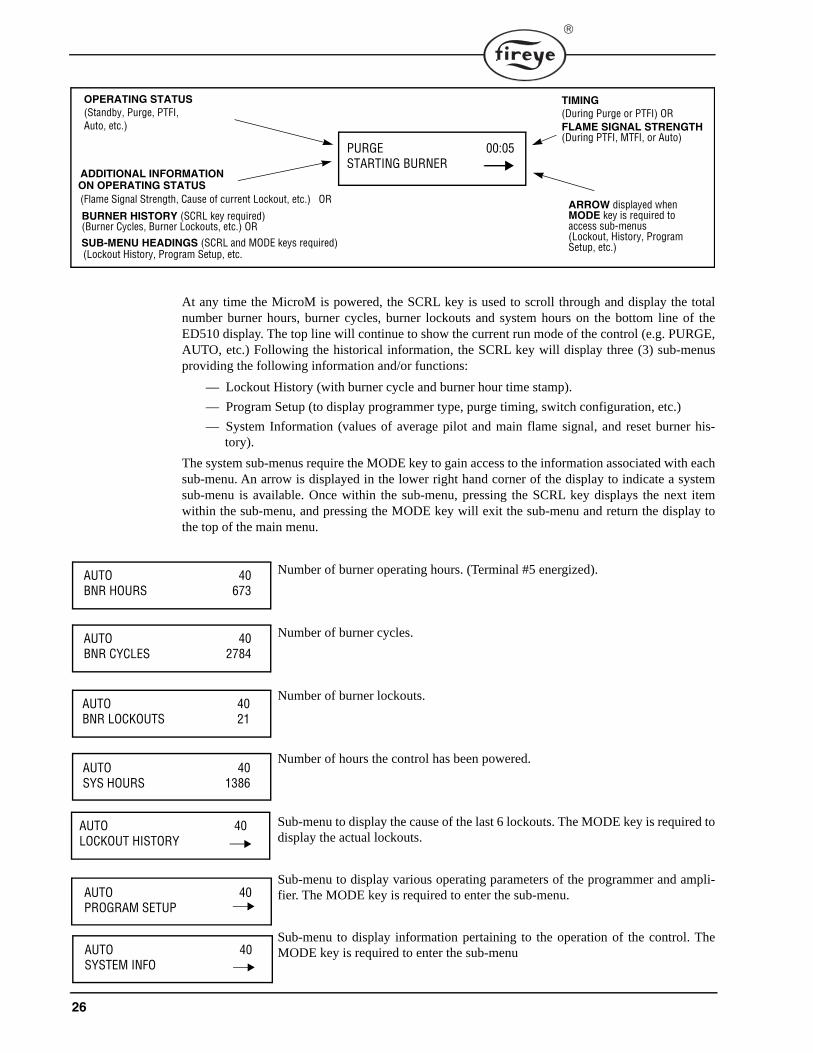
At any time the MicroM is powered, the SCRL key is used to scroll through and display the totalnumber burner hours, burner cycles, burner lockouts and system hours on the bottom line of theED510 display. The top line will continue to show the current run mode of the control (e.g. PURGE,AUTO, etc.) Following the historical information, the SCRL key will display three (3) sub-menusproviding the following information and/or functions:
— Lockout History (with burner cycle and burner hour time stamp).
— Program Setup (to display programmer type, purge timing, switch configuration, etc.)
— System Information (values of average pilot and main flame signal, and reset burner his-tory).
The system sub-menus require the MODE key to gain access to the information associated with eachsub-menu. An arrow is displayed in the lower right hand corner of the display to indicate a systemsub-menu is available. Once within the sub-menu, pressing the SCRL key displays the next itemwithin the sub-menu, and pressing the MODE key will exit the sub-menu and return the display tothe top of the main menu.
Number of burner operating hours. (Terminal #5 energized).
Number of burner cycles.
Number of burner lockouts.
Number of hours the control has been powered.
Sub-menu to display the cause of the last 6 lockouts. The MODE key is required todisplay the actual lockouts.
Sub-menu to display various operating parameters of the programmer and ampli-fier. The MODE key is required to enter the sub-menu.
Sub-menu to display information pertaining to the operation of the control. TheMODE key is required to enter the sub-menu
PURGE 00:05STARTING BURNER
OPERATING STATUS(Standby, Purge, PTFI, Auto, etc.)
ADDITIONAL INFORMATION
(Flame Signal Strength, Cause of current Lockout, etc.) OR
BURNER HISTORY (SCRL key required)(Burner Cycles, Burner Lockouts, etc.) ORSUB-MENU HEADINGS (SCRL and MODE keys required)(Lockout History, Program Setup, etc.
ON OPERATING STATUS
TIMING(During Purge or PTFI) ORFLAME SIGNAL STRENGTH(During PTFI, MTFI, or Auto)
ARROW displayed whenMODE key is required toaccess sub-menus(Lockout, History, Program Setup, etc.)
AUTO 40BNR HOURS 673
AUTO 40BNR CYCLES 2784
AUTO 40BNR LOCKOUTS 21
AUTO 40SYS HOURS 1386
AUTO 40LOCKOUT HISTORY
AUTO 40PROGRAM SETUP
AUTO 40SYSTEM INFO
27
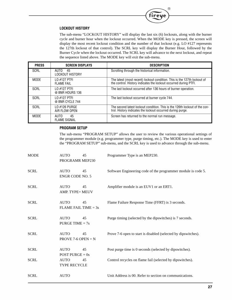
LOCKOUT HISTORY
The sub-menu “LOCKOUT HISTORY” will display the last six (6) lockouts, along with the burnercycle and burner hour when the lockout occurred. When the MODE key is pressed, the screen willdisplay the most recent lockout condition and the number of that lockout (e.g. LO #127 representsthe 127th lockout of that control). The SCRL key will display the Burner Hour, followed by theBurner Cycle when the lockout occurred. The SCRL key will advance to the next lockout, and repeatthe sequence listed above. The MODE key will exit the sub-menu.
PROGRAM SETUP
The sub-menu “PROGRAM SETUP” allows the user to review the various operational settings ofthe programmer module (e.g. programmer type, purge timing, etc.). The MODE key is used to enterthe “PROGRAM SETUP” sub-menu, and the SCRL key is used to advance through the sub-menu.
MODE AUTO 45 Programmer Type is an MEP230.
PROGRAMR MEP230
SCRL AUTO 45 Software Engineering code of the programmer module is code 5.
ENGR CODE NO. 5
SCRL AUTO 45 Amplifier module is an EUV1 or an ERT1.
AMP. TYPE= MEUV
SCRL AUTO 45 Flame Failure Response Time (FFRT) is 3 seconds.
FLAME FAIL TIME = 3s
SCRL AUTO 45 Purge timing (selected by the dipswitches) is 7 seconds.
PURGE TIME = 7s
SCRL AUTO 45 Prove 7-6 open to start is disabled (selected by dipswitches).
PROVE 7-6 OPEN = N
SCRL AUTO 45 Post purge time is 0 seconds (selected by dipswitches).
POST PURGE = 0s
SCRL AUTO 45 Control recycles on flame fail (selected by dipswitches).
TYPE RECYCLE
SCRL AUTO Unit Address is 00. Refer to section on communications.
PRESS SCREEN DISPLAYS DESCRIPTION
SCRL AUTO 45LOCKOUT HISTORY
Scrolling through the historical information.
MODE LO #127 PTFIFLAME FAIL
The latest (most recent) lockout condition. This is the 127th lockout of the control. History indicates the lockout occurred during PTFI.
SCRL LO #127 PTFI@ BNR HOURS 136
The last lockout occurred after 136 hours of burner operation.
SCRL LO #127 PTFI@ BNR CYCLE 744
The last lockout occurred at burner cycle 744.
SCRL LO #126 PURGEAIR FLOW OPEN
The second latest lockout condition. This is the 126th lockout of the con-trol. History indicates the lockout occurred during purge.
MODE AUTO 45FLAME SIGNAL
Screen has returned to the normal run message.
28
UNIT ADDRESS 00
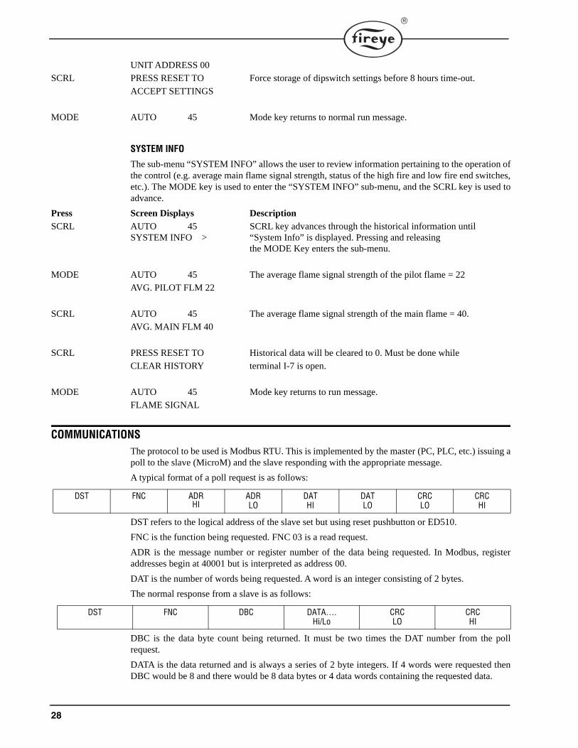
SCRL PRESS RESET TO Force storage of dipswitch settings before 8 hours time-out.
ACCEPT SETTINGS
MODE AUTO 45 Mode key returns to normal run message.
SYSTEM INFO
The sub-menu “SYSTEM INFO” allows the user to review information pertaining to the operation ofthe control (e.g. average main flame signal strength, status of the high fire and low fire end switches,etc.). The MODE key is used to enter the “SYSTEM INFO” sub-menu, and the SCRL key is used toadvance.
Press Screen Displays Description
SCRL AUTO 45 SCRL key advances through the historical information until SYSTEM INFO > “System Info” is displayed. Pressing and releasing
the MODE Key enters the sub-menu.
MODE AUTO 45 The average flame signal strength of the pilot flame = 22
AVG. PILOT FLM 22
SCRL AUTO 45 The average flame signal strength of the main flame = 40.
AVG. MAIN FLM 40
SCRL PRESS RESET TO Historical data will be cleared to 0. Must be done while
CLEAR HISTORY terminal I-7 is open.
MODE AUTO 45 Mode key returns to run message.
FLAME SIGNAL
COMMUNICATIONSThe protocol to be used is Modbus RTU. This is implemented by the master (PC, PLC, etc.) issuing apoll to the slave (MicroM) and the slave responding with the appropriate message.
A typical format of a poll request is as follows:
DST refers to the logical address of the slave set but using reset pushbutton or ED510.
FNC is the function being requested. FNC 03 is a read request.
ADR is the message number or register number of the data being requested. In Modbus, registeraddresses begin at 40001 but is interpreted as address 00.
DAT is the number of words being requested. A word is an integer consisting of 2 bytes.
The normal response from a slave is as follows:
DBC is the data byte count being returned. It must be two times the DAT number from the pollrequest.
DATA is the data returned and is always a series of 2 byte integers. If 4 words were requested thenDBC would be 8 and there would be 8 data bytes or 4 data words containing the requested data.
DST FNC ADRHI
ADRLO
DATHI
DATLO
CRCLO
CRCHI
DST FNC DBC DATA….Hi/Lo
CRCLO
CRCHI
29
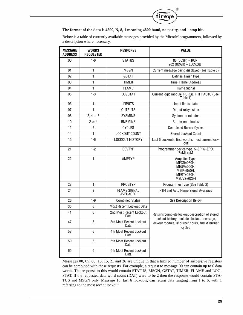
The format of the data is 4800, N, 8, 1 meaning 4800 baud, no parity, and 1 stop bit.
Below is a table of currently available messages provided by the MicroM programmers, followed bya description where necessary.
Messages 00, 05, 08, 10, 15, 21 and 26 are unique in that a limited number of successive registerscan be combined with these requests. For example, a request to message 00 can contain up to 6 datawords. The response to this would contain STATUS, MSGN, GSTAT, TIMER, FLAME and LOG-STAT. If the requested data word count (DAT) were to be 2 then the response would contain STA-TUS and MSGN only. Message 15, last 6 lockouts, can return data ranging from 1 to 6, with 1referring to the most recent lockout.
MESSAGEADDRESS
WORDSREQUESTED
RESPONSE VALUE
00 1-6 STATUS 83 (053H) = RUN;202 (0CAH) = LOCKOUT
01 1 MSGN Current message being displayed (see Table 3)
02 1 GSTAT Defines Timer Type
03 1 TIMER Time, Flame, Address
04 1 FLAME Flame Signal
05 1-3 LOGSTAT Current logic module, PURGE, PTFI, AUTO (See Table 1)
06 1 INPUTS Input limits state
07 1 OUTPUTS Output relays state
08 2, 4 or 8 SYSMINS System on minutes
10 2 or 4 BNRMINS Burner on minutes
12 2 CYCLES Completed Burner Cycles
14 1 LOCKOUT COUNT Stored Lockout Count
15 1-6 LOCKOUT HISTORY Last 6 Lockouts, first word is most current lock-out
21 1-2 DEVTYP Programmer device type, 5=EP, 6=EPD, 7=MicroM
22 1 AMPTYP Amplifier Type; MECD=080H;MEUV=090H;MEIR=0A0H;MERT=0B0H;MEUVS=0C0H
23 1 PROGTYP Programmer Type (See Table 2)
24 2 FLAME SIGNAL AVERAGES
PTFI and Auto Flame Signal Averages
26 1-9 Combined Status See Description Below
35 6 Most Recent Lockout Data
Returns complete lockout description of stored lockout history. Includes lockout message,
lockout module, @ burner hours, and @ burner cycles
41 6 2nd Most Recent Lockout Data
47 6 3rd Most Recent Lockout Data
53 6 4th Most Recent Lockout Data
59 6 5th Most Recent Lockout Data
65 6 6th Most Recent Lockout Data
30
Message 26 returns the current operating status as well as stored burner hours and burner cycles as asnapshot of the entire MicroM system. When all 9 words are requested, the data returned consists ofSTATUS, MSGN, FLAME, INPUTS, OUTPUTS, BNRMINS, and BNRCYCS.
The MSGN being transmitted is a numerical value and must be interpreted by the communicatingdevice, which actually is an advantage since this can be made to be whatever message text the enduser wants. In other words, it allows for programming custom messages without actually changingthe message in the programmer.
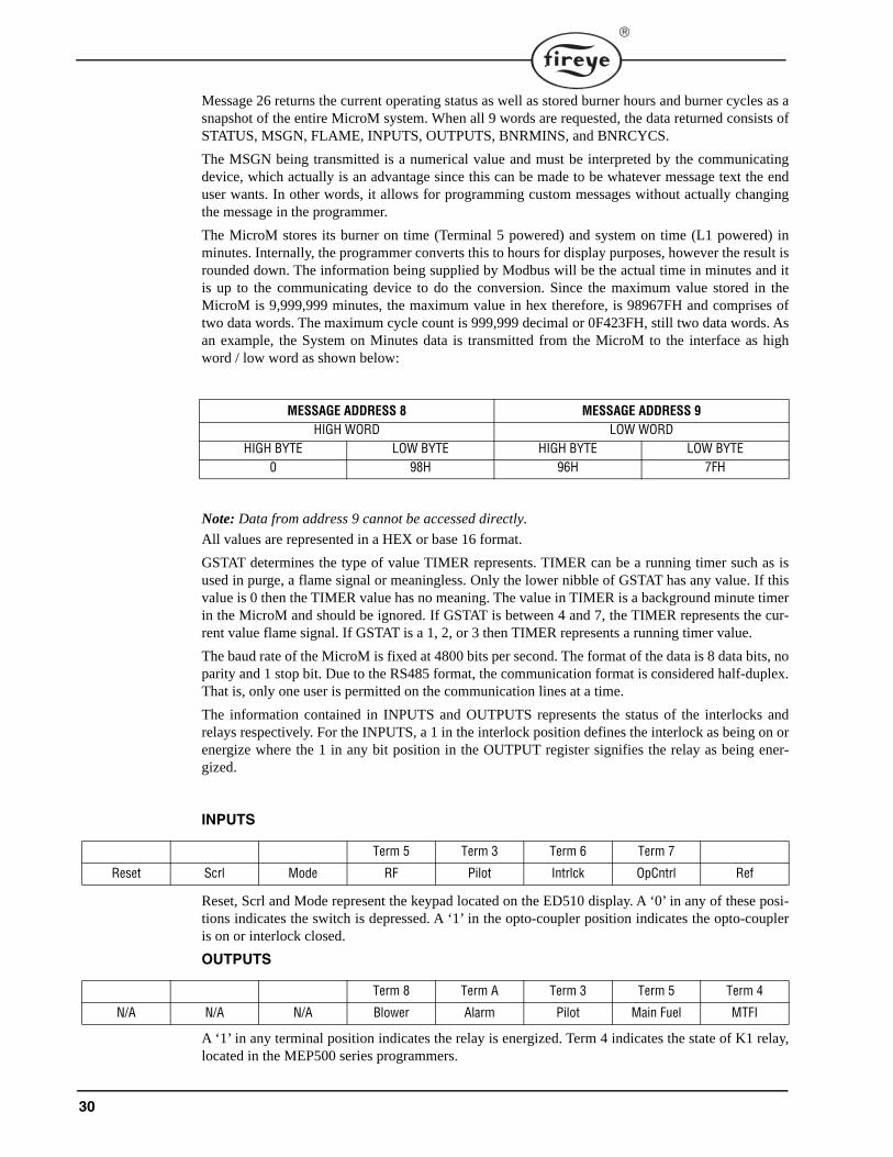
The MicroM stores its burner on time (Terminal 5 powered) and system on time (L1 powered) inminutes. Internally, the programmer converts this to hours for display purposes, however the result isrounded down. The information being supplied by Modbus will be the actual time in minutes and itis up to the communicating device to do the conversion. Since the maximum value stored in theMicroM is 9,999,999 minutes, the maximum value in hex therefore, is 98967FH and comprises oftwo data words. The maximum cycle count is 999,999 decimal or 0F423FH, still two data words. Asan example, the System on Minutes data is transmitted from the MicroM to the interface as highword / low word as shown below:
Note: Data from address 9 cannot be accessed directly.
All values are represented in a HEX or base 16 format.
GSTAT determines the type of value TIMER represents. TIMER can be a running timer such as isused in purge, a flame signal or meaningless. Only the lower nibble of GSTAT has any value. If thisvalue is 0 then the TIMER value has no meaning. The value in TIMER is a background minute timerin the MicroM and should be ignored. If GSTAT is between 4 and 7, the TIMER represents the cur-rent value flame signal. If GSTAT is a 1, 2, or 3 then TIMER represents a running timer value.
The baud rate of the MicroM is fixed at 4800 bits per second. The format of the data is 8 data bits, noparity and 1 stop bit. Due to the RS485 format, the communication format is considered half-duplex.That is, only one user is permitted on the communication lines at a time.
The information contained in INPUTS and OUTPUTS represents the status of the interlocks andrelays respectively. For the INPUTS, a 1 in the interlock position defines the interlock as being on orenergize where the 1 in any bit position in the OUTPUT register signifies the relay as being ener-gized.
Reset, Scrl and Mode represent the keypad located on the ED510 display. A ‘0’ in any of these posi-tions indicates the switch is depressed. A ‘1’ in the opto-coupler position indicates the opto-coupleris on or interlock closed.
A ‘1’ in any terminal position indicates the relay is energized. Term 4 indicates the state of K1 relay,located in the MEP500 series programmers.
MESSAGE ADDRESS 8 MESSAGE ADDRESS 9HIGH WORD LOW WORD
HIGH BYTE LOW BYTE HIGH BYTE LOW BYTE0 98H 96H 7FH
INPUTS
Term 5 Term 3 Term 6 Term 7
Reset Scrl Mode RF Pilot Intrlck OpCntrl Ref
OUTPUTS
Term 8 Term A Term 3 Term 5 Term 4
N/A N/A N/A Blower Alarm Pilot Main Fuel MTFI
31
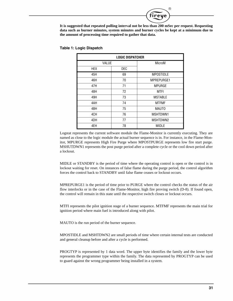
It is suggested that repeated polling interval not be less than 200 mSec per request. Requestingdata such as burner minutes, system minutes and burner cycles be kept at a minimum due tothe amount of processing time required to gather that data.
Logstat represents the current software module the Flame-Monitor is currently executing. They arenamed as close to the logic module the actual burner sequence is in. For instance, in the Flame-Mon-itor, MPURGE represents High Fire Purge where MPOSTPURGE represents low fire start purge.MSHUTDWN1 represents the post purge period after a complete cycle or the cool down period aftera lockout.
MIDLE or STANDBY is the period of time where the operating control is open or the control is inlockout waiting for reset. On instances of false flame during the purge period, the control algorithmforces the control back to STANDBY until false flame ceases or lockout occurs.
MPREPURGE1 is the period of time prior to PURGE where the control checks the status of the airflow interlocks or in the case of the Flame-Monitor, high fire proving switch (D-8). If found open,the control will remain in this state until the respective switch closes or lockout occurs.
MTFI represents the pilot ignition stage of a burner sequence. MTFMF represents the main trial forignition period where main fuel is introduced along with pilot.
MAUTO is the run period of the burner sequence.
MPOSTIDLE and MSHTDWN2 are small periods of time where certain internal tests are conductedand general cleanup before and after a cycle is performed.
PROGTYP is represented by 1 data word. The upper byte identifies the family and the lower byterepresents the programmer type within the family. The data represented by PROGTYP can be usedto guard against the wrong programmer being installed in a system.
Table 1: Logic Dispatch
LOGIC DISPATCHER
VALUE MicroM
HEX DEC
45H 69 MPOSTIDLE
46H 70 MPREPURGE1
47H 71 MPURGE
48H 72 MTFI
49H 73 MSTABLE
4AH 74 MTFMF
4BH 75 MAUTO
4CH 76 MSHTDWN1
4DH 77 MSHTDWN2
4EH 78 MIDLE
32
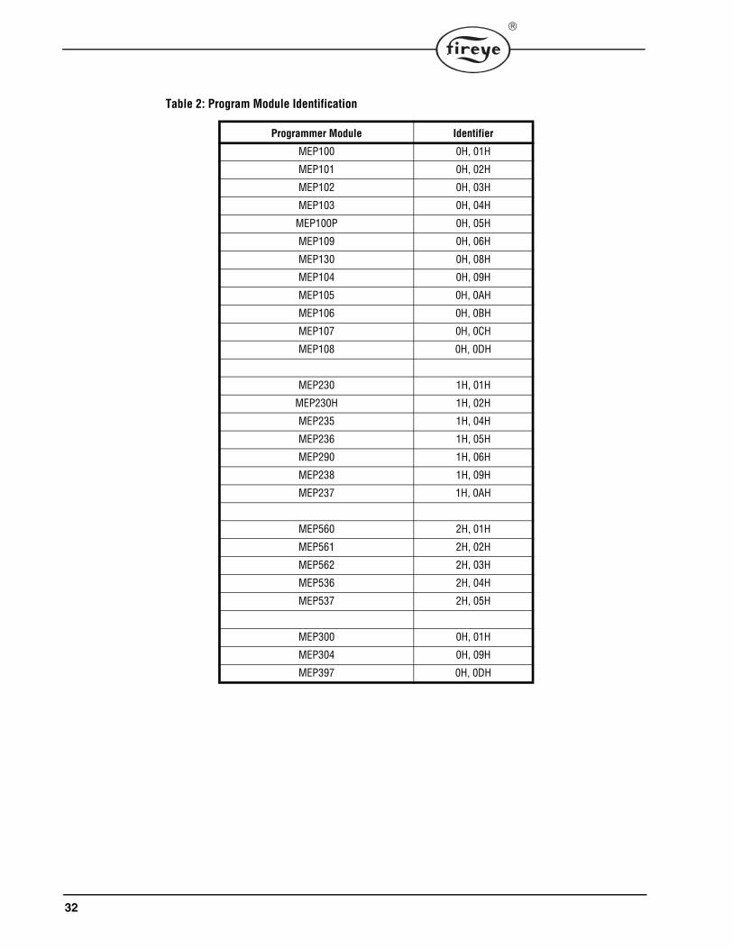
Table 2: Program Module Identification
Programmer Module Identifier
MEP100 0H, 01H
MEP101 0H, 02H
MEP102 0H, 03H
MEP103 0H, 04H
MEP100P 0H, 05H
MEP109 0H, 06H
MEP130 0H, 08H
MEP104 0H, 09H
MEP105 0H, 0AH
MEP106 0H, 0BH
MEP107 0H, 0CH
MEP108 0H, 0DH
MEP230 1H, 01H
MEP230H 1H, 02H
MEP235 1H, 04H
MEP236 1H, 05H
MEP290 1H, 06H
MEP238 1H, 09H
MEP237 1H, 0AH
MEP560 2H, 01H
MEP561 2H, 02H
MEP562 2H, 03H
MEP536 2H, 04H
MEP537 2H, 05H
MEP300 0H, 01H
MEP304 0H, 09H
MEP397 0H, 0DH
33
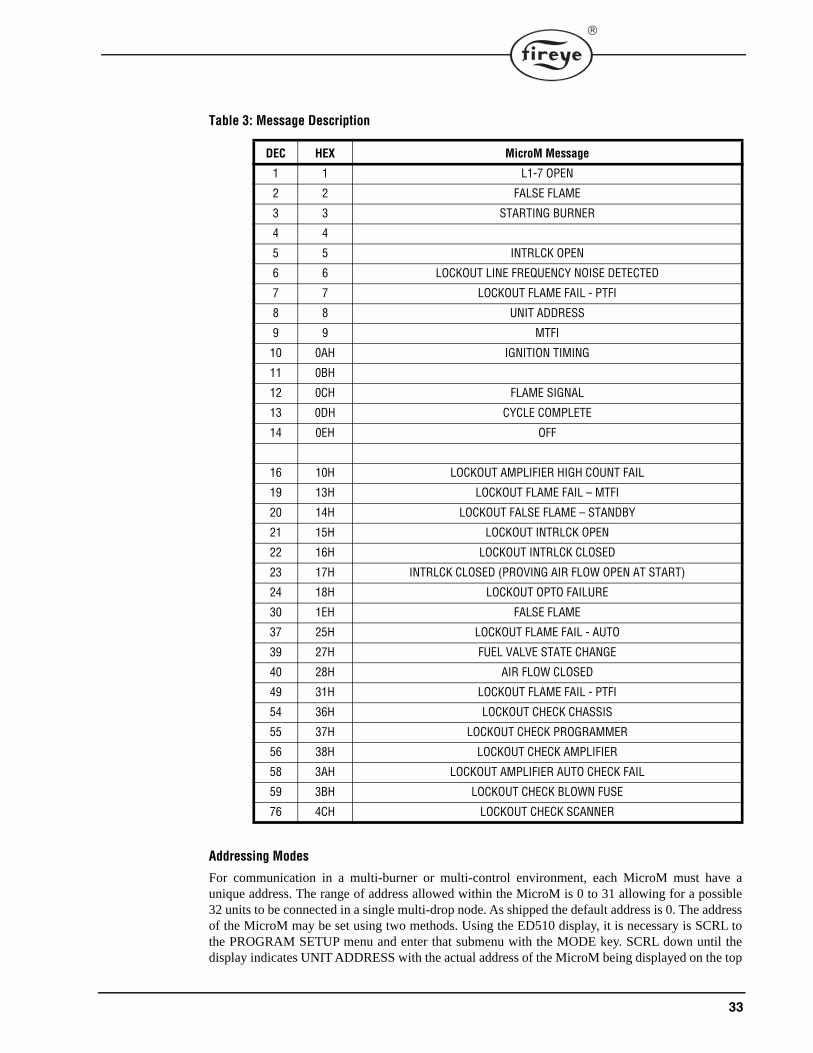
Addressing Modes
For communication in a multi-burner or multi-control environment, each MicroM must have aunique address. The range of address allowed within the MicroM is 0 to 31 allowing for a possible32 units to be connected in a single multi-drop node. As shipped the default address is 0. The addressof the MicroM may be set using two methods. Using the ED510 display, it is necessary is SCRL tothe PROGRAM SETUP menu and enter that submenu with the MODE key. SCRL down until thedisplay indicates UNIT ADDRESS with the actual address of the MicroM being displayed on the top
Table 3: Message Description
DEC HEX MicroM Message
1 1 L1-7 OPEN
2 2 FALSE FLAME
3 3 STARTING BURNER
4 4
5 5 INTRLCK OPEN
6 6 LOCKOUT LINE FREQUENCY NOISE DETECTED
7 7 LOCKOUT FLAME FAIL - PTFI
8 8 UNIT ADDRESS
9 9 MTFI
10 0AH IGNITION TIMING
11 0BH
12 0CH FLAME SIGNAL
13 0DH CYCLE COMPLETE
14 0EH OFF
16 10H LOCKOUT AMPLIFIER HIGH COUNT FAIL
19 13H LOCKOUT FLAME FAIL – MTFI
20 14H LOCKOUT FALSE FLAME – STANDBY
21 15H LOCKOUT INTRLCK OPEN
22 16H LOCKOUT INTRLCK CLOSED
23 17H INTRLCK CLOSED (PROVING AIR FLOW OPEN AT START)
24 18H LOCKOUT OPTO FAILURE
30 1EH FALSE FLAME
37 25H LOCKOUT FLAME FAIL - AUTO
39 27H FUEL VALVE STATE CHANGE
40 28H AIR FLOW CLOSED
49 31H LOCKOUT FLAME FAIL - PTFI
54 36H LOCKOUT CHECK CHASSIS
55 37H LOCKOUT CHECK PROGRAMMER
56 38H LOCKOUT CHECK AMPLIFIER
58 3AH LOCKOUT AMPLIFIER AUTO CHECK FAIL
59 3BH LOCKOUT CHECK BLOWN FUSE
76 4CH LOCKOUT CHECK SCANNER
34
line of the display. Pressing and releasing the RESET key will cause the address to increment. Theaddress after 31 is 0. The second method is to use the local reset located on the plug-in board. It isfirst necessary to open the operating control (L1-7) to have the MicroM in the IDLE or STANDBYposition. Depressing the reset switch for greater than 10 seconds will cause the address of theMicroM to be displayed in a binary format on the LEDs located on the programmer board. Becausethe default is address 0, and since address 0 would mean no LEDs would be lit; the ALARM LED ismade to flash when the address is 0. The OP CTRL LED is the least significant bit while theALARM relay is the most significant bit. To increment the address counter, depress and release theRESET push button and observe the LED pattern. If the RESET switch is untouched for 30 secondsthe current address displayed will be stored to memory and the MicroM will automatically exit theaddress mode.
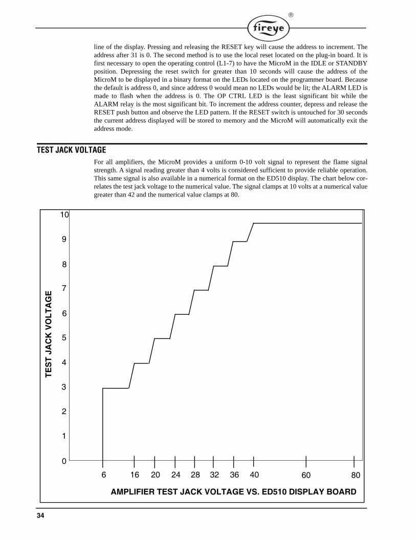
TEST JACK VOLTAGEFor all amplifiers, the MicroM provides a uniform 0-10 volt signal to represent the flame signalstrength. A signal reading greater than 4 volts is considered sufficient to provide reliable operation.This same signal is also available in a numerical format on the ED510 display. The chart below cor-relates the test jack voltage to the numerical value. The signal clamps at 10 volts at a numerical valuegreater than 42 and the numerical value clamps at 80.
0
1
2
3
4
5
6
7
8
9
10
6 16 20 24 28 32 36 40 60 80
AMPLIFIER TEST JACK VOLTAGE VS. ED510 DISPLAY BOARD
TES
T JA
CK
VO
LTA
GE
35
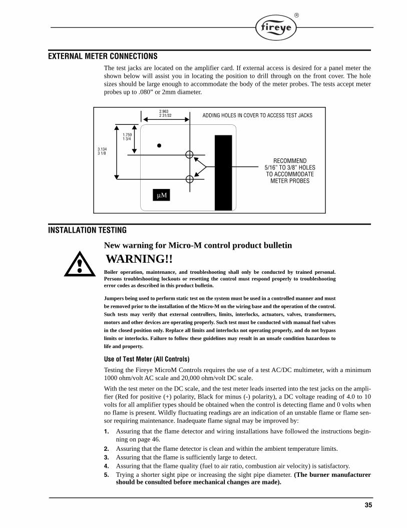
EXTERNAL METER CONNECTIONSThe test jacks are located on the amplifier card. If external access is desired for a panel meter theshown below will assist you in locating the position to drill through on the front cover. The holesizes should be large enough to accommodate the body of the meter probes. The tests accept meterprobes up to .080” or 2mm diameter.
INSTALLATION TESTING
New warning for Micro-M control product bulletin
WARNING!!Boiler operation, maintenance, and troubleshooting shall only be conducted by trained personal.Persons troubleshooting lockouts or resetting the control must respond properly to troubleshootingerror codes as described in this product bulletin.
Jumpers being used to perform static test on the system must be used in a controlled manner and must
be removed prior to the installation of the Micro-M on the wiring base and the operation of the control.
Such tests may verify that external controllers, limits, interlocks, actuators, valves, transformers,
motors and other devices are operating properly. Such test must be conducted with manual fuel valves
in the closed position only. Replace all limits and interlocks not operating properly, and do not bypass
limits or interlocks. Failure to follow these guidelines may result in an unsafe condition hazardous to
life and property.
Use of Test Meter (All Controls)
Testing the Fireye MicroM Controls requires the use of a test AC/DC multimeter, with a minimum1000 ohm/volt AC scale and 20,000 ohm/volt DC scale.
With the test meter on the DC scale, and the test meter leads inserted into the test jacks on the ampli-fier (Red for positive (+) polarity, Black for minus (-) polarity), a DC voltage reading of 4.0 to 10volts for all amplifier types should be obtained when the control is detecting flame and 0 volts whenno flame is present. Wildly fluctuating readings are an indication of an unstable flame or flame sen-sor requiring maintenance. Inadequate flame signal may be improved by:
1. Assuring that the flame detector and wiring installations have followed the instructions begin-ning on page 46.
2. Assuring that the flame detector is clean and within the ambient temperature limits. 3. Assuring that the flame is sufficiently large to detect.4. Assuring that the flame quality (fuel to air ratio, combustion air velocity) is satisfactory. 5. Trying a shorter sight pipe or increasing the sight pipe diameter. (The burner manufacturer
should be consulted before mechanical changes are made).
μΜ
RECOMMEND5/16” TO 3/8” HOLESTO ACCOMMODATE
METER PROBES
2.9632 31/32
1.7591 3/4
3.1343 1/8
ADDING HOLES IN COVER TO ACCESS TEST JACKS
36
When using a flame rectification amplifier, a micro-ammeter may be connected in series with thewire to Terminal S2. Normal flame will produce a meter reading between 4 and 10 micro-amps.
With the test meter on the AC scale, line and load voltages may be measured at the identified testpoints on the chassis.
Normal Pilot Flame Test (Programmers with Run/Check Switch)1. At pilot trial for ignition (PTFI) place the Run/Check switch in the Check position.
2. During the pilot flame test and adjustment period, if flame is not detected within 30 seconds, thecontrol will lock out and require manual reset to initiate another cycle.
3. Observe the pilot flame signal on the test meter or the ED510 display. If the flame signal isbelow 4.0 volts DC or a reading of 10 on a remote display, re-adjust the pilot flame or realignthe flame detector.
4. When using UV detection, a test is required to verify that UV radiation from the ignition sparkis not being detected. To accomplish this, manually shut off both the pilot and main fuels. Initi-ate a normal start-up. Observe the test meter which should read no more than 1/2 volt DC. Ifhigher levels are observed, realign the UV scanner, and/or shield the spark from the scanner’sview.
5. Move the Run/Check switch to the Run position, check pilot flame response time by manuallyshutting off the pilot fuel and initiate a normal start-up. With no pilot flame present, the controlwill de-energize the pilot assembly at the end of the trial for ignition interval (selectable by dip-switch #4) and go into safety shutdown.
Minimum Pilot Test
This test assures that the flame detector will not sense a pilot flame too small to light a the mainflame reliably. It must be made on every new installation as well as following the repositioning orreplacement of the flame detector. This procedure should not be used on a direct spark burner.
1. Manually shut off the fuel to the main burner.
2. Place the Run/Check switch in the Check position. (MEP500 Series Programmers only). 3. Connect a test meter to the test jacks on the Amplifier Module or observe the reading on the
ED510 display. 4. Initiate a normal start-up. 5. Reduce the fuel to the pilot until the DC voltmeter reads 4.0 volts. This is the minimum pilot.
For flame rectification the flame signal for minimum pilot varies depending on the application.See WARNING below.
6. Return the Run/Check switch to the Run position (MEP500 Series Programmers only).7. Slowly turn on the main fuel and insure the main flame lights off promptly and normally.
Flame Failure Test1. Temporarily connect spark ignition and pilot to Terminal #3.
2. Initiate a normal start-up.
WARNING: Before making a pilot flame test, manually shut off the fuel supply to the mainburner.
WARNING: DO NOT TOUCH a flame rectification rod with power applied.
WARNING: The minimum pilot test must be accomplished by a trained and qualifiedburner technician.
WARNING: If light off is delayed, shut off the power to the installation. Realign the flamedetector so a larger pilot flame is required before flame is detected. Repeat this test untilthe main flame lights reliably with minimum pilot.
37
3. Manually shut off all fuel and observe the loss of flame signal on the test meter. 4. If flame signal does not reduce to zero within the flame failure response time of the control
(FFRT determined by the selection of the amplifier), verify the UV flame detector is not actu-ated by the ignition spark. If spark is detected, a metallic shield or relocation of the UV detectoris required.
5. IMPORTANT: When the test is completed, reconnect the spark ignition to Terminal #4.
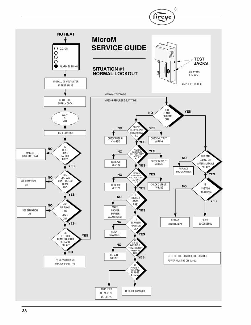
38
MAKE PROPERBURNER
ADJUSTMENT
DIDOPERATE
CONTROL LEDCOMEON?
DIDPTFI LED
COME ON AFTERSUITABLEDELAY?
DIDAIR FLOW
LEDCOME
O.C. ON
ALARM BLINKING
NO HEAT
INSTALL DC VOLTMETER
IN TEST JACKS
SHUT FUELSUPPLY COCK
WAIT5
MIN
RESET CONTROL
PROGRAMMER OR
MEC120 DEFECTIVE
MAKE ITCALL FOR HEAT
SEE SITUATION
SEE SITUATION
ISHEATBEING
CALLEDFOR?
ON?
#3
#2
YES
YES
YES
NO
SITUATION #1
NO
NO
NO
YES
YES
YES
YES
DID PTFI
IS
SYSTEMRUNNING?
ALIGN SCANNER
REPAIR WIRING
SUCCESSFULRESET
REPLACE PROGRAMMER
DIDFLAME
LED COMEON?
YES
MP100 4-7 SECONDS
MP230 PREPURGE DELAY TIME
NO YES
NORMAL LOCKOUT
NO
NO
NO
NO
NO
YES
AMPLIFIER
DEFECTIVE
OR MEC120 REPLACE SCANNER
REPEAT SITUATION #1
LED GO OFFAFTER SUITABLE
DELAY?
MicroMSERVICE GUIDE
TO RESET THE CONTROL THE CONTROL
POWER MUST BE ON. (L1-L2)
ISTHERE A
GOODFIRE?
ISPROPER
ACROSSS1 & S2
VOLTAGE
IS
WIRING &TERM. CONTACT
PRESSUREOK?
S1 S2
ISSCANNERPOSITION
OK?
PROPERPILOT VOLTAGE(120V) ACROSS
3, 2
YES
PROPERIGNITION
VOLTAGE (120V)ACROSS
4, 2
YES
PROPERMAIN VALVE
VOLTAGE (120V)ACROSS
5, 2
YES
CHECK FUSE IN CHASSIS
NO
CHECK OUTPUT
YES
WIRING
REPLACEMEC120
NO
REPLACEMEC120
NO
CHECK OUTPUT
YES
WIRING
CHECK OUTPUT
YES
WIRING
TESTJACKS
AMPLIFIER MODULE
ALL TYPES4-10 VDC
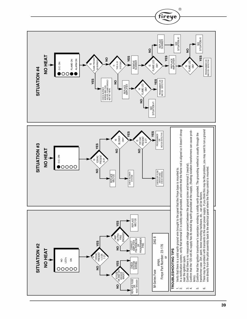
39
O.C
. ON
NO
YE
S
IS
PRES
ENT
8-
2?
O.C
. ON
ALA
RM
ON
YES
REPL
ACE
MEC
120
PROG
RAM
MER
ORM
C120
DEF
ECTI
VE
CHEC
K BL
OWER
SYST
EM
CHEC
K AI
R FL
OWSW
ITCH
AND
CH
ECK
WIR
ING
IS
BLOW
ERO
N?
IS12
0 VA
C PR
ESEN
T 6-
2?
FLA
ME
ON
YE
S
YE
S
NO
NO
SIT
UA
TIO
N #
2S
ITU
ATI
ON
#3
SIT
UA
TIO
N #
4
NO
HE
AT
NO
HE
AT
NO
YE
S
REPL
ACE
FUSE
ORRE
SET
BREA
KER
CHEC
KSY
STEM
WIR
ING
NO
YES
REPL
ACE
MEC
120
CORR
ECT
AMPL
IFIE
RPI
N PR
OBLE
M
IS F
USE
OK A
ND C
KT
BR
EAKE
RM
ADE?
NO
LED
’s
ON
YES
NON
O H
EA
T
IS
120V
ACPR
ESEN
T12
0VAC
AMP.
OR P
RO.
PINS
EN
GAGE
D
1-2
OR
ORPR
OGRA
MM
ERPI
NS
7-2?
REM
OVE
SCAN
NER
REPL
ACE
AMPL
IFIE
RNO
YE
S
NO
SEE
SITU
ATIO
N #1
RE
PLA
CE
AM
PLI
FIE
R
SEE
SITU
ATIO
N #1
PROG
RAM
MER
OR
DEFE
CTIV
E M
C120
REPL
ACE
SCAN
NER
SEE
SITU
ATIO
N #1
NO
YE
S
NO
YE
S
CHEC
K BU
RNER
WIR
ING
AND
FUEL
VALV
ES. F
LAM
E SH
OULD
NOT
BE T
HERE
.
ISFL
AME
LED
ON?
IS
THIS
A U
V
SYST
EM?
ISFL
AME
LED
ON?
YE
S
ISFL
AME
LED
ON?
ISFL
AME
PRES
ENT
IN B
URNE
R?
NO
TRO
UB
LES
HO
OTI
NG
TIP
S1.
Verif
y th
at th
ere
is a
sol
id e
arth
gro
und
wire
bro
ught
to th
e pa
nel t
hat t
he F
ireye
bas
e is
mou
nted
to.
2.In
a re
ctifi
catio
n sy
stem
, ver
ify th
at te
rmin
al S
1 is
sol
idly
ear
th g
roun
ded,
and
con
firm
that
the
flam
e ro
d is
alig
ned
so it
doe
sn’t
droo
p ne
ar th
e ig
nitio
n sp
ark.
3.Co
nfirm
that
ther
e is
no
mea
sura
ble
volta
ge p
rese
nt b
etw
een
the
grou
nd s
crew
and
term
inal
2 (n
eutra
l).4.
Conf
irm th
at th
e 12
0 vo
lt AC
sup
ply
has
its n
eutra
l leg
ear
th g
roun
ded
at th
e su
pply
, (flo
atin
g is
olat
ion
trans
form
ers
can
caus
e pr
ob-
lem
s).
5.Co
nfirm
that
the
igni
tion
trans
form
er’s
sec
onda
ry w
indi
ng is
sol
idly
ear
th g
roun
ded.
The
gro
undi
ng m
etho
d is
usu
ally
thro
ugh
the
trans
form
er c
ase.
Dirt
, pai
nt, l
oose
mou
ntin
g ha
rdw
are,
etc
., ca
n al
l be
fact
ors.
6.Th
ere
may
be
a pr
oble
m w
ith tr
ansi
ents
in th
e m
ain
pow
er s
uppl
y. If
you
thin
k th
is m
ay b
e th
e pr
oble
m, y
ou m
ay w
ant t
o ru
n a
grou
nd
wire
dire
ctly
from
the
pilo
t ass
embl
y ba
ck to
the
elec
trica
l pan
el w
here
the
Fire
ye c
ontro
l is
mou
nted
.
M-S
erie
s Fu
se
2AG
8 am
ps.
Fire
ye P
art N
umbe
r: 23
-176
or
PROG
RAM
MER
OR
DEFE
CTIV
E M
EC12
0
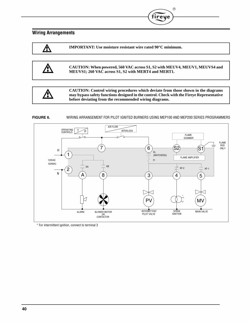
40
Wiring Arrangements
FIGURE 6. WIRING ARRANGEMENT FOR PILOT IGNITED BURNERS USING MEP100 AND MEP200 SERIES PROGRAMMERS
IMPORTANT: Use moisture resistant wire rated 90°C minimum.
CAUTION: When powered, 560 VAC across S1, S2 with MEUV4, MEUV1, MEUVS4 andMEUVS1; 260 VAC across S1, S2 with MERT4 and MERT1.
CAUTION: Control wiring procedures which deviate from those shown in the diagramsmay bypass safety functions designed in the control. Check with the Fireye Representativebefore deviating from the recommended wiring diagrams.
PV MV
S17
3 54
1
A
S2
INTERMITTENT MAIN VALVEBLOWER MOTORALARM
8
120VAC50/60Hz
T P
FLAME AMPLIFIER
SPARK
KL
KF-2 KF-1
PILOT VALVE IGNITION
*
H
N2
* For intermittent ignition, connect to terminal 3
FLAME SCANNER
ORCONTACTOR
OPERATINGCONTROLS
KBKA
(WATCHDOG)
AIR FLOW
INTERLOCK
F1
6FLAMEROD ONLY
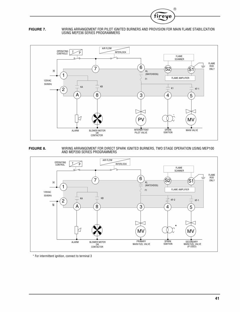
41
FIGURE 7. WIRING ARRANGEMENT FOR PILOT IGNITED BURNERS AND PROVISION FOR MAIN FLAME STABILIZATION USING MEP236 SERIES PROGRAMMERS
FIGURE 8. WIRING ARRANGEMENT FOR DIRECT SPARK IGNITED BURNERS, TWO STAGE OPERATION USING MEP100 AND MEP200 SERIES PROGRAMMERS
PV MV
S17
3 54
1
A
S2
INTERMITTENT MAIN VALVEBLOWER MOTORALARM
8
120VAC50/60Hz
T P
FLAME AMPLIFIER
SPARK
K1 KF-1
PILOT VALVE IGNITION
*
H
2
FLAME SCANNER
ORCONTACTOR
OPERATINGCONTROLS
KBKA
AIR FLOW
INTERLOCK
FLAMEROD ONLY
KL(WATCHDOG)
F1
6
MV MV
S17
3 54
1
A
S2
PRIMARY SECONDARYBLOWER MOTERALARM
8
120VAC50/60Hz
T P
FLAME AMPLIFIER
SPARK
KF-2 KF-1
MAIN FUEL VALVE IGNITION
H
N2
FLAME SCANNER
MAIN FUEL VALVE(IF USED)
OR CONTACTOR
KA KB
OPERATING CONTROL
AIR FLOW
INTERLOCK
* For intermittent ignition, connect to terminal 3
*
FLAMEROD ONLY
KL(WATCHDOG)
F1
6
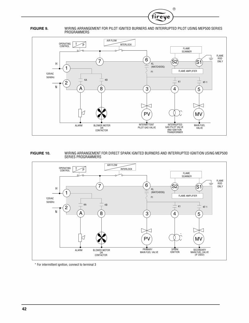
42
FIGURE 9. WIRING ARRANGEMENT FOR PILOT IGNITED BURNERS AND INTERRUPTED PILOT USING MEP500 SERIES PROGRAMMERS
FIGURE 10. WIRING ARRANGEMENT FOR DIRECT SPARK IGNITED BURNERS AND INTERRUPTED IGNITION USING MEP500 SERIES PROGRAMMERS
PV MV
S17
3 54
1
A
S2
INTERMITTENT BLOWER MOTERALARM
8
120VAC50/60Hz
T P
FLAME AMPLIFIER
INTERRUPTED
K1 KF-1
PILOT GAS VALVE
H
N2
FLAME SCANNER
MAIN FUEL OR
CONTACTORVALVE
AND IGNITIONTRANSFORMER
GAS PILOT VALVE
OPERATING CONTROL
KA KB
AIR FLOW
INTERLOCK
FLAMEROD ONLY
KL(WATCHDOG)
F1
6
PV MV
S17
3 54
1
A
S2
PRIMARY SECONDARY BLOWER MOTORALARM
8
120VAC50/60Hz
T P
FLAME AMPLIFIER
SPARK
K1 KF-1
MAIN FUEL VALVE IGNITION
*
H
N2
* For intermittent ignition, connect to terminal 3
FLAME SCANNER
ORCONTACTOR
MAIN FUEL VALVE(IF USED)
OPERATING CONTROL
KA KB
AIR FLOW
INTERLOCK
FLAMEROD ONLY
KL(WATCHDOG)
F1
6
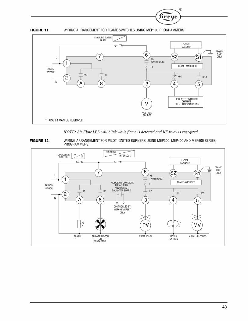
43
FIGURE 11. WIRING ARRANGEMENT FOR FLAME SWITCHES USING MEP100 PROGRAMMERS
NOTE: Air Flow LED will blink while flame is detected and KF relay is energized.
FIGURE 12. WIRING ARRANGEMENT FOR PILOT IGNITED BURNERS USING MEP300, MEP400 AND MEP600 SERIES PROGRAMMERS.
V
S17
3 54
1
A
S2
VOLTAGE
8
120VAC50/60Hz
FLAME AMPLIFIER
KF-2 KF-1
H
N2
FLAME SCANNER
ENABLE/DISABLE
KA KB
SOURCE
ISOLATED SWITCHEDOUTPUTS
REFER TO LOAD RATINGOUTPUTS
INPUT
* FUSE F1 CAN BE REMOVED
FLAMEROD ONLY
KL(WATCHDOG)
F1
6
PV MV
S17
3 54
1
A
S2
PILOT VALVE BLOWER MOTORALARM
8
120VAC50/60Hz
T P
FLAME AMPLIFIER
SPARK
KI KF
IGNITION
H
N2
FLAME SCANNER
ORCONTACTOR
MAIN FUEL VALVE
OPERATING CONTROL
KA KB
AIR FLOW
INTERLOCK
FLAMEROD ONLY
KL(WATCHDOG)
F1
6
KP
MODULATE CONTACTS
MED8/MED9DAUGHTER BOARD
LOCATED ON
CONTROLLED BYMEP696/MEP697
ONLY
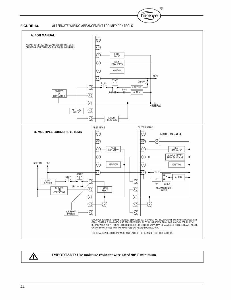
44
FIGURE 13. ALTERNATE WIRING ARRANGEMENT FOR MEP CONTROLS
S2
3
5
4
1
MAIN
IGNITION
7
8
2
A
6
STOP
PILOT
S1
START
LIMIT SW
FUEL VALVE
ALARM
ON-OFF
HOT
NEUTRAL
LR-1LR-2
LATCH
AIR FLOWSWITCH
A. FOR MANUAL
A START-STOP STATION MAY BE ADDED TO REQUIRE OPERATOR START-UP EACH TIME THE BURNER FIRES.
S2
3
5
4
1
IGNITION
7
8
2
A
6
PILOT
S1B. MULTIPLE BURNER SYSTEMS
S2
3
5
4
1
IGNITION
7
8
2
A
6
PILOT
S1
LIMIT
R
MANUAL RESET
MAIN GAS VALVE
ALARM
S.P.D.T.RA
ALARM SILENCESWITCH
G
R
STOPSTART
LR-1
AIR FLOW
BLOWEROR
LATCH
HOTNEUTRAL
MULTIPLE BURNER SYSTEMS UTILIZING SEMI-AUTOMATIC OPERATION INCORPORATE THE FIREYE MODULAR MI-CROM CONTROLS IN A CASCADING SEQUENCE WHEN PILOT #1 IS PROVEN. TRIAL FOR IGNITION FOR PILOT #2 BEGINS. WHEN ALL PILOTS ARE PROVEN THE SAFETY SHUTOFF VALVE MAY BE MANUALLY OPENED. FLAME FAILURE OF ANY BURNER WILL TRIP THE MAIN FUEL VALVE AND SOUND ALARM.
THE TOTAL CONNECTED LOAD MUST NOT EXCEED THE RATING OF THE FIRST CONTROL.
VALVE
RELAY COIL
MAIN GAS VALVE
GAS VALVE
RELAY
GAS VALVE
SWITCH
SWITCH
BLOWER OR
CONTACTOR
FIRST STAGE SECOND STAGE
CONTACTOR
IMPORTANT: Use moisture resistant wire rated 90°C minimum.
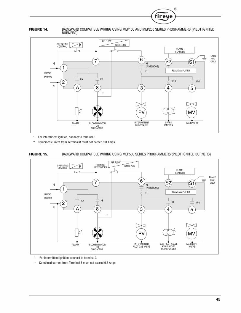
45
FIGURE 14. BACKWARD COMPATIBLE WIRING USING MEP100 AND MEP200 SERIES PROGRAMMERS (PILOT IGNITED BURNERS).
FIGURE 15. BACKWARD COMPATIBLE WIRING USING MEP500 SERIES PROGRAMMERS (PILOT IGNITED BURNERS)
PV MV
S17
3 54
1
A
S2
INTERMITTENT MAIN VALVEBLOWER MOTORALARM
8
120VAC50/60Hz
T P
FLAME AMPLIFIER
SPARK
KF-2 KF-1
PILOT VALVE IGNITION
*
H
N2
* For intermittent ignition, connect to terminal 3
FLAME SCANNER
ORCONTACTOR
OPERATINGCONTROL
KBKA
**
** Combined current from Terminal 8 must not exceed 9.8 Amps
AIR FLOW
INTERLOCK
FLAMEROD ONLY
KL(WATCHDOG)
F1
6
PV MV
S17
3 54
1
A
S2
INTERMITTENT MAIN FUEL
RUNNING
BLOWER MOTORALARM
8
120VAC50/60Hz
T P
FLAME AMPLIFIER
GAS PILOT VALVE
K1 KF-1
PILOT GAS VALVE AND IGNITION
*
H
N2
FLAME SCANNER
ORCONTACTOR
VALVETRANSFORMER
OPERATING CONTROL
**
INTERLOCKS
KBKA
* For intermittent ignition, connect to terminal 3
AIR FLOW
INTERLOCK
FLAMEROD ONLY
KL(WATCHDOG)
F1
6
** Combined current from Terminal 8 must not exceed 9.8 Amps
46
SUGGESTED GROUNDING RULESThe MicroM system, being microprocessor based, requires a ground system that provides a zero-voltage reference. The voltage measured from L2 to all other terminals except L1 should be 0 volts.
1. The most effective ground is to run the ground wire in the same raceway as the hot and neutralfrom the main distribution service panel (not intermediate sub-panels) to the burner controlpanel and insure that this ground wire is well bonded to the control panel.
2. The wiring base of the MicroM must have earth ground providing a connection between the sub-base and the control panel or the burner.
3. The earth ground wire must be capable of conducting the current to blow the 20A fuse in eventof an internal short circuit. A number 14 AWG copper conductor is adequate, wide straps orbrackets are preferred rather than lead wires.
4. The ground path needs to be low impedance (less than 1 ohm) to the equipment frame which inturn needs a low impedance to earth ground. For a ground path to be low impedance at RF fre-quencies, the connection must be made with minimum length conductors having maximum sur-face areas.
5. All connections should be free of nonconductive coatings and protected against rust.6. Utilizing conduit as a means of providing a ground must be avoided. 7. Installing ground rods at the burner control panel defeats the purpose of a single point ground as
described above and could also present a safety hazard.
INSTALLATIONDo not run high voltage ignition transformer wires in the same conduit with flame detection wiring.
Do not run scanner wires in a conduit with line voltage circuits.
Ensure the frame of the ignition transformer is securely connected to control panel frame or prefera-bly the burner frame.
The MicroM chassis (MEC120) contains a transient suppressing device connected internally acrosshot and neutral and then to the internal bracket. For this to be effective the chassis must be screwedsecurely into the wiring subbase.
REMOTE DISPLAYWhen the ED510 is to be remotely mounted on the front of the control panel, the ED580 cable mustcontain a ferrite core, currently supplied by Fireye with the cable. The cable end with the ferrite coremust be mounted at the control end. High frequency currents flow more to the surface of the conduc-tor. The 60 Hz ground system, properly designed, has sufficient low-impedance at 60 Hz to maintainall metal surfaces at the same ground reference. But, this same system is unable to provide this athigher frequencies, because of the increased impedance caused by the ‘skin effect’. The purpose ofthe ferrite core is to provide a high-impedance at these higher frequencies and absorb or block thisunwanted energy.
Care must be taken not to route the ED580 cable in close proximity to any starter motor contactorslocated in the control panel or across any high voltage ignition wires. Refer to Fireye bulletin E-8002for proper installation.
47
COMMUNICATIONSWhen interfacing Fireye controls to a communication system, be it an E500, PLC or other micropro-cessor based device, ferrite cores should also be utilized. Proper twisted shielded pair cable must beutilized. In a multi-drop system, the shields should be tied together within a cabinet and not to anyground point. The shield at the source end of the cable of the multi-drop connection can then be ter-minated to ground. Source end is defined as the originating end of the communication system
Care must be taken not to route communication cables in close proximity to any starter motor con-tactors located in the control panel or across any high voltage ignition wires. Refer to Fireye bulletinE-8002 for proper installation.
SCANNERSThe armored cable supplied with the Ultra-Violet and Infrared scanners should be connected toequipment by means of a good mechanical connection such as a conduit fitting. It may be necessaryto utilize heat insulator (P/N 35-69) to isolate the sensing end of the scanner from boiler ground.Care must be taken not to route the scanner cable across the high voltage ignition cable. The highenergy ignition cable should be checked periodically for cracking, connections and aging.
In applications using flame rod units and the MERT amplifier, it may be beneficial to route a sepa-rate return wire from the S1 terminal to the flame rod assembly. This will minimize the effects oftransient currents flowing into the MicroM.
In all cases, scanner wires should be routed in separate conduit and not joined with any high voltageAC or ignition cables.
MAINTENANCEPeriodically, the spark electrode should be inspected for proper gapping and cracked ceramics. Atignition time, the high energy from the ignition transformer will attempt to conduct to the point ofleast resistance and with an improper spark gap, where the conduction takes place will no longer becontrolled.
The VA rating of the control transformer must be sized to handle the inrush currents of the pilot sole-noid and ignition transformer at PTFI and then the inrush currents of the main fuel valve assembly atMTFI time.
Inspect neatness of wiring in junction boxes and cabinets. It is best to have connections short anddirect and also not having wires bunched up and tied off. Also, connections should be periodicallyinspected for tightness and corrosion.
INSTALLATION - UV SCANNERSWhere possible, obtain the burner manufacturer’s instructions for mounting the scanner. This infor-mation is available for most standard burners. The scanner mounting should comply with the follow-ing general instructions:
1. Position the UV1A, UV2 scanner within 30 inches of the flame to be monitored; the 45UV5within 72 inches, closer if possible.
2. Select a scanner location that will remain within the ambient temperature limits of the UV Scan-ner. If cooling is required, use an insulating coupling (Fireye P/N 35-69 for UV1A, UV2 Scan-ners, P/N 35-127-1 for 45UV5) to reduce conducted heat.
3. The UVlA, UV2, 45UV5 Scanners are designed to seal off the sight pipe up to 1 PSI pressure.Higher furnace pressures should be sealed off. To seal off positive furnace pressure up to 100PSI for UV1A, UV2 Scanners, install a quartz window coupling (#60-1257) For 45UV5 Scan-ners, use #60-1199 coupling. Add cooling air to reduce the scanner sight pipe temperature.
4. Install the scanner on a standard NPT pipe (UV1A: 1/2", UV2: 3/8", 45UV5: 1") whose positionis rigidly fixed. If the scanner mounting pipe sights through the refractory, do not extend it more
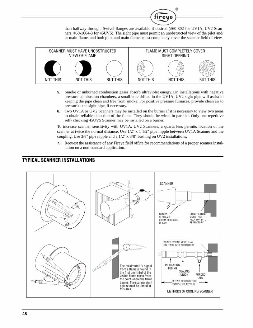
48
than halfway through. Swivel flanges are available if desired (#60-302 for UV1A, UV2 Scan-ners, #60-1664-3 for 45UV5). The sight pipe must permit an unobstructed view of the pilot and/or main flame, and both pilot and main flames must completely cover the scanner field of view.
5. Smoke or unburned combustion gases absorb ultraviolet energy. On installations with negativepressure combustion chambers, a small hole drilled in the UV1A, UV2 sight pipe will assist inkeeping the pipe clean and free from smoke. For positive pressure furnaces, provide clean air topressurize the sight pipe, if necessary.
6. Two UV1A or UV2 Scanners may be installed on the burner if it is necessary to view two areasto obtain reliable detection of the flame. They should be wired in parallel. Only one repetitiveself- checking 45UV5 Scanner may be installed on a burner.
To increase scanner sensitivity with UV1A, UV2 Scanners, a quartz lens permits location of thescanner at twice the normal distance. Use 1/2" x 1 1/2" pipe nipple between UV1A Scanner and thecoupling. Use 3/8" pipe nipple and a 1/2" x 3/8" bushing on UV2 installations.
7. Request the assistance of any Fireye field office for recommendations of a proper scanner instal-lation on a non-standard application.
TYPICAL SCANNER INSTALLATIONS
SCANNER MUST HAVE UNOBSTRUCTEDVIEW OF FLAME
NOT THIS NOT THIS BUT THIS
FLAME MUST COMPLETELY COVERSIGHT OPENING
NOT THIS NOT THIS BUT THIS
The maximum UV signal from a flame is found in the first one-third of the visible flame taken from the point where the flame begins. The scanner sight pipe should be aimed at this area.
DO NOT EXTENDMORE THANHALF-WAY INTOREFRACTORY
SCANNER
FORCEDCLEAN AIR(FROM DISCHARGEOF FAN)
METHODS OF COOLING SCANNER
INSULATINGTUBING
SEALING UNION FORCED
AIREXTEND SIGHTING TUBE6”(152.4) OR 8”(203.2)
DO NOT EXTEND MORE THANHALF-WAY INTO REFRACTORY
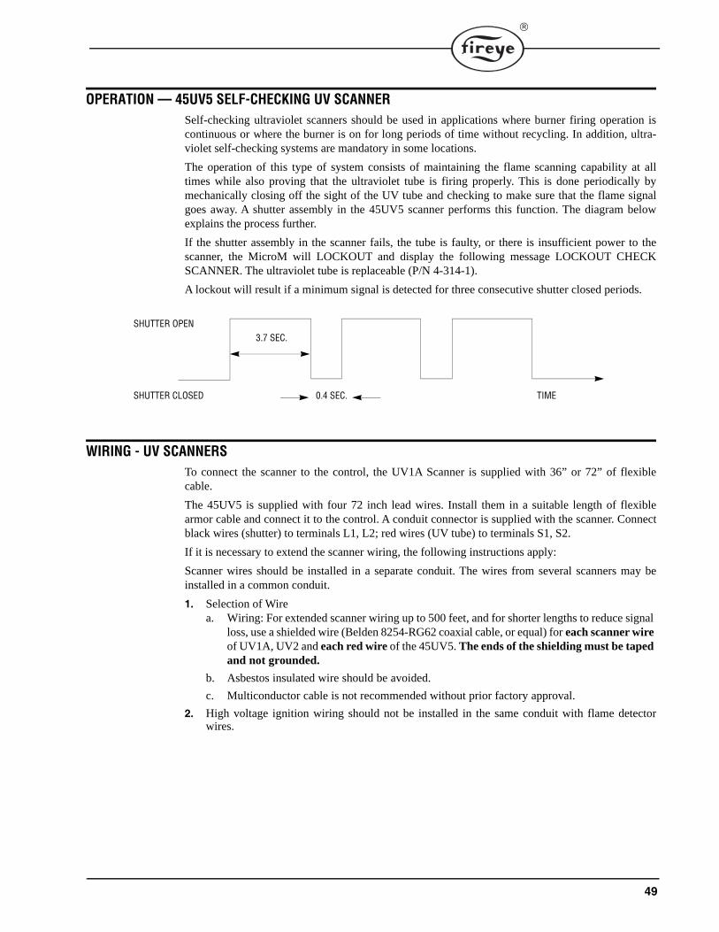
49
OPERATION — 45UV5 SELF-CHECKING UV SCANNERSelf-checking ultraviolet scanners should be used in applications where burner firing operation iscontinuous or where the burner is on for long periods of time without recycling. In addition, ultra-violet self-checking systems are mandatory in some locations.
The operation of this type of system consists of maintaining the flame scanning capability at alltimes while also proving that the ultraviolet tube is firing properly. This is done periodically bymechanically closing off the sight of the UV tube and checking to make sure that the flame signalgoes away. A shutter assembly in the 45UV5 scanner performs this function. The diagram belowexplains the process further.
If the shutter assembly in the scanner fails, the tube is faulty, or there is insufficient power to thescanner, the MicroM will LOCKOUT and display the following message LOCKOUT CHECKSCANNER. The ultraviolet tube is replaceable (P/N 4-314-1).
A lockout will result if a minimum signal is detected for three consecutive shutter closed periods.
WIRING - UV SCANNERSTo connect the scanner to the control, the UV1A Scanner is supplied with 36” or 72” of flexiblecable.
The 45UV5 is supplied with four 72 inch lead wires. Install them in a suitable length of flexiblearmor cable and connect it to the control. A conduit connector is supplied with the scanner. Connectblack wires (shutter) to terminals L1, L2; red wires (UV tube) to terminals S1, S2.
If it is necessary to extend the scanner wiring, the following instructions apply:
Scanner wires should be installed in a separate conduit. The wires from several scanners may beinstalled in a common conduit.
1. Selection of Wirea. Wiring: For extended scanner wiring up to 500 feet, and for shorter lengths to reduce signal
loss, use a shielded wire (Belden 8254-RG62 coaxial cable, or equal) for each scanner wire of UV1A, UV2 and each red wire of the 45UV5. The ends of the shielding must be taped and not grounded.
b. Asbestos insulated wire should be avoided.
c. Multiconductor cable is not recommended without prior factory approval.
2. High voltage ignition wiring should not be installed in the same conduit with flame detectorwires.
SHUTTER OPEN
SHUTTER CLOSED
3.7 SEC.
0.4 SEC. TIME
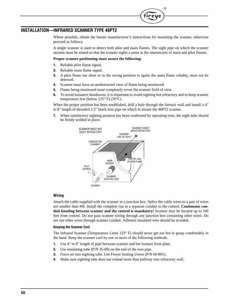
50
INSTALLATION—INFRARED SCANNER TYPE 48PT2Where possible, obtain the burner manufacturer’s instructions for mounting the scanner, otherwiseproceed as follows:
A single scanner is used to detect both pilot and main flames. The sight pipe on which the scannermounts must be aimed so that the scanner sights a point at the intersection of main and pilot flames.
Proper scanner positioning must assure the following:
1. Reliable pilot flame signal.
2. Reliable main flame signal.3. A pilot flame too short or in the wrong position to ignite the main flame reliably, must not be
detected.4. Scanner must have an unobstructed view of flame being monitored.5. Flame being monitored must completely cover the scanner field of view.6. To avoid nuisance shutdowns, it is important to avoid sighting hot refractory and to keep scanner
temperature low (below 125° F) (50°C).
When the proper position has been established, drill a hole through the furnace wall and install a 4"to 8" length of threaded 1/2" black iron pipe on which to mount the 48PT2 scanner.
7. When satisfactory sighting position has been confirmed by operating tests, the sight tube shouldbe firmly welded in place.
Wiring
Attach the cable supplied with the scanner to a junction box. Splice the cable wires to a pair of wiresnot smaller than #l8. Install the complete run in a separate conduit to the control. Continuous con-duit bonding between scanner and the control is mandatory! Scanner may be located up to 100feet from control. Do not pass scanner wiring through any junction box containing other wires. Donot run other wires through scanner conduit. Asbestos insulated wire should be avoided.
Keeping the Scanner Cool
The Infrared Scanner (Temperature Limit 125° F) should never get too hot to grasp comfortably inthe hand. Keep the scanner cool by one or more of the following methods.
1. Use 6" to 8" length of pipe between scanner and hot furnace front plate.
2. Use insulating tube (P/N 35-69) on the end of the iron pipe.3. Force air into sighting tube. Use Fireye Sealing Union (P/N 60-801).4. Make sure sighting tube does not extend more than halfway into refractory wall.
CENTER LINEOF MAIN FLAME
SCANNERLINE-OF-SIGHT
SCANNER TARGETABOVE REFRACTORY
COMBUSTIONCHAMBER
PILOTBURNER
SCANNER
SCANNERSIGHTING TUBE
MAINBURNER
SCANNER MUST NOTSIGHT REFRACTORY
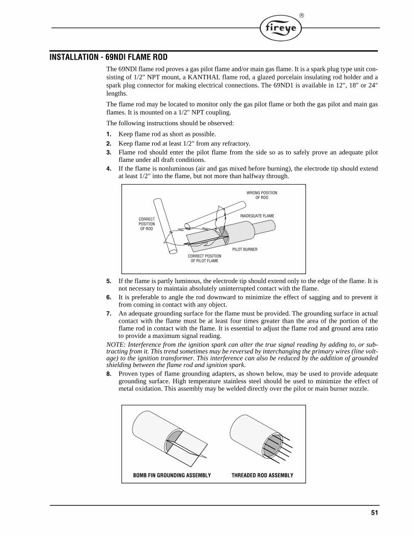
51
INSTALLATION - 69NDl FLAME RODThe 69NDl flame rod proves a gas pilot flame and/or main gas flame. It is a spark plug type unit con-sisting of 1/2" NPT mount, a KANTHAL flame rod, a glazed porcelain insulating rod holder and aspark plug connector for making electrical connections. The 69ND1 is available in 12", 18" or 24"lengths.
The flame rod may be located to monitor only the gas pilot flame or both the gas pilot and main gasflames. It is mounted on a 1/2" NPT coupling.
The following instructions should be observed:
1. Keep flame rod as short as possible.
2. Keep flame rod at least 1/2" from any refractory.3. Flame rod should enter the pilot flame from the side so as to safely prove an adequate pilot
flame under all draft conditions.4. If the flame is nonluminous (air and gas mixed before burning), the electrode tip should extend
at least 1/2" into the flame, but not more than halfway through.
5. If the flame is partly luminous, the electrode tip should extend only to the edge of the flame. It isnot necessary to maintain absolutely uninterrupted contact with the flame.
6. It is preferable to angle the rod downward to minimize the effect of sagging and to prevent itfrom coming in contact with any object.
7. An adequate grounding surface for the flame must be provided. The grounding surface in actualcontact with the flame must be at least four times greater than the area of the portion of theflame rod in contact with the flame. It is essential to adjust the flame rod and ground area ratioto provide a maximum signal reading.
NOTE: Interference from the ignition spark can alter the true signal reading by adding to, or sub-tracting from it. This trend sometimes may be reversed by interchanging the primary wires (line volt-age) to the ignition transformer. This interference can also be reduced by the addition of groundedshielding between the flame rod and ignition spark.8. Proven types of flame grounding adapters, as shown below, may be used to provide adequate
grounding surface. High temperature stainless steel should be used to minimize the effect ofmetal oxidation. This assembly may be welded directly over the pilot or main burner nozzle.
WRONG POSITIONOF ROD
INADEQUATE FLAME
PILOT BURNER
CORRECT POSITIONOF PILOT FLAME
CORRECTPOSITIONOF ROD
BOMB FIN GROUNDING ASSEMBLY THREADED ROD ASSEMBLY
52
MAINTENANCE
Type 48PT2 Infrared and Type UV1A, UV2 and 45UV5 Ultraviolet Scanners
The viewing area of the scanner must be kept clean. Even a small amount of contamination willreduce the flame signal reaching the detector by a measurable amount. Wipe the viewing area rou-tinely using a soft cloth dampened with concentrated detergent.
— Type 48PT2 Scanners include a replaceable #4-263-1 Firetron cell.
— Type 45UV5 Scanners include a replaceable #4-314-1 UV tube.
Type 69ND1 Flame Rod
The flame rod and its insulator should be kept clean by washing routinely with soap and water. Rodsshould be routinely replaced as they oxidize.
Flame Signal Strength
Routine observation of the flame signal strength will forewarn any deterioration in the capability ofthe flame detector or its application.
Contacts
There are no accessible contacts in the MicroM. Where contacts are used, their design assures longtrouble-free life when the load circuits are maintained within the published load ratings.
Humidity
In areas of high humidity, the control chassis should be removed and placed in a dry atmospherewhen the system is expected to be out of service for an extended period.
Periodic Safety Check
It is recommended that a procedure be established to test the complete flame safeguard system atleast once a month. This test should verify the proper operation of all limit switches and safety inter-locks as well as flame failure protection and fuel safety shutoff valve tightness.
Rotation
It is recommended that control and scanner units purchased as spares be installed periodically toensure proper operation.
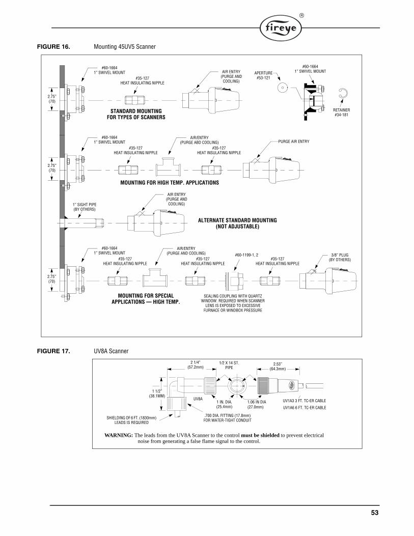
53
FIGURE 16. Mounting 45UV5 Scanner
FIGURE 17. UV8A Scanner
2.75”(70)
#60-16641” SWIVEL MOUNT
#35-127HEAT INSULATING NIPPLE
STANDARD MOUNTINGFOR TYPES OF SCANNERS
AIR ENTRY(PURGE AND
COOLING)
#60-16641” SWIVEL MOUNT
#35-127HEAT INSULATING NIPPLE
MOUNTING FOR HIGH TEMP. APPLICATIONS
PURGE AIR ENTRYAIR/ENTRY
(PURGE ABD COOLING)#35-127
HEAT INSULATING NIPPLE
1” SIGHT PIPE(BY OTHERS)
AIR ENTRY(PURGE AND
COOLING)
ALTERNATE STANDARD MOUNTING(NOT ADJUSTABLE)
#60-16641” SWIVEL MOUNT
#35-127HEAT INSULATING NIPPLE
MOUNTING FOR SPECIALAPPLICATIONS — HIGH TEMP.
3/8” PLUG(BY OTHERS)
AIR/ENTRY(PURGE AND COOLING)
#35-127HEAT INSULATING NIPPLE
#35-127HEAT INSULATING NIPPLE
#60-1199-1, 2
SEALING COUPLING WITH QUARTZWINDOW. REQUIRED WHEN SCANNER
LENS IS EXPOSED TO EXCESSIVEFURNACE OR WINDBOX PRESSURE
APERTURE#53-121
#60-16641” SWIVEL MOUNT
RETAINER#34-181
2.75”(70)
2.75”(70)
2 1/4”(57.2mm)
UV1A3 3 FT. TC-ER CABLE
UV1A6 6 FT. TC-ER CABLE
1 1/2”(38.1MM)
UV8A
1/2 X 14 ST.PIPE
1 IN. DIA.(25.4mm)
2.53”(64.3mm)
SHIELDING OF 6 FT. (1830mm)LEADS IS REQUIRED
.700 DIA. FITTING (17.8mm)FOR WATER-TIGHT CONDUIT
WARNING: The leads from the UV8A Scanner to the control must be shielded to prevent electrical noise from generating a false flame signal to the control.
1.06 IN DIA(27.0mm)
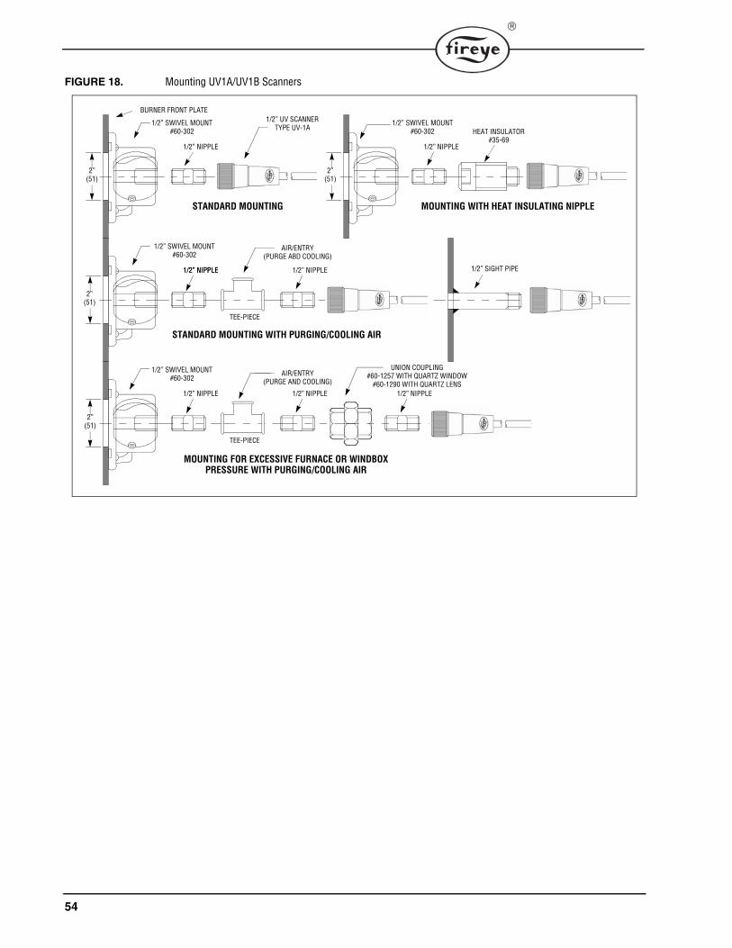
54
FIGURE 18. Mounting UV1A/UV1B Scanners
UNION COUPLING#60-1257 WITH QUARTZ WINDOW
#60-1290 WITH QUARTZ LENS
2”(51)
1/2” NIPPLE
HEAT INSULATOR#35-69
1/2” SWIVEL MOUNT#60-302
MOUNTING WITH HEAT INSULATING NIPPLE
1/2” NIPPLE
1/2” SWIVEL MOUNT#60-302
STANDARD MOUNTING
BURNER FRONT PLATE1/2” UV SCANNER
TYPE UV-1A
1/2” NIPPLE
1/2” SWIVEL MOUNT#60-302
STANDARD MOUNTING WITH PURGING/COOLING AIR
1/2” NIPPLE 1/2” NIPPLE
TEE-PIECE
1/2” NIPPLE
1/2” SWIVEL MOUNT#60-302
MOUNTING FOR EXCESSIVE FURNACE OR WINDBOXPRESSURE WITH PURGING/COOLING AIR
1/2” NIPPLE
TEE-PIECE
1/2” NIPPLE
AIR/ENTRY(PURGE ABD COOLING)
1/2” SIGHT PIPE
AIR/ENTRY(PURGE AND COOLING)
2”(51)
2”(51)
2”(51)
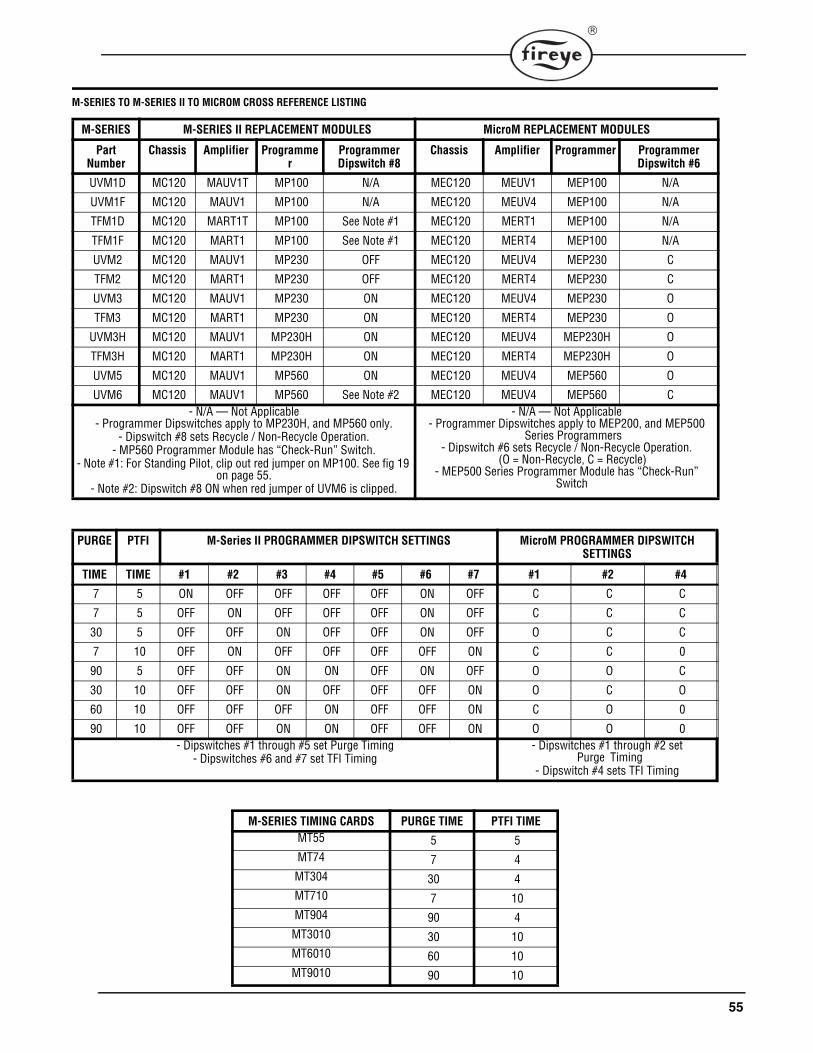
55
M-SERIES TO M-SERIES II TO MICROM CROSS REFERENCE LISTING
M-SERIES M-SERIES II REPLACEMENT MODULES MicroM REPLACEMENT MODULES
Part Number
Chassis Amplifier Programmer
ProgrammerDipswitch #8
Chassis Amplifier Programmer ProgrammerDipswitch #6
UVM1D MC120 MAUV1T MP100 N/A MEC120 MEUV1 MEP100 N/A
UVM1F MC120 MAUV1 MP100 N/A MEC120 MEUV4 MEP100 N/A
TFM1D MC120 MART1T MP100 See Note #1 MEC120 MERT1 MEP100 N/A
TFM1F MC120 MART1 MP100 See Note #1 MEC120 MERT4 MEP100 N/A
UVM2 MC120 MAUV1 MP230 OFF MEC120 MEUV4 MEP230 C
TFM2 MC120 MART1 MP230 OFF MEC120 MERT4 MEP230 C
UVM3 MC120 MAUV1 MP230 ON MEC120 MEUV4 MEP230 O
TFM3 MC120 MART1 MP230 ON MEC120 MERT4 MEP230 O
UVM3H MC120 MAUV1 MP230H ON MEC120 MEUV4 MEP230H O
TFM3H MC120 MART1 MP230H ON MEC120 MERT4 MEP230H O
UVM5 MC120 MAUV1 MP560 ON MEC120 MEUV4 MEP560 O
UVM6 MC120 MAUV1 MP560 See Note #2 MEC120 MEUV4 MEP560 C- N/A — Not Applicable
- Programmer Dipswitches apply to MP230H, and MP560 only.- Dipswitch #8 sets Recycle / Non-Recycle Operation.
- MP560 Programmer Module has “Check-Run” Switch.- Note #1: For Standing Pilot, clip out red jumper on MP100. See fig 19
on page 55.- Note #2: Dipswitch #8 ON when red jumper of UVM6 is clipped.
- N/A — Not Applicable- Programmer Dipswitches apply to MEP200, and MEP500
Series Programmers- Dipswitch #6 sets Recycle / Non-Recycle Operation.
(O = Non-Recycle, C = Recycle)- MEP500 Series Programmer Module has “Check-Run”
Switch.
PURGE PTFI M-Series II PROGRAMMER DIPSWITCH SETTINGS MicroM PROGRAMMER DIPSWITCH SETTINGS
TIME TIME #1 #2 #3 #4 #5 #6 #7 #1 #2 #4
7 5 ON OFF OFF OFF OFF ON OFF C C C
7 5 OFF ON OFF OFF OFF ON OFF C C C
30 5 OFF OFF ON OFF OFF ON OFF O C C
7 10 OFF ON OFF OFF OFF OFF ON C C 0
90 5 OFF OFF ON ON OFF ON OFF O O C
30 10 OFF OFF ON OFF OFF OFF ON O C O
60 10 OFF OFF OFF ON OFF OFF ON C O 0
90 10 OFF OFF ON ON OFF OFF ON O O 0- Dipswitches #1 through #5 set Purge Timing
- Dipswitches #6 and #7 set TFI Timing- Dipswitches #1 through #2 set
Purge Timing- Dipswitch #4 sets TFI Timing
M-SERIES TIMING CARDS PURGE TIME PTFI TIMEMT55 5 5MT74 7 4MT304 30 4MT710 7 10MT904 90 4
MT3010 30 10MT6010 60 10MT9010 90 10
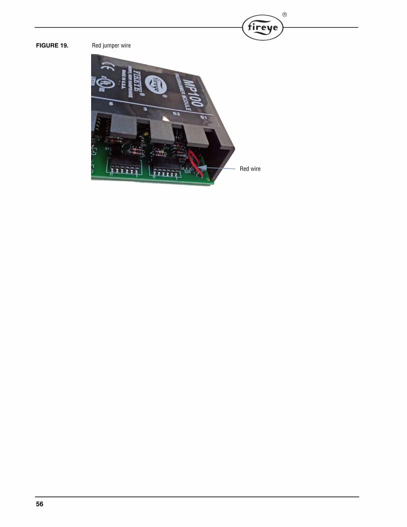
56
FIGURE 19. Red jumper wire
Red wire

57
NOTICEWhen Fireye products are combined with equipment manufactured by others and/or integrated intosystems designed or manufactured by others, the Fireye warranty, as stated in its General Terms andConditions of Sale, pertains only to the Fireye products and not to any other equipment or to the com-bined system or its overall performance.
WARRANTIESFIREYE guarantees for one year from the date of installation or 18 months from date of manufactureof its products to replace, or, at its option, to repair any product or part thereof (except lamps and pho-tocells) which is found defective in material or workmanship or which otherwise fails to conform tothe description of the product on the face of its sales order. THE FOREGOING IS IN LIEU OFALL OTHER WARRANTIES AND FIREYE MAKES NO WARRANTY OF MERCHANTABI-LITY OR ANY OTHER WARRANTY, EXPRESS OR IMPLIED. Except as specifically stated inthese general terms and conditions of sale, remedies with respect to any product or part number manu-factured or sold by Fireye shall be limited exclusively to the right to replacement or repair as aboveprovided. In no event shall Fireye be liable for consequential or special damages of any nature thatmay arise in connection with such product or part.
FIREYE MC-50003 Manchester Road MAY 10 2017Derry, New Hampshire 03038 USA Supersedes JUNE 9, 2015www.fireye.com