Embed Size (px)
DESCRIPTION
pdf from instructables firework controler diy
Citation preview
http://www.instructables.com/id/Fireworks-Controller/
Home Sign Up! Explore Community Submit
All Art Craft Food Games Green Home Kids Life Music Offbeat Outdoors Pets Ride Science Sports Tech
Fireworks Controllerby systemf92 on July 9, 2008
Table of Contents
intro: Fireworks Controller . . . . . . . . . . . . . . . . . . . . . . . . . . . . . . . . . . . . . . . . . . . . . . . . . . . . . . . . . . . . . . . . . . . . . . . . . . . . . . . . . . . . . . . . . . . . . . . . . . . . . . 2
step 1: Parts . . . . . . . . . . . . . . . . . . . . . . . . . . . . . . . . . . . . . . . . . . . . . . . . . . . . . . . . . . . . . . . . . . . . . . . . . . . . . . . . . . . . . . . . . . . . . . . . . . . . . . . . . . . . . . . . 2
From Jameco Electronics . . . . . . . . . . . . . . . . . . . . . . . . . . . . . . . . . . . . . . . . . . . . . . . . . . . . . . . . . . . . . . . . . . . . . . . . . . . . . . . . . . . . . . . . . . . . . . . . . . . 2
From Parts Express . . . . . . . . . . . . . . . . . . . . . . . . . . . . . . . . . . . . . . . . . . . . . . . . . . . . . . . . . . . . . . . . . . . . . . . . . . . . . . . . . . . . . . . . . . . . . . . . . . . . . . . 2
From Michaels . . . . . . . . . . . . . . . . . . . . . . . . . . . . . . . . . . . . . . . . . . . . . . . . . . . . . . . . . . . . . . . . . . . . . . . . . . . . . . . . . . . . . . . . . . . . . . . . . . . . . . . . . . . 2
Other Parts . . . . . . . . . . . . . . . . . . . . . . . . . . . . . . . . . . . . . . . . . . . . . . . . . . . . . . . . . . . . . . . . . . . . . . . . . . . . . . . . . . . . . . . . . . . . . . . . . . . . . . . . . . . . . . . . 2
step 2: Hardware needed . . . . . . . . . . . . . . . . . . . . . . . . . . . . . . . . . . . . . . . . . . . . . . . . . . . . . . . . . . . . . . . . . . . . . . . . . . . . . . . . . . . . . . . . . . . . . . . . . . . . . . . 4
Woodworking Tools . . . . . . . . . . . . . . . . . . . . . . . . . . . . . . . . . . . . . . . . . . . . . . . . . . . . . . . . . . . . . . . . . . . . . . . . . . . . . . . . . . . . . . . . . . . . . . . . . . . . . . . . . . 4
Electronics Tools . . . . . . . . . . . . . . . . . . . . . . . . . . . . . . . . . . . . . . . . . . . . . . . . . . . . . . . . . . . . . . . . . . . . . . . . . . . . . . . . . . . . . . . . . . . . . . . . . . . . . . . . . . . . 4
step 3: Designing a template . . . . . . . . . . . . . . . . . . . . . . . . . . . . . . . . . . . . . . . . . . . . . . . . . . . . . . . . . . . . . . . . . . . . . . . . . . . . . . . . . . . . . . . . . . . . . . . . . . . . 5
File Downloads . . . . . . . . . . . . . . . . . . . . . . . . . . . . . . . . . . . . . . . . . . . . . . . . . . . . . . . . . . . . . . . . . . . . . . . . . . . . . . . . . . . . . . . . . . . . . . . . . . . . . . . . . . . . . 5
step 4: Cut the wood . . . . . . . . . . . . . . . . . . . . . . . . . . . . . . . . . . . . . . . . . . . . . . . . . . . . . . . . . . . . . . . . . . . . . . . . . . . . . . . . . . . . . . . . . . . . . . . . . . . . . . . . . . 6
step 5: Drill the LED holes . . . . . . . . . . . . . . . . . . . . . . . . . . . . . . . . . . . . . . . . . . . . . . . . . . . . . . . . . . . . . . . . . . . . . . . . . . . . . . . . . . . . . . . . . . . . . . . . . . . . . . 8
step 6: Mount the components . . . . . . . . . . . . . . . . . . . . . . . . . . . . . . . . . . . . . . . . . . . . . . . . . . . . . . . . . . . . . . . . . . . . . . . . . . . . . . . . . . . . . . . . . . . . . . . . . . . 9
step 7: Wiring the components: part 1 . . . . . . . . . . . . . . . . . . . . . . . . . . . . . . . . . . . . . . . . . . . . . . . . . . . . . . . . . . . . . . . . . . . . . . . . . . . . . . . . . . . . . . . . . . . . . 11
File Downloads . . . . . . . . . . . . . . . . . . . . . . . . . . . . . . . . . . . . . . . . . . . . . . . . . . . . . . . . . . . . . . . . . . . . . . . . . . . . . . . . . . . . . . . . . . . . . . . . . . . . . . . . . . . . . 12
step 8: Wiring the components: part 2 . . . . . . . . . . . . . . . . . . . . . . . . . . . . . . . . . . . . . . . . . . . . . . . . . . . . . . . . . . . . . . . . . . . . . . . . . . . . . . . . . . . . . . . . . . . . . 12
step 9: Wiring the components: part 3 (Armed circuit) . . . . . . . . . . . . . . . . . . . . . . . . . . . . . . . . . . . . . . . . . . . . . . . . . . . . . . . . . . . . . . . . . . . . . . . . . . . . . . . . . . 13
step 10: Wiring the components: part 3 (Test circuit and final wiring) . . . . . . . . . . . . . . . . . . . . . . . . . . . . . . . . . . . . . . . . . . . . . . . . . . . . . . . . . . . . . . . . . . . . . . . 15
step 11: Testing your wiring . . . . . . . . . . . . . . . . . . . . . . . . . . . . . . . . . . . . . . . . . . . . . . . . . . . . . . . . . . . . . . . . . . . . . . . . . . . . . . . . . . . . . . . . . . . . . . . . . . . . . 16
step 12: Label the front panel . . . . . . . . . . . . . . . . . . . . . . . . . . . . . . . . . . . . . . . . . . . . . . . . . . . . . . . . . . . . . . . . . . . . . . . . . . . . . . . . . . . . . . . . . . . . . . . . . . . . 16
step 13: Ignition wires . . . . . . . . . . . . . . . . . . . . . . . . . . . . . . . . . . . . . . . . . . . . . . . . . . . . . . . . . . . . . . . . . . . . . . . . . . . . . . . . . . . . . . . . . . . . . . . . . . . . . . . . . 17
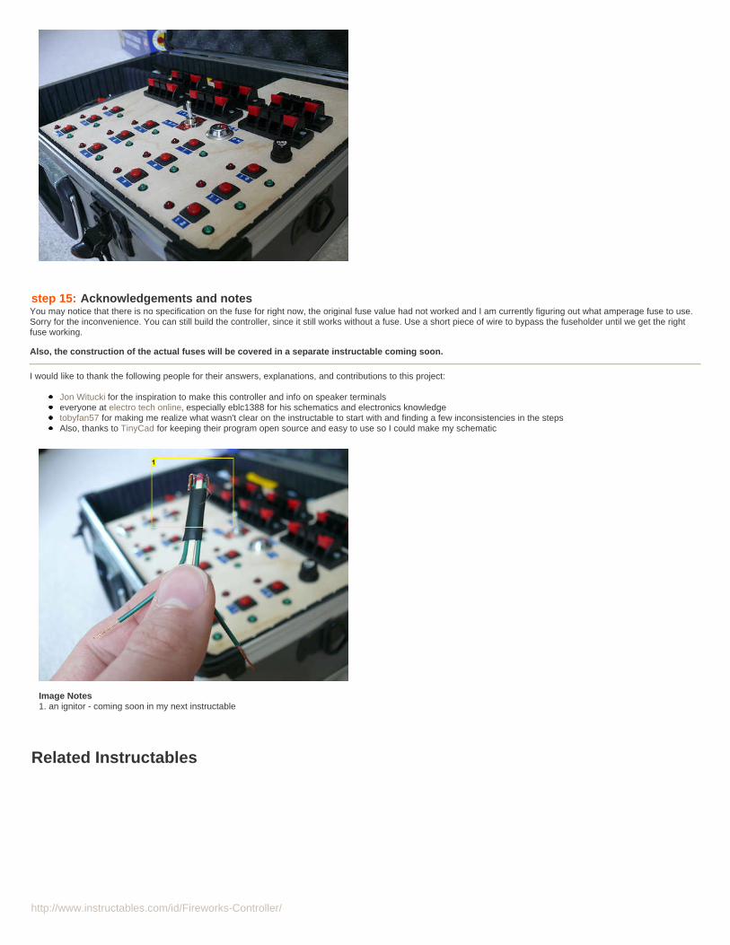
step 14: Finished board . . . . . . . . . . . . . . . . . . . . . . . . . . . . . . . . . . . . . . . . . . . . . . . . . . . . . . . . . . . . . . . . . . . . . . . . . . . . . . . . . . . . . . . . . . . . . . . . . . . . . . . . 17
step 15: Acknowledgements and notes . . . . . . . . . . . . . . . . . . . . . . . . . . . . . . . . . . . . . . . . . . . . . . . . . . . . . . . . . . . . . . . . . . . . . . . . . . . . . . . . . . . . . . . . . . . . 18
Related Instructables . . . . . . . . . . . . . . . . . . . . . . . . . . . . . . . . . . . . . . . . . . . . . . . . . . . . . . . . . . . . . . . . . . . . . . . . . . . . . . . . . . . . . . . . . . . . . . . . . . . . . . . . . . . 18
Advertisements . . . . . . . . . . . . . . . . . . . . . . . . . . . . . . . . . . . . . . . . . . . . . . . . . . . . . . . . . . . . . . . . . . . . . . . . . . . . . . . . . . . . . . . . . . . . . . . . . . . . . . . . . . . . . . . 19
Make Magazine Special Offer . . . . . . . . . . . . . . . . . . . . . . . . . . . . . . . . . . . . . . . . . . . . . . . . . . . . . . . . . . . . . . . . . . . . . . . . . . . . . . . . . . . . . . . . . . . . . . . . . . 19
Comments . . . . . . . . . . . . . . . . . . . . . . . . . . . . . . . . . . . . . . . . . . . . . . . . . . . . . . . . . . . . . . . . . . . . . . . . . . . . . . . . . . . . . . . . . . . . . . . . . . . . . . . . . . . . . . . . . . . 19
http://www.instructables.com/id/Fireworks-Controller/
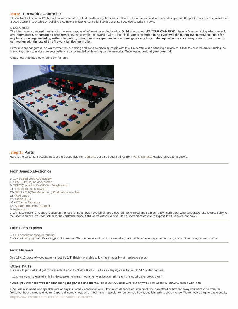
intro: Fireworks ControllerThis instructable is on a 12 channel fireworks controller that I built during the summer. It was a lot of fun to build, and is a blast (pardon the pun) to operate! I couldn't finda good quality instructable on building a complete fireworks controller like this one, so I decided to write my own.
DISCLAIMER:The information contained herein is for the sole purpose of information and education. Build this project AT YOUR OWN RISK. I have NO responsibility whatsoever forany injury, death, or damage to property of anyone operating or involved with using this fireworks controller. In no event will the author (Systemf92) be liable forany loss or damage including without limitation, indirect or consequential loss or damage, or any loss or damage whatsoever arising from the use of, or inconnection with the use of this firework ignition controller.
Fireworks are dangerous, so watch what you are doing and don't do anything stupid with this. Be careful when handling explosives. Clear the area before launching thefireworks, check to make sure your battery is disconnected while wiring up the fireworks. Once again, build at your own risk.
Okay, now that that's over, on to the fun part!
step 1: PartsHere is the parts list. I bought most of the electronics from Jameco, but also bought things from Parts Express, Radioshack, and Michaels.
From Jameco Electronics
1- 12v Sealed Lead Acid Battery1- SPST (Off-On) Keylock switch1- SPDT (3 position On-Off-On) Toggle switch24- LED mounting hardware12- SPST ( Off-(On) Momentary) Pushbutton switches12 - Red LEDs12- Green LEDs48 - 470 ohm Resistors12- Alligator clip pairs (24 total)2- battery clips1- 1/4" fuse (there is no specification on the fuse for right now, the original fuse value had not worked and I am currently figuring out what amperage fuse to use. Sorry forthe inconvenience. You can still build the controller, since it still works without a fuse. Use a short piece of wire to bypass the fuseholder for now.)
From Parts Express
6- Four conductor speaker terminalCheck out this page for different types of terminals. This controller's circuit is expandable, so it can have as many channels as you want it to have, so be creative!
From Michaels
One 12 x 12 piece of wood panel - must be 1/8" thick - available at Michaels, possibly at hardware stores
Other Parts> A case to put it all in -I got mine at a thrift shop for $5.00. It was used as a carrying case for an old VHS video camera.
> 12 short wood screws (that fit inside speaker terminal mounting holes but can still reach the wood panel below them)
> Also, you will need wire for connecting the panel components. I used 22AWG solid wire, but any wire from about 22-18AWG should work fine.
> You will also need long speaker wire or any insulated 2 conductor wire. How much depends on how much you can afford or how far away you want to be from thefireworks. Both Lowes and Home Depot sell some cheap wire in bulk and in spools. Wherever you buy it, buy it in bulk to save money. We're not looking for audio quality
http://www.instructables.com/id/Fireworks-Controller/
here. I used 18 gauge lamp wire, which I bought in a bulk spool and cut into smaller lengths.
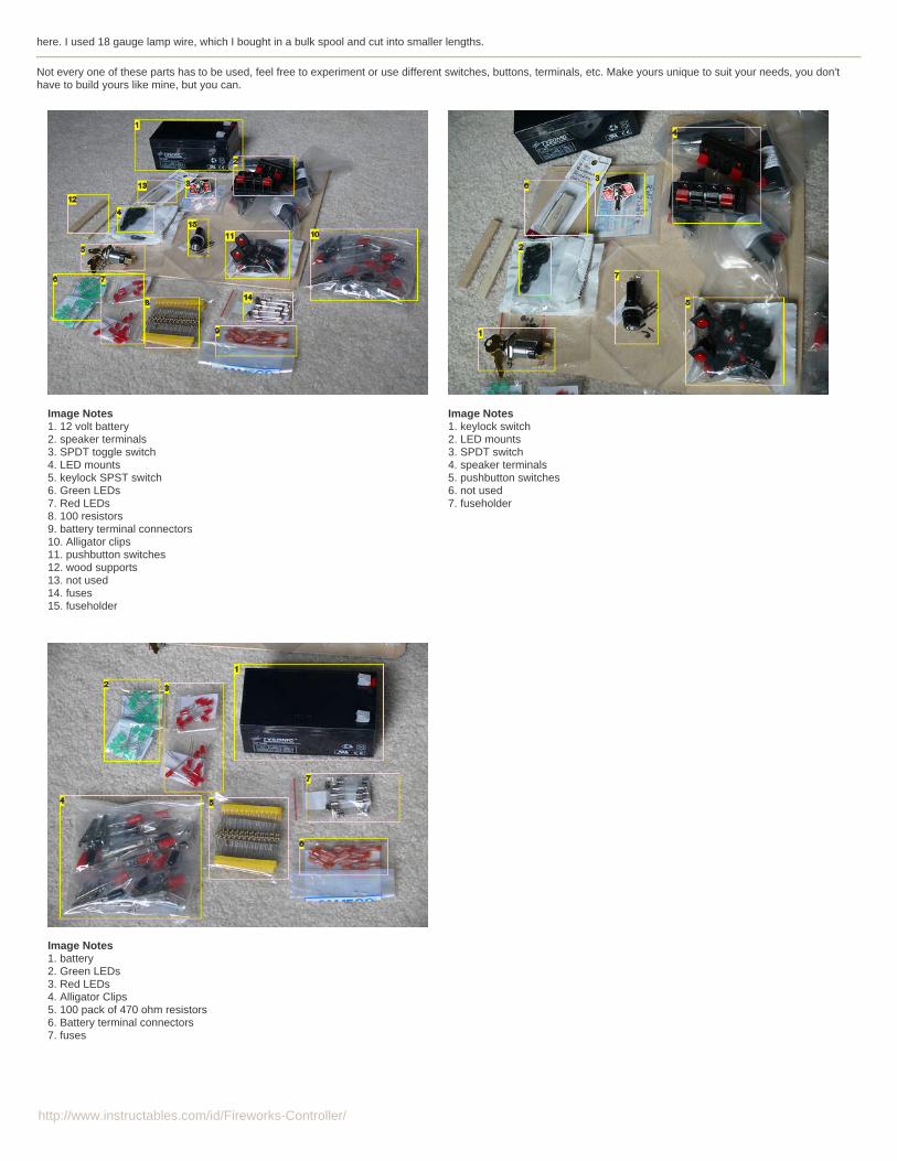
Not every one of these parts has to be used, feel free to experiment or use different switches, buttons, terminals, etc. Make yours unique to suit your needs, you don'thave to build yours like mine, but you can.
Image Notes1. 12 volt battery2. speaker terminals3. SPDT toggle switch4. LED mounts5. keylock SPST switch6. Green LEDs7. Red LEDs8. 100 resistors9. battery terminal connectors10. Alligator clips11. pushbutton switches12. wood supports13. not used14. fuses15. fuseholder
Image Notes1. keylock switch2. LED mounts3. SPDT switch4. speaker terminals5. pushbutton switches6. not used7. fuseholder
Image Notes1. battery2. Green LEDs3. Red LEDs4. Alligator Clips5. 100 pack of 470 ohm resistors6. Battery terminal connectors7. fuses
http://www.instructables.com/id/Fireworks-Controller/
step 2: Hardware neededWoodworking Tools
Drill (hand or power)Ratchet brace (or a bigger drill). I have one of these, so I used it. You don't have to use this.Auger bits (spiral shaped large drill bits)Drill bits - check with the place you bought your components from for hole diameters and dimensions.Dremel or other rotary toolDremel bits (sanding)A small saw (for cutting the plywood)C-clampsScrewdriverPencilRuler
Notes:A drill press would help to cut the holes in the panel, but I don't have one of those and you can still cut the holes with a regular drill.
If you don't have the right size drill bit for all of the panel-mounted parts you can use a dremel to widen the holes like I did.
Electronics ToolsSoldering ironRosin-core solderElectrical tapeNeedle nose pliersWire cuttersScissorsHelping hands (or build your own)
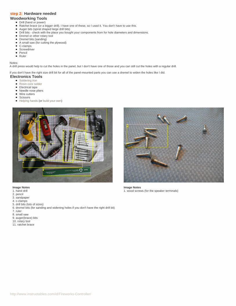
Image Notes1. hand drill2. pencil3. sandpaper4. c-clamps5. drill bits (lots of sizes)6. dremel bits (for sanding and widening holes if you don't have the right drill bit)7. ruler8. small saw9. auger(brace) bits10. rotary tool11. ratchet brace
Image Notes1. wood screws (for the speaker terminals)
http://www.instructables.com/id/Fireworks-Controller/
Image Notes1. scissors2. needle nose pliers3. wire cutters4. light duty rosin core solder5. electrical tape6. soldering iron7. assorted 22AWG wire8. something to keep the panel off of the table so it isn't resting on componentswhile soldering
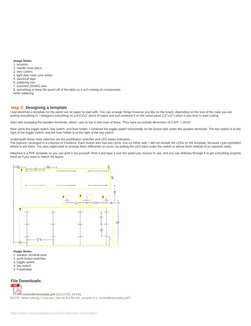
step 3: Designing a templateI just sketched a template for the panel out on paper to start with. You can arrange things however you like on the board, depending on the size of the case you areputting everything in. I designed everything on a 8.5"x11" piece of paper and just centered it on the wood panel (12"x12") when it was time to start cutting.
Start with arranging the speaker terminals, which I put on top in two rows of three. They have an outside dimension of 2-3/4" x 15/16".
Next came the toggle switch, key switch, and fuse holder. I centered the toggle switch horizontally on the board right under the speaker terminals. The key switch is to theright of the toggle switch, and the fuse holder is to the right of the key switch.
Underneath these main switches are the pushbutton switches and LED status indicators.The buttons I arranged in 4 columns of 3 buttons. Each button also has two LEDs; one on either side. I did not include the LEDs on the template, because I just eyeballedwhere to put them. You also might want to arrange them differently on yours, by putting the LED pairs under the switch or above them instead of on opposite sides.
Attached is a PDF template so you can print it out yourself. Print it and tape it over the panel you choose to use, and you can drill/saw through it to get everything properlylined up if you want to match my layout.
Image Notes1. speaker terminal slots2. push button switches3. toggle switch4. key switch5. Fuseholder
File Downloads
controllertemplate.pdf ((612x792) 48 KB)[NOTE: When saving, if you see .tmp as the file ext, rename it to 'controllertemplate.pdf']
http://www.instructables.com/id/Fireworks-Controller/
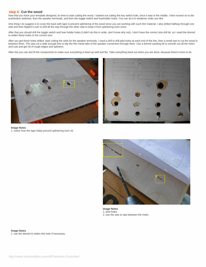
step 4: Cut the woodNow that you have your template designed, its time to start cutting the wood. I started out cutting the key switch hole, since it was in the middle. I then moved on to thepushbutton switches, then the speaker terminals, and then the toggle switch and fuseholder holes. You can do it in whatever order you like.
One thing I do suggest is to cover the back with tape to prevent splintering of the wood since you are working with such thin material. I also drilled halfway through oneside and then flipped it over to drill all the way through the other side to keep it from splintering even more.
After that you should drill the toggle switch and fuse holder holes (I didn't do this in order, don't know why not). I don't have the correct size drill bit, so I used the dremelto widen these holes to the correct size.
After you get those holes drilled, start cutting the slots for the speaker terminals. I used a drill to drill pilot holes at each end of the line, then a small saw to cut the wood inbetween them. The saw cut a wide enough line to slip the thin metal tabs of the speaker connectors through them. Use a dremel sanding bit to smooth out all the holesand cuts and get rid of rough edges and splinters.
After this you can test fit the components to make sure everything is lined up well and fits. Take everything back out when you are done, because there's more to do.
Image Notes1. notice how the tape helps prevent splintering (sort of)
Image Notes1. use the dremel to widen this hole if necessary.
Image Notes1. pilot holes2. use the saw to saw between the holes
http://www.instructables.com/id/Fireworks-Controller/
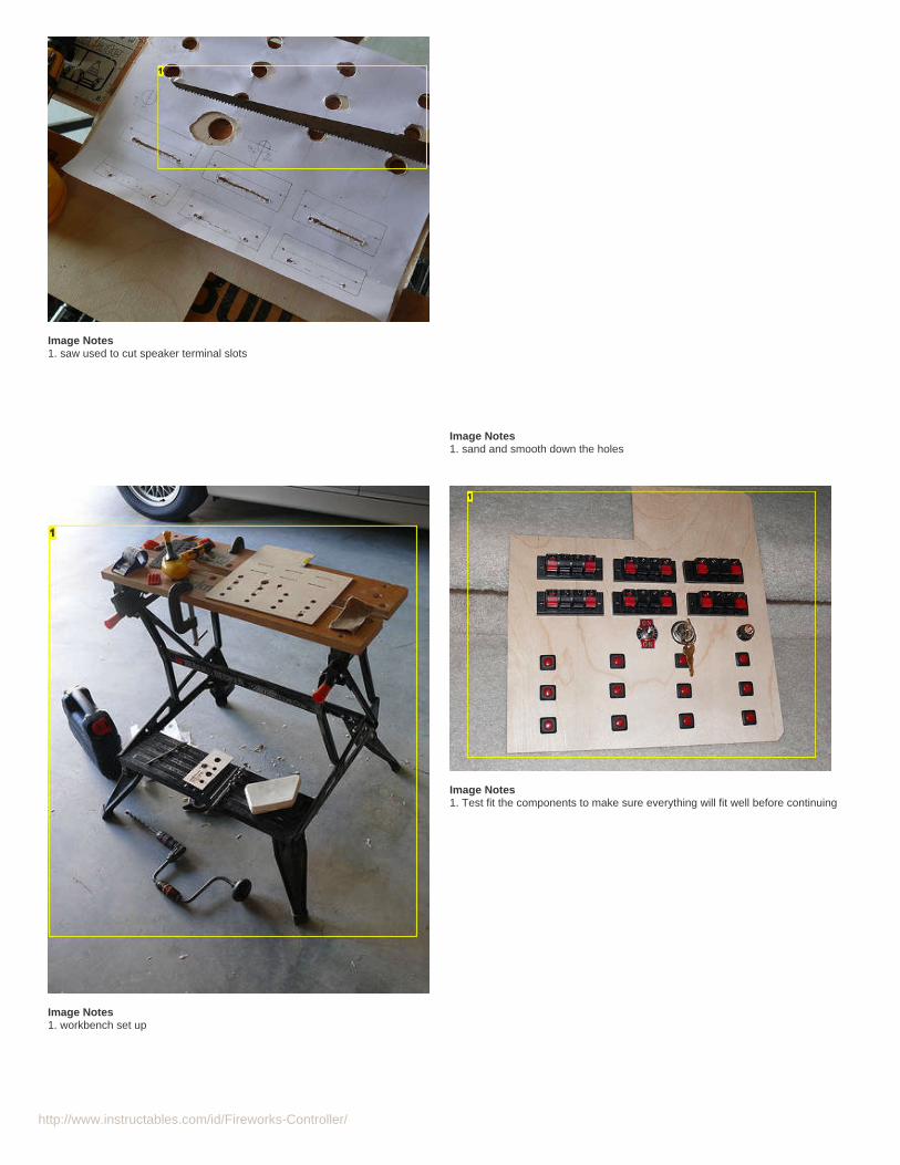
Image Notes1. saw used to cut speaker terminal slots
Image Notes1. sand and smooth down the holes
Image Notes1. workbench set up
Image Notes1. Test fit the components to make sure everything will fit well before continuing
http://www.instructables.com/id/Fireworks-Controller/
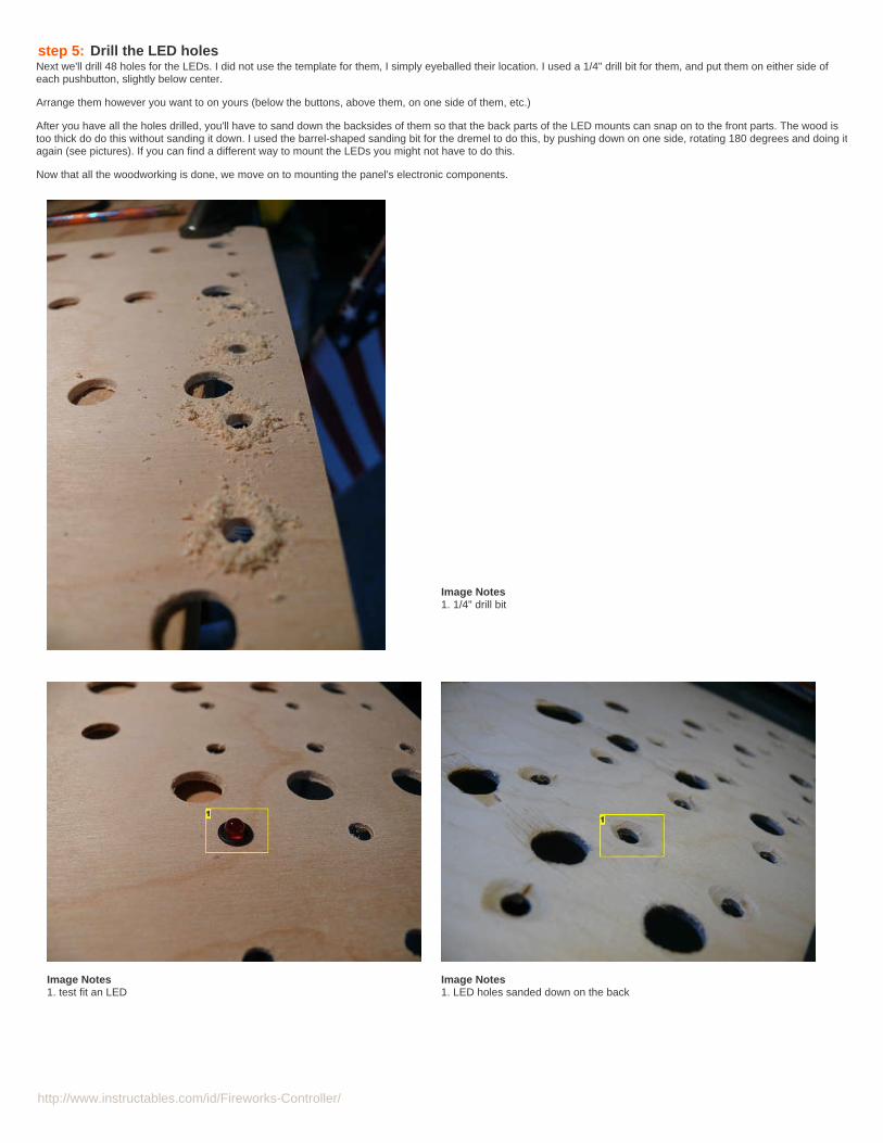
step 5: Drill the LED holesNext we'll drill 48 holes for the LEDs. I did not use the template for them, I simply eyeballed their location. I used a 1/4" drill bit for them, and put them on either side ofeach pushbutton, slightly below center.
Arrange them however you want to on yours (below the buttons, above them, on one side of them, etc.)
After you have all the holes drilled, you'll have to sand down the backsides of them so that the back parts of the LED mounts can snap on to the front parts. The wood istoo thick do do this without sanding it down. I used the barrel-shaped sanding bit for the dremel to do this, by pushing down on one side, rotating 180 degrees and doing itagain (see pictures). If you can find a different way to mount the LEDs you might not have to do this.
Now that all the woodworking is done, we move on to mounting the panel's electronic components.
Image Notes1. 1/4" drill bit
Image Notes1. test fit an LED
Image Notes1. LED holes sanded down on the back
http://www.instructables.com/id/Fireworks-Controller/
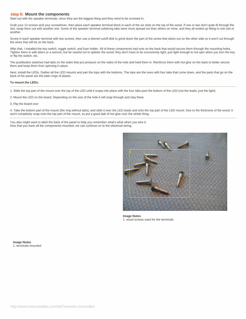
step 6: Mount the componentsStart out with the speaker terminals, since they are the biggest thing and they need to be screwed in.
Grab your 12 screws and your screwdriver, then place each speaker terminal block in each of the six slots on the top of the wood. If one or two don't quite fit through theslot, swap them out with another one. Some of the speaker terminal soldering tabs were more spread out than others on mine, and they all ended up fitting in one slot oranother.
Screw in each speaker terminal with two screws, then use a dremel cutoff disk to grind down the part of the screw that sticks out on the other side so it won't cut throughthe wires that will be on the back.
After that, I installed the key switch, toggle switch, and fuse holder. All of these components had nuts on the back that would secure them through the mounting holes.Tighten them in with pliers or a wrench, but be careful not to splinter the wood; they don't have to be excessively tight, just tight enough to not spin when you turn the keyor flip the switch, etc.
The pushbutton switches had tabs on the sides that put pressure on the sides of the hole and held them in. Reinforce them with hot glue on the back to better securethem and keep them from spinning in place.
Next, install the LEDs. Gather all the LED mounts and pair the tops with the bottoms. The tops are the ones with four tabs that come down, and the parts that go on theback of the panel are the plain rings of plastic.
To mount the LEDs:
1. Slide the top part of the mount over the top of the LED until it snaps into place with the four tabs past the bottom of the LED (not the leads, just the light)
2. Mount the LED on the board. Depending on the size of the hole it will snap through and stay there.
3. Flip the board over
4. Take the bottom part of the mount (the ring without tabs), and slide it over the LED leads and onto the top part of the LED mount. Due to the thickness of the wood, itwon't completely snap onto the top part of the mount, so put a good dab of hot glue over the whole thing.
You also might want to label the back of the panel to help you remember what's what when you wire it.Now that you have all the components mounted, we can continue on to the electrical wiring.
Image Notes1. terminals mounted
Image Notes1. wood screws used for the terminals
http://www.instructables.com/id/Fireworks-Controller/
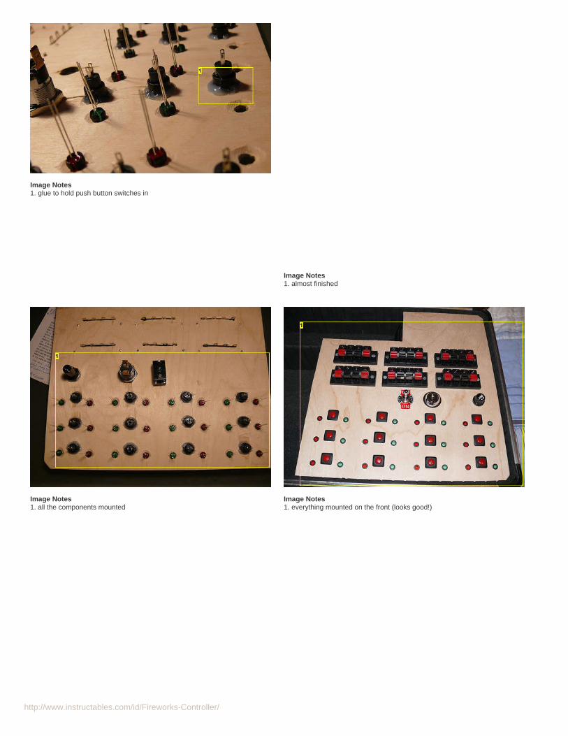
Image Notes1. glue to hold push button switches in
Image Notes1. almost finished
Image Notes1. all the components mounted
Image Notes1. everything mounted on the front (looks good!)
http://www.instructables.com/id/Fireworks-Controller/
Image Notes1. glue to hold in LEDs2. labels - very important when wiring
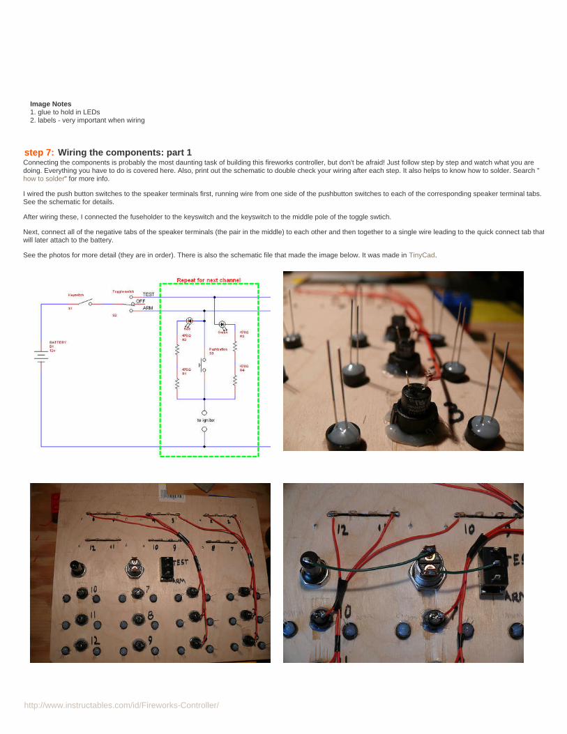
step 7: Wiring the components: part 1Connecting the components is probably the most daunting task of building this fireworks controller, but don't be afraid! Just follow step by step and watch what you aredoing. Everything you have to do is covered here. Also, print out the schematic to double check your wiring after each step. It also helps to know how to solder. Search "how to solder" for more info.
I wired the push button switches to the speaker terminals first, running wire from one side of the pushbutton switches to each of the corresponding speaker terminal tabs.See the schematic for details.
After wiring these, I connected the fuseholder to the keyswitch and the keyswitch to the middle pole of the toggle swtich.
Next, connect all of the negative tabs of the speaker terminals (the pair in the middle) to each other and then together to a single wire leading to the quick connect tab thatwill later attach to the battery.
See the photos for more detail (they are in order). There is also the schematic file that made the image below. It was made in TinyCad.
http://www.instructables.com/id/Fireworks-Controller/
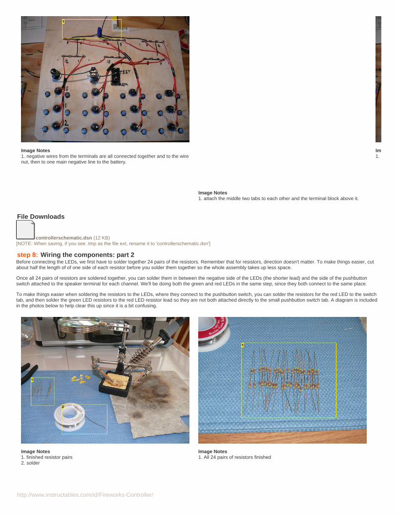
Image Notes1. negative wires from the terminals are all connected together and to the wirenut, then to one main negative line to the battery.
Image Notes1. attach the middle two tabs to each other and the terminal block above it.
Image Notes1. connect all the speaker terminal blocks to the wire nut
File Downloads
controllerschematic.dsn (12 KB)[NOTE: When saving, if you see .tmp as the file ext, rename it to 'controllerschematic.dsn']
step 8: Wiring the components: part 2Before connecting the LEDs, we first have to solder together 24 pairs of the resistors. Remember that for resistors, direction doesn't matter. To make things easier, cutabout half the length of of one side of each resistor before you solder them together so the whole assembly takes up less space.
Once all 24 pairs of resistors are soldered together, you can solder them in between the negative side of the LEDs (the shorter lead) and the side of the pushbuttonswitch attached to the speaker terminal for each channel. We'll be doing both the green and red LEDs in the same step, since they both connect to the same place.
To make things easier when soldering the resistors to the LEDs, where they connect to the pushbutton switch, you can solder the resistors for the red LED to the switchtab, and then solder the green LED resistors to the red LED resistor lead so they are not both attached directly to the small pushbutton switch tab. A diagram is includedin the photos below to help clear this up since it is a bit confusing.
Image Notes1. finished resistor pairs2. solder
Image Notes1. All 24 pairs of resistors finished
http://www.instructables.com/id/Fireworks-Controller/
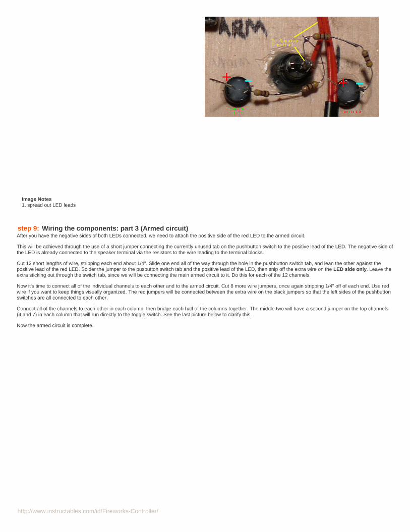
Image Notes1. spread out LED leads
step 9: Wiring the components: part 3 (Armed circuit)After you have the negative sides of both LEDs connected, we need to attach the positive side of the red LED to the armed circuit.
This will be achieved through the use of a short jumper connecting the currently unused tab on the pushbutton switch to the positive lead of the LED. The negative side ofthe LED is already connected to the speaker terminal via the resistors to the wire leading to the terminal blocks.
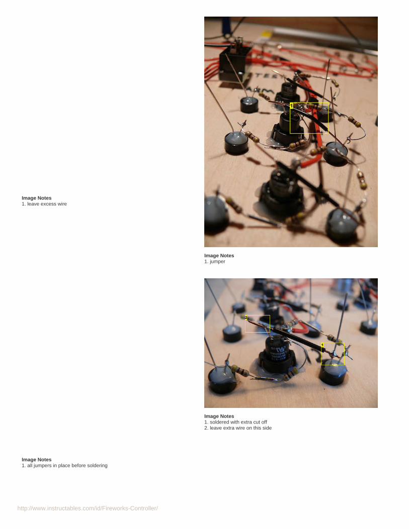
Cut 12 short lengths of wire, stripping each end about 1/4". Slide one end all of the way through the hole in the pushbutton switch tab, and lean the other against thepositive lead of the red LED. Solder the jumper to the pusbutton switch tab and the positive lead of the LED, then snip off the extra wire on the LED side only. Leave theextra sticking out through the switch tab, since we will be connecting the main armed circuit to it. Do this for each of the 12 channels.
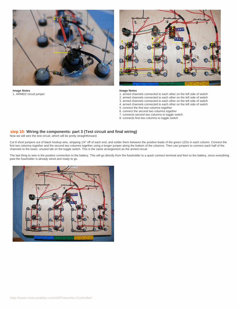
Now it's time to connect all of the individual channels to each other and to the armed circuit. Cut 8 more wire jumpers, once again stripping 1/4" off of each end. Use redwire if you want to keep things visually organized. The red jumpers will be connected between the extra wire on the black jumpers so that the left sides of the pushbuttonswitches are all connected to each other.
Connect all of the channels to each other in each column, then bridge each half of the columns together. The middle two will have a second jumper on the top channels(4 and 7) in each column that will run directly to the toggle switch. See the last picture below to clarify this.
Now the armed circuit is complete.
http://www.instructables.com/id/Fireworks-Controller/
Image Notes1. leave excess wire
Image Notes1. jumper
Image Notes1. all jumpers in place before soldering
Image Notes1. soldered with extra cut off2. leave extra wire on this side
http://www.instructables.com/id/Fireworks-Controller/
Image Notes1. ARMED circuit jumper
Image Notes1. armed channels connected to each other on the left side of switch2. armed channels connected to each other on the left side of switch3. armed channels connected to each other on the left side of switch4. armed channels connected to each other on the left side of switch5. connect the first two columns together6. connect the second two columns together7. connects second two columns to toggle switch8. connects first two columns to toggle switch
step 10: Wiring the components: part 3 (Test circuit and final wiring)Now we will wire the test circuit, which will be pretty straightforward.
Cut 8 short jumpers out of black hookup wire, stripping 1/4" off of each end, and solder them between the positive leads of the green LEDs in each column. Connect thefirst two columns together and the second two columns together using a longer jumper along the bottom of the columns. Then use jumpers to connect each half of thechannels to the lower, unused tab on the toggle switch. This is the same arrangement as the armed circuit.
The last thing to wire is the positive connection to the battery. This will go directly from the fuseholder to a quick connect terminal and then to the battery, since everythingpast the fuseholder is already wired and ready to go.
http://www.instructables.com/id/Fireworks-Controller/
step 11: Testing your wiringAfter you have everything finished, connected, and soldered, it is a good idea to test each channel to make sure everything is wired right and there are no shorts.
Install a fuse in the fuseholder and attach the negative lead (that goes directly to the speaker terminals) to the negative connection on the battery and the positive lead(that goes to the fuseholder) to the positive connection on the battery.
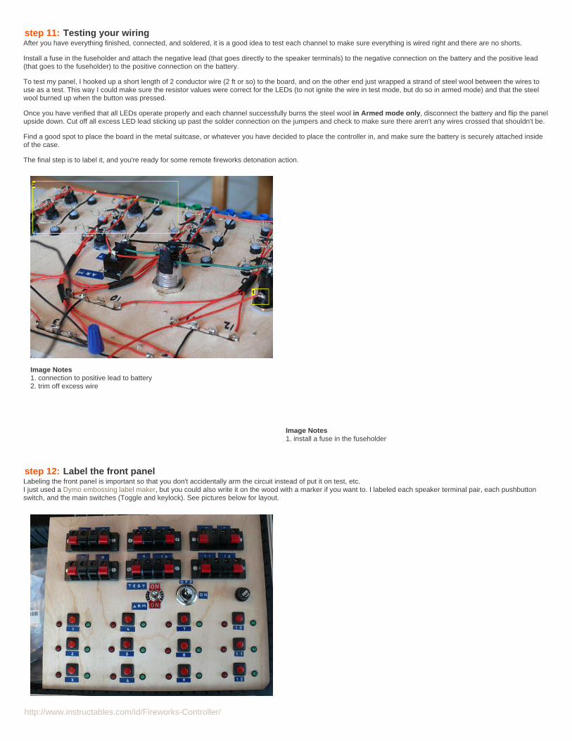
To test my panel, I hooked up a short length of 2 conductor wire (2 ft or so) to the board, and on the other end just wrapped a strand of steel wool between the wires touse as a test. This way I could make sure the resistor values were correct for the LEDs (to not ignite the wire in test mode, but do so in armed mode) and that the steelwool burned up when the button was pressed.
Once you have verified that all LEDs operate properly and each channel successfully burns the steel wool in Armed mode only, disconnect the battery and flip the panelupside down. Cut off all excess LED lead sticking up past the solder connection on the jumpers and check to make sure there aren't any wires crossed that shouldn't be.
Find a good spot to place the board in the metal suitcase, or whatever you have decided to place the controller in, and make sure the battery is securely attached insideof the case.
The final step is to label it, and you're ready for some remote fireworks detonation action.
Image Notes1. connection to positive lead to battery2. trim off excess wire
Image Notes1. install a fuse in the fuseholder
step 12: Label the front panelLabeling the front panel is important so that you don't accidentally arm the circuit instead of put it on test, etc.I just used a Dymo embossing label maker, but you could also write it on the wood with a marker if you want to. I labeled each speaker terminal pair, each pushbuttonswitch, and the main switches (Toggle and keylock). See pictures below for layout.
http://www.instructables.com/id/Fireworks-Controller/
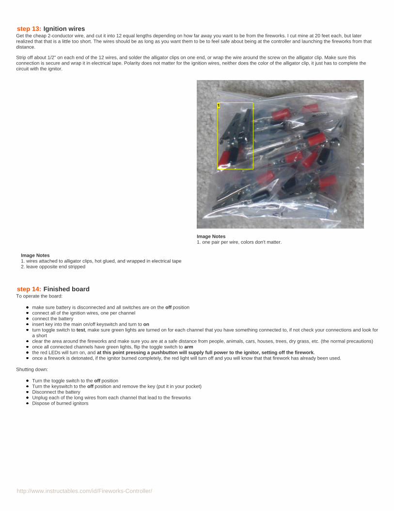
step 13: Ignition wiresGet the cheap 2-conductor wire, and cut it into 12 equal lengths depending on how far away you want to be from the fireworks. I cut mine at 20 feet each, but laterrealized that that is a little too short. The wires should be as long as you want them to be to feel safe about being at the controller and launching the fireworks from thatdistance.
Strip off about 1/2" on each end of the 12 wires, and solder the alligator clips on one end, or wrap the wire around the screw on the alligator clip. Make sure thisconnection is secure and wrap it in electrical tape. Polarity does not matter for the ignition wires, neither does the color of the alligator clip, it just has to complete thecircuit with the ignitor.
Image Notes1. wires attached to alligator clips, hot glued, and wrapped in electrical tape2. leave opposite end stripped
Image Notes1. one pair per wire, colors don't matter.
step 14: Finished boardTo operate the board:
make sure battery is disconnected and all switches are on the off positionconnect all of the ignition wires, one per channelconnect the batteryinsert key into the main on/off keyswitch and turn to onturn toggle switch to test, make sure green lights are turned on for each channel that you have something connected to, if not check your connections and look fora shortclear the area around the fireworks and make sure you are at a safe distance from people, animals, cars, houses, trees, dry grass, etc. (the normal precautions)once all connected channels have green lights, flip the toggle switch to armthe red LEDs will turn on, and at this point pressing a pushbutton will supply full power to the ignitor, setting off the firework.once a firework is detonated, if the ignitor burned completely, the red light will turn off and you will know that that firework has already been used.
Shutting down:
Turn the toggle switch to the off positionTurn the keyswitch to the off position and remove the key (put it in your pocket)Disconnect the batteryUnplug each of the long wires from each channel that lead to the fireworksDispose of burned ignitors
http://www.instructables.com/id/Fireworks-Controller/
step 15: Acknowledgements and notesYou may notice that there is no specification on the fuse for right now, the original fuse value had not worked and I am currently figuring out what amperage fuse to use.Sorry for the inconvenience. You can still build the controller, since it still works without a fuse. Use a short piece of wire to bypass the fuseholder until we get the rightfuse working.
Also, the construction of the actual fuses will be covered in a separate instructable coming soon.
I would like to thank the following people for their answers, explanations, and contributions to this project:
Jon Witucki for the inspiration to make this controller and info on speaker terminalseveryone at electro tech online, especially eblc1388 for his schematics and electronics knowledgetobyfan57 for making me realize what wasn't clear on the instructable to start with and finding a few inconsistencies in the stepsAlso, thanks to TinyCad for keeping their program open source and easy to use so I could make my schematic
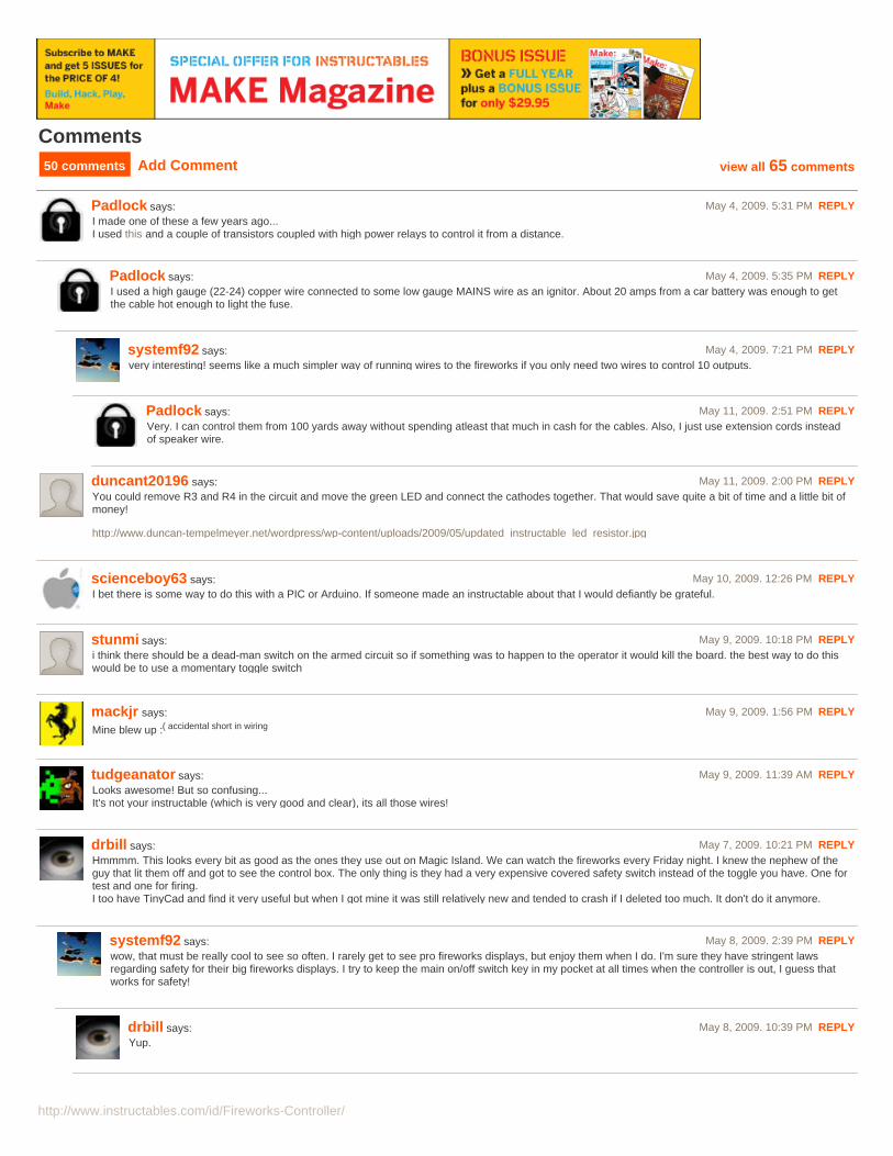
Image Notes1. an ignitor - coming soon in my next instructable
Related Instructables
http://www.instructables.com/id/Fireworks-Controller/
AdvertisementsMake Magazine Special Offer
Comments50 comments Add Comment view all 65 comments
Padlock says: May 4, 2009. 5:31 PM REPLYI made one of these a few years ago...I used this and a couple of transistors coupled with high power relays to control it from a distance.
Padlock says: May 4, 2009. 5:35 PM REPLYI used a high gauge (22-24) copper wire connected to some low gauge MAINS wire as an ignitor. About 20 amps from a car battery was enough to getthe cable hot enough to light the fuse.
systemf92 says: May 4, 2009. 7:21 PM REPLYvery interesting! seems like a much simpler way of running wires to the fireworks if you only need two wires to control 10 outputs.
Padlock says: May 11, 2009. 2:51 PM REPLYVery. I can control them from 100 yards away without spending atleast that much in cash for the cables. Also, I just use extension cords insteadof speaker wire.
duncant20196 says: May 11, 2009. 2:00 PM REPLYYou could remove R3 and R4 in the circuit and move the green LED and connect the cathodes together. That would save quite a bit of time and a little bit ofmoney!
http://www.duncan-tempelmeyer.net/wordpress/wp-content/uploads/2009/05/updated_instructable_led_resistor.jpg
scienceboy63 says: May 10, 2009. 12:26 PM REPLYI bet there is some way to do this with a PIC or Arduino. If someone made an instructable about that I would defiantly be grateful.
stunmi says: May 9, 2009. 10:18 PM REPLYi think there should be a dead-man switch on the armed circuit so if something was to happen to the operator it would kill the board. the best way to do thiswould be to use a momentary toggle switch
mackjr says: May 9, 2009. 1:56 PM REPLY
Mine blew up :( accidental short in wiring
tudgeanator says: May 9, 2009. 11:39 AM REPLYLooks awesome! But so confusing...It's not your instructable (which is very good and clear), its all those wires!
drbill says: May 7, 2009. 10:21 PM REPLYHmmmm. This looks every bit as good as the ones they use out on Magic Island. We can watch the fireworks every Friday night. I knew the nephew of theguy that lit them off and got to see the control box. The only thing is they had a very expensive covered safety switch instead of the toggle you have. One fortest and one for firing.I too have TinyCad and find it very useful but when I got mine it was still relatively new and tended to crash if I deleted too much. It don't do it anymore.
systemf92 says: May 8, 2009. 2:39 PM REPLYwow, that must be really cool to see so often. I rarely get to see pro fireworks displays, but enjoy them when I do. I'm sure they have stringent lawsregarding safety for their big fireworks displays. I try to keep the main on/off switch key in my pocket at all times when the controller is out, I guess thatworks for safety!
drbill says: May 8, 2009. 10:39 PM REPLYYup.

http://www.instructables.com/id/Fireworks-Controller/
vuurwerkbar says: May 8, 2009. 6:04 AM REPLYgood job, learned much from this project
systemf92 says: May 8, 2009. 2:40 PM REPLYThank you, I'm very glad you did. Let me know if you have any questions.
explosivemaker says: May 7, 2009. 12:14 PM REPLY...too bad you didn't have a drill press to do the drilling.....very nice though....
systemf92 says: May 7, 2009. 6:13 PM REPLYyeah, it definitely would have helped make it quicker and more precise, but hey I manage to make do with what I have. Thank you.
explosivemaker says: May 8, 2009. 11:19 AM REPLY....I don't have one (yet) either....you did much better with hand tools than I would have done...thumbs up....
moorea7 says: May 7, 2009. 11:52 AM REPLYYou can get 2 position key switches that would enable you to have your test and arm controls in the same switch, it would also give you the ability to lock itinto test mode!
systemf92 says: May 7, 2009. 4:58 PM REPLYTest and arm controls are already in the same switch, I don't understand. Are talking about On-Off-On 3 position keyswitches?
crapflinger says: May 5, 2009. 5:38 AM REPLYhttp://www.electronics123.com/s.nl;jsessionid=ac112b1f1f4325aeae241937460e9936dc68c8d7b1d6.e3eTaxiNaN0Te3iQaNmRbhmNay1ynknvrkLOlQzNp65In0?sc=8&category=35&it=A&id=291
i've got plans to make a computer controlled contraption that uses the above relay board (actually posted an ible a year or so ago about it)...the advantage is that you can have all the firing "gear"(i.e. power and all the connections for the fireworks themselves) in once location....then run a 100' (or more) serial cable back to your firing station and use a laptop to fire...
you can either automate it (so that you can press go and drink a beer and watch) or make your own program (or use the one that you get from the kit maker) to do it manually...
crapflinger says: May 5, 2009. 5:42 AM REPLYalso...i need to look it up...but someone here on ibles has posted info on using resistors as ignitors....passing 24v through the right sized resistor willcause it to ignite....they're ridiculously cheap and easy to wire up
systemf92 says: May 5, 2009. 2:14 PM REPLYyeah, I also saw that for the first time here on instructables after posting mine, I have to try this now...
systemf92 says: May 5, 2009. 2:18 PM REPLYand also, regarding those relay boards, those look good but are a little pricey. They would work nicely though. Let me know if you use one, I'd liketo see how it turns out.
crapflinger says: May 6, 2009. 5:58 AM REPLYwell...i bought a house this year so the gub'ment is giving me some money for stimulating the economy (neat!) so i plan on getting two ofthose kits and linking them (each has 8 relays so i'd be able to do 16 with it)...i plan on just making the controller setup modular(without thefireworks part)...that way i can use the controller any way i want once it's built.....probably going to use it as a computer controlled bar insteadof a fireworks controller...but honestly...once the controller part is set up and done....it's pretty much the same thing....you tell it to fire a relayand it sends whatever voltage you're pushing down the wire....so it should be able to turn on a pump, fire fireworks, turn on a dancing hulagirl...etc...
crapflinger says: May 5, 2009. 6:17 AM REPLYfound emhttp://www.instructables.com/id/build_a_safer_fireworks_launcher_with_an_old_co/ this one talks about using 1/4 watt 10 ohm resistors as ignitors ina 24v system
i'm really interested in playing with the resistor ignitors...
http://www.instructables.com/id/Fireworks-Controller/
Syko Pyro says: May 6, 2009. 5:54 AM REPLYYou might actully want to think about adding a diode either for each of the channels or right at the beginning of the circuit on the positive rail of the circuitclosest to the battery. You could also do this on a PCB which would make things neater. If your not sure what a PCB is google it. (Printed Circuit Board)
Mikey D says: May 5, 2009. 6:03 PM REPLYI built a model rocket launcher for the Cub Scouts (6 channel) using a similar method. Phone cable was plenty large enough to handle the amperage but Ihad to wire a 12 pole rotary switch into a parallel 6 pole config. I used a metal cashbox and drilled the top for all of the switches and led's.
I am curious as to why you didn't just use a 1k ohm risistor instead of 2 470's in series.
Great ible, very clear and good instructions.
Mikey
Holden_vy_s says: May 4, 2009. 2:36 PM REPLYVery nice work! Personally i would of used aluminium for the face plate to carry on the metallic theme from the case but thats just me.
systemf92 says: May 4, 2009. 7:09 PM REPLYthanks!yes, aluminum would give it a nice touch. for this controller I used what I could easily get. I'll keep that in mind for version 2.0, maybe chemically etch thelabels right onto the panel!
tobyfan57 says: May 5, 2009. 5:08 PM REPLYHmmm... If you can access a laser engraver it would be really easy to label. Or if you have thin enough metal or strong enough laser it can make aquick job of cutting all holes. But I realize it is not practical for most people.
tobyfan57 says: May 5, 2009. 12:57 PM REPLYHey everyone. Having trouble finding a case like I was?
Well today (5/5) http://www.1saleaday.com/ has a similar looking case for @15 bucks after shipping. This is a good deal if you can't get one at thrift store /garage sale because these retail around $100.
systemf92 says: May 5, 2009. 2:22 PM REPLYAwesome find! the next best thing to stumbling across one at a thrift store, not a bad price.
tobyfan57 says: May 5, 2009. 5:02 PM REPLYA thrift store would defiantly be cheaper, but I could not find such a case and it adds to the feel of the project.
bowmaster says: May 4, 2009. 3:31 PM REPLYAwesome!!!
systemf92 says: May 4, 2009. 7:15 PM REPLYthanks, glad you like it!
bowmaster says: May 5, 2009. 3:15 PM REPLYHow could you not?
pudi.dk says: May 5, 2009. 7:03 AM REPLYCan aluminium sheet be used instead of plywood? Or is it too conducting
systemf92 says: May 5, 2009. 2:20 PM REPLYAluminum sheet could be used, assuming it is thick enough to not bend a lot when the pushbuttons are pressed. Also, you would have to be careful withthe resistors since they aren't insulated and we count on them staying in the same position, so consider using heat shrink tubing or electrical tape to keepthem insulated in case they were to touch the aluminum panel and create connections where we don't want them to be made.
http://www.instructables.com/id/Fireworks-Controller/
Hawkeye9009 says: May 4, 2009. 8:57 PM REPLYWhat about telephone cable? Could run a couple of telephone cables and have 12 channels. Or is that wire not strong enough? I'm only 18, not good withelectricity yet.
systemf92 says: May 4, 2009. 9:12 PM REPLYhmm, standard telephone cable is 22 or 24 AWG I believe, you would have to see how much the wire's resistance would affect the amount of power thatcould get to the ignitor and light it. It would depend on how long the telephone cable is. 24AWG copper wire has 19.1 ft/ohm of resistance, so a 20ftlength would give you a little over 1 ohm of resistance through the wire. Since I haven't calculated the amperage required to ignite a fuse, I couldn't tellyou if this will work or not. Hopefully someone else will read this with greater electronics knowledge than mine and be able to better answer yourquestion. I got the resistance of 24AWG wire from this website.
rocketman221 says: May 4, 2009. 9:04 PM REPLYNo you would need 18 awg wire minimum 16 awg would be better.
systemf92 says: May 5, 2009. 2:15 PM REPLYokay, 18AWG is what I happened to use.
thatoneguydavid says: May 4, 2009. 5:39 PM REPLYthis is a great idea. and i have a suggestion.
Instead of running 12 separate pairs of wire from your controller to your display setup, use a printer cable or something similar. At the other end make a"break-out" box to split it back out to your individual fireworks. You can find some really long cables and you can plug one in to the next and as long as thecable resistance is low enough, your trigger should still work fine.
peace,
systemf92 says: May 4, 2009. 7:24 PM REPLYExcellent suggestion, I also realized that doing this would be much more practical after having to buy so much cable, 20ft x 12=240ft. This will definatelybe included in version 2.0 : )
microman171 says: May 4, 2009. 5:32 PM REPLYLots to read, so sorry if this has been said...
To figure out the fuse value the easy way, build a regular ignitor, and then put an ammeter (multimeter) in the circuit. Battery - - - (Meter) - - - Ignitor.Obviuosly you need to wire the return to negative, but the diagram shows to wire in series.
If the amps needed to make the nichrome (or steel wool) is say, 3 amps, you use a 3.5A fuse. Depends on what you can get.
I don't know why you would use a fuse here...? As long as your wiring and all parts are rated for higher amps (I reckon your wire is probably rated at about10A).
Worst that can happen is you get a fire at the wool end... That's what you want anyway =)
systemf92 says: May 4, 2009. 7:17 PM REPLYOkay, thank you, this is simpler than I had anticipated! As soon as I replace my broken multimeter I'll get to it.And, you're right. After building this I realized that there was no reason to have the fuse in the circuit considering it's only 12v and not too much power.Next time I won't complicate things. I had planned to just take it off of the parts list and instructions, but figured that that would confuse people when theysaw it in the pictures.
microman171 says: May 4, 2009. 5:32 PM REPLYOh, and this is a great instructable!
BOOJAN says: May 4, 2009. 3:08 PM REPLYI must admit that you have really nice looking push button switch :D
systemf92 says: May 4, 2009. 7:15 PM REPLYthank you,they are from jameco electronics, I found out that they look better in real life than they do on the product page haha.

http://www.instructables.com/id/Fireworks-Controller/
Rob K says: May 4, 2009. 2:54 PM REPLYI saw a nice version a wile a go that had a used 4017 counters and a 555 timers.
A push button to select pad then push fire button to do a count down till it fires.
A lot more complex then what you have here and you have one that is fairly simple and easy to follow.
view all 65 comments