Embed Size (px)
Citation preview

Installation Instructions
Firewood boiler S3 Turbo
Translation of the original German installation instructions for techniciansRead and follow the instructions and safety information!
Technical changes, typographical errors and omissions reserved!M1081217_en | Edition 23/03/2017
Froeling GesmbH | A-4710 Grieskirchen, Industriestraße 12 | www.froeling.at
Table of Contents
1 General 41.1 About this manual 4
2 Safety 52.1 Hazard levels of warnings 52.2 Qualification of assembly staff 62.3 Personal protective equipment for assembly staff 62.4 Design Information 72.4.1 Notes on standards 7 General standards for heating systems 7 Standards for structural and safety devices 7 Standards for heating water 7 Regulations and standards for permitted fuels 82.4.2 Installation and approval of the heating system 82.4.3 General information for installation room (boiler room) 82.4.4 Requirements for central heating water 92.4.5 Notes for using pressure maintenance systems 112.4.6 Return lift 112.4.7 Combination with storage tank 122.4.8 Chimney connection/chimney system 14 Draught limiter 14 Measuring port 14 Boiler data for planning the flue gas system 15
3 Technology 163.1 Dimensions 163.2 Components and connections 173.3 Technical specifications 18
4 Assembly 234.1 Materials supplied 234.1.1 Tools required 234.2 Positioning 244.2.1 Temporary storage 244.3 Setting up in the boiler room 254.3.1 Remove boiler from pallet 254.3.2 Moving the boiler in the boiler room 254.3.3 Minimum distances in the boiler room 264.4 Before Installation 264.4.1 Changing door stops (as needed) 26 Converting the fuel loading door 284.4.2 Fitting the door handles 294.4.3 Setting and checking the seal on the doors 29 Positioning the doors 31
4.5 Installing the boiler 324.5.1 Assembly overview 32 Insulation 32 Air duct system 34
Table of Contents
2 Froeling GesmbH | A-4710 Grieskirchen, Industriestraße 12 | www.froeling.at
WOS system S3 Turbo 20-30 35 WOS system S3 Turbo 40-45 364.5.2 Fit flue gas pipe nozzle and the induced draught fan 374.5.3 Installing the pneumatic rods for the primary and secondary air 374.5.4 Final steps before insulating 394.5.5 Installing the insulation 394.5.6 Installing the door switch 424.5.7 Installing the back panel 424.5.8 Aligning the insulation and attaching the controller 434.5.9 Installing the cleaning port door and blank cover 454.5.10 Installing the insulated door 454.5.11 Fitting the sensors 484.5.12 Install the broadband probe (only with S-Tronic Lambda) 484.5.13 Installing the WOS system 494.5.14 Installing the manual controller/servo-motors 50 Mount the manual controller (with S-Tronic Plus control) 50 Mounting the servo-motors (with S-Tronic Lambda control) 50 Fit the cover plate. 51
4.6 Power connection and wiring 524.6.1 S-Tronic Plus / S-Tronic Lambda control 52 Power connection 52 Hydraulic system 534.6.2 Information on circulating pumps 54 Connecting a high efficiency pump 54 Connecting a squirrel cage standard pump 554.6.3 Concluding work 564.7 Connecting the hydraulic safety devices 57
5 Start-up 585.1 Before commissioning / configuring the boiler 585.2 Initial startup 595.2.1 Permitted fuels 59 Firewood 595.2.2 Fuels permitted under certain conditions 60 Wood briquettes 605.2.3 Non-permitted fuels 605.2.4 Heating up for the first time 61 Boiler with Lambda control 61 Boiler with manual controller 62
6 Decommissioning 656.1 Mothballing 656.2 Disassembly 656.3 Disposal 65
7 Appendix 667.1 Pressure equipment regulation 667.2 Addresses 677.2.1 Address of manufacturer 677.2.2 Address of the installer 67
Table of Contents
Installation Instructions S3 Turbo | M1081217_en 3
1 GeneralThank you for choosing a quality product from Froling. The product features a state-of-the-art design and conforms to all currently applicable standards and testingguidelines.Please read and observe the documentation provided and always keep it close to thesystem for reference. Observing the requirements and safety information in thedocumentation makes a significant contribution to safe, appropriate, environmentallyfriendly and economical operation of the system.The constant further development of our products means that there may be minordifferences from the pictures and content. If you discover any errors, please let usknow: [email protected] to technical change. The EC Declaration of Conformity is only valid in conjunction with a delivery certificate,which has been filled in correctly and signed as part of the commissioning process.The original document remains at the installation site. Commissioning installers orheating engineers are requested to return a copy of the delivery certificate togetherwith the guarantee card to Froling. On commissioning by FROLING Customer Servicethe validity of the delivery certificate will be noted on the customer service record.
1.1 About this manualThese installation instructions contain information for the following S3 boilers:S3 Turbo 181), S3 Turbo 20, S3 Turbo 30 (31 kW)2),S3 Turbo 40, S3 Turbo 45
1) S3 Turbo 18 only available in Italy; 2) S3 Turbo 30 with 31 kW nominal output only available in Austria and Italy;
Issuing a deliverycertificate
1 GeneralAbout this manual
4 Froeling GesmbH | A-4710 Grieskirchen, Industriestraße 12 | www.froeling.at
2 Safety
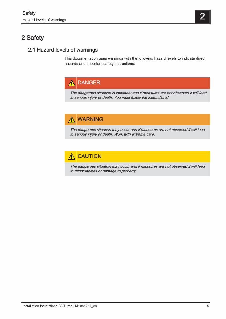
2.1 Hazard levels of warningsThis documentation uses warnings with the following hazard levels to indicate directhazards and important safety instructions:
DANGER
The dangerous situation is imminent and if measures are not observed it will leadto serious injury or death. You must follow the instructions!
WARNING
The dangerous situation may occur and if measures are not observed it will leadto serious injury or death. Work with extreme care.
CAUTION
The dangerous situation may occur and if measures are not observed it will leadto minor injuries or damage to property.
Safety 2Hazard levels of warnings
Installation Instructions S3 Turbo | M1081217_en 5
2.2 Qualification of assembly staff
CAUTION
Assembly and installation by unqualified persons:
Risk of personal injury and damage to property
During assembly and installation:❒ Observe the instructions and information in the manuals❒ Only allow appropriately qualified personnel to work on the system
Assembly, installation, initial startup and servicing must always be carried out byqualified personnel:- Heating technician / building technician- Electrical installation technician- Froling customer servicesThe assembly staff must have read and understood the instructions in thedocumentation.
2.3 Personal protective equipment for assembly staffYou must ensure that staff have the protective equipment specified by accidentprevention regulations.
▪ For transportation, setup and assembly:- suitable work wear- protective gloves- sturdy shoes (min. protection class S1P)
2 SafetyQualification of assembly staff
6 Froeling GesmbH | A-4710 Grieskirchen, Industriestraße 12 | www.froeling.at
2.4 Design Information
2.4.1 Notes on standardsThe system must be installed and commissioned in accordance with the local fire andbuilding regulations. Unless contrary to other national regulations, the latest versionsof the following standards and guidelines apply:
General standards for heating systems
EN 303-5 Boilers for solid fuels, manually and automatically fedcombustion systems, nominal heat output up to 500 kW
EN 12828 Heating systems in buildings - design of water-based heatingsystems
EN 13384-1 Chimneys - Thermal and fluid dynamic calculation methodsPart 1: Chimneys serving one appliance
ÖNORM H 5151 Planning of central hot water heating systems with or without hotwater preparation
ÖNORM M 7510-1 Guidelines for checking central heating systemsPart 1: General requirements and one-off inspections
ÖNORM M 7510-4 Guidelines for checking central heating systemsPart 4: Simple check for heating plants for solid fuels
Standards for structural and safety devices
ÖNORM H 5170 Heating installation - Requirements for construction and safetyengineering, as well as fire prevention and environmentalprotection
Standards for heating water
ÖNORM H 5195-1 Prevention of damage by corrosion and scale formation inclosed warm water heating systems at operating temperaturesup to 100°C (Austria).
VDI 2035 Prevention of damage hot water heating systems (Germany)
SWKI BT 102-01 Water quality for heating, steam, cooling and air conditioningsystems (Switzerland)
UNI 8065 Technical standard regulating hot water preparation.DM 26.06.2015 (Ministerial Decree specifying the minimumrequirements)Follow the instructions of this standard and any related updates.
Safety 2Design Information
Installation Instructions S3 Turbo | M1081217_en 7
Regulations and standards for permitted fuels
1. BImSchV First Order of the German Federal Government for theimplementation of the Federal Law on Emission Protection(Ordinance on Small and Medium Combustion Plants) in theversion published on 26 January 2010, BGBl. JG 2010 Part I No. 4.
EN ISO 17225-3 Solid bio-fuel - Fuel specifications and classesPart 3: Wood briquettes for non-industrial use
EN ISO 17225-5 Solid bio-fuel - Fuel specifications and classesPart 5: Firewood for non-industrial use
2.4.2 Installation and approval of the heating systemThe boiler should be operated in a closed heating system. The following standardsgovern the installation:
EN 12828 - Heating Systems in Buildings
NOTICE! Each heating system must be officially approved.The appropriate supervisory authority (inspection agency) must always be informedwhen installing or modifying a heating system, and authorisation must be obtainedfrom the building authorities:Austria: report to the construction authorities of the community or magistrateGermany: report new installations to an approved chimney sweep / the buildingauthorities.
2.4.3 General information for installation room (boiler room)
Boiler room characteristics▪ The floor must be even, clean and dry and have an adequate load-bearing
capacity.▪ There must not be a potentially explosive atmosphere in the boiler room as the
boiler is not suitable for use in potentially explosive environments.▪ The boiler room must be frost-free.▪ The boiler does not provide any light, so the customer must ensure sufficient
lighting in the boiler room in accordance with national workplace designregulations.
▪ When using the boiler above 2000 metres above sea level you should consult themanufacturer.
▪ Danger of fire due to flammable materials. The floor of the boiler room must not be flammable. No flammable materialsshould be stored near the boiler. Flammable objects (e.g. clothing) must not be puton the boiler to dry.
Note on standards
2 SafetyDesign Information
8 Froeling GesmbH | A-4710 Grieskirchen, Industriestraße 12 | www.froeling.at
▪ Damage due to impurities in combustion air.Do not use any solvents or cleaning agents containing chlorine and hydrogenhalides in the room where the boiler is installed (e.g. chlorination units forswimming pools).
▪ Keep the air suction opening of the boiler free of dust.▪ The system must be protected against the chewing or nesting of animals (e.g.
rodents etc.).
Ventilation of the boiler roomVentilation air for the boiler room should be taken from and expelled directly outside,and the openings and air ducts should be designed to prevent weather conditions(foliage, snowdrifts, etc.) from obstructing the air flow. Unless otherwise specified in the applicable building regulations for the boiler room,the following standards apply to the design and dimensions of the air ducts:
ÖNORM H 5170 - Construction and fire protection requirements
2.4.4 Requirements for central heating waterUnless contrary to other national regulations, the latest versions of the followingstandards and guidelines apply:
Austria:Germany:
ÖNORM H 5195VDI 2035
Switzerland:Italy:
SWKI BT 102-01UNI 8065
Observe the standards and also follow the recommendations below:❒ Aim for a pH value of between 8.2 and 10.0. If the central heating water comes
into contact with aluminium, the pH value must be between 8.0 and 8.5❒ Use prepared water which complies with the standards cited above for filling and
makeup water❒ Avoid leaks and use a closed heating system to maintain water quality during
operation❒ When filling with make-up water, always bleed the filling hose before connecting,
in order to prevent air from entering the system Advantages of prepared water:▪ Complies with the applicable standards▪ Less of a drop in output due to reduced limescale build-up▪ Less corrosion due to fewer aggressive substances▪ Long-term cost savings thanks to improved energy efficiency
Limit values for filling and make-up water:
Austria Germany Switzerland
Total hardness ≤ 1.0 mmol/L ≤ 2.0 mmol/L < 0.1 mmol/L
Conductivity - < 100µS/cm < 100 µS/cm
Note on standards
Safety 2Design Information
Installation Instructions S3 Turbo | M1081217_en 9
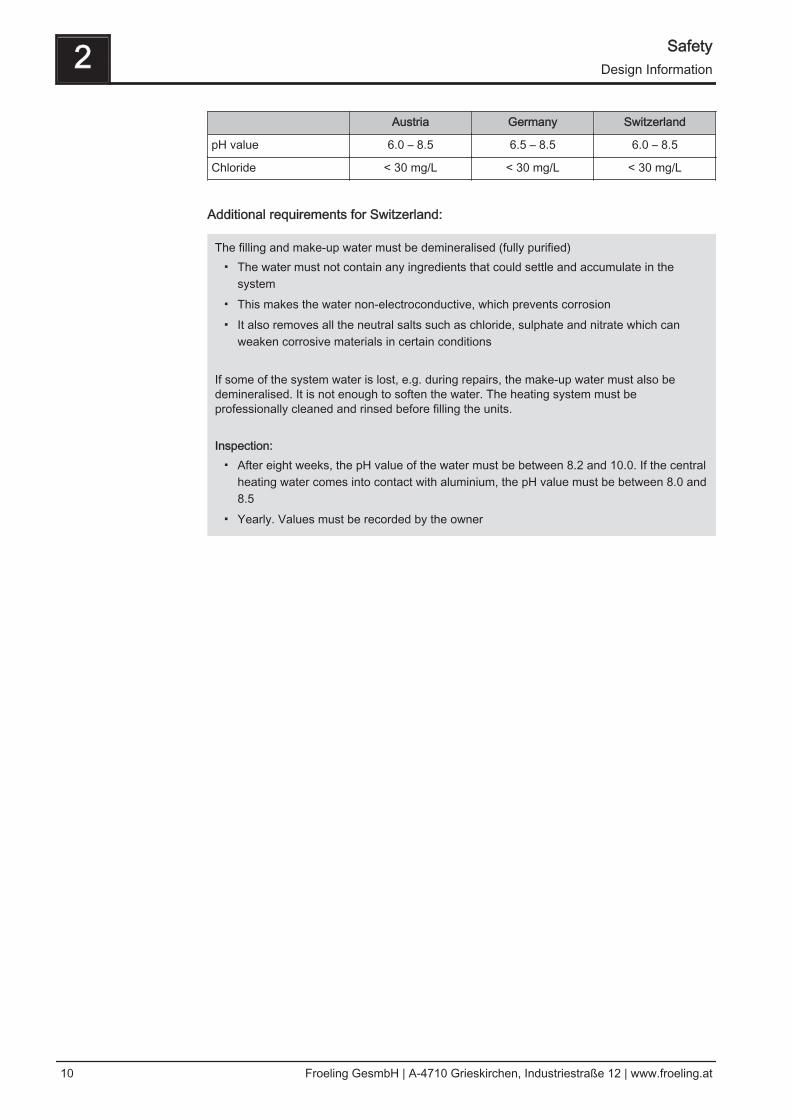
Austria Germany Switzerland
pH value 6.0 – 8.5 6.5 – 8.5 6.0 – 8.5
Chloride < 30 mg/L < 30 mg/L < 30 mg/L
Additional requirements for Switzerland:
The filling and make-up water must be demineralised (fully purified)▪ The water must not contain any ingredients that could settle and accumulate in the
system▪ This makes the water non-electroconductive, which prevents corrosion▪ It also removes all the neutral salts such as chloride, sulphate and nitrate which can
weaken corrosive materials in certain conditions If some of the system water is lost, e.g. during repairs, the make-up water must also bedemineralised. It is not enough to soften the water. The heating system must beprofessionally cleaned and rinsed before filling the units. Inspection:
▪ After eight weeks, the pH value of the water must be between 8.2 and 10.0. If the centralheating water comes into contact with aluminium, the pH value must be between 8.0 and8.5
▪ Yearly. Values must be recorded by the owner
2 SafetyDesign Information
10 Froeling GesmbH | A-4710 Grieskirchen, Industriestraße 12 | www.froeling.at
2.4.5 Notes for using pressure maintenance systemsPressure maintenance systems in hot-water heating systems keep the requiredpressure within predefined limits and balance out volume variations caused bychanges in the hot-water temperature. Two main systems are used:
Compressor-controlled pressure maintenance
In compressor-controlled pressure maintenance units, a variable air cushion in theexpansion tank is responsible for volume compensation and pressure maintenance. Ifthe pressure is too low, the compressor pumps air into the tank. If the pressure is toohigh, air is released by means of a solenoid valve. The systems are built solely withclosed-diaphragm expansion tanks to prevent the damaging introduction of oxygeninto the heating water.
Pump-controlled pressure maintenance
A pump-controlled pressure maintenance unit essentially consists of a pressure-maintenance pump, relief valve and an unpressurised receiving tank. The valvereleases hot water into the receiving tank if the pressure is too high. If the pressuredrops below a preset value, the pump draws water from the receiving tank and feeds itback into the heating system. Pump-controlled pressure maintenance systems withopen expansion tanks (e.g. without a diaphragm) introduce ambient oxygen via thesurface of the water, exposing the connected system components to the risk ofcorrosion. These systems offer no oxygen removal for the purposes of corrosioncontrol as required by VDI 2035 and in the interests of corrosion protection should notbe used.
2.4.6 Return liftIf the hot water return is below the minimum return temperature, some of the hot wateroutfeed will be mixed in.
CAUTION
Risk of dropping below dew point/condensation formation if operated withoutreturn temperature control.
Condensation water forms an aggressive condensate when combined withcombustion residue, leading to damage to the boiler.
Take the following precautions:❒ Regulations stipulate the use of a return temperature control.
➥ The minimum return temperature is 60 °C. We recommend fitting somesort of control device (e.g. thermometer).
Safety 2Design Information
Installation Instructions S3 Turbo | M1081217_en 11
2.4.7 Combination with storage tankObserve the regional regulations for using a storage tank!Certain subsidy guidelines prescribe compulsory requirements for the installation ofstorage tanks. Up-to-date information about individual subsidy guidelines can be foundat www.froeling.com. Channelling the heat generated by the Firewood boiler to a storage tank can bringmajor advantages, including:❒ better utilisation of fuel❒ more user-friendly operation in terms of reloading intervals❒ maximum independence from instantaneous heating requirements❒ minimal dirt in boiler and flue gas system
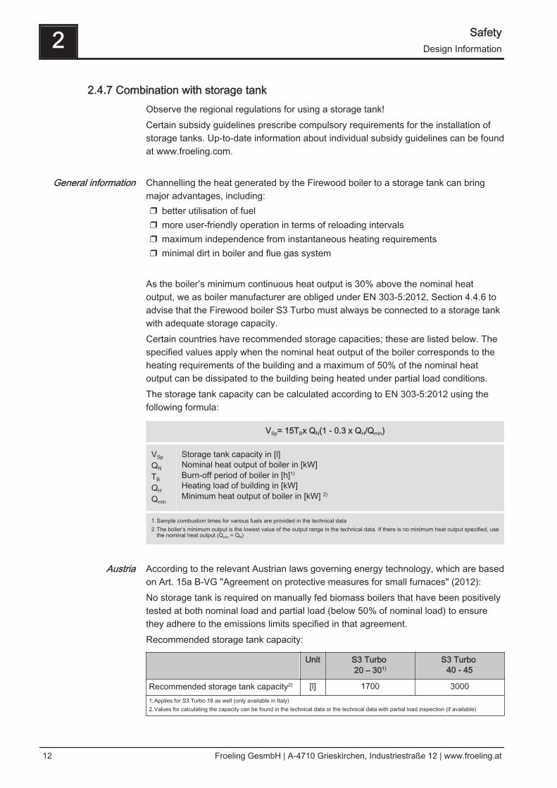
As the boiler’s minimum continuous heat output is 30% above the nominal heatoutput, we as boiler manufacturer are obliged under EN 303-5:2012, Section 4.4.6 toadvise that the Firewood boiler S3 Turbo must always be connected to a storage tankwith adequate storage capacity.Certain countries have recommended storage capacities; these are listed below. Thespecified values apply when the nominal heat output of the boiler corresponds to theheating requirements of the building and a maximum of 50% of the nominal heatoutput can be dissipated to the building being heated under partial load conditions.The storage tank capacity can be calculated according to EN 303-5:2012 using thefollowing formula:
VSp= 15TBx QN(1 - 0.3 x QH/Qmin)
VSp
QN
TB
QH
Qmin
Storage tank capacity in [l]Nominal heat output of boiler in [kW]Burn-off period of boiler in [h]1)
Heating load of building in [kW]Minimum heat output of boiler in [kW] 2)
1.Sample combustion times for various fuels are provided in the technical data2.The boiler’s minimum output is the lowest value of the output range in the technical data. If there is no minimum heat output specified, use
the nominal heat output (Qmin = QN)
According to the relevant Austrian laws governing energy technology, which are basedon Art. 15a B-VG "Agreement on protective measures for small furnaces" (2012):No storage tank is required on manually fed biomass boilers that have been positivelytested at both nominal load and partial load (below 50% of nominal load) to ensurethey adhere to the emissions limits specified in that agreement.Recommended storage tank capacity:
Unit S3 Turbo 20 – 301)
S3 Turbo 40 - 45
Recommended storage tank capacity2) [l] 1700 30001.Applies for S3 Turbo 18 as well (only available in Italy)2.Values for calculating the capacity can be found in the technical data or the technical data with partial load inspection (if available)
General information
Austria
2 SafetyDesign Information
12 Froeling GesmbH | A-4710 Grieskirchen, Industriestraße 12 | www.froeling.at
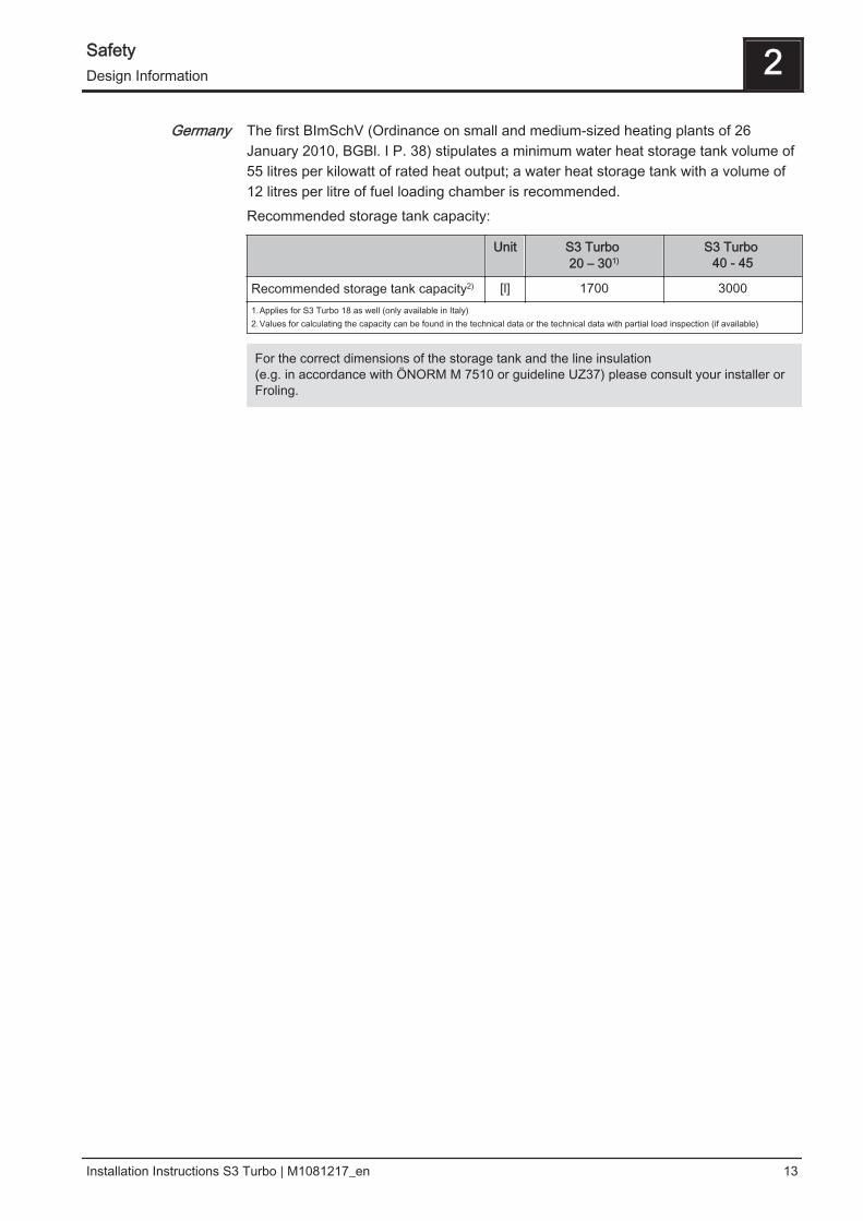
The first BImSchV (Ordinance on small and medium-sized heating plants of 26January 2010, BGBl. I P. 38) stipulates a minimum water heat storage tank volume of55 litres per kilowatt of rated heat output; a water heat storage tank with a volume of12 litres per litre of fuel loading chamber is recommended.Recommended storage tank capacity:
Unit S3 Turbo 20 – 301)
S3 Turbo 40 - 45
Recommended storage tank capacity2) [l] 1700 30001.Applies for S3 Turbo 18 as well (only available in Italy)2.Values for calculating the capacity can be found in the technical data or the technical data with partial load inspection (if available)
For the correct dimensions of the storage tank and the line insulation (e.g. in accordance with ÖNORM M 7510 or guideline UZ37) please consult your installer orFroling.
Germany
Safety 2Design Information
Installation Instructions S3 Turbo | M1081217_en 13
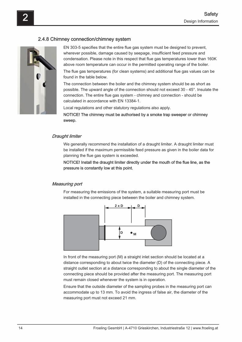
2.4.8 Chimney connection/chimney systemEN 303-5 specifies that the entire flue gas system must be designed to prevent,wherever possible, damage caused by seepage, insufficient feed pressure andcondensation. Please note in this respect that flue gas temperatures lower than 160Kabove room temperature can occur in the permitted operating range of the boiler.The flue gas temperatures (for clean systems) and additional flue gas values can befound in the table below.The connection between the boiler and the chimney system should be as short aspossible. The upward angle of the connection should not exceed 30 - 45°. Insulate theconnection. The entire flue gas system - chimney and connection - should becalculated in accordance with EN 13384-1.Local regulations and other statutory regulations also apply.NOTICE! The chimney must be authorised by a smoke trap sweeper or chimneysweep.
Draught limiterWe generally recommend the installation of a draught limiter. A draught limiter mustbe installed if the maximum permissible feed pressure as given in the boiler data forplanning the flue gas system is exceeded.NOTICE! Install the draught limiter directly under the mouth of the flue line, as thepressure is constantly low at this point.
Measuring portFor measuring the emissions of the system, a suitable measuring port must beinstalled in the connecting piece between the boiler and chimney system.
D
D
M
2 x D
In front of the measuring port (M) a straight inlet section should be located at adistance corresponding to about twice the diameter (D) of the connecting piece. Astraight outlet section at a distance corresponding to about the single diameter of theconnecting piece should be provided after the measuring port. The measuring portmust remain closed whenever the system is in operation.Ensure that the outside diameter of the sampling probes in the measuring port canaccommodate up to 13 mm. To avoid the ingress of false air, the diameter of themeasuring port must not exceed 21 mm.
2 SafetyDesign Information
14 Froeling GesmbH | A-4710 Grieskirchen, Industriestraße 12 | www.froeling.at
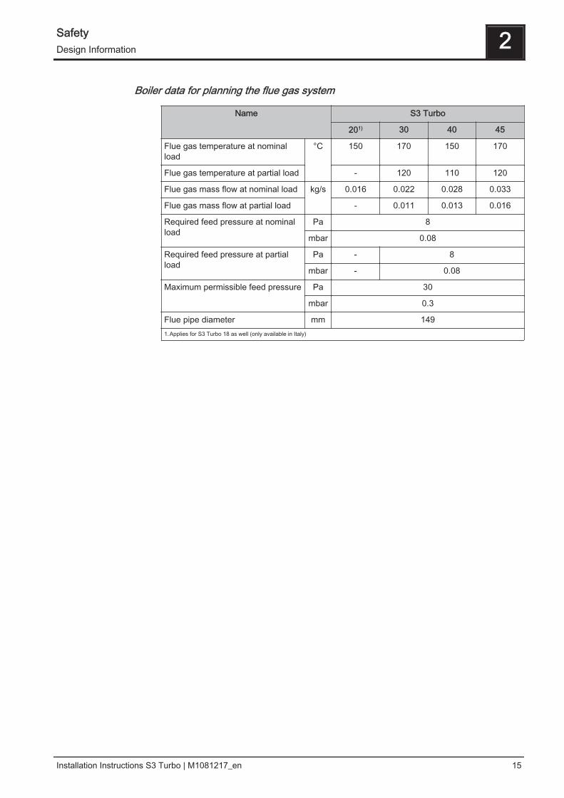
Boiler data for planning the flue gas system
Name S3 Turbo
201) 30 40 45
Flue gas temperature at nominalload
°C 150 170 150 170
Flue gas temperature at partial load - 120 110 120
Flue gas mass flow at nominal load kg/s 0.016 0.022 0.028 0.033
Flue gas mass flow at partial load - 0.011 0.013 0.016
Required feed pressure at nominalload
Pa 8
mbar 0.08
Required feed pressure at partialload
Pa - 8
mbar - 0.08
Maximum permissible feed pressure Pa 30
mbar 0.3
Flue pipe diameter mm 1491.Applies for S3 Turbo 18 as well (only available in Italy)
Safety 2Design Information
Installation Instructions S3 Turbo | M1081217_en 15
3 Technology
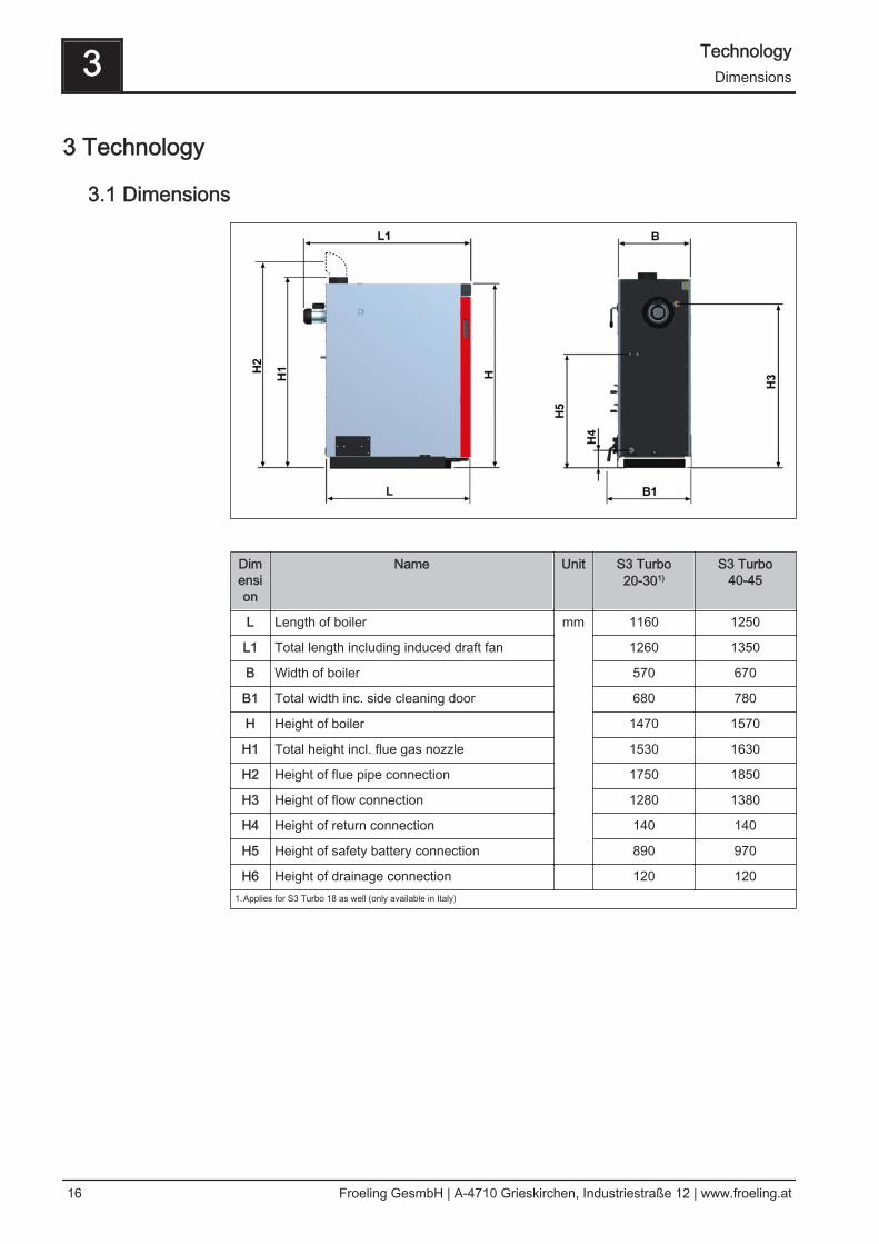
3.1 Dimensions
Dimension
Name Unit S3 Turbo20-301)
S3 Turbo40-45
L Length of boiler mm 1160 1250
L1 Total length including induced draft fan 1260 1350
B Width of boiler 570 670
B1 Total width inc. side cleaning door 680 780
H Height of boiler 1470 1570
H1 Total height incl. flue gas nozzle 1530 1630
H2 Height of flue pipe connection 1750 1850
H3 Height of flow connection 1280 1380
H4 Height of return connection 140 140
H5 Height of safety battery connection 890 970
H6 Height of drainage connection 120 1201.Applies for S3 Turbo 18 as well (only available in Italy)
3 TechnologyDimensions
16 Froeling GesmbH | A-4710 Grieskirchen, Industriestraße 12 | www.froeling.at
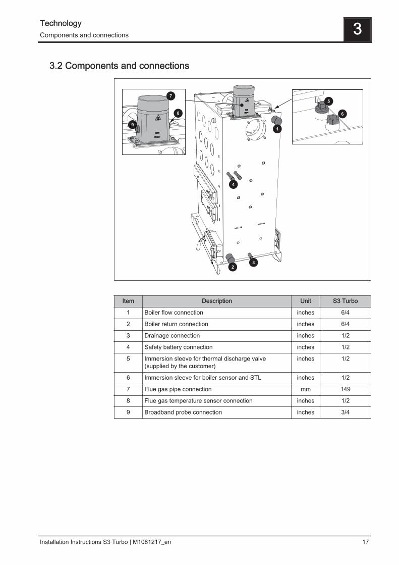
3.2 Components and connections
Item Description Unit S3 Turbo
1 Boiler flow connection inches 6/4
2 Boiler return connection inches 6/4
3 Drainage connection inches 1/2
4 Safety battery connection inches 1/2
5 Immersion sleeve for thermal discharge valve(supplied by the customer)
inches 1/2
6 Immersion sleeve for boiler sensor and STL inches 1/2
7 Flue gas pipe connection mm 149
8 Flue gas temperature sensor connection inches 1/2
9 Broadband probe connection inches 3/4
Technology 3Components and connections
Installation Instructions S3 Turbo | M1081217_en 17
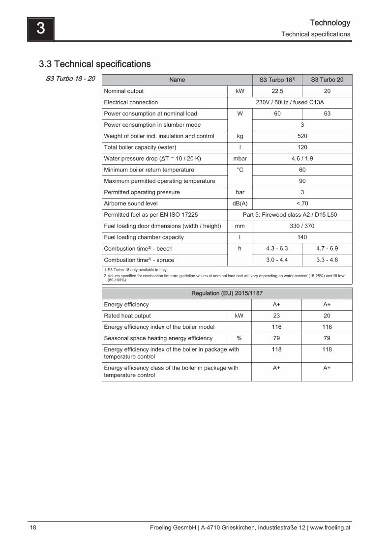
3.3 Technical specificationsName S3 Turbo 181) S3 Turbo 20
Nominal output kW 22.5 20
Electrical connection 230V / 50Hz / fused C13A
Power consumption at nominal load W 60 63
Power consumption in slumber mode 3
Weight of boiler incl. insulation and control kg 520
Total boiler capacity (water) l 120
Water pressure drop (ΔT = 10 / 20 K) mbar 4.6 / 1.9
Minimum boiler return temperature °C 60
Maximum permitted operating temperature 90
Permitted operating pressure bar 3
Airborne sound level dB(A) < 70
Permitted fuel as per EN ISO 17225 Part 5: Firewood class A2 / D15 L50
Fuel loading door dimensions (width / height) mm 330 / 370
Fuel loading chamber capacity l 140
Combustion time2) - beech h 4.3 - 6.3 4.7 - 6.9
Combustion time2) - spruce 3.0 - 4.4 3.3 - 4.81.S3 Turbo 18 only available in Italy2.Values specified for combustion time are guideline values at nominal load and will vary depending on water content (15-25%) and fill level
(80-100%)
Regulation (EU) 2015/1187
Energy efficiency A+ A+
Rated heat output kW 23 20
Energy efficiency index of the boiler model 116 116
Seasonal space heating energy efficiency % 79 79
Energy efficiency index of the boiler in package withtemperature control
118 118
Energy efficiency class of the boiler in package withtemperature control
A+ A+
S3 Turbo 18 - 20
3 TechnologyTechnical specifications
18 Froeling GesmbH | A-4710 Grieskirchen, Industriestraße 12 | www.froeling.at
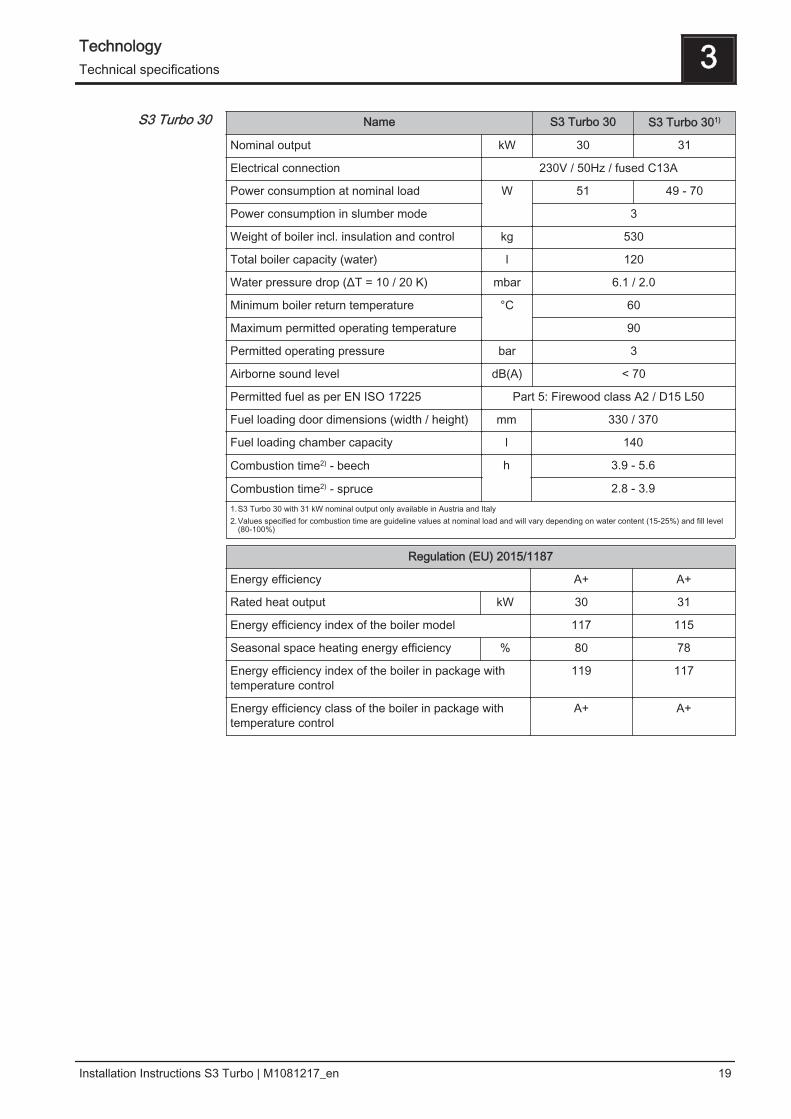
Name S3 Turbo 30 S3 Turbo 301)
Nominal output kW 30 31
Electrical connection 230V / 50Hz / fused C13A
Power consumption at nominal load W 51 49 - 70
Power consumption in slumber mode 3
Weight of boiler incl. insulation and control kg 530
Total boiler capacity (water) l 120
Water pressure drop (ΔT = 10 / 20 K) mbar 6.1 / 2.0
Minimum boiler return temperature °C 60
Maximum permitted operating temperature 90
Permitted operating pressure bar 3
Airborne sound level dB(A) < 70
Permitted fuel as per EN ISO 17225 Part 5: Firewood class A2 / D15 L50
Fuel loading door dimensions (width / height) mm 330 / 370
Fuel loading chamber capacity l 140
Combustion time2) - beech h 3.9 - 5.6
Combustion time2) - spruce 2.8 - 3.91.S3 Turbo 30 with 31 kW nominal output only available in Austria and Italy2.Values specified for combustion time are guideline values at nominal load and will vary depending on water content (15-25%) and fill level
(80-100%)
Regulation (EU) 2015/1187
Energy efficiency A+ A+
Rated heat output kW 30 31
Energy efficiency index of the boiler model 117 115
Seasonal space heating energy efficiency % 80 78
Energy efficiency index of the boiler in package withtemperature control
119 117
Energy efficiency class of the boiler in package withtemperature control
A+ A+
S3 Turbo 30
Technology 3Technical specifications
Installation Instructions S3 Turbo | M1081217_en 19
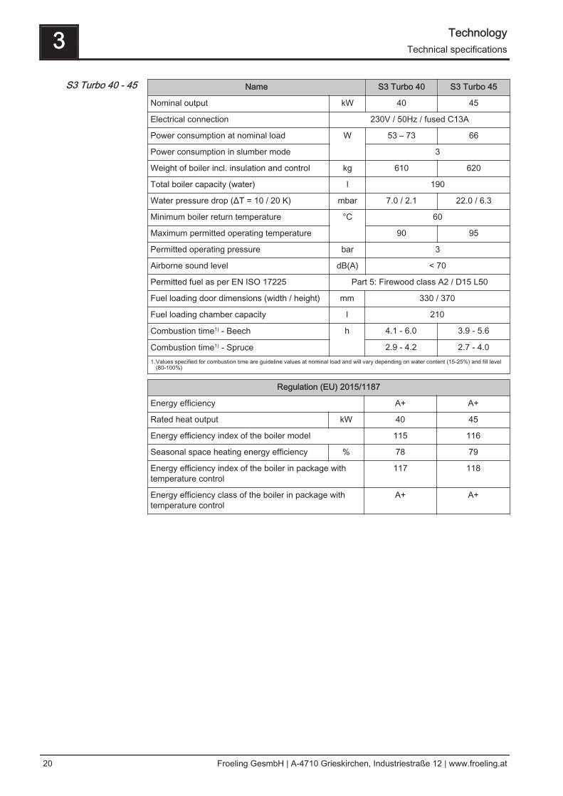
Name S3 Turbo 40 S3 Turbo 45
Nominal output kW 40 45
Electrical connection 230V / 50Hz / fused C13A
Power consumption at nominal load W 53 – 73 66
Power consumption in slumber mode 3
Weight of boiler incl. insulation and control kg 610 620
Total boiler capacity (water) l 190
Water pressure drop (ΔT = 10 / 20 K) mbar 7.0 / 2.1 22.0 / 6.3
Minimum boiler return temperature °C 60
Maximum permitted operating temperature 90 95
Permitted operating pressure bar 3
Airborne sound level dB(A) < 70
Permitted fuel as per EN ISO 17225 Part 5: Firewood class A2 / D15 L50
Fuel loading door dimensions (width / height) mm 330 / 370
Fuel loading chamber capacity l 210
Combustion time1) - Beech h 4.1 - 6.0 3.9 - 5.6
Combustion time1) - Spruce 2.9 - 4.2 2.7 - 4.01.Values specified for combustion time are guideline values at nominal load and will vary depending on water content (15-25%) and fill level
(80-100%)
Regulation (EU) 2015/1187
Energy efficiency A+ A+
Rated heat output kW 40 45
Energy efficiency index of the boiler model 115 116
Seasonal space heating energy efficiency % 78 79
Energy efficiency index of the boiler in package withtemperature control
117 118
Energy efficiency class of the boiler in package withtemperature control
A+ A+
S3 Turbo 40 - 45
3 TechnologyTechnical specifications
20 Froeling GesmbH | A-4710 Grieskirchen, Industriestraße 12 | www.froeling.at
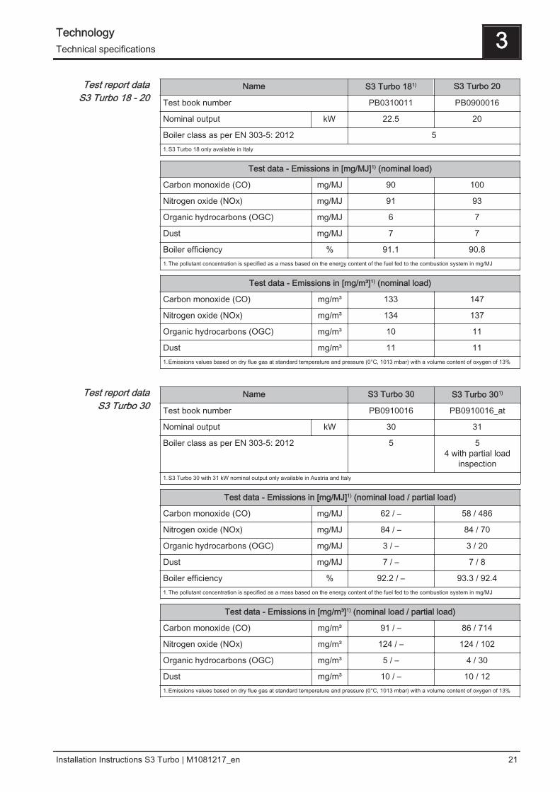
Name S3 Turbo 181) S3 Turbo 20
Test book number PB0310011 PB0900016
Nominal output kW 22.5 20
Boiler class as per EN 303-5: 2012 51.S3 Turbo 18 only available in Italy
Test data - Emissions in [mg/MJ]1) (nominal load)
Carbon monoxide (CO) mg/MJ 90 100
Nitrogen oxide (NOx) mg/MJ 91 93
Organic hydrocarbons (OGC) mg/MJ 6 7
Dust mg/MJ 7 7
Boiler efficiency % 91.1 90.81.The pollutant concentration is specified as a mass based on the energy content of the fuel fed to the combustion system in mg/MJ
Test data - Emissions in [mg/m³]1) (nominal load)
Carbon monoxide (CO) mg/m³ 133 147
Nitrogen oxide (NOx) mg/m³ 134 137
Organic hydrocarbons (OGC) mg/m³ 10 11
Dust mg/m³ 11 111.Emissions values based on dry flue gas at standard temperature and pressure (0°C, 1013 mbar) with a volume content of oxygen of 13%
Name S3 Turbo 30 S3 Turbo 301)
Test book number PB0910016 PB0910016_at
Nominal output kW 30 31
Boiler class as per EN 303-5: 2012 5 54 with partial load
inspection1.S3 Turbo 30 with 31 kW nominal output only available in Austria and Italy
Test data - Emissions in [mg/MJ]1) (nominal load / partial load)
Carbon monoxide (CO) mg/MJ 62 / – 58 / 486
Nitrogen oxide (NOx) mg/MJ 84 / – 84 / 70
Organic hydrocarbons (OGC) mg/MJ 3 / – 3 / 20
Dust mg/MJ 7 / – 7 / 8
Boiler efficiency % 92.2 / – 93.3 / 92.41.The pollutant concentration is specified as a mass based on the energy content of the fuel fed to the combustion system in mg/MJ
Test data - Emissions in [mg/m³]1) (nominal load / partial load)
Carbon monoxide (CO) mg/m³ 91 / – 86 / 714
Nitrogen oxide (NOx) mg/m³ 124 / – 124 / 102
Organic hydrocarbons (OGC) mg/m³ 5 / – 4 / 30
Dust mg/m³ 10 / – 10 / 121.Emissions values based on dry flue gas at standard temperature and pressure (0°C, 1013 mbar) with a volume content of oxygen of 13%
Test report dataS3 Turbo 18 - 20
Test report dataS3 Turbo 30
Technology 3Technical specifications
Installation Instructions S3 Turbo | M1081217_en 21
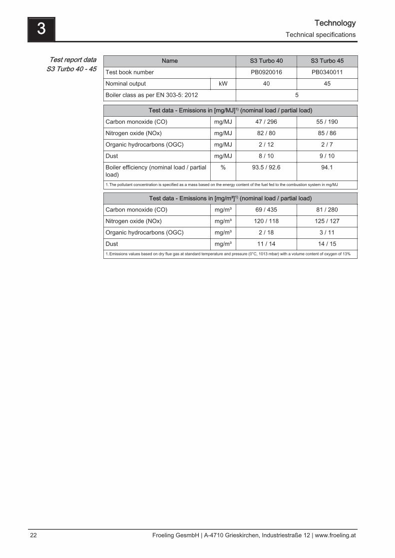
Name S3 Turbo 40 S3 Turbo 45
Test book number PB0920016 PB0340011
Nominal output kW 40 45
Boiler class as per EN 303-5: 2012 5
Test data - Emissions in [mg/MJ]1) (nominal load / partial load)
Carbon monoxide (CO) mg/MJ 47 / 296 55 / 190
Nitrogen oxide (NOx) mg/MJ 82 / 80 85 / 86
Organic hydrocarbons (OGC) mg/MJ 2 / 12 2 / 7
Dust mg/MJ 8 / 10 9 / 10
Boiler efficiency (nominal load / partialload)
% 93.5 / 92.6 94.1
1.The pollutant concentration is specified as a mass based on the energy content of the fuel fed to the combustion system in mg/MJ
Test data - Emissions in [mg/m³]1) (nominal load / partial load)
Carbon monoxide (CO) mg/m³ 69 / 435 81 / 280
Nitrogen oxide (NOx) mg/m³ 120 / 118 125 / 127
Organic hydrocarbons (OGC) mg/m³ 2 / 18 3 / 11
Dust mg/m³ 11 / 14 14 / 151.Emissions values based on dry flue gas at standard temperature and pressure (0°C, 1013 mbar) with a volume content of oxygen of 13%
Test report dataS3 Turbo 40 - 45
3 TechnologyTechnical specifications
22 Froeling GesmbH | A-4710 Grieskirchen, Industriestraße 12 | www.froeling.at
4 Assembly
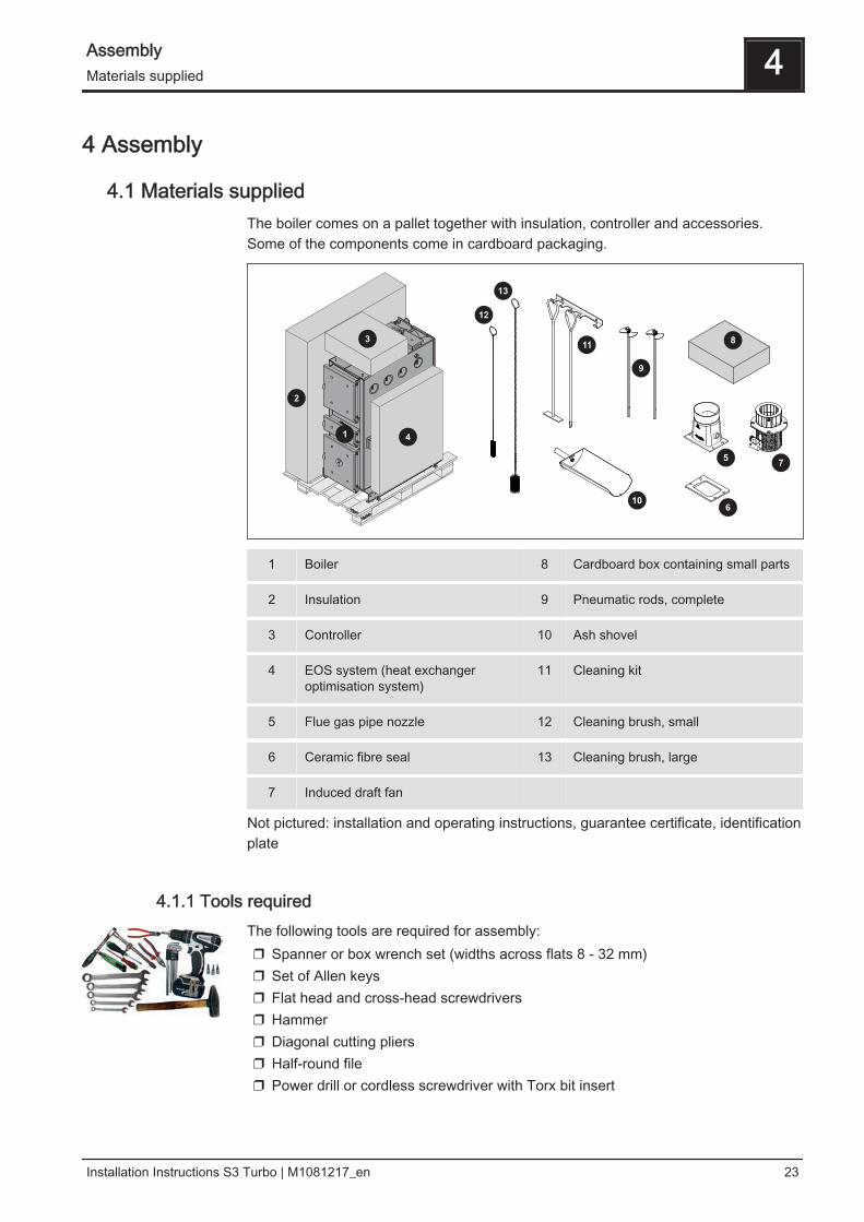
4.1 Materials suppliedThe boiler comes on a pallet together with insulation, controller and accessories.Some of the components come in cardboard packaging.
1 Boiler 8 Cardboard box containing small parts
2 Insulation 9 Pneumatic rods, complete
3 Controller 10 Ash shovel
4 EOS system (heat exchanger optimisation system)
11 Cleaning kit
5 Flue gas pipe nozzle 12 Cleaning brush, small
6 Ceramic fibre seal 13 Cleaning brush, large
7 Induced draft fan
Not pictured: installation and operating instructions, guarantee certificate, identificationplate
4.1.1 Tools requiredThe following tools are required for assembly:❒ Spanner or box wrench set (widths across flats 8 - 32 mm)❒ Set of Allen keys❒ Flat head and cross-head screwdrivers❒ Hammer❒ Diagonal cutting pliers❒ Half-round file❒ Power drill or cordless screwdriver with Torx bit insert
Assembly 4Materials supplied
Installation Instructions S3 Turbo | M1081217_en 23

4.2 Positioning
NOTICE
Damage to components if handled incorrectly
❒ Follow the transport instructions on the packaging❒ Transport components with care to avoid damage❒ Protect the packaging against damp conditions❒ Pay attention to the pallet's centre of gravity when lifting
❒ Position a fork-lift or similar lifting device at the pallet and bring in the components
If the boiler cannot be brought in on the pallet:❒ remove the cardboard and take the boiler off the pallet
⇨ See "Remove boiler from pallet" [page 25]
Positioning using a crane
❒ Attach the crane hook to the attachment point correctly and position the boiler
4.2.1 Temporary storageIf the system is to be assembled at a later stage:❒ Store components at a protected location, which is dry and free from dust
➥ Damp conditions and frost can damage components, particularly electric ones!
4 AssemblyPositioning
24 Froeling GesmbH | A-4710 Grieskirchen, Industriestraße 12 | www.froeling.at
4.3 Setting up in the boiler room
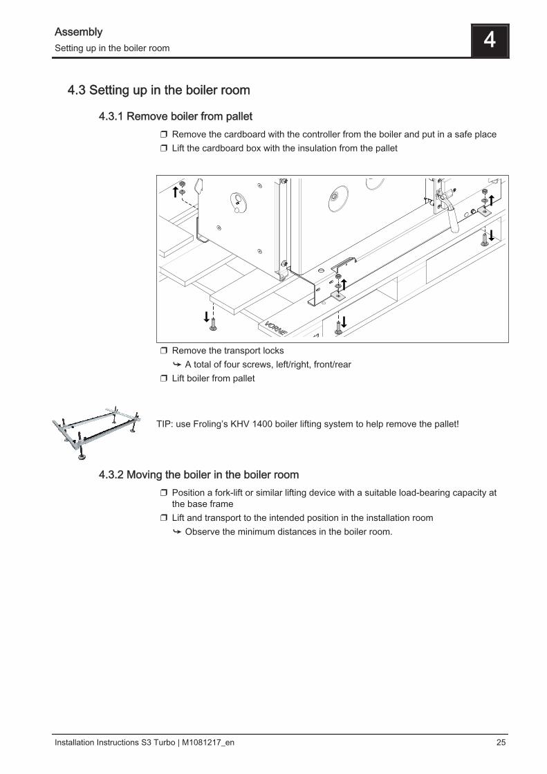
4.3.1 Remove boiler from pallet❒ Remove the cardboard with the controller from the boiler and put in a safe place❒ Lift the cardboard box with the insulation from the pallet
❒ Remove the transport locks➥ A total of four screws, left/right, front/rear
❒ Lift boiler from pallet TIP: use Froling’s KHV 1400 boiler lifting system to help remove the pallet!
4.3.2 Moving the boiler in the boiler room❒ Position a fork-lift or similar lifting device with a suitable load-bearing capacity at
the base frame❒ Lift and transport to the intended position in the installation room
➥ Observe the minimum distances in the boiler room.
Assembly 4Setting up in the boiler room
Installation Instructions S3 Turbo | M1081217_en 25
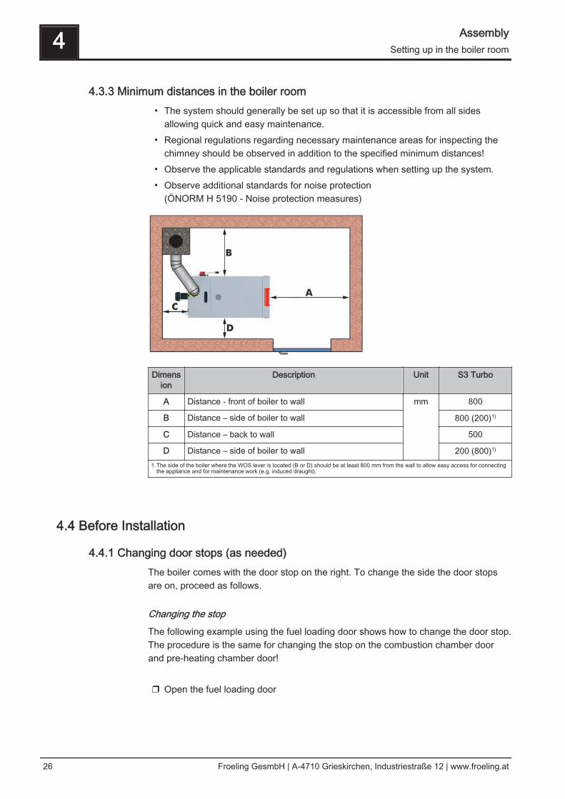
4.3.3 Minimum distances in the boiler room▪ The system should generally be set up so that it is accessible from all sides
allowing quick and easy maintenance.▪ Regional regulations regarding necessary maintenance areas for inspecting the
chimney should be observed in addition to the specified minimum distances!▪ Observe the applicable standards and regulations when setting up the system.▪ Observe additional standards for noise protection
(ÖNORM H 5190 - Noise protection measures)
Dimension
Description Unit S3 Turbo
A Distance - front of boiler to wall mm 800
B Distance – side of boiler to wall 800 (200)1)
C Distance – back to wall 500
D Distance – side of boiler to wall 200 (800)1)
1.The side of the boiler where the WOS lever is located (B or D) should be at least 800 mm from the wall to allow easy access for connectingthe appliance and for maintenance work (e.g. induced draught).
4.4 Before Installation
4.4.1 Changing door stops (as needed)The boiler comes with the door stop on the right. To change the side the door stopsare on, proceed as follows.
Changing the stop
The following example using the fuel loading door shows how to change the door stop.The procedure is the same for changing the stop on the combustion chamber doorand pre-heating chamber door! ❒ Open the fuel loading door
4 AssemblySetting up in the boiler room
26 Froeling GesmbH | A-4710 Grieskirchen, Industriestraße 12 | www.froeling.at
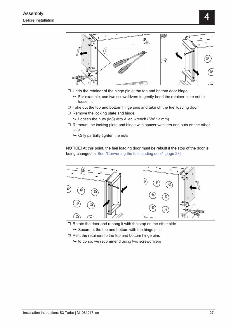
❒ Undo the retainer of the hinge pin at the top and bottom door hinge➥ For example, use two screwdrivers to gently bend the retainer plate out to
loosen it❒ Take out the top and bottom hinge pins and take off the fuel loading door❒ Remove the locking plate and hinge
➥ Loosen the nuts (M8) with Allen wrench (SW 13 mm)❒ Remount the locking plate and hinge with spacer washers and nuts on the other
side➥ Only partially tighten the nuts
NOTICE! At this point, the fuel loading door must be rebuilt if the stop of the door isbeing changed. ⇨ See "Converting the fuel loading door" [page 28]
❒ Rotate the door and rehang it with the stop on the other side➥ Secure at the top and bottom with the hinge pins
❒ Refit the retainers to the top and bottom hinge pins➥ to do so, we recommend using two screwdrivers
Assembly 4Before Installation
Installation Instructions S3 Turbo | M1081217_en 27
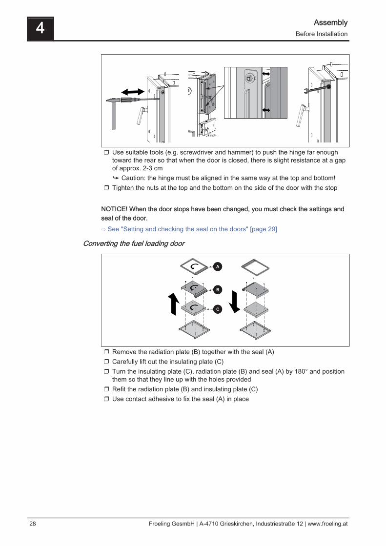
❒ Use suitable tools (e.g. screwdriver and hammer) to push the hinge far enoughtoward the rear so that when the door is closed, there is slight resistance at a gapof approx. 2-3 cm➥ Caution: the hinge must be aligned in the same way at the top and bottom!
❒ Tighten the nuts at the top and the bottom on the side of the door with the stop NOTICE! When the door stops have been changed, you must check the settings andseal of the door.⇨ See "Setting and checking the seal on the doors" [page 29]
Converting the fuel loading door
❒ Remove the radiation plate (B) together with the seal (A)❒ Carefully lift out the insulating plate (C)❒ Turn the insulating plate (C), radiation plate (B) and seal (A) by 180° and position
them so that they line up with the holes provided❒ Refit the radiation plate (B) and insulating plate (C)❒ Use contact adhesive to fix the seal (A) in place
4 AssemblyBefore Installation
28 Froeling GesmbH | A-4710 Grieskirchen, Industriestraße 12 | www.froeling.at
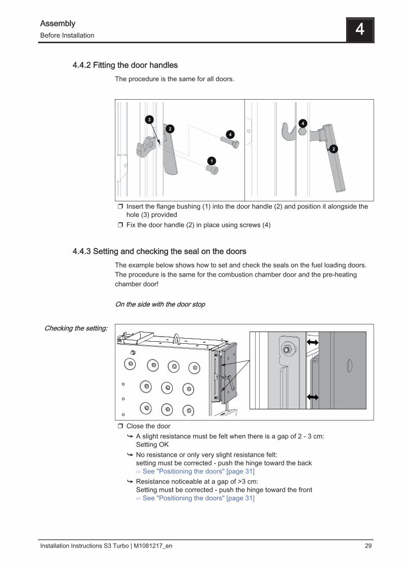
4.4.2 Fitting the door handlesThe procedure is the same for all doors.
❒ Insert the flange bushing (1) into the door handle (2) and position it alongside thehole (3) provided
❒ Fix the door handle (2) in place using screws (4)
4.4.3 Setting and checking the seal on the doorsThe example below shows how to set and check the seals on the fuel loading doors.The procedure is the same for the combustion chamber door and the pre-heatingchamber door!
On the side with the door stop
❒ Close the door➥ A slight resistance must be felt when there is a gap of 2 - 3 cm:
Setting OK➥ No resistance or only very slight resistance felt:
setting must be corrected - push the hinge toward the back⇨ See "Positioning the doors" [page 31]
➥ Resistance noticeable at a gap of >3 cm: Setting must be corrected - push the hinge toward the front⇨ See "Positioning the doors" [page 31]
Checking the setting:
Assembly 4Before Installation
Installation Instructions S3 Turbo | M1081217_en 29
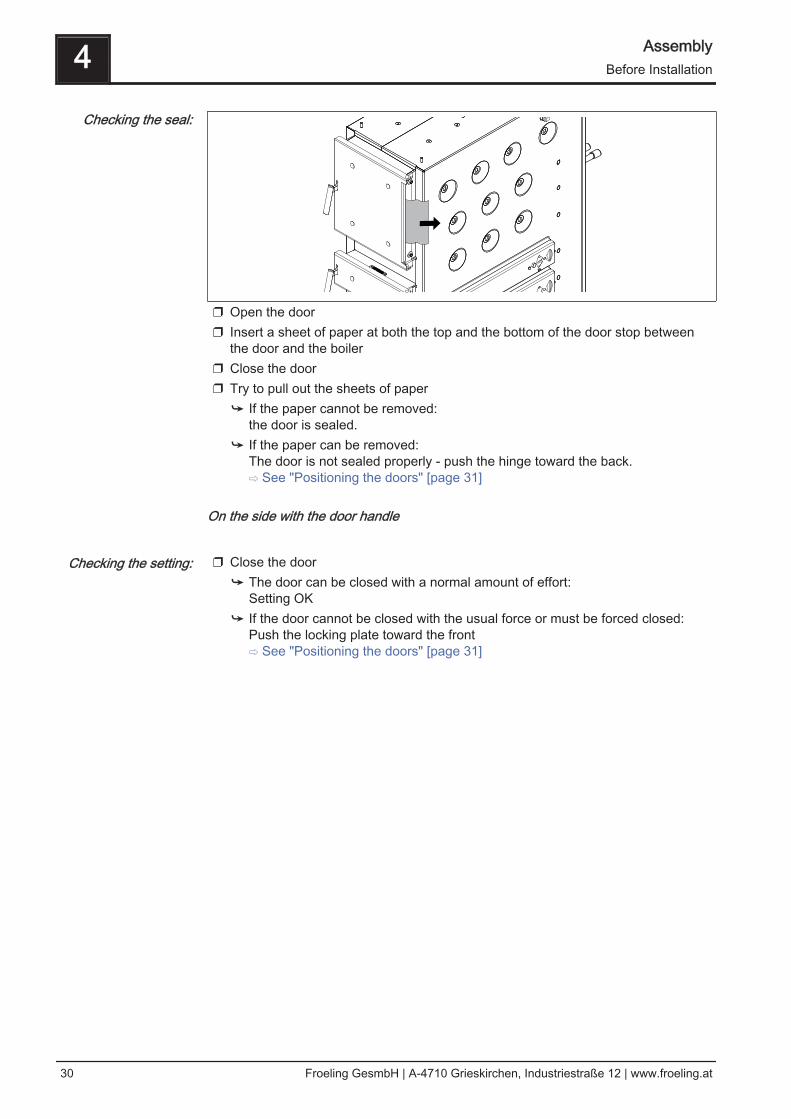
❒ Open the door❒ Insert a sheet of paper at both the top and the bottom of the door stop between
the door and the boiler❒ Close the door❒ Try to pull out the sheets of paper
➥ If the paper cannot be removed: the door is sealed.
➥ If the paper can be removed: The door is not sealed properly - push the hinge toward the back.⇨ See "Positioning the doors" [page 31]
On the side with the door handle
❒ Close the door
➥ The door can be closed with a normal amount of effort: Setting OK
➥ If the door cannot be closed with the usual force or must be forced closed: Push the locking plate toward the front⇨ See "Positioning the doors" [page 31]
Checking the seal:
Checking the setting:
4 AssemblyBefore Installation
30 Froeling GesmbH | A-4710 Grieskirchen, Industriestraße 12 | www.froeling.at
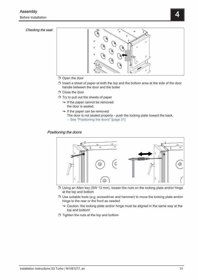
❒ Open the door❒ Insert a sheet of paper at both the top and the bottom area at the side of the door
handle between the door and the boiler❒ Close the door❒ Try to pull out the sheets of paper
➥ If the paper cannot be removed: the door is sealed.
➥ If the paper can be removed: The door is not sealed properly - push the locking plate toward the back.⇨ See "Positioning the doors" [page 31]
Positioning the doors
❒ Using an Allen key (SW 13 mm), loosen the nuts on the locking plate and/or hingeat the top and bottom
❒ Use suitable tools (e.g. screwdriver and hammer) to move the locking plate and/orhinge to the rear or the front as needed➥ Caution: the locking plate and/or hinge must be aligned in the same way at the
top and bottom!❒ Tighten the nuts at the top and bottom
Checking the seal:
Assembly 4Before Installation
Installation Instructions S3 Turbo | M1081217_en 31
4.5 Installing the boiler
4.5.1 Assembly overview
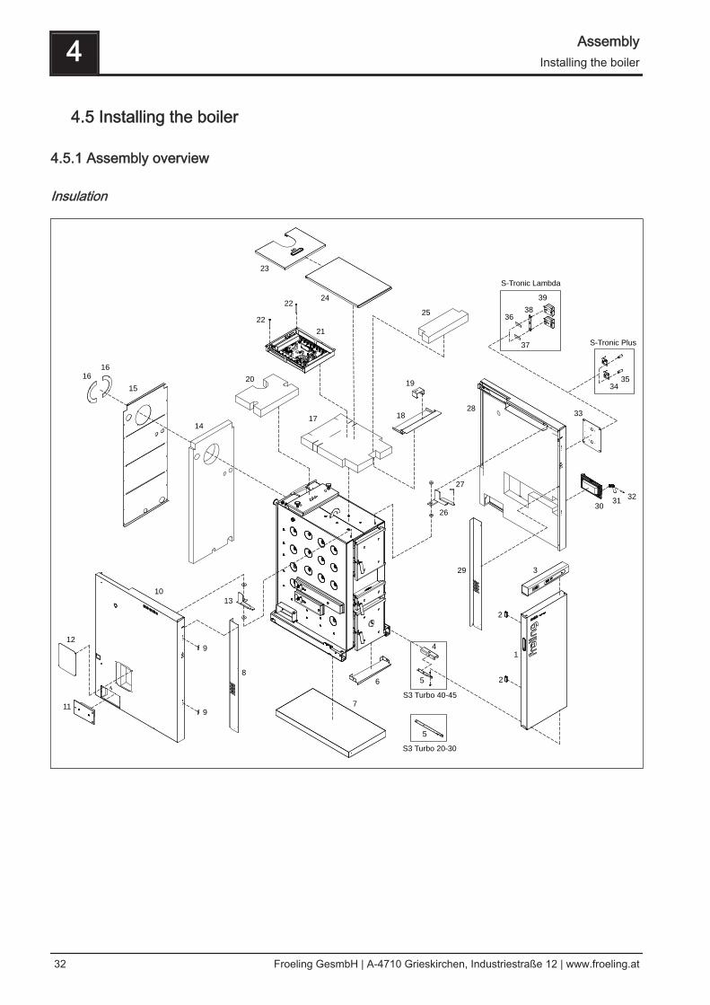
Insulation
1
2
2
3
4
5
5
6
7
10
9
9
8
11
12
13
14
15
16
16
17
20
21
22
22
18
19
23
24
25
26
27
28
29
3031
32
33
35
34
36
38
39
S3 Turbo 40-45
S3 Turbo 20-30
S-Tronic Lambda
S-Tronic Plus37
4 AssemblyInstalling the boiler
32 Froeling GesmbH | A-4710 Grieskirchen, Industriestraße 12 | www.froeling.at

Item Quantity[units]
Name Item Quantity[units]
Name
1 1 Insulated door, complete 21 1 Controller box, complete
2 2 Magnetic latches 22 2 Hexagonal screw M6 x 100
3 1 Control, complete 23 1 Insulating cover, back
4 1 U-plate – S3 Turbo 40/45 24 1 Controller cover
5 1 Lower door bracket 25 1 Heat insulation mat, top/front
6 1 Cover plate, insulated door, bottom 26 1 Bracket, right
7 1 Complete floor insulation 27 1 Hinge pin, insulated door
8 1 Insulation cover plate, left 28 1 Insulating side panel, right, complete
9 2 Counter plate for magnetic latches 29 1 Insulation cover plate, right
10 1 Insulating side panel, left, complete 30 1 Side cleaning door, complete
11 1 Blanking plate, side cleaning door 31 1 Door handle, cleaning door
12 1 Cover plate 32 1 Round-head screw M8 x 30
13 1 Bracket, left 33 1 Cover plate
14 1 Thermal insulation, rear 34 2 Air flap manual controller(only for S-Tronic Plus)
15 1 Back panel, complete 35 2 Air flap handle(only for S-Tronic Plus)
16 2 Cover plate for ID fan 36 1 Sticker, "Primary air actuator" (only with S-Tronic Lambda)
17 1 Heat insulation mat, top 37 1 Sticker, "Secondary air actuator"(only with S-Tronic Lambda)
18 1 Upper spacer plate 38 1 Torque support(only with S-Tronic Lambda)
19 1 Door contact switch incl. cable 39 2 Servo-motor LM 24AP5-F/300.1(only with S-Tronic Lambda)
20 1 Heat insulation mat, top/rear
Assembly 4Installing the boiler
Installation Instructions S3 Turbo | M1081217_en 33
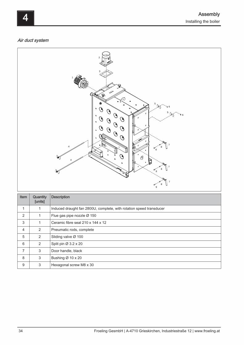
Air duct system
1
2
3
4
4
5
6
6
5
7
8
9
7
8
9
7
8
9
Item Quantity[units]
Description
1 1 Induced draught fan 2800U, complete, with rotation speed transducer
2 1 Flue gas pipe nozzle Ø 150
3 1 Ceramic fibre seal 210 x 144 x 12
4 2 Pneumatic rods, complete
5 2 Sliding valve Ø 100
6 2 Split pin Ø 3.2 x 20
7 3 Door handle, black
8 3 Bushing Ø 10 x 20
9 3 Hexagonal screw M8 x 30
4 AssemblyInstalling the boiler
34 Froeling GesmbH | A-4710 Grieskirchen, Industriestraße 12 | www.froeling.at
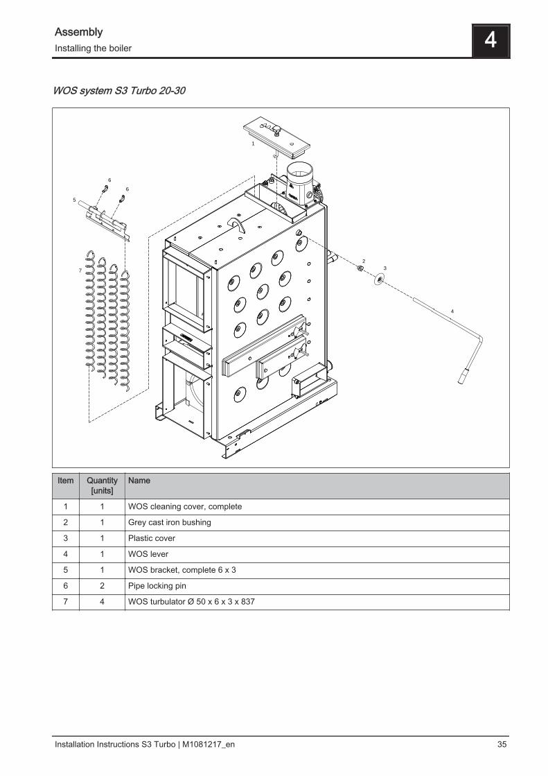
WOS system S3 Turbo 20-30
1
2
3
4
5
6
6
7
Item Quantity[units]
Name
1 1 WOS cleaning cover, complete
2 1 Grey cast iron bushing
3 1 Plastic cover
4 1 WOS lever
5 1 WOS bracket, complete 6 x 3
6 2 Pipe locking pin
7 4 WOS turbulator Ø 50 x 6 x 3 x 837
Assembly 4Installing the boiler
Installation Instructions S3 Turbo | M1081217_en 35
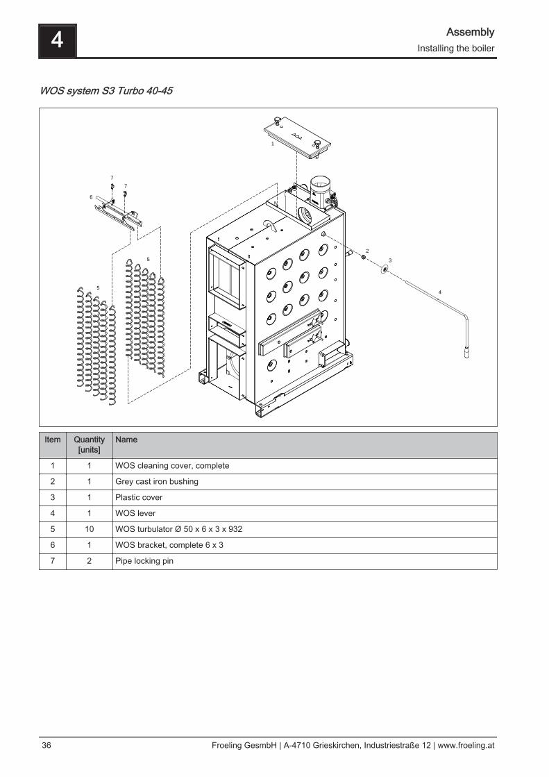
WOS system S3 Turbo 40-45
1
2
3
4
6
7
7
5
5
Item Quantity[units]
Name
1 1 WOS cleaning cover, complete
2 1 Grey cast iron bushing
3 1 Plastic cover
4 1 WOS lever
5 10 WOS turbulator Ø 50 x 6 x 3 x 932
6 1 WOS bracket, complete 6 x 3
7 2 Pipe locking pin
4 AssemblyInstalling the boiler
36 Froeling GesmbH | A-4710 Grieskirchen, Industriestraße 12 | www.froeling.at
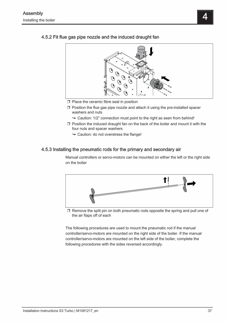
4.5.2 Fit flue gas pipe nozzle and the induced draught fan
❒ Place the ceramic fibre seal in position❒ Position the flue gas pipe nozzle and attach it using the pre-installed spacer
washers and nuts➥ Caution: 1/2” connection must point to the right as seen from behind!
❒ Position the induced draught fan on the back of the boiler and mount it with thefour nuts and spacer washers➥ Caution: do not overstress the flange!
4.5.3 Installing the pneumatic rods for the primary and secondary airManual controllers or servo-motors can be mounted on either the left or the right sideon the boiler
❒ Remove the split pin on both pneumatic rods opposite the spring and pull one ofthe air flaps off of each
The following procedures are used to mount the pneumatic rod if the manualcontroller/servo-motors are mounted on the right side of the boiler. If the manualcontroller/servo-motors are mounted on the left side of the boiler, complete thefollowing procedures with the sides reversed accordingly.
Assembly 4Installing the boiler
Installation Instructions S3 Turbo | M1081217_en 37
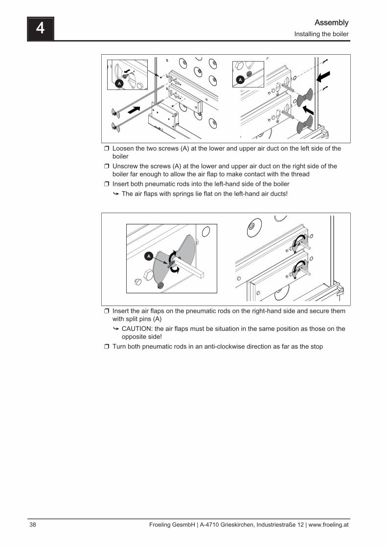
❒ Loosen the two screws (A) at the lower and upper air duct on the left side of theboiler
❒ Unscrew the screws (A) at the lower and upper air duct on the right side of theboiler far enough to allow the air flap to make contact with the thread
❒ Insert both pneumatic rods into the left-hand side of the boiler➥ The air flaps with springs lie flat on the left-hand air ducts!
❒ Insert the air flaps on the pneumatic rods on the right-hand side and secure themwith split pins (A)➥ CAUTION: the air flaps must be situation in the same position as those on the
opposite side!❒ Turn both pneumatic rods in an anti-clockwise direction as far as the stop
4 AssemblyInstalling the boiler
38 Froeling GesmbH | A-4710 Grieskirchen, Industriestraße 12 | www.froeling.at
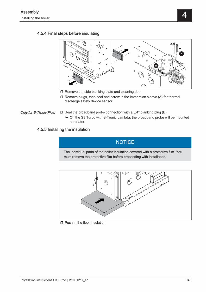
4.5.4 Final steps before insulating
❒ Remove the side blanking plate and cleaning door❒ Remove plugs, then seal and screw in the immersion sleeve (A) for thermal
discharge safety device sensor ❒ Seal the broadband probe connection with a 3/4" blanking plug (B)
➥ On the S3 Turbo with S-Tronic Lambda, the broadband probe will be mountedhere later
4.5.5 Installing the insulation
NOTICE
The individual parts of the boiler insulation covered with a protective film. Youmust remove the protective film before proceeding with installation.
❒ Push in the floor insulation
Only for S-Tronic Plus:
Assembly 4Installing the boiler
Installation Instructions S3 Turbo | M1081217_en 39
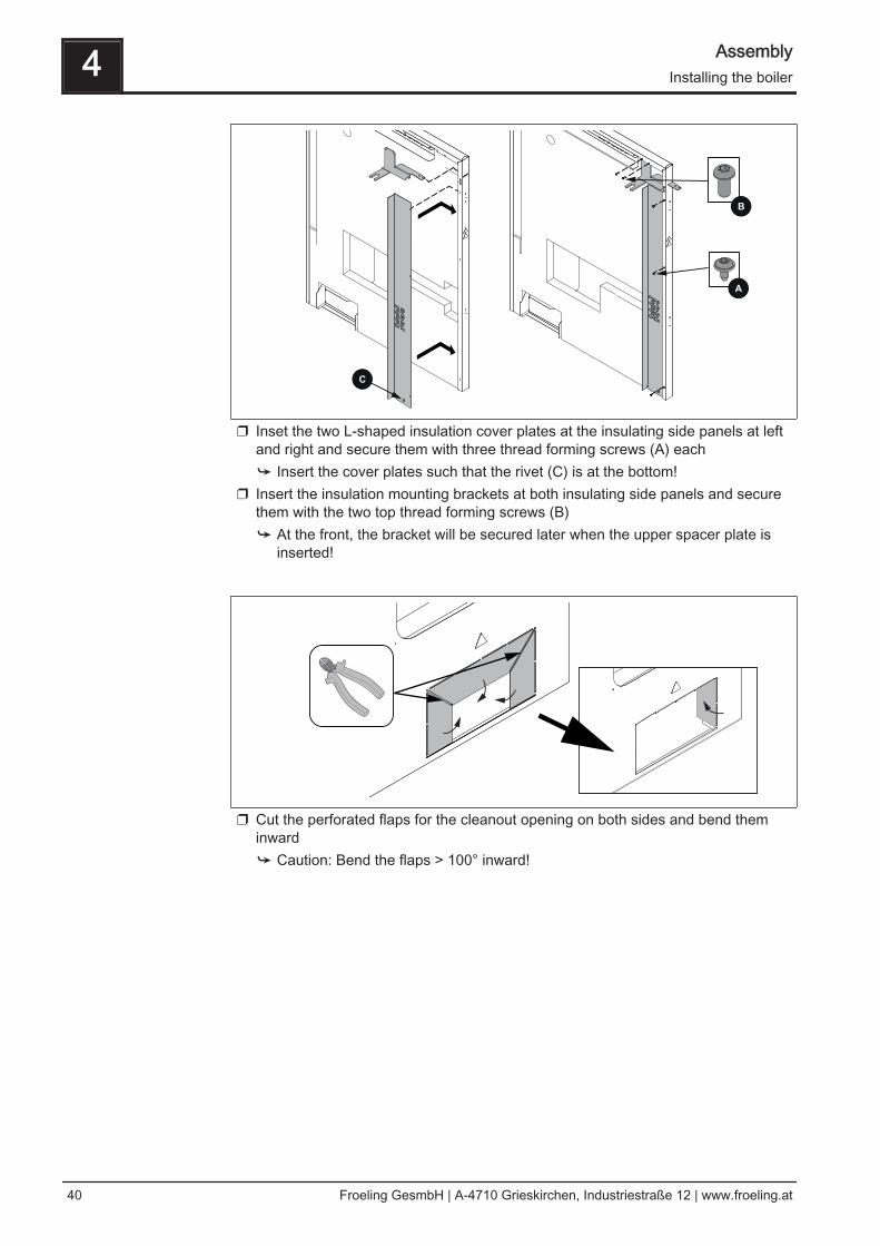
❒ Inset the two L-shaped insulation cover plates at the insulating side panels at leftand right and secure them with three thread forming screws (A) each➥ Insert the cover plates such that the rivet (C) is at the bottom!
❒ Insert the insulation mounting brackets at both insulating side panels and securethem with the two top thread forming screws (B)➥ At the front, the bracket will be secured later when the upper spacer plate is
inserted!
❒ Cut the perforated flaps for the cleanout opening on both sides and bend theminward➥ Caution: Bend the flaps > 100° inward!
4 AssemblyInstalling the boiler
40 Froeling GesmbH | A-4710 Grieskirchen, Industriestraße 12 | www.froeling.at
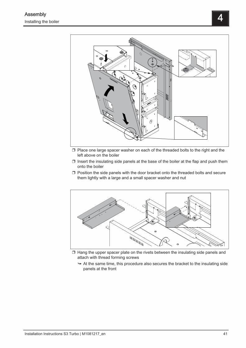
❒ Place one large spacer washer on each of the threaded bolts to the right and theleft above on the boiler
❒ Insert the insulating side panels at the base of the boiler at the flap and push themonto the boiler
❒ Position the side panels with the door bracket onto the threaded bolts and securethem lightly with a large and a small spacer washer and nut
❒ Hang the upper spacer plate on the rivets between the insulating side panels andattach with thread forming screws➥ At the same time, this procedure also secures the bracket to the insulating side
panels at the front
Assembly 4Installing the boiler
Installation Instructions S3 Turbo | M1081217_en 41
4.5.6 Installing the door switch
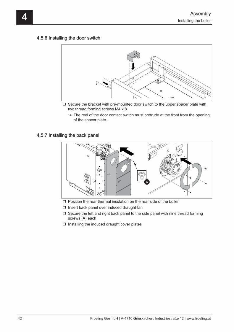
❒ Secure the bracket with pre-mounted door switch to the upper spacer plate withtwo thread forming screws M4 x 8➥ The reel of the door contact switch must protrude at the front from the opening
of the spacer plate.
4.5.7 Installing the back panel
❒ Position the rear thermal insulation on the rear side of the boiler❒ Insert back panel over induced draught fan❒ Secure the left and right back panel to the side panel with nine thread forming
screws (A) each❒ Installing the induced draught cover plates
4 AssemblyInstalling the boiler
42 Froeling GesmbH | A-4710 Grieskirchen, Industriestraße 12 | www.froeling.at
4.5.8 Aligning the insulation and attaching the controller
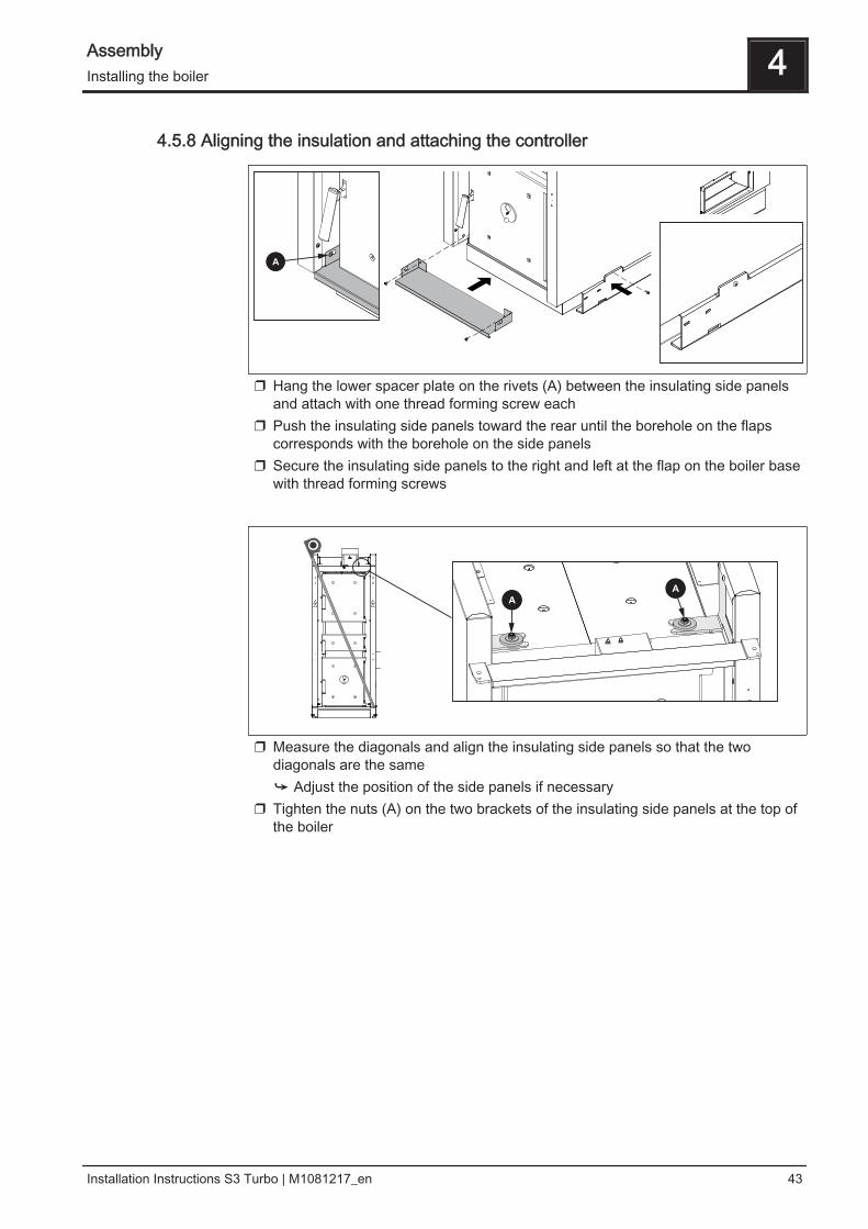
❒ Hang the lower spacer plate on the rivets (A) between the insulating side panelsand attach with one thread forming screw each
❒ Push the insulating side panels toward the rear until the borehole on the flapscorresponds with the borehole on the side panels
❒ Secure the insulating side panels to the right and left at the flap on the boiler basewith thread forming screws
❒ Measure the diagonals and align the insulating side panels so that the twodiagonals are the same➥ Adjust the position of the side panels if necessary
❒ Tighten the nuts (A) on the two brackets of the insulating side panels at the top ofthe boiler
Assembly 4Installing the boiler
Installation Instructions S3 Turbo | M1081217_en 43
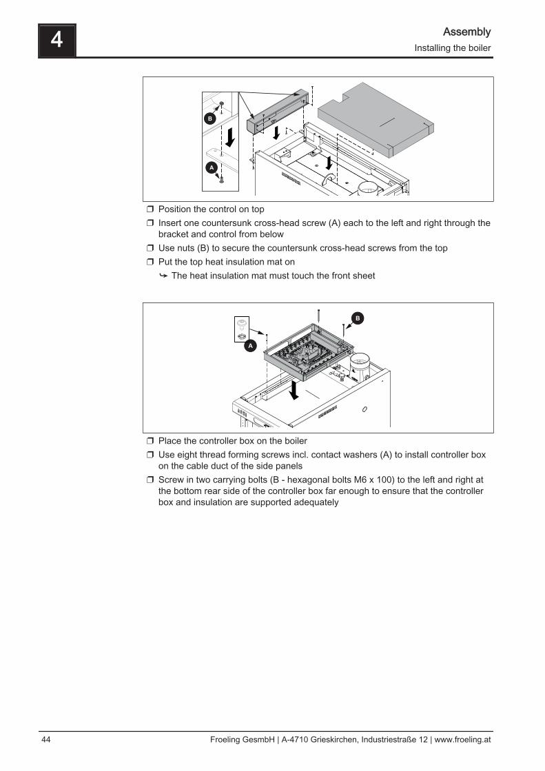
❒ Position the control on top❒ Insert one countersunk cross-head screw (A) each to the left and right through the
bracket and control from below❒ Use nuts (B) to secure the countersunk cross-head screws from the top❒ Put the top heat insulation mat on
➥ The heat insulation mat must touch the front sheet
❒ Place the controller box on the boiler❒ Use eight thread forming screws incl. contact washers (A) to install controller box
on the cable duct of the side panels❒ Screw in two carrying bolts (B - hexagonal bolts M6 x 100) to the left and right at
the bottom rear side of the controller box far enough to ensure that the controllerbox and insulation are supported adequately
4 AssemblyInstalling the boiler
44 Froeling GesmbH | A-4710 Grieskirchen, Industriestraße 12 | www.froeling.at
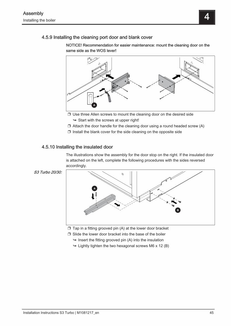
4.5.9 Installing the cleaning port door and blank coverNOTICE! Recommendation for easier maintenance: mount the cleaning door on thesame side as the WOS lever!
❒ Use three Allen screws to mount the cleaning door on the desired side➥ Start with the screws at upper right!
❒ Attach the door handle for the cleaning door using a round headed screw (A)❒ Install the blank cover for the side cleaning on the opposite side
4.5.10 Installing the insulated doorThe illustrations show the assembly for the door stop on the right. If the insulated dooris attached on the left, complete the following procedures with the sides reversedaccordingly.
❒ Tap in a fitting grooved pin (A) at the lower door bracket❒ Slide the lower door bracket into the base of the boiler
➥ Insert the fitting grooved pin (A) into the insulation➥ Lightly tighten the two hexagonal screws M6 x 12 (B)
S3 Turbo 20/30:
Assembly 4Installing the boiler
Installation Instructions S3 Turbo | M1081217_en 45
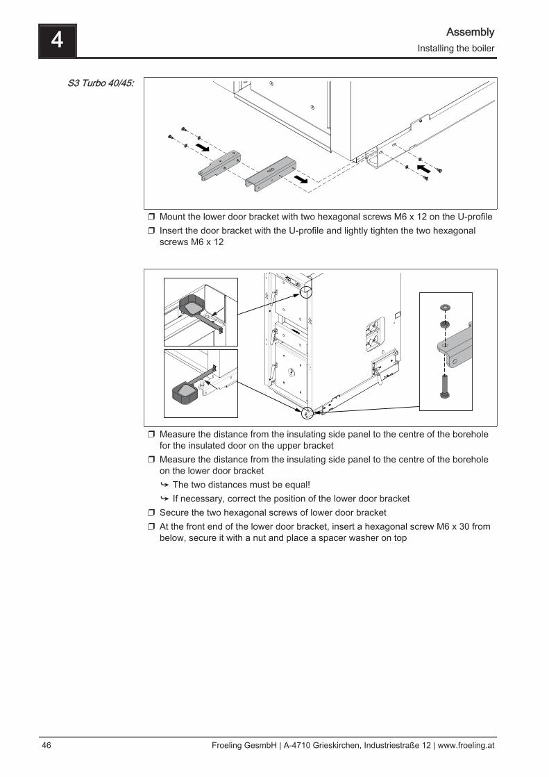
❒ Mount the lower door bracket with two hexagonal screws M6 x 12 on the U-profile❒ Insert the door bracket with the U-profile and lightly tighten the two hexagonal
screws M6 x 12
❒ Measure the distance from the insulating side panel to the centre of the boreholefor the insulated door on the upper bracket
❒ Measure the distance from the insulating side panel to the centre of the boreholeon the lower door bracket➥ The two distances must be equal!➥ If necessary, correct the position of the lower door bracket
❒ Secure the two hexagonal screws of lower door bracket❒ At the front end of the lower door bracket, insert a hexagonal screw M6 x 30 from
below, secure it with a nut and place a spacer washer on top
S3 Turbo 40/45:
4 AssemblyInstalling the boiler
46 Froeling GesmbH | A-4710 Grieskirchen, Industriestraße 12 | www.froeling.at
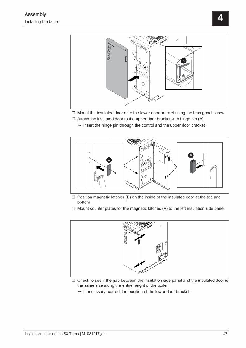
❒ Mount the insulated door onto the lower door bracket using the hexagonal screw❒ Attach the insulated door to the upper door bracket with hinge pin (A)
➥ Insert the hinge pin through the control and the upper door bracket
❒ Position magnetic latches (B) on the inside of the insulated door at the top andbottom
❒ Mount counter plates for the magnetic latches (A) to the left insulation side panel
❒ Check to see if the gap between the insulation side panel and the insulated door isthe same size along the entire height of the boiler➥ If necessary, correct the position of the lower door bracket
Assembly 4Installing the boiler
Installation Instructions S3 Turbo | M1081217_en 47
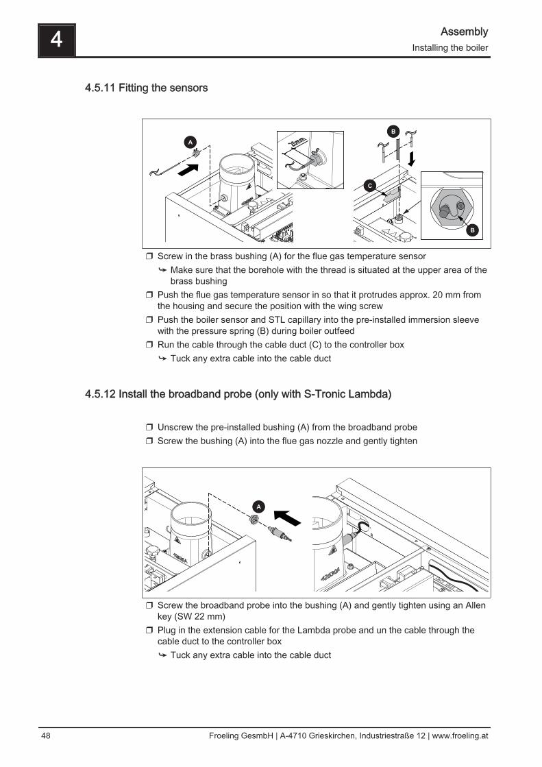
4.5.11 Fitting the sensors
❒ Screw in the brass bushing (A) for the flue gas temperature sensor➥ Make sure that the borehole with the thread is situated at the upper area of the
brass bushing❒ Push the flue gas temperature sensor in so that it protrudes approx. 20 mm from
the housing and secure the position with the wing screw❒ Push the boiler sensor and STL capillary into the pre-installed immersion sleeve
with the pressure spring (B) during boiler outfeed❒ Run the cable through the cable duct (C) to the controller box
➥ Tuck any extra cable into the cable duct
4.5.12 Install the broadband probe (only with S-Tronic Lambda) ❒ Unscrew the pre-installed bushing (A) from the broadband probe❒ Screw the bushing (A) into the flue gas nozzle and gently tighten
❒ Screw the broadband probe into the bushing (A) and gently tighten using an Allenkey (SW 22 mm)
❒ Plug in the extension cable for the Lambda probe and un the cable through thecable duct to the controller box➥ Tuck any extra cable into the cable duct
4 AssemblyInstalling the boiler
48 Froeling GesmbH | A-4710 Grieskirchen, Industriestraße 12 | www.froeling.at
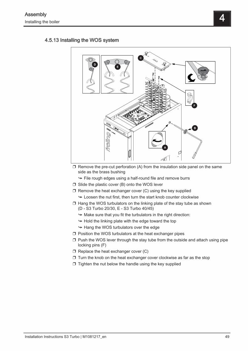
4.5.13 Installing the WOS system
❒ Remove the pre-cut perforation (A) from the insulation side panel on the sameside as the brass bushing➥ File rough edges using a half-round file and remove burrs
❒ Slide the plastic cover (B) onto the WOS lever❒ Remove the heat exchanger cover (C) using the key supplied
➥ Loosen the nut first, then turn the start knob counter clockwise❒ Hang the WOS turbulators on the linking plate of the stay tube as shown
(D - S3 Turbo 20/30, E - S3 Turbo 40/45)➥ Make sure that you fit the turbulators in the right direction:➥ Hold the linking plate with the edge toward the top➥ Hang the WOS turbulators over the edge
❒ Position the WOS turbulators at the heat exchanger pipes❒ Push the WOS lever through the stay tube from the outside and attach using pipe
locking pins (F)❒ Replace the heat exchanger cover (C)❒ Turn the knob on the heat exchanger cover clockwise as far as the stop❒ Tighten the nut below the handle using the key supplied
Assembly 4Installing the boiler
Installation Instructions S3 Turbo | M1081217_en 49
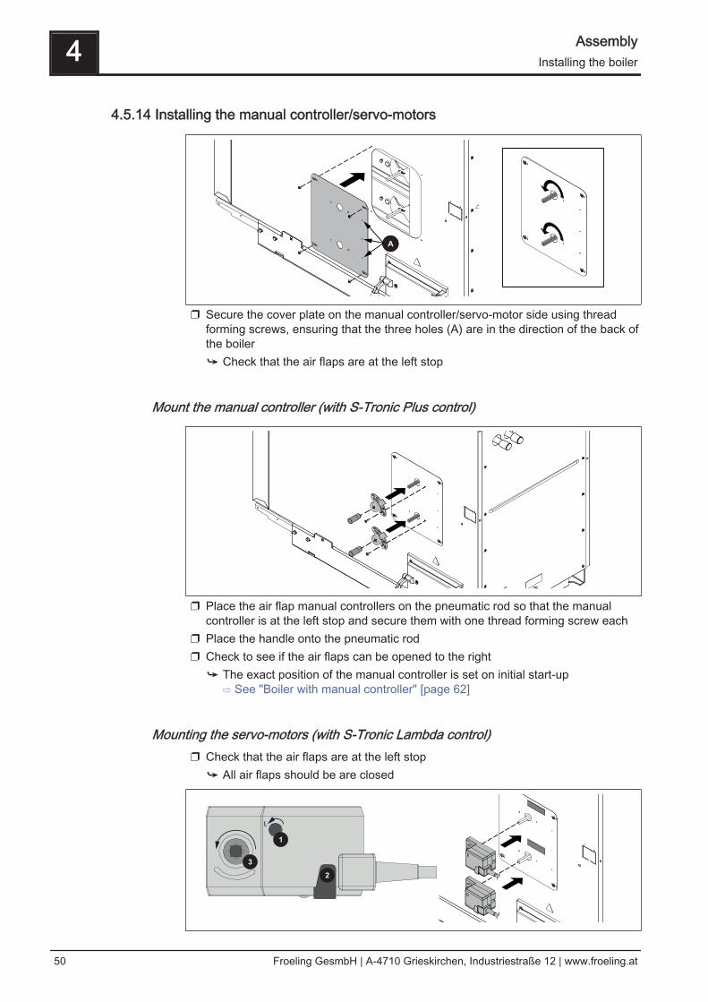
4.5.14 Installing the manual controller/servo-motors
❒ Secure the cover plate on the manual controller/servo-motor side using threadforming screws, ensuring that the three holes (A) are in the direction of the back ofthe boiler➥ Check that the air flaps are at the left stop
Mount the manual controller (with S-Tronic Plus control)
❒ Place the air flap manual controllers on the pneumatic rod so that the manualcontroller is at the left stop and secure them with one thread forming screw each
❒ Place the handle onto the pneumatic rod❒ Check to see if the air flaps can be opened to the right
➥ The exact position of the manual controller is set on initial start-up ⇨ See "Boiler with manual controller" [page 62]
Mounting the servo-motors (with S-Tronic Lambda control)❒ Check that the air flaps are at the left stop
➥ All air flaps should be are closed
L
4 AssemblyInstalling the boiler
50 Froeling GesmbH | A-4710 Grieskirchen, Industriestraße 12 | www.froeling.at
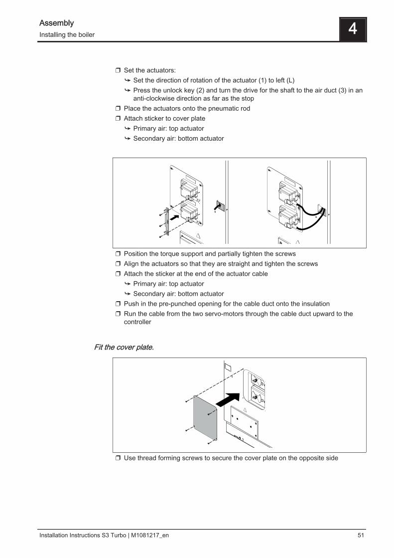
❒ Set the actuators:
➥ Set the direction of rotation of the actuator (1) to left (L)➥ Press the unlock key (2) and turn the drive for the shaft to the air duct (3) in an
anti-clockwise direction as far as the stop❒ Place the actuators onto the pneumatic rod❒ Attach sticker to cover plate
➥ Primary air: top actuator➥ Secondary air: bottom actuator
❒ Position the torque support and partially tighten the screws❒ Align the actuators so that they are straight and tighten the screws❒ Attach the sticker at the end of the actuator cable
➥ Primary air: top actuator➥ Secondary air: bottom actuator
❒ Push in the pre-punched opening for the cable duct onto the insulation❒ Run the cable from the two servo-motors through the cable duct upward to the
controller
Fit the cover plate.
❒ Use thread forming screws to secure the cover plate on the opposite side
Assembly 4Installing the boiler
Installation Instructions S3 Turbo | M1081217_en 51
4.6 Power connection and wiring
DANGER
When working on electrical components:
Risk of electrocution!
When work is carried out on electrical components:❒ Only have work carried out by a qualified electrician❒ Observe the applicable standards and regulations
➥ Work must not be carried out on electrical components by unauthorisedpersons
4.6.1 S-Tronic Plus / S-Tronic Lambda control
Power connection❒ Run the cable of the flue gas temperature sensor, boiler sensor, induced draught,
STL, display and door switch to the controller and connect the wiring inaccordance with the operating instructions of the boiler control➥ Tuck any extra cable into the cable duct
❒ Run the cable of the broadband probe, servo-motors, flue gas temperature sensor,
boiler sensor, induced draught, STL, display and door switch to the controller andconnect the wiring in accordance with the operating instructions of the boilercontrol➥ Tuck any extra cable into the cable duct
❒ Connect the components according to the power connection diagram
➥ The flexible sheathed cable must be used for the wiring; this must be of thecorrect size to comply with applicable regional standards and regulations!
Once the individual components have been wired:❒ Wire the mains connection in the controller box
➥ The power supply line (mains connection) must be fitted with a max. C13A fuseby the customer!
➥ Observe the circuit diagrams in the boiler controller operating instructions.
S-Tronic Plus:
S-Tronic Lambda:
4 AssemblyPower connection and wiring
52 Froeling GesmbH | A-4710 Grieskirchen, Industriestraße 12 | www.froeling.at
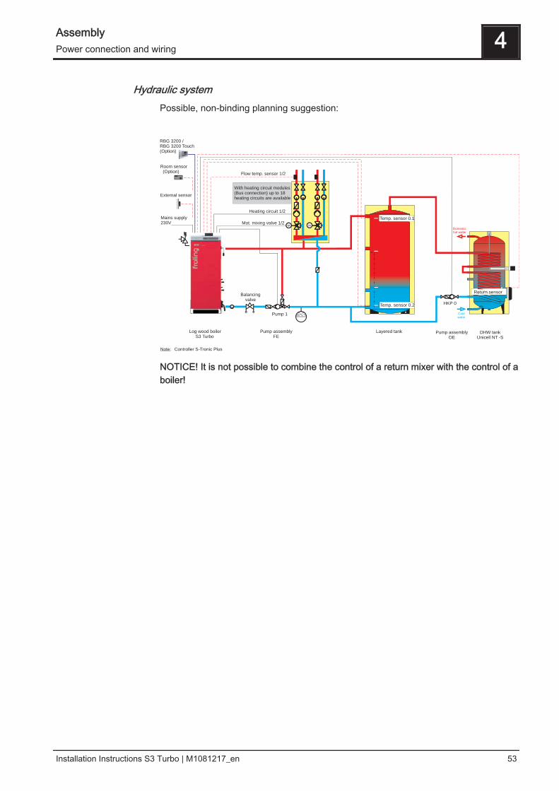
Hydraulic systemPossible, non-binding planning suggestion:
MM MM
Room sensor(Option)
External sensor
Mains supply230V
Log wood boilerS3 Turbo
Pump assemblyFE
Pump 1
Flow temp. sensor 1/2
Heating circuit 1/2
Mot. mixing valve 1/2
Layered tank
Domestichot water
HKP 0
Coldwater
Pump assemblyOE
DHW tankUnicell NT -S
Note: Controller S-Tronic Plus
Temp. sensor 0.1
Temp. sensor 0.2
Return sensor
With heating circuit modules(Bus connection) up toheating circuits are available
18
RBG 3200 /RBG 3200 Touch(Option)
Balancingvalve
NOTICE! It is not possible to combine the control of a return mixer with the control of aboiler!
Assembly 4Power connection and wiring
Installation Instructions S3 Turbo | M1081217_en 53
4.6.2 Information on circulating pumps
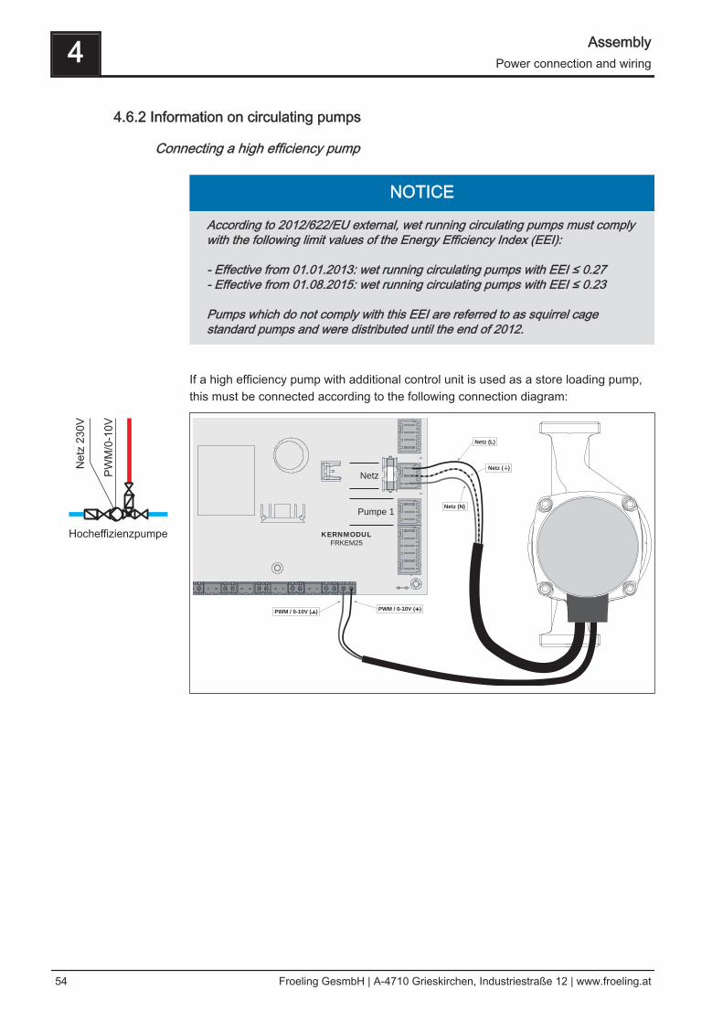
Connecting a high efficiency pump
NOTICE
According to 2012/622/EU external, wet running circulating pumps must complywith the following limit values of the Energy Efficiency Index (EEI):
- Effective from 01.01.2013: wet running circulating pumps with EEI ≤ 0.27- Effective from 01.08.2015: wet running circulating pumps with EEI ≤ 0.23
Pumps which do not comply with this EEI are referred to as squirrel cagestandard pumps and were distributed until the end of 2012.
If a high efficiency pump with additional control unit is used as a store loading pump,this must be connected according to the following connection diagram:
KERNMODUL
FRKEM25
PWM / 0-10V (+)PWM / 0-10V ( )
Netz (L)
Netz ( )
Netz (N)
Pumpe 1
Netz
4 AssemblyPower connection and wiring
54 Froeling GesmbH | A-4710 Grieskirchen, Industriestraße 12 | www.froeling.at
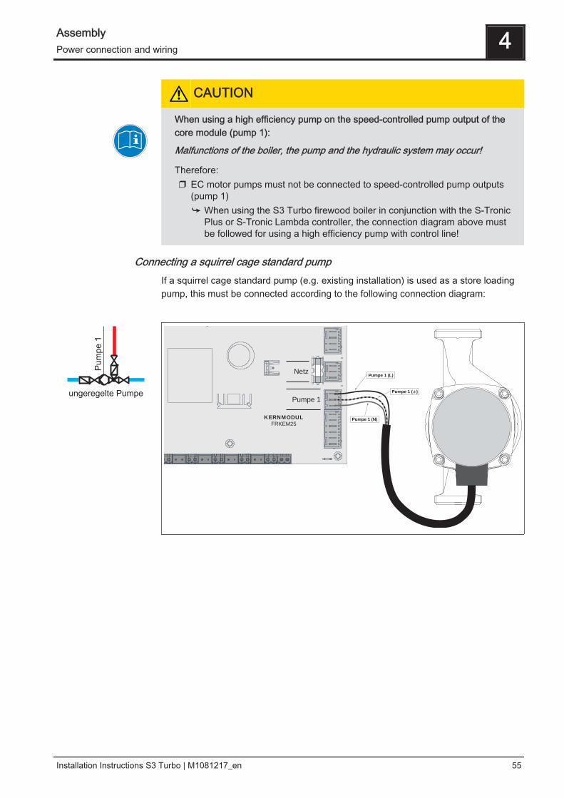
CAUTION
When using a high efficiency pump on the speed-controlled pump output of thecore module (pump 1):
Malfunctions of the boiler, the pump and the hydraulic system may occur!
Therefore:❒ EC motor pumps must not be connected to speed-controlled pump outputs
(pump 1)➥ When using the S3 Turbo firewood boiler in conjunction with the S-Tronic
Plus or S-Tronic Lambda controller, the connection diagram above mustbe followed for using a high efficiency pump with control line!
Connecting a squirrel cage standard pumpIf a squirrel cage standard pump (e.g. existing installation) is used as a store loadingpump, this must be connected according to the following connection diagram:
KERNMODUL
FRKEM25
Pumpe 1 (L)
Pumpe 1 ( )
Pumpe 1 (N)
Pumpe 1
Netz
Assembly 4Power connection and wiring
Installation Instructions S3 Turbo | M1081217_en 55
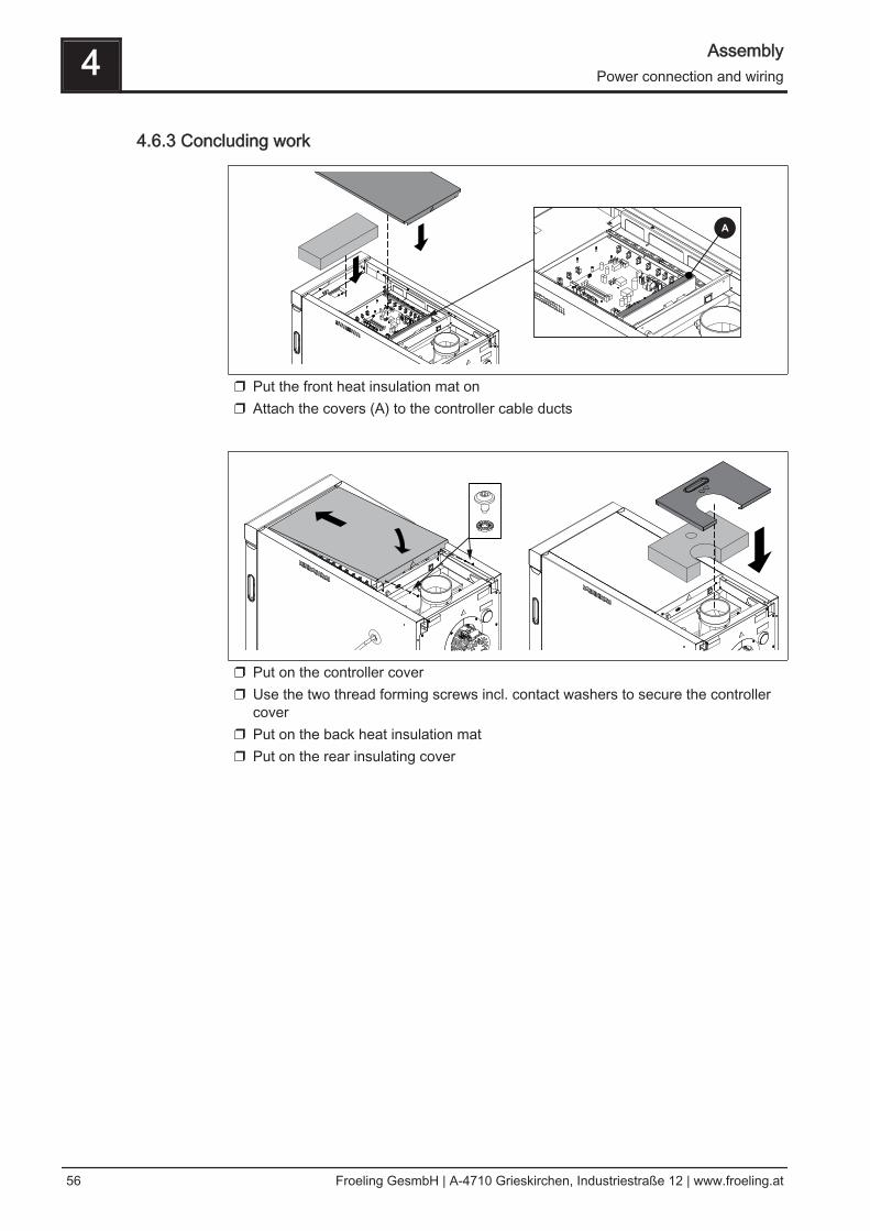
4.6.3 Concluding work
❒ Put the front heat insulation mat on❒ Attach the covers (A) to the controller cable ducts
❒ Put on the controller cover❒ Use the two thread forming screws incl. contact washers to secure the controller
cover❒ Put on the back heat insulation mat❒ Put on the rear insulating cover
4 AssemblyPower connection and wiring
56 Froeling GesmbH | A-4710 Grieskirchen, Industriestraße 12 | www.froeling.at
4.7 Connecting the hydraulic safety devices
1.1
2
34
1.2
1.3
1.5
1.4
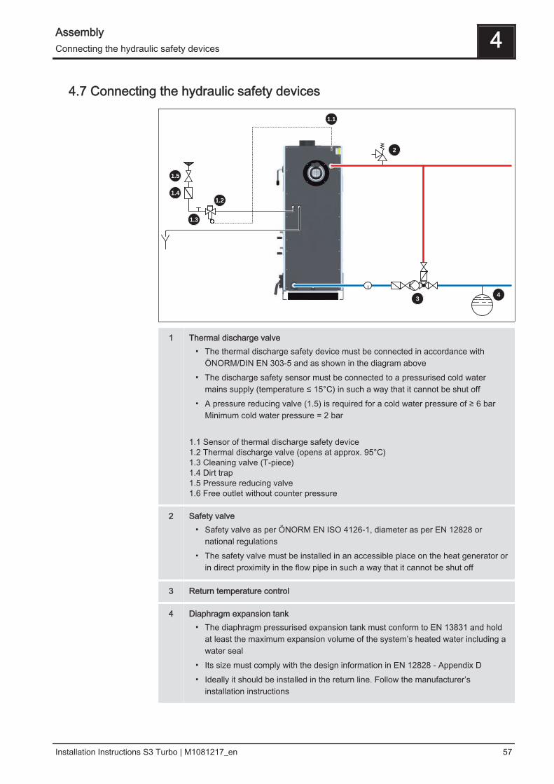
1 Thermal discharge valve▪ The thermal discharge safety device must be connected in accordance with
ÖNORM/DIN EN 303-5 and as shown in the diagram above▪ The discharge safety sensor must be connected to a pressurised cold water
mains supply (temperature ≤ 15°C) in such a way that it cannot be shut off▪ A pressure reducing valve (1.5) is required for a cold water pressure of ≥ 6 bar
Minimum cold water pressure = 2 bar 1.1 Sensor of thermal discharge safety device 1.2 Thermal discharge valve (opens at approx. 95°C)1.3 Cleaning valve (T-piece)1.4 Dirt trap1.5 Pressure reducing valve1.6 Free outlet without counter pressure
2 Safety valve▪ Safety valve as per ÖNORM EN ISO 4126-1, diameter as per EN 12828 or
national regulations▪ The safety valve must be installed in an accessible place on the heat generator or
in direct proximity in the flow pipe in such a way that it cannot be shut off
3 Return temperature control
4 Diaphragm expansion tank▪ The diaphragm pressurised expansion tank must conform to EN 13831 and hold
at least the maximum expansion volume of the system’s heated water including awater seal
▪ Its size must comply with the design information in EN 12828 - Appendix D▪ Ideally it should be installed in the return line. Follow the manufacturer’s
installation instructions
Assembly 4Connecting the hydraulic safety devices
Installation Instructions S3 Turbo | M1081217_en 57
5 Start-up
5.1 Before commissioning / configuring the boilerThe boiler must be configured to the heating system on initial start-up.
NOTICE
Optimum efficiency and efficient, low-emission operation can only be guaranteedif the system is set up by trained professionals and the standard factory settingsare observed.
Take the following precautions:❒ Initial startup should be carried out with an authorised installer or with Froling
customer services
NOTICE
Foreign bodies in the heating system impair its operational safety and can resultin damage to property.
As a result:❒ The whole system should be rinsed out before initial start-up in accordance
with EN 14336.❒ Recommendation: Make sure the hose diameter of the flush nozzles in the
flow and return complies with ÖNORM H 5195 and is the same as the hosediameter in the heating system, however not more than DN 50.
❒ Turn on the main switch❒ Set the boiler controller to the system type.❒ Load the boiler default values.
NOTICE! For the keypad layout and instructions for modifying the parameters, see theinstruction manual for the boiler controller.❒ Check the system pressure of the heating system.❒ Check that the heating system is fully vented.❒ Check that all water connections are tightly sealed
➥ Pay particular attention to those connections from which plugs were removedduring assembly.
❒ Check that the safety devices are present and working efficiently.❒ Check that there is sufficient ventilation in the boiler room.❒ Check the seal of the boiler.
➥ All doors and inspection openings must be tightly sealed.❒ Check that the drives and servo motors are working and turning in the right
direction.❒ Check that the door contact switch is working efficiently.
NOTICE! Check the digital and analog inputs and outputs - See the instruction manualfor the boiler controller.
5 Start-upBefore commissioning / configuring the boiler
58 Froeling GesmbH | A-4710 Grieskirchen, Industriestraße 12 | www.froeling.at
5.2 Initial startup
5.2.1 Permitted fuels
FirewoodFirewood up to max. 55 cm long.
Water content (w) greater than 15% (equivalent to wood moisture u > 17%)Water content (w) less than 25% (equivalent to wood moisture u < 33%)
EU: Fuel as per EN ISO 17225 – Part 5: Firewood class A2 / D15 L50
Additional forGermany: Fuel class 4 (§3 of the First Federal Emissions Protection Ordinance
(BimSchV) in the last amended version)
▪ Use wind-exposed areas where possible for storage (e.g. store at edge of forest insteadof in forest)
▪ Walls of buildings facing the sun are ideal▪ Create a dry underlay, where possible with air access (line with round timber, pallets,
etc.)▪ stack split wood and store in such a way that it is protected from the elements▪ If possible, stock fuel for the day in a warm place (e.g. in boiler room) (pre-heats the
fuel!)
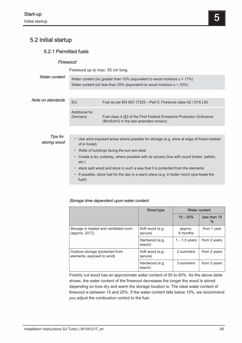
Storage time dependent upon water content
Wood type Water content
15 – 25% less than 15%
Storage in heated and ventilated room(approx. 20°C)
Soft wood (e.g.spruce)
approx.6 months
from 1 year
Hardwood (e.g.beech)
1 – 1.5 years from 2 years
Outdoor storage (protected fromelements, exposed to wind)
Soft wood (e.g.spruce)
2 summers from 2 years
Hardwood (e.g.beech)
3 summers from 3 years
Freshly cut wood has an approximate water content of 50 to 60%. As the above tableshows, the water content of the firewood decreases the longer the wood is storeddepending on how dry and warm the storage location is. The ideal water content offirewood is between 15 and 25%. If the water content falls below 15%, we recommendyou adjust the combustion control to the fuel.
Water content
Note on standards
Tips for storing wood
Start-up 5Initial startup
Installation Instructions S3 Turbo | M1081217_en 59
5.2.2 Fuels permitted under certain conditions
Wood briquettesWood briquettes for non-industrial use with a diameter of 5-10 cm and 5-50 cm long.
EU: Fuel as per EN ISO 17225 - Part 3:wood briquettes class B / D100 L500 Form 1 - 3
Additional forGermany: Fuel class 5a (§3 of the First Federal Emissions Protection Ordinance
(BImSchV) - applicable version)
▪ When burning wood briquettes use the settings for extremely dry fuel▪ Wood briquettes must be heated up with firewood as per EN ISO 17225-5
(at least two layers of firewood under the wood briquettes)▪ The fuel loading chamber must not be filled more than 3/4 full, as the wood briquettes
expand during combustion▪ Even when using the settings for dry fuel, burning wood briquettes can cause
combustion problems. In such cases, repairs must be carried out by qualified staff.Please contact Froling customer services or your installer.
5.2.3 Non-permitted fuelsThe use of fuels not defined in the "Permitted fuels" section, and particularly theburning of refuse, is not permitted.
CAUTION
In case of use of non-permitted fuels:
Burning non-permitted fuels increases the cleaning requirements and leads to abuild-up of aggressive sedimentation and condensation, which can damage theboiler and also invalidates the guarantee. Using non-standard fuels can also leadto serious problems with combustion.
For this reason, when operating the boiler:❒ Only use permitted fuels
Note on standards
Notes on use
5 Start-upInitial startup
60 Froeling GesmbH | A-4710 Grieskirchen, Industriestraße 12 | www.froeling.at
5.2.4 Heating up for the first time
CAUTION
If the boiler heats up too quickly on initial start-up:
If the output during the heating-up process is too great, the combustion chambermay be damaged as a result of drying out too rapidly!
For this reason the following applies the first time you heat up the boiler:❒ Start the firewood boiler for the first time in accordance with the heating
instructions
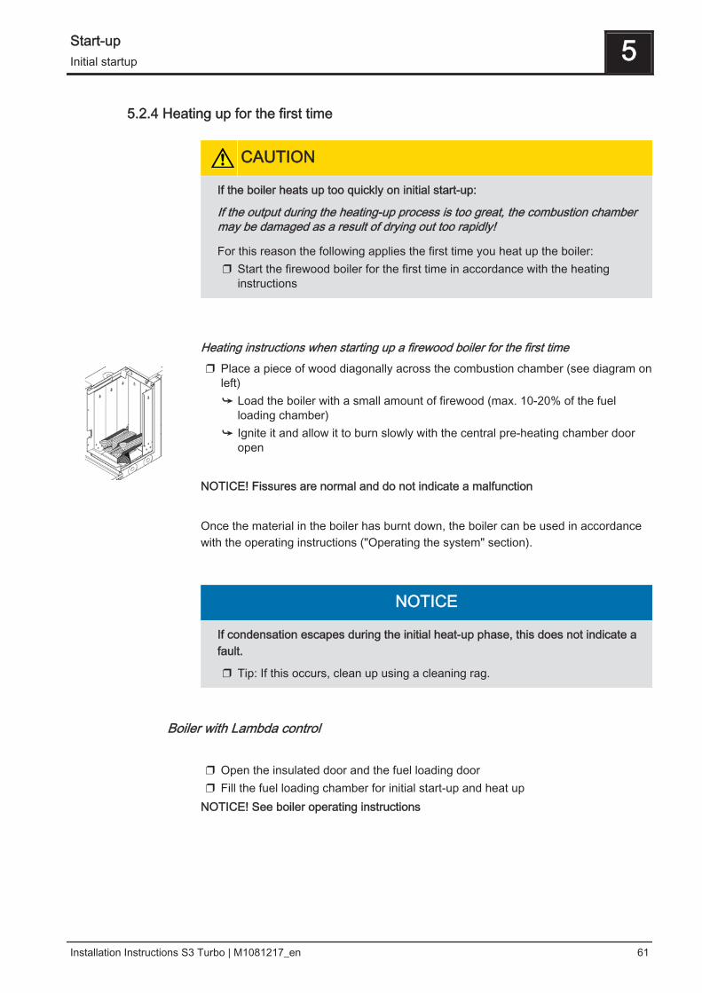
Heating instructions when starting up a firewood boiler for the first time❒ Place a piece of wood diagonally across the combustion chamber (see diagram on
left)➥ Load the boiler with a small amount of firewood (max. 10-20% of the fuel
loading chamber)➥ Ignite it and allow it to burn slowly with the central pre-heating chamber door
open NOTICE! Fissures are normal and do not indicate a malfunction Once the material in the boiler has burnt down, the boiler can be used in accordancewith the operating instructions ("Operating the system" section).
NOTICE
If condensation escapes during the initial heat-up phase, this does not indicate afault.
❒ Tip: If this occurs, clean up using a cleaning rag.
Boiler with Lambda control ❒ Open the insulated door and the fuel loading door❒ Fill the fuel loading chamber for initial start-up and heat up
NOTICE! See boiler operating instructions
Start-up 5Initial startup
Installation Instructions S3 Turbo | M1081217_en 61
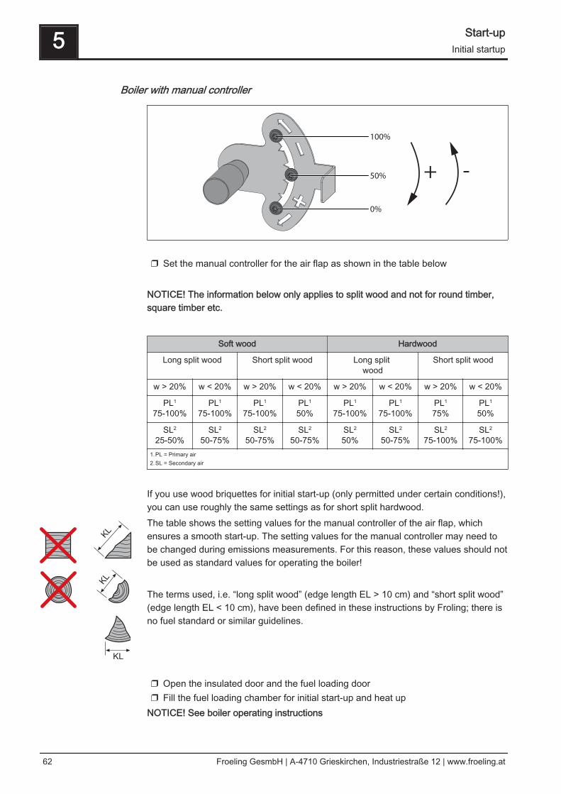
Boiler with manual controller
100%
50%
0%
+ -
❒ Set the manual controller for the air flap as shown in the table below
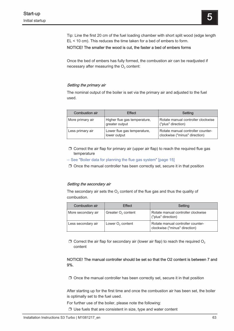
NOTICE! The information below only applies to split wood and not for round timber,square timber etc.
Soft wood Hardwood
Long split wood Short split wood Long split wood
Short split wood
w > 20% w < 20% w > 20% w < 20% w > 20% w < 20% w > 20% w < 20%
PL1
75-100%PL1
75-100%PL1
75-100%PL1
50%PL1
75-100%PL1
75-100%PL1
75%PL1
50%
SL2
25-50%SL2
50-75%SL2
50-75%SL2
50-75%SL2
50%SL2
50-75%SL2
75-100%SL2
75-100%1.PL = Primary air2.SL = Secondary air
If you use wood briquettes for initial start-up (only permitted under certain conditions!),you can use roughly the same settings as for short split hardwood.The table shows the setting values for the manual controller of the air flap, whichensures a smooth start-up. The setting values for the manual controller may need tobe changed during emissions measurements. For this reason, these values should notbe used as standard values for operating the boiler! The terms used, i.e. “long split wood” (edge length EL > 10 cm) and “short split wood”(edge length EL < 10 cm), have been defined in these instructions by Froling; there isno fuel standard or similar guidelines. ❒ Open the insulated door and the fuel loading door❒ Fill the fuel loading chamber for initial start-up and heat up
NOTICE! See boiler operating instructions
5 Start-upInitial startup
62 Froeling GesmbH | A-4710 Grieskirchen, Industriestraße 12 | www.froeling.at
Tip: Line the first 20 cm of the fuel loading chamber with short split wood (edge lengthEL < 10 cm). This reduces the time taken for a bed of embers to form.NOTICE! The smaller the wood is cut, the faster a bed of embers forms Once the bed of embers has fully formed, the combustion air can be readjusted ifnecessary after measuring the O2 content:
Setting the primary air
The nominal output of the boiler is set via the primary air and adjusted to the fuelused.
Combustion air Effect Setting
More primary air Higher flue gas temperature, greater output
Rotate manual controller clockwise("plus" direction)
Less primary air Lower flue gas temperature, lower output
Rotate manual controller counter-clockwise ("minus" direction)
❒ Correct the air flap for primary air (upper air flap) to reach the required flue gas
temperature⇨ See "Boiler data for planning the flue gas system" [page 15]❒ Once the manual controller has been correctly set, secure it in that position
Setting the secondary air
The secondary air sets the O2 content of the flue gas and thus the quality ofcombustion.
Combustion air Effect Setting
More secondary air Greater O2 content Rotate manual controller clockwise("plus" direction)
Less secondary air Lower O2 content Rotate manual controller counter-clockwise ("minus" direction)
❒ Correct the air flap for secondary air (lower air flap) to reach the required O2
content NOTICE! The manual controller should be set so that the O2 content is between 7 and9%. ❒ Once the manual controller has been correctly set, secure it in that position
After starting up for the first time and once the combustion air has been set, the boileris optimally set to the fuel used.For further use of the boiler, please note the following:❒ Use fuels that are consistent in size, type and water content
Start-up 5Initial startup
Installation Instructions S3 Turbo | M1081217_en 63

❒ If a very different type of fuel is used, get a qualified technician to check the airflap setting and adjust if necessary
5 Start-upInitial startup
64 Froeling GesmbH | A-4710 Grieskirchen, Industriestraße 12 | www.froeling.at
6 Decommissioning
6.1 MothballingThe following measures should be taken if the boiler is to remain out of service forseveral weeks (e.g. during the summer):❒ Clean the boiler thoroughly and close the doors fully
If the boiler is to remain out of service during the winter:❒ Have the system completely drained by a qualified technician
➥ Protection against frost
6.2 DisassemblyTo disassemble the system, follow the steps for assembly in reverse order.
6.3 Disposal❒ Ensure that they are disposed of in an environmentally friendly way in accordance
with waste management regulations in the country (e.g. AWG in Austria)❒ You can separate and clean recyclable materials and send them to a recycling
centre.❒ The combustion chamber must be disposed of as builders' waste.
Decommissioning 6Mothballing
Installation Instructions S3 Turbo | M1081217_en 65
7 Appendix
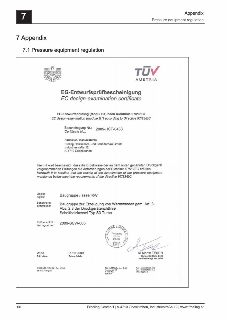
7.1 Pressure equipment regulation
7 AppendixPressure equipment regulation
66 Froeling GesmbH | A-4710 Grieskirchen, Industriestraße 12 | www.froeling.at
7.2 Addresses
7.2.1 Address of manufacturer
FRÖLINGHeizkessel- und Behälterbau GesmbH Industriestraße 12A-4710 GrieskirchenAUSTRIA TEL 0043 (0)7248 606 0FAX 0043 (0)7248 606 600INTERNET www.froeling.com
7.2.2 Address of the installer
Stamp
Appendix 7Addresses
Installation Instructions S3 Turbo | M1081217_en 67