Embed Size (px)
Citation preview

Fire wood processor VM420 Instruction manual
Duun Industrier as7630 Åsen, Norwaywww.duun.no

Congratulations with your Duun VM420 firewood processor.
All Duun tractor operated machines has been engineered and tested in close cooperation with end users of our products. This in order to develop reliable and user friendly machines
Please red instructions manual before you start using the machines..
B A
Machine identificationSerial number and manufacturer should be indicated at badge (A)Register serial No and time of delivery as indicated.Do always specify serial number every time requesting service for the machine.The machine has a CE-badge (B) this confirms that the machine has been manufactured in conformity with: Directive 98/37/EC Mechanical equipment Article 8 Annex 4 and 5
Serial number
Time of delivery (month-year)
2

List of content
MACHINE IDENTIFICATION ............................................................................................................................. 2
WARRANTY TERMS ......................................................................................................................................... 9
DELIVERY FORM FOR DUUN VM420 FIREWOOD PROCESSOR ................................................................ 10
SPECIFICATIONS ............................................................................................................................................ 11
......................................................................................................................................................................... 12
PREPARATIONS BEFORE USE ..................................................................................................................... 13
TRANSPORT AND HANDLING BEFORE USE ......................................................................................................................... 13 PREPARATION FOR MOVING WITH TRACTOR. .................................................................................................................... 13 SECURING BEFORE MOVING ......................................................................................................................................... 13 HYDRAULIC OIL - QUALITY. .......................................................................................................................................... 14 OIL LEVEL CHECK. ..................................................................................................................................................... 14 OIL TEMPERATURE CHECK ........................................................................................................................................... 14 CONDENSE CHECK .................................................................................................................................................... 15 DRIVE SHAFT ........................................................................................................................................................... 15 PREPARATION OF THE TRANSPORTER. ........................................................................................................................... 16 PREPARATION OF THE FEEDING CONVEYOR ...................................................................................................................... 16 SETTING OF CUTTING LENGTH ...................................................................................................................................... 16 SETTING OF SPLITTING LENGTH FROM 60 TO 40CM ........................................................................................................... 17 SETTING OF SPLITTING LENGTH FROM 40 TO 60CM ........................................................................................................... 17 HEIGHT ADJUSTMENT OF THE MACHINE ........................................................................................................................... 18
PRACTICAL USE ............................................................................................................................................. 18
CONDITION .............................................................................................................................................................. 18 START-UP AND SUITABLE ROTATING SPEED – 500 – 540 RPM ............................................................................................ 18 MAIN FUNCTIONS – FEEDING – SPEED ADJUSTMENT OF THE FEEDING CONVEYOR ...................................................................... 19 ADJUSTMENT OF CUTTING ........................................................................................................................................... 19 SPEED OUTPUT CONVEYOR .......................................................................................................................................... 19 HYDRAULIC KNIFE LIFT ................................................................................................................................................ 20 CUTTING ................................................................................................................................................................. 20 SAFETY HAND OPERATED LOG HOLDER ........................................................................................................................... 20 SIDEWAYS ADJUSTMENT OF THE TRANSPORTER ................................................................................................................. 21 JAMMED WOOD MATERIALS .......................................................................................................................................... 21
CHAIN SHARPENING ..................................................................................................................................... 22
CHAIN TENSIONING AND ADJUSTMENT OF THE CHAIN LUBRICATION ................................................. 24
SERVICE AND MAINTENANCE ...................................................................................................................... 25
EVERYDAY MAINTENANCE INSPECTION ............................................................................................................................ 25 WEEKLY MAINTENANCE ............................................................................................................................................... 27 LUBRICATION POINTS .................................................................................................................................................. 28 MONTHLY MAINTENANCE ............................................................................................................................................. 29 YEARLY MAINTENANCE ................................................................................................................................................ 29
DECLARATION OF CONFORMITY ................................................................................................................. 30
3

SAFETYAll operators, mechanics and the owner must be well acquainted with the instruction in this instruction manual before the machine is taken into use.You should always work with care when you employ agricultural machinery. Read and observe the safety instructions in this binder. Your safety is your responsibility!
Be particularly aware of warning signs with this symbol it marks measures that must be carried out in order to avoid accidents. The symbol appears in the instruction manual and on warning signs on the machine.
Instruction manualAll operators, mechanics and the owner must be well acquainted with the instruction in this instruction manual before the machine is taken into use.
The safety of the surroundingsMake sure that no-one not concerned are present in the area of work. We emphasize as strongly as possible that only one person is to handle the machine, i.e. operate the saw chain sword and the splitter. Nobody is to assist the main operator in the work area - risk of injury! Never start the machine when there are people or animals close to the machine or the tractor. Never stand between the tractor wheels and the machine! If other persons than the operator of the machine are present in the risk zone, the operator is to explain the danger the machine involves!
Personal protection equipmentYou should always wear hearing protection and protective goggles when using the wood machine. Further, you should use protective footwear and sturdy work gloves during handling of the machine and the materials.
4

Clothing and the drive shaftDo not work in clothing that may be caught in the moving parts of the machine (for example scarf, wide coats).The tractor must be disconnected and the hand brake activated before the shaft is connected to the tractor’s power take-off. The drive shafts are always to be equipped with original protection covers.Damaged and worn covers are to be replaced immediately!Make sure that all covers for the shaft are in good condition and correctly fitted. Never start the machine when this is not in order. The locking chains for the plastic covers are always to be fixed to the appropriate brackets in order to prevent the covers to rotate.
Safe connection and use.Allow nobody to stay between the machine and tractor when the machine is connected to the tractor. The same applies during use of the machine. Make sure that the connection is carried out in a safe manner.
6. Safety in case of interruptions and maintenance. Remember always to stop the tractor’s engine and remove the ignition key before you lubricate, adjust, clean or carry out repairs. This is to secure that the tractor does not start before you have completed the operation..
Hydraulic high fluid pressure. Be careful when you work with hydraulics. Wear eye protection and gloves. Hydraulic oil under great pressure may penetrate the skin and cause serious infections. See a doctor is you have had had an injury. Ensure that no-one is standing close by when hydraulic functions are performed.
5

Rotating parts – risk of crushing The machine’s rotating parts may cause severe injuries. The same applies to risk of crushing during operation.All covers and protective equipment is to be fitted on the machine during use. The user is responsible if an accident occurs as a consequence of defective protection. Avoid all unnecessary stay in the working area when the machine is in operation.Never put your hand in behind the protective screen even if the saw chain is in back position..
Zero alcohol tolerance Persons who are under the influence of drink or drugs must not operate the machine. The same applies to tired people who do not have full control over their movements.
Contact with electric wires and similar during transport.Be aware that the wood machine may be taller than the tractor during transport and there is a risk of contact with electric wires, railroad underpasses etc!If the machine has been set up for splitting of 60cm wood lengths, it should be set back to 40cm before moving. This is because the machine will protrude on the right side if it transported in "60cm set-up". If you choose to move the machine in “60cm set-up”, you should be very attentive of the fact that there is a protrusion beyond the width of the tractor on the right hand side.
Conveyor – conveyor beltAvoid staying under the transporter when this is under tension in order to avoid injuries in case of any uncontrolled downfall during use. Also avoid contact with the transporter’s moving parts during use..
6

Horizontal positioning and tidiness on the workplace Always place the machine as horizontally and steady as possible to secure stable working conditions.Keep the workplace as tidy as possible. This contributes to generally better safety against unwanted events.
Area of application The machines are only intended for production of fire wood from “pure” wood material without any contaminants. It is not allowed to employ the machine for other material such as construction waste and similar with metal parts such as nails, screws and similar. The same applies for materials that are polluted with plaster and similar coatings. The saw chain is only designed for wood materials without contaminants.
Good lighting – a necessity.The machine must only be used in daylight that secures a good overview of the operations – or with artificial lighting which provides good overview of the work area.Good lighting is very important with reference to safety.
Safe transport Before the machine is moved, the feeder conveyor and transporter (both in an up-right position as outlined in the illustration) are to be strapped to secure that they do not fall down. The loading strap has a fixing point at the lower part of the feeding conveyor and secures the conveyor belt from falling off during transport.
7

17. Safe cuttingAvoid placing your hands close to the saw chain. This is obtained by consequently using the log holder A and the handle B to operate it. For cutting the last log of wood, it is important to retain a “suitable” length and cut a shorter piece as the next to last.. You are advised to use the “count-down ruler” for the last three lengths so that these may be cut to a somewhat shorter even length than the desired length. When you want to cut twiggy or crooked logs, it is important to make sure that these are securely placed. .
Before start-up after maintenance you should check that all tools have been removed and brought back into place.
Before the machine is elevated or lowered, you should check that no-one is close to or touch the machine.
If any warning signs are removed during repair or service, new signs must be fitted immediately!
8

Warranty termsFire wood processor VM420 has a 12 month guarantee against defects in materials and workmanship.
Parts that are not originally manufactured by Duun Industrier AS, for example shafts, bearings etc. are subject to these suppliers’ guarantees and terms.
Parts that are considered to be wear parts are not part of the basis of the guarantee - these have been specified in a separate survey on the bottom part of this page.
In cases where a repair is considered to be covered by the guarantee, the representative must inform the supplier’s representatives that the repair is intended executed on the basis of the guarantee.
In this context, the following information must be recorded:• Product name• The product’s serial no. (see the machine identification pp. 6 and 7]• Date of sale• The product owner’s telephone no.• Dealer with address, telephone no.
In case of such a repair, the supplier is presented with a claim within 3 weeks after the repair date.
Replaced parts are to be kept until a decision has been made with reference to the claim and the replaced parts are to be forwarded to Duun Industrier for assessment if so required.
As the employment of the product is beyond our control, we may only guarantee the quality and do not accept liability for the product's general performance.
The guarantee liability assumes that the prescribed maintenance has been carried out.
Duun Industrier reserves the right to modify the design and specifications and/or make alterations and improvements without notification.
What is not included by the guarantee
• The guarantee does not cover economic loss as a consequence of interruptions.• The guarantee does not cover consequential loss due to defects.• The guarantee does not cover defects or damage caused by misuse and use that is not in
accordance with the instruction manual’s specifications and guidelines.The following parts and material are considered as wearing parts and are not covered by the guarantee:.
• The chain saw bar• The saw chain• The wood splitter knives• The feeding belt• Oil filter• Hydraulic oil• Filter cartridge for hydraulic oil• Wear parts in splitting mechanism
9

Delivery form for Duun VM420 firewood processor
Machine specifications
Model _ _ _ _ _ _ _ _ _ _ _
Serial No.. _ _ _ _ _ _ _ _ _ _ _
Customer details
Machine owner _ _ _ _ _ _ _ _ _ _
Address _ _ _ _ _ _ _ _ _
Aip code. _ _ _ _
Town _ _ _ _ _ _ _ _ _
Hand over of machine
Sales representative and customer have controlled that the machine do not have any transportation damages and that specified equipment is delivered..
The customer has been instructed how to use the machine:- How to prepare machine for use from transport position. - Height adjustment of machine and correct length of pto to reduce strain - from too steep angle between tractor and processor (page 14 and 18)- How to control temperature and oil level. (page 13)- How to control eventual condensation level in oil tank (page 14)- What is correct pto speed . (page 17)- The machine functions.
Feed belt: Speed adjustment . (page 18) Use of ”remote” controlCutting : Adjustment of saw movement speed and power (page 18)
Sharpening and tightening of chain. (page 21-23) Adjustment of chain greasing (page 23) How to use log clamp. (page 19)
Splitting: How to use handle for forced return . (page 20) Elevation of splitting knives and change og splitting knives (page 19) How to switch from 40 to 60cm splitting length and vice versa. (page 16)
Conveyor: Speed adjustment . (page 18) Sideward movement of conveyor. (page 20)
Sales representative and customer have read about service and maintenance (page 24-28).
The customer has been introduced to warranty terms (page 8)
The customer has been introduced to conditions for practical use (page 17)
Part list is available at sale representative.
Place _ _ _ _ _ _ _
Date _ _ _ _ _ _ _
Customers signature Sales representatives signature
_ _ _ _ _ _ _ _ _ _ _ _ _ _ _ _ _ _ _ _ _
10

Specifications
Feature VM420
Net weight 875 kgLength feeding belt A 2200 mm Length output conveyor-transporter B 4000 mmSideways transporter + total 25 degrees to each sideNumber of positions for transporter D 5 pcsTotal width during transport 2.550 mmHeight to work table max min F 880-960 mm Total width assembled 30 degrees trans 6.850 mmDepth seen from the side 1.280 mmVelocity drive shaft 540 rpm Connection with bolt fittings are standard YesTotal height ready for transport E 2,550 mmDiameter ventilation fan 254 mmRequired power PTO 540 rpm max 31 kWNumber of oil pumps 3Length of stroke wood splitting function 40 or 60 cmMax cutting diameter logs 42 cmSpeed splitting cycle 40 cm wood About 2 seconds at 8.5 tonsSplitting force max speed 5.5 tonsSplitting force at power drive (max power) 8.5 (11.0 tons)Connection and de-connection of power drive
Automatic
Drive of saw chain HydraulicDrive of input and output conveyor HydraulicSaw chain lubrication capacity container 5 litresSaw chain lubrication Separate pump adjustableOil tank volume 78 litres Splitting knife 6-splitter is standardHydraulic pressure 220 bar max
splitting force180 bar cutting circuit
Accessories Art. No.4-splitter knife 141200048-splitter knife 14120003Power shaft Weasler L=860 4 piece 2962156Remote control of input conveyor 141209020
All specifications are approximate values.
11

F
C
E
D
DA
B
12

Preparations before use
A
Transport and handling before useThe VM420 body is equipped with a fork pocket (A) for handling with fork truck or pallet forks. Be aware that one individual wood machine weighs about 875 kg. Use lifting equipment designed for such total weight!
G
B
EPreparation for moving with tractor. The transporter is folded together in the joint E. Afterwards, the transporter is moved to an up-right position by means of the winch wire. During this process, the protection cover is shifted in point B Feeding table and the conveyor belt is adjusted to a vertical and horizontal position by releasing the locking pin in point G
Securing before movingFinally, the connection between the feeding table and the transporter should be secured by means of a strap for this purpose with fixing points as shown in the illustration. This is important to ensure that the feeding conveyor is kept in place during transport and the connection between the feeing table and the transporter is safely secured.
13
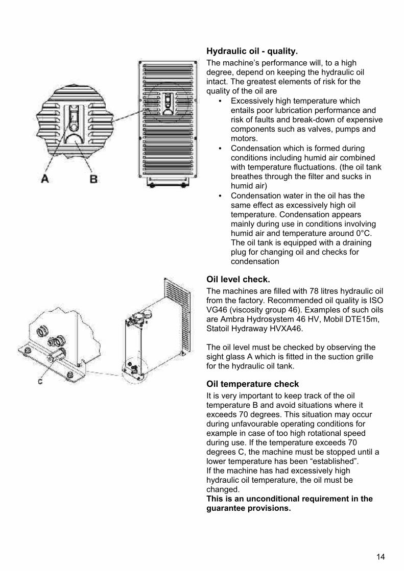
Hydraulic oil - quality.The machine’s performance will, to a high degree, depend on keeping the hydraulic oil intact. The greatest elements of risk for the quality of the oil are
• Excessively high temperature which entails poor lubrication performance and risk of faults and break-down of expensive components such as valves, pumps and motors.
• Condensation which is formed during conditions including humid air combined with temperature fluctuations. (the oil tank breathes through the filter and sucks in humid air)
• Condensation water in the oil has the same effect as excessively high oil temperature. Condensation appears mainly during use in conditions involving humid air and temperature around 0°C. The oil tank is equipped with a draining plug for changing oil and checks for condensation
Oil level check.The machines are filled with 78 litres hydraulic oil from the factory. Recommended oil quality is ISO VG46 (viscosity group 46). Examples of such oils are Ambra Hydrosystem 46 HV, Mobil DTE15m, Statoil Hydraway HVXA46.
The oil level must be checked by observing the sight glass A which is fitted in the suction grille for the hydraulic oil tank.
Oil temperature checkIt is very important to keep track of the oil temperature B and avoid situations where it exceeds 70 degrees. This situation may occur during unfavourable operating conditions for example in case of too high rotational speed during use. If the temperature exceeds 70 degrees C, the machine must be stopped until a lower temperature has been “established”. If the machine has had excessively high hydraulic oil temperature, the oil must be changed. This is an unconditional requirement in the guarantee provisions.
14

Condense checkThe oil tank is equipped with a drainage plug C in the bottom. Grey oil is an indication of water in the oil. In case the oil is polluted with water, all the hydraulic oil must be changed. Beyond such conditions, the hydraulic oil must be changed every year or after 500 operating hours (whatever occurs first).
Drive shaftThe requirement for the length of the drive shaft will vary in pace with the size of the tractor and the length of the steady-braces. If there are operating angles from 25 degrees and upwards, you should employ a category 6 shaft to ensure long service life.If there are great angles, it might be advantageous either to lower the tractor or elevating the machine. It may be elevated by means of the supporting legs which is standard equipment fitted in the corners and elevate the machine up to 80mm.Ensure that the pto shaft had sufficient length. The profile tubes in the shaft are to, after any cutting, overlap by half the tube length. Any cutting of the shaft must be executed in accordance with the instructions for such operations – the cut must be trimmed for burrs both on the inside as well on the outside and the profile tubes should be well greased. Too short telescope length of the shaft entails a risk of overload of the tractor’s power take-off and the gearbox of the VM420.Please lubricate the PTO drive shaft before use.The locking chains for the plastic covers are always to be fixed to the appropriate brackets in order to prevent the covers to rotate.The drive shaft must be maintained and used in accordance with its instruction manual.In order to obtain better operating angle, you may let the machine stand by itself and place the tractor at a distance and employ a longer drive shaft during operation.
15
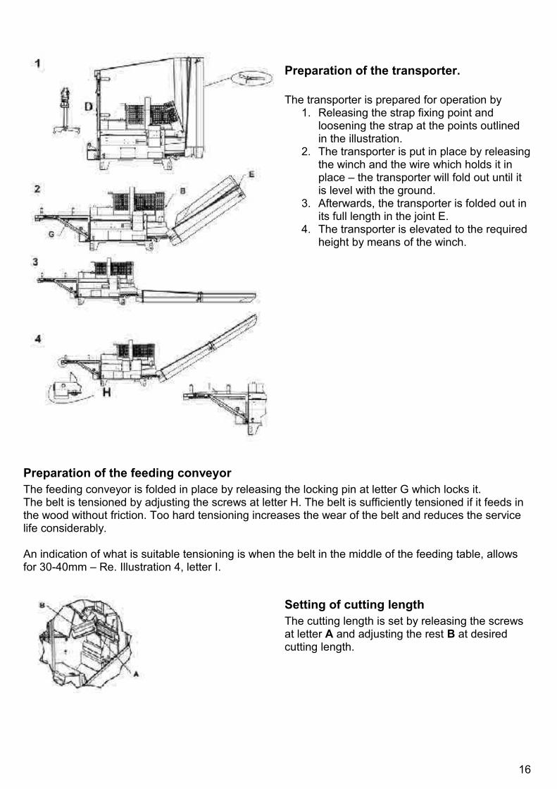
Preparation of the transporter.
The transporter is prepared for operation by1. Releasing the strap fixing point and
loosening the strap at the points outlined in the illustration.
2. The transporter is put in place by releasing the winch and the wire which holds it in place – the transporter will fold out until it is level with the ground.
3. Afterwards, the transporter is folded out in its full length in the joint E.
4. The transporter is elevated to the required height by means of the winch.
Preparation of the feeding conveyorThe feeding conveyor is folded in place by releasing the locking pin at letter G which locks it.The belt is tensioned by adjusting the screws at letter H. The belt is sufficiently tensioned if it feeds in the wood without friction. Too hard tensioning increases the wear of the belt and reduces the service life considerably.
An indication of what is suitable tensioning is when the belt in the middle of the feeding table, allows for 30-40mm – Re. Illustration 4, letter I.
Setting of cutting lengthThe cutting length is set by releasing the screws at letter A and adjusting the rest B at desired cutting length.
16

D
H
Setting of splitting length from 60 to 40cmThe adjustment of the splitting length from 60 to 40cm consists of three elements:1. Make sure that the splitting piston is left in
the outer extreme position; i.e. is not retracted. The first step in this operation is to start a splitting movement with the cutting handle C. Afterwards, the handle is moved for forced return by the splitter D quickly forward E and afterwards backwards F). After this procedure, the piston is left in the outer extreme position – i.e. the “protruding length” of the piston must be minimum 200mm.
2. Physical moving of the splitting cradle to the desired splitting length (stroke length splitting cylinder). In order to do this, the locking bolt F is released by a grip. The square hole on the handle for the locking bolt F is employed to rotate the shaft G which, by means of a cogwheel, moved the splitting cradle in or out until it stops in the limit points. After this operation, the locking bolt F is put in place again.
3. Adjustment of the stroke length of the splitting cylinder. This is executed by putting the impulse bar in the correct position in letter H. It is important that the operation in section 3 is carried out for all adjustments in order that the machine is to function as prescribed.
Be particularly aware of the fact that the same procedure must be carried out in its entirety for all such adjustments.
Setting of splitting length from 40 to 60cmThe adjustment of the splitting length from 40 to 60 cm consists of two elements:1. Physical moving of the splitting cradle
to the desired splitting length (stroke length splitting cylinder). In order to do this, the locking bolt F is released by a grip. The square hole on the handle for the locking bolt F is employed to rotate the shaft G which, by means of a cogwheel, moved the splitting cradle in or out until it stops in the limit points. After this operation, the locking bolt F is put in place again.
2. Adjustment of the stroke length of the splitting cylinder. This is executed by putting the impulse bar in the correct position in letter H. It is important that the operation in section 2 is carried out for all adjustments in order that the machine is to function as prescribed.
17

Height adjustment of the machineIn order to be able to elevate the machine in intervals of 40mm up to 80mm, the supporting legs that are fitted in the corners may be set in the required height.
Practical use
ConditionThe machine may not be used before the operator has done the following:
• Has read the instruction manual and knows how the machine works and how to operate it.
• Has made himself acquainted with and observed the information regarding safety described on pages 8 to 12 in the instruction manual.
• Employs suitable clothing; i.e. hearing protection – protective goggles – protective footwear – work gloves.
• Does not use clothing that may be caught in the moving parts of the machine (for example scarf, wide coats).
If any faults occur in the functions of the machine during employment, the machines is to not to be used before the defects have been repaired.
Start-up and suitable rotating speed – 500 – 540 rpm
The power take-off of the tractor is connected at low rotating speed and increased slowly to 540 rpm which is the max rotating speed of the pto.In order that the machine is to work at its optimum, the rotating speed must be between 500 and 540 rpm. At lower speed, some functions will receive too low oil pressure.Let the machine run for some minutes before you start the hydraulic functions.
18

Main functions – feeding – speed adjustment of the feeding conveyor
The wood material that is to be cut is fed by means of the feeding conveyor. The main functions are
A. To move the feeding conveyor forwards/backwards.
B. Operate the cutting sword up and down.C. Releasing the splitting blow.
It is important that the feeding until the stop is carried out in a moderate speed so that the logs do not bounce back. In order to adjust the feeding speed, the impact may be adjusted by releasing the screw at letter D and move the impact stopper on the underside to the left.
Adjustment of cuttingIn order to adjust the cutting function optimally to the wood material, the speed and the pressure of the sword may be adjusted. The speed of the movement of the sword downwards is adjusted by means of the wheel to left at letter E. The pressure on the sword is adjusted by means of the wheel at letter F. As a starting point, the pressure is set at the lowest possible level. The main rule is that the thicker the wood material, the slower the movement of the sword and the lighter the pressure. Too strong feeding will entail that the engine will not pull the chain and is disconnected by the safety valve. Too little pressure may cause the chain to jump. The cutting movement may thus be adjusted to the thickness of the material.
G
Speed output conveyorThe speed is adjusted with an adjustment wheel fitted on the adjustment block for this at letter G as illustrated. Select a speed that suits the purpose – depends on the desired throwing length and container to receive the wood.
19

Hydraulic knife liftThe splitting knife H is adjusted up H and down I with the lever equipped for this purposeIn order to change knife J, the lever is moved to the top position (H). In this position, the knife may be lifted out by pressing it forward and lifting it up.
CuttingThe lever for operating cutting and operation of the feeding conveyor forwards and backwards (E) has several functions:The saw chain is hydraulically operated and starts when the lever is moved towards (D).The lever also releases the splitting function when it is moved towards (B) as illustrated.
Thin wood material that is not to be splitWhen cutting thin wood materials, you may cut several continuous lengths and let them fall into the splitting cradle without activating the splitting piston. This makes for a far faster cycle.The splitting function is always released by moving the cutting lever to position B.
Safety hand operated log holderAvoid placing your hands close to the saw chain. This is obtained by using the log holder B and the handle A to operate it. For cutting the last log of wood, it is important to retain a “suitable” length and cut a shorter piece as the next to last. During this operation, it is especially important to use the hand operated log holder B by means of the handle A so that the user does not receive an unexpected backlash from the final piece. When you want to cut twiggy or crooked logs, it is important to make sure that these are securely placed. Use the hand operated log holder as much as possible during cutting of such wood materials to prevent that fingers/hands are squeezed.
20

Sideways adjustment of the transporterThe transporter may be adjusted in 3 positions to each side; i.e. 7 positions in total. To release the locking, the handle A is activated. The transporter is released and may be moved sideways. The handle A will engage in the first fixing hole (sideways position) when the transporter is moved sideways. If you want to make a sideways adjustment to the extreme outer position, it is recommended to move the transporter sideways to the first stop and then release the handle A to arrive at the next position..
Jammed wood materialsIf the splitter does not manage to split the wood – the piston is moved backwards by pulling the lever A towards the right. The log must be removed manually. The safety cover B is opened with the handle for this purpose. This movement closes the machine’s hydraulic functions. The log may be introduced again for another attempt.
The stop signal and the return signal for the splitter piston are produced by contact with the spring loaded discs E. This point of contact may be adjusted by placing the screw D in the groove F.
21

Chain sharpening
General
Blunt chains and skewly sharpened chains entail great wear on the saw chain sword and risk of extra costs and complications. In order to avoid this, Duun VM420 is designed so that the saw chain always must be dismantled from the machine for any sharpening or replacement.
As a starting point, we recommend replacement of the chain or sharpening in equipment designed for this purpose.
Alternatively, the saw chain may be sharpened in accordance with the standard procedure with a file with file gauge for 5.5mm chain and rider gauge. This is to safeguard against faulty sharpening and complications.
Before any sharpening work is initiated – stop the machine and tractor and remove the key to ensure unintentional start during the work.
Always use work gloves during work with the chain!
The covers over the chain bar and the cover over the splitting cradle can be opened as illustrated
22

To replace the chain, the screw A is released (first release the nuts B) as far so at to allow the chain to be removed in the back for maintenance or replacement.
File dimension 5.5mm similar for older chain saws.
The chain is now available for sharpening with a round file from both sides. It is very important to maintain the correct shape of the teeth as illustrated. The main concern is to employ the correct file dimension and make sure you maintain the correct angle of the cutting edge – i.e. 30 – 35 degrees. Figure F shows the correct shape of a sharpened tooth.
23

Chain tensioning and adjustment of the chain lubricationChain tensioningUse gloves during work with the chain!The chain is tensioned by releasing the two nuts (B). Then screw (A) is tightened to tension the chain proper. Afterwards, the nuts (B) are tightened. If you prefer to replace the chain, this is done by releasing the screw A (first release the screws B) as far so at to allow the chain to be removed in the back for maintenance or replacement.Check the chain tensioning by pulling the chain on the middle of the sword C. If you are able to pull the chain 4-5mm up at the edge of the sword, this is considered suitable tensioning. A new chain becomes is slackened faster and has to be checked more often.
2 Adjustment of the chain lubricationThe need for chain lubrication may vary with the average thickness of the wood material. The lubrication is adjusted by releasing the connection (D) and turning the eccentric disk clockwise (+) to increase the lubrication quantity per blow or the opposite (-) to reduce the quantity
24

Service and maintenance
Before opening any lids or covers always stop tractor or motor powering the processor in order to avoid injuriesPlease note:There are movable parts inside the machine which involve great power and risk of crushing. The machine should never be operated when the covers are removed.
The processor has been test run and adjusted from factory and the hydraulic oil should have reached a workiong temperature of minimum 20 degrees C before any adjustments are made.
Everyday maintenance inspection
Open lids in front to the left and right as indicated and clean mechanism for eventual contaminations.
Grease the splitting mechanism lightly at indicated points in order to ensure smooth operation and reduce of wear.Lubrication shoul be very limited onky for areas where matal contact metal.This because contaminations easily fasten to oil.
Keep it tidy around the processors. This is important enabling the machine to get rid of chios and keep high cooling effect..
25

Clean the mechanism for the log stop function. Check that indicAted lever can move completely to the lower position
Inspect cutting chain and saw bar regularly. Sharpening ang tightening of the saw chain ensure effective cutting. Check that the vertical angle of the saw bar (90 degrees) so that the saw bar does not jam during cutting..
Ensure that the chain oil container does not drain during use.
26

Check oil level and temperature of hydraulic oil regularly.
Lubricate knife adjustment at grease nipple indicated
Weekly maintenance
Open lid covering oil tank and clean the area to avoid that the oil tank is covered by dust and chips. This in order to keep up a best possible cooling effect.
27

When using the machine at 40cm stroke length dust and rubbish can pile up in the channel behind the splitting plunger. In order to remove this one should on a weekly basis perform a “rinse stroke”. This is achieved by adjusting to 60cm split length and activating the splitting plunger before adjusting back to 40cm splitting length
Lubrication pointsVM420 has many bearing points, of which many are only subjected to easy loads and are therefore equipped with pre-lubricated ball-bearings. The other bearings are mainly flange bearings that require moderate lubrication. The main rule here is to avoid excessive lubrication and forcing of the oil seals in the bearings.
Bearing points for the splitter cylinder should be lubricated frequently during operation. The lubrication point for this is nipple B. Gliding surfaces in the groove for the splitter piston + other gliding surfaces should be lubricated when needed.
28

Monthly maintenance
Drain a small amount of hydraulic oil to check the oil regularly. Grey oil is an indication of water in the oil. If this occurs, all hydraulic oil must be replaced.
Yearly maintenance
Check the oil level after each season by releasing level screw F as illustrated in the sketch (the oil to leak at sufficient level). Topping up via the breathing plug E on the top of the drainage via the plug G.Oil change should be carried out every other season or after 500 operating hours (whatever occurs first).Recommended oil: Statoil Gearway PS45 75-90 Specification API GL-5 or similar. The oil volume is 0.35 litres.
Replace the Filter cartridge (2251065) in the oil filter (1) after the first 50 operating hours and afterwards once a year of after 500 operating hours (depending on whatever occurs first)
Change hydraulic oil after the first 50 operating hours and later every year or after 500 operating hours (whatever occurs first).
Clean and lubricate the machine between each season.
29

DECLARATION OF CONFORMITY
Responsible person
Name: Roald A. Duun
Position: Operation Supervisor
Company name: Duun Industrier asAddress: N-7630 Åsen
Norway
Tel.: +47 74 01 59 00
Declares that the following machine: Wood machine VM420Manufacturer: Duun Industrier asType Duun Wood Machine VM420Serial no.: ......................
Manufacturing year: 2014 Is in conformity with:
Directive 98/37/EC Mechanical equipment Article 8Annex 4 and 5
Signed by: (responsible person)
Åsen, date:
30