Embed Size (px)
Citation preview
HD110301-1 Rev0
Page 1 of 24
Fire Sprinkler Freeze Protection Design / Install Guide
HD110301-1 Rev0
Page 2 of 24
CONTENTS
Introduction Page 3
System Overview Page 4
Fire Suppression System Freeze Protection Applications Page 5
Typical Pipe Freeze Protection System Page 5
Fire Supply Lines Page 6
Sprinkler Standpipes Page 8
Branch Lines with Sprinklers Page 9
Freezer Applications Page 10
Fire Suppression System Freeze Protection Design Guide Page 11
STEP 1 – Collect the Required Information for Each Line Page 11
STEP 2 – Design Considerations Page 12
STEP 3 – Electrical Requirements Page 13
STEP 4 – Selecting Cable Power Output Page 13
STEP 5 – Cable Components Page 17
STEP 6 – Power Distribution Page 19
Installing Self-Regulating Cable Page 20
Testing Self-Regulating Cable Page 22
Heating Cable Test Report Page 23
Troubleshooting Self-Regulating Cable Page 24
Fire Sprinkler System Freeze Protection
Design / Install Guide
HAZARDOUS LOCATIONS
HD110301-1 Rev0
Page 3 of 24
INTRODUCTION
This design guide and installation manual from Drexan HeatTracer provides recommendations for designing a pipe freeze protection system for fire sprinkler piping, using Drexan HeatTracer
MultiTrace cables. It provides system design and performance data, information on heat tracing monitoring and control, electrical sizing information, and various configuration recommendations. This design guide assumes the fire protection system has been designed by others qualified in the art.
MultiTrace is certified to all CSA standards for use throughout North America, as well as ATEX for global applications and is suitable for both metal and non-metal pipes, tanks and vessels.
This guide does not cover the following applications:
• Hazardous locations as defined in the National Electric Code or Canadian Electric Code
• Supply voltages other than 100-130V or 208-277V
For assistance with application requirements that differ from those addressed in this document, contact your Drexan representative or Drexan directly at 1-800-663-6873.
The following instructions will provide you with a step-by-step procedure for determining the best solution for your fire sprinkler system freeze protection applications. An improperly designed and installed heat tracing system could result in cable failure and possible physical injury.
The installation manual provides general guidance for installing the heating cable and components on fire sprinkler piping. Additional installation instructions are included with the connection kits, controllers, and accessories. If you are missing any required documents, you can download them from the on-line document library at http://www.drexan.com.
HD110301-1 Rev0
Page 4 of 24
SYSTEM OVERVIEW
Drexan HeatTracer MultiTrace self-regulating cable is designed for freeze protection of above ground and buried supply pipes, fire standpipes, branch lines and branch lines containing sprinklers when run in areas potentially exposed to freezing temperatures.
Drexan offers 4 MultiTrace nominal cable power output options for fire sprinkler systems: 3W, 5W, 8W and 10W per foot1 for applications using 100-130V and 208-277V power. Selection of the correct power output for a given line size will ensure sprinkler systems do not overheat and that electrical energy is efficiently used, while providing the required, reliable freeze protection.
A correctly designed and specified system will comprise the following:
Heating cable correctly selected for the line size at design minimum ambient temperatures
Power connections, tees and end seals based on piping configuration
Monitoring and control system
Power distribution panels complete with appropriate ground fault equipment protection
Accessories including attachment tapes and warning labels
Tools necessary for a complete installation and commissioning tests
Approvals
Drexan HeatTracer MultiTrace is CSA certified for use on fire suppression systems under CSA C22.2 No. 130-03 for Canada. The system covered in this manual includes supply lines, stand pipes, branch lines and sprinkler heads.
1 at 50 degrees F
HD110301-1 Rev0
Page 5 of 24
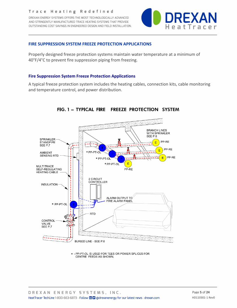
FIRE SUPPRESSION SYSTEM FREEZE PROTECTION APPLICATIONS
Properly designed freeze protection systems maintain water temperature at a minimum of 40°F/4°C to prevent fire suppression piping from freezing.
Fire Suppression System Freeze Protection Applications
A typical freeze protection system includes the heating cables, connection kits, cable monitoring and temperature control, and power distribution.
HD110301-1 Rev0
Page 6 of 24
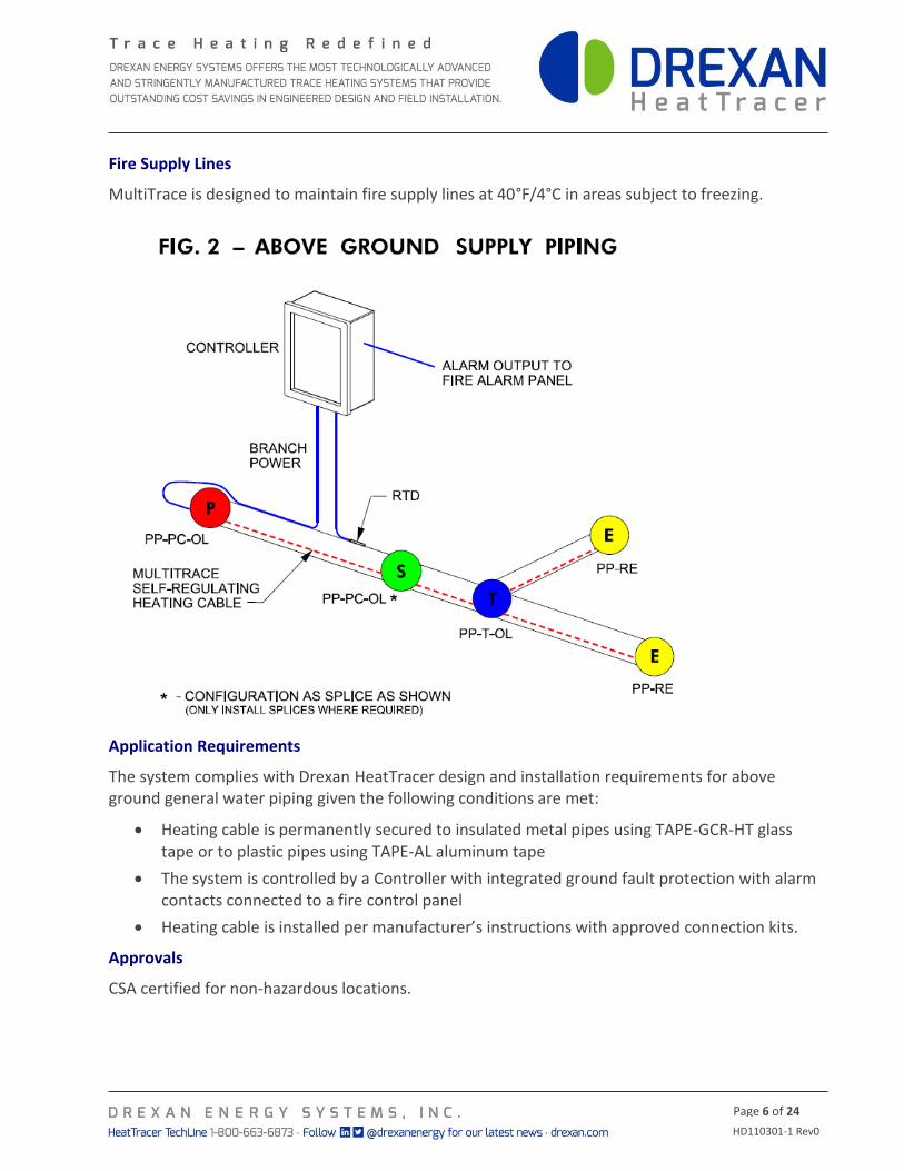
Fire Supply Lines
MultiTrace is designed to maintain fire supply lines at 40°F/4°C in areas subject to freezing.
Application Requirements
The system complies with Drexan HeatTracer design and installation requirements for above ground general water piping given the following conditions are met:
Heating cable is permanently secured to insulated metal pipes using TAPE-GCR-HT glass tape or to plastic pipes using TAPE-AL aluminum tape
The system is controlled by a Controller with integrated ground fault protection with alarm contacts connected to a fire control panel
Heating cable is installed per manufacturer’s instructions with approved connection kits.
Approvals
CSA certified for non-hazardous locations.
HD110301-1 Rev0
Page 7 of 24
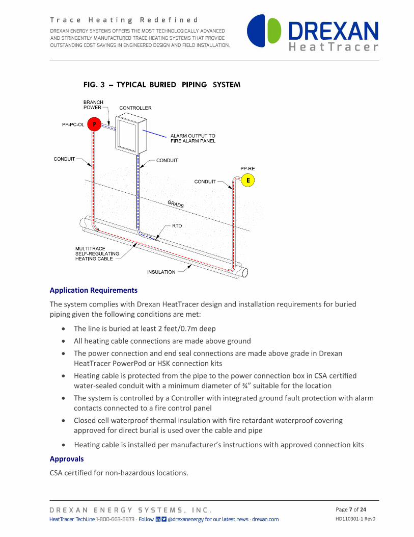
Application Requirements
The system complies with Drexan HeatTracer design and installation requirements for buried piping given the following conditions are met:
The line is buried at least 2 feet/0.7m deep
All heating cable connections are made above ground
The power connection and end seal connections are made above grade in Drexan HeatTracer PowerPod or HSK connection kits
Heating cable is protected from the pipe to the power connection box in CSA certified water-sealed conduit with a minimum diameter of ¾” suitable for the location
The system is controlled by a Controller with integrated ground fault protection with alarm contacts connected to a fire control panel
Closed cell waterproof thermal insulation with fire retardant waterproof covering approved for direct burial is used over the cable and pipe
Heating cable is installed per manufacturer’s instructions with approved connection kits
Approvals
CSA certified for non-hazardous locations.
HD110301-1 Rev0
Page 8 of 24
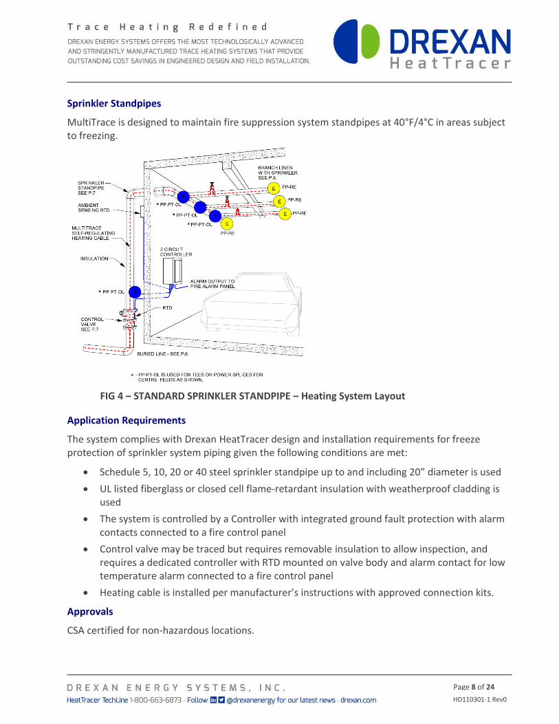
Sprinkler Standpipes
MultiTrace is designed to maintain fire suppression system standpipes at 40°F/4°C in areas subject to freezing.
FIG 4 – STANDARD SPRINKLER STANDPIPE – Heating System Layout
Application Requirements
The system complies with Drexan HeatTracer design and installation requirements for freeze protection of sprinkler system piping given the following conditions are met:
Schedule 5, 10, 20 or 40 steel sprinkler standpipe up to and including 20” diameter is used
UL listed fiberglass or closed cell flame-retardant insulation with weatherproof cladding is used
The system is controlled by a Controller with integrated ground fault protection with alarm contacts connected to a fire control panel
Control valve may be traced but requires removable insulation to allow inspection, and requires a dedicated controller with RTD mounted on valve body and alarm contact for low temperature alarm connected to a fire control panel
Heating cable is installed per manufacturer’s instructions with approved connection kits.
Approvals
CSA certified for non-hazardous locations.
HD110301-1 Rev0
Page 9 of 24
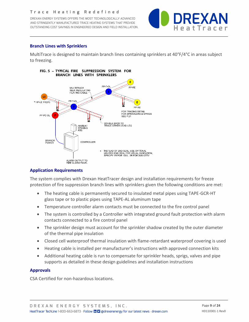
Branch Lines with Sprinklers
MultiTrace is designed to maintain branch lines containing sprinklers at 40°F/4°C in areas subject to freezing.
Application Requirements
The system complies with Drexan HeatTracer design and installation requirements for freeze protection of fire suppression branch lines with sprinklers given the following conditions are met:
The heating cable is permanently secured to insulated metal pipes using TAPE-GCR-HT glass tape or to plastic pipes using TAPE-AL aluminum tape
Temperature controller alarm contacts must be connected to the fire control panel
The system is controlled by a Controller with integrated ground fault protection with alarm contacts connected to a fire control panel
The sprinkler design must account for the sprinkler shadow created by the outer diameter of the thermal pipe insulation
Closed cell waterproof thermal insulation with flame-retardant waterproof covering is used
Heating cable is installed per manufacturer’s instructions with approved connection kits
Additional heating cable is run to compensate for sprinkler heads, sprigs, valves and pipe supports as detailed in these design guidelines and installation instructions
Approvals
CSA Certified for non-hazardous locations.
HD110301-1 Rev0
Page 10 of 24
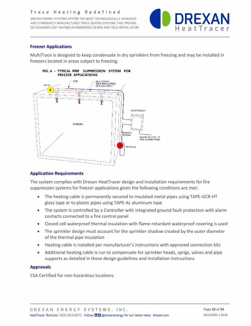
Freezer Applications
MultiTrace is designed to keep condensate in dry sprinklers from freezing and may be installed in freezers located in areas subject to freezing.
Application Requirements
The system complies with Drexan HeatTracer design and installation requirements for fire suppression systems for freezer applications given the following conditions are met:
The heating cable is permanently secured to insulated metal pipes using TAPE-GCR-HT glass tape or to plastic pipes using TAPE-AL aluminum tape
The system is controlled by a Controller with integrated ground fault protection with alarm contacts connected to a fire control panel
Closed cell waterproof thermal insulation with flame-retardant waterproof covering is used
The sprinkler design must account for the sprinkler shadow created by the outer diameter of the thermal pipe insulation
Heating cable is installed per manufacturer’s instructions with approved connection kits
Additional heating cable is run to compensate for sprinkler heads, sprigs, valves and pipe supports as detailed in these design guidelines and installation instructions
Approvals
CSA Certified for non-hazardous locations.
HD110301-1 Rev0
Page 11 of 24
FIRE SUPPRESSION SYSTEM FREEZE PROTECTION DESIGN GUIDE
This section provides step-by-step instructions to design a fire suppression freeze protection system. While the steps shown here allow for manual design, Drexan HeatTracer recommends the use of the ProTrace Design Software to provide a compliant design complete with estimates of power loads and detailed bills of material for the project.
STEP 1 – COLLECT THE REQUIRED INFORMATION FOR EACH LINE
Pipe diameter
Pipe length
Minimum ambient temperature
This is the minimum temperature expected (worst case) throughout the winter months2.
Maintain temperature
For freeze protection a typical maintain temperature of 4˚C/40˚F is sufficient.
Start-up temperature
This temperature will have a direct effect on the maximum circuit length and the breaker size required. You should select the temperature at which the cable will normally become energized, not necessarily the coldest temperature.
Metal or non-metallic Pipe
Some materials have superior heat transfer compared to others. For example metal will conduct heat better than a polymeric material. For this reason we require the use of aluminum foil tape (part# TAPE-AL) on polymeric pipes applied over the pipe under the cable.
Pipe hardware (valves, shoes, flanges etc.)
When measuring the total length of the pipe to be heat traced remember to allow extra cable for the pipe hardware.
Thermal Insulation type & thickness
All pipes, equipment and pipe hardware must be thermally insulated as specified in the previous section.
Measurement: Metric? Imperial? Temperature: Celsius? Fahrenheit?
Voltage: (include if 3 phase) _____________
APPLICATIONS
Pipe Tracing: Metal? Other? (specify) _______
Pipe Length: _____________ Diameter: __________ Insulation Type: _______
Insulation Thickness: __________ Not Yet Determined __________
Low Ambient Temp: ______ Max. Pipe Temp: ______ Maintain Temp: ______
Number of Supports ______ Valves _______ Hangers ______
2 If in doubt, refer to historical data at: http://climate.weather.gc.ca/index_e.html
HD110301-1 Rev0
Page 12 of 24
STEP 2 – DESIGN CONSIDERATIONS
When a pipe enters the heated area of a building it is important that the cable extends into the building approximately 12” to ensure the pipe temperature is maintained above freezing.
When a pipe enters the ground to below the frost line it is important to run the cable well below the frost line (a minimum of 2 feet) to ensure the pipe temperature is maintained above freezing.
When a main pipe has a short branch line connected to it, the branch line may be double-traced (down & back) to eliminate the need for a Tee Splice Kit. Refer to detail in Figure 5.
Heating cable should not pass through the air. When crossing from one pipe to another, the cable should run through a Flexible Extension (FLEX-E).
Select the cable wattage output to suit the application. A conservative design will specify a slightly higher wattage output per foot of cable than required. However this will consume more electrical power over time and is not required with a correctly designed system.
A lower wattage cable has a longer circuit length. On projects with long runs, this reduces the number of circuits, thereby lowering component and circuit costs and increasing reliability by reducing the number of potential failure points in each connection. Always design to use the lowest wattage heater for the given design conditions – it is bad practice to use higher wattage cables than necessary.
Insulate all heat sinks (pipe hangars, pipe shoes, valves) in the heat tracing system. Allow sufficient cable to trace additional heat sinks. Refer to Table 2.
DO NOT expose heating cables to temperatures higher than their temperature ratings.
For valves, install the heating cable so that the valves can be conveniently removed for servicing.
The type and thickness of thermal insulation will have a direct effect on the amount of heat required. Longer circuit lengths may be achieved by increasing the insulating thermal value to lower the cable wattage output required. Refer to Table 1.
Multiple runs of cable may be required on larger pipes with high heat loss.
HD110301-1 Rev0
Page 13 of 24
STEP 3 – ELECTRICAL REQUIREMENTS
Design the heat tracing system using the most commonly expected start-up temperature.
Be practical. If you choose the most extreme (coldest possible) start-up temperature, for example -40 degrees, you may unnecessarily shorten the circuit lengths, or require larger breaker sizes or additional panels and power cable. However, keep in mind that if the heating system starts up at a lower temperature than it was designed for, you may experience breaker tripping. Since fire sprinkler systems are controlled to power on at 4°C/40°F, this temperature may be used for start-up design.
To determine maximum circuit length and breaker size required, refer to tables found on the cable data sheets available at http://www.drexan.com/
For voltages other than 120/240V refer to cable data sheets at http://www.drexan.com/
All heating cable systems require ground fault protection (27 or 30 mA trip level) as per the National and Canadian Electrical Codes. This protection is provided in Drexan’s recommended Controllers.
STEP 4 – SELECTING CABLE POWER OUTPUT
When determining the minimum ambient temperature for your location, always consider the worst case or lowest temperature. Selecting a low ambient design temperature will provide an increased safety factor.
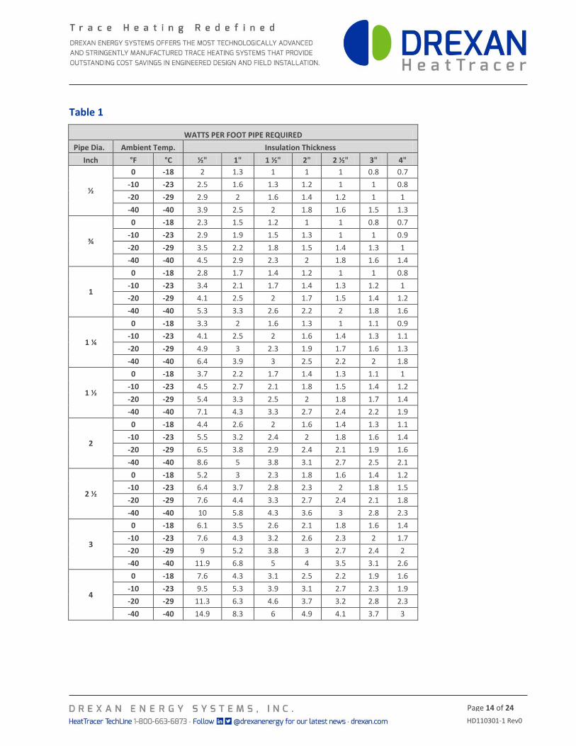
From the following tables you can determine the amount of heat (watts/ft pipe) required to maintain your pipe @ 40°F/4°C. MultiTrace is available in 4 nominal power outputs: 3W, 5W, 8W and 10W per foot. If higher watt densities per foot are required, run multiple tracers on the line. E.g. if 20W per foot is required, run 2 lengths of 10W cable.
For example: An ambient temperature of minus -20°F/-29°C and a 2” pipe with 1” of Glass Fiber thermal insulation will require 3.8 Watts/foot of pipe.
Note: The charts used in this guide are based on Glass Fiber Thermal Insulation. These charts may also be used with Polyisocyanurate and Mineral Wool insulations of the same thickness.
Note: refer to the MultiTrace cable data sheet located on the Drexan HeatTracer Website: http://www.drexan.com/
HD110301-1 Rev0
Page 14 of 24
Table 1
WATTS PER FOOT PIPE REQUIRED
Pipe Dia. Ambient Temp. Insulation Thickness
Inch °F °C ½" 1" 1 ½" 2" 2 ½" 3" 4"
½
0 -18 2 1.3 1 1 1 0.8 0.7
-10 -23 2.5 1.6 1.3 1.2 1 1 0.8
-20 -29 2.9 2 1.6 1.4 1.2 1 1
-40 -40 3.9 2.5 2 1.8 1.6 1.5 1.3
¾
0 -18 2.3 1.5 1.2 1 1 0.8 0.7
-10 -23 2.9 1.9 1.5 1.3 1 1 0.9
-20 -29 3.5 2.2 1.8 1.5 1.4 1.3 1
-40 -40 4.5 2.9 2.3 2 1.8 1.6 1.4
1
0 -18 2.8 1.7 1.4 1.2 1 1 0.8
-10 -23 3.4 2.1 1.7 1.4 1.3 1.2 1
-20 -29 4.1 2.5 2 1.7 1.5 1.4 1.2
-40 -40 5.3 3.3 2.6 2.2 2 1.8 1.6
1 ¼
0 -18 3.3 2 1.6 1.3 1 1.1 0.9
-10 -23 4.1 2.5 2 1.6 1.4 1.3 1.1
-20 -29 4.9 3 2.3 1.9 1.7 1.6 1.3
-40 -40 6.4 3.9 3 2.5 2.2 2 1.8
1 ½
0 -18 3.7 2.2 1.7 1.4 1.3 1.1 1
-10 -23 4.5 2.7 2.1 1.8 1.5 1.4 1.2
-20 -29 5.4 3.3 2.5 2 1.8 1.7 1.4
-40 -40 7.1 4.3 3.3 2.7 2.4 2.2 1.9
2
0 -18 4.4 2.6 2 1.6 1.4 1.3 1.1
-10 -23 5.5 3.2 2.4 2 1.8 1.6 1.4
-20 -29 6.5 3.8 2.9 2.4 2.1 1.9 1.6
-40 -40 8.6 5 3.8 3.1 2.7 2.5 2.1
2 ½
0 -18 5.2 3 2.3 1.8 1.6 1.4 1.2
-10 -23 6.4 3.7 2.8 2.3 2 1.8 1.5
-20 -29 7.6 4.4 3.3 2.7 2.4 2.1 1.8
-40 -40 10 5.8 4.3 3.6 3 2.8 2.3
3
0 -18 6.1 3.5 2.6 2.1 1.8 1.6 1.4
-10 -23 7.6 4.3 3.2 2.6 2.3 2 1.7
-20 -29 9 5.2 3.8 3 2.7 2.4 2
-40 -40 11.9 6.8 5 4 3.5 3.1 2.6
4
0 -18 7.6 4.3 3.1 2.5 2.2 1.9 1.6
-10 -23 9.5 5.3 3.9 3.1 2.7 2.3 1.9
-20 -29 11.3 6.3 4.6 3.7 3.2 2.8 2.3
-40 -40 14.9 8.3 6 4.9 4.1 3.7 3

HD110301-1 Rev0
Page 15 of 24
Table 1 cont.
WATTS PER FOOT PIPE REQUIRED
Pipe Dia. Ambient Temp. Insulation Thickness
Inch °F °C ½" 1" 1 ½" 2" 2 ½" 3" 4"
6
0 -18 11 6 4.6 3.4 2.8 2.5 2
-10 -23 13.5 7.4 5.3 4.2 3.5 3.1 2.5
-20 -29 16 8.8 6.3 5 4.2 3.7 3
-40 -40 21.1 11.6 8.2 6.5 5.5 4.8 3.9
8
0 -18 14 7.5 5.3 4.2 3.5 3 2.4
-10 -23 17.2 9.3 6.6 5.2 4.3 3.8 3
-20 -29 20.5 11 7.8 6.2 5.2 4.5 3.6
-40 -40 27 14.6 10.3 8.1 6.8 5.9 4.7
10
0 -18 17 9.2 6.4 5 4.2 4 3
-10 -23 21 11.4 8 6.2 5.2 5 4
-20 -29 26 13.6 10 7.4 6.2 5.3 4.2
-40 -40 34 18 13 10 8.1 7 6
12
0 -18 20 11 8 6 5 4.2 3.3
-10 -23 25 13.3 9.3 7.2 6 5.1 4.1
-20 -29 30 16 11 9 7 6.1 5
-40 -40 39 21 15 11.3 9.3 8 6.4
14
0 -18 22 12 8 6.3 5.2 5 4
-10 -23 27.2 15 10 8 7 6 4.4
-20 -29 33 17.3 12 9.3 8 7 5.2
-40 -40 43 23 16 12.2 10.1 9 7
16
0 -18 25 13.2 9.2 7.1 6 5 4
-10 -23 31 17 11.4 9 7.3 6.2 5
-20 -29 37 20 14 11 9 7.4 6
-40 -40 48.5 26 18 14 11.3 10 8
18
0 -18 28 15 10.2 8 7 6 4.3
-10 -23 35 19 13 10 8 7 5.4
-20 -29 42 22 15 12 10 8.2 6.4
-40 -40 54.3 29 20 15.3 13 11 8.4
20
0 -18 31 17 11.3 9 7 6.1 5
-10 -23 38 21 14 11 9 8 6
-20 -29 46 24 17 13 11 9 7
-40 -40 60.2 32 22 17 14 12 9.2
24
0 -18 37 20 14 11 9 7.1 6
-10 -23 46 24 17 13 11 9 7
-20 -29 55 29 20 15 13 11 8
-40 -40 72 38 26 20 16.3 14 11
HD110301-1 Rev0
Page 16 of 24
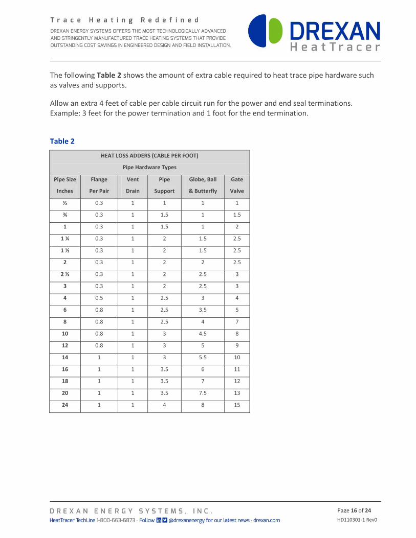
The following Table 2 shows the amount of extra cable required to heat trace pipe hardware such as valves and supports.
Allow an extra 4 feet of cable per cable circuit run for the power and end seal terminations. Example: 3 feet for the power termination and 1 foot for the end termination.
Table 2
HEAT LOSS ADDERS (CABLE PER FOOT)
Pipe Hardware Types
Pipe Size
Inches
Flange
Per Pair
Vent
Drain
Pipe
Support
Globe, Ball
& Butterfly
Gate
Valve
½ 0.3 1 1 1 1
¾ 0.3 1 1.5 1 1.5
1 0.3 1 1.5 1 2
1 ¼ 0.3 1 2 1.5 2.5
1 ½ 0.3 1 2 1.5 2.5
2 0.3 1 2 2 2.5
2 ½ 0.3 1 2 2.5 3
3 0.3 1 2 2.5 3
4 0.5 1 2.5 3 4
6 0.8 1 2.5 3.5 5
8 0.8 1 2.5 4 7
10 0.8 1 3 4.5 8
12 0.8 1 3 5 9
14 1 1 3 5.5 10
16 1 1 3.5 6 11
18 1 1 3.5 7 12
20 1 1 3.5 7.5 13
24 1 1 4 8 15
HD110301-1 Rev0
Page 17 of 24
STEP 5 – CABLE COMPONENTS
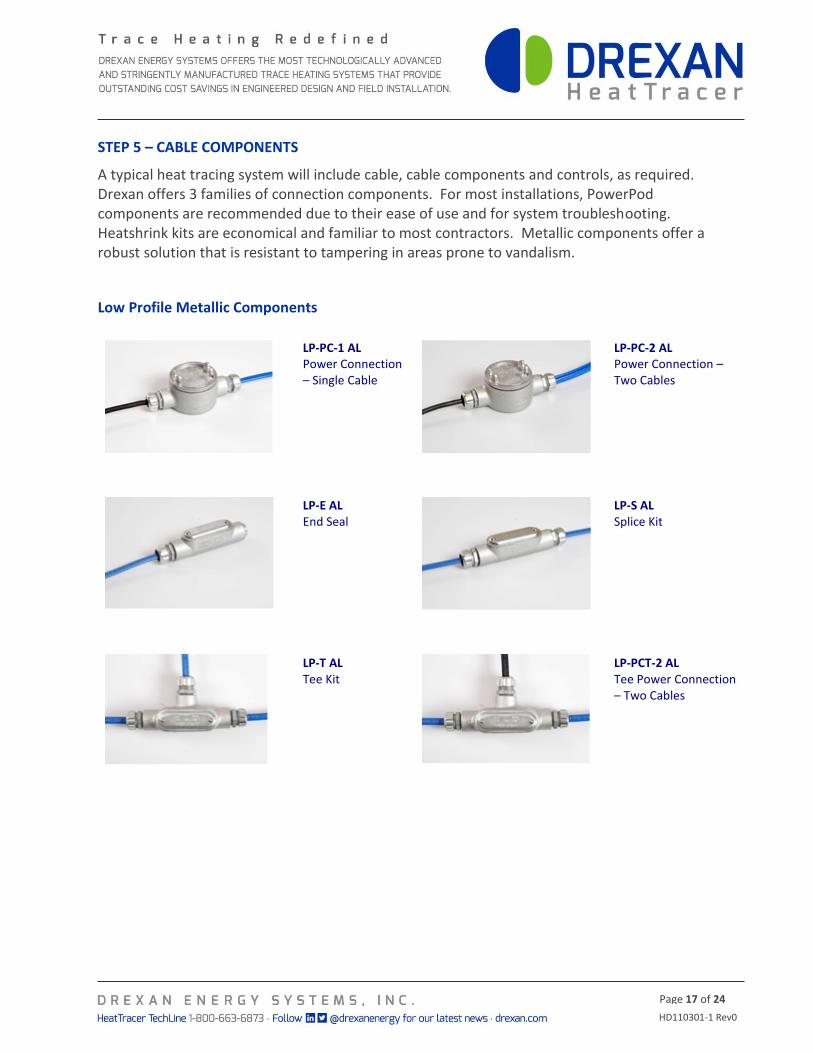
A typical heat tracing system will include cable, cable components and controls, as required. Drexan offers 3 families of connection components. For most installations, PowerPod components are recommended due to their ease of use and for system troubleshooting. Heatshrink kits are economical and familiar to most contractors. Metallic components offer a robust solution that is resistant to tampering in areas prone to vandalism.
Low Profile Metallic Components
LP-PC-1 AL Power Connection – Single Cable
LP-PC-2 AL Power Connection – Two Cables
LP-E AL End Seal
LP-S AL Splice Kit
LP-T AL Tee Kit
LP-PCT-2 AL Tee Power Connection – Two Cables
HD110301-1 Rev0
Page 18 of 24
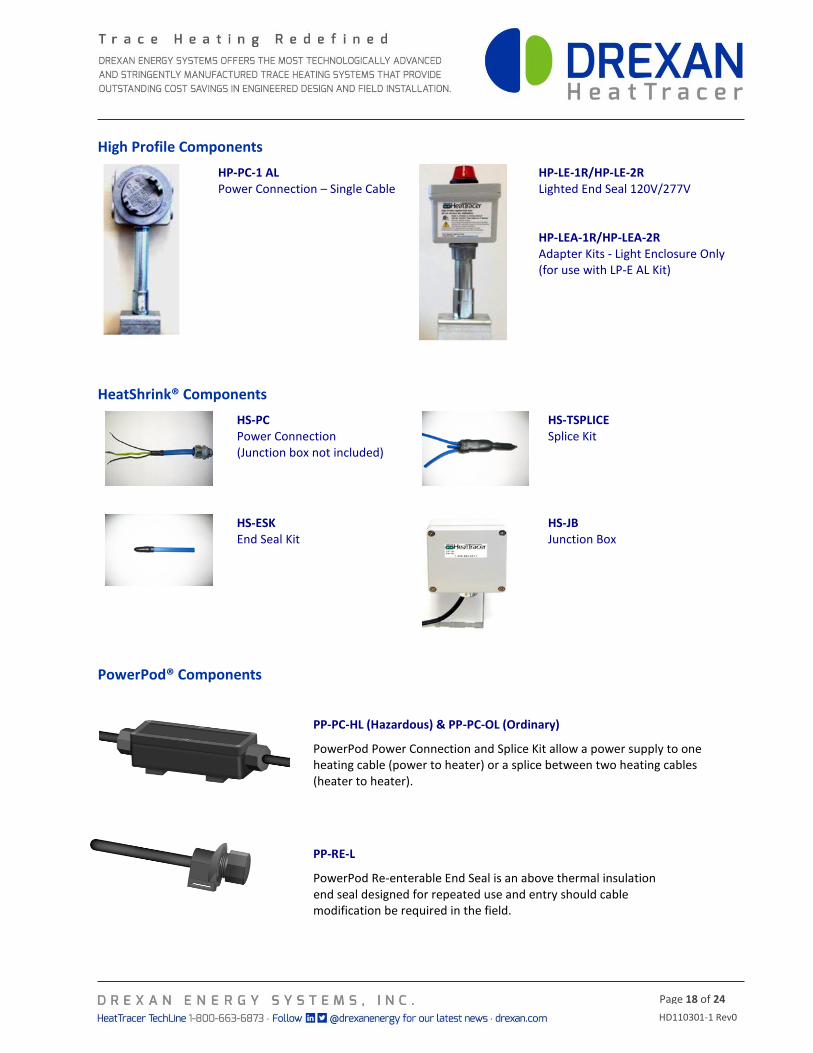
High Profile Components
HP-PC-1 AL Power Connection – Single Cable
HP-LE-1R/HP-LE-2R Lighted End Seal 120V/277V HP-LEA-1R/HP-LEA-2R Adapter Kits - Light Enclosure Only (for use with LP-E AL Kit)
HeatShrink® Components
HS-PC Power Connection (Junction box not included)
HS-TSPLICE Splice Kit
HS-ESK End Seal Kit
HS-JB Junction Box
PowerPod® Components
PP-PC-HL (Hazardous) & PP-PC-OL (Ordinary)
PowerPod Power Connection and Splice Kit allow a power supply to one heating cable (power to heater) or a splice between two heating cables (heater to heater).
PP-RE-L
PowerPod Re-enterable End Seal is an above thermal insulation end seal designed for repeated use and entry should cable modification be required in the field.
HD110301-1 Rev0
Page 19 of 24
STEP 6 – POWER DISTRIBUTION
Power to the heating cables can be provided directly or through external contactors. For large jobs where power distribution panels are desired, contact Drexan HeatTracer for design and delivery.
Single circuit control: Heating cable circuits that do not exceed the current rating of the selected Controllers can be switched directly.
Group control: If current draw of the system exceeds the switch rating, or if the controller will activate more than one circuit in group control, an external contactor must be used.
HD110301-1 Rev0
Page 20 of 24
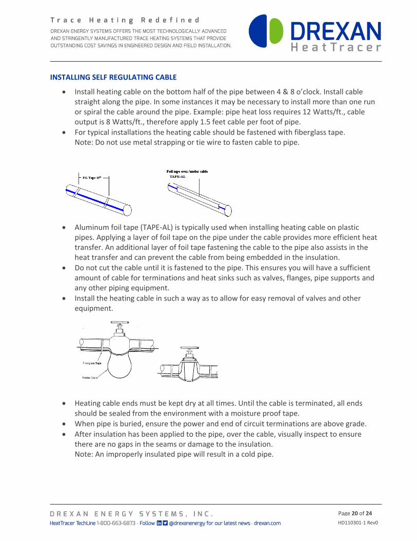
INSTALLING SELF REGULATING CABLE
Install heating cable on the bottom half of the pipe between 4 & 8 o’clock. Install cable straight along the pipe. In some instances it may be necessary to install more than one run or spiral the cable around the pipe. Example: pipe heat loss requires 12 Watts/ft., cable output is 8 Watts/ft., therefore apply 1.5 feet cable per foot of pipe.
For typical installations the heating cable should be fastened with fiberglass tape. Note: Do not use metal strapping or tie wire to fasten cable to pipe.
Aluminum foil tape (TAPE-AL) is typically used when installing heating cable on plastic pipes. Applying a layer of foil tape on the pipe under the cable provides more efficient heat transfer. An additional layer of foil tape fastening the cable to the pipe also assists in the heat transfer and can prevent the cable from being embedded in the insulation.
Do not cut the cable until it is fastened to the pipe. This ensures you will have a sufficient amount of cable for terminations and heat sinks such as valves, flanges, pipe supports and any other piping equipment.
Install the heating cable in such a way as to allow for easy removal of valves and other equipment.
Heating cable ends must be kept dry at all times. Until the cable is terminated, all ends should be sealed from the environment with a moisture proof tape.
When pipe is buried, ensure the power and end of circuit terminations are above grade.
After insulation has been applied to the pipe, over the cable, visually inspect to ensure there are no gaps in the seams or damage to the insulation. Note: An improperly insulated pipe will result in a cold pipe.
HD110301-1 Rev0
Page 21 of 24
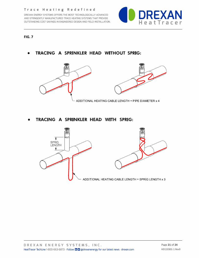
FIG. 7
HD110301-1 Rev0
Page 22 of 24
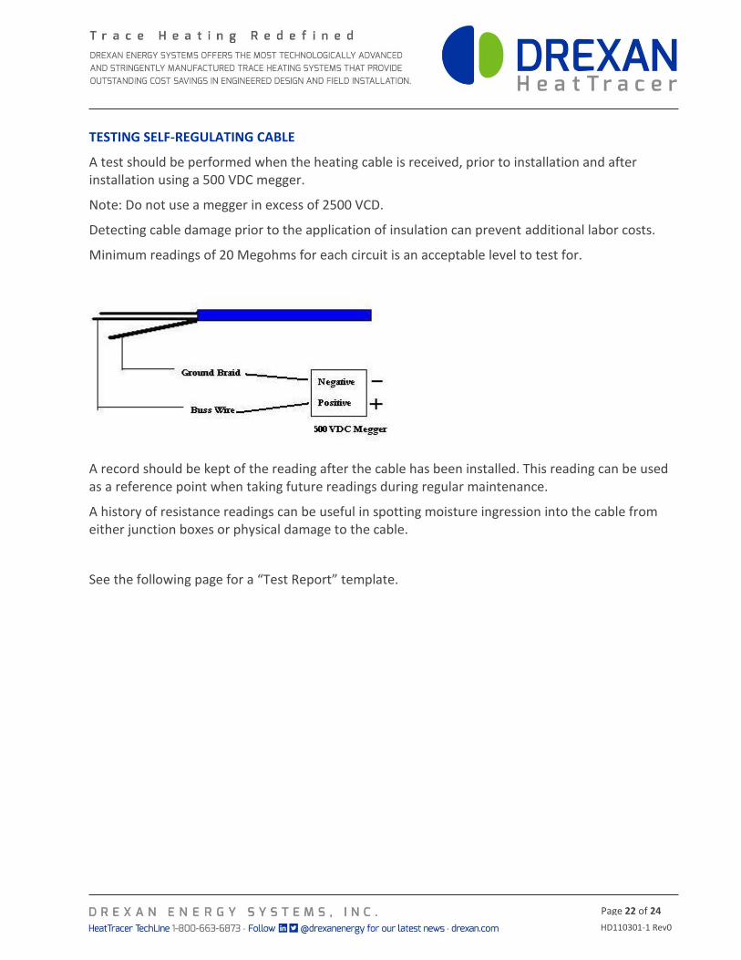
TESTING SELF-REGULATING CABLE
A test should be performed when the heating cable is received, prior to installation and after installation using a 500 VDC megger.
Note: Do not use a megger in excess of 2500 VCD.
Detecting cable damage prior to the application of insulation can prevent additional labor costs.
Minimum readings of 20 Megohms for each circuit is an acceptable level to test for.
A record should be kept of the reading after the cable has been installed. This reading can be used as a reference point when taking future readings during regular maintenance.
A history of resistance readings can be useful in spotting moisture ingression into the cable from either junction boxes or physical damage to the cable.
See the following page for a “Test Report” template.
HD110301-1 Rev0
Page 23 of 24
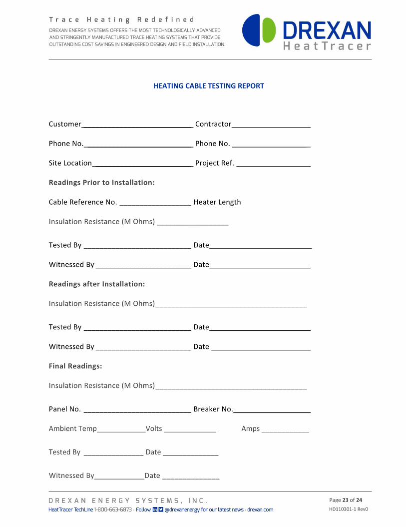
HEATING CABLE TESTING REPORT
Customer ___________________________ Contractor
Phone No. __________________________ Phone No. _
Site Location ________________________ Project Ref.
Readings Prior to Installation:
Cable Reference No. __________________ Heater Length
Insulation Resistance (M Ohms) __________________
Tested By ___________________________ Date
Witnessed By ________________________ Date
Readings after Installation:
Insulation Resistance (M Ohms) ______________________________________
Tested By ___________________________ Date
Witnessed By ________________________ Date
Final Readings:
Insulation Resistance (M Ohms) ______________________________________
Panel No. ___________________________ Breaker No.
Ambient Temp ___________ Volts Amps ____________
Tested By _______________ Date ______________
Witnessed By Date ______________
HD110301-1 Rev0
Page 24 of 24
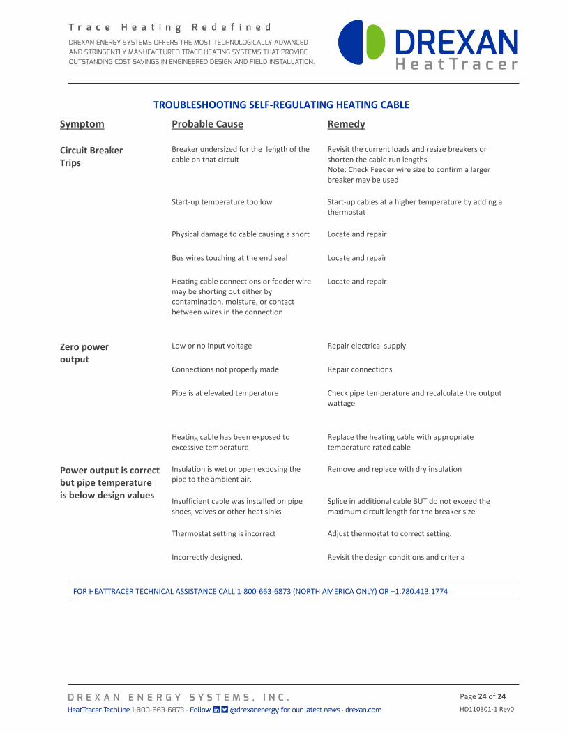
TROUBLESHOOTING SELF-REGULATING HEATING CABLE
Symptom
Probable Cause
Remedy
Circuit Breaker Trips
Breaker undersized for the length of the cable on that circuit
Revisit the current loads and resize breakers or shorten the cable run lengths
Note: Check Feeder wire size to confirm a larger breaker may be used
Start-up temperature too low Start-up cables at a higher temperature by adding a thermostat
Physical damage to cable causing a short Locate and repair
Bus wires touching at the end seal Locate and repair
Heating cable connections or feeder wire may be shorting out either by contamination, moisture, or contact between wires in the connection
Locate and repair
Zero power output
Low or no input voltage Repair electrical supply
Connections not properly made Repair connections
Pipe is at elevated temperature Check pipe temperature and recalculate the output wattage
Heating cable has been exposed to excessive temperature
Replace the heating cable with appropriate temperature rated cable
Power output is correct but pipe temperature is below design values
Insulation is wet or open exposing the pipe to the ambient air.
Remove and replace with dry insulation
Insufficient cable was installed on pipe shoes, valves or other heat sinks
Splice in additional cable BUT do not exceed the maximum circuit length for the breaker size
Thermostat setting is incorrect Adjust thermostat to correct setting.
Incorrectly designed. Revisit the design conditions and criteria
FOR HEATTRACER TECHNICAL ASSISTANCE CALL 1-800-663-6873 (NORTH AMERICA ONLY) OR +1.780.413.1774