Embed Size (px)
Citation preview

For more information, visit www.fmiproducts.com
OWNER’S OPERATION AND INSTALLATION MANUAL
FIRE RING MODELSMM2FR, MM2FRL, MM3FR AND MM3FRLNATURAL GAS BURNER MODELS:
MMFRBNB AND MMFRBNSPROPANE/LP GAS BURNER
MODELS:MMFRBPB AND MMFRBPS
WARNING: Improper installation, adjust-ment, alteration, service or maintenance can cause injury or property damage. Read the installation, operating and maintenance instructions thoroughly before installing or servicing this equipment.
WARNING: Do not store gasoline or other flammable vapors and liquids in the vicinity of this or any other appliance. An LP-cylinder not connected for use shall not be stored in the vicinity of this or any other appliance.
WARNING: For Outdoor Use Only.
CARBON MONOXIDE WARNING
• This appliance can pro-duce carbon monoxide which has no odor.
• Using it in an enclosed space can kill you.
• Never use this appliance in an enclosed space such as a camper, tent, car or home.
DANGERIF YOU SMELL GAS:1. Shut off gas to appliance.2. Extinguish any open flame.3. If odor continues, keep away from the
appliance and immediately call your gas supplier or fire department.
INSTALLER: Leave this manual with the appliance.CONSUMER: Retain this manual for future reference.
DANGER
www.fmiproducts.com 125883-01C2
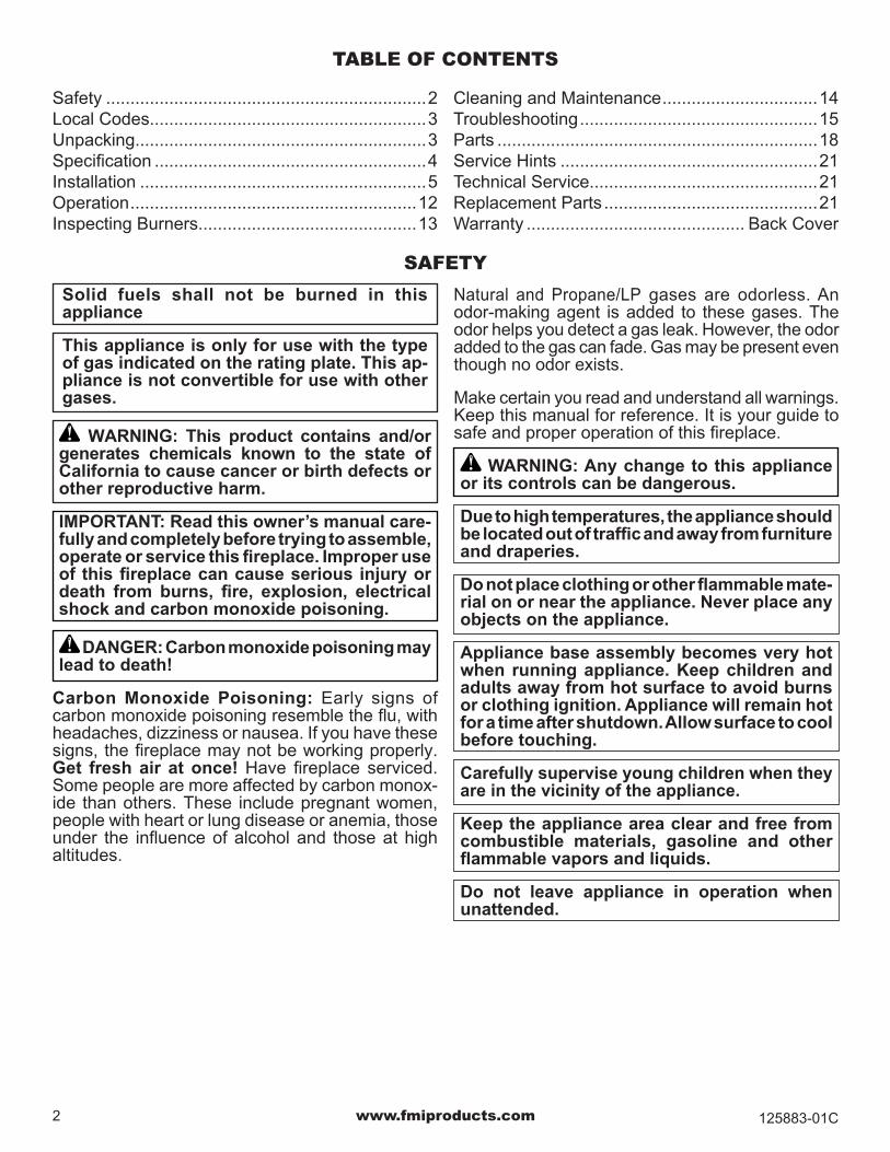
Natural and Propane/LP gases are odorless. An odor-making agent is added to these gases. The odor helps you detect a gas leak. However, the odor added to the gas can fade. Gas may be present even though no odor exists.
Make certain you read and understand all warnings. Keep this manual for reference. It is your guide to safe and proper operation of this fireplace.
WARNING: Any change to this appliance or its controls can be dangerous.
Due to high temperatures, the appliance should be located out of traffic and away from furniture and draperies.
Do not place clothing or other flammable mate-rial on or near the appliance. Never place any objects on the appliance.
Appliance base assembly becomes very hot when running appliance. Keep children and adults away from hot surface to avoid burns or clothing ignition. Appliance will remain hot for a time after shutdown. Allow surface to cool before touching.
Carefully supervise young children when they are in the vicinity of the appliance.
Keep the appliance area clear and free from combustible materials, gasoline and other flammable vapors and liquids.
Do not leave appliance in operation when unattended.
Solid fuels shall not be burned in this appliance
This appliance is only for use with the type of gas indicated on the rating plate. This ap-pliance is not convertible for use with other gases.
WARNING: This product contains and/or generates chemicals known to the state of California to cause cancer or birth defects or other reproductive harm.
IMPORTANT: Read this owner’s manual care-fully and completely before trying to assemble, operate or service this fireplace. Improper use of this fireplace can cause serious injury or death from burns, fire, explosion, electrical shock and carbon monoxide poisoning.
DANGER: Carbon monoxide poisoning may lead to death!
Carbon Monoxide Poisoning: Early signs of carbon monoxide poisoning resemble the flu, with headaches, dizziness or nausea. If you have these signs, the fireplace may not be working properly. Get fresh air at once! Have fireplace serviced. Some people are more affected by carbon monox-ide than others. These include pregnant women, people with heart or lung disease or anemia, those under the influence of alcohol and those at high altitudes.
SAFETY
TABLE OF CONTENTS
Safety ..................................................................2Local Codes.........................................................3Unpacking............................................................3Specification ........................................................4Installation ...........................................................5Operation ...........................................................12Inspecting Burners.............................................13
Cleaning and Maintenance ................................14Troubleshooting .................................................15Parts ..................................................................18Service Hints .....................................................21Technical Service...............................................21Replacement Parts ............................................21Warranty ............................................. Back Cover

www.fmiproducts.com125883-01C 3
SAFETYContinued
1. This appliance is only for use with the type of gas indicated on the rating plate. This appliance is not convertible for use with other gases.
2. Do not place propane/LP supply tank(s) inside or under the fire ring. Locate propane/LP supply tank(s) at least 10 feet away (propane/LP units only).
3. If you smell gas• shut off gas supply• do not try to light any appliance• do not touch any electrical switch; do not use any phone in your building
• immediately call your gas supplier from a neigh-bor’s phone. Follow the gas supplier’s instruc-tions
• if you cannot reach your gas supplier, call the fire department
4. To prevent the creation of soot, follow the instruc-tions in Cleaning and Maintenance, page 14.
5. Do not run appliance• where flammable liquids or vapors are used or stored
• under dusty conditions6. Do not use this appliance to cook food or burn
paper or other objects.
7. Do not use this appliance if any part has been exposed to or under water. Immediately call a qualified service technician to inspect the room appliance and to replace any part of the control system and any gas control which has been un-der water.
8. Turn appliance off and let cool before servicing, installing or repairing. Only a qualified service person should install, service or repair appliance.
9. This appliances must not be connected to any external electrical source.
10.Operating appliance above elevations of 4,500 feet may cause pilot outage.
17.To prevent performance problems, do not use propane/LP fuel tank of less than 100 lb. capacity (propane/LP units only).
18.Provide adequate clearances around air open-ings.
LOCAL CODESInstall and use appliance with care. Follow all local codes. In the absence of local codes, use the lat-est edition of The National Fuel Gas Code, ANSI Z223.1/NFPA 54*.*Available from:
American National Standards Institute, Inc.1430 Broadway
New York, NY 10018National Fire Protection Association, Inc.
Batterymarch ParkQuincy, MA 02269
UNPACKING1. Remove burner system and other components
from box. Do not grasp by burner tubes. If it is evident that the burner is damaged, it must be replaced prior to being put into operation. Set lava rock boxes aside for further instruction.
2. Remove all protective packaging from pallet of blocks for shipment.
3. Check for any shipping damage. If appliance is damaged call FMI PRODUCTS, LLC at 1-866-328-4537 for replacement parts before returning to dealer.

www.fmiproducts.com 125883-01C4
50.625” 29.125”
47.875”
MM2FR: 17.125”MM3FR: 24.250”
SPECIFICATIONS
Figure 1 - MODELS MM2FR, MM2FRL, MM3FR AND MM3FRL
MMFRBNB, MMFRBNS• Rating: 96,000 Btu/hr• Gas Type: Natural Gas Only• Ignition: Manual• Manifold Pressure: 6.0" w.c.• Minimum Inlet Supply Pressure: 7.0" w.c.• Maximum Inlet Supply Pressure: 10.5" w.c.• Orifice: #12
MMFRBPB, MMFRBPS• Rating: 95,000 Btu/hr• Gas Type: Propane/LP Gas Only• Ignition: Manual• Manifold Pressure: 10.5" w.c.• Minimum Inlet Supply Pressure: 11" w.c.• Maximum Inlet Supply Pressure: 14" w.c.• Orifice: #33

www.fmiproducts.com125883-01C 5
INSTALLATION
WARNING: A qualified service person must install appliance. Follow all local codes.
NOTICE: State or local codes may only allow operation of this appliance in a vented con-figuration. Check your state or local codes.
CHECK GAS TYPEUse the correct type of gas (natural or propane/LP). If your gas supply is not the correct gas type, do not install appliance. Call dealer where you bought appliance for proper type appliance.
WARNING: This appliance is equipped for either natural gas or propane/LP gas but not both. Gas type is indicated on the rating plate. Field conversion is not permitted.
INSTALLATION AND CLEARANCES
WARNING: Maintain the minimum clearances. If you can, provide greater clearances from floor and adjoining wall.
MINIMUM CLEARANCE TO COMBUSTIBLE MATERIALS
Side Wall 16", Bottom: 0"
WARNING: DO NOT PLACE UNDER A CEILING OR OVERHANG.
CONNECTING TO GAS SUPPLY
WARNING: This appliance requires a 1/2" NPT (National Pipe Thread) inlet connection to the pressure regulator.
WARNING: A qualified service person must connect appliance to gas supply. Follow all local codes.
CAUTION: Never connect propane/LP fire ring directly to the propane/LP supply. This appliance requires an external regulator (not supplied). Install the external regulator be-tween the appliance and propane/LP supply.
WARNING: Never connect natural gas fire ring to private (non-utility) gas wells. This gas is commonly known as wellhead gas.
Installation Items NeededBefore installing appliance, make sure you have the items listed below.• external regulator (supplied by installer)• piping (check local codes)• sealant (resistant to propane/LP gas)• equipment shutoff valve *• test gauge connection *• sediment trap• tee joint• pipe wrench• approved flexible gas line with gas connector (if
allowed by local codes) (not provided) * An equipment shutoff valve with 1/8" NPT tap is an acceptable alternative to test gauge connection. Purchase the optional equipment shutoff valve from your dealer.For propane/LP units, the installer must supply an external regulator. The external regulator will reduce incoming gas pressure. You must reduce incoming gas pressure to between 11" and 14" of water. If you do not reduce incoming gas pressure, appli-ance regulator damage could occur. Install external regulator with the vent pointing down as shown in Figure 2, page 6. Pointing the vent down protects it from freezing rain or sleet.

www.fmiproducts.com 125883-01C6
We recommend that you install a sediment trap in supply line as shown in Figure 3. Locate sediment trap where it is within reach for cleaning. Install in piping system between fuel supply and appliance. Locate sediment trap where trapped matter is not likely to freeze. A sediment trap traps moisture and contaminants. This keeps them from going into ap-pliance controls. If sediment trap is not installed or is installed wrong, appliance may not run properly.
CAUTION: Avoid damage to gas control. Hold gas control with wrench when connect-ing it to gas piping and/or fittings.
CAUTION: Use only new, black iron or steel pipe. Internally-tinned copper tubing may be used in certain areas. Check your local codes. Use pipe of 1/2" diameter or greater to allow proper gas volume to appli-ance. If pipe is too small, undue loss of volume will occur.
Installation must include an equipment shutoff valve, union and plugged 1/8" NPT tap. Locate NPT tap within reach for test gauge hook up. NPT tap must be upstream from appliance (see Figure 3).IMPORTANT: Install equipment shutoff valve in an accessible location. The equipment shutoff valve is for turning on or shutting off the gas to the appliance.Check your building codes for any special require-ments for locating equipment shutoff valve to fire-places.Apply pipe joint sealant lightly to male NPT threads. This will prevent excess sealant from going into pipe. Excess sealant in pipe could result in clogged appliance valves.
WARNING: Use pipe joint sealant that is resistant to liquid petroleum (LP) gas.
Figure 2 - External Regulator With Vent Pointing Down
Propane/LP Supply Tank
External Regulator with Vent Pointing Down
INSTALLATIONContinued
* Purchase the optional equipment shutoff valve from your dealer.
**Minimum inlet pressure for purpose of input ad-justment.
Figure 3 - Gas Connection
3" Minimum
Equipment Shutoff Valve
With 1/8" NPT Tap*
Approved Flexible Gas Hose (no longer than 36" if required by local codes)
Tee Pipe CapJoint Nipple
Sediment Trap
PROPANE/LP From External
Regulator(11" W.C.** to 14" W.C.
Pressure)
NATURAL From Gas
Meter(7" W.C.**
to 10.5" W.C.
Pressure)
www.fmiproducts.com125883-01C 7
INSTALLATIONContinued
CHECKING GAS CONNECTIONS
WARNING: Test all gas piping and connec-tions, internal and external to unit, for leaks after installing or servicing. Correct all leaks at once.
WARNING: Never use an open flame to check for a leak. Apply a noncorrosive leak detection fluid to all joints. Bubbles forming show a leak. Correct all leaks at once.
CAUTION: Make sure external regulator has been installed between propane/LP supply and appliance. See guidelines under Connecting to Gas Supply, page 6.
PRESSURE TESTING GAS SUPPLY PIPING SYSTEM Test Pressures In Excess Of 1/2 PSIG (3.5 kPa)1. Disconnect appliance with its appliance main gas
valve (control valve) and equipment shutoff valve from gas supply piping system. Pressures in ex-cess of 1/2 psig will damage appliance regulator.
2. Cap off open end of gas pipe where equipment shutoff valve was connected.
3. Pressurize supply piping system by either open-ing propane/LP supply tank valve for propane/LP gas or opening main gas valve located on or near gas meter for natural gas or using compressed air.
4. Check all joints of gas supply piping system. Ap-ply noncorrosive leak detection fluid to all joints. Bubbles forming show a leak.
5. Correct all leaks at once.6. Reconnect appliance and equipment shutoff
valve to gas supply. Check reconnected fittings for leaks.
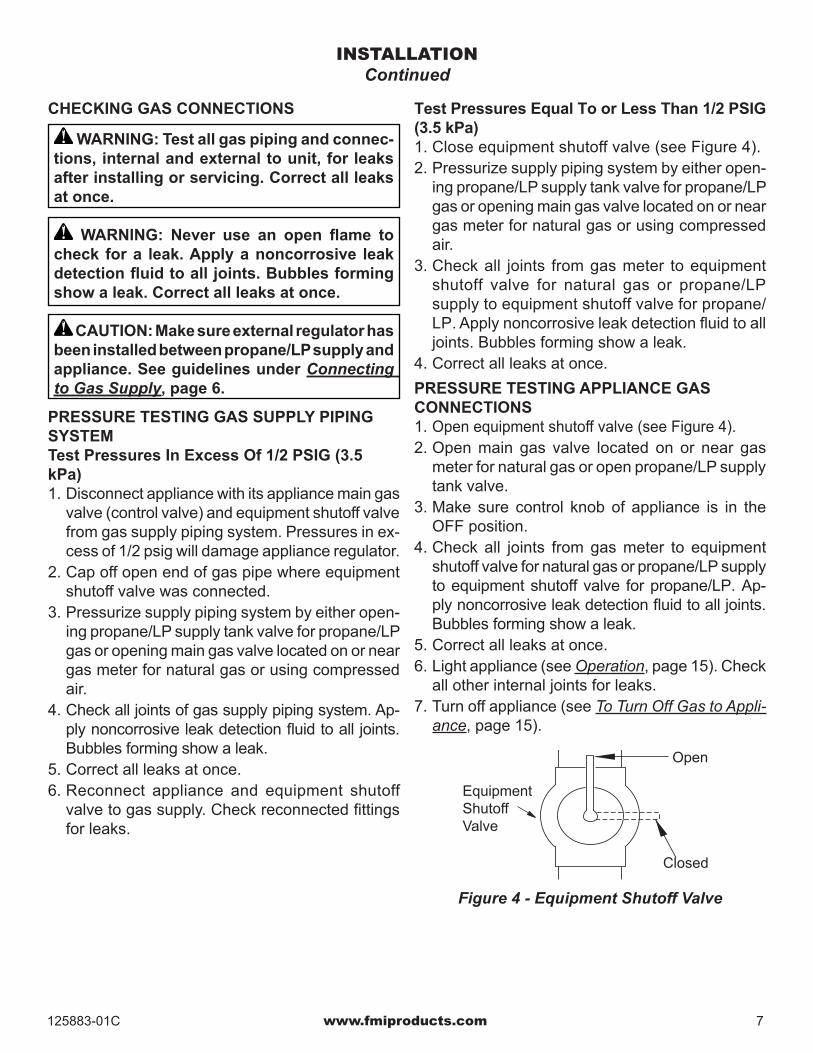
Test Pressures Equal To or Less Than 1/2 PSIG (3.5 kPa)1. Close equipment shutoff valve (see Figure 4).2. Pressurize supply piping system by either open-
ing propane/LP supply tank valve for propane/LP gas or opening main gas valve located on or near gas meter for natural gas or using compressed air.
3. Check all joints from gas meter to equipment shutoff valve for natural gas or propane/LP supply to equipment shutoff valve for propane/LP. Apply noncorrosive leak detection fluid to all joints. Bubbles forming show a leak.
4. Correct all leaks at once.PRESSURE TESTING APPLIANCE GAS CONNECTIONS1. Open equipment shutoff valve (see Figure 4).2. Open main gas valve located on or near gas
meter for natural gas or open propane/LP supply tank valve.
3. Make sure control knob of appliance is in the OFF position.
4. Check all joints from gas meter to equipment shutoff valve for natural gas or propane/LP supply to equipment shutoff valve for propane/LP. Ap-ply noncorrosive leak detection fluid to all joints. Bubbles forming show a leak.
5. Correct all leaks at once.6. Light appliance (see Operation, page 15). Check
all other internal joints for leaks.7. Turn off appliance (see To Turn Off Gas to Appli-
ance, page 15).
Figure 4 - Equipment Shutoff Valve
Open
Closed
Equipment Shutoff Valve

www.fmiproducts.com 125883-01C8
INSTALLATIONContinued
Figure 6 - Laying First Layer of Blocks
BUILDING FIRE RING
WARNING: Failure to position the parts in accordance with these diagrams or failure to use only parts specifically approved with this appliance may result in property damage or personal injury.
1/8” Head Joint
Figure 7 - Head Joints
GAS LINE PLANNINGThe supply line will need to run vertical through the heat shield in the center of the fire ring up to where you will connect it to the gas regulator using a 1/2" flared flex line (not included). There is a 1" hole in the heat shield for the gas line (See Figure 5).
Figure 5 - Gas Line Planning
1" Hole
Heat Shield
1/2" FlareConnector
1. Locate a flat even surface to build your fire ring. See Specifications page 4 for sizing and Minimum Clearances page 5 when selecting a location.
2. Use 8 blocks to build the first layer (See Figure 6). After laying out all blocks, using a level, verify all the blocks are level. Shim if necessary.
FOR PROPANE/LP ONLY: On the first layer, leave 1/8" head joints between blocks (see Figure 7). Do not grout between blocks. This will allow air space for gas to dissipate and not pool in the event of a gas leak.

www.fmiproducts.com125883-01C 9
INSTALLATIONContinued
Figure 8 - Staggered Blocks
Figure 9 - Top Layer (MM2FR Shown)
Figure 10 - Heat Shield Retaining Brackets(MM2FR Shown)
Figure 11 - Block Cover
Heat Shield Retaining Brackets 3. When starting second layer, stagger blocks to the first layer (see Figure 8). For the MM3FR, use 8 blocks to build the second layer. After laying out all blocks, using a level, verify all the blocks are level. Shim if necessary.
4 When starting the top layer, stagger blocks to the layer below. Use 7 full blocks and one half block to build the top layer (see Figure 9). After laying out all blocks, using a level, verify all the blocks are level. Shim if necessary.
5. Place 4 heat shield retaining brackets (longer of the 2 types of brackets included with the MMFRB Series burner system) on the top layer of blocks in the pattern shown in Figure 10.
6. Place Block cover over open block in the first layer for the MM2FR or the second layer for the MM3FR as shown in Figure 11.

www.fmiproducts.com 125883-01C10
INSTALLATIONContinued
Figure 12 - Installing Heat Sheild(MM2FR Shown)
Figure 13 - Burner Retaining Brackets (MM2FR Shown)
Figure 14 - Burner System (MM2FR Shown)
Figure 15 - Lava Retaining Bracket (MM2FR Shown)
WARNING: Heat shield must be installed.
7. Place heat shield on the retaining brackets in the center of the fire ring (see Figure 12).
8. Place 4 burner retaining brackets (shorter of the 2 types of brackets included with the MMFRB Series burner system) on the top layer of blocks in the pattern shown in Figure 13.
Heat Shield
Burner Retaining Brackets
9. Connect incoming gas line to regulator shown in Figure 5 page 8 before placing burner system into place.
10. Place burner system on the retainer brackets in the center of the fire ring with the controls going through the opening in the blocks (see Figure 14). DO NOT GRASP BURNER SYSTEM BY BURNER TUBES.
11. Place lava retaining bracket as shown in Figure 15.
Controls
Lava Retaining
Bracket

www.fmiproducts.com125883-01C 11
INSTALLATIONContinued
12. Place concrete cap on the top layer of blocks. Center cap on block. Level and shim if neces-sary (See Figure 16).
13. Insert access door into hole as shown in Figure 17.
Figure 16 - Concrete Cap (MM2FR Shown)
Figure 17 - Access Door (MM2FR Shown)
INSTALLING LAVA ROCKLava rock comes with the burner system in two boxes each weighing around 42 pounds. Lava rocks range in size. Begin by placing the smaller rocks between the burner tubes filling the whole pan in a single layer of rocks. Avoid placing rocks on the pilot shield. They will obstruct the view of the pilot when you go to light the pilot. You may want to light the pilot first before adding the lava rock (see Lighting Instructions, page 12). Place larger rocks in a second layer in a smaller circle in the center of the fire ring. Lastly place the largest rocks in the center making a teepee formation.

www.fmiproducts.com 125883-01C12
OPERATION
FOR YOUR SAFETY READ BEFORE LIGHTING
WARNING: Keep flue open when operating unit.
WARNING: If you do not follow these instruc-tions exactly, a fire or explosion may result causing property damage, personal injury or loss of life.
A. This appliance has a pilot which must be lighted by hand. When lighting the pilot, follow these instructions exactly.
B. BEFORE LIGHTING smell all around the ap-pliance area for gas. Be sure to smell next to the floor because some gas is heavier than air and will settle on the floor.
WHAT TO DO IF YOU SMELL GAS• Do not try to light any appliance.• Do not touch any electric switch; do not use any phone in your building.
• Immediately call your gas supplier from a neighbor’s phone. Follow the gas supplier’s instructions.
• If you cannot reach your gas supplier, call the fire department.
C. Use only your hand to push in or turn the gas control knob. Never use tools. If the knob will not push in or turn by hand, don’t try to repair it, call a qualified service technician or gas supplier. Force or attempted repair may result in a fire or explosion.
D. Do not use this appliance if any part has been under water. Immediately call a qualified ser-vice technician to inspect the appliance and to replace any part of the control system and any gas control which has been under water.
Ignitor
Figure 18 - Ignitor and Control Knob
Pilot Burner
Thermocouple
Pilot
FROM "PILOT" POSITIONSLIGHT PUSH TO
TURN OFF PULL PUSH
ON
ON
FRO
M "P
ILOT" P
OS
ITION
SLIG
HT P
US
H TO
TU
RN
OFF
PU
LL PU
SH
FRO
M "P
ILO
T" P
OS
ITIO
NS
LIG
HT
PU
SH
TO
TU
RN
OFF
P
ULL
PU
SH
ON
OFF
On OffOFF
OFF
Figure 19 - Thermocouple and Pilot
Control Knob
5. Turn control knob counterclockwise to the PILOT position and press in. Keep control knob pressed in for five (5) seconds.
Note: You may be running this fire ring for the first time after hooking up to gas supply. If so, the control knob may need to be pressed in for 30 seconds or more. This will allow air to bleed from the gas system.• If control knob does not pop up when released, contact a qualified service person or gas sup-plier for repairs.
6. With control knob pressed in, push down and hold ignitor button until pilot is lit. Visually locate the pilot on the control valve cover by the edge of the burner pan to look for flame. If needed, keep pressing ignitor button until pilot lights.
Note: If the pilot will not stay lit after several tries, turn the gas control knob to OFF and call your service technician or gas supplier.
7. Keep control knob pressed in for 30 seconds after lighting pilot. After 30 seconds, release control knob.
Note: If pilot goes out, repeat steps 3 through 7. 8. Turn control knob counterclockwise to the
ON position. Burner should light. If burner does not light, call a qualified service person.
9. To leave pilot lit and shut off burners only, turn control knob clockwise to the PILOT position.
LIGHTING INSTRUCTIONS
1. STOP! Read the safety information.2. Make sure equipment shutoff valve is fully open.3. Press in and turn control knob clockwise to
the OFF position.4. Wait five (5) minutes to clear out any gas. Then
smell for gas, including near the floor. If you smell gas, STOP! Follow “B” in the safety information, column 1. If you don’t smell gas, go to the next step.

www.fmiproducts.com125883-01C 13
OPERATIONContinued
TO TURN OFF GAS TO APPLIANCE
1. Turn control knob clockwise to the PILOT position.
2. Press in and turn control clockwise to the OFF position.
3. Close equipment shutoff valve (see Figure 4, page 7).
CURINGDuring 2-3 hour appliance break-in period, you may detect an odor from the appliance as various paints and compounds used in manu-facturing of this fire ring. This is a normal and temporary situation that is not cause for alarm. To ensure proper curing:• Ignite a 2" flame and maintain it for 1 hour.• Burn in consecutive 1 hour periods raising
flame an additional 2" to full flame height for a total of three hours.
INSPECTING BURNERS
Figure 20 - Pilot Assembly
Figure 21 - Location of the Pilot Adjustment Screw
Thermocouple
Pilot
Check pilot flame pattern and burner flame patterns often.PILOT ASSEMBLYThe pilot assembly is factory preset for proper flame height. Alterations may have occurred during ship-ping and handling. The pilot is located underneath the pilot shield on the burner pan.The thermocouple should be fully enveloped in flame. The flame should not be lifting off of ther-mocouple element.If your pilot assembly does not meet these require-ments:• Access pilot adjustment screw through slot in
valve cover. Turn adjustment screw clockwise to decrease or counterclockwise to increase the flame to proper size (see Figure 21). Do not re-move adjustment screw.
• See Troubleshooting, page 15
Pilot Adjustment Screw
BURNER FLAME PATTERNBurner flames will be steady, not lifting or floating. Flames should go up through middle of the fire ring burner in a tee pee formation.
Electronic Ignitor

www.fmiproducts.com 125883-01C14
CLEANING AND MAINTENANCE
Figure 22 - Injector Holder On Outlet Burner Tube
Burner Tube
Injector Holder
Primary Air Inlet Holes
Figure 23 - Pilot Inlet Air Hole (Your pilot may vary from pilot shown)
WARNING: Turn off appliance and let cool before cleaning.
CAUTION: You must keep control areas, burners and circulating air passageways of ap-pliance clean. Inspect these areas of appliance before each use. Have appliance inspected yearly by a qualified service person.
WARNING: Failure to keep the primary air opening(s) of the burner(s) clean may result in sooting and property damage.
BURNER INJECTOR HOLDER AND PILOT AIR INLET HOLEThe primary air inlet holes allow the proper amount of air to mix with the gas. This provides a clean burning flame. Keep these holes clear of dust, dirt, leaves, lint and pet hair. Clean these air inlet holes prior to each heating season. Blocked air holes will create soot. We recommend that you clean the unit every three months during operation and have appliance inspected yearly by a qualified service person. We also recommend that you keep the burner tube and pilot assembly clean and free of dust and dirt. To clean these parts we recommend using compressed air no greater than 30 PSI. Your local computer store, hardware store or home center may carry compressed air in a can. If using compressed air in a can, please follow the directions on the can. If you don’t follow directions on the can, you could damage the pilot assembly.1. Shut off unit, including pilot. Allow unit to cool for
at least thirty minutes.2. Inspect burner, pilot and primary air inlet holes
on injector holder for dust and dirt (see Figure 22).
3. Blow air through the ports/slots and holes in the burner.
4. Check injector holder located at end of burner tube again. Remove any large particles of dust, dirt, lint or pet hair with a soft cloth or vacuum cleaner nozzle.
5. Blow air into the primary air holes on the injector holder.
6. In case any large clumps of dust have now been pushed into the burner repeat steps 3 and 4.
Clean pilot assembly also. Additional cleaning may be needed for proper pilot operation based on use/lack of use. A yellow tip on the pilot flame may indicate dust and dirt in the pilot assembly. There is a small pilot air inlet hole about from where the pilot flame comes out of pilot assembly (see Figure 23). With unit off, lightly blow air through air inlet hole. You may blow through a drinking straw if com-pressed air is not available.MAIN BURNERPeriodically inspect all burner flame holes with appli-ance running. All slotted burner flame holes should be open with flame present. All round burner flame holes should be open with a small blue flame present. Some burner flame holes may become blocked by debris or rust, with no flame present. If so, turn off appliance and let cool. Remove blockage, blocked burner flame holes will create soot.
WARNING: The injector holders (air shut-ters) are not adjustable. Do not move injector holders from their original positions.
Pilot Burner
Thermocouple

www.fmiproducts.com125883-01C 15
TROUBLESHOOTING
WARNING: Turn off appliance and let cool before servicing. Only a qualified service person should service and repair appliance.
Note: All troubleshooting items are listed in order of operation.
POSSIBLE CAUSE1. Ignitor electrode not con
nected to ignitor cable2. Ignitor cable pinched or wet
3. Broken ignitor cable4. Bad ignitor5. Ignitor electrode positioned
wrong6. Ignitor electrode broken7. Battery not installed, battery
power low or battery not installed correctly
1. Gas supply turned off or equipment shutoff valve closed
2. Control knob not in PILOT position
3. Control knob not pressed in while in PILOT position
4. Air in gas lines when installed
5. Pilot adjustment screw closed
6. Pilot is clogged
7. Low gas pressure
REMEDY 1. Reconnect ignitor cable
2. Free ignitor cable if pinched by any metal or tubing. Keep ignitor cable dry
3. Replace ignitor cable4. Replace ignitor 5. Replace pilot assembly
6. Replace pilot assembly7. Install new alkaline battery
in electronic ignitor. Verify battery is installed correctly
1. Turn on gas supply or open equipment shutoff valve
2. Turn control knob to PILOT position
3. Press in control knob while in PILOT position
4. Continue holding down control knob. Repeat ignit-ing operation until air is removed
5. Adjust pilot flame for ap-proximately 2" blue flame
6. Clean pilot (see Cleaning and Maintenance, page 14) or replace pilot assembly
7. Replace gas control
OBSERVED PROBLEMWhen ignitor button is pressed, there is no spark at pilot
When ignitor button is pressed, there is spark at pilot but no ignition

www.fmiproducts.com 125883-01C16
POSSIBLE CAUSE1. Control knob not fu l ly
pressed in2. Control knob not pressed in
long enough3. Equipment shutoff valve not
fully open4. Pilot flame not touching
thermocouple, which allows thermocouple to cool, caus-ing pilot flame to go out. This problem could be caused by one or both of the following:
A) Low gas pressure B) Dirty or partially clogged
pilot 5. Thermocouple connection
loose at control valve 6. Thermocouple damaged7. Control valve damaged
1. Inlet gas pressure is too low2. Burner orifice clogged
3. Thermocouple leads dis-connected or improperly connected.
4. Burner orifice diameter is too small
1. Pilot flame needs adjusting
2. Wrong pilot orifice
1. Incorrect gas supply or pres-sure
2. Blocked burner orifice or burner manifold ports
3. Improper burner orifice size
REMEDY 1. Press in control knob fully
2. After pilot lights, keep control knob pressed in 30 seconds
3. Fully open equipment shut-off valve
4. A) Contact local natural or propane/LP gas company
B) Clean pilot (see Cleaning and Maintenance, page 14) or replace pilot assembly
5. Hand tighten until snug, then tighten 1/4 turn more
6. Replace thermocouple7. Replace control valve
1. Contact local natural or pro-pane/LP gas company
2. Clean burner (see Cleaning and Maintenance, page 14)
3. Reconnect leads
4. Replace burner orifice
1. Adjust pilot flame for ap-proximately 2" blue flame
2. Replace pilot orifice set
1. Check for proper gas supply pressure
2. Free burner orifice and manifold ports of any burrs, paint or other blockage
3. Verify proper burner orifice sizing
OBSERVED PROBLEMPilot lights but flame goes out when control knob is released
Burner does not light after pilot is lit
Delayed ignition of burner
Burner flame is too low or too high
TROUBLESHOOTINGContinued
www.fmiproducts.com125883-01C 17
TROUBLESHOOTINGContinued
POSSIBLE CAUSE1. Passage of air/gas across
irregular surfaces2. Excessive flame impinge-
ment or blockage
1. Gas leak. See Warning at top of page
2. Control Valve defective
1. Gas leak. See Warning at top of page
1. Metal expanding while heat-ing or contracting while cooling
REMEDY 1. Relieve any tight bends or
kinks in gas supply line2. Check/reset gas regulator
pressure
1. Locate and correct all leaks (See Checking Gas Con-nections, page 7)
2. Replace control valve
1. Locate and correct all leaks (See Checking Gas Con-nections, page 7)
1. This is normal. If noise is excessive, contact qualified service person
OBSERVED PROBLEMBurner is excessively noisy (Note: The movement and com-bustion of gas will create low, unavoidable levels of noise.)
Gas odor even when control knob is in OFF position
Gas odor during combustion
Fire ring produces a clicking/ticking noise just after burner is lit or shuts off
WARNING: If you smell gas• Shut off gas supply.• Do not try to light any appliance.• Do not touch any electrical switch; do not use any phone in your building.• Immediately call your gas supplier from a neighbor’s phone. Follow the gas supplier’s instructions.• If you cannot reach your gas supplier, call the fire department.
IMPORTANT: Operating fire ring where impurities in air exist may create odors. Cleaning supplies, paint, paint remover, cigarette smoke, cements and glues, etc., create fumes. These fumes may mix with combustion air and create odors. These odors will disappear over time.

www.fmiproducts.com 125883-01C18
PARTSBURNER MODELS MMFRBNB, MMFRBPB, MMFRBNS, MMFRBPS
3
5
16
2
1521
22
13
20
23
18
26
19
8
6
4
17
24
25
10
7911
14
14
1
12

www.fmiproducts.com125883-01C 19
PARTSThis list contains replaceable parts used in your appliance. When ordering parts, follow the instructions listed under Replacement Parts on page 21 of this manual.
MM
FRBN
BM
MFR
BPB
MM
FRBN
SM
MFR
BPS
KEY NO. PART NO. DESCRIPTION QTY.1 125889-01 Burner - Black • • 1
125889-02 Burner - Stainless • • 12 125887-01 Pan - Black • • 1
125887-02 Pan - Stainless • • 13 125887-03 Pan Burner (Pie Slice) - Black • • 1
125887-04 Pan Burner (Pie Slice) - Stainless • • 14 126001-01 Brace, Pan/Valve Black • • 2
126001-02 Brace, Pan/Valve, Stainless • • 25 125886-01 Pilot Shield - Black • • 1
125886-02 Pilot Shield - Stainless • • 16 901072-01 Ignitor Wire Harness • • • • 17 901069-01 Pilot, NG • • 1
901069-02 Pilot, LP • • 18 116786-01 Male Fitting • • • • 19 901082-01 Regulator, NG • • 1
901082-02 Regulator, LP • • 110 901062-01 Brass Elbow • • • • 111 901068-02 Manual Valve • • • • 112 14399 Brass Elbow • • • • 113 125897-01 Valve Bracket • • 1
125897-02 Valve Bracket • • 114 111435-01 Electronic Ignitor • • • • 115 901079-01 Control Knob • • • • 116 11209 Nut 10-24 Hex • • • • 217 119795-01 Venturi Gasket • • • • 118 112372-08 Venturi • • • • 119 116559-01 Air Shutter • • • • 120 114365-25 Orifice #12 • • 121 114365-26 Orifice #33 • • 122 111824-01 Brass Compression Cap/Sleeve • • • • 123 125895-02 Heat Shield Retaining Bracket • • • • 424 125895-01 Burner Retaining Bracket • • • • 425 125884-01 Lava Rock Retaining Bracket • • • • 126 125896-01 Heat Shield • • • • 1
PARTS AVAILABLE — NOT SHOWN125965-01 Aluminum Tubing • • • • 1125978-01 Lava Rock Kit (42.5 Lbs) • • • • 2901042-01 Control Knob Decal • • • • 1

www.fmiproducts.com 125883-01C20
PARTSFIRE RING MODELS MM2FR, MM3FR, MM2FRL AND MM3FRLThis list contains replaceable parts used in your appliance. When ordering parts, follow the instructions listed under Replacement Parts on page 21 of this manual.
CONCRETE CAP 125868-01MM2FR & MM3FR - QUANITY 4
BLOCK 125865-01MM2FR - QUANITY 15MM3FR - QUANITY 23
126371-01MM2FRL - QUANITY 15MM3FRL - QUANITY 23
HALF BLOCK 125869-01MM2FR & MM3FR - QUANITY 1
126372-01MM2FRL & MM3FRL - QUANITY 1
BLOCK COVER 125957-03MM2FR & MM3FR - QUANITY 1MM2FRL & MM3FRL - QUANITY 1
ACCESS DOOR INCLUDING RING, NUT & WASHER 125888-01MM2FR & MM3FR - QUANITY 1ACCESS DOOR INCLUDING RING, NUT & WASHER (LEDGE STONE) 125888-02MM2FRL & MM3FRL - QUANITY 1DOOR HANDLE ASSY 111454-02MM2FR & MM3FR - QUANITY 1MM2FRL & MM3FRL - QUANITY 1WASHER 7/16ID X 1.00" 111456-01MM2FR & MM3FR - QUANITY 1MM2FRL & MM3FRL - QUANITY 1NUT 3/8-16 HEX NUT 111457-01MM2FR & MM3FR - QUANITY 1MM2FRL & MM3FRL - QUANITY 1

www.fmiproducts.com125883-01C 21
REPLACEMENT PARTSNote: Use only original replacement parts. This will protect your warranty coverage for parts replaced under warranty.Contact authorized dealers of this product. If they can’t supply original replacement part(s), call FMI PRODUCTS, LLC at 1-866-328-4537.When calling, have ready:• your name• your address• model and serial numbers of your appliance• how appliance was malfunctioning• purchase dateUsually, we will ask you to return the part to the factory.
SERVICE HINTSWhen Gas Pressure Is Too Low• pilot will not stay lit• burners will have delayed ignition• appliance will not produce specified heat• propane/LP gas supply may be lowYou may feel your gas pressure is too low. If so, contact your local propane/LP or natural gas supplier.
TECHNICAL SERVICEYou may have further questions about installation, operation or troubleshooting. If so, contact FMI PRODUCTS, LLC at 1-866-328-4537. When call-ing please have your model and serial numbers of your appliance ready.You can also visit our web site at www.fmiproducts.com.

www.fmiproducts.com 125883-01C22
_________________________________________________________________________________________________________________________________________________________________________________________________________________________________________________________________________________________________________________________________________________________________________________________________________________________________________________________________________________________________________________________________________________________________________________________________________________________________________________________________________________________________________________________________________________________________________________________________________________________________________________________________________________________________________________________________________________________________________________________________________________________________________________________________________________________________________________________________________________________________________________________________________________________________________________________________________________________________________________________________________________________________________________________________________________________________________________________________________________________________________________________________________________________________________________________________________________________________________________________________________________________________________________________________________________________________________________________________________________________________________________________________________________________________________________________________________________________________________________________________________________________________________________________________________________________________________________________________________________________________________________________________________________________________________________________________________________________________________________________________________________________________________________________________________________________________________________________________________________________________________________________________________________________________________________________________________________________________________________________________________________________________________________________________________________________________________________________________________________________________________________________________________________________________________________________________________________________________________________________________
NOTES

www.fmiproducts.com125883-01C 23
_________________________________________________________________________________________________________________________________________________________________________________________________________________________________________________________________________________________________________________________________________________________________________________________________________________________________________________________________________________________________________________________________________________________________________________________________________________________________________________________________________________________________________________________________________________________________________________________________________________________________________________________________________________________________________________________________________________________________________________________________________________________________________________________________________________________________________________________________________________________________________________________________________________________________________________________________________________________________________________________________________________________________________________________________________________________________________________________________________________________________________________________________________________________________________________________________________________________________________________________________________________________________________________________________________________________________________________________________________________________________________________________________________________________________________________________________________________________________________________________________________________________________________________________________________________________________________________________________________________________________________________________________________________________________________________________________________________________________________________________________________________________________________________________________________________________________________________________________________________________________________________________________________________________________________________________________________________________________________________________________________________________________________________________________________________________________________________________________________________________________________________________________________________________________________________________________________________________________________________________________
NOTES
125883-01Rev. C15/12
WARRANTYKEEP THIS WARRANTY
FMI PRODUCTS, LLC LIMITED WARRANTIESNew Products
Standard Warranty: FMI PRODUCTS, LLC warrants this new product and any parts thereof to be free from defects in ma-terial and workmanship for a period of four (4) years from the date of first purchase from an authorized dealer provided the product has been installed, maintained and operated in accordance with FMI PRODUCTS, LLC’s warnings and instructions.For products purchased for commercial, industrial or rental usage, this warranty is limited to 90 days from the date of first purchase.
Factory Reconditioned ProductsLimited Warranty: FMI PRODUCTS, LLC warrants factory reconditioned products and any parts thereof to be free from defects in material and workmanship for 30 days from the date of first purchase from an authorized dealer provided the product has been installed, maintained and operated in accordance with FMI PRODUCTS, LLC’s warnings and instructions.
Terms Common to All WarrantiesThe following terms apply to all of the above warranties:Always specify model number and serial number when contacting the manufacturer. To make a claim under this warranty the bill of sale or other proof of purchase must be presented.This warranty is extended only to the original retail purchaser when purchased from an authorized dealer, and only when installed by a qualified installer in accordance with all local codes and instructions furnished with this product.This warranty covers the cost of part(s) required to restore this product to proper operating condition and an allowance for labor when provided by a FMI PRODUCTS, LLC Authorized Service Center or a provider approved by FMI PRODUCTS, LLC. Warranty parts must be obtained through authorized dealers of this product and/or FMI PRODUCTS, LLC who will provide original factory replacement parts. Failure to use original factory replacement parts voids this warranty.Travel, handling, transportation, diagnostic, material, labor and incidental costs associated with warranty repairs, unless expressly covered by this warranty, are not reimbursable under this warranty and are the responsibility of the owner.Excluded from this warranty are products or parts that fail or become damaged due to misuse, accidents, improper instal-lation, lack of proper maintenance, tampering, or alteration(s).This is FMI PRODUCTS, LLC’s exclusive warranty, and to the full extent allowed by law; this express warranty excludes any and all other warranties, express or implied, written or verbal and limits the duration of any and all implied warranties, including warranties of merchantability and fitness for a particular purpose to four (4) years on new products and 30 days on factory reconditioned products from the date of first purchase. FMI PRODUCTS, LLC makes no other warranties regarding this product.FMI PRODUCTS, LLC’s liability is limited to the purchase price of the product, and FMI PRODUCTS, LLC shall not be li-able for any other damages whatsoever under any circumstances including indirect, incidental, or consequential damages.Some states do not allow limitations on how long an implied warranty lasts or the exclusion or limitation of incidental or consequential damages, so the above limitation or exclusion may not apply to you. This warranty gives you specific legal rights, and you may also have other rights which vary from state to state. For information about this warranty contact:
Model (located on product or identification tag) ��������������������������������������Serial No. (located on product or identification tag) �����������������������������������
Date Purchased ��������������������������������������������Keep receipt for warranty verification.
2701 S. Harbor Blvd.Santa Ana, CA 92704
1-866-328-4537www.fmiproducts.com