Embed Size (px)
Citation preview
Fire Protection FPS-13
Fire protectionsolutions

Eaton and Cooper united.
Energizing a worldthat demands more.
Powering business worldwideAs a global diversifi ed power management company, we help customers worldwide manage the power needed for buildings, aircraft, trucks, cars, machinery and businesses.
Eaton’s innovative technologies help customers manage electrical, hydraulic and mechanical power more reliably, effi ciently, safely and sustainably.
Discover today’s Eaton.

Eaton’s electrical businessEaton is a global leader with expertise in:• Power distribution and circuit protection
• Backup power protection
• Solutions for harsh and hazardous environments
• Lighting and security
• Structural solutions and wiring devices
• Control and automation
• Engineering services
We deliver:• Electrical solutions that use less energy, improve power reliability
and make the places we live and work safer and more comfortable
• Hydraulic and electrical solutions that enable machines to deliver more productivity without wasting power
• Aerospace solutions that make aircraft lighter, safer and less costly to operate, and help airports operate more efficiently
• Vehicle drivetrain and powertrain solutions that deliver more power to cars, trucks and buses, while reducing fuel consumption and emissions
We provide integrated
solutions that help make
energy, in all its forms,
more practical and
accessible.
With 2012 sales of
$16.3 billion, Eaton
has approximately
103,000 employees
around the world and
sells products in more
than 175 countries.
Eaton is positioned through its global solutions to answer today’s most critical electrical power management challenges. With 100 years of electrical experience behind us, we’re energized by the challenge of powering up a world that demands twice as much energy as today. We’re anticipating needs, engineering products, and creating solutions to energize our markets today and in the future.
We are dedicated to ensuring that reliable, efficient and safe power is available when it’s needed most.
Eaton.com

Main Office Fire Protection Customer Service
Eaton’s B-Line Business Eaton’s B-Line Business509 West Monroe Street 1375 Sampson AvenueHighland, Illinois 62249-0326 Corona, CA 92879Phone: 800-851-7415 Phone: 951-737-5599Fax: 618-654-1917 Fax: 951-737-0330
www.cooperbline.com/fireprotection
Manufacturers Standardization Societyof the Valve and Fitting Industry, Inc.
For over 45 years, the TOLCO™ brand has been synonymous with innovative, labor saving pipe hanger andseismic bracing solutions for the fire protection industry.
Products & Services
• TolBrace™ Seismic Bracing Software• One of the broadest lines of pipe hangers, strut and seismic bracing in the industry
Fire Protection TeamOur Fire Protection team actively participates in the fire protection industry, including:
• Membership in the NFPA Technical Committee on Hanging and Bracing of Water Based AutomaticFire Sprinkler Systems
• MSS 403 Standards Committee for Pipe Hanging and Seismic Bracing
Product CertificationsMany of the products shown in this catalog are certified with the following:
• Listed by Underwriters Laboratories (UL) in U.S. and Canada• Factory Mutual Engineering Approved (FM) • Pre-approved by the State of California, Office of Statewide Health, Planning and Development
(OSHPD) as shown in our OPA-0300 Seismic Bracing Guidelines
Our Fire Protection Solutions catalog is intended to aid design engineers, specifying engineers, AuthoritiesHaving Jurisdiction (AHJs) and others seeking solutions to their pipe support and seismic bracing systeminstallations and design challenges.
For more information on B-Line pipe hangers and supports, and TOLCO seismic bracing solutions utilized inother applications, such as mechanical or plumbing systems, please refer to our Pipe Hangers & Supportsand Strut Systems catalogs, and the State of California OSHPD Pre-Approved Seismic Restraint GuidelinesOPA-0300. These resources and other valuable information can be found online at www.bline.com.
NOTICEEaton’s B-Line Business reserves the right to change the specifications, materials, equipment, pricesor the availability of products at any time without prior notice. While every effort has been made toassure the accuracy of information contained in this catalog at the time of publication, we are notresponsible for inaccuracies resulting from undetected errors or omissions.
ISO 9001:2008
Introduction
Fire Protection Solutions
BracketsLight Duty .................................................................................... 80Medium Duty ............................................................................ 81Brackets with U-Bolts ....................................................... 82
Upper Attachments Ceiling Flange ........................................................................... 83Angle Supports ............................................................ 83 - 85Swivel Attachment .............................................................. 86Bolted & Welded Clevis ................................................... 87Concrete Plates ............................................................ 88 - 89
Threaded Accessories Eye Nuts ........................................................................................ 90U-Bolts ................................................................................. 91 - 93Rods, Rod Stiffeners, Couplings, Washers & Hardware .................................... 94 - 103
Reference DataMetric Conversions ............................................ 104 - 105Miscellaneous ChartsPiping, Tubing, Threaded Rod, etc. ..... 106 - 110Beam Data Charts ............................................... 111 - 113Trapeze Hanger Chart ...................................... 114 - 115MSS & Federal Specification Charts .. 116 - 117B-Line Compliances & Approvals .......... 118 - 119
Cross ReferencesTOLCO to B-Line ................................................... 120 - 121B-Line to TOLCO ................................................... 122 - 123Anvil/Grinnell®† to B-Line/TOLCO ........................ 124Erico®† to B-Line/TOLCO ............................................... 125PHD®† to B-Line/TOLCO ................................................. 126Super Strut®† to B-Line/TOLCO .............................. 127C & P®† to B-Line/TOLCO .................................................. 128Empire®† to B-Line/TOLCO .......................................... 129
Index ................................................................... 130
† Mark shown in this document is the property of its respective owner.
Fire Protection Information .................................................. 2
Application Photos ....................................................................... 3
Pictorial Index ............................................................................ 4 - 9
Beam Clamps C-Clamps ............................................................................ 10 - 15Retaining Straps ......................................................... 16 - 17Bar Joist Hanger .................................................................... 18Composite Wood Joist Clamp .................................. 19
Pipe Hangers Clevis Hangers - NFPA ..................................................... 20Band Hangers ................................................................ 21 - 24Split Clamps ............................................................................... 25‘U’ Hangers ...................................................................... 26 - 28
Pipe Clamps Risers ................................................................................................ 29Underground Clamps ............................................. 30 - 31Clamps ................................................................................. 32 - 33Straps ............................................................................................... 34CPVC Hangers & Surge Restrainers .......... 35 - 43
Pipe Supports Stands .................................................................................. 44 - 45Supports ............................................................................. 46 - 47
Seismic BracingSwivel Attachment & Rod Stiffeners ................. 48Sway Bracing Pipe Clamps .......................................... 49Sway Brace Main Pipe Attachments ........ 50 - 72
Concrete InsertsConcrete Deck Inserts ............................................ 74 - 75Spot Inserts & Insert Nuts ................................. 76 - 79
Table of Contents
1Fire Protection Solutions
Fire ProtectionInform
ation
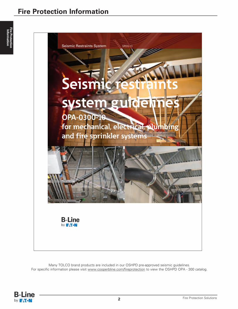
Many TOLCO brand products are included in our OSHPD pre-approved seismic guidelines.For specific information please visit www.cooperbline.com/fireprotection to view the OSHPD OPA - 300 catalog.
Seismic Restraints System SRSG-13
Seismic restraintssystem guidelinesOPA-0300-10for mechanical, electrical, plumbingand fire sprinkler systems
Fire Protection Information
Fire Protection Solutions2

Application Photos
TOLBrace™
3Fire Protection Solutions
TOLBrace Fire ProtectionSoftware
Allows you to create a submittal sheet, withall relevant information, at the click of a mouse!
TOLBrace™ 7.0 includes a feature that will automaticallyupdate your software, via the internet, when newproducts are added; when there are updates to codesand standards, and any necessary software upgrades.
TOLBrace software assists a Fire Sprinkler systemdesigner with the following:
• Seismic force factor calculations (Fp)• Zone of influence calculations• Sway brace orientation and angle selection• Structural attachment of sway braces• Brace material selection• Appropriate selection of UL Listed and FM Approved sway brace components• Creating a submittal sheet with all relevant information with the click of a mouse!
TOLBrace follows the requirements of:
• NFPA 13, 1999, 2002, 2007 & 2010• Uniform Building Code• International Building Code• National Building Code of Canada• California Office of Statewide Health Planning & Development (OSHPD)
Seismic Bracing Services & Products for Mechanical, Electrical and Plumbing Systems
In addition to our long reputation as a provider of sway bracing products and software for the Fire Sprinkler Industry, we also provides a line of products and services directed to theinstallers of all other non-structural building systems. We provide:
• Pre-project bid assistance to contractors• Assist building owner, architect and design engineer with code compliance and design questions• Review and updates to product specifications• Pre-Approved (OSHPD) and/or Project Specific Engineered• Seismic Restraint Details• Layout of Seismic Restraints on Project Drawings• Product in "kit" or "bulk" shipments to meet all project management and budget requirements• Installer training• Post installation jobsite inspection
For more information, visit www.cooperbline.com/tolbrace.
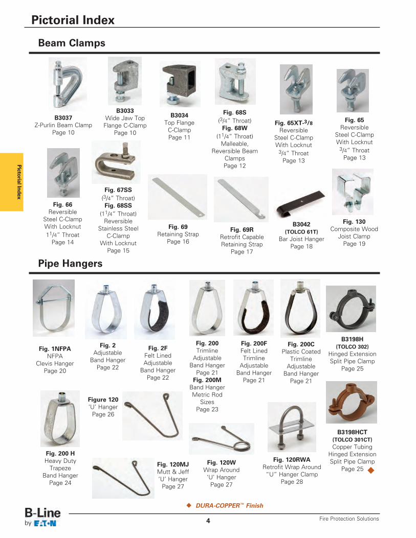
Pictorial Index
Beam Clamps
Pipe Hangers
Fig. 130Composite Wood
Joist ClampPage 19
B3042(TOLCO 61T)
Bar Joist HangerPage 18
Fig. 69RRetrofit CapableRetaining Strap
Page 17
Fig. 69Retaining Strap
Page 16
Fig. 67SS(3/4” Throat)Fig. 68SS
(11/4” Throat)Reversible
Stainless SteelC-Clamp
With LocknutPage 15
Fig. 65XT-3/8Reversible
Steel C-ClampWith Locknut
3/4” ThroatPage 13
Fig. 65Reversible
Steel C-ClampWith Locknut
3/4” ThroatPage 13
Fig. 66Reversible
Steel C-ClampWith Locknut11/4” Throat
Page 14
B3033Wide Jaw Top
Flange C-ClampPage 10
B3034Top Flange
C-ClampPage 11
B3037Z-Purlin Beam Clamp
Page 10
u DURA-COPPER™ Finish
Fig. 1NFPANFPA
Clevis HangerPage 20
B3198H(TOLCO 302)
Hinged ExtensionSplit Pipe Clamp
Page 25
B3198HCT(TOLCO 301CT)Copper Tubing
Hinged ExtensionSplit Pipe Clamp
Page 25 u
Fig. 200 HHeavy Duty
TrapezeBand Hanger
Page 24
Fig. 200Trimline
AdjustableBand Hanger
Page 21Fig. 200M
Band HangerMetric Rod
SizesPage 23
Fig. 200FFelt LinedTrimline
AdjustableBand Hanger
Page 21
Fig. 200CPlastic Coated
TrimlineAdjustable
Band HangerPage 21
Figure 120‘U’ Hanger
Page 26
Fig. 120MJMutt & Jeff‘U’ Hanger
Page 27
Fig. 120RWARetrofit Wrap Around“U” Hanger Clamp
Page 28
Fig. 120WWrap Around‘U’ Hanger
Page 27
Pictorial Index
Fire Protection Solutions4
Fig. 68S(3/4” Throat)Fig. 68W
(11/4” Throat)Malleable,
Reversible BeamClampsPage 12
Fig. 2FFelt LinedAdjustable
Band HangerPage 22
Fig. 2Adjustable
Band HangerPage 22
Pictorial Index
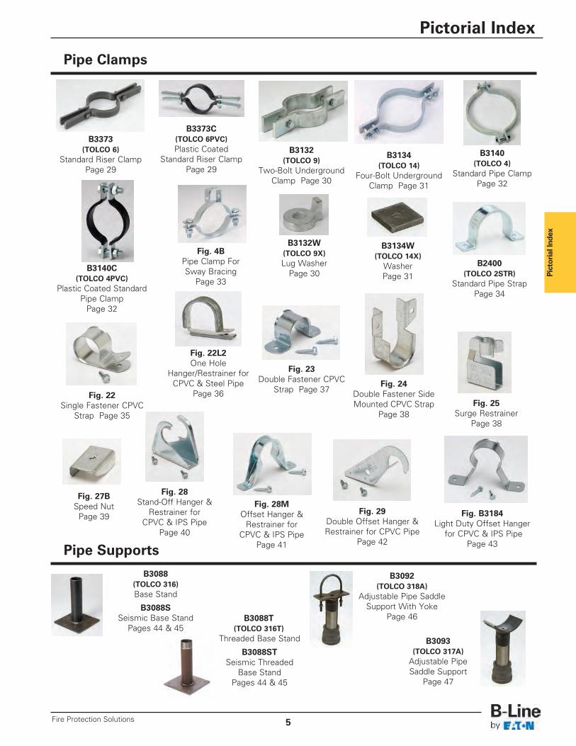
Pipe Clamps
Pipe Supports
B3140(TOLCO 4)
Standard Pipe ClampPage 32
B3140C(TOLCO 4PVC)
Plastic Coated StandardPipe Clamp
Page 32
B3132(TOLCO 9)
Two-Bolt UndergroundClamp Page 30
B3132W(TOLCO 9X)Lug Washer
Page 30
B3134W(TOLCO 14X)
WasherPage 31
B3134(TOLCO 14)
Four-Bolt UndergroundClamp Page 31
B3373C(TOLCO 6PVC)Plastic Coated
Standard Riser ClampPage 29
B3373(TOLCO 6)
Standard Riser ClampPage 29
Fig. 28MOffset Hanger &
Restrainer forCPVC & IPS Pipe
Page 41
Fig. 29Double Offset Hanger &Restrainer for CPVC Pipe
Page 42
Fig. B3184Light Duty Offset Hanger
for CPVC & IPS PipePage 43
Fig. 22Single Fastener CPVC
Strap Page 35
Fig. 23Double Fastener CPVC
Strap Page 37
Fig. 22L2One Hole
Hanger/Restrainer forCPVC & Steel Pipe
Page 36Fig. 24
Double Fastener SideMounted CPVC Strap
Page 38Fig. 25
Surge RestrainerPage 38
Fig. 27BSpeed NutPage 39
Fig. 28Stand-Off Hanger &
Restrainer forCPVC & IPS Pipe
Page 40
B2400(TOLCO 2STR)
Standard Pipe StrapPage 34
B3092(TOLCO 318A)
Adjustable Pipe SaddleSupport With Yoke
Page 46
B3093(TOLCO 317A)
Adjustable PipeSaddle Support
Page 47
B3088(TOLCO 316)Base Stand
B3088SSeismic Base Stand
Pages 44 & 45B3088T
(TOLCO 316T)Threaded Base Stand
B3088STSeismic Threaded
Base StandPages 44 & 45
Pictorial Index
5Fire Protection Solutions
Fig. 4BPipe Clamp ForSway Bracing
Page 33
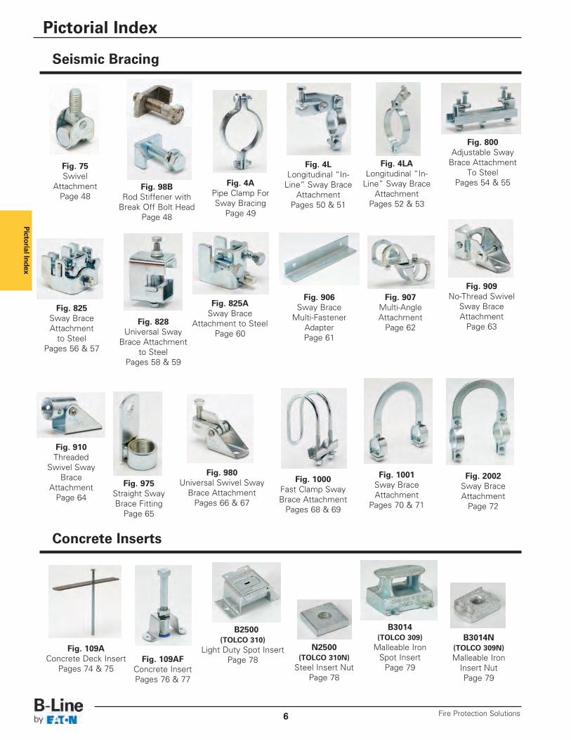
Pictorial Index
Seismic Bracing
Concrete Inserts
Fig. 4APipe Clamp ForSway Bracing
Page 49
Fig. 4LLongitudinal “In-
Line” Sway BraceAttachment
Pages 50 & 51
Fig. 4LALongitudinal “In-
Line” Sway BraceAttachment
Pages 52 & 53
Fig. 800Adjustable Sway
Brace AttachmentTo Steel
Pages 54 & 55
Fig. 825Sway BraceAttachment
to SteelPages 56 & 57
Fig. 828Universal Sway
Brace Attachmentto Steel
Pages 58 & 59
Fig. 825ASway Brace
Attachment to SteelPage 60
Fig. 910Threaded
Swivel SwayBrace
AttachmentPage 64
Fig. 909No-Thread Swivel
Sway BraceAttachment
Page 63
Fig. 907Multi-AngleAttachment
Page 62
Fig. 980Universal Swivel Sway
Brace AttachmentPages 66 & 67
Fig. 975Straight SwayBrace Fitting
Page 65
Fig. 906Sway Brace
Multi-FastenerAdapterPage 61
Fig. 1000Fast Clamp SwayBrace Attachment
Pages 68 & 69
Fig. 1001Sway BraceAttachment
Pages 70 & 71
Fig. 2002Sway BraceAttachment
Page 72
Fig. 109AFConcrete InsertPages 76 & 77
Fig. 109AConcrete Deck Insert
Pages 74 & 75
B2500(TOLCO 310)
Light Duty Spot InsertPage 78
N2500(TOLCO 310N)
Steel Insert NutPage 78
B3014(TOLCO 309)
Malleable IronSpot Insert
Page 79
B3014N(TOLCO 309N)Malleable Iron
Insert NutPage 79
Pictorial Index
Fire Protection Solutions6
Fig. 75Swivel
AttachmentPage 48
Fig. 98BRod Stiffener with
Break Off Bolt HeadPage 48
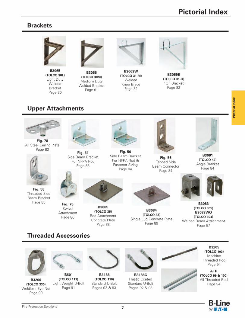
Pictorial Index
Brackets
Upper Attachments
Threaded Accessories
B3061(TOLCO 42)
Angle BracketPage 84
Fig. 78All Steel Ceiling Plate
Page 83Fig. 51
Side Beam BracketFor NFPA Rod
Page 83
Fig. 50Side Beam Bracket
For NFPA Rod &Fastener Sizing
Page 84
Fig. 56Tapped Side
Beam ConnectorPage 84
Fig. 58Threaded SideBeam Bracket
Page 85 Fig. 75Swivel
AttachmentPage 86
B3083(TOLCO 305)B3083WO(TOLCO 304)
Welded Beam AttachmentPage 87
B3085(TOLCO 35)
Rod AttachmentConcrete Plate
Page 88
B3084(TOLCO 33)
Single Lug Concrete PlatePage 89
B501(TOLCO 111)
Light Weight U-BoltPage 91
B3188(TOLCO 110)
Standard U-BoltPages 92 & 93
B3188CPlastic Coated
Standard U-BoltPages 92 & 93
B3200(TOLCO 330)
Weldless Eye NutPage 90
B3205(TOLCO 103)
MachineThreaded Rod
Page 94
ATR(TOLCO 99 & 100)All Threaded Rod
Page 94
B3066(TOLCO 30M)Medium Duty
Welded BracketPage 81
B3065(TOLCO 30L)Light Duty
WeldedBracketPage 80
B3069W(TOLCO 31-M)
WeldedKnee Brace
Page 82
B3069E(TOLCO 31-O)“O” Bracket
Page 82
Pictorial Index
7Fire Protection Solutions
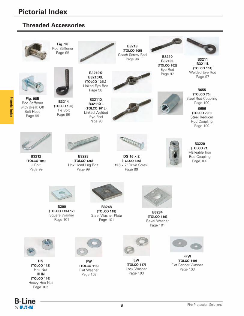
Pictorial Index
Threaded Accessories
B3234(TOLCO 116)
Bevel WasherPage 101
B3248(TOLCO 118)
Steel Washer PlatePage 101
B200(TOLCO F13-F17)Square Washer
Page 101
HN(TOLCO 113)
Hex Nut HHN
(TOLCO 114)Heavy Hex Nut
Page 102
FW(TOLCO 115)Flat Washer
Page 103
FFW(TOLCO 119)
Flat Fender WasherPage 103
LW(TOLCO 117)Lock Washer
Page 103
B3212(TOLCO 104)
J-BoltPage 99
B3228(TOLCO 126)
Hex Head Lag BoltPage 99
DS 16 x 2(TOLCO 125)
#16 x 2" Drive ScrewPage 99
B3220(TOLCO 71)
Malleable IronRod Coupling
Page 100
B3210B3210L
(TOLCO 102)Eye RodPage 97
B3211B3211L
(TOLCO 101)Welded Eye Rod
Page 97B3210XB3210XL
(TOLCO 102L)Linked Eye Rod
Page 98
B3211XB3211XL
(TOLCO 101L)Linked Welded
Eye RodPage 98
Fig. 98BRod Stiffener
with Break OffBolt HeadPage 95
Fig. 98Rod Stiffener
Page 95
B3214(TOLCO 106)
Tie BoltPage 96
B3213(TOLCO 105)
Coach Screw RodPage 96
B655(TOLCO 70)
Steel Rod CouplingPage 100
B656(TOLCO 70R)
Steel Reducer Rod Coupling
Page 100
Pictorial Index
Fire Protection Solutions8
Pictorial Index
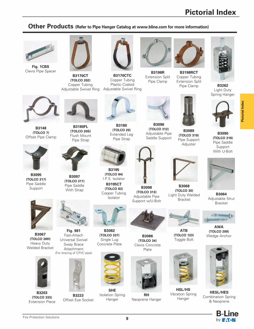
Other Products (Refer to Pipe Hanger Catalog at www.bline.com for more information)
SHEIsolation Spring
Hanger
HSL/HSVibration Spring
HangerRH
Neoprene Hanger
HESL/HESCombination Spring
& Neoprene
ATB(TOLCO 123)Toggle Bolt
AWA(TOLCO 209)
Wedge AnchorB3082
(TOLCO 337)Single Lug
Concrete Plate
B3086(TOLCO 34)
Clevis ConcretePlate
B3223Offset Eye Socket
B3203(TOLCO 333)
Extension Piece
B3148(TOLCO 7)
Offset Pipe Clamp
B3180FL(TOLCO 20S)Flush MountPipe Strap
B3180(TOLCO 20)
Extended LegPipe Strap
B3097(TOLCO 311)Pipe SaddleWith Strap
B3098(TOLCO 313)
Adjustable PipeSupport w/U-Bolt
B3095(TOLCO 317)Pipe Saddle
Support
B3089(TOLCO 319)Pipe Support
Adjuster
B3090(TOLCO 318)Pipe Saddle
SupportWith U-Bolt
B3096(TOLCO 312)
Adjustable PipeSaddle Support
B3195(TOLCO 84)
I.P.S. IsolatorB3195CT(TOLCO 83)
Copper TubingIsolator
B3064Adjustable Strut
Bracket
B3068(TOLCO 30)
Light Duty WeldedBracket
B3067(TOLCO 30H)Heavy Duty
Welded Bracket
Fig. 981Fast-Attach
Universal SwivelSway BraceAttachment
(For bracing of CPVC pipe)
Fig. 1CBSClevis Pipe Spacer
B3170CTCCopper TubingPlastic Coated
Adjustable Swivel Ring
B3170CT(TOLCO 202)
Copper TubingAdjustable Swivel Ring
B3198RExtension Split
Pipe Clamp
B3198RCTCopper TubingExtension Split
Pipe Clamp B3262Light Duty
Spring Hanger
Pictorial Index
9Fire Protection Solutions
Beam
Clam
ps
All dimensions in charts and on drawings are in inches. Dimensions shown in parentheses are in millimeters unless otherwise specified.
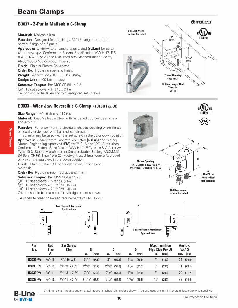
Material: Malleable IronFunction: Designed for attaching a 3/8"-16 hanger rod to thebottom flange of a Z-purlin.Approvals: Underwriters Laboratories Listed (cULus) for up to4” (100mm) pipe. Conforms to Federal Specification WW-H-171E &A-A-1192A, Type 23 and Manufacturers Standardization SocietyANSI/MSS SP-69 & SP-58, Type 23.Finish: Plain or Electro-GalvanizedOrder By: Figure number and finish. Weight: Approx. Wt./100 90 Lbs. (40.8kg)Design Load: 400 Lbs. (1.78kN)
B3037 - Z-Purlin Malleable C-Clamp
Setscrew Torque: Per MSS SP-58 14.2.53/8” -16 set screws = 5 ft./lbs. (7 Nm)Caution should be taken not to over-tighten set screws.
Set Screw andLocknut Included
3"(76.2)
313/32"(86.5)
Throat Opening31/32" (24.6)
Bottom Hanger RodThreads3/8"-16
Size Range: 3/8"-16 thru 3/4"-10 rodMaterial: Cast Malleable Steel with hardened cup point set screwand jam nut
Function: For attachment to structural shapes requiring wider throatespecially under roof with bar joist construction.This clamp may be used with the set screw in the up or down position.Approvals: Underwriters Laboratories Listed (cULus) and FactoryMutual Engineering Approved (FM) for 3/8”-16 and 1/2”-13 rod sizes.Conforms to Federal Specification WW-H-171E Type 19 & A-A-1192A,Type 19 & 23 and Manufacturers Standardization Society ANSI/MSSSP-69 & SP-58, Type 19 & 23. Factory Mutual Engineering Approvedonly with the setscrew in the down position.Finish: Plain. Contact B-Line for alternative finishes and materials.Order By: Figure number, rod size and finishSetscrew Torque: Per MSS SP-58 14.2.53/8” -16 set screws = 5 ft./lbs. (7 Nm)1/2” -13 set screws = 11 ft./lbs. (15 Nm)5/8” -11 set screws = 21 ft./lbs. (28 Nm)Caution should be taken not to over-tighten set screws.
Designed to meet or exceed requirements of FM DS 2-0.
Set Screw andLocknut Included
A(Rod Size)Hanger RodNot Included
B
DC
Throat Opening11/4" (31.7) for B3033-3/8 & 1/215/16" (33.3) for B3033-5/8 & 3/4
B3033 - Wide Jaw Reversible C-Clamp (TOLCO Fig. 68)
Part Rod Set Screw Maximum Iron Approx.No. Size Size B C D Pipe Size Per UL Wt./100
A in. (mm) in. (mm) in. (mm) in. (mm) Lbs. (kg)
B3033-3/8 3/8"-16 3/8"-16 x 2” 21/4" (57.1) 2" (50.8) 11/8" (28.6) 4" (100) 54 (24.5)
B3033-1/2 1/2"-13 1/2"-13 x 21/2” 25/16" (58.7) 23/16" (55.6) 11/4" (31.7) 8" (200) 51 (23.1)
B3033-5/8 5/8"-11 1/2"-13 x 21/2” 25/8" (66.7) 21/2" (63.5) 13/8" (34.9) 8" (200) 70 (31.7)
B3033-3/4 3/4"-10 5/8"-11 x 21/2” 211/16" (68.3) 21/2" (63.5) 17/16" (36.5) 10" (250) 98 (44.4)
Bottom Flange AttachmentApplications
Top Flange AttachmentApplications
Beam Clamps
Fire Protection Solutions10
Beam Clamps
All dimensions in charts and on drawings are in inches. Dimensions shown in parentheses are in millimeters unless otherwise specified.
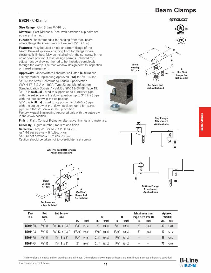
B3034 - C-Clamp
Size Range: 3/8"-16 thru 3/4"-10 rodMaterial: Cast Malleable Steel with hardened cup point setscrew and jam nutFunction: Recommended for hanging from steel beamwhere flange thickness does not exceed 3/4" (19.0mm).Features: May be used on top or bottom flange of thebeam. Beveled lip allows hanging from top flange whereclearance is limited. May be installed with the set screw in theup or down position. Offset design permits unlimited rodadjustment by allowing the rod to be threaded completelythrough the clamp. The rear window design permits inspectionof thread engagement.Approvals: Underwriters Laboratories Listed (cULus) andFactory Mutual Engineering Approved (FM) for 3/8”-16 and1/2”-13 rod sizes. Conforms to Federal SpecificationWW-H-171E & A-A-1192A, Type 23 and ManufacturersStandardization Society ANSI/MSS SP-69 & SP-58, Type 19. 3/8"-16 is (cULus) Listed to support up to 4" (100mm) pipewith the set screw in the down position, up to 3" (75mm) pipewith the set screw in the up position. 1/2"-13 is (cULus) Listed to support up to 8" (200mm) pipewith the set screw in the down position, up to 6" (150mm)pipe with the set screw in the up position.Factory Mutual Engineering Approved only with the setscrewin the down position.Finish: Plain. Contact B-Line for alternative finishes and materials. Order By: Figure number, rod size and finishSetscrew Torque: Per MSS SP-58 14.2.53/8” -16 set screws = 5 ft./lbs. (7 Nm)1/2” -13 set screws = 11 ft./lbs. (15 Nm)Caution should be taken not to over-tighten set screws.
Set Screw andLocknut Included
A(Rod Size)Hanger RodNot Included
B
DC
ThroatOpening3/4" (19.0)
B3034-5/8" and B3034-3/4" sizesAttach only as shown.
Top FlangeAttachmentApplications
Bottom FlangeAttachmentApplications
Set Screw andLocknut Included
A(Rod Size)Hanger RodNot Included
B
DC
ThroatOpening3/4" (19.0)
Part Rod Set Screw Maximum Iron Approx.No. Size Size B C D Pipe Size Per UL Wt./100
A in. (mm) in. (mm) in. (mm) in. (mm) Lbs. (kg)
B3034-3/8 3/8"-16 3/8"-16 x 11/2” 15/8" (41.3) 2" (50.8) 7/8" (19.0) 4" (100) 30 (13.6)
B3034-1/2 1/2"-13 1/2"-13 x 11/2” 113/16" (46.0) 23/16" (55.6) 13/16" (30.2) 8" (200) 47 (21.3)
B3034-5/8 5/8"-11 1/2"-13 x 2” 13/4" (44.5) 21/8" (54.0) 11/4" (31.7) -- -- 58 (26.3)
B3034-3/4 3/4"-10 1/2"-13 x 2” 2" (50.8) 21/4" (57.2) 11/4" (31.7) -- -- 77 (35.0)
Beam Clamps
11Fire Protection Solutions
Beam
Clam
ps
All dimensions in charts and on drawings are in inches. Dimensions shown in parentheses are in millimeters unless otherwise specified.
Beam Clamps
Fire Protection Solutions12
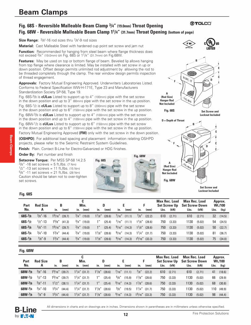
Size Range: 3/8"-16 rod sizes thru 7/8"-9 rod sizes
Material: Cast Malleable Steel with hardened cup point set screw and jam nut
Function: Recommended for hanging from steel beam where flange thickness doesnot exceed 3/4” (19.0mm) on Fig. 68S or 11/4” (31.7mm) on Fig.68W.
Features: May be used on top or bottom flange of beam. Beveled lip allows hangingfrom top flange where clearance is limited. May be installed with set screw in up ordown position. Offset design permits unlimited rod adjustment by allowing the rod tobe threaded completely through the clamp. The rear window design permits inspectionof thread engagement.
Approvals: Factory Mutual Engineering Approved. Underwriters Laboratories Listed.Conforms to Federal Specification WW-H-171E, Type 23 and ManufacturersStandardization Society SP-58, Type 19. Fig. 68S-3/8 is cULus Listed to support up to 4” (100mm) pipe with the set screw in the down position and up to 3” (80mm) pipe with the set screw in the up position.Fig. 68S-1/2 is cULus Listed to support up to 8” (200mm) pipe with the set screw in the down position and up to 6” (150mm) pipe with the set screw in the up position.Fig. 68W-3/8 is cULus Listed to support up to 4” (100mm) pipe with the set screw in the down position and up to 4” (100mm) pipe with the set screw in the up position.Fig. 68W-1/2 is cULus Listed to support up to 6” (150mm) pipe with the set screw in the down position and up to 6” (150mm) pipe with the set screw in the up position.Factory Mutual Engineering Approved (FM) only with the set screw in the down position.
(OSHPD). For additional load spacing and placement information relating OSHPDprojects, please refer to the Seismic Restraint System Guidelines.
Finish: Plain. Contact B-Line for Electro-Galvanized or HDG finishes.
Order By: Part number and finish
Setscrew Torque: Per MSS SP-58 14.2.53/8” -16 set screws = 5 ft./lbs. (7 Nm)1/2” -13 set screws = 11 ft./lbs. (15 Nm)5/8” -11 set screws = 21 ft./lbs. (28 Nm)Caution should be taken not to over-tightenset screws.
C Max Rec. Load Max Rec. Load Approx.Part Rod Size B Min. D E F Set Screw Up Set Screw Down Wt./100No. A in. (mm) in. (mm) in. (mm) in. (mm) in. (mm) Lbs. (kN) Lbs. (kN) Lbs. (kg)
68W-3/8 3/8”-16 19/16” (39.7) 11/4” (31.7) 11/8” (28.6) 7/16” (11.1) 7/8” (22.2) 610 (2.71) 610 (2.71) 41 (18.6)
68W-1/2 1/2”-13 19/16” (39.7) 11/4” (31.7) 1” (25.4) 5/8” (15.9) 11/8” (28.6) 750 (3.33) 1130 (5.02) 66 (29.9)
68W-5/8 5/8”-11 11/2” (38.1) 11/4” (31.7) 1” (25.4) 9/16” (14.3) 11/8” (28.6) 750 (3.33) 1130 (5.02) 68 (30.8)
68W-3/4 3/4”-10 13/4” (44.4) 11/4” (31.7) 11/8” (28.6) 3/8” (19.5) 11/4” (31.7) 750 (3.33) 1130 (5.02) 110 (49.9)
68W-7/8 7/8”-9 13/4” (44.4) 11/4” (31.7) 11/8” (28.6) 9/16” (14.3) 15/16” (33.3) 750 (3.33) 1130 (5.02) 98 (44.4)
Fig. 68S - Reversible Malleable Beam Clamp 3/4” (19.0mm) Throat OpeningFig. 68W - Reversible Malleable Beam Clamp 11/4” (31.7mm) Throat Opening (bottom of page)
Fig. 68SFig. 68W
Fig. 68W
C Max Rec. Load Max Rec. Load Approx.Part Rod Size B Min. D E F Set Screw Up Set Screw Down Wt./100No. A in. (mm) in. (mm) in. (mm) in. (mm) in. (mm) Lbs. (kN) Lbs. (kN) Lbs. (kg)
68S-3/8 3/8”-16 19/16” (39.7) 3/4” (19.0) 11/8” (28.6) 7/16” (11.1) 7/8” (22.2) 610 (2.71) 610 (2.71) 32 (14.5)
68S-1/2 1/2”-13 15/8” (41.3) 3/4” (19.0) 1” (25.4) 7/16” (11.1) 11/8” (28.6) 750 (3.33) 1130 (5.02) 54 (24.5)
68S-5/8 5/8”-11 19/16” (39.7) 3/4” (19.0) 1” (25.4) 9/16” (14.3) 11/8” (28.6) 750 (3.33) 1130 (5.02) 50 (22.7)
68S-3/4 3/4”-10 13/4” (44.4) 3/4” (19.0) 11/8” (28.6) 9/16” (14.3) 11/4” (31.7) 750 (3.33) 1130 (5.02) 81 (36.7)
68S-7/8 7/8”-9 13/4” (44.4) 3/4” (19.0) 11/8” (28.6) 9/16” (14.3) 15/16” (33.3) 750 (3.33) 1130 (5.02) 75 (34.0)
Fig. 68S
Set Screw andLocknut Included
A(Rod Size)Hanger RodNot Included
B
DF
E
C
Set Screw andLocknut Included
A(Rod Size)Hanger RodNot Included
B
DF
E
C
Fig. 68S
Fig. 68W
D = Depth of Throat
Beam Clamps
All dimensions in charts and on drawings are in inches. Dimensions shown in parentheses are in millimeters unless otherwise specified.
Beam Clamps
13Fire Protection Solutions
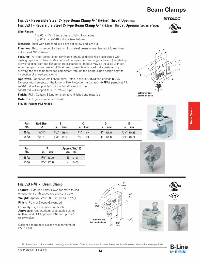
Size Range:Fig. 65 - 1/2"-13 rod sizes, and 5/8"-11 rod sizesFig. 65XT - 3/8"-16 rod size (see below)
Material: Steel with hardened cup point set screw and jam nut
Function: Recommended for hanging from steel beam where flange thickness doesnot exceed 3/4” (19.0mm).
Features: All steel construction eliminates structural deficiencies associated withcasting type beam clamps. May be used on top or bottom flange of beam. (Beveled lipallows hanging from top flange where clearance is limited.) May be installed with setscrew in up or down position. Offset design permits unlimited rod adjustment byallowing the rod to be threaded completely through the clamp. Open design permitsinspection of thread engagement.
Approvals: Underwriters Laboratories Listed in the USA (UL) and Canada (cUL).Exceeds requirements of the National Fire Protection Association (NFPA), pamphlet 13,3/8"-16 rod will support 1/2” (15mm) thru 4” (100mm) pipe1/2"-13 rod will support thru 8” (200mm) pipe
Finish: Plain. Contact B-Line for alternative finishes and materials.
Order By: Figure number and finish
Fig. 65 Patent #4,570,885
Part Rod Size B C D ENo. A in. (mm) in. (mm) in. (mm) in. (mm)
65-1/2 1/2”-13 11/2” (38.1) 3/4” (19.0) 1” (25.4) 9/16” (14.3)
65-5/8 5/8”-11 11/2” (38.1) 3/4” (19.0) 1” (25.4) 9/16” (14.3)
Part F Approx. Wt./100No. in. (mm) Lbs. (kg)
65-1/2 11/4” (31.7) 55 (24.9)
65-5/8 11/4” (31.7) 55 (24.9)
Fig. 65 - Reversible Steel C-Type Beam Clamp 3/4” (19.0mm) Throat OpeningFig. 65XT - Reversible Steel C-Type Beam Clamp 3/4” (19.0mm) Throat Opening (bottom of page)
Fig. 65XT-3/8 - Beam Clamp
B
F
E
A
C
D
Feature: Extruded holes allows for more threadengagement of threaded rod and set screw.
Weight: Approx. Wt./100 - 28.0 Lbs. (12.7kg)
Finish: Plain or Electro-Galvanized
Order By: Figure number and finishApprovals: Underwriters Laboratories Listed(cULus) and FM Approved (FM) for up to 4”(100mm) pipe.
Designed to meet or exceed requirements ofFM DS 2-0.
3/4"(19.0)
19/16"(39.7)
1"(25.4)
7/8"(22.2)
13/8"(34.9)
Set Screw andLocknut Included
Set Screw andLocknut Included
Beam
Clam
ps
All dimensions in charts and on drawings are in inches. Dimensions shown in parentheses are in millimeters unless otherwise specified.
Beam Clamps
Fire Protection Solutions14
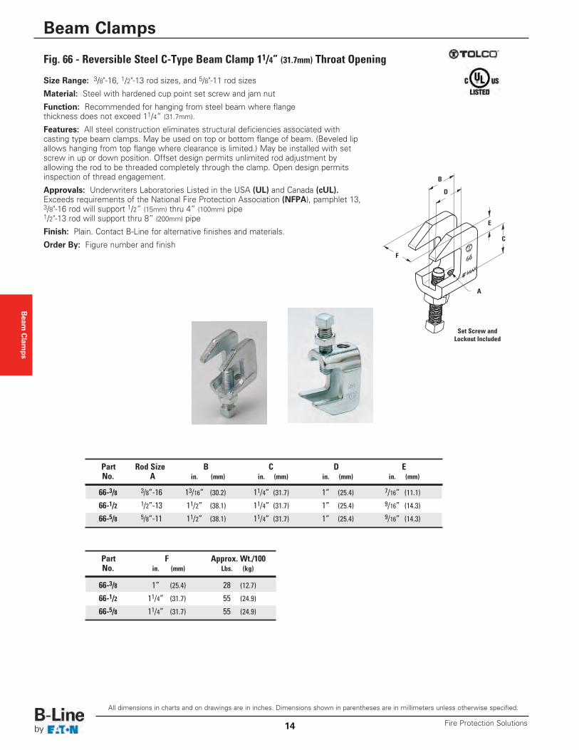
Size Range: 3/8"-16, 1/2"-13 rod sizes, and 5/8"-11 rod sizes
Material: Steel with hardened cup point set screw and jam nut
Function: Recommended for hanging from steel beam where flangethickness does not exceed 11/4” (31.7mm).
Features: All steel construction eliminates structural deficiencies associated with casting type beam clamps. May be used on top or bottom flange of beam. (Beveled lipallows hanging from top flange where clearance is limited.) May be installed with setscrew in up or down position. Offset design permits unlimited rod adjustment byallowing the rod to be threaded completely through the clamp. Open design permitsinspection of thread engagement.
Approvals: Underwriters Laboratories Listed in the USA (UL) and Canada (cUL).Exceeds requirements of the National Fire Protection Association (NFPA), pamphlet 13,3/8"-16 rod will support 1/2” (15mm) thru 4” (100mm) pipe1/2"-13 rod will support thru 8” (200mm) pipe
Finish: Plain. Contact B-Line for alternative finishes and materials.
Order By: Figure number and finish
Fig. 66 - Reversible Steel C-Type Beam Clamp 11/4” (31.7mm) Throat Opening
B
E
A
C
D
F
Set Screw andLocknut Included
Part Rod Size B C D ENo. A in. (mm) in. (mm) in. (mm) in. (mm)
66-3/8 3/8”-16 13/16” (30.2) 11/4” (31.7) 1” (25.4) 7/16” (11.1)
66-1/2 1/2”-13 11/2” (38.1) 11/4” (31.7) 1” (25.4) 9/16” (14.3)
66-5/8 5/8”-11 11/2” (38.1) 11/4” (31.7) 1” (25.4) 9/16” (14.3)
Part F Approx. Wt./100No. in. (mm) Lbs. (kg)
66-3/8 1” (25.4) 28 (12.7)
66-1/2 11/4” (31.7) 55 (24.9)
66-5/8 11/4” (31.7) 55 (24.9)
Beam Clamps
All dimensions in charts and on drawings are in inches. Dimensions shown in parentheses are in millimeters unless otherwise specified.
Beam Clamps
15Fire Protection Solutions
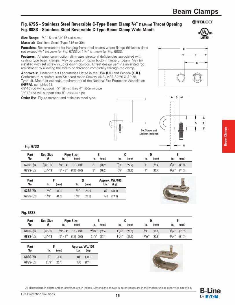
Size Range: 3/8"-16 and 1/2"-13 rod sizesMaterial: Stainless Steel (Type 316 or 304)Function: Recommended for hanging from steel beams where flange thickness doesnot exceed 3/4” (19.0mm) for Fig. 67SS or 11/4” (31.7mm) for Fig. 68SS.Features: All steel construction eliminates structural deficiencies associated withcasting type beam clamps. May be used on top or bottom flange of beam. May beinstalled with set screw in up or down position. Offset design permits unlimited rodadjustment by allowing the rod to be threaded completely through the clamp.Approvals: Underwriters Laboratories Listed in the USA (UL) and Canada (cUL).Conforms to Manufacturers Standardization Society ANSI/MSS SP-69 & SP-58,Type 19. Meets or exceeds requirements of the National Fire Protection Association(NFPA), pamphlet 13.3/8"-16 rod will support 1/2” (15mm) thru 4” (100mm) pipe1/2"-13 rod will support thru 8” (200mm) pipeOrder By: Figure number and stainless steel type.
Part Rod Size Pipe Size B C D ENo. A in. (mm) in. (mm) in. (mm) in. (mm) in. (mm)
67SS-3/8 3/8”-16 1/2" - 4” (15 - 100) 3” (76,2) 7/8” (22.2) 1” (25.4) 15/8” (41.3)
67SS-1/2 1/2”-13 5" - 8” (125 -200) 3” (76,2) 7/8” (22.2) 1” (25.4) 15/8” (41.3)
Part F G Approx. Wt./100No. in. (mm) in. (mm) Lbs. (kg)
67SS-3/8 15/8” (41.3) 11/8” (28.6) 84 (38.1)
67SS-1/2 15/8” (41.3) 11/8” (28.6) 170 (77.1)
Part Rod Size Pipe Size B C D ENo. A in. (mm) in. (mm) in. (mm) in. (mm) in. (mm)
68SS-3/8 3/8”-16 1/2" - 4” (15 - 100) 21/16” (52.4) 11/8” (28.6) 3/4” (19.0) 11/4” (31.7)
68SS-1/2 1/2”-13 5" - 8” (125 -200) 21/4” (57.1) 11/4” (31.7) 13/16” (20.6) 11/4” (31.7)
Part F Approx. Wt./100No. in. (mm) Lbs. (kg)
68SS-3/8 2” (50.8) 84 (38.1)
68SS-1/2 21/4” (57.1) 170 (77.1)
Fig. 67SS - Stainless Steel Reversible C-Type Beam Clamp 3/4” (19.0mm) Throat OpeningFig. 68SS - Stainless Steel Reversible C-Type Beam Clamp Wide Mouth
Fig. 67SS
Fig. 68SS
B
G
E
A
C
D
F
Set Screw andLocknut Included
Beam
Clam
ps
All dimensions in charts and on drawings are in inches. Dimensions shown in parentheses are in millimeters unless otherwise specified.
Beam Clamps
Fire Protection Solutions16
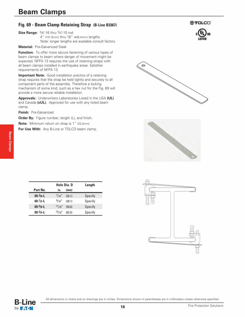
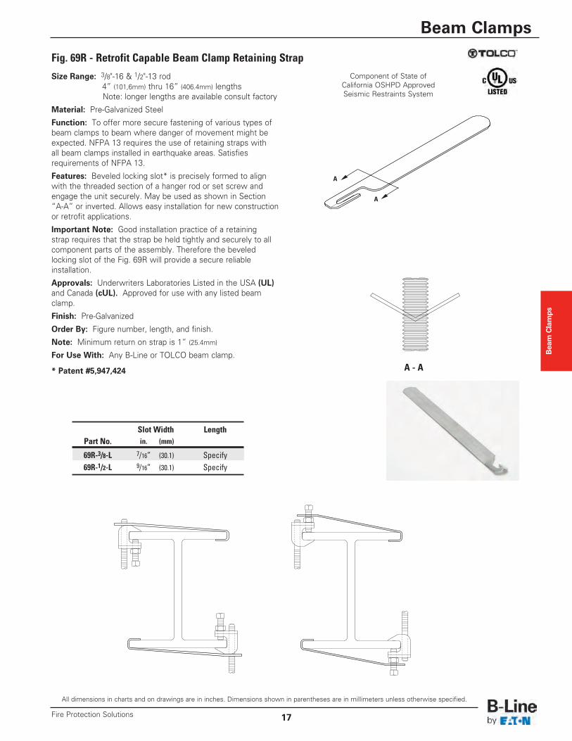
Size Range: 3/8"-16 thru 3/4"-10 rod 4” (101.6mm) thru 16” (406.4mm) lengthsNote: longer lengths are available consult factory
Material: Pre-Galvanized Steel
Function: To offer more secure fastening of various types ofbeam clamps to beam where danger of movement might beexpected. NFPA 13 requires the use of retaining straps withall beam clamps installed in earthquake areas. Satisfiesrequirements of NFPA 13.
Important Note: Good installation practice of a retainingstrap requires that the strap be held tightly and securely to allcomponent parts of the assembly. Therefore a lockingmechanism of some kind, such as a hex nut for the Fig. 69 willprovide a more secure reliable installation.
Approvals: Underwriters Laboratories Listed in the USA (UL)and Canada (cUL). Approved for use with any listed beamclamp.
Finish: Pre-Galvanized
Order By: Figure number, length (L), and finish.
Note: Minimum return on strap is 1” (25.4mm)
For Use With: Any B-Line or TOLCO beam clamp.
Fig. 69 - Beam Clamp Retaining Strap (B-Line B3367)
Hole Dia. D LengthPart No. in. (mm)
69-3/8-L 7/16” (30.1) Specify69-1/2-L 9/16” (30.1) Specify
69-5/8-L 11/16” (50.8) Specify
69-3/4-L 13/16” (63.5) Specify
Beam Clamps
All dimensions in charts and on drawings are in inches. Dimensions shown in parentheses are in millimeters unless otherwise specified.
Beam Clamps
17Fire Protection Solutions
Size Range: 3/8"-16 & 1/2"-13 rod 4” (101,6mm) thru 16” (406.4mm) lengthsNote: longer lengths are available consult factory
Material: Pre-Galvanized Steel
Function: To offer more secure fastening of various types ofbeam clamps to beam where danger of movement might beexpected. NFPA 13 requires the use of retaining straps withall beam clamps installed in earthquake areas. Satisfiesrequirements of NFPA 13.
Features: Beveled locking slot* is precisely formed to alignwith the threaded section of a hanger rod or set screw andengage the unit securely. May be used as shown in Section“A-A” or inverted. Allows easy installation for new constructionor retrofit applications.
Important Note: Good installation practice of a retainingstrap requires that the strap be held tightly and securely to allcomponent parts of the assembly. Therefore the beveledlocking slot of the Fig. 69R will provide a secure reliableinstallation.
Approvals: Underwriters Laboratories Listed in the USA (UL)and Canada (cUL). Approved for use with any listed beamclamp.
Finish: Pre-Galvanized
Order By: Figure number, length, and finish.
Note: Minimum return on strap is 1” (25.4mm)
For Use With: Any B-Line or TOLCO beam clamp.
* Patent #5,947,424
Fig. 69R - Retrofit Capable Beam Clamp Retaining StrapComponent of State of
California OSHPD ApprovedSeismic Restraints System
A
A
A - A
Slot Width LengthPart No. in. (mm)
69R-3/8-L 7/16” (30.1) Specify69R-1/2-L 9/16” (30.1) Specify
Beam
Clam
ps
All dimensions in charts and on drawings are in inches. Dimensions shown in parentheses are in millimeters unless otherwise specified.
Beam Clamps
Fire Protection Solutions18
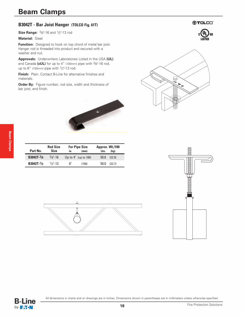
Size Range: 3/8"-16 and 1/2"-13 rod
Material: Steel
Function: Designed to hook on top chord of metal bar joist.Hanger rod is threaded into product and secured with awasher and nut.
Approvals: Underwriters Laboratories Listed in the USA (UL)and Canada (cUL) for up to 4” (100mm) pipe with 3/8"-16 rod,up to 6” (150mm) pipe with 1/2"-13 rod.
Finish: Plain. Contact B-Line for alternative finishes andmaterials.
Order By: Figure number, rod size, width and thickness ofbar joist, and finish.
B3042T - Bar Joist Hanger (TOLCO Fig. 61T)
Rod Size For Pipe Size Approx. Wt./100Part No. Size in. (mm) Lbs. (kg)
B3042T-3/8 3/8"-16 Up to 4" (up to 100) 50.6 (22.9)
B3042T-1/2 1/2"-13 6" (150) 50.0 (22.7)
Beam Clamps
All dimensions in charts and on drawings are in inches. Dimensions shown in parentheses are in millimeters unless otherwise specified.
Beam Clamps
19Fire Protection Solutions
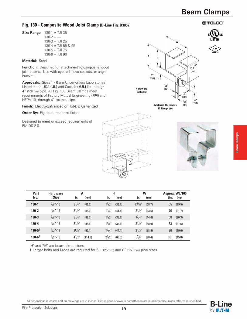
Size Range: 130-1 = TJI 35130-2 = ––130-3 = TJI 25130-4 = TJI 55 & 65130-5 = TJI 75130-6 = TJI 96
Material: Steel
Function: Designed for attachment to composite woodjoist beams. Use with eye rods, eye sockets, or anglebracket.
Approvals: Sizes 1 - 6 are Underwriters LaboratoriesListed in the USA (UL) and Canada (cUL) list through4” (100mm) pipe. All Fig. 130 Beam Clamps meetrequirements of Factory Mutual Engineering (FM) andNFPA 13, through 4” (100mm) pipe.
Finish: Electro-Galvanized or Hot-Dip Galvanized
Order By: Figure number and finish.
Designed to meet or exceed requirements ofFM DS 2-0.
Fig. 130 - Composite Wood Joist Clamp (B-Line Fig. B3052)
HardwareIncluded
3/4"(19.0)
3/8"(9.5)
1/8"(3.2)
2"(50.8)
1"(25.4)
W
HA
Material Thickness11 Gauge (3.0)
Part Hardware A H W Approx. Wt./100No. Size in. (mm) in. (mm) in. (mm) Lbs. (kg)
130-1 3/8”-16 31/4" (82.5) 11/2" (38.1) 25/16" (58.7) 65 (29.5)
130-2 3/8”-16 31/2" (88.9) 13/4" (44.4) 21/2" (63.5) 70 (31.7)
130-3 3/8”-16 31/4" (82.5) 11/2" (38.1) 13/4" (44.4) 58 (26.3)
130-4 3/8”-16 31/2" (88.9) 11/2" (38.1) 31/2" (88.9) 83 (37.6)
130-5† 1/2”-13 35/8" (92.1) 13/4" (44.4) 31/2" (88.9) 86 (39.0)
130-6† 1/2”-13 41/2" (114.3) 21/2" (63.5) 37/8" (98.4) 101 (45.8)
‘H’ and ‘W’ are beam dimensions.† Larger bolts and I-rods are required for 5” (125mm) and 6” (150mm) pipe sizes
All dimensions in charts and on drawings are in inches. Dimensions shown in parentheses are in millimeters unless otherwise specified.
Pipe Hangers
Fire Protection Solutions20
Pipe Hangers
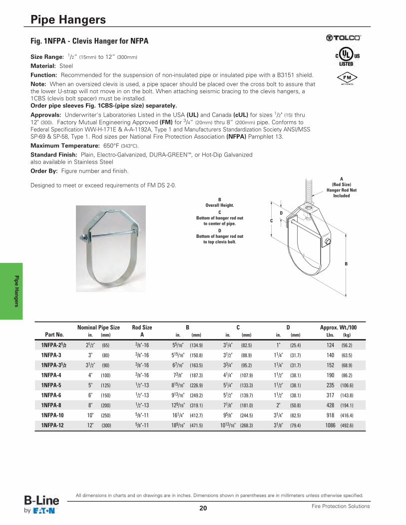
Fig. 1NFPA - Clevis Hanger for NFPA
BOverall Height.
CBottom of hanger rod nut
to center of pipe.
DBottom of hanger rod nut
to top clevis bolt.
Size Range: 1/2” (15mm) to 12” (300mm)
Material: Steel
Function: Recommended for the suspension of non-insulated pipe or insulated pipe with a B3151 shield.
Note: When an oversized clevis is used, a pipe spacer should be placed over the cross bolt to assure thatthe lower U-strap will not move in on the bolt. When attaching seismic bracing to the clevis hangers, a1CBS (clevis bolt spacer) must be installed.Order pipe sleeves Fig. 1CBS-(pipe size) separately.
Approvals: Underwriter's Laboratories Listed in the USA (UL) and Canada (cUL) for sizes 1/2" (15) thru12" (300). Factory Mutual Engineering Approved (FM) for 3/4” (20mm) thru 8” (200mm) pipe. Conforms toFederal Specification WW-H-171E & A-A-1192A, Type 1 and Manufacturers Standardization Society ANSI/MSSSP-69 & SP-58, Type 1. Rod sizes per National Fire Protection Association (NFPA) Pamphlet 13.
Maximum Temperature: 650°F (343°C).
Standard Finish: Plain, Electro-Galvanized, DURA-GREEN™, or Hot-Dip Galvanizedalso available in Stainless Steel
Order By: Figure number and finish.
Designed to meet or exceed requirements of FM DS 2-0.
Nominal Pipe Size Rod Size B C D Approx. Wt./100Part No. in. (mm) A in. (mm) in. (mm) in. (mm) Lbs. (kg)
1NFPA-21/2 21/2" (65) 3/8"-16 55/16" (134.9) 31/4" (82.5) 1" (25.4) 124 (56.2)
1NFPA-3 3" (80) 3/8"-16 515/16" (150.8) 31/2" (88.9) 11/4" (31.7) 140 (63.5)
1NFPA-31/2 31/2" (90) 3/8"-16 67/16" (163.5) 33/4" (95.2) 11/4" (31.7) 152 (68.9)
1NFPA-4 4" (100) 3/8"-16 73/8" (187.3) 41/4" (107.9) 11/2" (38.1) 190 (86.2)
1NFPA-5 5" (125) 1/2"-13 815/16" (226.9) 51/4" (133.3) 11/2" (38.1) 235 (106.6)
1NFPA-6 6" (150) 1/2"-13 913/16" (249.2) 51/2" (139.7) 11/2" (38.1) 317 (143.8)
1NFPA-8 8" (200) 1/2"-13 129/16" (319.1) 71/8" (181.0) 2" (50.8) 428 (194.1)
1NFPA-10 10" (250) 5/8"-11 161/4" (412.7) 95/8" (244.5) 31/4" (82.5) 918 (416.4)
1NFPA-12 12" (300) 5/8"-11 189/16" (471.5) 1013/16" (268.3) 31/8" (79.4) 1086 (492.6)
B
D
C
A(Rod Size)
Hanger Rod NotIncluded
All dimensions in charts and on drawings are in inches. Dimensions shown in parentheses are in millimeters unless otherwise specified.
Pipe Hangers
21Fire Protection Solutions
Pipe Hangers
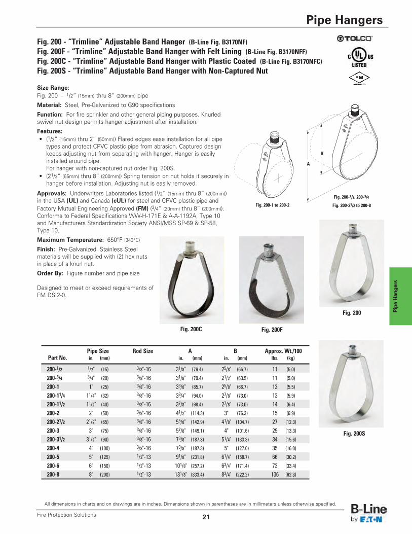
Fig. 200 - “Trimline” Adjustable Band Hanger (B-Line Fig. B3170NF)Fig. 200F - “Trimline” Adjustable Band Hanger with Felt Lining (B-Line Fig. B3170NFF)Fig. 200C - “Trimline” Adjustable Band Hanger with Plastic Coated (B-Line Fig. B3170NFC)Fig. 200S - “Trimline” Adjustable Band Hanger with Non-Captured Nut
Size Range:Fig. 200 - 1/2” (15mm) thru 8” (200mm) pipe
Material: Steel, Pre-Galvanized to G90 specifications
Function: For fire sprinkler and other general piping purposes. Knurledswivel nut design permits hanger adjustment after installation.
Features:• (1/2” (15mm) thru 2” (50mm)) Flared edges ease installation for all pipe
types and protect CPVC plastic pipe from abrasion. Captured design keeps adjusting nut from separating with hanger. Hanger is easilyinstalled around pipe.For hanger with non-captured nut order Fig. 200S.
• (21/2” (65mm) thru 8” (200mm)) Spring tension on nut holds it securely inhanger before installation. Adjusting nut is easily removed.
Approvals: Underwriters Laboratories listed (1/2” (15mm) thru 8” (200mm))in the USA (UL) and Canada (cUL) for steel and CPVC plastic pipe andFactory Mutual Engineering Approved (FM) (3/4” (20mm) thru 8” (200mm)).Conforms to Federal Specifications WW-H-171E & A-A-1192A, Type 10and Manufacturers Standardization Society ANSI/MSS SP-69 & SP-58,Type 10.
Maximum Temperature: 650°F (343°C)
Finish: Pre-Galvanized. Stainless Steelmaterials will be supplied with (2) hex nutsin place of a knurl nut.
Order By: Figure number and pipe size
Designed to meet or exceed requirements ofFM DS 2-0.
A
B
Fig. 200-1 to 200-2 Fig. 200-21/2 to 200-8
Pipe Size Rod Size A B Approx. Wt./100Part No. in. (mm) in. (mm) in. (mm) lbs. (kg)
200-1/2 1/2" (15) 3/8"-16 31/8" (79.4) 25/8" (66.7) 11 (5.0)
200-3/4 3/4" (20) 3/8"-16 31/8" (79.4) 21/2" (63.5) 11 (5.0)
200-1 1" (25) 3/8"-16 33/8" (85.7) 25/8" (66.7) 12 (5.5)
200-11/4 11/4" (32) 3/8"-16 33/4" (94.0) 27/8" (73.0) 13 (5.9)
200-11/2 11/2" (40) 3/8"-16 37/8" (98.4) 27/8" (73.0) 14 (6.4)
200-2 2" (50) 3/8"-16 41/2" (114.3) 3" (76.3) 15 (6.9)
200-21/2 21/2" (65) 3/8"-16 55/8" (142.9) 41/8" (104.7) 27 (12.3)
200-3 3" (75) 3/8"-16 57/8" (149.1) 4" (101.6) 29 (13.3)
200-31/2 31/2" (90) 3/8"-16 73/8" (187.3) 51/4" (133.3) 34 (15.6)
200-4 4" (100) 3/8"-16 73/8" (187.3) 5" (127.0) 35 (16.0)
200-5 5" (125) 1/2"-13 91/8" (231.8) 61/4" (158.7) 66 (30.2)
200-6 6" (150) 1/2"-13 101/8" (257.2) 63/4" (171.4) 73 (33.4)
200-8 8" (200) 1/2"-13 131/8" (333.4) 83/4" (222.2) 136 (62.3)
Fig. 200-1/2. 200-3/4
Fig. 200C Fig. 200F
Fig. 200
Fig. 200S
Pipe Hangers
All dimensions in charts and on drawings are in inches. Dimensions shown in parentheses are in millimeters unless otherwise specified.
Pipe Hangers
Fire Protection Solutions22
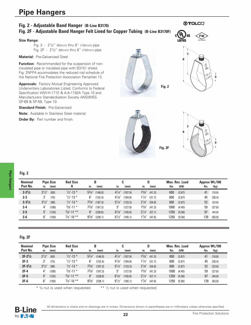
Fig. 2 - Adjustable Band Hanger (B-Line B3170)Fig. 2F - Adjustable Band Hanger Felt Lined for Copper Tubing (B-Line B3170F)
Size Range:Fig. 2 - 21/2” (65mm) thru 6” (150mm) pipeFig. 2F - 21/2” (65mm) thru 6” (150mm) pipe
Material: Pre-Galvanized Steel
Function: Recommended for the suspension of non-insulated pipe or insulated pipe with B3151 shield.Fig. 2NFPA accomodates the reduced rod schedule ofthe National Fire Pretection Association Pamphlet 13.
Approvals: Factory Mutual Engineering Approved.Underwriters Laboratories Listed. Conforms to FederalSpecification WW-H-171E & A-A-1192A Type 10 andManufacturers Standardization Society ANSI/MSSSP-69 & SP-58, Type 10.
Standard Finish: Pre-Galvanized
Note: Available in Stainless Steel material.
Order By: Part number and finish.
Nominal Pipe Size Rod Size B C D Max. Rec. Load Approx Wt./100Part No. in. (mm) A in. (mm) in. (mm) in. (mm) lbs. (kN) lbs. (kg)
2-21/2 21/2" (65) 1/2"-13 * 53/4" (146.0) 41/4" (107.9) 15/8" (41.3) 600 (2.67) 41 (18.6)2-3 3" (75) 1/2"-13 * 6" (152.4) 41/8" (104.8) 11/4" (31.7) 600 (2.67) 45 (20.4)2-31/2 31/2" (90) 1/2"-13 * 73/8" (187.3) 51/4" (133.3) 21/8" (54.0) 600 (2.67) 52 (23.6)2-4 4" (100) 5/8"-11 * 73/8" (187.3) 5" (127.0) 15/8" (41.3) 1000 (4.45) 59 (27.6)2-5 5" (125) 5/8"-11 ** 9" (228.6) 61/8" (155.6) 21/4" (57.1) 1250 (5.56) 97 (44.0)2-6 6" (150) 3/4"-10 ** 93/8" (238.1) 61/2" (165.1) 17/8" (47.6) 1250 (5.56) 139 (63.0)
Fig. 2
Fig. 2F
Fig. 2
Nominal Pipe Size Rod Size B C D Max. Rec. Load Approx Wt./100Part No. in. (mm) A in. (mm) in. (mm) in. (mm) lbs. (kN) lbs. (kg)
2F-21/2 21/2" (65) 1/2"-13 * 53/4" (146.0) 41/4" (107.9) 15/8" (41.3) 600 (2.67) 41 (18.6)2F-3 3" (75) 1/2"-13 * 6" (152.4) 41/8" (104.8) 11/4" (31.7) 600 (2.67) 45 (20.4)2F-31/2 31/2" (90) 1/2"-13 * 73/8" (187.3) 51/4" (133.3) 21/8" (54.0) 600 (2.67) 52 (23.6)2F-4 4" (100) 5/8"-11 * 73/8" (187.3) 5" (127.0) 15/8" (41.3) 1000 (4.45) 59 (27.6)2F-5 5" (125) 5/8"-11 ** 9" (228.6) 61/8" (155.6) 21/4" (57.1) 1250 (5.56) 97 (44.0)2F-6 6" (150) 3/4"-10 ** 93/8" (238.1) 61/2" (165.1) 17/8" (47.6) 1250 (5.56) 139 (63.0)
Fig. 2F
* 3/8 nut is used when requested. ** 1/2 nut is used when requested.
B
D
C
B
D
C
Pipe Hangers
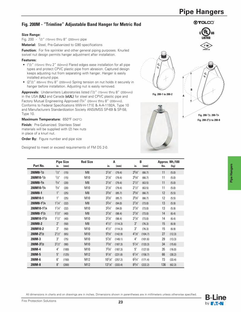
Fig. 200M - “Trimline” Adjustable Band Hanger for Metric Rod
Size Range:Fig. 200 - 1/2” (15mm) thru 8” (200mm) pipe
Material: Steel, Pre-Galvanized to G90 specifications
Function: For fire sprinkler and other general piping purposes. Knurledswivel nut design permits hanger adjustment after installation.
Features:• (1/2” (15mm) thru 2” (50mm)) Flared edges ease installation for all pipe
types and protect CPVC plastic pipe from abrasion. Captured design keeps adjusting nut from separating with hanger. Hanger is easilyinstalled around pipe.
• (21/2” (65mm) thru 8” (200mm)) Spring tension on nut holds it securely inhanger before installation. Adjusting nut is easily removed.
Approvals: Underwriters Laboratories listed (1/2” (15mm) thru 8” (200mm))in the USA (UL) and Canada (cUL) for steel and CPVC plastic pipe andFactory Mutual Engineering Approved (3/4” (20mm) thru 8” (200mm)).Conforms to Federal Specifications WW-H-171E & A-A-1192A, Type 10and Manufacturers Standardization Society ANSI/MSS SP-69 & SP-58,Type 10.
Maximum Temperature: 650°F (343°C)
Finish: Pre-Galvanized. Stainless Steelmaterials will be supplied with (2) hex nutsin place of a knurl nut.
Order By: Figure number and pipe size
Designed to meet or exceed requirements of FM DS 2-0.
A
B
Fig. 200-1 to 200-2
Fig. 200-21/2 to 200-8
Pipe Size Rod Size A B Approx. Wt./100Part No. in. (mm) in. (mm) in. (mm) lbs. (kg)
200M8-1/2 1/2" (15) M8 31/8" (79.4) 25/8" (66.7) 11 (5.0)
200M10-1/2 1/2" (15) M10 31/8" (79.4) 25/8" (66.7) 11 (5.0)
200M8-3/4 3/4" (20) M8 31/8" (79.4) 21/2" (63.5) 11 (5.0)
200M10-3/4 3/4" (20) M10 31/8" (79.4) 21/2" (63.5) 11 (5.0)
200M8-1 1" (25) M8 33/8" (85.7) 25/8" (66.7) 12 (5.5)
200M10-1 1" (25) M10 33/8" (85.7) 25/8" (66.7) 12 (5.5)
200M8-11/4 11/4" (32) M8 33/4" (94.0) 27/8" (73.0) 13 (5.9)
200M10-11/4 11/4" (32) M10 33/4" (94.0) 27/8" (73.0) 13 (5.9)
200M8-11/2 11/2" (40) M8 37/8" (98.4) 27/8" (73.0) 14 (6.4)
200M10-11/2 11/2" (40) M10 37/8" (98.4) 27/8" (73.0) 14 (6.4)
200M8-2 2" (50) M8 41/2" (114.3) 3" (76.3) 15 (6.9)
200M10-2 2" (50) M10 41/2" (114.3) 3" (76.3) 15 (6.9)
200M-21/2 21/2" (65) M10 55/8" (142.9) 41/8" (104.7) 27 (12.3)
200M-3 3" (75) M10 57/8" (149.1) 4" (101.6) 29 (13.3)
200M-31/2 31/2" (90) M10 73/8" (187.3) 51/4" (133.3) 34 (15.6)
200M-4 4" (100) M10 73/8" (187.3) 5" (127.0) 35 (16.0)
200M-5 5" (125) M12 91/8" (231.8) 61/4" (158.7) 66 (30.2)
200M-6 6" (150) M12 101/8" (257.2) 63/4" (171.4) 73 (33.4)
200M-8 8" (200) M12 131/8" (333.4) 83/4" (222.2) 136 (62.3)
Fig. 200-1/2. 200-3/4
All dimensions in charts and on drawings are in inches. Dimensions shown in parentheses are in millimeters unless otherwise specified.
Pipe Hangers
23Fire Protection Solutions
Pipe Hangers
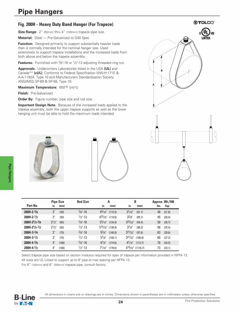
Fig. 200H - Heavy Duty Band Hanger (For Trapeze)Size Range: 2” (50mm) thru 4” (100mm) trapeze pipe size.
Material: Steel — Pre-Galvanized to G40 Spec
Function: Designed primarily to support substantially heavier loadsthan is normally intended for the nominal hanger size. Usedextensively to support trapeze installations and the increased loads fromboth above and below the trapeze assembly.
Features: Furnished with 3/8"-16 or 1/2"-13 adjusting threaded ring nut.
Approvals: Underwriters Laboratories listed in the USA (UL) andCanada** (cUL). Conforms to Federal Specification WW-H-171E &A-A-1192A, Type 10 and Manufacturers Standardization SocietyANSI/MSS SP-69 & SP-58, Type 10.
Maximum Temperature: 650°F (343°C)
Finish: Pre-Galvanized
Order By: Figure number, pipe size and rod size.
Important Design Note. Because of the increased loads applied to thetrapeze assembly, both the upper trapeze supports as well as the lowerhanging unit must be able to hold the maximum loads intended.
A
B
Pipe Size Rod Size A B Approx. Wt./100Part No. in. (mm) in. (mm) in. (mm) lbs. (kg)
200H-2-3/8 2" (50) 3/8"-16 49/16" (115.9) 37/32" (81.7) 48 (21.8)
200H-2-1/2 2" (50) 1/2"-13 423/32" (119.8) 33/8" (85.7) 45 (20.4)
200H-21/2-3/8 21/2" (65) 3/8"-16 55/16" (134.9) 323/32" (94.4) 59 (26.7)
200H-21/2-1/2 21/2" (65) 1/2"-13 515/32" (138.9) 37/8" (98.3) 56 (25.4)
200H-3-3/8 3" (75) 3/8"-16 53/4" (146.0) 327/32" (97.6) 63 (28.6)
200H-3-1/2 3" (75) 1/2"-13 57/8" (148.1) 331/32" (100.8) 60 (27.2)
200H-4-3/8 4" (100) 3/8"-16 67/8" (174.6) 47/16" (112.7) 76 (34.5)
200H-4-1/2 4" (100) 1/2"-13 71/32" (178.6) 419/32" (1116.7) 73 (33.1)
Select trapeze pipe size based on section modulus required for span of trapeze per information provided in NFPA 13.All sizes are UL Listed to support up to 8" pipe at max spacing per NFPA 13.For 6” (150mm) and 8” (200mm) trapeze pipe, consult factory.
All dimensions in charts and on drawings are in inches. Dimensions shown in parentheses are in millimeters unless otherwise specified.
Pipe Hangers
Fire Protection Solutions24
Pipe Hangers
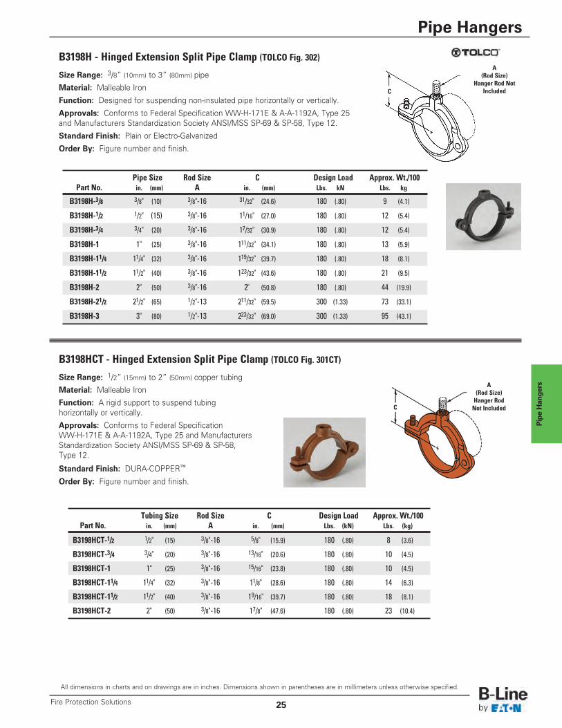
B3198HCT - Hinged Extension Split Pipe Clamp (TOLCO Fig. 301CT)
Tubing Size Rod Size C Design Load Approx. Wt./100Part No. in. (mm) A in. (mm) Lbs. (kN) Lbs. (kg)
B3198HCT-1/2 1/2" (15) 3/8"-16 5/8" (15.9) 180 (.80) 8 (3.6)
B3198HCT-3/4 3/4" (20) 3/8"-16 13/16" (20.6) 180 (.80) 10 (4.5)
B3198HCT-1 1" (25) 3/8"-16 15/16" (23.8) 180 (.80) 10 (4.5)
B3198HCT-11/4 11/4" (32) 3/8"-16 11/8" (28.6) 180 (.80) 14 (6.3)
B3198HCT-11/2 11/2" (40) 3/8"-16 19/16" (39.7) 180 (.80) 18 (8.1)
B3198HCT-2 2" (50) 3/8"-16 17/8" (47.6) 180 (.80) 23 (10.4)
Size Range: 1/2” (15mm) to 2” (50mm) copper tubing
Material: Malleable Iron
Function: A rigid support to suspend tubinghorizontally or vertically.
Approvals: Conforms to Federal SpecificationWW-H-171E & A-A-1192A, Type 25 and ManufacturersStandardization Society ANSI/MSS SP-69 & SP-58,Type 12.
Standard Finish: DURA-COPPER™
Order By: Figure number and finish.
A(Rod Size)Hanger RodNot IncludedC
Size Range: 3/8” (10mm) to 3” (80mm) pipe
Material: Malleable Iron
Function: Designed for suspending non-insulated pipe horizontally or vertically.
Approvals: Conforms to Federal Specification WW-H-171E & A-A-1192A, Type 25and Manufacturers Standardization Society ANSI/MSS SP-69 & SP-58, Type 12.
Standard Finish: Plain or Electro-Galvanized
Order By: Figure number and finish.
B3198H - Hinged Extension Split Pipe Clamp (TOLCO Fig. 302)A
(Rod Size)Hanger Rod Not
IncludedC
Pipe Size Rod Size C Design Load Approx. Wt./100Part No. in. (mm) A in. (mm) Lbs. kN Lbs. kg
B3198H-3/8 3/8" (10) 3/8"-16 31/32" (24.6) 180 (.80) 9 (4.1)
B3198H-1/2 1/2" (15) 3/8"-16 11/16" (27.0) 180 (.80) 12 (5.4)
B3198H-3/4 3/4" (20) 3/8"-16 17/32" (30.9) 180 (.80) 12 (5.4)
B3198H-1 1" (25) 3/8"-16 111/32" (34.1) 180 (.80) 13 (5.9)
B3198H-11/4 11/4" (32) 3/8"-16 119/32" (39.7) 180 (.80) 18 (8.1)
B3198H-11/2 11/2" (40) 3/8"-16 123/32" (43.6) 180 (.80) 21 (9.5)
B3198H-2 2" (50) 3/8"-16 2" (50.8) 180 (.80) 44 (19.9)
B3198H-21/2 21/2" (65) 1/2"-13 211/32" (59.5) 300 (1.33) 73 (33.1)
B3198H-3 3" (80) 1/2"-13 223/32" (69.0) 300 (1.33) 95 (43.1)
All dimensions in charts and on drawings are in inches. Dimensions shown in parentheses are in millimeters unless otherwise specified.
Pipe Hangers
25Fire Protection Solutions
Pipe Hangers
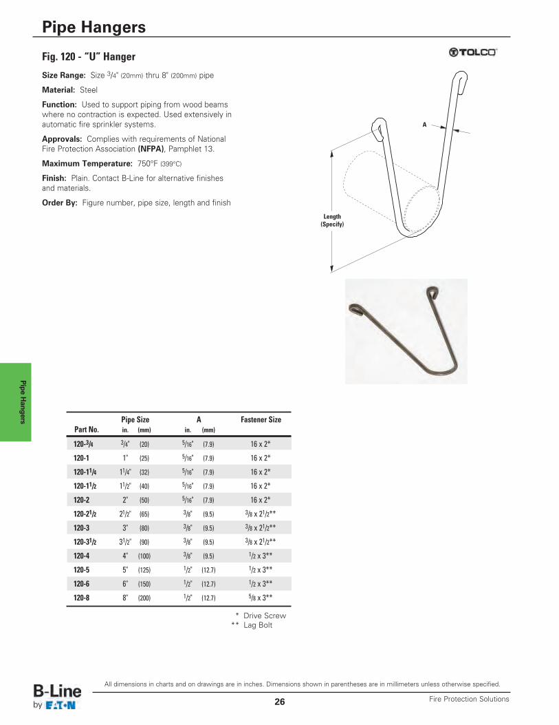
Fig. 120 - “U” Hanger
Size Range: Size 3/4" (20mm) thru 8" (200mm) pipe
Material: Steel
Function: Used to support piping from wood beamswhere no contraction is expected. Used extensively inautomatic fire sprinkler systems.
Approvals: Complies with requirements of NationalFire Protection Association (NFPA), Pamphlet 13.
Maximum Temperature: 750°F (399°C)
Finish: Plain. Contact B-Line for alternative finishesand materials.
Order By: Figure number, pipe size, length and finish
Length(Specify)
A
Pipe Size A Fastener SizePart No. in. (mm) in. (mm)
120-3/4 3/4" (20) 5/16" (7.9) 16 x 2*
120-1 1" (25) 5/16" (7.9) 16 x 2*
120-11/4 11/4" (32) 5/16" (7.9) 16 x 2*
120-11/2 11/2" (40) 5/16" (7.9) 16 x 2*
120-2 2" (50) 5/16" (7.9) 16 x 2*
120-21/2 21/2" (65) 3/8" (9.5) 3/8 x 21/2**
120-3 3" (80) 3/8" (9.5) 3/8 x 21/2**
120-31/2 31/2" (90) 3/8" (9.5) 3/8 x 21/2**
120-4 4" (100) 3/8" (9.5) 1/2 x 3**
120-5 5" (125) 1/2" (12.7) 1/2 x 3**
120-6 6" (150) 1/2" (12.7) 1/2 x 3**
120-8 8" (200) 1/2" (12.7) 5/8 x 3**
* Drive Screw** Lag Bolt
All dimensions in charts and on drawings are in inches. Dimensions shown in parentheses are in millimeters unless otherwise specified.
Pipe Hangers
Fire Protection Solutions26
Pipe Hangers
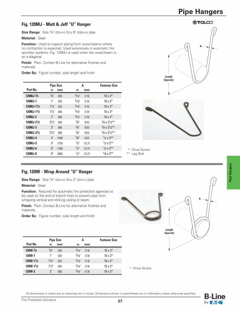
Fig. 120MJ - Mutt & Jeff “U” Hanger
Size Range: Size 3/4" (20mm) thru 8" (200mm) pipe
Material: Steel
Function: Used to support piping from wood beams whereno contraction is expected. Used extensively in automatic firesprinkler systems. Fig. 120MJ is used when the wood beam ison a diagonal.
Finish: Plain. Contact B-Line for alternative finishes andmaterials.
Order By: Figure number, side length and finish
A
Pipe Size A Fastener SizePart No. in. (mm) in. (mm)
120MJ-3/4 3/4" (20) 5/16" (7.9) 16 x 2*120MJ-1 1" (25) 5/16" (7.9) 16 x 2*120MJ-11/4 11/4" (32) 5/16" (7.9) 16 x 2*120MJ-11/2 11/2" (40) 5/16" (7.9) 16 x 2* 120MJ-2 2" (50) 5/16" (7.9) 16 x 2* 120MJ-21/2 21/2" (65) 3/8" (9.5) 3/8 x 21/2**120MJ-3 3" (80) 3/8" (9.5) 3/8 x 21/2**120MJ-31/2 31/2" (90) 3/8" (9.5) 3/8 x 21/2**120MJ-4 4" (100) 3/8" (9.5) 1/2 x 3**120MJ-5 5" (125) 1/2" (12.7) 1/2 x 3**120MJ-6 6" (150) 1/2" (12.7) 1/2 x 3**120MJ-8 8" (200) 1/2" (12.7) 5/8 x 3**
Pipe Size A Fastener SizePart No. in. (mm) in. (mm)
120W-3/4 3/4" (20) 5/16" (7.9) 16 x 2*120W-1 1" (25) 5/16" (7.9) 16 x 2*120W-11/4 11/4" (32) 5/16" (7.9) 16 x 2*120W-11/2 11/2" (40) 5/16" (7.9) 16 x 2* 120W-2 2" (50) 5/16" (7.9) 16 x 2*
* Drive Screw** Lag Bolt
* Drive Screw
Fig. 120W - Wrap Around “U” Hanger
Size Range: Size 3/4" (20mm) thru 2" (50mm) pipe
Material: Steel
Function: Required for automatic fire protection agencies tobe used on the end of branch lines to prevent pipe fromwhipping vertical and striking ceiling or beam.
Finish: Plain. Contact B-Line for alternative finishes andmaterials.
Order By: Figure number, side length and finish
Length(Specify)
Length(Specify)
A
All dimensions in charts and on drawings are in inches. Dimensions shown in parentheses are in millimeters unless otherwise specified.
Pipe Hangers
27Fire Protection Solutions
Pipe Hangers
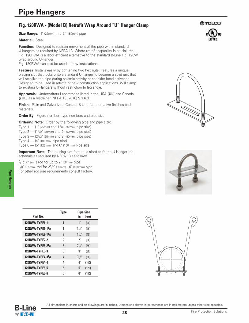
Fig. 120RWA - (Model B) Retrofit Wrap Around “U” Hanger Clamp
Size Range: 1" (25mm) thru 6" (150mm) pipe
Material: Steel
Function: Designed to restrain movement of the pipe within standardU-hangers as required by NFPA 13. Where retrofit capability is crucial, theFig. 120RWA is a labor efficient alternative to the standard B-Line Fig. 120Wwrap around U-hanger.Fig. 120RWA can also be used in new installations.
Features Installs easily by tightening two hex nuts. Features a uniquebracing slot that locks onto a standard U-hanger to become a solid unit thatwill stabilize the pipe during seismic activity or sprinkler head activation.Designed to be used in retrofit or new construction applications. Will clampto existing U-Hangers without restriction to leg angle.
Approvals: Underwriters Laboratories listed in the USA (UL) and Canada(cUL) as a restrainer. NFPA 13 (2010) 9.3.6.3.
Finish: Plain and Galvanized. Contact B-Line for alternative finishes andmaterials.
Order By: Figure number, type numbers and pipe size
Ordering Note: Order by the following type and pipe size:Type 1 — (1" (25mm) and 11/4" (32mm) pipe size)Type 2 — (11/2" (40mm) and 2" (50mm) pipe size)Type 3 — (21/2" (65mm) and 3" (80mm) pipe size)Type 4 — (4" (100mm) pipe size)Type 6 — (5" (125mm) and 6" (150mm) pipe size)
Important Note: The bracing slot feature is sized to fit the U-Hanger rodschedule as required by NFPA 13 as follows:5/16" (7.9mm) rod for up to 2" (50mm) pipe3/8" (9.5mm) rod for 21/2" (65mm) - 6" (160mm) pipeFor other rod size requirements consult factory.
Type Pipe SizePart No. in. (mm)
120RWA-TYPE1-1 1 1" (20)
120RWA-TYPE1-11/4 1 11/4" (25)
120RWA-TYPE2-11/2 2 11/2" (40)
120RWA-TYPE2-2 2 2" (50)
120RWA-TYPE3-21/2 3 21/2" (65)
120RWA-TYPE3-3 3 3" (80)
120RWA-TYPE4-31/2 4 31/2" (90)
120RWA-TYPE4-4 4 4" (100)
120RWA-TYPE6-5 6 5" (125)
120RWA-TYPE6-6 6 6" (150)
All dimensions in charts and on drawings are in inches. Dimensions shown in parentheses are in millimeters unless otherwise specified.
Pipe Hangers
Fire Protection Solutions28
Pipe Clamps
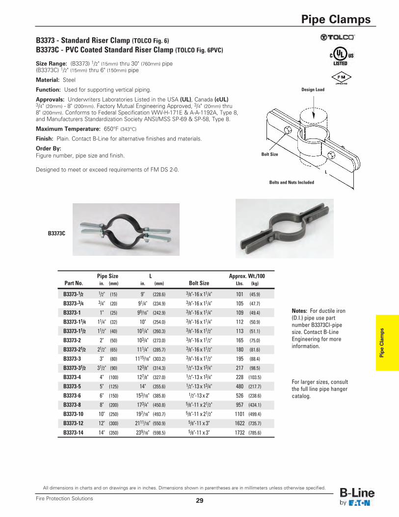
B3373 - Standard Riser Clamp (TOLCO Fig. 6)B3373C - PVC Coated Standard Riser Clamp (TOLCO Fig. 6PVC)
Bolts and Nuts Included
Bolt Size
L
Pipe Size L Approx. Wt./100Part No. in. (mm) in. (mm) Bolt Size Lbs. (kg)
B3373-1/2 1/2" (15) 9" (228.6) 3/8"-16 x 11/4" 101 (45.9)
B3373-3/4 3/4" (20) 91/4" (234.9) 3/8"-16 x 11/4" 105 (47.7)
B3373-1 1" (25) 99/16" (242.9) 3/8"-16 x 11/4" 109 (49.4)
B3373-11/4 11/4" (32) 10" (254.0) 3/8"-16 x 11/4" 112 (50.9)
B3373-11/2 11/2" (40) 101/4" (260.3) 3/8"-16 x 11/2" 113 (51.1)
B3373-2 2" (50) 103/4" (273.0) 3/8"-16 x 11/2" 165 (75.0)
B3373-21/2 21/2" (65) 111/4" (285.7) 3/8"-16 x 11/2" 180 (81.6)
B3373-3 3" (80) 1115/16" (303.2) 3/8"-16 x 11/2" 195 (88.4)
B3373-31/2 31/2" (90) 123/8" (314.3) 1/2"-13 x 13/4" 217 (98.5)
B3373-4 4" (100) 127/8" (327.0) 1/2"-13 x 13/4" 228 (103.5)
B3373-5 5" (125) 14" (355.6) 1/2"-13 x 13/4" 480 (217.7)
B3373-6 6" (150) 153/16" (385.8) 1/2"-13 x 2" 526 (238.6)
B3373-8 8" (200) 173/4" (450.8) 5/8"-11 x 21/2" 957 (434.1)
B3373-10 10" (250) 197/16" (493.7) 5/8"-11 x 21/2" 1101 (499.4)
B3373-12 12" (300) 2111/16" (550.9) 5/8"-11 x 3" 1622 (735.7)
B3373-14 14" (350) 239/16" (598.5) 5/8"-11 x 3" 1732 (785.6)
B3373C
Design Load
Size Range: (B3373) 1/2" (15mm) thru 30" (760mm) pipe(B3373C) 1/2" (15mm) thru 6" (150mm) pipe
Material: Steel
Function: Used for supporting vertical piping.
Approvals: Underwriters Laboratories Listed in the USA (UL), Canada (cUL)3/4" (20mm) - 8" (200mm). Factory Mutual Engineering Approved, 3/4" (20mm) thru8" (200mm). Conforms to Federal Specification WW-H-171E & A-A-1192A, Type 8,and Manufacturers Standardization Society ANSI/MSS SP-69 & SP-58, Type 8.
Maximum Temperature: 650°F (343°C)
Finish: Plain. Contact B-Line for alternative finishes and materials.
Order By:Figure number, pipe size and finish.
Designed to meet or exceed requirements of FM DS 2-0.
Notes: For ductile iron(D.I.) pipe use partnumber B3373CI-pipesize. Contact B-LineEngineering for moreinformation.
For larger sizes, consultthe full line pipe hangercatalog.
All dimensions in charts and on drawings are in inches. Dimensions shown in parentheses are in millimeters unless otherwise specified.
Pipe Clamps
29Fire Protection Solutions
Pipe Clam
ps
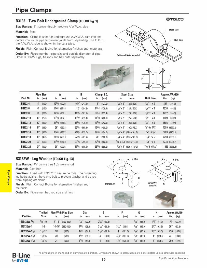
Size Range: 4" (100mm) thru 24" (600mm) A.W.W.A. pipe
Material: Steel
Function: Clamp is used for underground A.W.W.A. cast iron andductile iron water pipe to prevent joints from separating. The O.D. ofthe A.W.W.A. pipe is shown in the data table.
Finish: Plain. Contact B-Line for alternative finishes and materials.
Order By: Figure number, pipe size and outside diameter of pipe.Order B3132W lugs, tie rods and hex nuts separately.
Size Range: 3/4" (20mm) thru 11/2" (40mm) rodMaterial: Cast IronFunction: Used with B3132 to secure tie rods. The projecting lug bears against the clamp bolt to prevent washer and tie rodfrom slipping off clamp.Finish: Plain. Contact B-Line for alternative finishes andmaterials.Order By: Figure number, rod size and finish
B3132W - Lug Washer (TOLCO Fig. 9X)
Bolts and Nuts Included
Steel Size
Bolt Size
D Dia.
B3132W-3/4 B3132W-1thru 11/2
D Dia.E E
H H
GG
F
A
B
Pipe Size A B Clamp I.D. Steel Size Approx. Wt./100Part No. in. (mm) in. (mm) in. (mm) in. (mm) in. (mm) Bolt Size Lbs. (kg)
B3132-4 4" (100) 127/8" (327.0) 93/4" (247.6) 5" (127.0) 1/2" x 2" (12.7 x 50.8) 5/8"-11 x 3" 864 (391.9)
B3132-6 6" (150) 143/4" (374.6) 12" (304.8) 71/16" (179.4) 1/2" x 2" (12.7 x 50.8) 5/8"-11 x 3" 1020 (462.6)
B3132-8 8" (200) 171/4" (438.1) 141/4" (361.9) 93/16" (233.4) 1/2" x 2" (12.7 x 50.8) 5/8"-11 x 3" 1222 (554.3)
B3132-10 10" (250) 193/8" (492.1) 161/2" (419.1) 113/8" (288.9) 1/2" x 2" (12.7 x 50.8) 5/8"-11 x 3" 1409 (639.1)
B3132-12 12" (300) 217/8" (555.6) 187/8" (479.4) 131/2" (342.9) 1/2" x 2" (12.7 x 50.8) 5/8"-11 x 3" 1608 (729.4)
B3132-14 14" (350) 26" (660.4) 221/4" (565.1) 153/4" (400.0) 3/4" x 3" (19.0 x 76.2) 7/8"-9 x 41/2" 4359 (1977.2)
B3132-16 16" (400) 283/8" (720.7) 245/8" (625.5) 177/8" (454.0) 3/4" x 4" (19.0 x 101.6) 1"-8 x 41/2" 6403 (2904.4)
B3132-18 18" (450) 313/8" (796.9) 275/8" (701.7) 20" (508.0) 3/4" x 4" (19.0 x 101.6) 11/4"-7 x 5" 7293 (3308.1)
B3132-20 20" (500) 331/2" (850.9) 293/4" (755.6) 221/8" (562.0) 3/4" x 41/2" (19.0 x 114.3) 11/4"-7 x 5" 8778 (3981.7)
B3132-24 24" (600) 39" (990.6) 351/4" (895.3) 263/8" (669.9) 3/4" x 5" (19.0 x 127.0) 11/4"-6 x 51/2" 11659 (5288.5)
Tie Rod Use With Pipe Size Dia. E F G H Approx. Wt./100Part No. Size in. (mm) in. (mm) in. (mm) in. (mm) in. (mm) in. (mm) Lbs. (kg)
B3132W-3/4 3/4"-10 4"-12" (100-300) 7/8" (22.2) 23/8" (60.3) -- -- 5/8" (15.9) 15/8" (41.3) 74 (33.7)
B3132W-1 1"-8 14"-16" (350-400) 11/8" (28.6) 31/2" (88.9) 31/2" (88.9) 5/8" (15.9) 21/2" (63.5) 207 (93.9)
B3132W-11/4 11/4"-7 18" (450) 13/8" (34.9) 31/2" (88.9) 4" (101.6) 5/8" (15.9) 31/2" (63.5) 236 (107.0)
B3132W-13/8 13/8"-6 20" (500) 11/2" (38.1) 4" (101.6) 41/4" (107.9) 5/8" (15.9) 4" (101.6) 231 (104.8)
B3132W-11/2 11/2"-6 24" (600) 15/8" (41.3) 4" (101.6) 43/4" (120.6) 5/8" (15.9) 4" (101.6) 259 (117.5)
B3132 - Two-Bolt Underground Clamp (TOLCO Fig. 9)
All dimensions in charts and on drawings are in inches. Dimensions shown in parentheses are in millimeters unless otherwise specified.
Pipe Clamps
Fire Protection Solutions30
Pipe Clamps
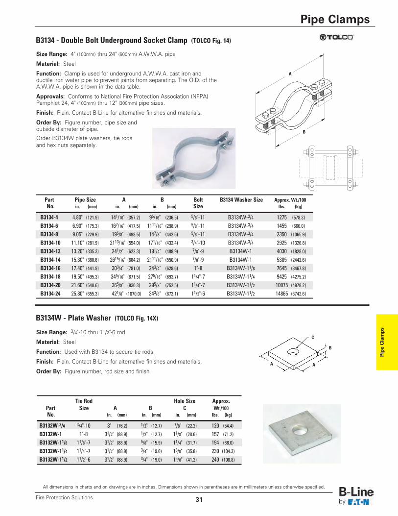
B3134 - Double Bolt Underground Socket Clamp (TOLCO Fig. 14)
Size Range: 4" (100mm) thru 24" (600mm) A.W.W.A. pipe
Material: Steel
Function: Clamp is used for underground A.W.W.A. cast iron andductile iron water pipe to prevent joints from separating. The O.D. of theA.W.W.A. pipe is shown in the data table.
Approvals: Conforms to National Fire Protection Association (NFPA)Pamphlet 24, 4" (100mm) thru 12" (300mm) pipe sizes.
Finish: Plain. Contact B-Line for alternative finishes and materials.
Order By: Figure number, pipe size andoutside diameter of pipe.
Order B3134W plate washers, tie rodsand hex nuts separately.
A
B
Part Pipe Size A B Bolt B3134 Washer Size Approx. Wt./100No. in. (mm) in. (mm) in. (mm) Size lbs. (kg)
B3134-4 4.80" (121.9) 141/16" (357.2) 95/16" (236.5) 5/8"-11 B3134W-3/4 1275 (578.3)
B3134-6 6.90" (175.3) 167/16" (417.5) 1111/16" (298.9) 5/8"-11 B3134W-3/4 1455 (660.0)
B3134-8 9.05" (229.9) 195/8" (498.5) 147/8" (442.6) 5/8"-11 B3134W-3/4 2350 (1065.9)
B3134-10 11.10" (281.9) 2113/16" (554.0) 171/16" (433.4) 3/4"-10 B3134W-3/4 2925 (1326.8)
B3134-12 13.20" (335.3) 241/2" (622.3) 191/4" (488.9) 7/8"-9 B3134W-1 4030 (1828.0)
B3134-14 15.30" (388.6) 2615/16" (684.2) 2111/16" (550.9) 7/8"-9 B3134W-1 5385 (2442.6)
B3134-16 17.40" (441.9) 303/4" (781.0) 243/4" (628.6) 1"-8 B3134W-11/8 7645 (3467.8)
B3134-18 19.50" (495.3) 345/16" (871.5) 275/16" (693.7) 11/4"-7 B3134W-11/4 9425 (4275.2)
B3134-20 21.60" (548.6) 365/8" (930.3) 295/8" (752.5) 11/4"-7 B3134W-11/2 10975 (4978.2)B3134-24 25.80" (655.3) 421/8" (1070.0) 343/8" (873.1) 11/2"-6 B3134W-11/2 14865 (6742.6)
Tie Rod Hole Size Approx.Part Size A B C Wt./100No. in. (mm) in. (mm) in. (mm) lbs. (kg)
B3132W-3/4 3/4"-10 3" (76.2) 1/2" (12.7) 7/8" (22.2) 120 (54.4)B3132W-1 1"-8 31/2" (88.9) 1/2" (12.7) 11/8" (28.6) 157 (71.2)B3132W-11/8 11/8"-7 31/2" (88.9) 5/8" (15.9) 11/4" (31.7) 194 (88.0)B3132W-11/4 11/4"-7 31/2" (88.9) 3/4" (19.0) 13/8" (35.8) 230 (104.3)B3132W-11/2 11/2"-6 31/2" (88.9) 3/4" (19.0) 15/8" (41.2) 240 (108.8)
B3134W - Plate Washer (TOLCO Fig. 14X)
Size Range: 3/4"-10 thru 11/2"-6 rod
Material: Steel
Function: Used with B3134 to secure tie rods.
Finish: Plain. Contact B-Line for alternative finishes and materials.
Order By: Figure number, rod size and finish
C
A A
B
All dimensions in charts and on drawings are in inches. Dimensions shown in parentheses are in millimeters unless otherwise specified.
Pipe Clamps
31Fire Protection Solutions
Pipe Clam
ps
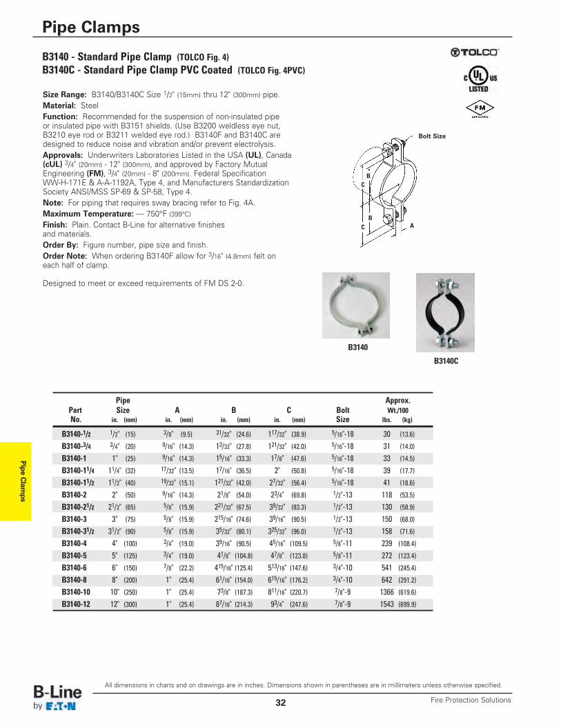
B3140 - Standard Pipe Clamp (TOLCO Fig. 4)B3140C - Standard Pipe Clamp PVC Coated (TOLCO Fig. 4PVC)
Size Range: B3140/B3140C Size 1/2" (15mm) thru 12" (300mm) pipe.Material: SteelFunction: Recommended for the suspension of non-insulated pipeor insulated pipe with B3151 shields. (Use B3200 weldless eye nut,B3210 eye rod or B3211 welded eye rod.) B3140F and B3140C aredesigned to reduce noise and vibration and/or prevent electrolysis.Approvals: Underwriters Laboratories Listed in the USA (UL), Canada(cUL) 3/4" (20mm) - 12" (300mm), and approved by Factory MutualEngineering (FM), 3/4" (20mm) - 8" (200mm). Federal SpecificationWW-H-171E & A-A-1192A, Type 4, and Manufacturers StandardizationSociety ANSI/MSS SP-69 & SP-58, Type 4. Note: For piping that requires sway bracing refer to Fig. 4A.Maximum Temperature: — 750°F (399°C)Finish: Plain. Contact B-Line for alternative finishesand materials.Order By: Figure number, pipe size and finish.Order Note: When ordering B3140F allow for 3/16" (4.8mm) felt oneach half of clamp.
Designed to meet or exceed requirements of FM DS 2-0.
C
C
A
Bolt Size
B
B
Pipe Approx.Part Size A B C Bolt Wt./100No. in. (mm) in. (mm) in. (mm) in. (mm) Size lbs. (kg)
B3140-1/2 1/2" (15) 3/8" (9.5) 31/32" (24.6) 117/32" (38.9) 5/16"-18 30 (13.6)
B3140-3/4 3/4" (20) 9/16" (14.3) 13/32" (27.8) 121/32" (42.0) 5/16"-18 31 (14.0)
B3140-1 1" (25) 9/16" (14.3) 15/16" (33.3) 17/8" (47.6) 5/16"-18 33 (14.5)
B3140-11/4 11/4" (32) 17/32" (13.5) 17/16" (36.5) 2" (50.8) 5/16"-18 39 (17.7)
B3140-11/2 11/2" (40) 19/32" (15.1) 121/32" (42.0) 27/32" (56.4) 5/16"-18 41 (18.6)
B3140-2 2" (50) 9/16" (14.3) 21/8" (54.0) 23/4" (69.8) 1/2"-13 118 (53.5)
B3140-21/2 21/2" (65) 5/8" (15.9) 221/32" (67.5) 39/32" (83.3) 1/2"-13 130 (58.9)
B3140-3 3" (75) 5/8" (15.9) 215/16" (74.6) 39/16" (90.5) 1/2"-13 150 (68.0)
B3140-31/2 31/2" (90) 5/8" (15.9) 35/32" (80.1) 325/32" (96.0) 1/2"-13 158 (71.6)
B3140-4 4" (100) 3/4" (19.0) 39/16" (90.5) 45/16" (109.5) 5/8"-11 239 (108.4)
B3140-5 5" (125) 3/4" (19.0) 41/8" (104.8) 47/8" (123.8) 5/8"-11 272 (123.4)
B3140-6 6" (150) 7/8" (22.2) 415/16" (125.4) 513/16" (147.6) 3/4"-10 541 (245.4)
B3140-8 8" (200) 1" (25.4) 61/16" (154.0) 615/16" (176.2) 3/4"-10 642 (291.2)
B3140-10 10" (250) 1" (25.4) 73/8" (187.3) 811/16" (220.7) 7/8"-9 1366 (619.6)B3140-12 12" (300) 1" (25.4) 87/16" (214.3) 93/4" (247.6) 7/8"-9 1543 (699.9)
B3140
B3140C
All dimensions in charts and on drawings are in inches. Dimensions shown in parentheses are in millimeters unless otherwise specified.
Pipe Clamps
Fire Protection Solutions32
Pipe Clamps
All dimensions in charts and on drawings are in inches. Dimensions shown in parentheses are in millimeters unless otherwise specified.
Pipe Clamps
33Fire Protection Solutions
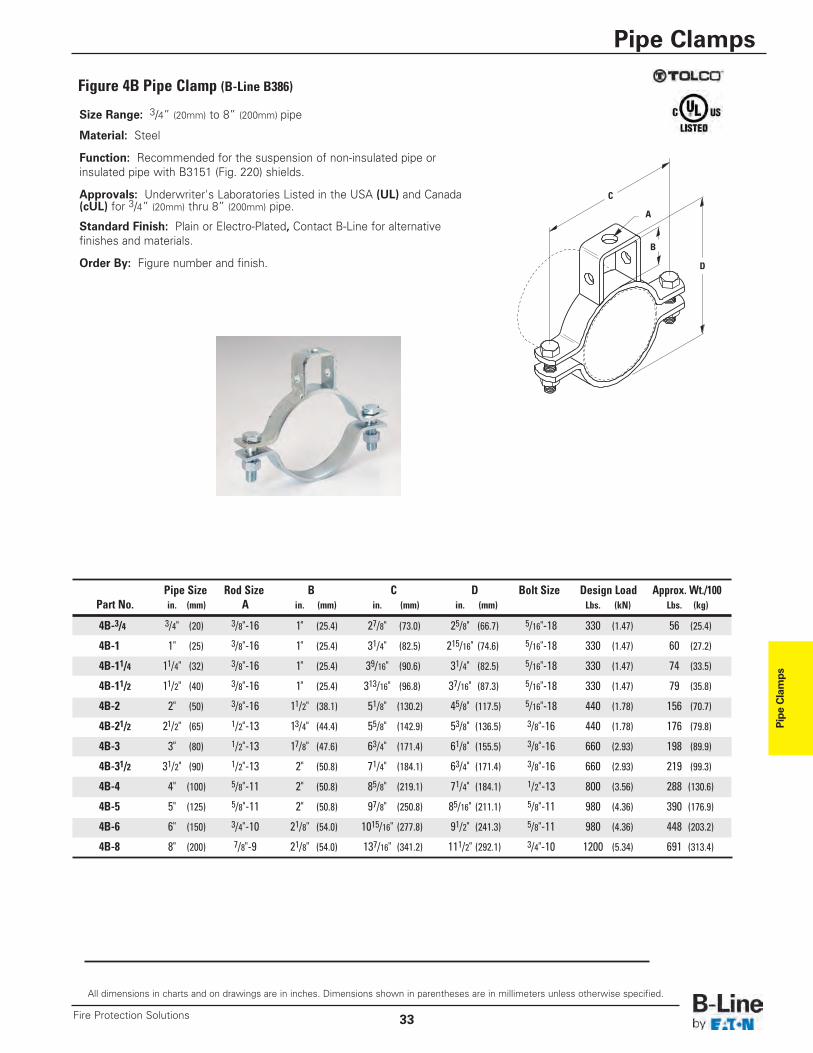
Size Range: 3/4” (20mm) to 8” (200mm) pipe
Material: Steel
Function: Recommended for the suspension of non-insulated pipe orinsulated pipe with B3151 (Fig. 220) shields.
Approvals: Underwriter's Laboratories Listed in the USA (UL) and Canada(cUL) for 3/4” (20mm) thru 8” (200mm) pipe.
Standard Finish: Plain or Electro-Plated, Contact B-Line for alternativefinishes and materials.
Order By: Figure number and finish.
Figure 4B Pipe Clamp (B-Line B386)
Pipe Size Rod Size B C D Bolt Size Design Load Approx. Wt./100Part No. in. (mm) A in. (mm) in. (mm) in. (mm) Lbs. (kN) Lbs. (kg)
4B-3/4 3/4" (20) 3/8"-16 1" (25.4) 27/8" (73.0) 25/8" (66.7) 5/16"-18 330 (1.47) 56 (25.4)
4B-1 1" (25) 3/8"-16 1" (25.4) 31/4" (82.5) 215/16" (74.6) 5/16"-18 330 (1.47) 60 (27.2)
4B-11/4 11/4" (32) 3/8"-16 1" (25.4) 39/16" (90.6) 31/4" (82.5) 5/16"-18 330 (1.47) 74 (33.5)
4B-11/2 11/2" (40) 3/8"-16 1" (25.4) 313/16" (96.8) 37/16" (87.3) 5/16"-18 330 (1.47) 79 (35.8)
4B-2 2" (50) 3/8"-16 11/2" (38.1) 51/8" (130.2) 45/8" (117.5) 5/16"-18 440 (1.78) 156 (70.7)
4B-21/2 21/2" (65) 1/2"-13 13/4" (44.4) 55/8" (142.9) 53/8" (136.5) 3/8"-16 440 (1.78) 176 (79.8)
4B-3 3" (80) 1/2"-13 17/8" (47.6) 63/4" (171.4) 61/8" (155.5) 3/8"-16 660 (2.93) 198 (89.9)
4B-31/2 31/2" (90) 1/2"-13 2" (50.8) 71/4" (184.1) 63/4" (171.4) 3/8"-16 660 (2.93) 219 (99.3)
4B-4 4" (100) 5/8"-11 2" (50.8) 85/8" (219.1) 71/4" (184.1) 1/2"-13 800 (3.56) 288 (130.6)
4B-5 5" (125) 5/8"-11 2" (50.8) 97/8" (250.8) 85/16" (211.1) 5/8"-11 980 (4.36) 390 (176.9)
4B-6 6" (150) 3/4"-10 21/8" (54.0) 1015/16" (277.8) 91/2" (241.3) 5/8"-11 980 (4.36) 448 (203.2)
4B-8 8" (200) 7/8"-9 21/8" (54.0) 137/16" (341.2) 111/2" (292.1) 3/4"-10 1200 (5.34) 691 (313.4)
B
D
C
A
Pipe Clam
ps
All dimensions in charts and on drawings are in inches. Dimensions shown in parentheses are in millimeters unless otherwise specified.
Pipe Clamps
Fire Protection Solutions34
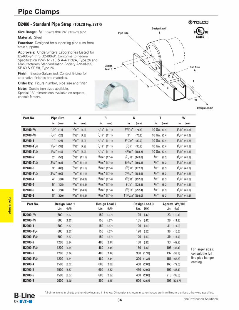
B2400 - Standard Pipe Strap (TOLCO Fig. 2STR)
Part No. Pipe Size A B C T Win. (mm) in. (mm) in. (mm) in. (mm) in. (mm) in. (mm)
B2400-1/2 1/2” (15) 5/16” (7.9) 7/16” (11.1) 213/16” (71.4) 10 Ga. (3.4) 15/8” (41.3)
B2400-3/4 3/4” (20) 5/16” (7.9) 7/16” (11.1) 3” (76.2) 10 Ga. (3.4) 15/8” (41.3)
B2400-1 1” (25) 5/16” (7.9) 7/16” (11.1) 317/32” (89.7) 10 Ga. (3.4) 15/8” (41.3)
B2400-11/4 11/4” (32) 5/16” (7.9) 7/16” (11.1) 33/4” (95.2) 10 Ga. (3.4) 15/8” (41.3)
B2400-11/2 11/2” (40) 5/16” (7.9) 7/16” (11.1) 41/16” (103.2) 10 Ga. (3.4) 15/8” (41.3)
B2400-2 2” (50) 7/16” (11.1) 11/16” (17.4) 521/32” (143.6) 1/4” (6.3) 15/8” (41.3)
B2400-21/2 21/2” (65) 7/16” (11.1) 11/16” (17.4) 65/32” (156.3) 1/4” (6.3) 15/8” (41.3)
B2400-3 3” (80) 7/16” (11.1) 11/16” (17.4) 625/32” (172.2) 1/4” (6.3) 15/8” (41.3)
B2400-31/2 31/2” (90) 7/16” (11.1) 11/16” (17.4) 79/32” (184.9) 1/4” (6.3) 15/8” (41.3)
B2400-4 4” (100) 9/16” (14.3) 11/16” (17.4) 725/32” (197.6) 1/4” (6.3) 15/8” (41.3)
B2400-5 5” (125) 9/16” (14.3) 11/16” (17.4) 87/8” (225.4) 1/4” (6.3) 15/8” (41.3)
B2400-6 6” (150) 9/16” (14.3) 11/16” (17.4) 915/16” (252.4) 1/4” (6.3) 15/8” (41.3)
B2400-8 8” (200) 9/16” (14.3) 11/16” (17.4) 1131/32” (304.0) 1/4” (6.3) 15/8” (41.3)
Bolt SizeA
B
T
C
W
Design Load 2
DesignLoad 3
Design Load 1
Pipe SizeSize Range: 1/2" (15mm) thru 24" (600mm) pipe
Material: Steel
Function: Designed for supporting pipe runs fromstrut supports.
Approvals: Underwriters Laboratories Listed forB2400-3/4" thru B2400-8". Conforms to FederalSpecification WW-H-171E & A-A-1192A, Type 26 andManufacturers Standardization Society ANSI/MSSSP-69 & SP-58, Type 26.
Finish: Electro-Galvanized. Contact B-Line foralternative finishes and materials.
Order By: Figure number, pipe size and finish
Note: Ductile iron sizes available.Special “B” dimensions available on request,consult factory.
Part No. Design Load 1 Design Load 2 Design Load 3 Approx. Wt./100Lbs. (kN) Lbs. (kN) Lbs. (kN) Lbs. (kg)
B2400-1/2 600 (2.67) 150 (.67) 105 (.47) 23 (10.4)
B2400-3/4 600 (2.67) 150 (.67) 105 (.47) 26 (11.8)
B2400-1 600 (2.67) 150 (.67) 120 (.53) 31 (14.0)
B2400-11/4 600 (2.67) 150 (.67) 120 (.53) 36 (16.3)
B2400-11/2 600 (2.67) 150 (.67) 120 (.53) 39 (17.7)
B2400-2 1200 (5.34) 480 (2.14) 180 (.80) 93 (42.2)
B2400-21/2 1200 (5.34) 480 (2.14) 180 (.80) 106 (48.1)
B2400-3 1200 (5.34) 480 (2.14) 300 (1.33) 132 (59.9)
B2400-31/2 1200 (5.34) 480 (2.14) 300 (1.33) 151 (68.5)
B2400-4 1500 (6.67) 600 (2.67) 450 (2.00) 160 (72.6)
B2400-5 1500 (6.67) 600 (2.67) 450 (2.00) 192 (87.1)
B2400-6 1500 (6.67) 600 (2.67) 450 (2.00) 219 (99.3)
B2400-8 2000 (8.90) 800 (3.56) 600 (2.67) 297 (134.7)
For larger sizes,consult the fullline pipe hangercatalog.
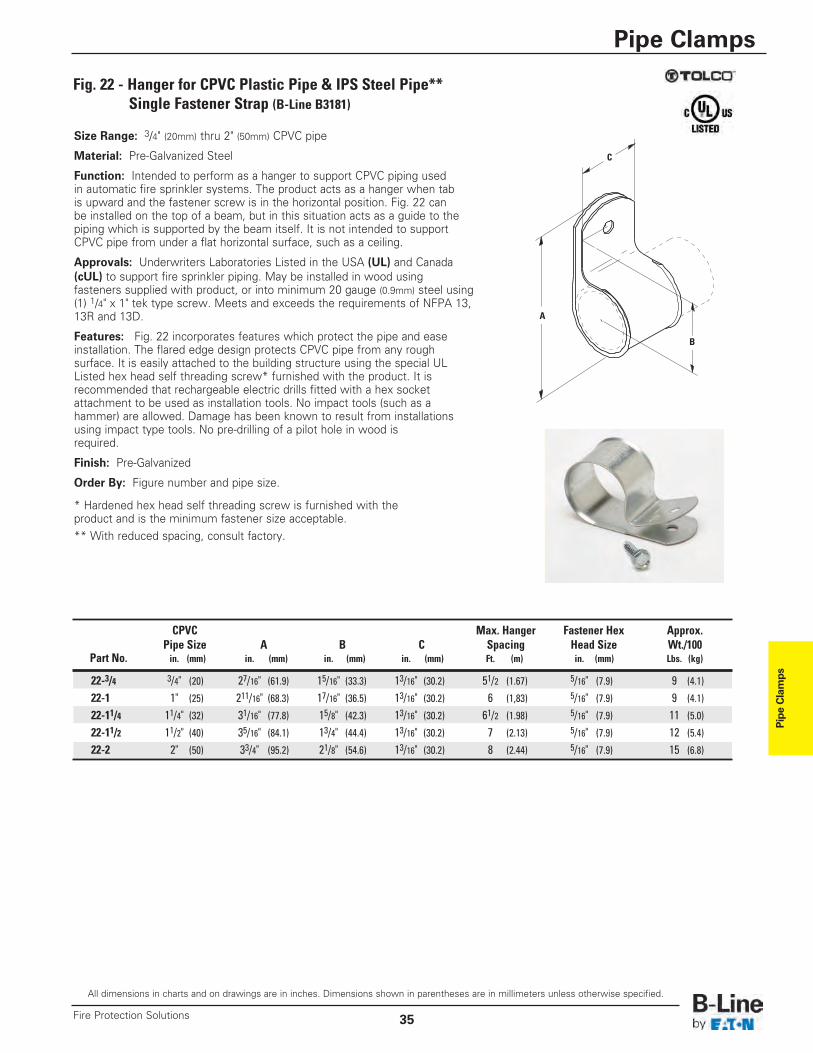
Pipe Clamps
All dimensions in charts and on drawings are in inches. Dimensions shown in parentheses are in millimeters unless otherwise specified.
Pipe Clamps
35Fire Protection Solutions
Fig. 22 - Hanger for CPVC Plastic Pipe & IPS Steel Pipe**Single Fastener Strap (B-Line B3181)
Size Range: 3/4" (20mm) thru 2" (50mm) CPVC pipe
Material: Pre-Galvanized Steel
Function: Intended to perform as a hanger to support CPVC piping usedin automatic fire sprinkler systems. The product acts as a hanger when tabis upward and the fastener screw is in the horizontal position. Fig. 22 canbe installed on the top of a beam, but in this situation acts as a guide to thepiping which is supported by the beam itself. It is not intended to supportCPVC pipe from under a flat horizontal surface, such as a ceiling.
Approvals: Underwriters Laboratories Listed in the USA (UL) and Canada(cUL) to support fire sprinkler piping. May be installed in wood usingfasteners supplied with product, or into minimum 20 gauge (0.9mm) steel using(1) 1/4" x 1" tek type screw. Meets and exceeds the requirements of NFPA 13,13R and 13D.
Features: Fig. 22 incorporates features which protect the pipe and easeinstallation. The flared edge design protects CPVC pipe from any roughsurface. It is easily attached to the building structure using the special ULListed hex head self threading screw* furnished with the product. It isrecommended that rechargeable electric drills fitted with a hex socketattachment to be used as installation tools. No impact tools (such as ahammer) are allowed. Damage has been known to result from installationsusing impact type tools. No pre-drilling of a pilot hole in wood isrequired.
Finish: Pre-Galvanized
Order By: Figure number and pipe size.
* Hardened hex head self threading screw is furnished with theproduct and is the minimum fastener size acceptable.** With reduced spacing, consult factory.
C
A
B
CPVC Max. Hanger Fastener Hex Approx.Pipe Size A B C Spacing Head Size Wt./100
Part No. in. (mm) in. (mm) in. (mm) in. (mm) Ft. (m) in. (mm) Lbs. (kg)
22-3/4 3/4" (20) 27/16" (61.9) 15/16" (33.3) 13/16" (30.2) 51/2 (1.67) 5/16" (7.9) 9 (4.1)
22-1 1" (25) 211/16" (68.3) 17/16" (36.5) 13/16" (30.2) 6 (1,83) 5/16" (7.9) 9 (4.1)
22-11/4 11/4" (32) 31/16" (77.8) 15/8" (42.3) 13/16" (30.2) 61/2 (1.98) 5/16" (7.9) 11 (5.0)22-11/2 11/2" (40) 35/16" (84.1) 13/4" (44.4) 13/16" (30.2) 7 (2.13) 5/16" (7.9) 12 (5.4)22-2 2" (50) 33/4" (95.2) 21/8" (54.6) 13/16" (30.2) 8 (2.44) 5/16" (7.9) 15 (6.8)
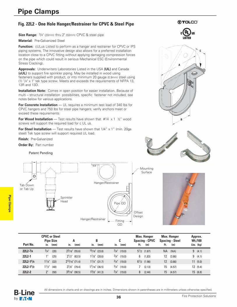
Pipe Clam
ps
All dimensions in charts and on drawings are in inches. Dimensions shown in parentheses are in millimeters unless otherwise specified.
Pipe Clamps
Fire Protection Solutions36
Fig. 22L2 - One Hole Hanger/Restrainer for CPVC & Steel Pipe
Size Range: 3/4" (20mm) thru 2" (50mm) CPVC & steel pipe
Material: Pre-Galvanized Steel
Function: cULus Listed to perform as a hanger and restrainer for CPVC or IPSpiping systems. The innovative design also allows for a preferred installationlocation close to a CPVC fitting without applying damaging compression forceson the pipe which could result in serious Mechanical ESC (EnvironmentalStress Cracking).
Approvals: Underwriters Laboratories Listed in the USA (UL) and Canada(cUL) to support fire sprinkler piping. May be installed in wood usingfasteners supplied with product, or into minimum 20 gauge (0.9mm) steel using(1) 1/4" x 1" tek type screw. Meets and exceeds the requirements of NFPA 13,13R and 13D.
Installation Note: Comes in open position for easier installation. Because ofmulti – structural installation possibilities, specific fastener not included; seenotes below for various applications.
For Concrete Installation — UL requires a minimum test load of 340 lbs forCPVC hangers and 750 lbs for steel pipe hangers; verify anchors meet orexceed these requirements.
For Wood Installation — Test results have shown that #14 x 1 ½” woodscrews will support the required load for c UL us.
For Steel Installation — Test results have shown that 1/4” x 1” (min. 20gasteel) Tek type screw will support required UL load.
Finish: Pre-Galvanized
Order By: Part number
C
A
B
CPVC or Steel Max. Hanger Max. Hanger Approx.Pipe Size A B C Spacing - CPVC Spacing - Steel Wt./100
Part No. in. (mm) in. (mm) in. (mm) in. (mm) Ft. (m) Ft. (m) Lbs. (kg)
22L2-3/4 3/4" (20) 23/16" (55.6) 15/16" (23.8) 3/4" (19.0) 51/2 (1.67) NA (NA) 9 (4.1)
22L2-1 1" (25) 21/2" (63.5) 11/8" (28.6) 3/4" (19.0) 6 (1,83) 12 (3.66) 9 (4.1)
22L2-11/4 11/4" (32) 213/16" (71.4) 11/4" (31.7) 3/4" (19.0) 61/2 (1.98) 12 (3.66) 11 (5.0)
22L2-11/2 11/2" (40) 31/8" (79.4) 17/16" (36.5) 3/4" (19.0) 7 (2.13) 15 (4.57) 12 (5.4)
22L2-2 2" (50) 39/16" (90.5) 15/8" (41.3) 3/4" (19.0) 8 (2.44) 15 (4.57) 15 (6.8)
TAB DOWNor TAB UP
SPRINKLERHEAD
HANGER/RESTRAINER
FITTING OD
MOUNTING SURFACE
PIPE OD
HANGER/RESTRAINER
OFFSETDESIGN
Tab Downor Tab Up
SprinklerHead
Hanger/Restrainer
Hanger/Restrainer FittingOD
Pipe OD
MountingSurface
OffsetDesign
Patent Pending
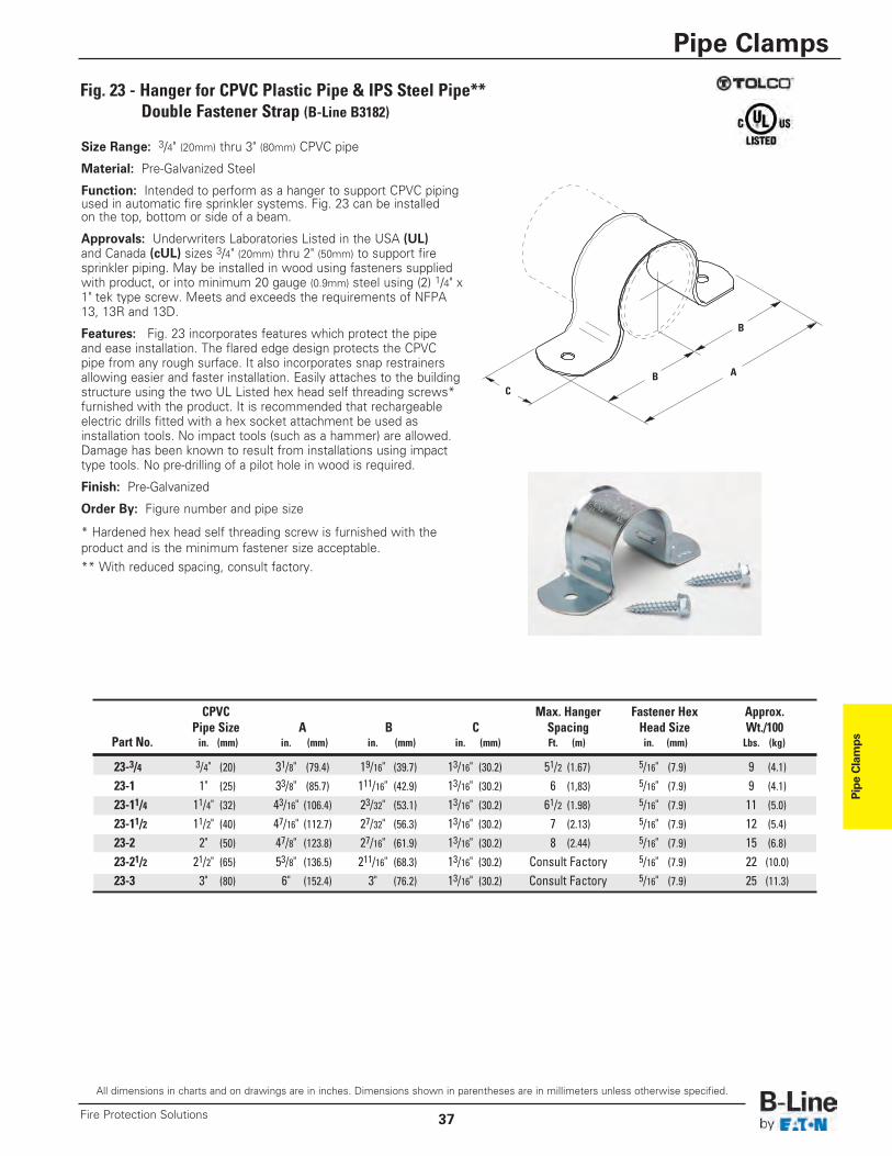
Pipe Clamps
All dimensions in charts and on drawings are in inches. Dimensions shown in parentheses are in millimeters unless otherwise specified.
Pipe Clamps
37Fire Protection Solutions
Fig. 23 - Hanger for CPVC Plastic Pipe & IPS Steel Pipe**Double Fastener Strap (B-Line B3182)
Size Range: 3/4" (20mm) thru 3" (80mm) CPVC pipe
Material: Pre-Galvanized Steel
Function: Intended to perform as a hanger to support CPVC pipingused in automatic fire sprinkler systems. Fig. 23 can be installedon the top, bottom or side of a beam.
Approvals: Underwriters Laboratories Listed in the USA (UL)and Canada (cUL) sizes 3/4" (20mm) thru 2" (50mm) to support firesprinkler piping. May be installed in wood using fasteners suppliedwith product, or into minimum 20 gauge (0.9mm) steel using (2) 1/4" x1" tek type screw. Meets and exceeds the requirements of NFPA13, 13R and 13D.
Features: Fig. 23 incorporates features which protect the pipeand ease installation. The flared edge design protects the CPVCpipe from any rough surface. It also incorporates snap restrainersallowing easier and faster installation. Easily attaches to the buildingstructure using the two UL Listed hex head self threading screws*furnished with the product. It is recommended that rechargeableelectric drills fitted with a hex socket attachment be used asinstallation tools. No impact tools (such as a hammer) are allowed.Damage has been known to result from installations using impacttype tools. No pre-drilling of a pilot hole in wood is required.
Finish: Pre-Galvanized
Order By: Figure number and pipe size
* Hardened hex head self threading screw is furnished with theproduct and is the minimum fastener size acceptable.** With reduced spacing, consult factory.
A
CB
B
CPVC Max. Hanger Fastener Hex Approx.Pipe Size A B C Spacing Head Size Wt./100
Part No. in. (mm) in. (mm) in. (mm) in. (mm) Ft. (m) in. (mm) Lbs. (kg)
23-3/4 3/4" (20) 31/8" (79.4) 19/16" (39.7) 13/16" (30.2) 51/2 (1.67) 5/16" (7.9) 9 (4.1)
23-1 1" (25) 33/8" (85.7) 111/16" (42.9) 13/16" (30.2) 6 (1,83) 5/16" (7.9) 9 (4.1)
23-11/4 11/4" (32) 43/16" (106.4) 23/32" (53.1) 13/16" (30.2) 61/2 (1.98) 5/16" (7.9) 11 (5.0)
23-11/2 11/2" (40) 47/16" (112.7) 27/32" (56.3) 13/16" (30.2) 7 (2.13) 5/16" (7.9) 12 (5.4)
23-2 2" (50) 47/8" (123.8) 27/16" (61.9) 13/16" (30.2) 8 (2.44) 5/16" (7.9) 15 (6.8)
23-21/2 21/2" (65) 53/8" (136.5) 211/16" (68.3) 13/16" (30.2) Consult Factory 5/16" (7.9) 22 (10.0)23-3 3" (80) 6" (152.4) 3" (76.2) 13/16" (30.2) Consult Factory 5/16" (7.9) 25 (11.3)
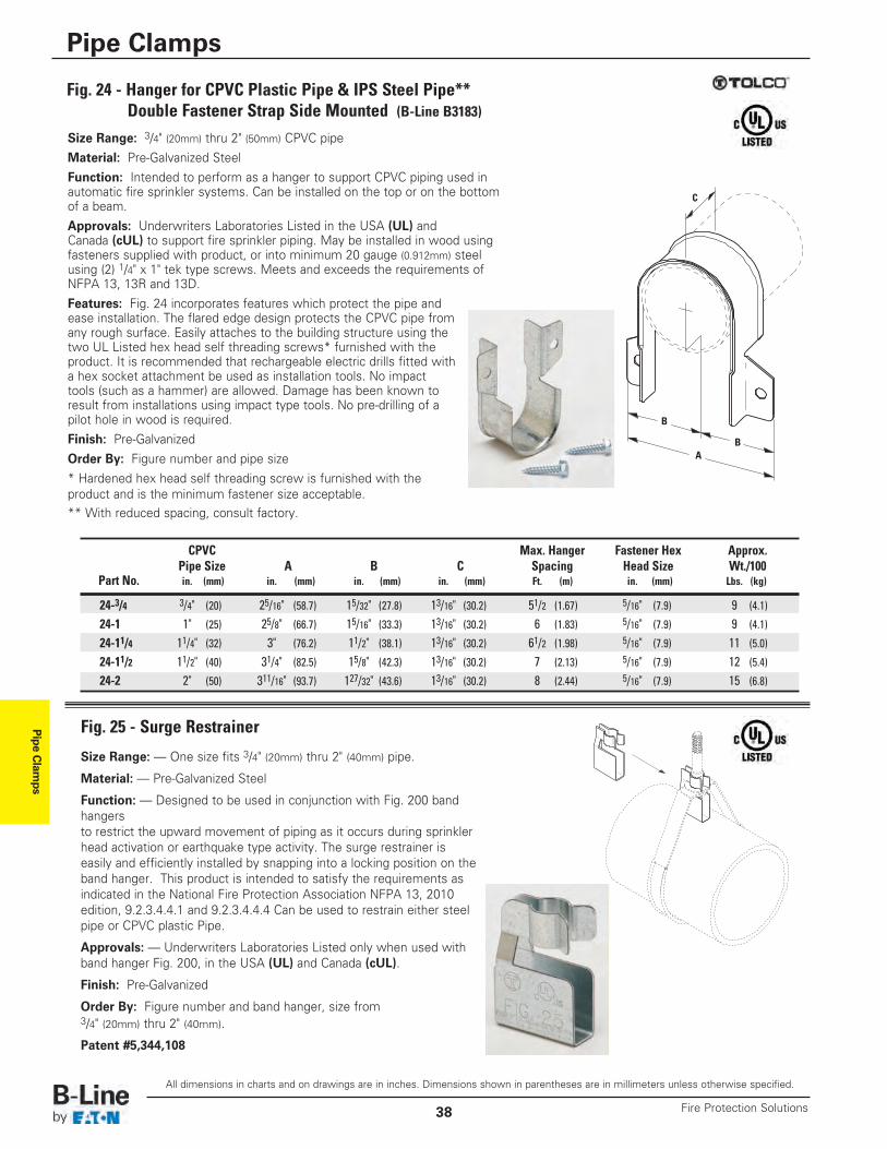
Pipe Clam
ps
All dimensions in charts and on drawings are in inches. Dimensions shown in parentheses are in millimeters unless otherwise specified.
Pipe Clamps
Fire Protection Solutions38
Fig. 24 - Hanger for CPVC Plastic Pipe & IPS Steel Pipe**Double Fastener Strap Side Mounted (B-Line B3183)
Size Range: 3/4" (20mm) thru 2" (50mm) CPVC pipeMaterial: Pre-Galvanized SteelFunction: Intended to perform as a hanger to support CPVC piping used inautomatic fire sprinkler systems. Can be installed on the top or on the bottomof a beam.Approvals: Underwriters Laboratories Listed in the USA (UL) andCanada (cUL) to support fire sprinkler piping. May be installed in wood usingfasteners supplied with product, or into minimum 20 gauge (0.912mm) steelusing (2) 1/4" x 1" tek type screws. Meets and exceeds the requirements ofNFPA 13, 13R and 13D.Features: Fig. 24 incorporates features which protect the pipe andease installation. The flared edge design protects the CPVC pipe fromany rough surface. Easily attaches to the building structure using the two UL Listed hex head self threading screws* furnished with theproduct. It is recommended that rechargeable electric drills fitted witha hex socket attachment be used as installation tools. No impacttools (such as a hammer) are allowed. Damage has been known toresult from installations using impact type tools. No pre-drilling of apilot hole in wood is required.Finish: Pre-GalvanizedOrder By: Figure number and pipe size* Hardened hex head self threading screw is furnished with theproduct and is the minimum fastener size acceptable.** With reduced spacing, consult factory.
C
A
B
B
CPVC Max. Hanger Fastener Hex Approx.Pipe Size A B C Spacing Head Size Wt./100
Part No. in. (mm) in. (mm) in. (mm) in. (mm) Ft. (m) in. (mm) Lbs. (kg)
24-3/4 3/4" (20) 25/16" (58.7) 15/32" (27.8) 13/16" (30.2) 51/2 (1.67) 5/16" (7.9) 9 (4.1)
24-1 1" (25) 25/8" (66.7) 15/16" (33.3) 13/16" (30.2) 6 (1.83) 5/16" (7.9) 9 (4.1)
24-11/4 11/4" (32) 3" (76.2) 11/2" (38.1) 13/16" (30.2) 61/2 (1.98) 5/16" (7.9) 11 (5.0)24-11/2 11/2" (40) 31/4" (82.5) 15/8" (42.3) 13/16" (30.2) 7 (2.13) 5/16" (7.9) 12 (5.4)24-2 2" (50) 311/16" (93.7) 127/32" (43.6) 13/16" (30.2) 8 (2.44) 5/16" (7.9) 15 (6.8)
Fig. 25 - Surge Restrainer
Size Range: — One size fits 3/4" (20mm) thru 2" (40mm) pipe.
Material: — Pre-Galvanized Steel
Function: — Designed to be used in conjunction with Fig. 200 bandhangersto restrict the upward movement of piping as it occurs during sprinklerhead activation or earthquake type activity. The surge restrainer iseasily and efficiently installed by snapping into a locking position on theband hanger. This product is intended to satisfy the requirements asindicated in the National Fire Protection Association NFPA 13, 2010edition, 9.2.3.4.4.1 and 9.2.3.4.4.4 Can be used to restrain either steelpipe or CPVC plastic Pipe.
Approvals: — Underwriters Laboratories Listed only when used withband hanger Fig. 200, in the USA (UL) and Canada (cUL).
Finish: Pre-Galvanized
Order By: Figure number and band hanger, size from3/4" (20mm) thru 2" (40mm).
Patent #5,344,108
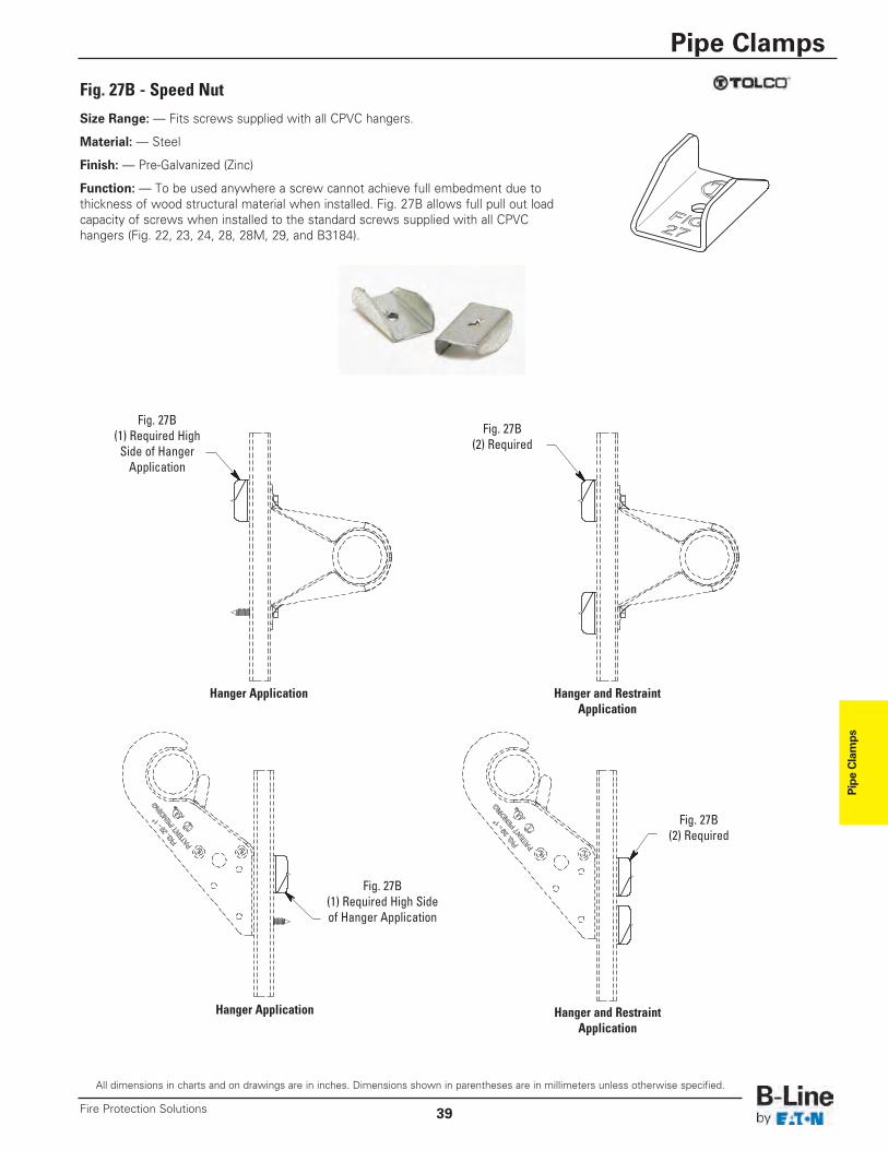
Pipe Clamps
All dimensions in charts and on drawings are in inches. Dimensions shown in parentheses are in millimeters unless otherwise specified.
Pipe Clamps
39Fire Protection Solutions
Fig. 27B - Speed Nut
Size Range: — Fits screws supplied with all CPVC hangers.
Material: — Steel
Finish: — Pre-Galvanized (Zinc)
Function: — To be used anywhere a screw cannot achieve full embedment due to thickness of wood structural material when installed. Fig. 27B allows full pull out loadcapacity of screws when installed to the standard screws supplied with all CPVChangers (Fig. 22, 23, 24, 28, 28M, 29, and B3184).
Hanger Application Hanger and RestraintApplication
Hanger and RestraintApplication
Fig. 27B(2) Required
Fig. 27B(2) Required
Fig. 27B(1) Required HighSide of HangerApplication
Fig. 27B(1) Required High Sideof Hanger Application
Hanger Application
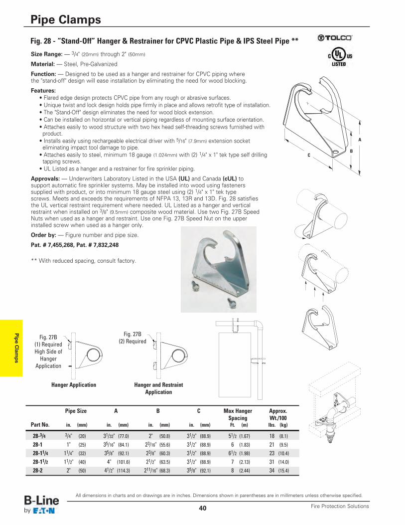
Pipe Clam
ps
All dimensions in charts and on drawings are in inches. Dimensions shown in parentheses are in millimeters unless otherwise specified.
Pipe Clamps
Fire Protection Solutions40
Fig. 28 - “Stand-Off” Hanger & Restrainer for CPVC Plastic Pipe & IPS Steel Pipe **
Size Range: — 3/4" (20mm) through 2" (50mm)
Material: — Steel, Pre-Galvanized
Function: — Designed to be used as a hanger and restrainer for CPVC piping wherethe "stand-off" design will ease installation by eliminating the need for wood blocking.
Features:• Flared edge design protects CPVC pipe from any rough or abrasive surfaces.• Unique twist and lock design holds pipe firmly in place and allows retrofit type of installation.• The "Stand-Off" design eliminates the need for wood block extension.• Can be installed on horizontal or vertical piping regardless of mounting surface orientation.• Attaches easily to wood structure with two hex head self-threading screws furnished withproduct.
• Installs easily using rechargeable electrical driver with 5/16" (7.9mm) extension socket eliminating impact tool damage to pipe.
• Attaches easily to steel, minimum 18 gauge (1.024mm) with (2) 1/4" x 1" tek type self drillingtapping screws.
• UL Listed as a hanger and a restrainer for fire sprinkler piping.
Approvals: — Underwriters Laboratory Listed in the USA (UL) and Canada (cUL) tosupport automatic fire sprinkler systems. May be installed into wood using fastenerssupplied with product, or into minimum 18 gauge steel using (2) 1/4" x 1" tek typescrews. Meets and exceeds the requirements of NFPA 13, 13R and 13D. Fig. 28 satisfiesthe UL vertical restraint requirement where needed. UL Listed as a hanger and verticalrestraint when installed on 3/8" (9.5mm) composite wood material. Use two Fig. 27B SpeedNuts when used as a hanger and restraint. Use one Fig. 27B Speed Nut on the upperinstalled screw when used as a hanger only.
Order by: — Figure number and pipe size.
Pat. # 7,455,268, Pat. # 7,832,248
** With reduced spacing, consult factory.
C
A
B
Pipe Size A B C Max Hanger Approx.Spacing Wt./100
Part No. in. (mm) in. (mm) in. (mm) in. (mm) Ft. (m) lbs. (kg)
28-3/4 3/4" (20) 31/32" (77.0) 2" (50.8) 31/2" (88.9) 51/2 (1.67) 18 (8.1)
28-1 1" (25) 35/16" (84.1) 23/16" (55.6) 31/2" (88.9) 6 (1.83) 21 (9.5)
28-11/4 11/4" (32) 35/8" (92.1) 23/8" (60.3) 31/2" (88.9) 61/2 (1.98) 23 (10.4)28-11/2 11/2" (40) 4" (101.6) 21/2" (63.5) 31/2" (88.9) 7 (2.13) 31 (14.0)28-2 2" (50) 41/2" (114.3) 211/16" (68.3) 35/8" (92.1) 8 (2.44) 34 (15.4)
Hanger Application Hanger and RestraintApplication
Fig. 27B(2) Required
Fig. 27B(1) RequiredHigh Side ofHangerApplication
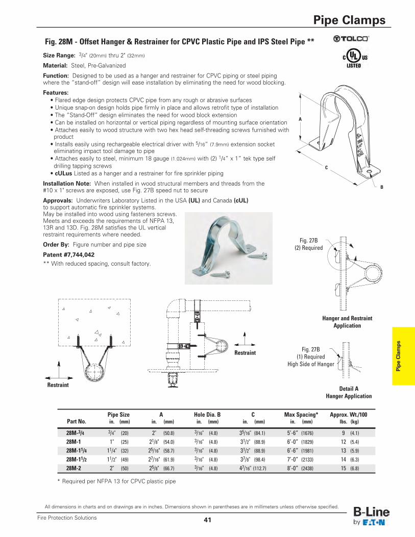
Pipe Clamps
All dimensions in charts and on drawings are in inches. Dimensions shown in parentheses are in millimeters unless otherwise specified.
Pipe Clamps
41Fire Protection Solutions
Fig. 28M - Offset Hanger & Restrainer for CPVC Plastic Pipe and IPS Steel Pipe **
Size Range: 3/4" (20mm) thru 2" (32mm)
Material: Steel, Pre-Galvanized
Function: Designed to be used as a hanger and restrainer for CPVC piping or steel pipingwhere the “stand-off” design will ease installation by eliminating the need for wood blocking.
Features:• Flared edge design protects CPVC pipe from any rough or abrasive surfaces• Unique snap-on design holds pipe firmly in place and allows retrofit type of installation• The “Stand-Off” design eliminates the need for wood block extension• Can be installed on horizontal or vertical piping regardless of mounting surface orientation• Attaches easily to wood structure with two hex head self-threading screws furnished withproduct
• Installs easily using rechargeable electrical driver with 5/16” (7.9mm) extension socketeliminating impact tool damage to pipe
• Attaches easily to steel, minimum 18 gauge (1.024mm) with (2) 1/4” x 1” tek type selfdrilling tapping screws
• cULus Listed as a hanger and a restrainer for fire sprinkler piping
Installation Note: When installed in wood structural members and threads from the#10 x 1" screws are exposed, use Fig. 27B speed nut to secure
Approvals: Underwriters Laboratory Listed in the USA (UL) and Canada (cUL)to support automatic fire sprinkler systems.May be installed into wood using fasteners screws.Meets and exceeds the requirements of NFPA 13,13R and 13D. Fig. 28M satisfies the UL verticalrestraint requirements where needed.
Order By: Figure number and pipe size
Patent #7,744,042** With reduced spacing, consult factory.
C
A
B
Pipe Size A Hole Dia. B C Max Spacing* Approx. Wt./100Part No. in. (mm) in. (mm) in. (mm) in. (mm) in. (mm) lbs. (kg)
28M-3/4 3/4" (20) 2" (50.8) 3/16" (4.8) 35/16" (84.1) 5’-6” (1676) 9 (4.1)
28M-1 1" (25) 21/8" (54.0) 3/16" (4.8) 31/2" (88.9) 6’-0” (1829) 12 (5.4)28M-11/4 11/4" (32) 25/16" (58.7) 3/16" (4.8) 31/2" (88.9) 6’-6” (1981) 13 (5.9)28M-11/2 11/2" (49) 27/16" (61.9) 3/16" (4.8) 37/8" (98.4) 7’-0” (2133) 14 (6.3)28M-2 2" (50) 25/8" (66.7) 3/16" (4.8) 47/16" (112.7) 8’-0” (2438) 15 (6.8)
* Required per NFPA 13 for CPVC plastic pipe
Hanger and RestraintApplication
Restraint
Restraint
Detail AHanger Application
Fig. 27B(2) Required
Fig. 27B(1) Required
High Side of Hanger
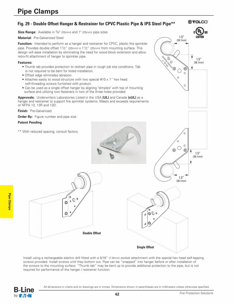
Pipe Clam
ps
All dimensions in charts and on drawings are in inches. Dimensions shown in parentheses are in millimeters unless otherwise specified.
Pipe Clamps
Fire Protection Solutions42
Fig. 29 - Double Offset Hanger & Restrainer for CPVC Plastic Pipe & IPS Steel Pipe**
Size Range: Available in 3/4" (20mm) and 1" (25mm) pipe sizes
Material: Pre-Galvanized Steel
Function: Intended to perform as a hanger and restrainer for CPVC, plastic fire sprinklerpipe. Provides double offset 11/2” (20mm) x 11/2” (20mm) from mounting surface. Thisdesign will ease installation by eliminating the need for wood block extension and allowretro-fit attachment of hanger to sprinkler pipe.
Features:• Thumb tab provides protection to restrain pipe in rough job site conditions. Tabis not required to be bent for listed installation.
• Offset edge eliminates abrasion.• Attaches easily to wood structure with two special #10 x 1” hex head self-threading screws furnished with product.
• Can be used as a single offset hanger by aligning "dimples" with top of mountingsurface and utilizing two fasteners in two of the three holes provided.
Approvals: Underwriters Laboratories Listed in the USA (UL) and Canada (cUL) as ahanger and restrainer to support fire sprinkler systems. Meets and exceeds requirementsof NFPA 13, 13R and 13D.
Finish: Pre-Galvanized
Order By: Figure number and pipe size.
Patent Pending
** With reduced spacing, consult factory.
Install using a rechargeable electric drill fitted with a 5/16” (7.9mm) socket attachment with the special hex head self-tappingscrews provided. Install screws until they bottom out. Pipe can be “snapped” into hanger before or after installation ofthe screws to the mounting surface. “Thumb tab” may be bent up to provide additional protection to the pipe, but is notrequired for performance of the hanger / restrainer function.
Double Offset
Single Offset
1.5”(38.1mm)
1.5”(38.1mm)
1.5”(38.1mm)
1.5”(38.1mm)
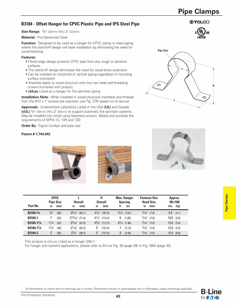
Pipe Clamps
All dimensions in charts and on drawings are in inches. Dimensions shown in parentheses are in millimeters unless otherwise specified.
Pipe Clamps
43Fire Protection Solutions
B3184 - Offset Hanger for CPVC Plastic Pipe and IPS Steel Pipe
Size Range: 3/4" (20mm) thru 2" (32mm)
Material: Pre-Galvanized Steel
Function: Designed to be used as a hanger for CPVC piping or steel pipingwhere the stand-off design will ease installation by eliminating the need forwood blocking.
Features:• Flared edge design protects CPVC pipe from any rough or abrasivesurfaces
• The stand-off design eliminates the need for wood block extension• Can be installed on horizontal or vertical piping regardless of mountingsurface orientation
• Attaches easily to wood structure with two hex head self-threading screws furnished with product
• cULus Listed as a hanger for fire sprinkler piping
Installation Note: When installed in wood structural members and threadsfrom the #10 x 1" screws are exposed, use Fig. 27B speed nut to secure
Approvals: Underwriters Laboratory Listed in the USA (UL) and Canada(cUL) 3/4" (20mm) thru 2" (50mm) to support automatic fire sprinkler systems.May be installed into wood using fasteners screws. Meets and exceeds therequirements of NFPA 13, 13R and 13D.
Order By: Figure number and pipe size
Patent # 7,744,042
H
L
Pipe Size
CPVC L H Max. Hanger Fastener Hex Approx.Pipe Size Overall Overall Spacing Head Size Wt./100
Part No. in. (mm) in. (mm) in. (mm) ft. (m) in. (mm) Lbs. (kg)
B3184-3/4 3/4" (20) 29/16" (65.1) 41/4" (107.9) 51/2 (1.67) 5/16" (7.9) 9.0 (4.1)
B3184-1 1" (25) 213/16" (71.4) 41/2" (114.3) 6 (1,83) 5/16" (7.9) 10.0 (4.5)B3184-11/4 11/4" (32) 33/16" (81.0) 45/8" (117.5) 61/2 (1.98) 5/16" (7.9) 12.0 (5.4)B3184-11/2 11/2" (40) 37/16" (87.3) 5" (127.0) 7 (2.13) 5/16" (7.9) 12.0 (5.4)B3184-2 2" (50) 37/8" (98.4) 5" (127.0) 8 (2.44) 5/16" (7.9) 15.0 (6.8)
This product is cULus Listed as a hanger ONLY.For hanger and restraint applications, please refer to B-Line Fig. 28 (page 39) or Fig. 28M (page 40).
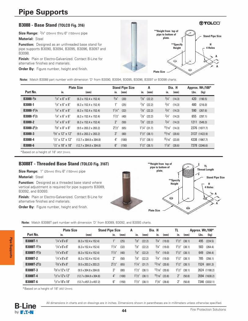
Pipe Supports
Size Range: 3/4" (20mm) thru 6" (150mm) pipe
Material: Steel
Function: Designed as an unthreaded base stand forpipe supports B3090, B3094, B3095, B3096, B3097 andB3098.
Finish: Plain or Electro-Galvanized. Contact B-Line foralternative finishes and materials.
Order By: Figure number, height and finish.
B3088 - Base Stand (TOLCO Fig. 316)
Size Range: 1" (25mm) thru 6" (150mm) pipe
Material: Steel
Function: Designed as a threaded base stand wherevertical adjustment is required for pipe supports B3089,B3092, and B3093.
Finish: Plain or Electro-Galvanized. Contact B-Line foralternative finishes and materials.
Order By: Figure number, height and finish.
B3088T - Threaded Base Stand (TOLCO Fig. 316T)
*Based on a height of 18" (457.2mm).
*Based on a height of 18" (457.2mm).
Note: Match B3088T part number with dimension 'D' from B3089, B3092, and B3093 charts.
H4 Holes
**SpecifyHeight
Plate Size
Stand Pipe Size
A
A
H4 Holes
Plate Size
Stand Pipe Size
TLThread Length
A
A
Plate Size Stand Pipe Size A Dia. H TL Approx. Wt./100*Part No. in. (mm) in. (mm) in. (mm) in. (mm) in. (mm) Lbs. (kg)
B3088T-1 1/4"x 6"x 6" (6.3 x 152.4 x 152.4) 1" (25) 7/8" (22.2) 3/4" (19.0) 11/2" (38.1) 495 (224.5)
B3088T-11/4 1/4"x 6"x 6" (6.3 x 152.4 x 152.4) 11/4" (32) 7/8" (22.2) 3/4" (19.0) 11/2" (38.1) 583 (264.4)
B3088T-11/2 1/4"x 6"x 6" (6.3 x 152.4 x 152.4) 11/2" (40) 7/8" (22.2) 3/4" (19.0) 11/2" (38.1) 649 (294.4)
B3088T-2 1/4"x 6"x 6" (6.3 x 152.4 x 152.4) 2" (50) 7/8" (22.2) 3/4" (19.0) 11/2" (38.1) 785 (356.1)
B3088T-21/2 3/8"x 8"x 8" (9.5 x 203.2 x 203.2) 21/2" (65) 11/4" (31.7) 13/16" (20.6) 11/2" (38.1) 1524 (691.3)
B3088T-3 3/8"x 12"x 12" (9.5 x 304.8 x 304.8) 3" (80) 11/2" (38.1) 13/16" (20.6) 11/2" (38.1) 2624 (1190.2)
B3088T-4 1/2"x 12"x 12" (12.7 x 304.8 x 304.8) 4" (100) 11/2" (38.1) 15/16" (23.8) 2" (50.8) 3594 (1630.2)
B3088T-6 1/2"x 18"x 18" (12.7 x 457.2 x 457.2) 6" (150) 11/2" (38.1) 11/8" (28.6) 2" (50.8) 7346 (3332.1)
Plate Size Stand Pipe Size A Dia. H Approx. Wt./100*Part No. in. (mm) in. (mm) in. (mm) in. (mm) Lbs. (kg)
B3088-3/4 1/4" x 6" x 6" (6.3 x 152.4 x 152.4) 3/4" (20) 7/8" (22.2) 3/4" (14.3) 420 (190.5)
B3088-1 1/4" x 6" x 6" (6.3 x 152.4 x 152.4) 1" (25) 7/8" (22.2) 3/4" (14.3) 480 (216.0)
B3088-11/4 1/4" x 6" x 6" (6.3 x 152.4 x 152.4) 11/4” (32) 7/8" (22.2) 3/4" (14.3) 590 (267.6)
B3088-11/2 1/4" x 6" x 6" (6.3 x 152.4 x 152.4) 11/2" (40) 7/8" (22.2) 3/4" (14.3) 655 (297.1)
B3088-2 1/4" x 6" x 6" (6.3 x 152.4 x 152.4) 2" (50) 7/8" (22.2) 3/4" (14.3) 1211 (549.3)
B3088-21/2 3/8" x 8" x 8" (9.5 x 203.2 x 203.2) 21/2" (65) 11/4" (31.7) 13/16" (14.3) 2376 (1077.7)
B3088-3 3/8" x 12" x 12" (9.5 x 203.2 x 203.2) 3" (80) 11/2" (38.1) 13/16" (20.6) 3137 (1422.9)
B3088-4 1/2" x 12" x 12" (12.7 x 304.8 x 304.8) 4" (100) 11/2" (38.1) 15/16" (23.8) 4338 (1967.7)
B3088-6 1/2" x 18" x 18" (12.7 x 304.8 x 304.8) 6" (150) 11/2" (38.1) 11/8" (28.6) 7378 (3346.6)
**Height from top ofpipe to bottom of
plate.
**SpecifyHeight
**Height from top ofpipe to bottom of
plate.
Note: Match B3088 part number with dimension 'D' from B3090, B3094, B3095, B3096, B3097 or B3098 charts.
All dimensions in charts and on drawings are in inches. Dimensions shown in parentheses are in millimeters unless otherwise specified.
Pipe Supports
Fire Protection Solutions44
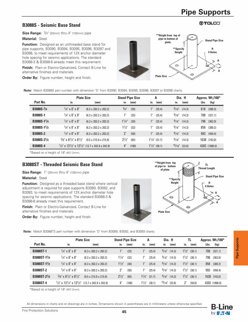
Pipe Sup
ports
B3088S - Seismic Base Stand
B3088ST - Threaded Seismic Base Stand
*Based on a height of 18" (457.2mm).
*Based on a height of 18" (457.2mm).
Plate Size Stand Pipe Size A Dia. H TL Approx. Wt./100*Part No. in. (mm) in. (mm) in. (mm) in. (mm) in. (mm) Lbs. (kg)
B3088ST-1 1/4" x 8" x 8" (6.3 x 203.2 x 203.2) 1" (25) 1" (25.4) 9/16" (14.3) 11/2" (38.1) 708 (321.1)
B3088ST-11/4 1/4" x 8" x 8" (6.3 x 203.2 x 203.2) 11/4" (32) 1" (25.4) 9/16" (14.3) 11/2" (38.1) 798 (362.0)
B3088ST-11/2 1/4" x 8" x 8" (6.3 x 203.2 x 203.2) 11/2" (40) 1" (25.4) 9/16" (14.3) 11/2" (38.1) 858 (389.2)
B3088ST-2 1/4" x 8" x 8" (6.3 x 203.2 x 203.2) 2" (50) 1" (25.4) 9/16" (14.3) 11/2" (38.1) 993 (450.4)
B3088ST-21/2 3/8" x 81/2" x 81/2" (9.5 x 215.9 x 215.9) 21/2" (65) 11/4" (31.7) 9/16" (14.3) 11/2" (38.1) 1638 (743.0)
B3088ST-4 1/2" x 131/2" x 131/2" (12.7 x 342.9 x 342.9) 4" (100) 11/2" (38.1) 15/16" (23.8) 2" (50.8) 4202 (1906.0)
Plate Size Stand Pipe Size A Dia. H Approx. Wt./100*Part No. in. (mm) in. (mm) in. (mm) in. (mm) Lbs. (kg)
B3088S-3/4 1/4" x 8" x 8" (6.3 x 203.2 x 203.2) 3/4" (20) 1" (25.4) 9/16" (14.3) 618 (280.3)
B3088S-1 1/4" x 8" x 8" (6.3 x 203.2 x 203.2) 1" (25) 1" (25.4) 9/16" (14.3) 708 (321.1)
B3088S-11/4 1/4" x 8" x 8" (6.3 x 203.2 x 203.2) 11/4” (20) 1" (25.4) 9/16" (14.3) 798 (362.0)
B3088S-11/2 1/4" x 8" x 8" (6.3 x 203.2 x 203.2) 11/2" (32) 1" (25.4) 9/16" (14.3) 858 (389.2)
B3088S-2 1/4" x 8" x 8" (6.3 x 203.2 x 203.2) 2" (50) 1" (25.4) 9/16" (14.3) 993 (450.4)
B3088S-21/2 3/8" x 81/2" x 81/2" (9.5 x 215.9 x 215.9) 21/2" (65) 11/4" (31.7) 9/16" (14.3) 1638 (743.0)
B3088S-4 1/2" x 131/2" x 131/2" (12.7 x 342.9 x 342.9) 4" (100) 11/2" (38.1) 15/16" (23.8) 4202 (1906.0)
Note: Match B3088S part number with dimension 'D' from B3090, B3094, B3095, B3096, B3097 or B3098 charts.
Note: Match B3088TS part number with dimension 'D' from B3089, B3092, and B3093 charts.
H4 Holes
**SpecifyHeight
Plate Size
Stand Pipe Size
A
A
**Height from top ofpipe to bottom of
plate.
Size Range: 3/4" (20mm) thru 4" (100mm) pipe
Material: Steel
Function: Designed as an unthreaded base stand forpipe supports, B3090, B3094, B3095, B3096, B3097 andB3098, to meet requirements of 12X anchor diameterhole spacing for seismic applications. The standardB3088-3 & B3088-6 already meet this requirement.
Finish: Plain or Electro-Galvanized. Contact B-Line foralternative finishes and materials.
Order By: Figure number, height and finish.
Size Range: 1" (25mm) thru 4" (100mm) pipe
Material: Steel
Function: Designed as a threaded base stand where verticaladjustment is required for pipe supports B3089, B3092, andB3093, to meet requirements of 12X anchor diameter holespacing for seismic applications. The standard B3088-3 &B3088-6 already meet this requirement.
Finish: Plain or Electro-Galvanized. Contact B-Line foralternative finishes and materials.
Order By: Figure number, height and finish.
H4 Holes
Plate Size
Stand Pipe Size
TLThread Length
A
A
**SpecifyHeight
**Height from topof pipe to bottom
of plate.
All dimensions in charts and on drawings are in inches. Dimensions shown in parentheses are in millimeters unless otherwise specified.
Pipe Supports
45Fire Protection Solutions
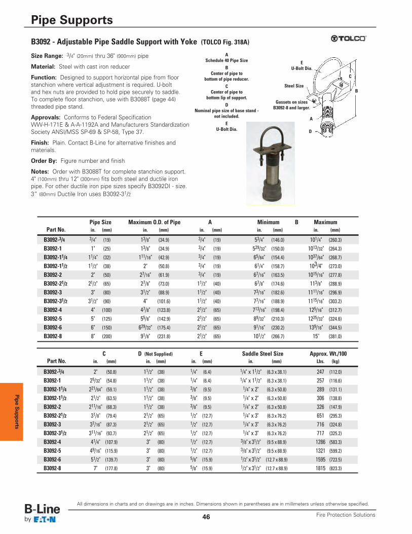
Pipe Supports
Size Range: 3/4" (20mm) thru 36" (900mm) pipe
Material: Steel with cast iron reducer
Function: Designed to support horizontal pipe from floorstanchion where vertical adjustment is required. U-boltand hex nuts are provided to hold pipe securely to saddle.To complete floor stanchion, use with B3088T (page 44)threaded pipe stand.
Approvals: Conforms to Federal SpecificationWW-H-171E & A-A-1192A and Manufacturers StandardizationSociety ANSI/MSS SP-69 & SP-58, Type 37.
Finish: Plain. Contact B-Line for alternative finishes andmaterials.
Order By: Figure number and finish
Notes: Order with B3088T for complete stanchion support.4" (100mm) thru 12" (300mm) fits both steel and ductile ironpipe. For other ductile iron pipe sizes specify B3092DI - size.3” (80mm) Ductile Iron uses B3092-31/2
EU-Bolt Dia.
Steel Size
Gussets on sizes B3092-8 and larger.
ASchedule 40 Pipe Size
BCenter of pipe to
bottom of pipe reducer.
CCenter of pipe to
bottom lip of support.
DNominal pipe size of base stand -
not included.
EU-Bolt Dia.
A
D
C
B
Pipe Size Maximum O.D. of Pipe A Minimum B MaximumPart No. in. (mm) in. (mm) in. (mm) in. (mm) in. (mm)
B3092-3/4 3/4" (19) 13/8" (34.9) 3/4" (19) 53/4" (146.0) 101/4" (260.3)
B3092-1 1" (25) 13/8" (34.9) 3/4" (19) 529/32" (150.0) 1013/32" (264.3)B3092-11/4 11/4" (32) 111/16" (42.9) 3/4" (19) 65/64" (154.4) 1037/64" (268.7)B3092-11/2 11/2" (38) 2" (50.8) 3/4" (19) 61/4" (158.7) 103/4" (273.0)
B3092-2 2" (50) 27/16" (61.9) 3/4" (19) 67/16" (163.5) 1015/16" (277.8)B3092-21/2 21/2" (65) 27/8" (73.0) 11/2" (40) 67/8" (174.6) 113/8" (288.9)
B3092-3 3" (80) 31/2" (88.9) 11/2" (40) 73/16" (182.6) 1111/16" (296.9)B3092-31/2 31/2" (90) 4" (101.6) 11/2" (40) 77/16" (188.9) 1115/16" (303.2)B3092-4 4" (100) 47/8" (123.8) 21/2" (65) 713/16" (198.4) 125/16" (312.7)
B3092-5 5" (125) 55/8" (142.9) 21/2" (65) 89/32" (210.3) 1225/32" (324.6)B3092-6 6" (150) 629/32" (175.4) 21/2" (65) 91/16" (230.2) 139/16" (344.5)
B3092-8 8" (200) 91/8" (231.8) 21/2" (65) 101/2" (266.7) 15" (381.0)
B3092 - Adjustable Pipe Saddle Support with Yoke (TOLCO Fig. 318A)
C D (Not Supplied) E Saddle Steel Size Approx. Wt./100Part No. in. (mm) in. (mm) in. (mm) in. (mm) Lbs. (kg)
B3092-3/4 2" (50.8) 11/2" (38) 1/4" (6.4) 1/4" x 11/2" (6.3 x 38.1) 247 (112.0)
B3092-1 25/32" (54.8) 11/2" (38) 1/4" (6.4) 1/4" x 11/2" (6.3 x 38.1) 257 (116.6)
B3092-11/4 221/64" (59.1) 11/2" (38) 3/8" (9.5) 1/4" x 2" (6.3 x 50.8) 289 (131.1)
B3092-11/2 21/2" (63.5) 11/2" (38) 3/8" (9.5) 1/4" x 2" (6.3 x 50.8) 306 (138.8)
B3092-2 211/16" (68.3) 11/2" (38) 3/8" (9.5) 1/4" x 2" (6.3 x 50.8) 326 (147.9)
B3092-21/2 31/8" (79.4) 21/2" (65) 1/2" (12.7) 1/4" x 3" (6.3 x 76.2) 651 (295.3)
B3092-3 37/16" (87.3) 21/2" (65) 1/2" (12.7) 1/4" x 3" (6.3 x 76.2) 716 (324.8)
B3092-31/2 311/16" (93.7) 21/2" (65) 1/2" (12.7) 1/4" x 3" (6.3 x 76.2) 717 (325.2)
B3092-4 41/4" (107.9) 3" (80) 1/2" (12.7) 3/8" x 31/2" (9.5 x 88.9) 1286 (583.3)B3092-5 49/16" (115.9) 3" (80) 1/2" (12.7) 3/8" x 31/2" (9.5 x 88.9) 1321 (599.2)B3092-6 51/2" (139.7) 3" (80) 5/8" (15.9) 1/2" x 31/2" (12.7 x 88.9) 1595 (723.5)B3092-8 7" (177.8) 3" (80) 5/8" (15.9) 1/2" x 31/2" (12.7 x 88.9) 1815 (823.3)
All dimensions in charts and on drawings are in inches. Dimensions shown in parentheses are in millimeters unless otherwise specified.
Pipe Supports
Fire Protection Solutions46
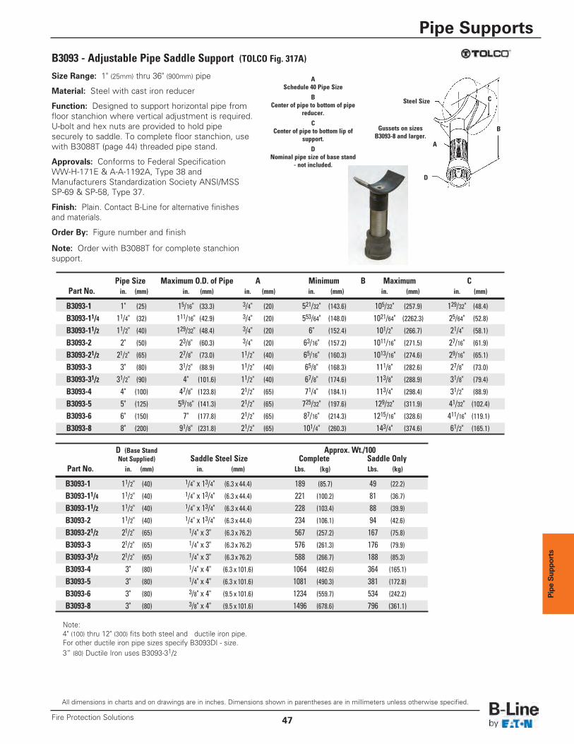
Pipe Sup
ports
Size Range: 1" (25mm) thru 36" (900mm) pipe
Material: Steel with cast iron reducer
Function: Designed to support horizontal pipe fromfloor stanchion where vertical adjustment is required.U-bolt and hex nuts are provided to hold pipesecurely to saddle. To complete floor stanchion, usewith B3088T (page 44) threaded pipe stand.
Approvals: Conforms to Federal SpecificationWW-H-171E & A-A-1192A, Type 38 andManufacturers Standardization Society ANSI/MSSSP-69 & SP-58, Type 37.
Finish: Plain. Contact B-Line for alternative finishesand materials.
Order By: Figure number and finish
Note: Order with B3088T for complete stanchionsupport.
B3093 - Adjustable Pipe Saddle Support (TOLCO Fig. 317A)
Steel Size
Gussets on sizes B3093-8 and larger.
ASchedule 40 Pipe Size
BCenter of pipe to bottom of pipe
reducer.
CCenter of pipe to bottom lip of
support.
DNominal pipe size of base stand
- not included.
A
D
C
B
Pipe Size Maximum O.D. of Pipe A Minimum B Maximum CPart No. in. (mm) in. (mm) in. (mm) in. (mm) in. (mm) in. (mm)
B3093-1 1" (25) 15/16" (33.3) 3/4" (20) 521/32" (143.6) 105/32" (257.9) 129/32" (48.4)B3093-11/4 11/4" (32) 111/16" (42.9) 3/4" (20) 553/64" (148.0) 1021/64" (2262.3) 25/64" (52.8)
B3093-11/2 11/2" (40) 129/32" (48.4) 3/4" (20) 6" (152.4) 101/2" (266.7) 21/4" (58.1)
B3093-2 2" (50) 23/8" (60.3) 3/4" (20) 63/16" (157.2) 1011/16" (271.5) 27/16" (61.9)
B3093-21/2 21/2" (65) 27/8" (73.0) 11/2" (40) 65/16" (160.3) 1013/16" (274.6) 29/16" (65.1)
B3093-3 3" (80) 31/2" (88.9) 11/2" (40) 65/8" (168.3) 111/8" (282.6) 27/8" (73.0)
B3093-31/2 31/2" (90) 4" (101.6) 11/2" (40) 67/8" (174.6) 113/8" (288.9) 31/8" (79.4)
B3093-4 4" (100) 47/8" (123.8) 21/2" (65) 71/4" (184.1) 113/4" (298.4) 31/2" (88.9)
B3093-5 5" (125) 59/16" (141.3) 21/2" (65) 725/32" (197.6) 129/32" (311.9) 41/32" (102.4)B3093-6 6" (150) 7" (177.8) 21/2" (65) 87/16" (214.3) 1215/16" (328.6) 411/16" (119.1)B3093-8 8" (200) 91/8" (231.8) 21/2" (65) 101/4" (260.3) 143/4" (374.6) 61/2" (165.1)
Note:4" (100) thru 12" (300) fits both steel and ductile iron pipe. For other ductile iron pipe sizes specify B3093DI - size.3” (80) Ductile Iron uses B3093-31/2
D (Base Stand Approx. Wt./100Not Supplied) Saddle Steel Size Complete Saddle Only
Part No. in. (mm) in. (mm) Lbs. (kg) Lbs. (kg)
B3093-1 11/2" (40) 1/4" x 13/4" (6.3 x 44.4) 189 (85.7) 49 (22.2)
B3093-11/4 11/2" (40) 1/4" x 13/4" (6.3 x 44.4) 221 (100.2) 81 (36.7)
B3093-11/2 11/2" (40) 1/4" x 13/4" (6.3 x 44.4) 228 (103.4) 88 (39.9)
B3093-2 11/2" (40) 1/4" x 13/4" (6.3 x 44.4) 234 (106.1) 94 (42.6)
B3093-21/2 21/2" (65) 1/4" x 3" (6.3 x 76.2) 567 (257.2) 167 (75.8)
B3093-3 21/2" (65) 1/4" x 3" (6.3 x 76.2) 576 (261.3) 176 (79.9)
B3093-31/2 21/2" (65) 1/4" x 3" (6.3 x 76.2) 588 (266.7) 188 (85.3)
B3093-4 3" (80) 1/4" x 4" (6.3 x 101.6) 1064 (482.6) 364 (165.1)
B3093-5 3" (80) 1/4" x 4" (6.3 x 101.6) 1081 (490.3) 381 (172.8)
B3093-6 3" (80) 3/8" x 4" (9.5 x 101.6) 1234 (559.7) 534 (242.2)
B3093-8 3" (80) 3/8" x 4" (9.5 x 101.6) 1496 (678.6) 796 (361.1)
All dimensions in charts and on drawings are in inches. Dimensions shown in parentheses are in millimeters unless otherwise specified.
Pipe Supports
47Fire Protection Solutions
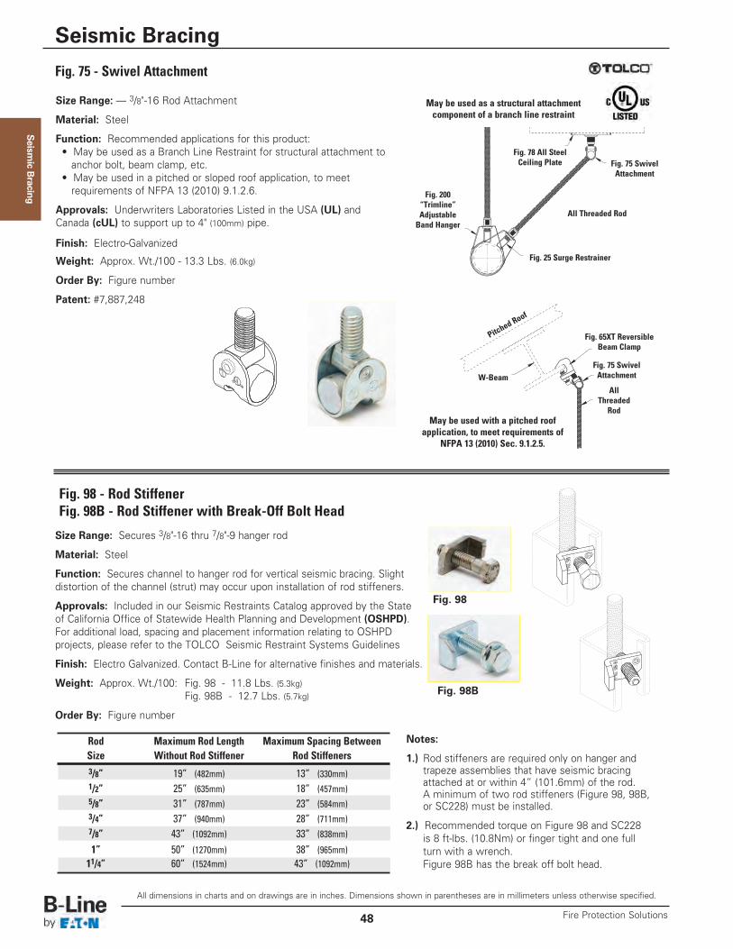
Seism
ic Bracing
All dimensions in charts and on drawings are in inches. Dimensions shown in parentheses are in millimeters unless otherwise specified.
Seismic Bracing
Fire Protection Solutions48
Size Range: — 3/8"-16 Rod Attachment
Material: Steel
Function: Recommended applications for this product: • May be used as a Branch Line Restraint for structural attachment toanchor bolt, beam clamp, etc.
• May be used in a pitched or sloped roof application, to meet requirements of NFPA 13 (2010) 9.1.2.6.
Approvals: Underwriters Laboratories Listed in the USA (UL) and Canada (cUL) to support up to 4" (100mm) pipe.
Finish: Electro-Galvanized
Weight: Approx. Wt./100 - 13.3 Lbs. (6.0kg)
Order By: Figure number
Patent: #7,887,248
Fig. 75 - Swivel Attachment
Fig. 78 All SteelCeiling Plate Fig. 75 Swivel
Attachment
Fig. 75 SwivelAttachment
All Threaded Rod
AllThreaded
Rod
W-Beam
Pitched
Roof
Fig. 25 Surge Restrainer
Fig. 200“Trimline”AdjustableBand Hanger
May be used as a structural attachmentcomponent of a branch line restraint
May be used with a pitched roofapplication, to meet requirements of
NFPA 13 (2010) Sec. 9.1.2.5.
Fig. 65XT ReversibleBeam Clamp
Fig. 98 - Rod StiffenerFig. 98B - Rod Stiffener with Break-Off Bolt Head
Size Range: Secures 3/8"-16 thru 7/8"-9 hanger rod
Material: Steel
Function: Secures channel to hanger rod for vertical seismic bracing. Slightdistortion of the channel (strut) may occur upon installation of rod stiffeners.
Approvals: Included in our Seismic Restraints Catalog approved by the Stateof California Office of Statewide Health Planning and Development (OSHPD).For additional load, spacing and placement information relating to OSHPDprojects, please refer to the TOLCO Seismic Restraint Systems Guidelines
Finish: Electro Galvanized. Contact B-Line for alternative finishes and materials.
Weight: Approx. Wt./100: Fig. 98 - 11.8 Lbs. (5.3kg)Fig. 98B - 12.7 Lbs. (5.7kg)
Order By: Figure number
Fig. 98B
Fig. 98
Notes:
1.) Rod stiffeners are required only on hanger andtrapeze assemblies that have seismic bracingattached at or within 4” (101.6mm) of the rod.A minimum of two rod stiffeners (Figure 98, 98B,or SC228) must be installed.
2.) Recommended torque on Figure 98 and SC228 is 8 ft-lbs. (10.8Nm) or finger tight and one full turn with a wrench.Figure 98B has the break off bolt head.
Rod Maximum Rod Length Maximum Spacing BetweenSize Without Rod Stiffener Rod Stiffeners3/8” 19” (482mm) 13” (330mm)1/2” 25” (635mm) 18” (457mm)5/8” 31” (787mm) 23” (584mm)3/4” 37” (940mm) 28” (711mm)7/8” 43” (1092mm) 33” (838mm)1” 50” (1270mm) 38” (965mm)11/4” 60” (1524mm) 43” (1092mm)
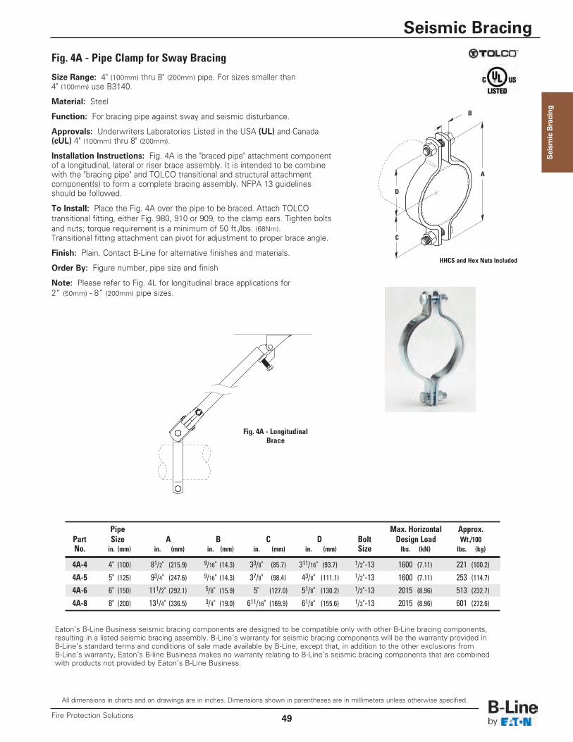
All dimensions in charts and on drawings are in inches. Dimensions shown in parentheses are in millimeters unless otherwise specified.
Seismic Bracing
49Fire Protection Solutions
Seism
ic Bracing
Eaton’s B-Line Business seismic bracing components are designed to be compatible only with other B-Line bracing components, resulting in a listed seismic bracing assembly. B-Line’s warranty for seismic bracing components will be the warranty provided in B-Line’s standard terms and conditions of sale made available by B-Line, except that, in addition to the other exclusions from B-Line’s warranty, Eaton’s B-line Business makes no warranty relating to B-Line’s seismic bracing components that are combined with products not provided by Eaton’s B-Line Business.
Fig. 4A - Pipe Clamp for Sway Bracing
Size Range: 4" (100mm) thru 8" (200mm) pipe. For sizes smaller than4" (100mm) use B3140.
Material: Steel
Function: For bracing pipe against sway and seismic disturbance.
Approvals: Underwriters Laboratories Listed in the USA (UL) and Canada(cUL) 4" (100mm) thru 8" (200mm).
Installation Instructions: Fig. 4A is the "braced pipe" attachment componentof a longitudinal, lateral or riser brace assembly. It is intended to be combinewith the "bracing pipe" and TOLCO transitional and structural attachmentcomponent(s) to form a complete bracing assembly. NFPA 13 guidelinesshould be followed.
To Install: Place the Fig. 4A over the pipe to be braced. Attach TOLCOtransitional fitting, either Fig. 980, 910 or 909, to the clamp ears. Tighten boltsand nuts; torque requirement is a minimum of 50 ft./lbs. (68Nm).Transitional fitting attachment can pivot for adjustment to proper brace angle.
Finish: Plain. Contact B-Line for alternative finishes and materials.
Order By: Figure number, pipe size and finish
Note: Please refer to Fig. 4L for longitudinal brace applications for2” (50mm) - 8” (200mm) pipe sizes.
C
D
A
B
Pipe Max. Horizontal Approx.Part Size A B C D Bolt Design Load Wt./100No. in. (mm) in. (mm) in. (mm) in. (mm) in. (mm) Size lbs. (kN) lbs. (kg)
4A-4 4" (100) 81/2" (215.9) 9/16" (14.3) 33/8" (85.7) 311/16" (93.7) 1/2"-13 1600 (7.11) 221 (100.2)
4A-5 5" (125) 93/4" (247.6) 9/16" (14.3) 37/8" (98.4) 43/8" (111.1) 1/2"-13 1600 (7.11) 253 (114.7)
4A-6 6" (150) 111/2" (292.1) 5/8" (15.9) 5" (127.0) 51/8" (130.2) 1/2"-13 2015 (8.96) 513 (232.7)
4A-8 8" (200) 131/4" (336.5) 3/4" (19.0) 611/16" (169.9) 61/8" (155.6) 1/2"-13 2015 (8.96) 601 (272.6)
Fig. 4A - LongitudinalBrace
HHCS and Hex Nuts Included
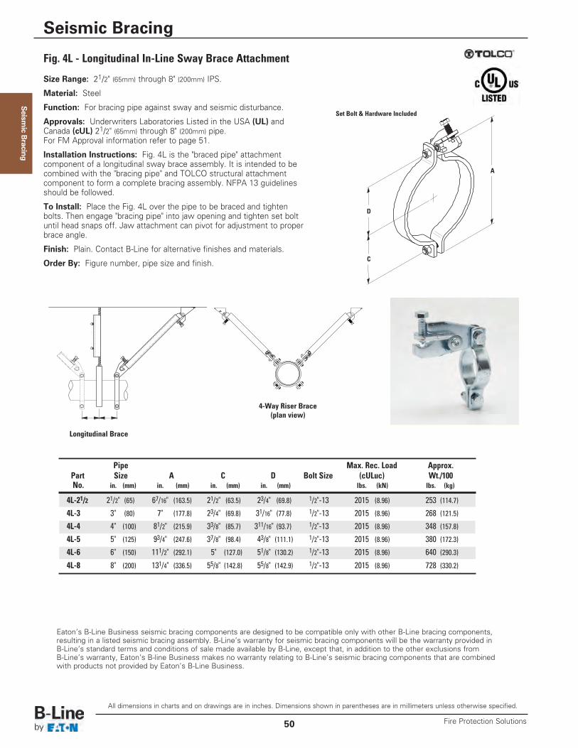
Seism
ic Bracing
Fig. 4L - Longitudinal In-Line Sway Brace Attachment
Size Range: 21/2" (65mm) through 8" (200mm) IPS.
Material: Steel
Function: For bracing pipe against sway and seismic disturbance.
Approvals: Underwriters Laboratories Listed in the USA (UL) andCanada (cUL) 21/2" (65mm) through 8" (200mm) pipe.For FM Approval information refer to page 51.
Installation Instructions: Fig. 4L is the "braced pipe" attachmentcomponent of a longitudinal sway brace assembly. It is intended to becombined with the "bracing pipe" and TOLCO structural attachmentcomponent to form a complete bracing assembly. NFPA 13 guidelinesshould be followed.
To Install: Place the Fig. 4L over the pipe to be braced and tightenbolts. Then engage "bracing pipe" into jaw opening and tighten set boltuntil head snaps off. Jaw attachment can pivot for adjustment to properbrace angle.
Finish: Plain. Contact B-Line for alternative finishes and materials.
Order By: Figure number, pipe size and finish. C
A
D
Pipe Max. Rec. Load Approx.Part Size A C D Bolt Size (cULuc) Wt./100No. in. (mm) in. (mm) in. (mm) in. (mm) lbs. (kN) lbs. (kg)
4L-21/2 21/2" (65) 67/16" (163.5) 21/2" (63.5) 23/4" (69.8) 1/2"-13 2015 (8.96) 253 (114.7)
4L-3 3" (80) 7" (177.8) 23/4" (69.8) 31/16" (77.8) 1/2"-13 2015 (8.96) 268 (121.5)
4L-4 4" (100) 81/2" (215.9) 33/8" (85.7) 311/16" (93.7) 1/2"-13 2015 (8.96) 348 (157.8)
4L-5 5" (125) 93/4" (247.6) 37/8" (98.4) 43/8" (111.1) 1/2"-13 2015 (8.96) 380 (172.3)
4L-6 6" (150) 111/2" (292.1) 5" (127.0) 51/8" (130.2) 1/2"-13 2015 (8.96) 640 (290.3)
4L-8 8" (200) 131/4" (336.5) 55/8" (142.8) 55/8" (142.9) 1/2"-13 2015 (8.96) 728 (330.2)
Eaton’s B-Line Business seismic bracing components are designed to be compatible only with other B-Line bracing components, resulting in a listed seismic bracing assembly. B-Line’s warranty for seismic bracing components will be the warranty provided in B-Line’s standard terms and conditions of sale made available by B-Line, except that, in addition to the other exclusions from B-Line’s warranty, Eaton’s B-line Business makes no warranty relating to B-Line’s seismic bracing components that are combined with products not provided by Eaton’s B-Line Business.
Longitudinal Brace
4-Way Riser Brace(plan view)
Set Bolt & Hardware Included
All dimensions in charts and on drawings are in inches. Dimensions shown in parentheses are in millimeters unless otherwise specified.
Seismic Bracing
Fire Protection Solutions50
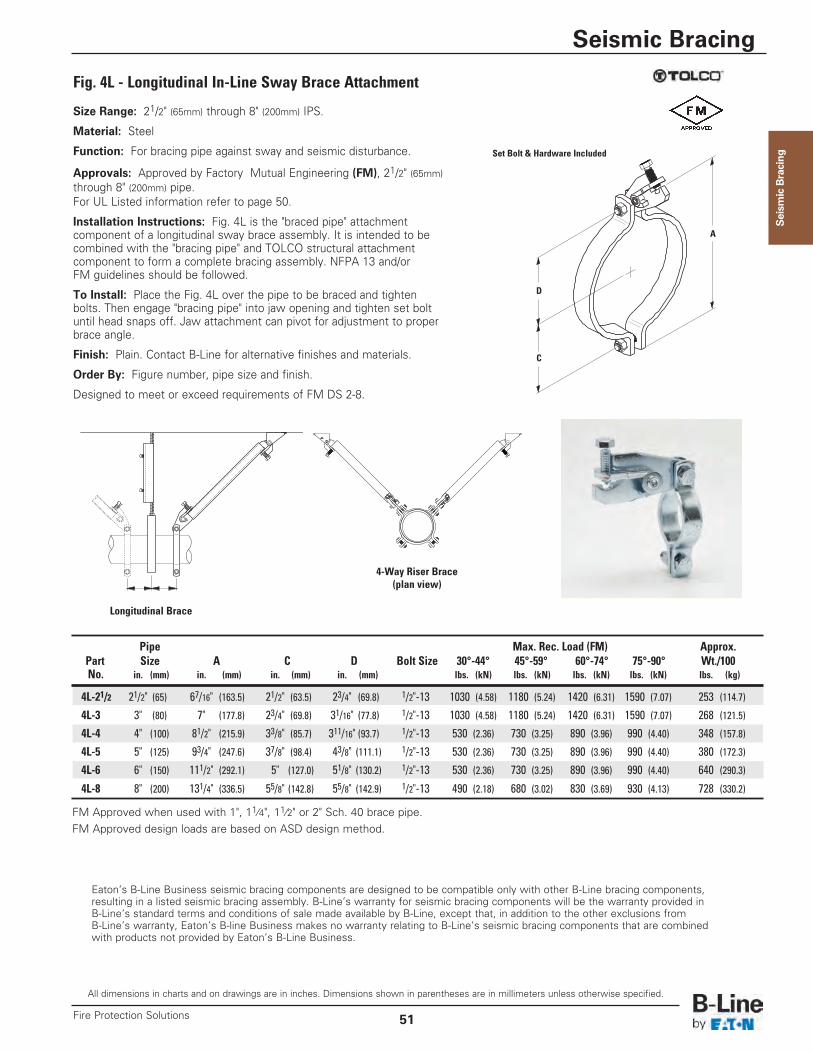
Seism
ic Bracing
Fig. 4L - Longitudinal In-Line Sway Brace Attachment
Size Range: 21/2" (65mm) through 8" (200mm) IPS.
Material: Steel
Function: For bracing pipe against sway and seismic disturbance.
Approvals: Approved by Factory Mutual Engineering (FM), 21/2" (65mm)through 8" (200mm) pipe.For UL Listed information refer to page 50.
Installation Instructions: Fig. 4L is the "braced pipe" attachmentcomponent of a longitudinal sway brace assembly. It is intended to becombined with the "bracing pipe" and TOLCO structural attachmentcomponent to form a complete bracing assembly. NFPA 13 and/orFM guidelines should be followed.
To Install: Place the Fig. 4L over the pipe to be braced and tightenbolts. Then engage "bracing pipe" into jaw opening and tighten set boltuntil head snaps off. Jaw attachment can pivot for adjustment to properbrace angle.
Finish: Plain. Contact B-Line for alternative finishes and materials.
Order By: Figure number, pipe size and finish.
Designed to meet or exceed requirements of FM DS 2-8.
Eaton’s B-Line Business seismic bracing components are designed to be compatible only with other B-Line bracing components, resulting in a listed seismic bracing assembly. B-Line’s warranty for seismic bracing components will be the warranty provided in B-Line’s standard terms and conditions of sale made available by B-Line, except that, in addition to the other exclusions from B-Line’s warranty, Eaton’s B-line Business makes no warranty relating to B-Line’s seismic bracing components that are combined with products not provided by Eaton’s B-Line Business.
FM Approved when used with 1", 11⁄4", 11⁄2" or 2" Sch. 40 brace pipe.FM Approved design loads are based on ASD design method.
Longitudinal Brace
4-Way Riser Brace(plan view)
Pipe Max. Rec. Load (FM) Approx.Part Size A C D Bolt Size 30°-44° 45°-59° 60°-74° 75°-90° Wt./100No. in. (mm) in. (mm) in. (mm) in. (mm) lbs. (kN) lbs. (kN) lbs. (kN) lbs. (kN) lbs. (kg)
4L-21/2 21/2" (65) 67/16" (163.5) 21/2" (63.5) 23/4" (69.8) 1/2"-13 1030 (4.58) 1180 (5.24) 1420 (6.31) 1590 (7.07) 253 (114.7)
4L-3 3" (80) 7" (177.8) 23/4" (69.8) 31/16" (77.8) 1/2"-13 1030 (4.58) 1180 (5.24) 1420 (6.31) 1590 (7.07) 268 (121.5)
4L-4 4" (100) 81/2" (215.9) 33/8" (85.7) 311/16" (93.7) 1/2"-13 530 (2.36) 730 (3.25) 890 (3.96) 990 (4.40) 348 (157.8)
4L-5 5" (125) 93/4" (247.6) 37/8" (98.4) 43/8" (111.1) 1/2"-13 530 (2.36) 730 (3.25) 890 (3.96) 990 (4.40) 380 (172.3)
4L-6 6" (150) 111/2" (292.1) 5" (127.0) 51/8" (130.2) 1/2"-13 530 (2.36) 730 (3.25) 890 (3.96) 990 (4.40) 640 (290.3)
4L-8 8" (200) 131/4" (336.5) 55/8" (142.8) 55/8" (142.9) 1/2"-13 490 (2.18) 680 (3.02) 830 (3.69) 930 (4.13) 728 (330.2)
C
A
D
Set Bolt & Hardware Included
All dimensions in charts and on drawings are in inches. Dimensions shown in parentheses are in millimeters unless otherwise specified.
Seismic Bracing
51Fire Protection Solutions
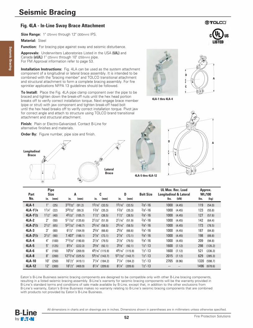
Size Range: 1" (25mm) through 12" (300mm) IPS.
Material: Steel
Function: For bracing pipe against sway and seismic disturbance.
Approvals: Underwriters Laboratories Listed in the USA (UL) andCanada (cUL) 1" (25mm) through 10" (250mm) pipe.For FM Approval information refer to page 53.
Installation Instructions: Fig. 4LA can be used as the system attachmentcomponent of a longitudinal or lateral brace assembly. It is intended to becombined with the "bracing member" and TOLCO transitional attachmentand structural attachment to form a complete bracing assembly. For firesprinkler applications NFPA 13 guidelines should be followed.
To Install: Place the Fig. 4LA pipe clamp component over the pipe to bebraced and tighten down the break-off nuts until the hex head portionbreaks off to verify correct installation torque. Next engage brace member(pipe or strut) with jaw component and tighten break-off head boltuntil the hex head breaks off to verify correct installation torque. Pivot jawfor correct angle and attach to structure using TOLCO brand transitionalattachment and structural attachment.
Finish: Plain or Electro-Galvanized. Contact B-Line foralternative finishes and materials.
Order By: Figure number, pipe size and finish.
Fig. 4LA - In-Line Sway Brace Attachment
Eaton’s B-Line Business seismic bracing components are designed to be compatible only with other B-Line bracing components, resulting in a listed seismic bracing assembly. B-Line’s warranty for seismic bracing components will be the warranty provided in B-Line’s standard terms and conditions of sale made available by B-Line, except that, in addition to the other exclusions from B-Line’s warranty, Eaton’s B-line Business makes no warranty relating to B-Line’s seismic bracing components that are combined with products not provided by Eaton’s B-Line Business.
Pipe UL Max. Rec. Load Approx.Part Size A C D Bolt Size Longitudinal & Lateral Wt./100No. in. (mm) in. (mm) in. (mm) in. (mm) lbs. (kN) lbs. (kg)
4LA-1 1" (25) 319/32" (91.2) 15/16" (33.5) 15/16" (33.5) 3/8"-16 1000 (4.45) 119 (54.0)4LA-11/4 11/4" (32) 329/32" (99.3) 13/8" (35.3) 13/8" (35.3) 3/8"-16 1000 (4.45) 123 (55.8)4LA-11/2 11/2" (40) 45/32" (105.7) 11/2" (38.5) 11/2" (38.5) 3/8"-16 1000 (4.45) 127 (57.6)4LA-2 2" (50) 511/32" (135.6) 21/32" (51.9) 21/16" (51.9) 3/8"-16 1000 (4.45) 142 (64.4)4LA-21/2 21/2" (65) 527/32" (148.7) 25/16" (58.5) 25/16" (58.5) 3/8"-16 1000 (4.45) 173 (78.5)4LA-3 3" (80) 61/2" (164.9) 25/8" (66.6) 25/8" (66.6) 3/8"-16 1000 (4.45) 187 (84.8)4LA-31/2 31/2" (90) 7.407" (188.1) 27/8" (73.1) 27/8" (73.1) 3/8"-16 1000 (4.45) 198 (89.8)4LA-4 4" (100) 713/32" (190.8) 31/8" (79.5) 31/8" (79.5) 3/8"-16 1000 (4.45) 209 (94.8)4LA-5 5" (125) 83/4" (222.3) 35/8" (92.1) 35/8" (92.1) 1/2"-13 1600 (7.12) 298 (135.2)4LA-6 6" (150) 105/8" (269.9) 49/16" (115.9) 49/16" (115.9) 1/2"-13 1600 (7.12) 521 (236.3)4LA-8 8" (200) 1213/16" (325.5) 59/16" (143.7) 521/32" (143.7) 1/2"-13 2015 (7.12) 629 (285.3)4LA-10 10" (250) 161/2" (419.1) 71/4" (184.2) 71/4" (184.2) 1/2"-13 2765 (8.96) 1320 (598.7)4LA-12 12" (300) 181/2" (469.9) 81/4" (209.6) 81/4" (209.6) 1/2"-13 -- -- 1496 (678.6)
4LA-1 thru 4LA-4
4LA-5 thru 4LA-12
LongitudinalBrace
LateralBrace
C
AD
C
AD
Seism
ic Bracing
All dimensions in charts and on drawings are in inches. Dimensions shown in parentheses are in millimeters unless otherwise specified.
Seismic Bracing
Fire Protection Solutions52
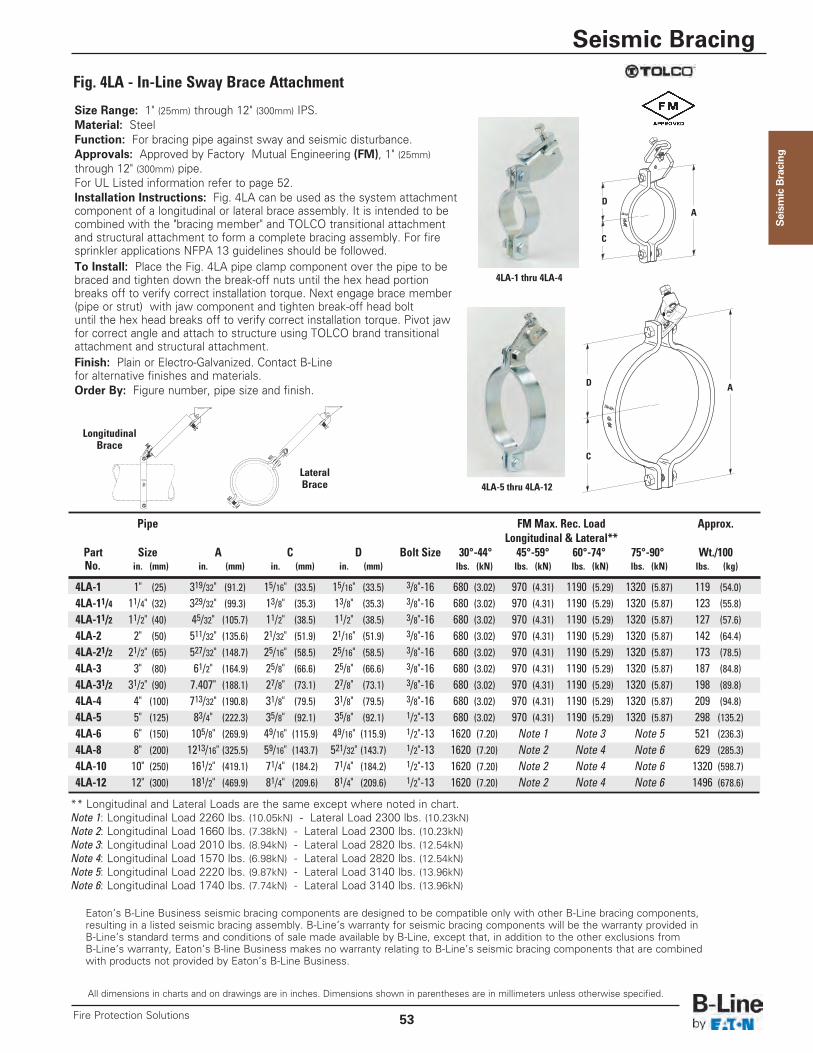
LongitudinalBrace
LateralBrace
Eaton’s B-Line Business seismic bracing components are designed to be compatible only with other B-Line bracing components, resulting in a listed seismic bracing assembly. B-Line’s warranty for seismic bracing components will be the warranty provided in B-Line’s standard terms and conditions of sale made available by B-Line, except that, in addition to the other exclusions from B-Line’s warranty, Eaton’s B-line Business makes no warranty relating to B-Line’s seismic bracing components that are combined with products not provided by Eaton’s B-Line Business.
Size Range: 1" (25mm) through 12" (300mm) IPS.Material: SteelFunction: For bracing pipe against sway and seismic disturbance.Approvals: Approved by Factory Mutual Engineering (FM), 1" (25mm)through 12" (300mm) pipe.For UL Listed information refer to page 52.Installation Instructions: Fig. 4LA can be used as the system attachmentcomponent of a longitudinal or lateral brace assembly. It is intended to becombined with the "bracing member" and TOLCO transitional attachmentand structural attachment to form a complete bracing assembly. For firesprinkler applications NFPA 13 guidelines should be followed.To Install: Place the Fig. 4LA pipe clamp component over the pipe to bebraced and tighten down the break-off nuts until the hex head portionbreaks off to verify correct installation torque. Next engage brace member(pipe or strut) with jaw component and tighten break-off head boltuntil the hex head breaks off to verify correct installation torque. Pivot jawfor correct angle and attach to structure using TOLCO brand transitionalattachment and structural attachment.Finish: Plain or Electro-Galvanized. Contact B-Linefor alternative finishes and materials.Order By: Figure number, pipe size and finish.
Fig. 4LA - In-Line Sway Brace Attachment
4LA-1 thru 4LA-4
4LA-5 thru 4LA-12
Pipe FM Max. Rec. Load Approx.Longitudinal & Lateral**
Part Size A C D Bolt Size 30°-44° 45°-59° 60°-74° 75°-90° Wt./100No. in. (mm) in. (mm) in. (mm) in. (mm) lbs. (kN) lbs. (kN) lbs. (kN) lbs. (kN) lbs. (kg)
4LA-1 1" (25) 319/32" (91.2) 15/16" (33.5) 15/16" (33.5) 3/8"-16 680 (3.02) 970 (4.31) 1190 (5.29) 1320 (5.87) 119 (54.0)4LA-11/4 11/4" (32) 329/32" (99.3) 13/8" (35.3) 13/8" (35.3) 3/8"-16 680 (3.02) 970 (4.31) 1190 (5.29) 1320 (5.87) 123 (55.8)4LA-11/2 11/2" (40) 45/32" (105.7) 11/2" (38.5) 11/2" (38.5) 3/8"-16 680 (3.02) 970 (4.31) 1190 (5.29) 1320 (5.87) 127 (57.6)4LA-2 2" (50) 511/32" (135.6) 21/32" (51.9) 21/16" (51.9) 3/8"-16 680 (3.02) 970 (4.31) 1190 (5.29) 1320 (5.87) 142 (64.4)4LA-21/2 21/2" (65) 527/32" (148.7) 25/16" (58.5) 25/16" (58.5) 3/8"-16 680 (3.02) 970 (4.31) 1190 (5.29) 1320 (5.87) 173 (78.5)4LA-3 3" (80) 61/2" (164.9) 25/8" (66.6) 25/8" (66.6) 3/8"-16 680 (3.02) 970 (4.31) 1190 (5.29) 1320 (5.87) 187 (84.8)4LA-31/2 31/2" (90) 7.407" (188.1) 27/8" (73.1) 27/8" (73.1) 3/8"-16 680 (3.02) 970 (4.31) 1190 (5.29) 1320 (5.87) 198 (89.8)4LA-4 4" (100) 713/32" (190.8) 31/8" (79.5) 31/8" (79.5) 3/8"-16 680 (3.02) 970 (4.31) 1190 (5.29) 1320 (5.87) 209 (94.8)4LA-5 5" (125) 83/4" (222.3) 35/8" (92.1) 35/8" (92.1) 1/2"-13 680 (3.02) 970 (4.31) 1190 (5.29) 1320 (5.87) 298 (135.2)4LA-6 6" (150) 105/8" (269.9) 49/16" (115.9) 49/16" (115.9) 1/2"-13 1620 (7.20) Note 1 Note 3 Note 5 521 (236.3)4LA-8 8" (200) 1213/16" (325.5) 59/16" (143.7) 521/32" (143.7) 1/2"-13 1620 (7.20) Note 2 Note 4 Note 6 629 (285.3)4LA-10 10" (250) 161/2" (419.1) 71/4" (184.2) 71/4" (184.2) 1/2"-13 1620 (7.20) Note 2 Note 4 Note 6 1320 (598.7)4LA-12 12" (300) 181/2" (469.9) 81/4" (209.6) 81/4" (209.6) 1/2"-13 1620 (7.20) Note 2 Note 4 Note 6 1496 (678.6)
** Longitudinal and Lateral Loads are the same except where noted in chart.Note 1: Longitudinal Load 2260 lbs. (10.05kN) - Lateral Load 2300 lbs. (10.23kN)Note 2: Longitudinal Load 1660 lbs. (7.38kN) - Lateral Load 2300 lbs. (10.23kN)Note 3: Longitudinal Load 2010 lbs. (8.94kN) - Lateral Load 2820 lbs. (12.54kN)Note 4: Longitudinal Load 1570 lbs. (6.98kN) - Lateral Load 2820 lbs. (12.54kN)Note 5: Longitudinal Load 2220 lbs. (9.87kN) - Lateral Load 3140 lbs. (13.96kN)Note 6: Longitudinal Load 1740 lbs. (7.74kN) - Lateral Load 3140 lbs. (13.96kN)
C
AD
C
AD
Seism
ic Bracing
All dimensions in charts and on drawings are in inches. Dimensions shown in parentheses are in millimeters unless otherwise specified.
Seismic Bracing
53Fire Protection Solutions
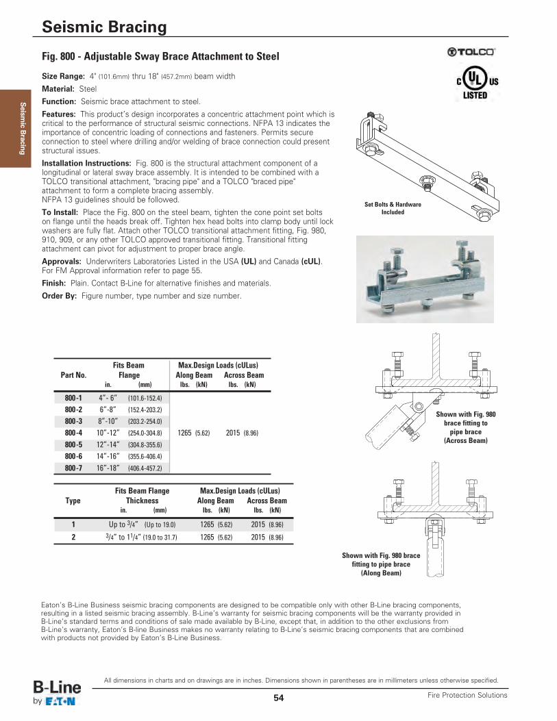
Seism
ic Bracing
Size Range: 4" (101.6mm) thru 18" (457.2mm) beam width
Material: Steel
Function: Seismic brace attachment to steel.
Features: This product’s design incorporates a concentric attachment point which iscritical to the performance of structural seismic connections. NFPA 13 indicates theimportance of concentric loading of connections and fasteners. Permits secureconnection to steel where drilling and/or welding of brace connection could presentstructural issues.
Installation Instructions: Fig. 800 is the structural attachment component of alongitudinal or lateral sway brace assembly. It is intended to be combined with aTOLCO transitional attachment, "bracing pipe" and a TOLCO "braced pipe"attachment to form a complete bracing assembly. NFPA 13 guidelines should be followed.
To Install: Place the Fig. 800 on the steel beam, tighten the cone point set boltson flange until the heads break off. Tighten hex head bolts into clamp body until lockwashers are fully flat. Attach other TOLCO transitional attachment fitting, Fig. 980,910, 909, or any other TOLCO approved transitional fitting. Transitional fittingattachment can pivot for adjustment to proper brace angle.
Approvals: Underwriters Laboratories Listed in the USA (UL) and Canada (cUL).For FM Approval information refer to page 55.
Finish: Plain. Contact B-Line for alternative finishes and materials.
Order By: Figure number, type number and size number.
Fig. 800 - Adjustable Sway Brace Attachment to Steel
Eaton’s B-Line Business seismic bracing components are designed to be compatible only with other B-Line bracing components, resulting in a listed seismic bracing assembly. B-Line’s warranty for seismic bracing components will be the warranty provided in B-Line’s standard terms and conditions of sale made available by B-Line, except that, in addition to the other exclusions from B-Line’s warranty, Eaton’s B-line Business makes no warranty relating to B-Line’s seismic bracing components that are combined with products not provided by Eaton’s B-Line Business.
Shown with Fig. 980brace fitting topipe brace
(Across Beam)
Shown with Fig. 980 bracefitting to pipe brace
(Along Beam)
Set Bolts & HardwareIncluded
Fits Beam Max.Design Loads (cULus)Part No. Flange Along Beam Across Beam
in. (mm) lbs. (kN) lbs. (kN)
800-1 4”- 6” (101.6-152.4)
800-2 6”-8” (152.4-203.2)
800-3 8”-10” (203.2-254.0)
800-4 10”-12” (254.0-304.8) 1265 (5.62) 2015 (8.96)800-5 12”-14” (304.8-355.6)
800-6 14”-16” (355.6-406.4)
800-7 16”-18” (406.4-457.2)
Fits Beam Flange Max.Design Loads (cULus)Type Thickness Along Beam Across Beam
in. (mm) lbs. (kN) lbs. (kN)
1 Up to 3/4” (Up to 19.0) 1265 (5.62) 2015 (8.96)
2 3/4” to 11/4” (19.0 to 31.7) 1265 (5.62) 2015 (8.96)
All dimensions in charts and on drawings are in inches. Dimensions shown in parentheses are in millimeters unless otherwise specified.
Seismic Bracing
Fire Protection Solutions54
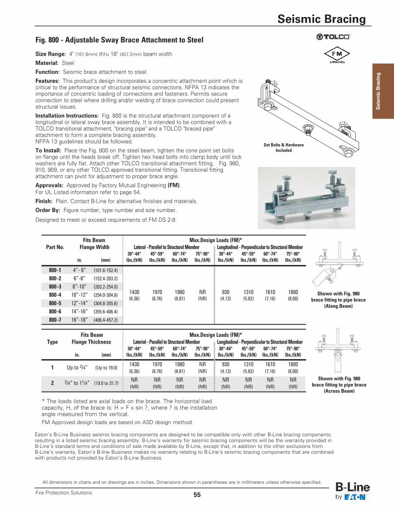
Seism
ic Bracing
Size Range: 4" (101.6mm) thru 18" (457.2mm) beam width
Material: Steel
Function: Seismic brace attachment to steel.
Features: This product’s design incorporates a concentric attachment point which iscritical to the performance of structural seismic connections. NFPA 13 indicates theimportance of concentric loading of connections and fasteners. Permits secureconnection to steel where drilling and/or welding of brace connection could presentstructural issues.
Installation Instructions: Fig. 800 is the structural attachment component of alongitudinal or lateral sway brace assembly. It is intended to be combined with aTOLCO transitional attachment, "bracing pipe" and a TOLCO "braced pipe"attachment to form a complete bracing assembly. NFPA 13 guidelines should be followed.
To Install: Place the Fig. 800 on the steel beam, tighten the cone point set boltson flange until the heads break off. Tighten hex head bolts into clamp body until lockwashers are fully flat. Attach other TOLCO transitional attachment fitting, Fig. 980,910, 909, or any other TOLCO approved transitional fitting. Transitional fittingattachment can pivot for adjustment to proper brace angle.
Approvals: Approved by Factory Mutual Engineering (FM). For UL Listed information refer to page 54.
Finish: Plain. Contact B-Line for alternative finishes and materials.
Order By: Figure number, type number and size number.
Designed to meet or exceed requirements of FM DS 2-8.
Fig. 800 - Adjustable Sway Brace Attachment to Steel
Fits Beam Max.Design Loads (FM)*Part No. Flange Width Lateral - Parallel to Structural Member Longitudinal - Perpendicular to Structural Member
30°-44° 45°-59° 60°-74° 75°-90° 30°-44° 45°-59° 60°-74° 75°-90°in. (mm) lbs./(kN) lbs./(kN) lbs./(kN) lbs./(kN) lbs./(kN) lbs./(kN) lbs./(kN) lbs./(kN)
800-1 4”- 6” (101.6-152.4)
800-2 6”-8” (152.4-203.2)
800-3 8”-10” (203.2-254.0)1430 1970 1980 NR 930 1310 1610 1800800-4 10”-12” (254.0-304.8)(6.36) (8.76) (8.81) (NR) (4.13) (5.82) (7.16) (8.00)
800-5 12”-14” (304.8-355.6)
800-6 14”-16” (355.6-406.4)
800-7 16”-18” (406.4-457.2)
Fits Beam Max.Design Loads (FM)*Type Flange Thickness Laterial - Parallel to Structural Member Longitudinal - Perpendicular to Structural Member
30°-44° 45°-59° 60°-74° 75°-90° 30°-44° 45°-59° 60°-74° 75°-90°in. (mm) lbs./(kN) lbs./(kN) lbs./(kN) lbs./(kN) lbs./(kN) lbs./(kN) lbs./(kN) lbs./(kN)
1 Up to 3/4” (Up to 19.0)1430 1970 1980 NR 930 1310 1610 1800(6.36) (8.76) (8.81) (NR) (4.13) (5.82) (7.16) (8.00)
2 3/4” to 11/4” (19.0 to 31.7)NR NR NR NR NR NR NR NR(NR) (NR) (NR) (NR) (NR) (NR) (NR) (NR)
* The loads listed are axial loads on the brace. The horizontal loadcapacity, H, of the brace is: H = F x sin ?, where ? is the installationangle measured from the vertical.FM Approved design loads are based on ASD design method.
Eaton’s B-Line Business seismic bracing components are designed to be compatible only with other B-Line bracing components, resulting in a listed seismic bracing assembly. B-Line’s warranty for seismic bracing components will be the warranty provided in B-Line’s standard terms and conditions of sale made available by B-Line, except that, in addition to the other exclusions from B-Line’s warranty, Eaton’s B-line Business makes no warranty relating to B-Line’s seismic bracing components that are combined with products not provided by Eaton’s B-Line Business.
Shown with Fig. 980brace fitting to pipe brace
(Along Beam)
Shown with Fig. 980brace fitting to pipe brace
(Across Beam)
Set Bolts & HardwareIncluded
All dimensions in charts and on drawings are in inches. Dimensions shown in parentheses are in millimeters unless otherwise specified.
Seismic Bracing
55Fire Protection Solutions
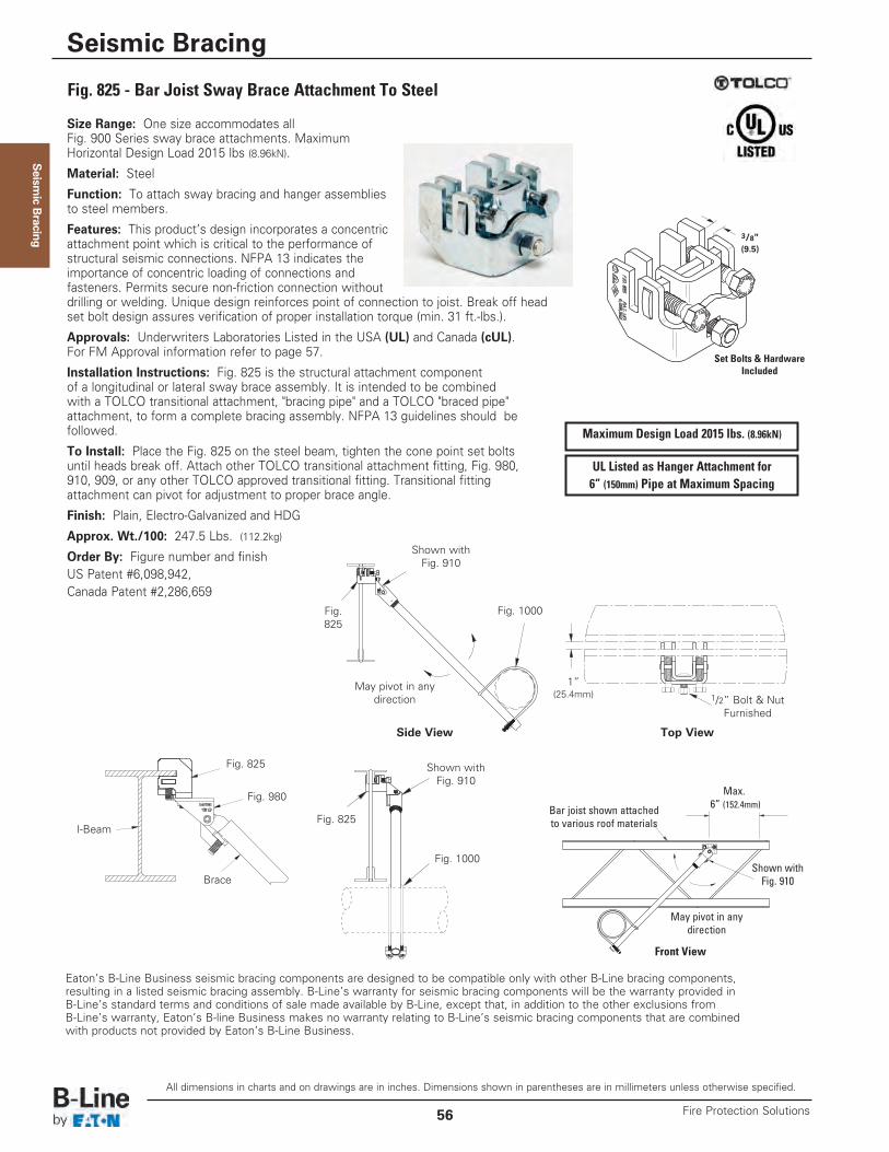
Seism
ic Bracing
Size Range: One size accommodates all Fig. 900 Series sway brace attachments. MaximumHorizontal Design Load 2015 lbs (8.96kN).
Material: Steel
Function: To attach sway bracing and hanger assembliesto steel members.
Features: This product’s design incorporates a concentricattachment point which is critical to the performance ofstructural seismic connections. NFPA 13 indicates the importance of concentric loading of connections and fasteners. Permits secure non-friction connection withoutdrilling or welding. Unique design reinforces point of connection to joist. Break off headset bolt design assures verification of proper installation torque (min. 31 ft.-lbs.).
Approvals: Underwriters Laboratories Listed in the USA (UL) and Canada (cUL).For FM Approval information refer to page 57.
Installation Instructions: Fig. 825 is the structural attachment componentof a longitudinal or lateral sway brace assembly. It is intended to be combinedwith a TOLCO transitional attachment, "bracing pipe" and a TOLCO "braced pipe"attachment, to form a complete bracing assembly. NFPA 13 guidelines should befollowed.
To Install: Place the Fig. 825 on the steel beam, tighten the cone point set boltsuntil heads break off. Attach other TOLCO transitional attachment fitting, Fig. 980,910, 909, or any other TOLCO approved transitional fitting. Transitional fittingattachment can pivot for adjustment to proper brace angle.
Finish: Plain, Electro-Galvanized and HDG
Approx. Wt./100: 247.5 Lbs. (112.2kg)
Order By: Figure number and finishUS Patent #6,098,942,Canada Patent #2,286,659
Eaton’s B-Line Business seismic bracing components are designed to be compatible only with other B-Line bracing components, resulting in a listed seismic bracing assembly. B-Line’s warranty for seismic bracing components will be the warranty provided in B-Line’s standard terms and conditions of sale made available by B-Line, except that, in addition to the other exclusions from B-Line’s warranty, Eaton’s B-line Business makes no warranty relating to B-Line’s seismic bracing components that are combined with products not provided by Eaton’s B-Line Business.
Fig. 825 - Bar Joist Sway Brace Attachment To Steel
Maximum Design Load 2015 lbs. (8.96kN)
UL Listed as Hanger Attachment for6” (150mm) Pipe at Maximum Spacing
Front View
May pivot in anydirection
Max.6” (152.4mm)
Shown withFig. 910
Bar joist shown attachedto various roof materials
Top View
1”(25.4mm) 1/2” Bolt & Nut
Furnished
Fig.825
Fig. 825
Fig. 980
Brace
I-BeamFig. 825
Fig. 1000
Fig. 1000
Side View
Shown withFig. 910
May pivot in anydirection
Shown withFig. 910
3/8"(9.5)
Set Bolts & HardwareIncluded
All dimensions in charts and on drawings are in inches. Dimensions shown in parentheses are in millimeters unless otherwise specified.
Seismic Bracing
Fire Protection Solutions56
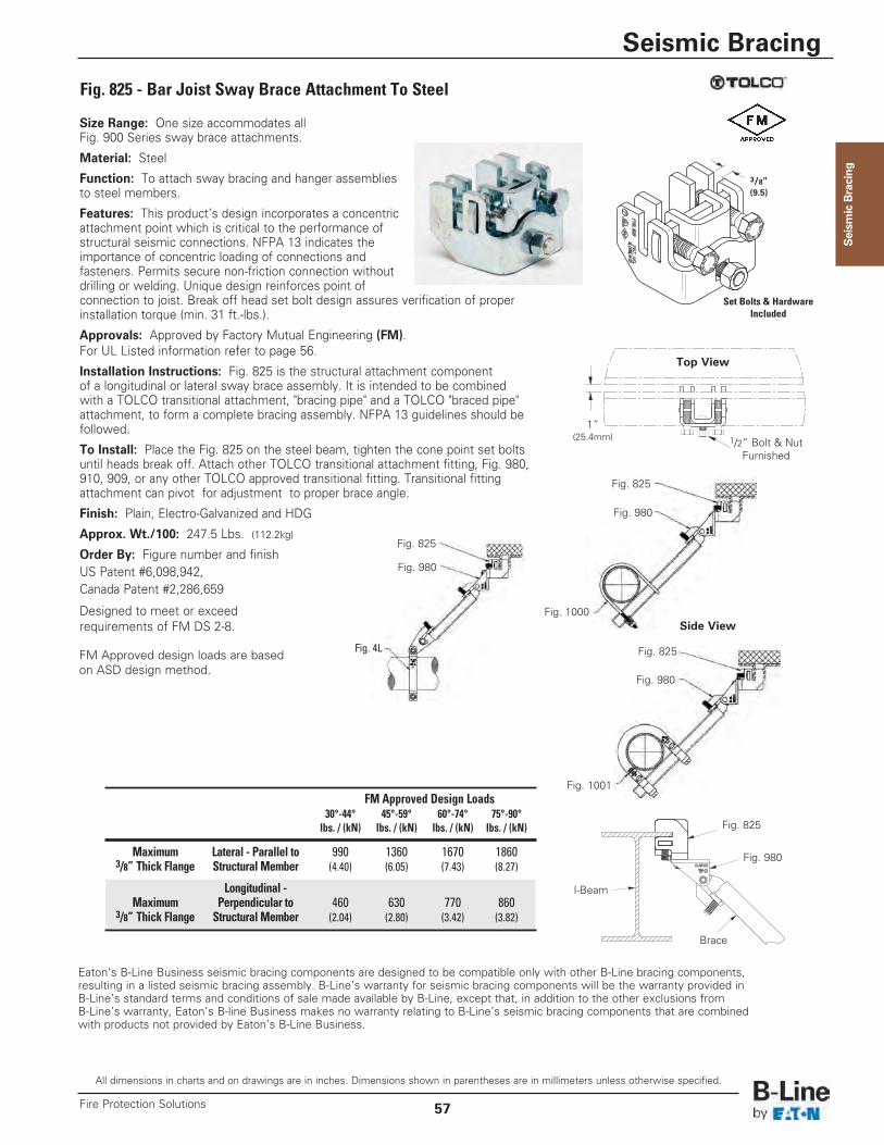
Seism
ic Bracing
Size Range: One size accommodates all Fig. 900 Series sway brace attachments.
Material: Steel
Function: To attach sway bracing and hanger assembliesto steel members.
Features: This product’s design incorporates a concentricattachment point which is critical to the performance ofstructural seismic connections. NFPA 13 indicates the importance of concentric loading of connections and fasteners. Permits secure non-friction connection withoutdrilling or welding. Unique design reinforces point ofconnection to joist. Break off head set bolt design assures verification of properinstallation torque (min. 31 ft.-lbs.).
Approvals: Approved by Factory Mutual Engineering (FM).For UL Listed information refer to page 56.
Installation Instructions: Fig. 825 is the structural attachment componentof a longitudinal or lateral sway brace assembly. It is intended to be combinedwith a TOLCO transitional attachment, "bracing pipe" and a TOLCO "braced pipe"attachment, to form a complete bracing assembly. NFPA 13 guidelines should befollowed.
To Install: Place the Fig. 825 on the steel beam, tighten the cone point set boltsuntil heads break off. Attach other TOLCO transitional attachment fitting, Fig. 980,910, 909, or any other TOLCO approved transitional fitting. Transitional fittingattachment can pivot for adjustment to proper brace angle.
Finish: Plain, Electro-Galvanized and HDG
Approx. Wt./100: 247.5 Lbs. (112.2kg)
Order By: Figure number and finishUS Patent #6,098,942,Canada Patent #2,286,659
Designed to meet or exceed requirements of FM DS 2-8.
Eaton’s B-Line Business seismic bracing components are designed to be compatible only with other B-Line bracing components, resulting in a listed seismic bracing assembly. B-Line’s warranty for seismic bracing components will be the warranty provided in B-Line’s standard terms and conditions of sale made available by B-Line, except that, in addition to the other exclusions from B-Line’s warranty, Eaton’s B-line Business makes no warranty relating to B-Line’s seismic bracing components that are combined with products not provided by Eaton’s B-Line Business.
Fig. 825 - Bar Joist Sway Brace Attachment To Steel
Fig. 4L
Top View
1”(25.4mm) 1/2” Bolt & Nut
Furnished
Fig. 825
Fig. 825
Fig. 825
Fig. 1000
Fig. 1001
Side View
Fig. 980
Fig. 980
Fig. 980
3/8"(9.5)
FM Approved design loads are basedon ASD design method.
Set Bolts & HardwareIncluded
Fig. 825
Fig. 980
Brace
I-Beam
FM Approved Design Loads30°-44° 45°-59° 60°-74° 75°-90°lbs. / (kN) lbs. / (kN) lbs. / (kN) lbs. / (kN)
Maximum Lateral - Parallel to 990 1360 1670 18603/8” Thick Flange Structural Member (4.40) (6.05) (7.43) (8.27)
Longitudinal -Maximum Perpendicular to 460 630 770 860
3/8” Thick Flange Structural Member (2.04) (2.80) (3.42) (3.82)
All dimensions in charts and on drawings are in inches. Dimensions shown in parentheses are in millimeters unless otherwise specified.
Seismic Bracing
57Fire Protection Solutions
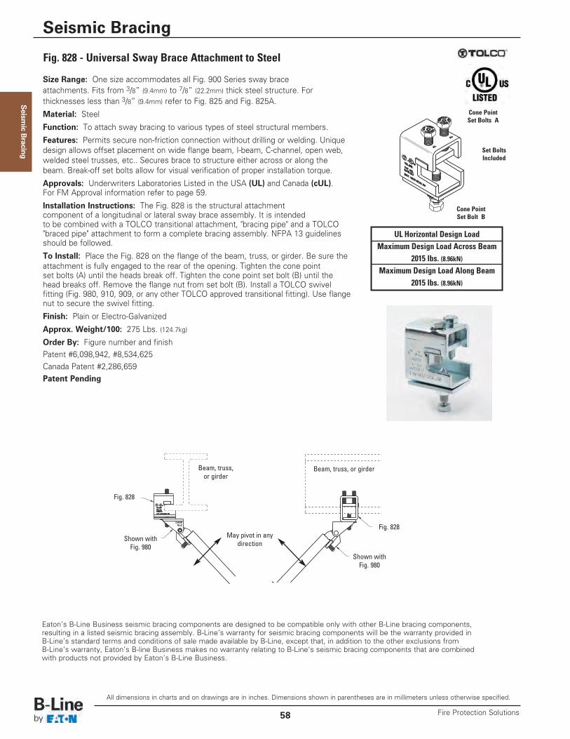
Seism
ic Bracing
Size Range: One size accommodates all Fig. 900 Series sway braceattachments. Fits from 3/8” (9.4mm) to 7/8” (22.2mm) thick steel structure. For thicknesses less than 3/8” (9.4mm) refer to Fig. 825 and Fig. 825A.
Material: Steel
Function: To attach sway bracing to various types of steel structural members.
Features: Permits secure non-friction connection without drilling or welding. Uniquedesign allows offset placement on wide flange beam, I-beam, C-channel, open web,welded steel trusses, etc.. Secures brace to structure either across or along thebeam. Break-off set bolts allow for visual verification of proper installation torque.
Approvals: Underwriters Laboratories Listed in the USA (UL) and Canada (cUL). For FM Approval information refer to page 59.
Installation Instructions: The Fig. 828 is the structural attachmentcomponent of a longitudinal or lateral sway brace assembly. It is intendedto be combined with a TOLCO transitional attachment, "bracing pipe" and a TOLCO"braced pipe" attachment to form a complete bracing assembly. NFPA 13 guidelinesshould be followed.
To Install: Place the Fig. 828 on the flange of the beam, truss, or girder. Be sure theattachment is fully engaged to the rear of the opening. Tighten the cone pointset bolts (A) until the heads break off. Tighten the cone point set bolt (B) until thehead breaks off. Remove the flange nut from set bolt (B). Install a TOLCO swivelfitting (Fig. 980, 910, 909, or any other TOLCO approved transitional fitting). Use flangenut to secure the swivel fitting.
Finish: Plain or Electro-Galvanized
Approx. Weight/100: 275 Lbs. (124.7kg)
Order By: Figure number and finishPatent #6,098,942, #8,534,625Canada Patent #2,286,659Patent Pending
Eaton’s B-Line Business seismic bracing components are designed to be compatible only with other B-Line bracing components, resulting in a listed seismic bracing assembly. B-Line’s warranty for seismic bracing components will be the warranty provided in B-Line’s standard terms and conditions of sale made available by B-Line, except that, in addition to the other exclusions from B-Line’s warranty, Eaton’s B-line Business makes no warranty relating to B-Line’s seismic bracing components that are combined with products not provided by Eaton’s B-Line Business.
Shown withFig. 980
Shown withFig. 980
May pivot in anydirection
Fig. 828
Fig. 828
Beam, truss, or girderBeam, truss,or girder
Fig. 828 - Universal Sway Brace Attachment to Steel
UL Horizontal Design LoadMaximum Design Load Across Beam
2015 lbs. (8.96kN)Maximum Design Load Along Beam
2015 lbs. (8.96kN)
Cone PointSet Bolts A
Cone PointSet Bolt B
Set BoltsIncluded
All dimensions in charts and on drawings are in inches. Dimensions shown in parentheses are in millimeters unless otherwise specified.
Seismic Bracing
Fire Protection Solutions58
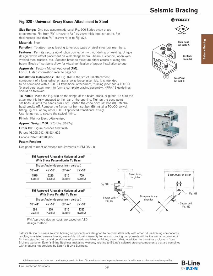
Seism
ic Bracing
Size Range: One size accommodates all Fig. 900 Series sway braceattachments. Fits from 3/8” (9.4mm) to 7/8” (22.2mm) thick steel structure. For thicknesses less than 3/8” (9.4mm) refer to Fig. 825.
Material: Steel
Function: To attach sway bracing to various types of steel structural members.
Features: Permits secure non-friction connection without drilling or welding. Uniquedesign allows offset placement on wide flange beam, I-beam, C-channel, open web,welded steel trusses, etc.. Secures brace to structure either across or along thebeam. Break-off set bolts allow for visual verification of proper installation torque.
Approvals: Factory Mutual Approved (FM).For UL Listed information refer to page 58.
Installation Instructions: The Fig. 828 is the structural attachmentcomponent of a longitudinal or lateral sway brace assembly. It is intendedto be combined with a TOLCO transitional attachment, "bracing pipe" and a TOLCO"braced pipe" attachment to form a complete bracing assembly. NFPA 13 guidelinesshould be followed.
To Install: Place the Fig. 828 on the flange of the beam, truss, or girder. Be sure theattachment is fully engaged to the rear of the opening. Tighten the cone pointset bolts (A) until the heads break off. Tighten the cone point set bolt (B) until thehead breaks off. Remove the flange nut from set bolt (B). Install a TOLCO swivelfitting Fig. 980 or any other TOLCO approved transitional fitting).Use flange nut to secure the swivel fitting.
Finish: Plain or Electro-Galvanized
Approx. Weight/100: 275 Lbs. (124.7kg)
Order By: Figure number and finishPatent #6,098,942, #8,534,625Canada Patent #2,286,659Patent Pending
Designed to meet or exceed requirements of FM DS 2-8.
Eaton’s B-Line Business seismic bracing components are designed to be compatible only with other B-Line bracing components, resulting in a listed seismic bracing assembly. B-Line’s warranty for seismic bracing components will be the warranty provided in B-Line’s standard terms and conditions of sale made available by B-Line, except that, in addition to the other exclusions from B-Line’s warranty, Eaton’s B-line Business makes no warranty relating to B-Line’s seismic bracing components that are combined with products not provided by Eaton’s B-Line Business.
Shown withFig. 980
Shown withFig. 980
May pivot in anydirection
Fig. 828
Fig. 828
Beam, truss, or girderBeam, truss,or girder
Fig. 828 - Universal Sway Brace Attachment to Steel
Cone PointSet Bolts A
Cone PointSet Bolt B
FM Approved Allowable Horizontal Load*With Brace Perpendicular To Beam
Brace Angle (degrees from vertical)30°-44° 45°-59° 60°-74° 75°-90°
1570 2220 1210 700(6.98kN) (9.87kN) (5.38kN) (3.11kN)
FM Approved Allowable Horizontal Load*With Brace Parallel To Beam
Brace Angle (degrees from vertical)30°-44° 45°-59° 60°-74° 75°-90°
690 970 1210 1330(3.07kN) (4.31kN) (5.38kN) (5.91kN)
Set BoltsIncluded
FM Approved design loads are based on ASDdesign method.
All dimensions in charts and on drawings are in inches. Dimensions shown in parentheses are in millimeters unless otherwise specified.
Seismic Bracing
59Fire Protection Solutions
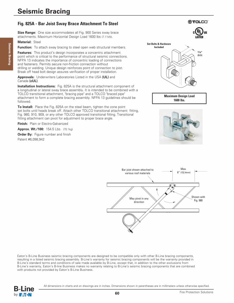
Seism
ic Bracing
Size Range: One size accommodates all Fig. 900 Series sway braceattachments. Maximum Horizontal Design Load 1600 lbs (7.11kN).
Material: Steel
Function: To attach sway bracing to steel open web structural members.
Features: This product’s design incorporates a concentric attachmentpoint which is critical to the performance of structural seismic connections.NFPA 13 indicates the importance of concentric loading of connectionsand fasteners. Permits secure non-friction connection withoutdrilling or welding. Unique design reinforces point of connection to joist.Break off head bolt design assures verification of proper installation.
Approvals: Underwriters Laboratories Listed in the USA (UL) andCanada (cUL).
Installation Instructions: Fig. 825A is the structural attachment component ofa longitudinal or lateral sway brace assembly. It is intended to be combined with aTOLCO transitional attachment, "bracing pipe" and a TOLCO "braced pipe"attachment to form a complete bracing assembly. NFPA 13 guidelines should befollowed.
To Install: Place the Fig. 825A on the steel beam, tighten the cone pointset bolts until heads break off. Attach other TOLCO transitional attachment fitting,Fig. 980, 910, 909, or any other TOLCO approved transitional fitting. Transitionalfitting attachment can pivot for adjustment to proper brace angle.
Finish: Plain or Electro-Galvanized
Approx. Wt./100: 154.5 Lbs. (70.1kg)
Order By: Figure number and finishPatent #6,098,942
Eaton’s B-Line Business seismic bracing components are designed to be compatible only with other B-Line bracing components, resulting in a listed seismic bracing assembly. B-Line’s warranty for seismic bracing components will be the warranty provided in B-Line’s standard terms and conditions of sale made available by B-Line, except that, in addition to the other exclusions from B-Line’s warranty, Eaton’s B-line Business makes no warranty relating to B-Line’s seismic bracing components that are combined with products not provided by Eaton’s B-Line Business.
Shown withFig. 980
May pivot in anydirection
Max.6” (152.4mm)
Bar joist shown attached tovarious roof materials
Fig. 825A - Bar Joist Sway Brace Attachment To Steel
Maximum Design Load1600 lbs.
3/8"(9.5)
Set Bolts & HardwareIncluded
All dimensions in charts and on drawings are in inches. Dimensions shown in parentheses are in millimeters unless otherwise specified.
Seismic Bracing
Fire Protection Solutions60
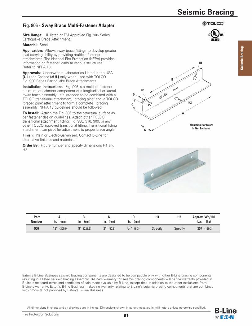
Seism
ic Bracing
Size Range: UL listed or FM Approved Fig. 906 SeriesEarthquake Brace Attachment.
Material: Steel
Application: Allows sway brace fittings to develop greaterload carrying ability by providing multiple fastenerattachments. The National Fire Protection (NFPA) providesinformation on fastener loads to various structures. Refer to NFPA 13.
Approvals: Underwriters Laboratories Listed in the USA(UL) and Canada (cUL) only when used with TOLCOFig. 900 Series Earthquake Brace Attachments.
Installation Instructions: Fig. 906 is a multiple fastenerstructural attachment component of a longitudinal or lateralsway brace assembly. It is intended to be combined with aTOLCO transitional attachment, "bracing pipe" and a TOLCO"braced pipe" attachment to form a complete bracingassembly. NFPA 13 guidelines should be followed.
To Install: Attach the Fig. 906 to the structural surface asper fastener design guidelines. Attach other TOLCOtransitional attachment fitting, Fig. 980, 910, 909, or anyother TOLCO approved transitional fitting. Transitional fittingattachment can pivot for adjustment to proper brace angle.
Finish: Plain or Electro-Galvanized. Contact B-Line foralternative finishes and materials.
Order By: Figure number and specify dimensions H1 andH2.
Eaton’s B-Line Business seismic bracing components are designed to be compatible only with other B-Line bracing components, resulting in a listed seismic bracing assembly. B-Line’s warranty for seismic bracing components will be the warranty provided in B-Line’s standard terms and conditions of sale made available by B-Line, except that, in addition to the other exclusions from B-Line’s warranty, Eaton’s B-line Business makes no warranty relating to B-Line’s seismic bracing components that are combined with products not provided by Eaton’s B-Line Business.
Fig. 906 - Sway Brace Multi-Fastener Adapter
Part A B C D H1 H2 Approx. Wt./100Number in. (mm) in. (mm) in. (mm) in. (mm) Lbs. (kg)
906 12” (305.0) 9” (228.6) 2” (50.8) 1/4” (6.3) Specify Specify 307 (139.3)
C
C
A
D
B
H1
H1
H2
Mounting HardwareIs Not Included
All dimensions in charts and on drawings are in inches. Dimensions shown in parentheses are in millimeters unless otherwise specified.
Seismic Bracing
61Fire Protection Solutions
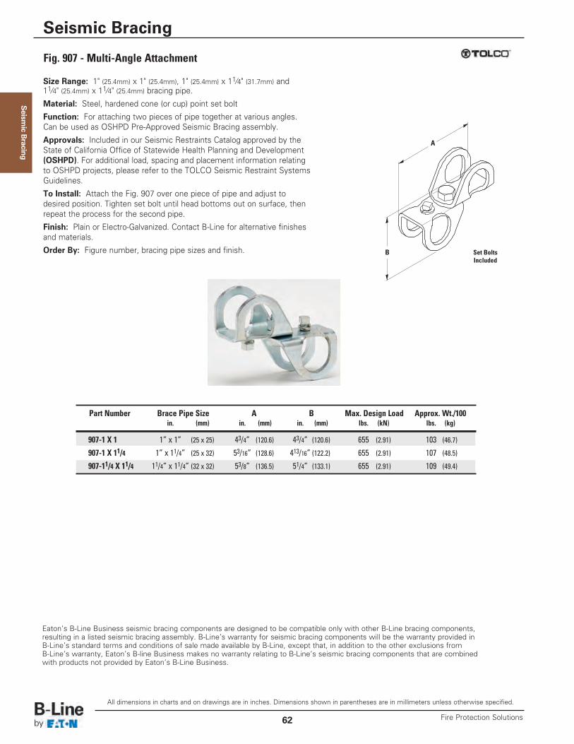
Seism
ic Bracing
Size Range: 1" (25.4mm) x 1" (25.4mm), 1" (25.4mm) x 11⁄4" (31.7mm) and 11⁄4" (25.4mm) x 11⁄4" (25.4mm) bracing pipe.
Material: Steel, hardened cone (or cup) point set bolt
Function: For attaching two pieces of pipe together at various angles.Can be used as OSHPD Pre-Approved Seismic Bracing assembly.
Approvals: Included in our Seismic Restraints Catalog approved by theState of California Office of Statewide Health Planning and Development(OSHPD). For additional load, spacing and placement information relatingto OSHPD projects, please refer to the TOLCO Seismic Restraint SystemsGuidelines.
To Install: Attach the Fig. 907 over one piece of pipe and adjust todesired position. Tighten set bolt until head bottoms out on surface, thenrepeat the process for the second pipe.
Finish: Plain or Electro-Galvanized. Contact B-Line for alternative finishesand materials.
Order By: Figure number, bracing pipe sizes and finish.
Eaton’s B-Line Business seismic bracing components are designed to be compatible only with other B-Line bracing components, resulting in a listed seismic bracing assembly. B-Line’s warranty for seismic bracing components will be the warranty provided in B-Line’s standard terms and conditions of sale made available by B-Line, except that, in addition to the other exclusions from B-Line’s warranty, Eaton’s B-line Business makes no warranty relating to B-Line’s seismic bracing components that are combined with products not provided by Eaton’s B-Line Business.
Fig. 907 - Multi-Angle Attachment
Part Number Brace Pipe Size A B Max. Design Load Approx. Wt./100in. (mm) in. (mm) in. (mm) lbs. (kN) lbs. (kg)
907-1 X 1 1” x 1” (25 x 25) 43/4” (120.6) 43/4” (120.6) 655 (2.91) 103 (46.7)
907-1 X 11/4 1” x 11/4” (25 x 32) 53/16” (128.6) 413/16” (122.2) 655 (2.91) 107 (48.5)
907-11/4 X 11/4 11/4” x 11/4” (32 x 32) 53/8” (136.5) 51/4” (133.1) 655 (2.91) 109 (49.4)
B
A
Set BoltsIncluded
All dimensions in charts and on drawings are in inches. Dimensions shown in parentheses are in millimeters unless otherwise specified.
Seismic Bracing
Fire Protection Solutions62
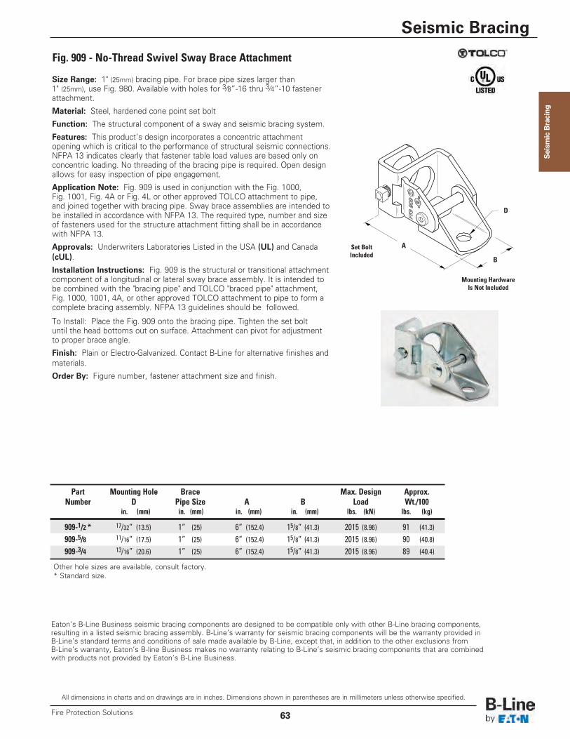
Seism
ic Bracing
Size Range: 1" (25mm) bracing pipe. For brace pipe sizes larger than1" (25mm), use Fig. 980. Available with holes for 3⁄8”-16 thru 3⁄4”-10 fastener attachment.
Material: Steel, hardened cone point set bolt
Function: The structural component of a sway and seismic bracing system.
Features: This product’s design incorporates a concentric attachmentopening which is critical to the performance of structural seismic connections.NFPA 13 indicates clearly that fastener table load values are based only onconcentric loading. No threading of the bracing pipe is required. Open designallows for easy inspection of pipe engagement.
Application Note: Fig. 909 is used in conjunction with the Fig. 1000,Fig. 1001, Fig. 4A or Fig. 4L or other approved TOLCO attachment to pipe,and joined together with bracing pipe. Sway brace assemblies are intended tobe installed in accordance with NFPA 13. The required type, number and sizeof fasteners used for the structure attachment fitting shall be in accordancewith NFPA 13.
Approvals: Underwriters Laboratories Listed in the USA (UL) and Canada(cUL).
Installation Instructions: Fig. 909 is the structural or transitional attachmentcomponent of a longitudinal or lateral sway brace assembly. It is intended tobe combined with the "bracing pipe" and TOLCO "braced pipe" attachment,Fig. 1000, 1001, 4A, or other approved TOLCO attachment to pipe to form acomplete bracing assembly. NFPA 13 guidelines should be followed.
To Install: Place the Fig. 909 onto the bracing pipe. Tighten the set boltuntil the head bottoms out on surface. Attachment can pivot for adjustmentto proper brace angle.
Finish: Plain or Electro-Galvanized. Contact B-Line for alternative finishes andmaterials.
Order By: Figure number, fastener attachment size and finish.
Eaton’s B-Line Business seismic bracing components are designed to be compatible only with other B-Line bracing components, resulting in a listed seismic bracing assembly. B-Line’s warranty for seismic bracing components will be the warranty provided in B-Line’s standard terms and conditions of sale made available by B-Line, except that, in addition to the other exclusions from B-Line’s warranty, Eaton’s B-line Business makes no warranty relating to B-Line’s seismic bracing components that are combined with products not provided by Eaton’s B-Line Business.
Fig. 909 - No-Thread Swivel Sway Brace Attachment
Part Mounting Hole Brace Max. Design Approx.Number D Pipe Size A B Load Wt./100
in. (mm) in. (mm) in. (mm) in. (mm) lbs. (kN) lbs. (kg)
909-1/2 * 17/32” (13.5) 1” (25) 6” (152.4) 15/8” (41.3) 2015 (8.96) 91 (41.3)
909-5/8 11/16” (17.5) 1” (25) 6” (152.4) 15/8” (41.3) 2015 (8.96) 90 (40.8)
909-3/4 13/16” (20.6) 1” (25) 6” (152.4) 15/8” (41.3) 2015 (8.96) 89 (40.4)
B
D
A
Mounting HardwareIs Not Included
Set BoltIncluded
Other hole sizes are available, consult factory.* Standard size.
All dimensions in charts and on drawings are in inches. Dimensions shown in parentheses are in millimeters unless otherwise specified.
Seismic Bracing
63Fire Protection Solutions
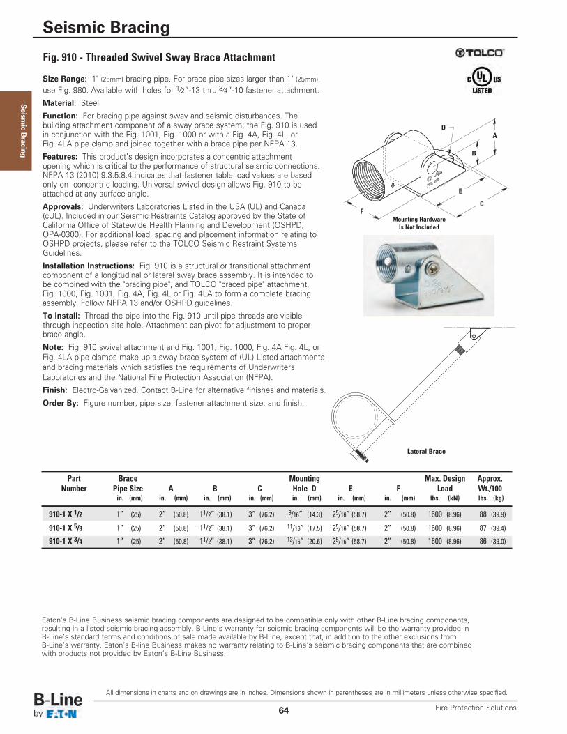
Seism
ic Bracing
Size Range: 1" (25mm) bracing pipe. For brace pipe sizes larger than 1" (25mm),use Fig. 980. Available with holes for 1⁄2”-13 thru 3⁄4”-10 fastener attachment.
Material: Steel
Function: For bracing pipe against sway and seismic disturbances. Thebuilding attachment component of a sway brace system; the Fig. 910 is usedin conjunction with the Fig. 1001, Fig. 1000 or with a Fig. 4A, Fig. 4L, orFig. 4LA pipe clamp and joined together with a brace pipe per NFPA 13.
Features: This product’s design incorporates a concentric attachmentopening which is critical to the performance of structural seismic connections.NFPA 13 (2010) 9.3.5.8.4 indicates that fastener table load values are basedonly on concentric loading. Universal swivel design allows Fig. 910 to beattached at any surface angle.
Approvals: Underwriters Laboratories Listed in the USA (UL) and Canada(cUL). Included in our Seismic Restraints Catalog approved by the State ofCalifornia Office of Statewide Health Planning and Development (OSHPD,OPA-0300). For additional load, spacing and placement information relating toOSHPD projects, please refer to the TOLCO Seismic Restraint SystemsGuidelines.
Installation Instructions: Fig. 910 is a structural or transitional attachmentcomponent of a longitudinal or lateral sway brace assembly. It is intended tobe combined with the "bracing pipe", and TOLCO "braced pipe" attachment,Fig. 1000, Fig. 1001, Fig. 4A, Fig. 4L or Fig. 4LA to form a complete bracingassembly. Follow NFPA 13 and/or OSHPD guidelines.
To Install: Thread the pipe into the Fig. 910 until pipe threads are visiblethrough inspection site hole. Attachment can pivot for adjustment to properbrace angle.
Note: Fig. 910 swivel attachment and Fig. 1001, Fig. 1000, Fig. 4A Fig. 4L, orFig. 4LA pipe clamps make up a sway brace system of (UL) Listed attachmentsand bracing materials which satisfies the requirements of UnderwritersLaboratories and the National Fire Protection Association (NFPA).
Finish: Electro-Galvanized. Contact B-Line for alternative finishes and materials.
Order By: Figure number, pipe size, fastener attachment size, and finish.
Eaton’s B-Line Business seismic bracing components are designed to be compatible only with other B-Line bracing components, resulting in a listed seismic bracing assembly. B-Line’s warranty for seismic bracing components will be the warranty provided in B-Line’s standard terms and conditions of sale made available by B-Line, except that, in addition to the other exclusions from B-Line’s warranty, Eaton’s B-line Business makes no warranty relating to B-Line’s seismic bracing components that are combined with products not provided by Eaton’s B-Line Business.
Lateral Brace
Fig. 910 - Threaded Swivel Sway Brace Attachment
Part Brace Mounting Max. Design Approx.Number Pipe Size A B C Hole D E F Load Wt./100
in. (mm) in. (mm) in. (mm) in. (mm) in. (mm) in. (mm) in. (mm) lbs. (kN) lbs. (kg)
910-1 X 1/2 1” (25) 2” (50.8) 11/2” (38.1) 3” (76.2) 9/16” (14.3) 25/16” (58.7) 2” (50.8) 1600 (8.96) 88 (39.9)
910-1 X 5/8 1” (25) 2” (50.8) 11/2” (38.1) 3” (76.2) 11/16” (17.5) 25/16” (58.7) 2” (50.8) 1600 (8.96) 87 (39.4)
910-1 X 3/4 1” (25) 2” (50.8) 11/2” (38.1) 3” (76.2) 13/16” (20.6) 25/16” (58.7) 2” (50.8) 1600 (8.96) 86 (39.0)
B
AD
F
E
C
Mounting HardwareIs Not Included
All dimensions in charts and on drawings are in inches. Dimensions shown in parentheses are in millimeters unless otherwise specified.
Seismic Bracing
Fire Protection Solutions64
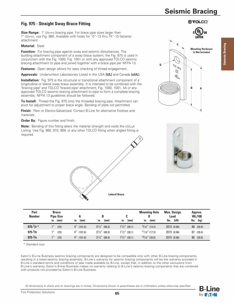
Seism
ic Bracing
Size Range: 1" (25mm) bracing pipe. For brace pipe sizes larger than1" (25mm), use Fig. 980. Available with holes for 1⁄2”-13 thru 3⁄4”-10 fastenerattachment.
Material: Steel
Function: For bracing pipe against sway and seismic disturbances. Thebuilding attachment component of a sway brace system; the Fig. 975 is used inconjunction with the Fig. 1000, Fig. 1001 or with any approved TOLCO seismicbracing attachment to pipe and joined together with a brace pipe per NFPA 13.
Features: Open design allows for easy checking of thread engagement.
Approvals: Underwriters Laboratories Listed in the USA (UL) and Canada (cUL).
Installation: Fig. 975 is the structural or transitional attachment component of alongitudinal or lateral sway brace assembly. It is intended to be combined with the"bracing pipe" and TOLCO "braced pipe" attachment, Fig. 1000, 1001, 4A or anyapproved TOLCO seismic bracing attachment to pipe to form a complete bracingassembly. NFPA 13 guidelines should be followed.
To Install: Thread the Fig. 975 onto the threaded bracing pipe. Attachment canpivot for adjustment to proper brace angle. Bending of plate not permitted.
Finish: Plain or Electro-Galvanized. Contact B-Line for alternative finishes andmaterials.
Order By: Figure number and finish.
Note: Bending of this fitting alters the material strength and voids the cULusListing. Use Fig. 980, 910, 909, or any other TOLCO fitting when angled fitting isrequired.
Eaton’s B-Line Business seismic bracing components are designed to be compatible only with other B-Line bracing components, resulting in a listed seismic bracing assembly. B-Line’s warranty for seismic bracing components will be the warranty provided in B-Line’s standard terms and conditions of sale made available by B-Line, except that, in addition to the other exclusions from B-Line’s warranty, Eaton’s B-line Business makes no warranty relating to B-Line’s seismic bracing components that are combined with products not provided by Eaton’s B-Line Business.
Lateral Brace
Fig. 975 - Straight Sway Brace Fitting
Part Brace Mounting Hole Max. Design Approx.Number Pipe Size A B C D Load Wt./100
in. (mm) in. (mm) in. (mm) in. (mm) in. (mm) lbs. (kN) lbs. (kg)
975-1/2 * 1” (25) 4” (101.6) 31/2” (88.9) 11/2” (38.1) 9/16” (14.3) 2015 (8.96) 88 (39.9)
975-5/8 1” (25) 4” (101.6) 31/2” (88.9) 11/2” (38.1) 11/16” (17.5) 2015 (8.96) 87 (39.4)
975-3/4 1” (25) 4” (101.6) 31/2” (88.9) 11/2” (38.1) 13/16” (20.6) 2015 (8.96) 86 (39.0)
B
D
C
A
Mounting HardwareIs Not Included
* Standard size.
All dimensions in charts and on drawings are in inches. Dimensions shown in parentheses are in millimeters unless otherwise specified.
Seismic Bracing
65Fire Protection Solutions
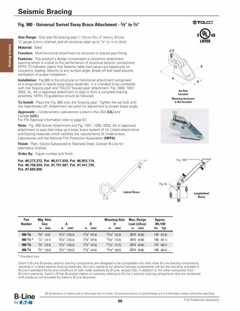
Seism
ic Bracing
Size Range: One size fits bracing pipe 1" (25mm) thru 2" (50mm), B-Line 12 gauge (2.6mm) channel, and all structural steel up to 1/4" (31.7mm) thick.
Material: Steel
Function: Multi-functional attachment to structure or braced pipe fitting.
Features: This product’s design incorporates a concentric attachmentopening which is critical to the performance of structural seismic connections.NFPA 13 indicates clearly that fastener table load values are based only onconcentric loading. Mounts to any surface angle. Break off bolt head assuresverification of proper installation.
Installation: Fig.980 is the structural or transitional attachment componentof a longitudinal or lateral sway brace assembly. It is intended to be combinedwith the "bracing pipe" and TOLCO "braced pipe" attachment, Fig. 1000, 1001,2002, 4L, 4A or approved attachment to pipe to form a complete bracingassembly. NFPA 13 guidelines should be followed.
To Install: Place the Fig. 980 onto the "bracing pipe". Tighten the set bolt untilthe head breaks off. Attachment can pivot for adjustment to proper brace angle.
Approvals: —Underwriters Laboratories Listed in the USA (UL) andCanada (cUL). For FM Approval information refer to page 67.
Note: Fig. 980 Swivel Attachment and Fig. 1001, 1000, 2002, 4A or approvedattachment to pipe that make up a sway brace system of UL Listed attachmentsand bracing materials which satisfies the requirements of UnderwritersLaboratories and the National Fire Protection Association (NFPA)
Finish: Plain, Electro-Galvanized or Stainless Steel. Contact B-Line foralternative finishes.
Order By: Figure number and finish.
Pat. #6,273,372, Pat. #6,517,030, Pat. #6,953,174,Pat. #6,708,930, Pat. #7,191,987, Pat. #7,441,730,Pat. #7,669,806
Eaton’s B-Line Business seismic bracing components are designed to be compatible only with other B-Line bracing components, resulting in a listed seismic bracing assembly. B-Line’s warranty for seismic bracing components will be the warranty provided in B-Line’s standard terms and conditions of sale made available by B-Line, except that, in addition to the other exclusions from B-Line’s warranty, Eaton’s B-line Business makes no warranty relating to B-Line’s seismic bracing components that are combined with products not provided by Eaton’s B-Line Business.
LongitudinalBrace
Lateral Brace
Fig. 980 - Universal Swivel Sway Brace Attachment - 3/8” to 3/4”
Part Mtg. Hdw. Mounting Hole Max. Design Approx.Number Size A B D Load (cULus) Wt./100
in. (mm) in. (mm) in. (mm) in. (mm) in. (mm) lbs. (kg)
980-3/8 3/8” (9.5) 51/4” (133.3) 17/8” (47.6) 13/32” (10.3) 2015 (8.96) 149 (67.6)
980-1/2 * 1/2” (12.7) 51/4” (133.3) 17/8” (47.6) 17/32” (13.5) 2015 (8.96) 148 (67.1)
980-5/8 5/8” (15.9) 51/4” (133.3) 17/8” (47.6) 11/16” (17.5) 2015 (8.96) 147 (66.7)
980-3/4 3/4” (19.0) 51/4” (133.3) 17/8” (47.6) 13/16” (20.5) 2015 (8.96) 146 (66.2)
* Standard size.
BA
Mounting HardwareIs Not Included
Set BoltIncluded
Fig. 4L
Fig. 980
D
All dimensions in charts and on drawings are in inches. Dimensions shown in parentheses are in millimeters unless otherwise specified.
Seismic Bracing
Fire Protection Solutions66
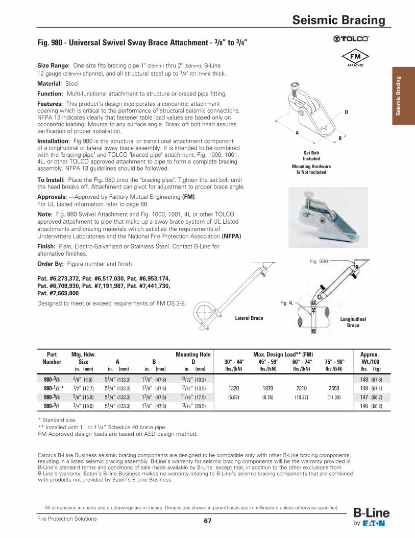
Seism
ic Bracing
Size Range: One size fits bracing pipe 1" (25mm) thru 2" (50mm), B-Line 12 gauge (2.6mm) channel, and all structural steel up to 1/4" (31.7mm) thick.
Material: Steel
Function: Multi-functional attachment to structure or braced pipe fitting.
Features: This product’s design incorporates a concentric attachmentopening which is critical to the performance of structural seismic connections.NFPA 13 indicates clearly that fastener table load values are based only onconcentric loading. Mounts to any surface angle. Break off bolt head assuresverification of proper installation.
Installation: Fig.980 is the structural or transitional attachment componentof a longitudinal or lateral sway brace assembly. It is intended to be combinedwith the "bracing pipe" and TOLCO "braced pipe" attachment, Fig. 1000, 1001,4L, or other TOLCO approved attachment to pipe to form a complete bracingassembly. NFPA 13 guidelines should be followed.
To Install: Place the Fig. 980 onto the "bracing pipe". Tighten the set bolt untilthe head breaks off. Attachment can pivot for adjustment to proper brace angle.
Approvals: —Approved by Factory Mutual Engineering (FM). For UL Listed information refer to page 66.
Note: Fig. 980 Swivel Attachment and Fig. 1000, 1001, 4L or other TOLCOapproved attachment to pipe that make up a sway brace system of UL Listedattachments and bracing materials which satisfies the requirements ofUnderwriters Laboratories and the National Fire Protection Association (NFPA)
Finish: Plain, Electro-Galvanized or Stainless Steel. Contact B-Line for alternative finishes.
Order By: Figure number and finish.
Pat. #6,273,372, Pat. #6,517,030, Pat. #6,953,174,Pat. #6,708,930, Pat. #7,191,987, Pat. #7,441,730,Pat. #7,669,806
Designed to meet or exceed requirements of FM DS 2-8.
Eaton’s B-Line Business seismic bracing components are designed to be compatible only with other B-Line bracing components, resulting in a listed seismic bracing assembly. B-Line’s warranty for seismic bracing components will be the warranty provided in B-Line’s standard terms and conditions of sale made available by B-Line, except that, in addition to the other exclusions from B-Line’s warranty, Eaton’s B-line Business makes no warranty relating to B-Line’s seismic bracing components that are combined with products not provided by Eaton’s B-Line Business.
Fig. 980 - Universal Swivel Sway Brace Attachment - 3/8” to 3/4”
* Standard size.** Installed with 1” or 11/4” Schedule 40 brace pipe.FM Approved design loads are based on ASD design method.
Part Mtg. Hdw. Mounting Hole Max. Design Load** (FM) Approx.Number Size A B D 30° - 44° 45° - 59° 60° - 74° 75° - 90° Wt./100
in. (mm) in. (mm) in. (mm) in. (mm) lbs./(kN) lbs./(kN) lbs./(kN) lbs./(kN) lbs. (kg)
980-3/8 3/8” (9.5) 51/4” (133.3) 17/8” (47.6) 13/32” (10.3) 149 (67.6)
980-1/2 * 1/2” (12.7) 51/4” (133.3) 17/8” (47.6) 17/32” (13.5) 1320 1970 2310 2550 148 (67.1)
980-5/8 5/8” (15.9) 51/4” (133.3) 17/8” (47.6) 11/16” (17.5) (5.87) (8.76) (10.27) (11.34) 147 (66.7)
980-3/4 3/4” (19.0) 51/4” (133.3) 17/8” (47.6) 13/16” (20.5) 146 (66.2)
Lateral Brace LongitudinalBrace
Fig. 4L
Fig. 980
Mounting HardwareIs Not Included
Set BoltIncluded
BA
D
All dimensions in charts and on drawings are in inches. Dimensions shown in parentheses are in millimeters unless otherwise specified.
Seismic Bracing
67Fire Protection Solutions
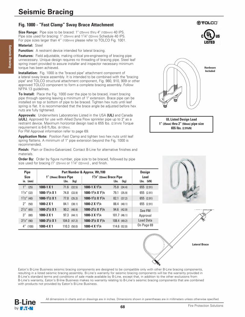
Seism
ic Bracing
Size Range: Pipe size to be braced: 1" (25mm) thru 4" (100mm) 40 IPS.Pipe size used for bracing: 1" (25mm) and 11⁄4" (32mm) Schedule 40 IPS. For pipe sizes larger than 4” (100mm) please refer to TOLCO Fig. 1001.Material: SteelFunction: A restraint device intended for lateral bracing.Features: Field adjustable, making critical pre-engineering of bracing pipeunnecessary. Unique design requires no threading of bracing pipe. Steel leafspring insert provided to assure installer and inspector necessary minimumtorque has been achieved.Installation: Fig. 1000 is the "braced pipe" attachment component ofa lateral sway brace assembly. It is intended to be combined with the "bracingpipe" and TOLCO structural attachment component, Fig. 980, 910, 909 or otherapproved TOLCO component to form a complete bracing assembly. FollowNFPA 13 guidelines.To Install: Place the Fig. 1000 over the pipe to be braced, insert bracingpipe through opening leaving a minimum of 1" extension. Brace pipe can beinstalled on top or bottom of pipe to be braced. Tighten hex nuts until leafspring is flat. It is recommended that the brace angle be adjusted before hexnuts are fully tightened.Approvals: Underwriters Laboratories Listed in the USA (UL) and Canada(cUL). Approved for use with Allied Dyna Flow sprinkler pipe up to 2" as arestraint device. Maximum horizontal design load is 655 lbs. (2.91kN) Torquerequirement is 6-8 ft./lbs. (8-10Nm).For FM Approval information refer to page 69.Application Note: Position Fast Clamp and tighten two hex nuts until leafspring flattens. A minimum of 1" pipe extension beyond the Fig. 1000 isrecommended.Finish: Plain or Electro-Galvanized. Contact B-Line for alternative finishes andmaterials.Order By: Order by figure number, pipe size to be braced, followed by pipesize used for bracing (1" (25mm) or 11⁄4" (32mm)) , and finish.
Eaton’s B-Line Business seismic bracing components are designed to be compatible only with other B-Line bracing components, resulting in a listed seismic bracing assembly. B-Line’s warranty for seismic bracing components will be the warranty provided in B-Line’s standard terms and conditions of sale made available by B-Line, except that, in addition to the other exclusions from B-Line’s warranty, Eaton’s B-line Business makes no warranty relating to B-Line’s seismic bracing components that are combined with products not provided by Eaton’s B-Line Business.
Lateral Brace
Fig. 1000 - “Fast Clamp” Sway Brace Attachment
UL Listed Design Load1” (25mm) thru 2” (50mm) pipe size
655 lbs. (2.91kN)
Pipe Part Number & Approx. Wt./100 DesignSize 1” (24mm) Brace Pipe 11/4” (32mm) Brace Pipe Loadin. (mm) Lbs. (kg) Lbs. (kg) Lbs. (kN)
1” (25) 1000-1 X 1 71.6 (32.5) 1000-1 X 11/4 75.8 (34.4) 655 (2.91)
11/4” (32) 1000-11/4 X 1 74.8 (33.9) 1000-11/4 X 11/4 79.1 (35.9) 655 (2.91)
11/2” (40) 1000-11/2 X 1 77.8 (35.3) 1000-11/2 X 11/4 82.1 (37.2) 655 (2.91)
2” (50) 1000-2 X 1 84.1 (38.1) 1000-2 X 11/4 88.4 (40.1) 655 (2.91)
21/2” (65) 1000-21/2 X 1 90.2 (40.9) 1000-21/2 X 11/4 94.6 (42.9) See FM3” (80) 1000-3 X 1 97.3 (44.1) 1000-3 X 11/4 101.7 (46.1) Approval31/2” (90) 1000-31/2 X 1 104.0 (47.2) 1000-31/2 X 11/4 108.4 (49.2) Load Data
4” (100) 1000-4 X 1 110.3 (50.0) 1000-4 X 11/4 114.6 (52.0) On Page 69
HardwareIncluded
All dimensions in charts and on drawings are in inches. Dimensions shown in parentheses are in millimeters unless otherwise specified.
Seismic Bracing
Fire Protection Solutions68
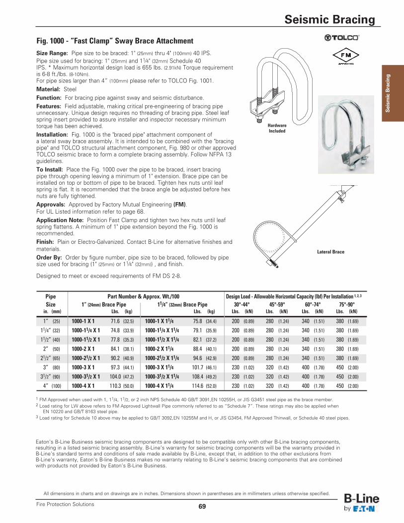
Seism
ic Bracing
Size Range: Pipe size to be braced: 1" (25mm) thru 4" (100mm) 40 IPS.Pipe size used for bracing: 1" (25mm) and 11⁄4" (32mm) Schedule 40IPS. * Maximum horizontal design load is 655 lbs. (2.91kN) Torque requirementis 6-8 ft./lbs. (8-10Nm).For pipe sizes larger than 4” (100mm) please refer to TOLCO Fig. 1001.Material: SteelFunction: For bracing pipe against sway and seismic disturbance.Features: Field adjustable, making critical pre-engineering of bracing pipeunnecessary. Unique design requires no threading of bracing pipe. Steel leafspring insert provided to assure installer and inspector necessary minimumtorque has been achieved.Installation: Fig. 1000 is the "braced pipe" attachment component ofa lateral sway brace assembly. It is intended to be combined with the "bracingpipe" and TOLCO structural attachment component, Fig. 980 or other approvedTOLCO seismic brace to form a complete bracing assembly. Follow NFPA 13guidelines.To Install: Place the Fig. 1000 over the pipe to be braced, insert bracingpipe through opening leaving a minimum of 1" extension. Brace pipe can beinstalled on top or bottom of pipe to be braced. Tighten hex nuts until leafspring is flat. It is recommended that the brace angle be adjusted before hexnuts are fully tightened.Approvals: Approved by Factory Mutual Engineering (FM). For UL Listed information refer to page 68.Application Note: Position Fast Clamp and tighten two hex nuts until leafspring flattens. A minimum of 1" pipe extension beyond the Fig. 1000 isrecommended.Finish: Plain or Electro-Galvanized. Contact B-Line for alternative finishes andmaterials.Order By: Order by figure number, pipe size to be braced, followed by pipesize used for bracing (1" (25mm) or 11⁄4" (32mm)) , and finish.
Designed to meet or exceed requirements of FM DS 2-8.
Eaton’s B-Line Business seismic bracing components are designed to be compatible only with other B-Line bracing components, resulting in a listed seismic bracing assembly. B-Line’s warranty for seismic bracing components will be the warranty provided in B-Line’s standard terms and conditions of sale made available by B-Line, except that, in addition to the other exclusions from B-Line’s warranty, Eaton’s B-line Business makes no warranty relating to B-Line’s seismic bracing components that are combined with products not provided by Eaton’s B-Line Business.
Lateral Brace
Fig. 1000 - “Fast Clamp” Sway Brace Attachment
HardwareIncluded
1 FM Approved when used with 1, 11/4, 11/2, or 2 inch NPS Schedule 40 GB/T 3091,EN 10255H, or JIS G3451 steel pipe as the brace member.2 Load rating for LW above refers to FM Approved Lightwall Pipe commonly referred to as “Schedule 7”. These ratings may also be applied when
EN 10220 and GB/T 8163 steel pipe.3 Load rating for Schedule 10 above may be applied to GB/T 3092,EN 10255M and H, or JIS G3454, FM Approved Thinwall, or Schedule 40 steel pipes.
Pipe Part Number & Approx. Wt./100 Design Load - Allowable Horizontal Capacity (lbf) Per Installation 1, 2, 3
Size 1” (24mm) Brace Pipe 11/4” (32mm) Brace Pipe 30°-44° 45°-59° 60°-74° 75°-90°in. (mm) Lbs. (kg) Lbs. (kg) Lbs. (kN) Lbs. (kN) Lbs. (kN) Lbs. (kN)
1” (25) 1000-1 X 1 71.6 (32.5) 1000-1 X 11/4 75.8 (34.4) 200 (0.89) 280 (1.24) 340 (1.51) 380 (1.69)
11/4” (32) 1000-11/4 X 1 74.8 (33.9) 1000-11/4 X 11/4 79.1 (35.9) 200 (0.89) 280 (1.24) 340 (1.51) 380 (1.69)
11/2” (40) 1000-11/2 X 1 77.8 (35.3) 1000-11/2 X 11/4 82.1 (37.2) 200 (0.89) 280 (1.24) 340 (1.51) 380 (1.69)
2” (50) 1000-2 X 1 84.1 (38.1) 1000-2 X 11/4 88.4 (40.1) 200 (0.89) 280 (1.24) 340 (1.51) 380 (1.69)
21/2” (65) 1000-21/2 X 1 90.2 (40.9) 1000-21/2 X 11/4 94.6 (42.9) 200 (0.89) 280 (1.24) 340 (1.51) 380 (1.69)
3” (80) 1000-3 X 1 97.3 (44.1) 1000-3 X 11/4 101.7 (46.1) 230 (1.02) 320 (1.42) 400 (1.78) 450 (2.00)
31/2” (90) 1000-31/2 X 1 104.0 (47.2) 1000-31/2 X 11/4 108.4 (49.2) 230 (1.02) 320 (1.42) 400 (1.78) 450 (2.00)
4” (100) 1000-4 X 1 110.3 (50.0) 1000-4 X 11/4 114.6 (52.0) 230 (1.02) 320 (1.42) 400 (1.78) 450 (2.00)
All dimensions in charts and on drawings are in inches. Dimensions shown in parentheses are in millimeters unless otherwise specified.
Seismic Bracing
69Fire Protection Solutions
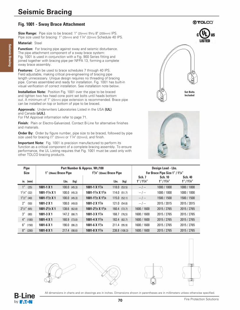
Seism
ic Bracing
Size Range: Pipe size to be braced: 1" (25mm) thru 8" (200mm) IPS.Pipe size used for bracing: 1" (25mm) and 11⁄4" (32mm) Schedule 40 IPS.
Material: Steel
Function: For bracing pipe against sway and seismic disturbance.The pipe attachment component of a sway brace system:Fig. 1001 is used in conjunction with a Fig. 900 Series fitting andjoined together with bracing pipe per NFPA 13, forming a completesway brace assembly.
Features: Can be used to brace schedules 7 through 40 IPS.Field adjustable, making critical pre-engineering of bracing pipelength unnecessary. Unique design requires no threading of bracingpipe. Comes assembled and ready for installation. Fig. 1001 has built-invisual verification of correct installation. See installation note below.
Installation Note: Position Fig. 1001 over the pipe to be bracedand tighten two hex head cone point set bolts until heads bottomout. A minimum of 1" (25mm) pipe extension is recommended. Brace pipecan be installed on top or bottom of pipe to be braced.
Approvals: Underwriters Laboratories Listed in the USA (UL)and Canada (cUL). For FM Approval information refer to page 71.
Finish: Plain or Electro-Galvanized. Contact B-Line for alternative finishesand materials.
Order By: Order by figure number, pipe size to be braced, followed by pipesize used for bracing (1" (25mm) or 11⁄4" (32mm)), and finish.
Important Note: Fig. 1001 is precision manufactured to perform itsfunction as a critical component of a complete bracing assembly. To ensureperformance, the UL Listing requires that Fig. 1001 must be used only withother TOLCO bracing products.
Fig. 1001 - Sway Brace Attachment
Set BoltsIncluded
All dimensions in charts and on drawings are in inches. Dimensions shown in parentheses are in millimeters unless otherwise specified.
Seismic Bracing
Fire Protection Solutions70
Pipe Part Number & Approx. Wt./100 Design Load - Lbs.Size 1” (24mm) Brace Pipe 11/4” (32mm) Brace Pipe For Brace Pipe Size 1” / 11/4”
Sch. 7 Sch. 10 Sch. 40in. (mm) Lbs. (kg) Lbs. (kg) 1” / 11/4” 1” / 11/4” 1” / 11/4”
1” (25) 1001-1 X 1 100.0 (45.3) 1001-1 X 11/4 118.0 (53.5) -- / -- 1000 / 1000 1000 / 100011/4” (32) 1001-11/4 X 1 100.0 (45.3) 1001-11/4 X 11/4 114.0 (51.7) -- / -- 1000 / 1000 1000 / 100011/2” (40) 1001-11/2 X 1 100.0 (45.3) 1001-11/2 X 11/4 115.0 (52.1) -- / -- 1500 / 1500 1500 / 15002” (50) 1001-2 X 1 108.0 (49.0) 1001-2 X 11/4 121.0 (54.8) -- / -- 2015 / 2015 2015 / 201521/2” (65) 1001-21/2 X 1 138.6 (62.8) 1001-21/2 X 11/4 160.4 (72.7) 1600 / 1600 2015 / 2765 2015 / 27653” (80) 1001-3 X 1 147.2 (66.7) 1001-3 X 11/4 168.7 (76,5) 1600 / 1600 2015 / 2765 2015 / 27654” (100) 1001-4 X 1 160.9 (73.0) 1001-4 X 11/4 182.4 (82.7) 1600 / 1600 2015 / 2765 2015 / 27656” (150) 1001-6 X 1 190.0 (86.2) 1001-6 X 11/4 211.4 (95.9) 1600 / 1600 2015 / 2765 2015 / 2765
8” (200) 1001-8 X 1 217.4 (98.6) 1001-8 X 11/4 238.8 (108.3) 1600 / 1600 2015 / 2765 2015 / 2765
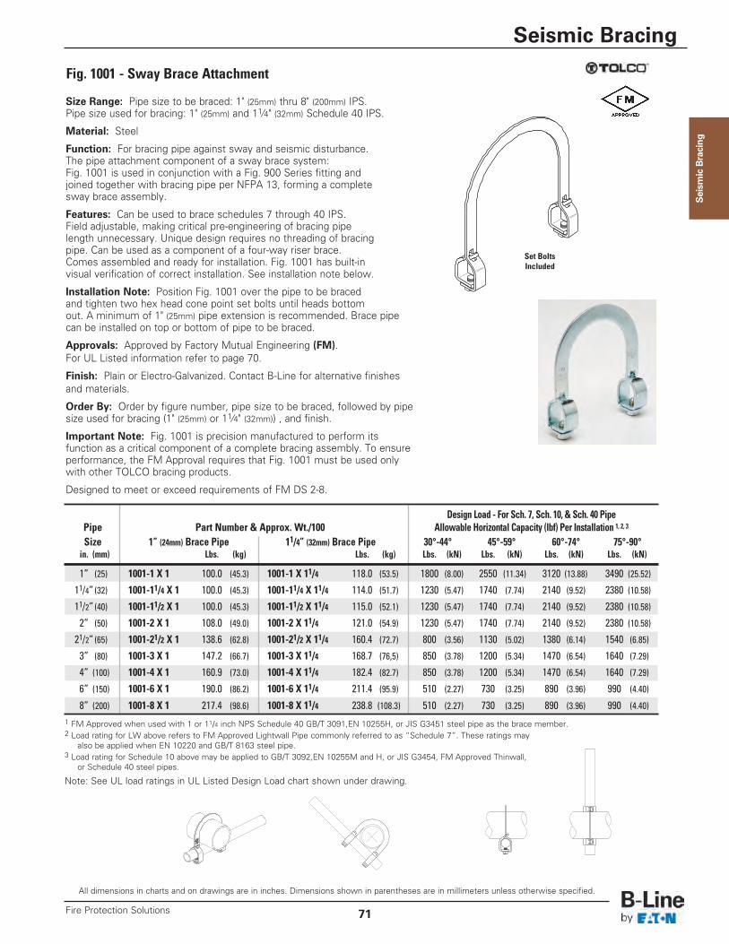
Seism
ic Bracing
Size Range: Pipe size to be braced: 1" (25mm) thru 8" (200mm) IPS.Pipe size used for bracing: 1" (25mm) and 11⁄4" (32mm) Schedule 40 IPS.
Material: Steel
Function: For bracing pipe against sway and seismic disturbance.The pipe attachment component of a sway brace system:Fig. 1001 is used in conjunction with a Fig. 900 Series fitting andjoined together with bracing pipe per NFPA 13, forming a completesway brace assembly.
Features: Can be used to brace schedules 7 through 40 IPS.Field adjustable, making critical pre-engineering of bracing pipelength unnecessary. Unique design requires no threading of bracingpipe. Can be used as a component of a four-way riser brace.Comes assembled and ready for installation. Fig. 1001 has built-invisual verification of correct installation. See installation note below.
Installation Note: Position Fig. 1001 over the pipe to be bracedand tighten two hex head cone point set bolts until heads bottomout. A minimum of 1" (25mm) pipe extension is recommended. Brace pipecan be installed on top or bottom of pipe to be braced.
Approvals: Approved by Factory Mutual Engineering (FM).For UL Listed information refer to page 70.
Finish: Plain or Electro-Galvanized. Contact B-Line for alternative finishesand materials.
Order By: Order by figure number, pipe size to be braced, followed by pipesize used for bracing (1" (25mm) or 11⁄4" (32mm)) , and finish.
Important Note: Fig. 1001 is precision manufactured to perform itsfunction as a critical component of a complete bracing assembly. To ensureperformance, the FM Approval requires that Fig. 1001 must be used onlywith other TOLCO bracing products.
Designed to meet or exceed requirements of FM DS 2-8.
Fig. 1001 - Sway Brace Attachment
Set BoltsIncluded
All dimensions in charts and on drawings are in inches. Dimensions shown in parentheses are in millimeters unless otherwise specified.
Seismic Bracing
71Fire Protection Solutions
Design Load - For Sch. 7, Sch. 10, & Sch. 40 PipePipe Part Number & Approx. Wt./100 Allowable Horizontal Capacity (lbf) Per Installation 1, 2, 3
Size 1” (24mm) Brace Pipe 11/4” (32mm) Brace Pipe 30°-44° 45°-59° 60°-74° 75°-90°in. (mm) Lbs. (kg) Lbs. (kg) Lbs. (kN) Lbs. (kN) Lbs. (kN) Lbs. (kN)
1” (25) 1001-1 X 1 100.0 (45.3) 1001-1 X 11/4 118.0 (53.5) 1800 (8.00) 2550 (11.34) 3120 (13.88) 3490 (25.52)
11/4” (32) 1001-11/4 X 1 100.0 (45.3) 1001-11/4 X 11/4 114.0 (51.7) 1230 (5.47) 1740 (7.74) 2140 (9.52) 2380 (10.58)
11/2” (40) 1001-11/2 X 1 100.0 (45.3) 1001-11/2 X 11/4 115.0 (52.1) 1230 (5.47) 1740 (7.74) 2140 (9.52) 2380 (10.58)
2” (50) 1001-2 X 1 108.0 (49.0) 1001-2 X 11/4 121.0 (54.9) 1230 (5.47) 1740 (7.74) 2140 (9.52) 2380 (10.58)
21/2” (65) 1001-21/2 X 1 138.6 (62.8) 1001-21/2 X 11/4 160.4 (72.7) 800 (3.56) 1130 (5.02) 1380 (6.14) 1540 (6.85)
3” (80) 1001-3 X 1 147.2 (66.7) 1001-3 X 11/4 168.7 (76,5) 850 (3.78) 1200 (5.34) 1470 (6.54) 1640 (7.29)
4” (100) 1001-4 X 1 160.9 (73.0) 1001-4 X 11/4 182.4 (82.7) 850 (3.78) 1200 (5.34) 1470 (6.54) 1640 (7.29)
6” (150) 1001-6 X 1 190.0 (86.2) 1001-6 X 11/4 211.4 (95.9) 510 (2.27) 730 (3.25) 890 (3.96) 990 (4.40)
8” (200) 1001-8 X 1 217.4 (98.6) 1001-8 X 11/4 238.8 (108.3) 510 (2.27) 730 (3.25) 890 (3.96) 990 (4.40)
1 FM Approved when used with 1 or 11/4 inch NPS Schedule 40 GB/T 3091,EN 10255H, or JIS G3451 steel pipe as the brace member.2 Load rating for LW above refers to FM Approved Lightwall Pipe commonly referred to as “Schedule 7”. These ratings may
also be applied when EN 10220 and GB/T 8163 steel pipe.3 Load rating for Schedule 10 above may be applied to GB/T 3092,EN 10255M and H, or JIS G3454, FM Approved Thinwall,
or Schedule 40 steel pipes.
Note: See UL load ratings in UL Listed Design Load chart shown under drawing.
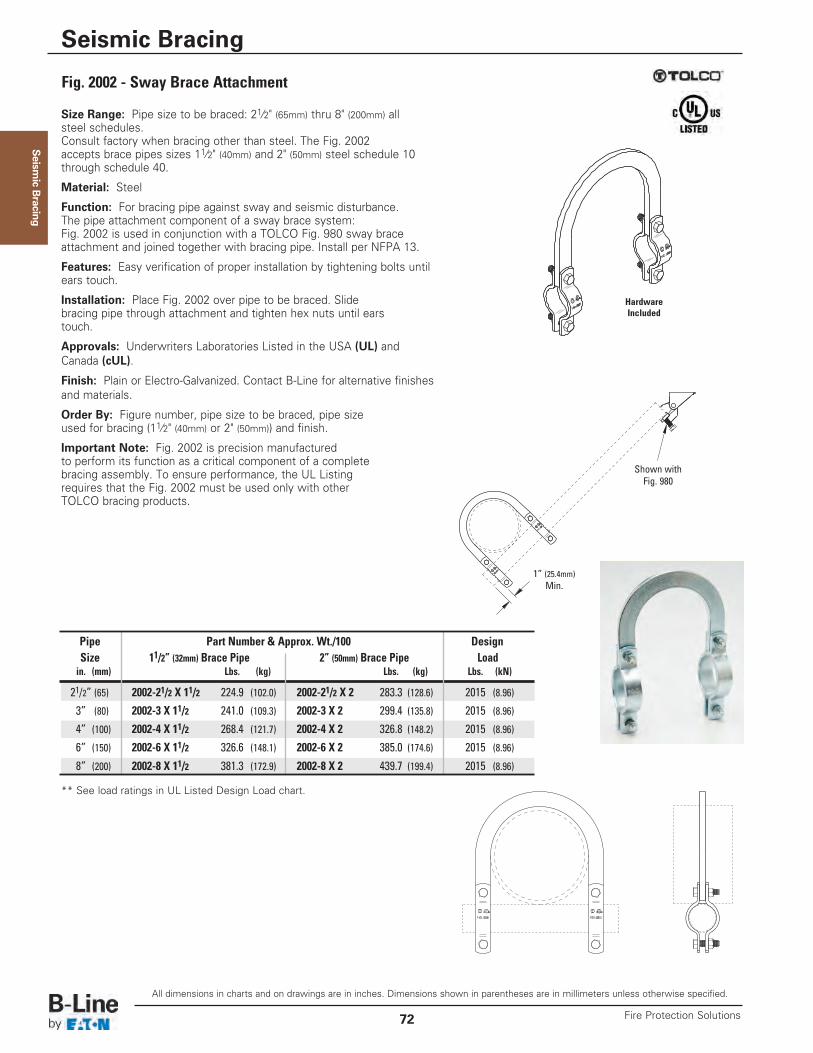
Seism
ic Bracing
Size Range: Pipe size to be braced: 21⁄2" (65mm) thru 8" (200mm) allsteel schedules.Consult factory when bracing other than steel. The Fig. 2002accepts brace pipes sizes 11⁄2" (40mm) and 2" (50mm) steel schedule 10through schedule 40.
Material: Steel
Function: For bracing pipe against sway and seismic disturbance.The pipe attachment component of a sway brace system:Fig. 2002 is used in conjunction with a TOLCO Fig. 980 sway braceattachment and joined together with bracing pipe. Install per NFPA 13.
Features: Easy verification of proper installation by tightening bolts untilears touch.
Installation: Place Fig. 2002 over pipe to be braced. Slidebracing pipe through attachment and tighten hex nuts until earstouch.
Approvals: Underwriters Laboratories Listed in the USA (UL) andCanada (cUL).
Finish: Plain or Electro-Galvanized. Contact B-Line for alternative finishesand materials.
Order By: Figure number, pipe size to be braced, pipe sizeused for bracing (11⁄2" (40mm) or 2" (50mm)) and finish.
Important Note: Fig. 2002 is precision manufacturedto perform its function as a critical component of a completebracing assembly. To ensure performance, the UL Listingrequires that the Fig. 2002 must be used only with otherTOLCO bracing products.
Fig. 2002 - Sway Brace Attachment
Shown withFig. 980
1” (25.4mm)Min.
** See load ratings in UL Listed Design Load chart.
Pipe Part Number & Approx. Wt./100 DesignSize 11/2” (32mm) Brace Pipe 2” (50mm) Brace Pipe Loadin. (mm) Lbs. (kg) Lbs. (kg) Lbs. (kN)
21/2” (65) 2002-21/2 X 11/2 224.9 (102.0) 2002-21/2 X 2 283.3 (128.6) 2015 (8.96)
3” (80) 2002-3 X 11/2 241.0 (109.3) 2002-3 X 2 299.4 (135.8) 2015 (8.96)
4” (100) 2002-4 X 11/2 268.4 (121.7) 2002-4 X 2 326.8 (148.2) 2015 (8.96)
6” (150) 2002-6 X 11/2 326.6 (148.1) 2002-6 X 2 385.0 (174.6) 2015 (8.96)
8” (200) 2002-8 X 11/2 381.3 (172.9) 2002-8 X 2 439.7 (199.4) 2015 (8.96)
HardwareIncluded
All dimensions in charts and on drawings are in inches. Dimensions shown in parentheses are in millimeters unless otherwise specified.
Seismic Bracing
Fire Protection Solutions72
Seism
ic Bracing
Notes
Seismic Bracing
73Fire Protection Solutions
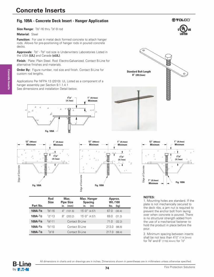
Concrete Inserts
Fig. 109A - Concrete Deck Insert - Hanger Application
NOTES:1. Mounting holes are standard. If theplate is not mechanically secured tothe deck ribs, a jam nut is required toprevent the anchor bolt from layingover when concrete is poured. Thereis no structural strength added fromthe use of a mechanical fastener tohold the product in place before thepour.
2. Minimum spacing between insertsshall be not less than 41⁄2" (114.3mm)for 3⁄8" and 6" (1152.4mm) for 1⁄2"
Rod Max. Max. Hanger Approx.Size Pipe Size Spacing Wt./100
Part No. in. (mm) in. (m) lbs. (kg)
109A-3/8 3/8"-16 4" (101.6) 15’-0” (4.57) 67.0 (30.4)
109A-1/2 1/2"-13 8" (203.2) 15’-0” (4.57) 69.0 (31.3)
109A-5/8 5/8"-11 Contact B-Line 71.0 (32.2)
109A-3/4 3/4"-10 Contact B-Line 213.0 (96.6)
109A-7/8 7/8"-9 Contact B-Line 217.0 (98.4)
Size Range: 3/8"-16 thru 7/8"-9 rod
Material: Steel
Function: For use in metal deck formed concrete to attach hangerrods. Allows for pre-positioning of hanger rods in poured concretedecks.
Approvals: 3/8" - 5/8" rod size is Underwriters Laboratories Listed inthe USA (UL) and Canada (cUL).
Finish: Plate: Plain Steel. Rod: Electro-Galvanized. Contact B-Line foralternative finishes and materials.
Order By: Figure number, rod size and finish. Contact B-Line forcustom rod lengths.
Applications Per NFPA 13 (2010): UL Listed as a component of ahanger assembly per Section 9.1.1.4.1 See dimensions and installation Detail below.
12” (305mm)Minimum
11/4”(31.7mm)
11/4”(31.7mm)
11/4”(31.7mm)
Edge of C
oncrete
Edge
of C
oncrete
Edge of C
oncrete
Fig. 109AFig. 109A
Fig. 109A
12” (305mm)Minimum
1” (25.4mm)Minimum
1” (25.4mm)Minimum
1” (25.4mm)Minimum
1” (25.4mm)Minimum
12” (305mm)Minimum
Standard Bolt Length8” (203.2mm)
1î
A
Fig. 109A
11/4”(31.7mm)
1” (25.4mm)Minimum
All dimensions in charts and on drawings are in inches. Dimensions shown in parentheses are in millimeters unless otherwise specified.
Concrete Inserts
Fire Protection Solutions74
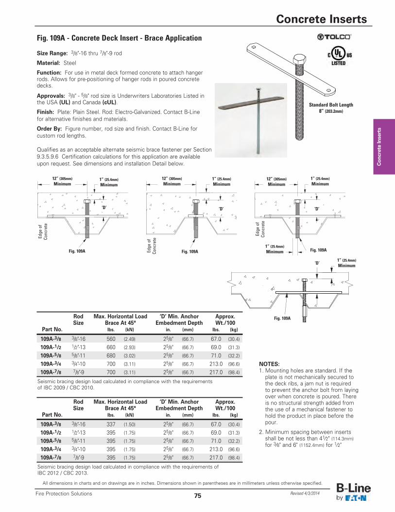
Concrete Inserts
Fig. 109A - Concrete Deck Insert - Brace Application
NOTES:1. Mounting holes are standard. If the plate is not mechanically secured to the deck ribs, a jam nut is required to prevent the anchor bolt from laying over when concrete is poured. There is no structural strength added from the use of a mechanical fastener to hold the product in place before the pour.
2. Minimum spacing between inserts shall be not less than 41⁄2" (114.3mm)for 3⁄8" and 6" (1152.4mm) for 1⁄2"
Seismic bracing design load calculated in compliance with the requirements ofIBC 2012 / CBC 2013.
Rod Max. Horizontal Load ‘D’ Min. Anchor Approx.Size Brace At 45° Embedment Depth Wt./100
Part No. lbs. (kN) in. (mm) lbs. (kg)
109A-3/8 3/8"-16 337 (1.50) 25/8" (66.7) 67.0 (30.4)
109A-1/2 1/2"-13 395 (1.75) 25/8" (66.7) 69.0 (31.3)
109A-5/8 5/8"-11 395 (1.75) 25/8" (66.7) 71.0 (32.2)
109A-3/4 3/4"-10 395 (1.75) 25/8" (66.7) 213.0 (96.6)
109A-7/8 7/8"-9 395 (1.75) 25/8" (66.7) 217.0 (98.4)
Size Range: 3/8"-16 thru 7/8"-9 rod
Material: Steel
Function: For use in metal deck formed concrete to attach hangerrods. Allows for pre-positioning of hanger rods in poured concretedecks.
Approvals: 3/8" - 5/8" rod size is Underwriters Laboratories Listed inthe USA (UL) and Canada (cUL).
Finish: Plate: Plain Steel. Rod: Electro-Galvanized. Contact B-Linefor alternative finishes and materials.
Order By: Figure number, rod size and finish. Contact B-Line forcustom rod lengths.
Qualifies as an acceptable alternate seismic brace fastener per Section9.3.5.9.6 Certification calculations for this application are availableupon request. See dimensions and installation Detail below.
12” (305mm)Minimum
‘D’ ‘D’ ‘D’
Edge
of
Conc
rete
Edge
of
Conc
rete
Edge
of
Conc
rete
Fig. 109A Fig. 109AFig. 109A
12” (305mm)Minimum
1” (25.4mm)Minimum
1” (25.4mm)Minimum
1” (25.4mm)Minimum
1” (25.4mm)Minimum
12” (305mm)Minimum
Standard Bolt Length8” (203.2mm)
1î
A
Fig. 109A
‘D’1” (25.4mm)Minimum
All dimensions in charts and on drawings are in inches. Dimensions shown in parentheses are in millimeters unless otherwise specified.
Concrete Inserts
75Fire Protection Solutions Revised 4/3/2014
Seismic bracing design load calculated in compliance with the requirementsof IBC 2009 / CBC 2010.
Rod Max. Horizontal Load ‘D’ Min. Anchor Approx.Size Brace At 45° Embedment Depth Wt./100
Part No. lbs. (kN) in. (mm) lbs. (kg)
109A-3/8 3/8"-16 560 (2.49) 25/8" (66.7) 67.0 (30.4)
109A-1/2 1/2"-13 660 (2.93) 25/8" (66.7) 69.0 (31.3)
109A-5/8 5/8"-11 680 (3.02) 25/8" (66.7) 71.0 (32.2)
109A-3/4 3/4"-10 700 (3.11) 25/8" (66.7) 213.0 (96.6)
109A-7/8 7/8"-9 700 (3.11) 25/8" (66.7) 217.0 (98.4)
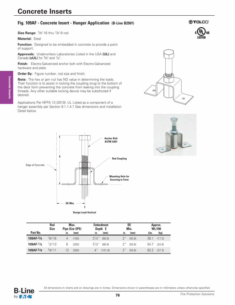
Concrete Inserts
Fig. 109AF - Concrete Insert - Hanger Application (B-Line B2501)
Rod Max. Embedment DE Approx.Size Pipe Size (IPS) Depth E Min. Wt./100
Part No. in. (mm) in. (mm) in. (mm) Lbs. (kg)
109AF-3/8 3/8"-16 4 (100) 31/2” (88.9) 2” (50.8) 38.1 (17.3)
109AF-1/2 1/2"-13 8 (200) 31/2” (88.9) 2” (50.8) 54.7 (24.8)
109AF-5/8 5/8"-11 12 (300) 4” (101.6) 2” (50.8) 82.2 (37.3)
Size Range: 3/8"-16 thru 7/8"-9 rod
Material: Steel
Function: Designed to be embedded in concrete to provide a pointof support.
Approvals: Underwriters Laboratories Listed in the USA (UL) andCanada (cUL) for 3/8" and 1/2".
Finish: Electro-Galvanized anchor bolt with Electro-Galvanizedhardware and plate.
Order By: Figure number, rod size and finish.
Note: The hex or jam nut has NO value in determining the loads.Their function is to assist in locking the coupling snug to the bottom ofthe deck form preventing the concrete from leaking into the couplingthreads. Any other suitable locking device may be substituted ifdesired.
Applications Per NFPA 13 (2010): UL Listed as a component of ahanger assembly per Section 9.1.1.4.1 See dimensions and installationDetail below.
Rod Coupling
Design Load-Vertical
Edge of Concrete
Anchor BoltASTM A307
DE Min.
E
Mounting Hole forSecuring to Form
All dimensions in charts and on drawings are in inches. Dimensions shown in parentheses are in millimeters unless otherwise specified.
Concrete Inserts
Fire Protection Solutions76
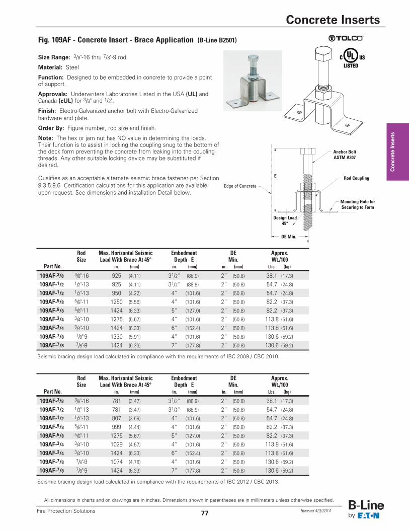
Concrete Inserts
Fig. 109AF - Concrete Insert - Brace Application (B-Line B2501)
Rod Max. Horizontal Seismic Embedment DE Approx.Size Load With Brace At 45° Depth E Min. Wt./100
Part No. in. (mm) in. (mm) in. (mm) Lbs. (kg)
109AF-3/8 3/8"-16 925 (4.11) 31/2” (88.9) 2” (50.8) 38.1 (17.3)
109AF-1/2 1/2"-13 925 (4.11) 31/2” (88.9) 2” (50.8) 54.7 (24.8)
109AF-1/2 1/2"-13 950 (4.22) 4” (101.6) 2” (50.8) 54.7 (24.8)
109AF-5/8 5/8"-11 1250 (5.56) 4” (101.6) 2” (50.8) 82.2 (37.3)
109AF-5/8 5/8"-11 1424 (6.33) 5” (127.0) 2” (50.8) 82.2 (37.3)
109AF-3/4 3/4"-10 1275 (5.67) 4” (101.6) 2” (50.8) 113.8 (51.6)109AF-3/4 3/4"-10 1424 (6.33) 6” (152.4) 2” (50.8) 113.8 (51.6)109AF-7/8 7/8"-9 1330 (5.91) 4” (101.6) 2” (50.8) 130.6 (59.2)109AF-7/8 7/8"-9 1424 (6.33) 7” (177.8) 2” (50.8) 130.6 (59.2)
Size Range: 3/8"-16 thru 7/8"-9 rod
Material: Steel
Function: Designed to be embedded in concrete to provide a pointof support.
Approvals: Underwriters Laboratories Listed in the USA (UL) andCanada (cUL) for 3/8" and 1/2".
Finish: Electro-Galvanized anchor bolt with Electro-Galvanizedhardware and plate.
Order By: Figure number, rod size and finish.
Note: The hex or jam nut has NO value in determining the loads.Their function is to assist in locking the coupling snug to the bottom ofthe deck form preventing the concrete from leaking into the couplingthreads. Any other suitable locking device may be substituted ifdesired.
Qualifies as an acceptable alternate seismic brace fastener per Section9.3.5.9.6 Certification calculations for this application are availableupon request. See dimensions and installation Detail below.
Rod Coupling
Design Load45°
Edge of Concrete
Anchor BoltASTM A307
DE Min.
E
Mounting Hole forSecuring to Form
Seismic bracing design load calculated in compliance with the requirements of IBC 2009 / CBC 2010.
Rod Max. Horizontal Seismic Embedment DE Approx.Size Load With Brace At 45° Depth E Min. Wt./100
Part No. in. (mm) in. (mm) in. (mm) Lbs. (kg)
109AF-3/8 3/8"-16 781 (3.47) 31/2” (88.9) 2” (50.8) 38.1 (17.3)
109AF-1/2 1/2"-13 781 (3.47) 31/2” (88.9) 2” (50.8) 54.7 (24.8)
109AF-1/2 1/2"-13 807 (3.59) 4” (101.6) 2” (50.8) 54.7 (24.8)
109AF-5/8 5/8"-11 999 (4.44) 4” (101.6) 2” (50.8) 82.2 (37.3)
109AF-5/8 5/8"-11 1275 (5.67) 5” (127.0) 2” (50.8) 82.2 (37.3)
109AF-3/4 3/4"-10 1029 (4.57) 4” (101.6) 2” (50.8) 113.8 (51.6)109AF-3/4 3/4"-10 1424 (6.33) 6” (152.4) 2” (50.8) 113.8 (51.6)109AF-7/8 7/8"-9 1074 (4.78) 4” (101.6) 2” (50.8) 130.6 (59.2)109AF-7/8 7/8"-9 1424 (6.33) 7” (177.8) 2” (50.8) 130.6 (59.2)
Seismic bracing design load calculated in compliance with the requirements of IBC 2012 / CBC 2013.
All dimensions in charts and on drawings are in inches. Dimensions shown in parentheses are in millimeters unless otherwise specified.
Concrete Inserts
77Fire Protection Solutions Revised 4/3/2014
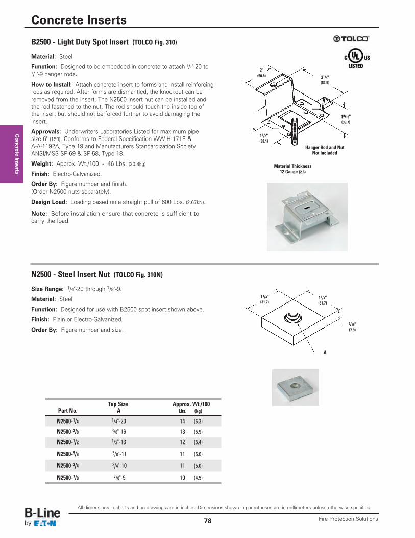
Concrete Inserts
B2500 - Light Duty Spot Insert (TOLCO Fig. 310)
N2500 - Steel Insert Nut (TOLCO Fig. 310N)
A
31/4"(82.5)
19/16"(39.7)
11/2"(38.1)
11/4"(31.7)
11/4"(31.7)
5/16"(7.9)
Hanger Rod and NutNot Included
Material Thickness12 Gauge (2.6)
2"(50.8)
Tap Size Approx. Wt./100Part No. A Lbs. (kg)
N2500-1/4 1/4"-20 14 (6.3)
N2500-3/8 3/8"-16 13 (5.9)
N2500-1/2 1/2"-13 12 (5.4)
N2500-5/8 5/8"-11 11 (5.0)
N2500-3/4 3/4"-10 11 (5.0)
N2500-7/8 7/8"-9 10 (4.5)
Material: Steel
Function: Designed to be embedded in concrete to attach 1/4"-20 to7/8"-9 hanger rods.
How to Install: Attach concrete insert to forms and install reinforcingrods as required. After forms are dismantled, the knockout can beremoved from the insert. The N2500 insert nut can be installed andthe rod fastened to the nut. The rod should touch the inside top ofthe insert but should not be forced further to avoid damaging theinsert.
Approvals: Underwriters Laboratories Listed for maximum pipesize 6" (150). Conforms to Federal Specification WW-H-171E &A-A-1192A, Type 19 and Manufacturers Standardization SocietyANSI/MSS SP-69 & SP-58, Type 18.
Weight: Approx. Wt./100 - 46 Lbs. (20.8kg)
Finish: Electro-Galvanized.
Order By: Figure number and finish.(Order N2500 nuts separately).
Design Load: Loading based on a straight pull of 600 Lbs. (2.67kN).
Note: Before installation ensure that concrete is sufficient tocarry the load.
Size Range: 1/4"-20 through 7/8"-9.
Material: Steel
Function: Designed for use with B2500 spot insert shown above.
Finish: Plain or Electro-Galvanized.
Order By: Figure number and size.
All dimensions in charts and on drawings are in inches. Dimensions shown in parentheses are in millimeters unless otherwise specified.
Concrete Inserts
Fire Protection Solutions78
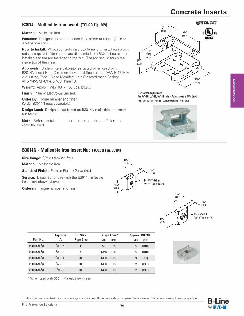
Concrete Inserts
B3014N - Malleable Iron Insert Nut (TOLCO Fig. 309N)
Horizontal Adjustment:For 3/8"-16, 1/2"-13, 5/8"-11 rods - Adjustment is 13/4" (44.4)
For 3/4"-10, 7/8"-9 rods - Adjustment is 13/16" (30.2)
2"(50.8)
33/8"(85.7)
17/8"(47.6)
11/4"(31.7)
1/2"(12.7)
1/2"(12.7)
17/8"(47.6)
15/8"(41.3)
31/4"(82.5)
21/4"(57.1)
13/16"(20.6)
For 3/4"-10 &7/8"-9 Tap Size 'A'
For 3/8"-16 thru5/8"-11 Tap Sizes 'A'
Tap Size UL Max. Design Load* Approx. Wt./100Part No. 'A' Pipe Size Lbs. (kN) Lbs. (kg)
B3014N-3/8 3/8"-16 4” 730 (3.25) 22 (10.0)
B3014N-1/2 1/2"-13 8” 1350 (6.00) 22 (10.0)
B3014N-5/8 5/8"-11 10” 1400 (6.23) 20 (9.1)
B3014N-3/4 3/4"-10 10” 1400 (6.23) 29 (13.1)
B3014N-7/8 7/8"-9 10” 1400 (6.23) 29 (13.1)
* When used with B3014 Malleable Iron Insert.
Size Range: 3/8"-20 through 7/8"-9.
Material: Malleable Iron
Standard Finish: Plain or Electro-Galvanized
Service: Designed for use with the B3014 malleableiron insert shown above.
Ordering: Figure number and finish.
Material: Malleable Iron
Function: Designed to be embedded in concrete to attach 3/8"-16 to7/8"-9 hanger rods.
How to Install: Attach concrete insert to forms and install reinforcingrods as required. After forms are dismantled, the B3014N nut can beinstalled and the rod fastened to the nut. The rod should touch theinside top of the insert.
Approvals: Underwriters Laboratories Listed when used withB3014N Insert Nut. Conforms to Federal Specification WW-H-171E &A-A-1192A, Type 18 and Manufacturers Standardization SocietyANSI/MSS SP-69 & SP-58, Type 18.
Weight: Approx. Wt./100 - 166 Lbs. (75.3kg)
Finish: Plain or Electro-Galvanized.
Order By: Figure number and finish.(Order B3014N nuts separately).
Design Load: Design Loads based on B3014N malleable iron insertnut below.
Note: Before installation ensure that concrete is sufficient tocarry the load.
B3014 - Malleable Iron Insert (TOLCO Fig. 309)
All dimensions in charts and on drawings are in inches. Dimensions shown in parentheses are in millimeters unless otherwise specified.
Concrete Inserts
79Fire Protection Solutions
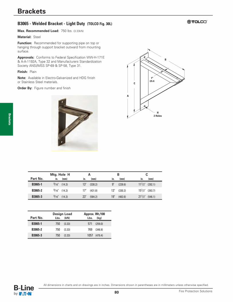
Brackets
B3065 - Welded Bracket - Light Duty (TOLCO Fig. 30L)Max. Recommended Load: 750 lbs. (3.33kN)
Material: Steel
Function: Recommended for supporting pipe on top orhanging through support bracket outward from mountingsurface.
Approvals: Conforms to Federal Specification WW-H-171E& A-A-1192A, Type 32 and Manufacturers StandardizationSociety ANSI/MSS SP-69 & SP-58, Type 31.
Finish: Plain
Note: Available in Electro-Galvanized and HDG finishor Stainless Steel materials.
Order By: Figure number and finish
1" (25.4)
C
A
B
Mtg. Hole H A B CPart No. in. (mm) in. (mm) in. (mm) in. (mm)
B3065-1 9/16" (14.3) 13" (330.2) 9" (228.6) 111/2" (292.1)
B3065-2 9/16" (14.3) 17" (431.8) 13" (330.2) 151/2" (393.7)
B3065-3 9/16" (14.3) 23" (584.2) 19" (482.6) 211/2" (546.1)
Design Load Approx. Wt./100Part No. Lbs. (kN) Lbs. (kg)
B3065-1 750 (3.33) 571 (259.0)
B3065-2 750 (3.33) 769 (348.8)
B3065-3 750 (3.33) 1057 (479.4)
H2 Holes
All dimensions in charts and on drawings are in inches. Dimensions shown in parentheses are in millimeters unless otherwise specified.
Brackets
Fire Protection Solutions80
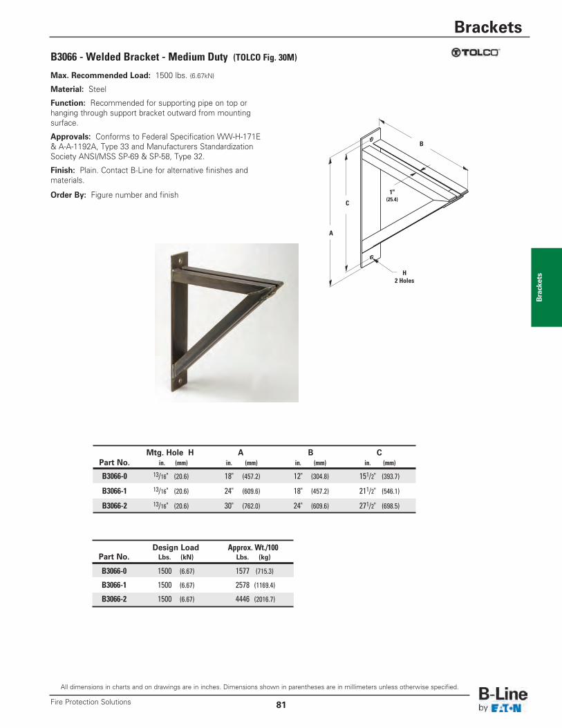
Brackets
B3066 - Welded Bracket - Medium Duty (TOLCO Fig. 30M)
Max. Recommended Load: 1500 lbs. (6.67kN)
Material: Steel
Function: Recommended for supporting pipe on top orhanging through support bracket outward from mountingsurface.
Approvals: Conforms to Federal Specification WW-H-171E& A-A-1192A, Type 33 and Manufacturers StandardizationSociety ANSI/MSS SP-69 & SP-58, Type 32.
Finish: Plain. Contact B-Line for alternative finishes andmaterials.
Order By: Figure number and finish
B
C
A
H2 Holes
1" (25.4)
All dimensions in charts and on drawings are in inches. Dimensions shown in parentheses are in millimeters unless otherwise specified.
Brackets
81Fire Protection Solutions
Mtg. Hole H A B CPart No. in. (mm) in. (mm) in. (mm) in. (mm)
B3066-0 13/16" (20.6) 18" (457.2) 12" (304.8) 151/2" (393.7)
B3066-1 13/16" (20.6) 24" (609.6) 18" (457.2) 211/2" (546.1)
B3066-2 13/16" (20.6) 30" (762.0) 24" (609.6) 271/2" (698.5)
Design Load Approx. Wt./100Part No. Lbs. (kN) Lbs. (kg)
B3066-0 1500 (6.67) 1577 (715.3)
B3066-1 1500 (6.67) 2578 (1169.4)
B3066-2 1500 (6.67) 4446 (2016.7)
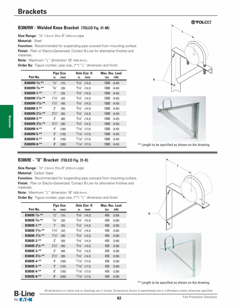
Brackets
B3069W - Welded Knee Bracket (TOLCO Fig. 31-M)
Size Range: 1/2" (15mm) thru 8" (200mm) pipeMaterial: SteelFunction: Recommended for suspending pipe outward from mounting surface.Finish: Plain or Electro-Galvanized. Contact B-Line for alternative finishes andmaterials.Note: Maximum “L” dimension 16" (406.4mm).Order By: Figure number, pipe size, (**) “L” dimension and finish
Pipe Size Hole Size H Max. Rec. LoadPart No. in. (mm) in. (mm) Lbs. (kN)
B3069W-1/2-** 1/2" (15) 9/16" (14.3) 1000 (4.45)
B3069W-3/4-** 3/4" (20) 9/16" (14.3) 1000 (4.45)
B3069W-1-** 1" (25) 9/16" (14.3) 1000 (4.45)
B3069W-11/4-** 11/4" (32) 9/16" (14.3) 1000 (4.45)
B3069W-11/2-** 11/2" (40) 9/16" (14.3) 1000 (4.45)
B3069W-2-** 2" (50) 9/16" (14.3) 1000 (4.45)
B3069W-21/2-** 21/2" (65) 9/16" (14.3) 1000 (4.45)
B3069W-3-** 3" (80) 9/16" (14.3) 1000 (4.45)
B3069W-31/2-** 31/2" (90) 9/16" (14.3) 1000 (4.45)
B3069W-4-** 4" (100) 11/16" (17.5) 1000 (4.45)
B3069W-5-** 5" (125) 11/16" (17.5) 1000 (4.45)
B3069W-6-** 6" (150) 11/16" (17.5) 1000 (4.45)
B3069W-8-** 8" (200) 11/16" (17.5) 1000 (4.45)
H
L
B3069E - “O” Bracket (TOLCO Fig. 31-O)
Size Range: 1/2" (15mm) thru 8" (200mm) pipeMaterial: Carbon SteelFunction: Recommended for suspending pipe outward from mounting surface.Finish: Plain or Electro-Galvanized. Contact B-Line for alternative finishes andmaterials.Note: Maximum “L” dimension 16" (406.4mm).Order By: Figure number, pipe size, (**) “L” dimension and finish
Pipe Size Hole Size H Max. Rec. LoadPart No. in. (mm) in. (mm) Lbs. (kN)
B3069E-1/2-** 1/2" (15) 9/16" (14.3) 450 (2.00)
B3069E-3/4-** 3/4" (20) 9/16" (14.3) 450 (2.00)
B3069E-1-** 1" (25) 9/16" (14.3) 450 (2.00)
B3069E-11/4-** 11/4" (32) 9/16" (14.3) 450 (2.00)
B3069E-11/2-** 11/2" (40) 9/16" (14.3) 450 (2.00)
B3069E-2-** 2" (50) 9/16" (14.3) 450 (2.00)
B3069E-21/2-** 21/2" (65) 9/16" (14.3) 450 (2.00)
B3069E-3-** 3" (80) 9/16" (14.3) 450 (2.00)
B3069E-31/2-** 31/2" (90) 9/16" (14.3) 450 (2.00)
B3069E-4-** 4" (100) 11/16" (17.5) 450 (2.00)
B3069E-5-** 5" (125) 11/16" (17.5) 450 (2.00)
B3069E-6-** 6" (150) 11/16" (17.5) 450 (2.00)
B3069E-8-** 8" (200) 11/16" (17.5) 450 (2.00)
H
L
** Length to be specified as shown on the drawing.
** Length to be specified as shown on the drawing.
All dimensions in charts and on drawings are in inches. Dimensions shown in parentheses are in millimeters unless otherwise specified.
Brackets
Fire Protection Solutions82
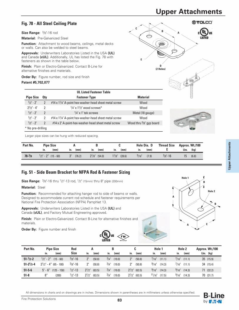
Upper Attachm
entsPart No. Pipe Size A B C Hole Dia. D Thread Size Approx. Wt./100
in. (mm) in. (mm) in. (mm) in. (mm) in. (mm) E Lbs. (kg)
78-3/8 1/2" - 2” (15 - 60) 3" (76.2) 21/8" (54.0) 11/8" (28.6) 5/16" (7.9) 3/8"-16 15 (6.8)
Size Range: 3/8"-16 rod
Material: Pre-Galvanized Steel
Function: Attachment to wood beams, ceilings, metal decksor walls. Can also be welded to steel beams.
Approvals: Underwriters Laboratories Listed in the USA (UL)and Canada (cUL). Additionally, UL has listed the Fig. 78 withfasteners as shown in the table below.
Finish: Plain or Electro-Galvanized. Contact B-Line foralternative finishes and materials.
Order By: Figure number, rod size and finish
Patent #5,702,077
UL Listed Fastener TablePipe Size Qty Fastener Type Material1/2" - 2" 2 #14 x 11/4" A-point hex-washer-head sheet metal screw Wood21/2" - 4" 2 1/4" x 11/2" wood screws* Wood1/2" - 2" 2 1/4" x 1" tek screws Metal (18 gauge)1/2" - 2" 2 #14 x 11/4" A-point hex-washer-head sheet metal screw Wood1/2" - 2" 2 #14 x 2" A-point-hex-washer-head sheet metal screw Wood thru 5/8" gyp board
* No pre-drilling
Fig. 78 - All Steel Ceiling Plate
ABC
D(2 Holes)
E
Fig. 51 - Side Beam Bracket for NFPA Rod & Fastener Sizing
Size Range: 3/8"-16 thru 1/2"-13 rod, 1/2" (15mm) thru 8" pipe (200mm)
Material: Steel
Function: Recommended for attaching hanger rod to side of beams or walls.Designed to accommodate current rod schedule and fastener requirements perNational Fire Protection Association (NFPA) Pamphlet 13.
Approvals: Underwriters Laboratories Listed in the USA (UL) andCanada (cUL), and Factory Mutual Engineering approved.
Finish: Plain or Electro-Galvanized. Contact B-Line for alternative finishes andmaterials.
Order By: Figure number and finish
Part No. Pipe Size Rod A B C Hole 1 Hole 2 Approx. Wt./100in. (mm) Size in. (mm) in. (mm) in. (mm) in. (mm) in. (mm) Lbs. (kg)
51-1/2-2 1/2" - 2” (15 - 60) 3/8"-16 2" (50.8) 3/4" (19.0) 2" (50.8) 7/16" (11.1) 7/16" (11.1) 35 (15.9)
51-21/2-4 21/2" - 4” (65 - 100) 3/8"-16 2" (50.8) 3/4" (19.0) 2" (50.8) 9/16" (14.3) 7/16" (11.1) 34 (15.4)
51-5-6 5" - 6” (125 - 150) 1/2"-13 21/2" (63.5) 3/4" (19.0) 21/2" (63.5) 9/16" (14.3) 9/16" (14.3) 71 (32.2)
51-8 8” (200) 1/2"-13 21/2" (63.5) 3/4" (19.0) 21/2" (63.5) 11/16" (17.5) 9/16" (14.3) 70 (31.7)
Hole 1
Hole 2
B
B
C
A
A
Larger pipe sizes can be hung with reduced spacing.
All dimensions in charts and on drawings are in inches. Dimensions shown in parentheses are in millimeters unless otherwise specified.
Upper Attachments
83Fire Protection Solutions
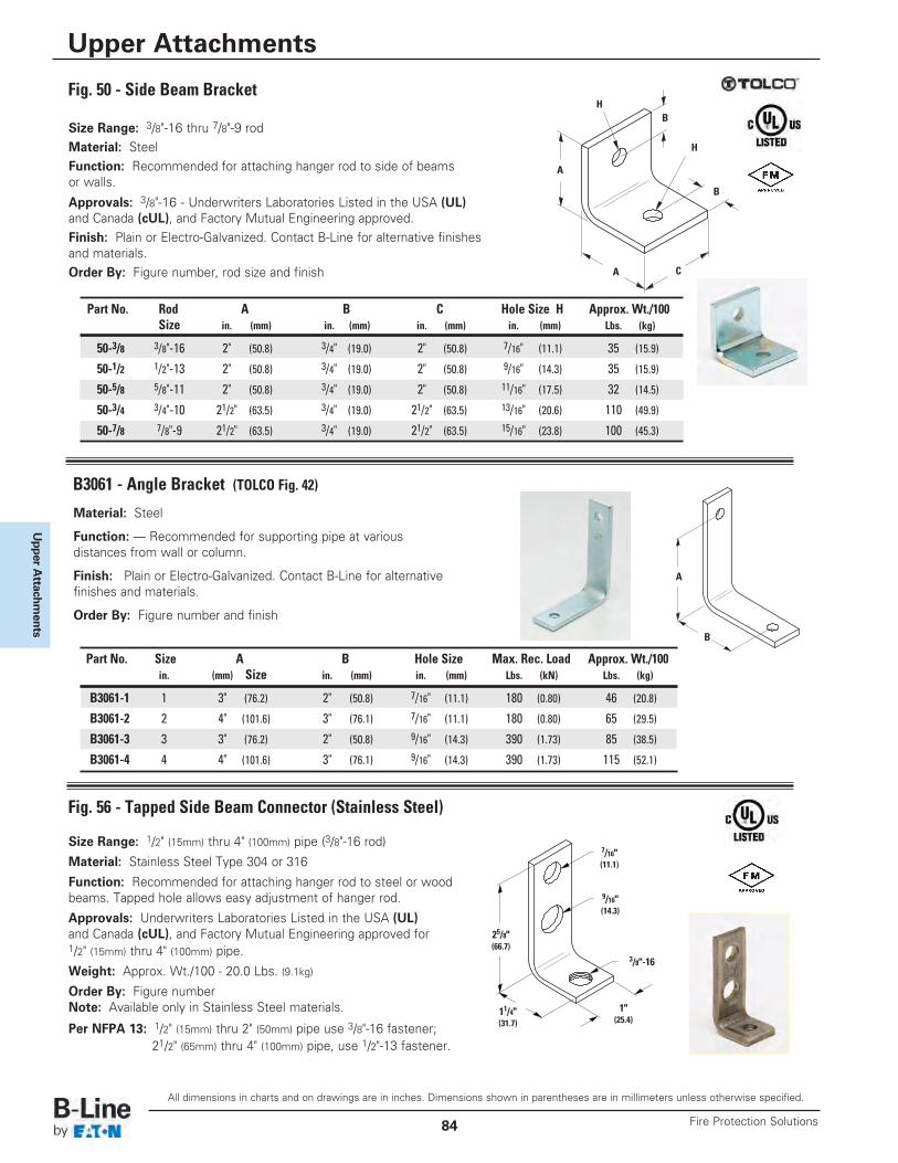
Upper A
ttachments
Size Range: 3/8"-16 thru 7/8"-9 rodMaterial: SteelFunction: Recommended for attaching hanger rod to side of beamsor walls.
Approvals: 3/8"-16 - Underwriters Laboratories Listed in the USA (UL)and Canada (cUL), and Factory Mutual Engineering approved.Finish: Plain or Electro-Galvanized. Contact B-Line for alternative finishesand materials.Order By: Figure number, rod size and finish
Size Range: 1/2" (15mm) thru 4" (100mm) pipe (3/8"-16 rod)
Material: Stainless Steel Type 304 or 316
Function: Recommended for attaching hanger rod to steel or woodbeams. Tapped hole allows easy adjustment of hanger rod.
Approvals: Underwriters Laboratories Listed in the USA (UL)and Canada (cUL), and Factory Mutual Engineering approved for1/2" (15mm) thru 4" (100mm) pipe.
Weight: Approx. Wt./100 - 20.0 Lbs. (9.1kg)
Order By: Figure numberNote: Available only in Stainless Steel materials.
Per NFPA 13: 1/2" (15mm) thru 2" (50mm) pipe use 3/8"-16 fastener;21/2" (65mm) thru 4" (100mm) pipe, use 1/2"-13 fastener.
Fig. 50 - Side Beam Bracket
Fig. 56 - Tapped Side Beam Connector (Stainless Steel)
C
A
A
BH
H
B
3/8"-16
25/8"(66.7)
1"(25.4)
11/4"(31.7)
7/16"(11.1)
9/16"(14.3)
Part No. Rod A B C Hole Size H Approx. Wt./100Size in. (mm) in. (mm) in. (mm) in. (mm) Lbs. (kg)
50-3/8 3/8"-16 2" (50.8) 3/4" (19.0) 2" (50.8) 7/16" (11.1) 35 (15.9)
50-1/2 1/2"-13 2" (50.8) 3/4" (19.0) 2" (50.8) 9/16" (14.3) 35 (15.9)
50-5/8 5/8"-11 2" (50.8) 3/4" (19.0) 2" (50.8) 11/16" (17.5) 32 (14.5)
50-3/4 3/4"-10 21/2" (63.5) 3/4" (19.0) 21/2" (63.5) 13/16" (20.6) 110 (49.9)
50-7/8 7/8"-9 21/2" (63.5) 3/4" (19.0) 21/2" (63.5) 15/16" (23.8) 100 (45.3)
Material: Steel
Function: — Recommended for supporting pipe at variousdistances from wall or column.
Finish: Plain or Electro-Galvanized. Contact B-Line for alternativefinishes and materials.
Order By: Figure number and finish
B3061 - Angle Bracket (TOLCO Fig. 42)
A
B
Part No. Size A B Hole Size Max. Rec. Load Approx. Wt./100in. (mm) Size in. (mm) in. (mm) Lbs. (kN) Lbs. (kg)
B3061-1 1 3" (76.2) 2" (50.8) 7/16" (11.1) 180 (0.80) 46 (20.8)
B3061-2 2 4" (101.6) 3" (76.1) 7/16" (11.1) 180 (0.80) 65 (29.5)
B3061-3 3 3" (76.2) 2" (50.8) 9/16" (14.3) 390 (1.73) 85 (38.5)
B3061-4 4 4" (101.6) 3" (76.1) 9/16" (14.3) 390 (1.73) 115 (52.1)
All dimensions in charts and on drawings are in inches. Dimensions shown in parentheses are in millimeters unless otherwise specified.
Upper Attachments
Fire Protection Solutions84
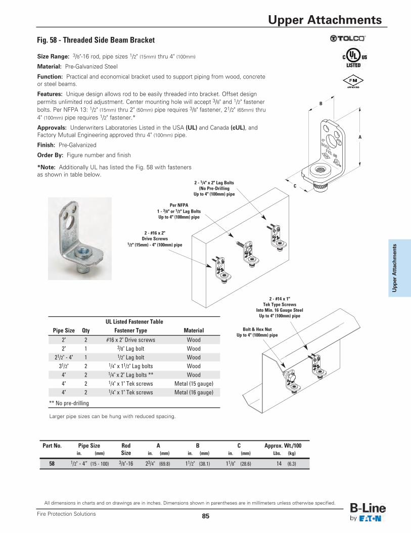
Upper Attachm
ents
Size Range: 3/8"-16 rod, pipe sizes 1/2" (15mm) thru 4" (100mm)
Material: Pre-Galvanized Steel
Function: Practical and economical bracket used to support piping from wood, concreteor steel beams.
Features: Unique design allows rod to be easily threaded into bracket. Offset designpermits unlimited rod adjustment. Center mounting hole will accept 3/8" and 1/2" fastenerbolts. Per NFPA 13: 1/2" (15mm) thru 2" (50mm) pipe requires 3/8" fastener, 21/2" (65mm) thru4" (100mm) pipe requires 1/2" fastener.*
Approvals: Underwriters Laboratories Listed in the USA (UL) and Canada (cUL), andFactory Mutual Engineering approved thru 4" (100mm) pipe.
Finish: Pre-Galvanized
Order By: Figure number and finish
*Note: Additionally UL has listed the Fig. 58 with fastenersas shown in table below.
Fig. 58 - Threaded Side Beam Bracket
A
C2 - 1/4" x 2" Lag Bolts
(No Pre-DrillingUp to 4" (100mm) pipe
Per NFPA1 - 3/8" or 1/2" Lag BoltsUp to 4" (100mm) pipe
2 - #16 x 2"Drive Screws
1/2" (15mm) - 4" (100mm) pipe
Bolt & Hex NutUp to 4" (100mm) pipe
2 - #14 x 1"Tek Type Screws
Into Min. 16 Gauge SteelUp to 4" (100mm) pipe
B
UL Listed Fastener TablePipe Size Qty Fastener Type Material
2" 2 #16 x 2" Drive screws Wood2" 1 3/8" Lag bolt Wood
21/2" - 4" 1 1/2" Lag bolt Wood31/2" 2 1/4" x 11/2" Lag bolts Wood4" 2 1/4" x 2" Lag bolts ** Wood4" 2 1/4" x 1" Tek screws Metal (15 gauge)4" 2 1/4" x 1" Tek screws Metal (16 gauge)
** No pre-drilling
Part No. Pipe Size Rod A B C Approx. Wt./100in. (mm) Size in. (mm) in. (mm) in. (mm) Lbs. (kg)
58 1/2" - 4” (15 - 100) 3/8"-16 23/4" (69.8) 11/2" (38.1) 11/8" (28.6) 14 (6.3)
Larger pipe sizes can be hung with reduced spacing.
All dimensions in charts and on drawings are in inches. Dimensions shown in parentheses are in millimeters unless otherwise specified.
Upper Attachments
85Fire Protection Solutions
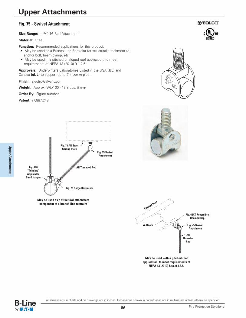
Upper A
ttachments
Size Range: — 3/8"-16 Rod Attachment
Material: Steel
Function: Recommended applications for this product: • May be used as a Branch Line Restraint for structural attachment to
anchor bolt, beam clamp, etc. • May be used in a pitched or sloped roof application, to meet
requirements of NFPA 13 (2010) 9.1.2.6.
Approvals: Underwriters Laboratories Listed in the USA (UL) and Canada (cUL) to support up to 4" (100mm) pipe.
Finish: Electro-Galvanized
Weight: Approx. Wt./100 - 13.3 Lbs. (6.0kg)
Order By: Figure number
Patent: #7,887,248
Fig. 75 - Swivel Attachment
Fig. 78 All SteelCeiling Plate
Fig. 75 SwivelAttachment
Fig. 75 SwivelAttachment
All Threaded Rod
AllThreaded
Rod
W-Beam
Pitched
Roof
Fig. 25 Surge Restrainer
Fig. 200“Trimline”Adjustable
Band Hanger
May be used as a structural attachmentcomponent of a branch line restraint
May be used with a pitched roofapplication, to meet requirements of
NFPA 13 (2010) Sec. 9.1.2.5.
Fig. 65XT ReversibleBeam Clamp
All dimensions in charts and on drawings are in inches. Dimensions shown in parentheses are in millimeters unless otherwise specified.
Upper Attachments
Fire Protection Solutions86
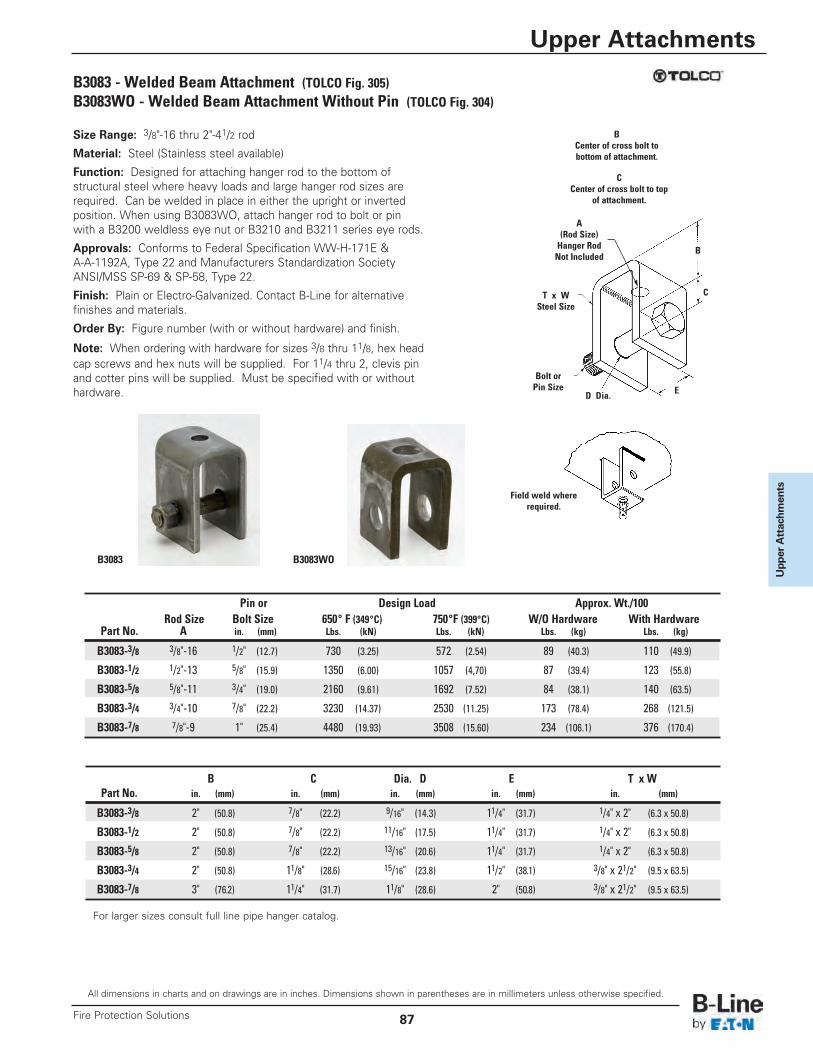
Upper Attachm
ents
Size Range: 3/8"-16 thru 2"-41/2 rod
Material: Steel (Stainless steel available)
Function: Designed for attaching hanger rod to the bottom ofstructural steel where heavy loads and large hanger rod sizes arerequired. Can be welded in place in either the upright or invertedposition. When using B3083WO, attach hanger rod to bolt or pinwith a B3200 weldless eye nut or B3210 and B3211 series eye rods.
Approvals: Conforms to Federal Specification WW-H-171E &A-A-1192A, Type 22 and Manufacturers Standardization SocietyANSI/MSS SP-69 & SP-58, Type 22.
Finish: Plain or Electro-Galvanized. Contact B-Line for alternativefinishes and materials.
Order By: Figure number (with or without hardware) and finish.
Note: When ordering with hardware for sizes 3/8 thru 11/8, hex headcap screws and hex nuts will be supplied. For 11/4 thru 2, clevis pinand cotter pins will be supplied. Must be specified with or withouthardware.
B3083 - Welded Beam Attachment (TOLCO Fig. 305)B3083WO - Welded Beam Attachment Without Pin (TOLCO Fig. 304)
D Dia.
T x WSteel Size
A(Rod Size)Hanger RodNot Included
BCenter of cross bolt tobottom of attachment.
CCenter of cross bolt to top
of attachment.
C
B
Bolt orPin Size E
Pin or Design Load Approx. Wt./100Rod Size Bolt Size 650° F (349°C) 750°F (399°C) W/O Hardware With Hardware
Part No. A in. (mm) Lbs. (kN) Lbs. (kN) Lbs. (kg) Lbs. (kg)
B3083-3/8 3/8"-16 1/2" (12.7) 730 (3.25) 572 (2.54) 89 (40.3) 110 (49.9)
B3083-1/2 1/2"-13 5/8" (15.9) 1350 (6.00) 1057 (4,70) 87 (39.4) 123 (55.8)
B3083-5/8 5/8"-11 3/4" (19.0) 2160 (9.61) 1692 (7.52) 84 (38.1) 140 (63.5)
B3083-3/4 3/4"-10 7/8" (22.2) 3230 (14.37) 2530 (11.25) 173 (78.4) 268 (121.5)
B3083-7/8 7/8"-9 1" (25.4) 4480 (19.93) 3508 (15.60) 234 (106.1) 376 (170.4)
B C Dia. D E T x WPart No. in. (mm) in. (mm) in. (mm) in. (mm) in. (mm)
B3083-3/8 2" (50.8) 7/8" (22.2) 9/16" (14.3) 11/4" (31.7) 1/4" x 2" (6.3 x 50.8)
B3083-1/2 2" (50.8) 7/8" (22.2) 11/16" (17.5) 11/4" (31.7) 1/4" x 2" (6.3 x 50.8)
B3083-5/8 2" (50.8) 7/8" (22.2) 13/16" (20.6) 11/4" (31.7) 1/4" x 2" (6.3 x 50.8)
B3083-3/4 2" (50.8) 11/8" (28.6) 15/16" (23.8) 11/2" (38.1) 3/8" x 21/2" (9.5 x 63.5)
B3083-7/8 3" (76.2) 11/4" (31.7) 11/8" (28.6) 2" (50.8) 3/8" x 21/2" (9.5 x 63.5)
Field weld whererequired.
B3083 B3083WO
For larger sizes consult full line pipe hanger catalog.
All dimensions in charts and on drawings are in inches. Dimensions shown in parentheses are in millimeters unless otherwise specified.
Upper Attachments
87Fire Protection Solutions
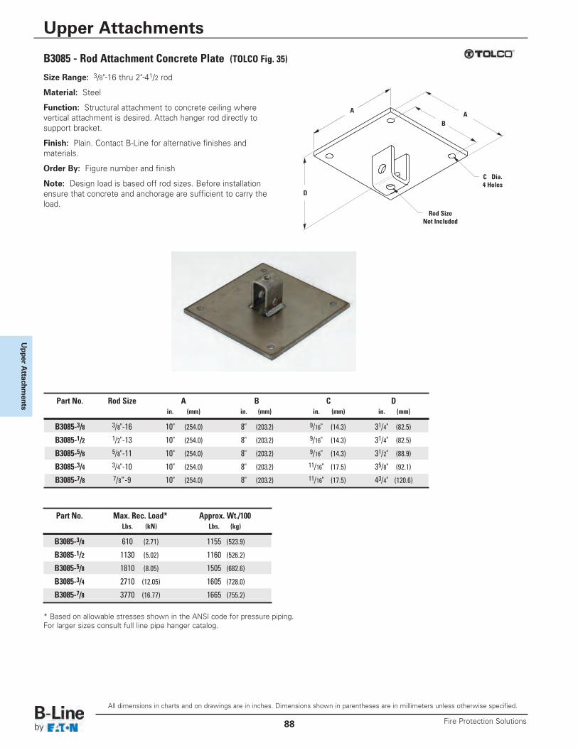
Upper A
ttachments
Size Range: 3/8"-16 thru 2"-41/2 rod
Material: Steel
Function: Structural attachment to concrete ceiling wherevertical attachment is desired. Attach hanger rod directly tosupport bracket.
Finish: Plain. Contact B-Line for alternative finishes andmaterials.
Order By: Figure number and finish
Note: Design load is based off rod sizes. Before installationensure that concrete and anchorage are sufficient to carry theload.
Rod SizeNot Included
A A
D
C Dia.4 Holes
B
Part No. Rod Size A B C Din. (mm) in. (mm) in. (mm) in. (mm)
B3085-3/8 3/8"-16 10" (254.0) 8" (203.2) 9/16" (14.3) 31/4" (82.5)
B3085-1/2 1/2"-13 10" (254.0) 8" (203.2) 9/16" (14.3) 31/4" (82.5)
B3085-5/8 5/8"-11 10" (254.0) 8" (203.2) 9/16" (14.3) 31/2" (88.9)
B3085-3/4 3/4"-10 10" (254.0) 8" (203.2) 11/16" (17.5) 35/8" (92.1)
B3085-7/8 7/8”-9 10" (254.0) 8" (203.2) 11/16" (17.5) 43/4" (120.6)
* Based on allowable stresses shown in the ANSI code for pressure piping.For larger sizes consult full line pipe hanger catalog.
B3085 - Rod Attachment Concrete Plate (TOLCO Fig. 35)
Part No. Max. Rec. Load* Approx. Wt./100Lbs. (kN) Lbs. (kg)
B3085-3/8 610 (2.71) 1155 (523.9)
B3085-1/2 1130 (5.02) 1160 (526.2)
B3085-5/8 1810 (8.05) 1505 (682.6)
B3085-3/4 2710 (12.05) 1605 (728.0)
B3085-7/8 3770 (16.77) 1665 (755.2)
All dimensions in charts and on drawings are in inches. Dimensions shown in parentheses are in millimeters unless otherwise specified.
Upper Attachments
Fire Protection Solutions88
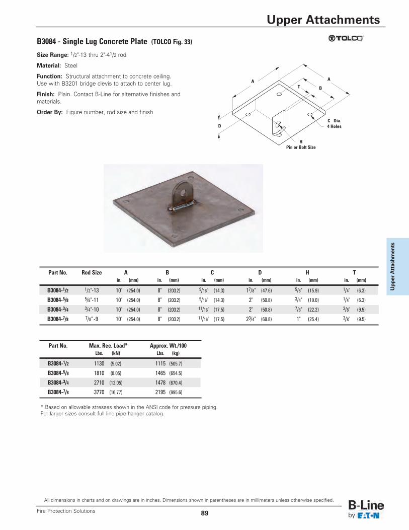
Upper Attachm
ents
B3084 - Single Lug Concrete Plate (TOLCO Fig. 33)
Size Range: 1/2"-13 thru 2"-41/2 rod
Material: Steel
Function: Structural attachment to concrete ceiling.Use with B3201 bridge clevis to attach to center lug.
Finish: Plain. Contact B-Line for alternative finishes andmaterials.
Order By: Figure number, rod size and finish
HPin or Bolt Size
C Dia.4 Holes
A A
D
T B
* Based on allowable stresses shown in the ANSI code for pressure piping.For larger sizes consult full line pipe hanger catalog.
Part No. Max. Rec. Load* Approx. Wt./100Lbs. (kN) Lbs. (kg)
B3084-1/2 1130 (5.02) 1115 (505.7)
B3084-5/8 1810 (8.05) 1465 (654.5)
B3084-3/4 2710 (12.05) 1478 (670.4)
B3084-7/8 3770 (16.77) 2195 (995.6)
Part No. Rod Size A B C D H Tin. (mm) in. (mm) in. (mm) in. (mm) in. (mm) in. (mm)
B3084-1/2 1/2"-13 10" (254.0) 8" (203.2) 9/16" (14.3) 17/8" (47.6) 5/8" (15.9) 1/4" (6.3)
B3084-5/8 5/8"-11 10" (254.0) 8" (203.2) 9/16" (14.3) 2" (50.8) 3/4" (19.0) 1/4" (6.3)
B3084-3/4 3/4"-10 10" (254.0) 8" (203.2) 11/16" (17.5) 2" (50.8) 7/8" (22.2) 3/8" (9.5)
B3084-7/8 7/8”-9 10" (254.0) 8" (203.2) 11/16" (17.5) 23/4" (69.8) 1" (25.4) 3/8" (9.5)
All dimensions in charts and on drawings are in inches. Dimensions shown in parentheses are in millimeters unless otherwise specified.
Upper Attachments
89Fire Protection Solutions
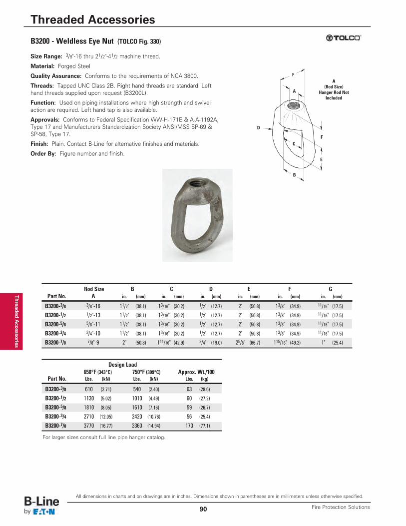
Threaded Accessories
B3200 - Weldless Eye Nut (TOLCO Fig. 330)
Size Range: 3/8"-16 thru 21/2"-41/2 machine thread.
Material: Forged Steel
Quality Assurance: Conforms to the requirements of NCA 3800.
Threads: Tapped UNC Class 2B. Right hand threads are standard. Lefthand threads supplied upon request (B3200L).
Function: Used on piping installations where high strength and swivelaction are required. Left hand tap is also available.
Approvals: Conforms to Federal Specification WW-H-171E & A-A-1192A,Type 17 and Manufacturers Standardization Society ANSI/MSS SP-69 &SP-58, Type 17.
Finish: Plain. Contact B-Line for alternative finishes and materials.
Order By: Figure number and finish.
A(Rod Size)
Hanger Rod NotIncluded
E
F
B
C
F
A
D
Rod Size B C D E F GPart No. A in. (mm) in. (mm) in. (mm) in. (mm) in. (mm) in. (mm)
B3200-3/8 3/8"-16 11/2" (38.1) 13/16" (30.2) 1/2" (12.7) 2" (50.8) 13/8" (34.9) 11/16" (17.5)
B3200-1/2 1/2"-13 11/2" (38.1) 13/16" (30.2) 1/2" (12.7) 2" (50.8) 13/8" (34.9) 11/16" (17.5)
B3200-5/8 5/8"-11 11/2" (38.1) 13/16" (30.2) 1/2" (12.7) 2" (50.8) 13/8" (34.9) 11/16" (17.5)
B3200-3/4 3/4"-10 11/2" (38.1) 13/16" (30.2) 1/2" (12.7) 2" (50.8) 13/8" (34.9) 11/16" (17.5)
B3200-7/8 7/8"-9 2" (50.8) 111/16" (42.9) 3/4" (19.0) 25/8" (66.7) 115/16" (49.2) 1" (25.4)
Design Load650°F (343°C) 750°F (399°C) Approx. Wt./100
Part No. Lbs. (kN) Lbs. (kN) Lbs. (kg)
B3200-3/8 610 (2.71) 540 (2.40) 63 (28.6)
B3200-1/2 1130 (5.02) 1010 (4.49) 60 (27.2)
B3200-5/8 1810 (8.05) 1610 (7.16) 59 (26.7)
B3200-3/4 2710 (12.05) 2420 (10.76) 56 (25.4)
B3200-7/8 3770 (16.77) 3360 (14.94) 170 (77.1)
For larger sizes consult full line pipe hanger catalog.
All dimensions in charts and on drawings are in inches. Dimensions shown in parentheses are in millimeters unless otherwise specified.
Threaded Accessories
Fire Protection Solutions90
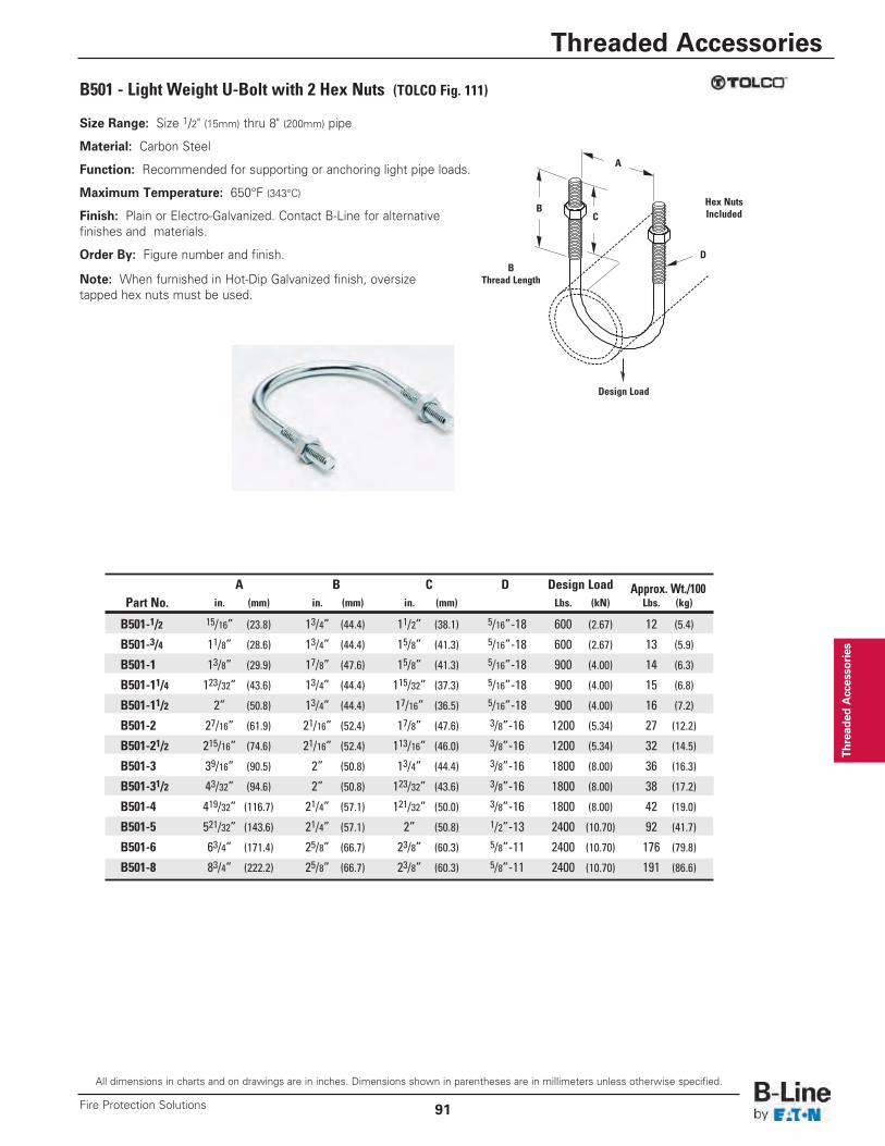
Thread
ed Accesso
ries
B501 - Light Weight U-Bolt with 2 Hex Nuts (TOLCO Fig. 111)
A
B
D
CHex NutsIncluded
Design Load
Size Range: Size 1/2" (15mm) thru 8" (200mm) pipe
Material: Carbon Steel
Function: Recommended for supporting or anchoring light pipe loads.
Maximum Temperature: 650°F (343°C)
Finish: Plain or Electro-Galvanized. Contact B-Line for alternativefinishes and materials.
Order By: Figure number and finish.
Note: When furnished in Hot-Dip Galvanized finish, oversizetapped hex nuts must be used.
A B C D Design Load Approx. Wt./100Part No. in. (mm) in. (mm) in. (mm) Lbs. (kN) Lbs. (kg)
B501-1/2 15/16” (23.8) 13/4” (44.4) 11/2” (38.1) 5/16”-18 600 (2.67) 12 (5.4)
B501-3/4 11/8” (28.6) 13/4” (44.4) 15/8” (41.3) 5/16”-18 600 (2.67) 13 (5.9)
B501-1 13/8” (29.9) 17/8” (47.6) 15/8” (41.3) 5/16”-18 900 (4.00) 14 (6.3)
B501-11/4 123/32” (43.6) 13/4” (44.4) 115/32” (37.3) 5/16”-18 900 (4.00) 15 (6.8)
B501-11/2 2” (50.8) 13/4” (44.4) 17/16” (36.5) 5/16”-18 900 (4.00) 16 (7.2)
B501-2 27/16” (61.9) 21/16” (52.4) 17/8” (47.6) 3/8”-16 1200 (5.34) 27 (12.2)
B501-21/2 215/16” (74.6) 21/16” (52.4) 113/16” (46.0) 3/8”-16 1200 (5.34) 32 (14.5)
B501-3 39/16” (90.5) 2” (50.8) 13/4” (44.4) 3/8”-16 1800 (8.00) 36 (16.3)
B501-31/2 43/32” (94.6) 2” (50.8) 123/32” (43.6) 3/8”-16 1800 (8.00) 38 (17.2)
B501-4 419/32” (116.7) 21/4” (57.1) 121/32” (50.0) 3/8”-16 1800 (8.00) 42 (19.0)
B501-5 521/32” (143.6) 21/4” (57.1) 2” (50.8) 1/2”-13 2400 (10.70) 92 (41.7)
B501-6 63/4” (171.4) 25/8” (66.7) 23/8” (60.3) 5/8”-11 2400 (10.70) 176 (79.8)
B501-8 83/4” (222.2) 25/8” (66.7) 23/8” (60.3) 5/8”-11 2400 (10.70) 191 (86.6)
BThread Length
All dimensions in charts and on drawings are in inches. Dimensions shown in parentheses are in millimeters unless otherwise specified.
Threaded Accessories
91Fire Protection Solutions
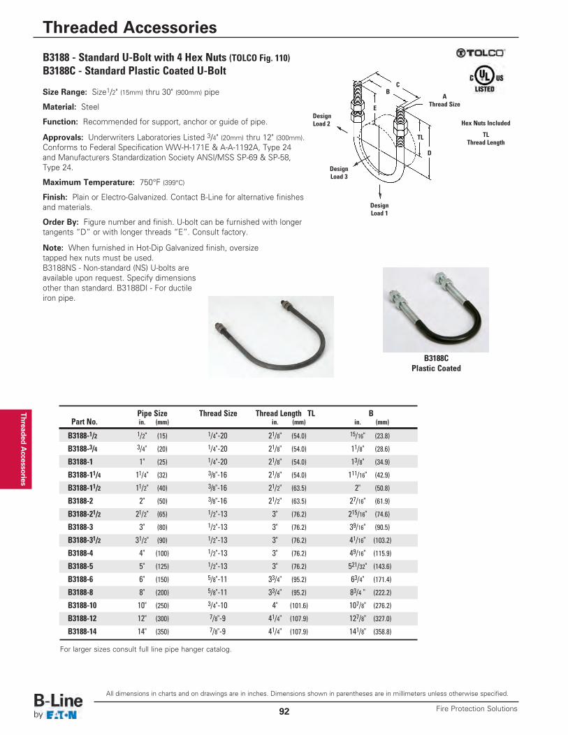
Threaded Accessories
B3188 - Standard U-Bolt with 4 Hex Nuts (TOLCO Fig. 110)B3188C - Standard Plastic Coated U-Bolt
Size Range: Size1/2" (15mm) thru 30" (900mm) pipe
Material: Steel
Function: Recommended for support, anchor or guide of pipe.
Approvals: Underwriters Laboratories Listed 3/4" (20mm) thru 12" (300mm).Conforms to Federal Specification WW-H-171E & A-A-1192A, Type 24and Manufacturers Standardization Society ANSI/MSS SP-69 & SP-58,Type 24.
Maximum Temperature: 750°F (399°C)
Finish: Plain or Electro-Galvanized. Contact B-Line for alternative finishesand materials.
Order By: Figure number and finish. U-bolt can be furnished with longertangents “D” or with longer threads “E”. Consult factory.
Note: When furnished in Hot-Dip Galvanized finish, oversizetapped hex nuts must be used.B3188NS - Non-standard (NS) U-bolts areavailable upon request. Specify dimensionsother than standard. B3188DI - For ductileiron pipe.
TLThread Length
AThread Size
B
E
TL
DesignLoad 2
DesignLoad 3
DesignLoad 1
D
C
Hex Nuts Included
Pipe Size Thread Size Thread Length TL BPart No. in. (mm) in. (mm) in. (mm)
B3188-1/2 1/2" (15) 1/4"-20 21/8" (54.0) 15/16" (23.8)
B3188-3/4 3/4" (20) 1/4"-20 21/8" (54.0) 11/8" (28.6)
B3188-1 1" (25) 1/4"-20 21/8" (54.0) 13/8" (34.9)
B3188-11/4 11/4" (32) 3/8"-16 21/8" (54.0) 111/16" (42.9)
B3188-11/2 11/2" (40) 3/8"-16 21/2" (63.5) 2" (50.8)
B3188-2 2" (50) 3/8"-16 21/2" (63.5) 27/16" (61.9)
B3188-21/2 21/2" (65) 1/2"-13 3" (76.2) 215/16" (74.6)
B3188-3 3" (80) 1/2"-13 3" (76.2) 39/16" (90.5)
B3188-31/2 31/2" (90) 1/2"-13 3" (76.2) 41/16" (103.2)
B3188-4 4" (100) 1/2"-13 3" (76.2) 49/16" (115.9)
B3188-5 5" (125) 1/2"-13 3" (76.2) 521/32" (143.6)
B3188-6 6" (150) 5/8"-11 33/4" (95.2) 63/4" (171.4)
B3188-8 8" (200) 5/8"-11 33/4" (95.2) 83/4 " (222.2)
B3188-10 10" (250) 3/4"-10 4" (101.6) 107/8" (276.2)
B3188-12 12" (300) 7/8"-9 41/4" (107.9) 127/8" (327.0)
B3188-14 14" (350) 7/8"-9 41/4" (107.9) 141/8" (358.8)
B3188CPlastic Coated
For larger sizes consult full line pipe hanger catalog.
All dimensions in charts and on drawings are in inches. Dimensions shown in parentheses are in millimeters unless otherwise specified.
Threaded Accessories
Fire Protection Solutions92
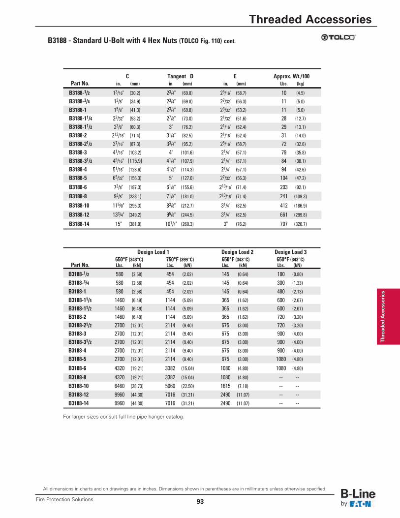
Thread
ed Accesso
ries
C Tangent D E Approx. Wt./100Part No. in. (mm) in. (mm) in. (mm) Lbs. (kg)
B3188-1/2 13/16" (30.2) 23/4" (69.8) 25/16" (58.7) 10 (4.5)
B3188-3/4 13/8" (34.9) 23/4" (69.8) 27/32" (56.3) 11 (5.0)
B3188-1 15/8" (41.3) 23/4" (69.8) 23/32" (53.2) 11 (5.0)
B3188-11/4 23/32" (53.2) 27/8" (73.0) 21/32" (51.6) 28 (12.7)
B3188-11/2 23/8" (60.3) 3" (76.2) 21/16" (52.4) 29 (13.1)
B3188-2 213/16" (71.4) 31/4" (82.5) 21/16" (52.4) 31 (14.0)
B3188-21/2 37/16" (87.3) 33/4" (95.2) 25/16" (58.7) 72 (32.6)
B3188-3 41/16" (103.2) 4" (101.6) 21/4" (57.1) 79 (35.8)
B3188-31/2 49/16" (115.9) 41/4" (107.9) 21/4" (57.1) 84 (38.1)
B3188-4 51/16" (128.6) 41/2" (114.3) 21/4" (57.1) 94 (42.6)
B3188-5 65/32" (156.3) 5" (127.0) 27/32" (56.3) 104 (47.2)
B3188-6 73/8" (187.3) 61/8" (155.6) 213/16" (71.4) 203 (92.1)
B3188-8 93/8" (238.1) 71/8" (181.0) 213/16" (71.4) 241 (109.3)
B3188-10 115/8" (295.3) 83/8" (212.7) 31/4" (82.5) 412 (186.9)
B3188-12 133/4" (349.2) 95/8" (244.5) 31/4" (82.5) 661 (299.8)
B3188-14 15" (381.0) 101/4" (260.3) 3" (76.2) 707 (320.7)
Design Load 1 Design Load 2 Design Load 3650°F (343°C) 750°F (399°C) 650°F (343°C) 650°F (343°C)
Part No. Lbs. (kN) Lbs. (kN) Lbs. (kN) Lbs. (kN)
B3188-1/2 580 (2.58) 454 (2.02) 145 (0.64) 180 (0.80)
B3188-3/4 580 (2.58) 454 (2.02) 145 (0.64) 300 (1.33)
B3188-1 580 (2.58) 454 (2.02) 145 (0.64) 480 (2.13)
B3188-11/4 1460 (6.49) 1144 (5.09) 365 (1.62) 600 (2.67)
B3188-11/2 1460 (6.49) 1144 (5.09) 365 (1.62) 600 (2.67)
B3188-2 1460 (6.49) 1144 (5.09) 365 (1.62) 720 (3.20)
B3188-21/2 2700 (12.01) 2114 (9.40) 675 (3.00) 720 (3.20)
B3188-3 2700 (12.01) 2114 (9.40) 675 (3.00) 900 (4.00)
B3188-31/2 2700 (12.01) 2114 (9.40) 675 (3.00) 900 (4.00)
B3188-4 2700 (12.01) 2114 (9.40) 675 (3.00) 900 (4.00)
B3188-5 2700 (12.01) 2114 (9.40) 675 (3.00) 1080 (4.80)
B3188-6 4320 (19.21) 3382 (15.04) 1080 (4.80) 1080 (4.80)
B3188-8 4320 (19.21) 3382 (15.04) 1080 (4.80) -- --B3188-10 6460 (28.73) 5060 (22.50) 1615 (7.18) -- --B3188-12 9960 (44.30) 7016 (31.21) 2490 (11.07) -- --B3188-14 9960 (44.30) 7016 (31.21) 2490 (11.07) -- --
B3188 - Standard U-Bolt with 4 Hex Nuts (TOLCO Fig. 110) cont.
For larger sizes consult full line pipe hanger catalog.
All dimensions in charts and on drawings are in inches. Dimensions shown in parentheses are in millimeters unless otherwise specified.
Threaded Accessories
93Fire Protection Solutions
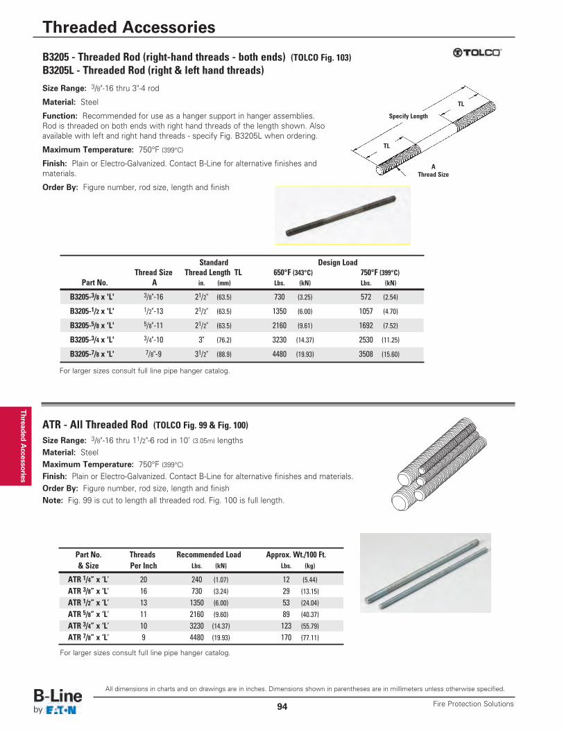
Threaded Accessories
B3205 - Threaded Rod (right-hand threads - both ends) (TOLCO Fig. 103)B3205L - Threaded Rod (right & left hand threads)
ATR - All Threaded Rod (TOLCO Fig. 99 & Fig. 100)
Size Range: 3/8"-16 thru 3"-4 rod
Material: Steel
Function: Recommended for use as a hanger support in hanger assemblies.Rod is threaded on both ends with right hand threads of the length shown. Alsoavailable with left and right hand threads - specify Fig. B3205L when ordering.
Maximum Temperature: 750°F (399°C)
Finish: Plain or Electro-Galvanized. Contact B-Line for alternative finishes andmaterials.
Order By: Figure number, rod size, length and finish
Size Range: 3/8"-16 thru 11/2"-6 rod in 10’ (3.05m) lengthsMaterial: SteelMaximum Temperature: 750°F (399°C)Finish: Plain or Electro-Galvanized. Contact B-Line for alternative finishes and materials.Order By: Figure number, rod size, length and finishNote: Fig. 99 is cut to length all threaded rod. Fig. 100 is full length.
AThread Size
TL
TL
Specify Length
Standard Design LoadThread Size Thread Length TL 650°F (343°C) 750°F (399°C)
Part No. A in. (mm) Lbs. (kN) Lbs. (kN)
B3205-3/8 x 'L' 3/8"-16 21/2" (63.5) 730 (3.25) 572 (2.54)
B3205-1/2 x 'L' 1/2"-13 21/2" (63.5) 1350 (6.00) 1057 (4.70)
B3205-5/8 x 'L' 5/8"-11 21/2" (63.5) 2160 (9.61) 1692 (7.52)
B3205-3/4 x 'L' 3/4"-10 3" (76.2) 3230 (14.37) 2530 (11.25)
B3205-7/8 x 'L' 7/8"-9 31/2" (88.9) 4480 (19.93) 3508 (15.60)
Part No. Threads Recommended Load Approx. Wt./100 Ft.& Size Per Inch Lbs. (kN) Lbs. (kg)
ATR 1/4” x ‘L’ 20 240 (1.07) 12 (5.44)
ATR 3/8” x ‘L’ 16 730 (3.24) 29 (13.15)
ATR 1/2” x ‘L’ 13 1350 (6.00) 53 (24.04)
ATR 5/8” x ‘L’ 11 2160 (9.60) 89 (40.37)
ATR 3/4” x ‘L’ 10 3230 (14.37) 123 (55.79)
ATR 7/8” x ‘L’ 9 4480 (19.93) 170 (77.11)
For larger sizes consult full line pipe hanger catalog.
For larger sizes consult full line pipe hanger catalog.
All dimensions in charts and on drawings are in inches. Dimensions shown in parentheses are in millimeters unless otherwise specified.
Threaded Accessories
Fire Protection Solutions94
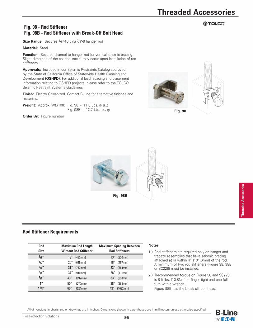
Thread
ed Accesso
ries
Fig. 98 - Rod StiffenerFig. 98B - Rod Stiffener with Break-Off Bolt Head
Size Range: Secures 3/8"-16 thru 7/8"-9 hanger rod
Material: Steel
Function: Secures channel to hanger rod for vertical seismic bracing.Slight distortion of the channel (strut) may occur upon installation of rodstiffeners.
Approvals: Included in our Seismic Restraints Catalog approvedby the State of California Office of Statewide Health Planning andDevelopment (OSHPD). For additional load, spacing and placementinformation relating to OSHPD projects, please refer to the TOLCOSeismic Restraint Systems Guidelines
Finish: Electro Galvanized. Contact B-Line for alternative finishes andmaterials.
Weight: Approx. Wt./100: Fig. 98 - 11.8 Lbs. (5.3kg)Fig. 98B - 12.7 Lbs. (5.7kg)
Order By: Figure number
Fig. 98B
Fig. 98
Notes:
1.) Rod stiffeners are required only on hanger andtrapeze assemblies that have seismic bracingattached at or within 4” (101.6mm) of the rod.A minimum of two rod stiffeners (Figure 98, 98B,or SC228) must be installed.
2.) Recommended torque on Figure 98 and SC228 is 8 ft-lbs. (10.8Nm) or finger tight and one full turn with a wrench.Figure 98B has the break off bolt head.
Rod Stiffener Requirements
Rod Maximum Rod Length Maximum Spacing BetweenSize Without Rod Stiffener Rod Stiffeners3/8” 19” (482mm) 13” (330mm)1/2” 25” (635mm) 18” (457mm)5/8” 31” (787mm) 23” (584mm)3/4” 37” (940mm) 28” (711mm)7/8” 43” (1092mm) 33” (838mm)
1” 50” (1270mm) 38” (965mm)11/4” 60” (1524mm) 43” (1092mm)
All dimensions in charts and on drawings are in inches. Dimensions shown in parentheses are in millimeters unless otherwise specified.
Threaded Accessories
95Fire Protection Solutions
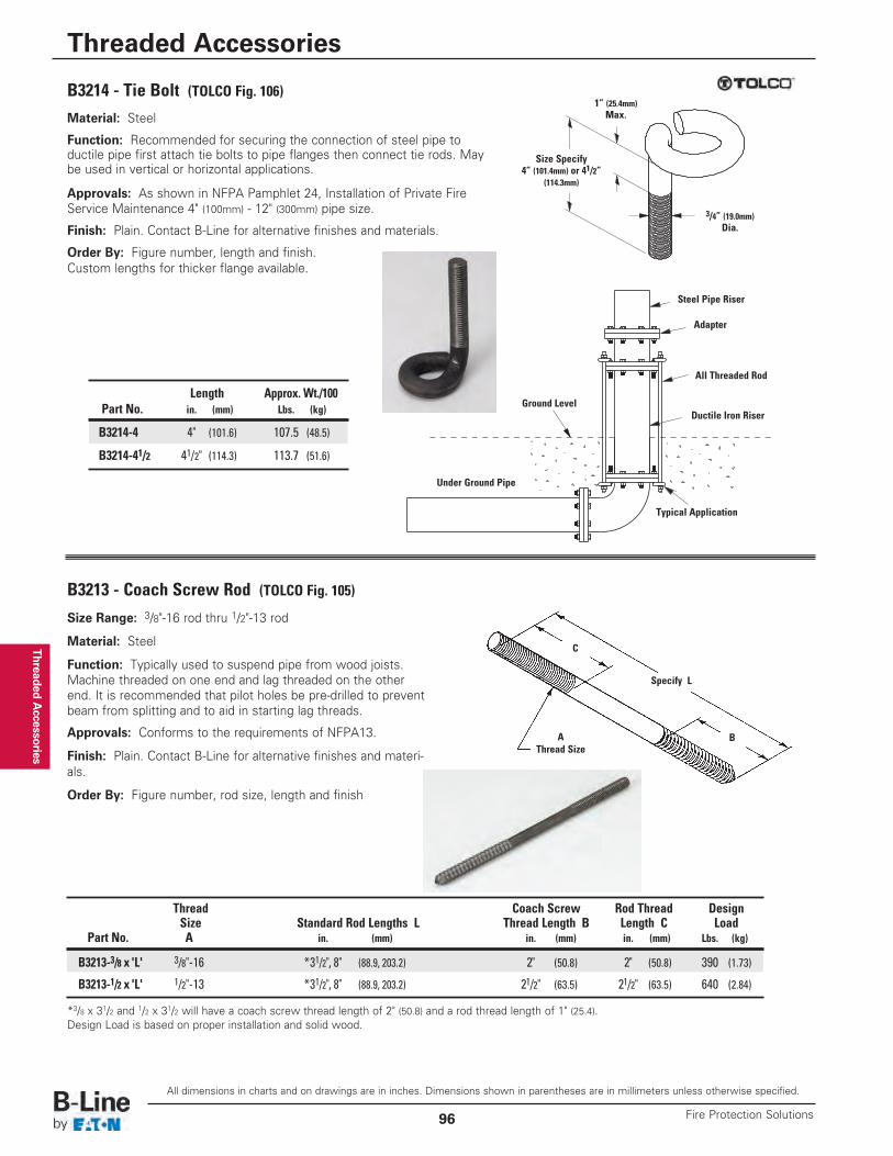
Threaded Accessories
B3214 - Tie Bolt (TOLCO Fig. 106)Material: Steel
Function: Recommended for securing the connection of steel pipe to ductile pipe first attach tie bolts to pipe flanges then connect tie rods. Maybe used in vertical or horizontal applications.
Approvals: As shown in NFPA Pamphlet 24, Installation of Private FireService Maintenance 4" (100mm) - 12" (300mm) pipe size.
Finish: Plain. Contact B-Line for alternative finishes and materials.
Order By: Figure number, length and finish.Custom lengths for thicker flange available.
Size Range: 3/8"-16 rod thru 1/2"-13 rod
Material: Steel
Function: Typically used to suspend pipe from wood joists.Machine threaded on one end and lag threaded on the otherend. It is recommended that pilot holes be pre-drilled to preventbeam from splitting and to aid in starting lag threads.
Approvals: Conforms to the requirements of NFPA13.
Finish: Plain. Contact B-Line for alternative finishes and materi-als.
Order By: Figure number, rod size, length and finish
B3213 - Coach Screw Rod (TOLCO Fig. 105)
*3/8 x 31/2 and 1/2 x 31/2 will have a coach screw thread length of 2" (50.8) and a rod thread length of 1" (25.4).Design Load is based on proper installation and solid wood.
AThread Size
B
C
Specify L
Size Specify4” (101.4mm) or 41/2”
(114.3mm)
Steel Pipe Riser
Adapter
Ground Level
All Threaded Rod
Ductile Iron Riser
Typical Application
Under Ground Pipe
1” (25.4mm)Max.
3/4” (19.0mm)Dia.
Thread Coach Screw Rod Thread DesignSize Standard Rod Lengths L Thread Length B Length C Load
Part No. A in. (mm) in. (mm) in. (mm) Lbs. (kg)
B3213-3/8 x 'L' 3/8"-16 *31/2", 8" (88.9, 203.2) 2" (50.8) 2" (50.8) 390 (1.73)
B3213-1/2 x 'L' 1/2"-13 *31/2", 8" (88.9, 203.2) 21/2" (63.5) 21/2" (63.5) 640 (2.84)
Length Approx. Wt./100Part No. in. (mm) Lbs. (kg)
B3214-4 4" (101.6) 107.5 (48.5)
B3214-41/2 41/2" (114.3) 113.7 (51.6)
All dimensions in charts and on drawings are in inches. Dimensions shown in parentheses are in millimeters unless otherwise specified.
Threaded Accessories
Fire Protection Solutions96
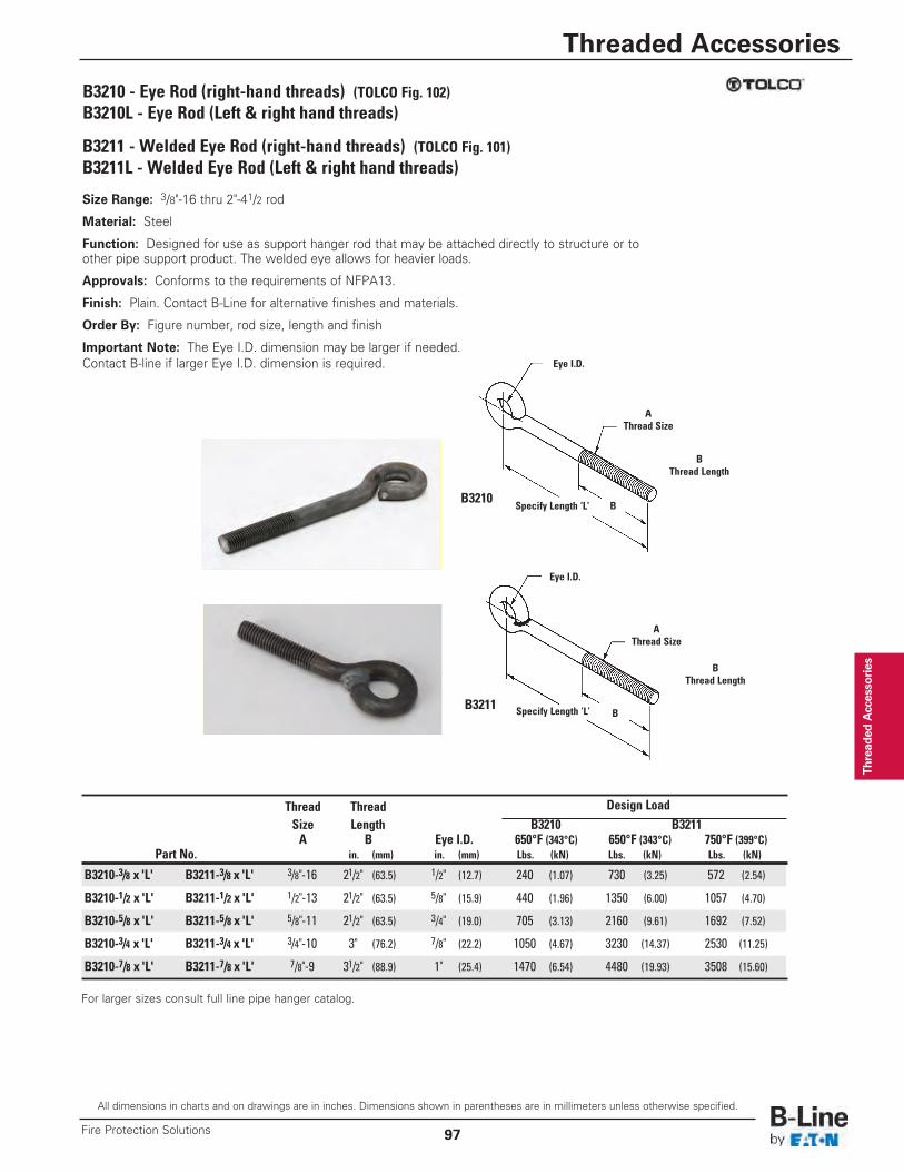
Thread
ed Accesso
ries
B3210 - Eye Rod (right-hand threads) (TOLCO Fig. 102)B3210L - Eye Rod (Left & right hand threads)
B3211 - Welded Eye Rod (right-hand threads) (TOLCO Fig. 101)B3211L - Welded Eye Rod (Left & right hand threads)
Size Range: 3/8"-16 thru 2"-41/2 rod
Material: Steel
Function: Designed for use as support hanger rod that may be attached directly to structure or toother pipe support product. The welded eye allows for heavier loads.
Approvals: Conforms to the requirements of NFPA13.
Finish: Plain. Contact B-Line for alternative finishes and materials.
Order By: Figure number, rod size, length and finish
Important Note: The Eye I.D. dimension may be larger if needed.Contact B-line if larger Eye I.D. dimension is required.
AThread Size
BThread Length
BThread Length
AThread Size
Specify Length ‘L’
Specify Length ‘L’
Eye I.D.
Eye I.D.
B
B
Thread Thread Design LoadSize Length B3210 B3211A B Eye I.D. 650°F (343°C) 650°F (343°C) 750°F (399°C)
Part No. in. (mm) in. (mm) Lbs. (kN) Lbs. (kN) Lbs. (kN)
B3210-3/8 x 'L' B3211-3/8 x 'L' 3/8"-16 21/2" (63.5) 1/2" (12.7) 240 (1.07) 730 (3.25) 572 (2.54)
B3210-1/2 x 'L' B3211-1/2 x 'L' 1/2"-13 21/2" (63.5) 5/8" (15.9) 440 (1.96) 1350 (6.00) 1057 (4.70)
B3210-5/8 x 'L' B3211-5/8 x 'L' 5/8"-11 21/2" (63.5) 3/4" (19.0) 705 (3.13) 2160 (9.61) 1692 (7.52)
B3210-3/4 x 'L' B3211-3/4 x 'L' 3/4"-10 3" (76.2) 7/8" (22.2) 1050 (4.67) 3230 (14.37) 2530 (11.25)
B3210-7/8 x 'L' B3211-7/8 x 'L' 7/8"-9 31/2" (88.9) 1" (25.4) 1470 (6.54) 4480 (19.93) 3508 (15.60)
B3210
B3211
For larger sizes consult full line pipe hanger catalog.
All dimensions in charts and on drawings are in inches. Dimensions shown in parentheses are in millimeters unless otherwise specified.
Threaded Accessories
97Fire Protection Solutions
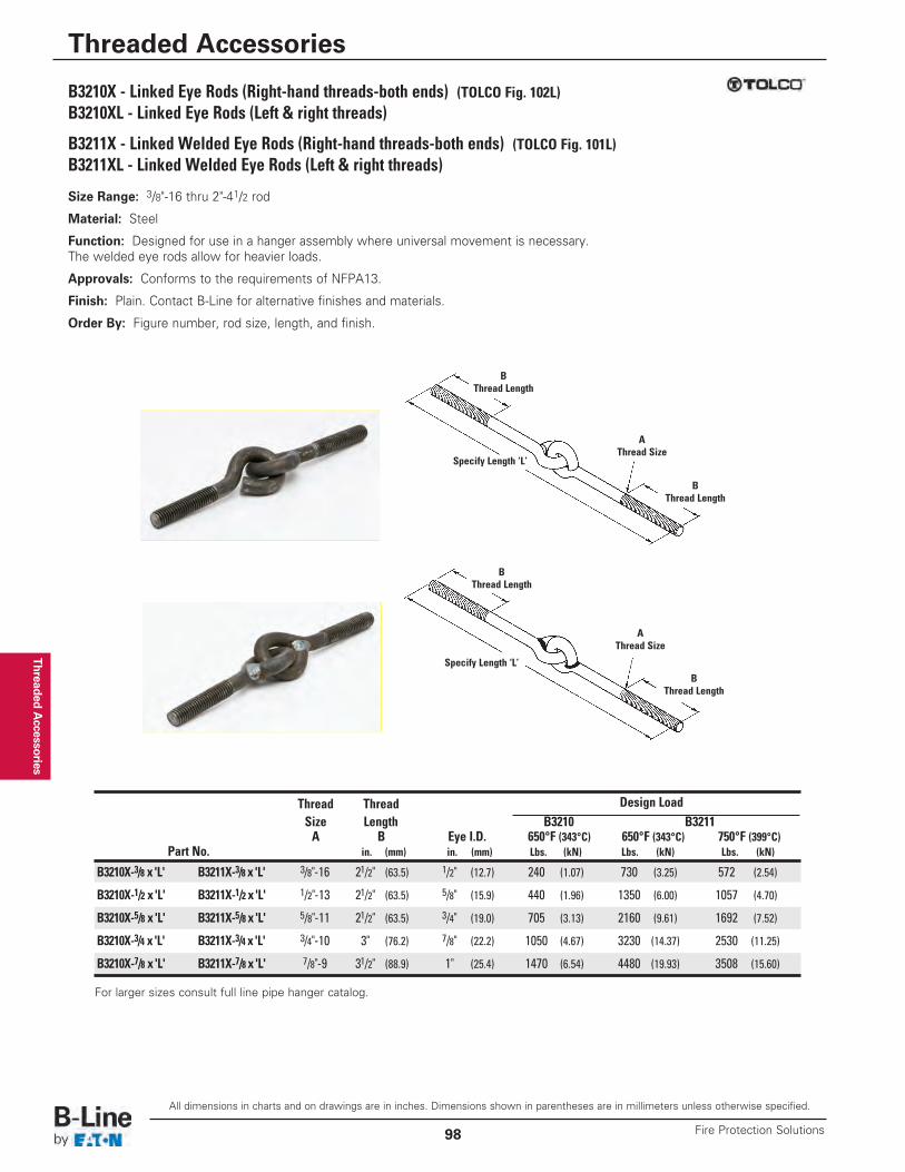
Threaded Accessories
B3210X - Linked Eye Rods (Right-hand threads-both ends) (TOLCO Fig. 102L)B3210XL - Linked Eye Rods (Left & right threads)
B3211X - Linked Welded Eye Rods (Right-hand threads-both ends) (TOLCO Fig. 101L)B3211XL - Linked Welded Eye Rods (Left & right threads)
Size Range: 3/8"-16 thru 2"-41/2 rod
Material: Steel
Function: Designed for use in a hanger assembly where universal movement is necessary.The welded eye rods allow for heavier loads.
Approvals: Conforms to the requirements of NFPA13.
Finish: Plain. Contact B-Line for alternative finishes and materials.
Order By: Figure number, rod size, length, and finish.
AThread Size
BThread Length
BThread Length
Specify Length ‘L’
AThread Size
BThread Length
BThread Length
Specify Length ‘L’
Thread Thread Design LoadSize Length B3210 B3211A B Eye I.D. 650°F (343°C) 650°F (343°C) 750°F (399°C)
Part No. in. (mm) in. (mm) Lbs. (kN) Lbs. (kN) Lbs. (kN)
B3210X-3/8 x 'L' B3211X-3/8 x 'L' 3/8"-16 21/2" (63.5) 1/2" (12.7) 240 (1.07) 730 (3.25) 572 (2.54)
B3210X-1/2 x 'L' B3211X-1/2 x 'L' 1/2"-13 21/2" (63.5) 5/8" (15.9) 440 (1.96) 1350 (6.00) 1057 (4.70)
B3210X-5/8 x 'L' B3211X-5/8 x 'L' 5/8"-11 21/2" (63.5) 3/4" (19.0) 705 (3.13) 2160 (9.61) 1692 (7.52)
B3210X-3/4 x 'L' B3211X-3/4 x 'L' 3/4"-10 3" (76.2) 7/8" (22.2) 1050 (4.67) 3230 (14.37) 2530 (11.25)
B3210X-7/8 x 'L' B3211X-7/8 x 'L' 7/8"-9 31/2" (88.9) 1" (25.4) 1470 (6.54) 4480 (19.93) 3508 (15.60)
For larger sizes consult full line pipe hanger catalog.
All dimensions in charts and on drawings are in inches. Dimensions shown in parentheses are in millimeters unless otherwise specified.
Threaded Accessories
Fire Protection Solutions98
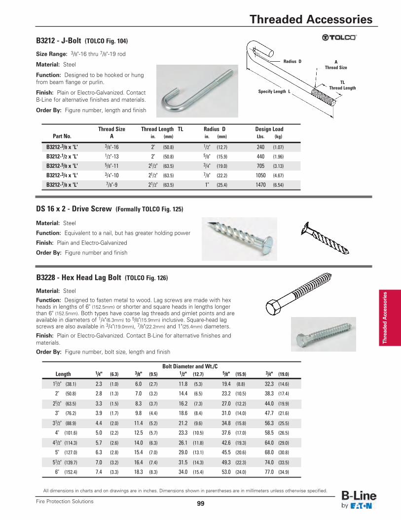
Thread
ed Accesso
ries
Size Range: 3/8"-16 thru 7/8"-19 rod
Material: Steel
Function: Designed to be hooked or hungfrom beam flange or purlin.
Finish: Plain or Electro-Galvanized. ContactB-Line for alternative finishes and materials.
Order By: Figure number, length and finish
B3212 - J-Bolt (TOLCO Fig. 104)
AThread Size
TLThread Length
Radius D
Specify Length L
Thread Size Thread Length TL Radius D Design LoadPart No. A in. (mm) in. (mm) Lbs. (kg)
B3212-3/8 x 'L' 3/8"-16 2" (50.8) 1/2" (12.7) 240 (1.07)
B3212-1/2 x 'L' 1/2"-13 2" (50.8) 5/8" (15.9) 440 (1.96)
B3212-5/8 x 'L' 5/8"-11 21/2" (63.5) 3/4" (19.0) 705 (3.13)
B3212-3/4 x 'L' 3/4"-10 21/2" (63.5) 7/8" (22.2) 1050 (4.67)
B3212-7/8 x 'L' 7/8"-9 21/2" (63.5) 1" (25.4) 1470 (6.54)
DS 16 x 2 - Drive Screw (Formally TOLCO Fig. 125)
Material: Steel
Function: Equivalent to a nail, but has greater holding power
Finish: Plain and Electro-Galvanized
Order By: Figure number and finish
B3228 - Hex Head Lag Bolt (TOLCO Fig. 126)
Material: Steel
Function: Designed to fasten metal to wood. Lag screws are made with hexheads in lengths of 6" (152.5mm) or shorter and square heads in lengths longerthan 6" (152.5mm). Both types have coarse lag threads and gimlet points and areavailable in diameters of 1/4"(6.3mm) to 5/8"(15.9mm) inclusive. Square-head lagscrews are also available in 3/4"(19.0mm), 7/8"(22.2mm) and 1"(25.4mm) diameters.
Finish: Plain or Electro-Galvanized. Contact B-Line for alternative finishes andmaterials.
Order By: Figure number, bolt size, length and finish
Bolt Diameter and Wt./CLength 1/4" (6.3) 3/8" (9.5) 1/2" (12.7) 5/8" (15.9) 3/4" (19.0)
11/2" (38.1) 2.3 (1.0) 6.0 (2.7) 11.8 (5.3) 19.4 (8.8) 32.3 (14.6)
2" (50.8) 2.8 (1.3) 7.0 (3.2) 14.4 (6.5) 23.2 (10.5) 38.3 (17.4)
21/2" (63.5) 3.3 (1.5) 8.3 (3.7) 16.2 (7.3) 27.0 (12.2) 44.0 (19.9)
3" (76.2) 3.9 (1.7) 9.8 (4.4) 18.6 (8.4) 31.0 (14.0) 47.7 (21.6)
31/2" (88.9) 4.4 (2.0) 11.4 (5.2) 21.2 (9.6) 34.8 (15.8) 56.3 (25.5)
4" (101.6) 5.0 (2.2) 12.5 (5.7) 23.3 (10.5) 37.6 (17.0) 58.5 (26.5)
41/2" (114.3) 5.7 (2.6) 14.0 (6.3) 26.1 (11.8) 42.6 (19.3) 64.0 (29.0)
5" (127.0) 6.3 (2.8) 15.4 (7.0) 29.0 (13.1) 45.5 (20.6) 68.0 (30.8)
51/2" (139.7) 7.0 (3.2) 16.4 (7.4) 31.5 (14.3) 49.3 (22.3) 74.0 (33.5)
6" (152.4) 7.4 (3.3) 18.3 (8.3) 34.0 (15.4) 53.0 (24.0) 77.0 (34.9)
All dimensions in charts and on drawings are in inches. Dimensions shown in parentheses are in millimeters unless otherwise specified.
Threaded Accessories
99Fire Protection Solutions
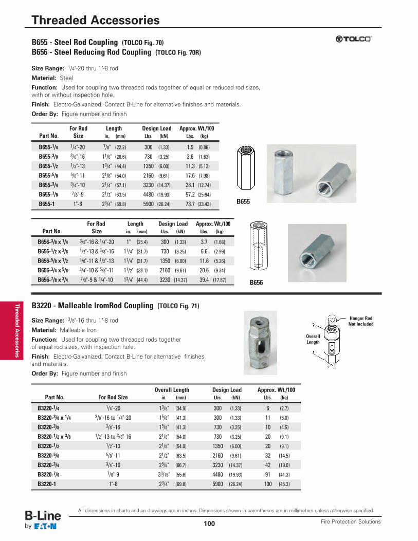
Threaded Accessories
Size Range: 1/4"-20 thru 1"-8 rod
Material: Steel
Function: Used for coupling two threaded rods together of equal or reduced rod sizes,with or without inspection hole.
Finish: Electro-Galvanized. Contact B-Line for alternative finishes and materials.
Order By: Figure number and finish
B655
B656
For Rod Length Design Load Approx. Wt./100Part No. Size in. (mm) Lbs. (kN) Lbs. (kg)
B656-3/8 x 1/4 3/8"-16 & 1/4"-20 1" (25.4) 300 (1.33) 3.7 (1.68)
B656-1/2 x 3/8 1/2"-13 & 3/8"-16 11/4" (31.7) 730 (3.25) 6.6 (2.99)
B656-5/8 x 1/2 5/8"-11 & 1/2"-13 11/4" (31.7) 1350 (6.00) 11.6 (5.26)
B656-3/4 x 5/8 3/4"-10 & 5/8"-11 11/2" (38.1) 2160 (9.61) 20.6 (9.34)
B656-7/8 x 3/4 7/8"-9 & 3/4"-10 13/4" (44.4) 3230 (14.37) 39.4 (17.87)
B655 - Steel Rod Coupling (TOLCO Fig. 70)B656 - Steel Reducing Rod Coupling (TOLCO Fig. 70R)
For Rod Length Design Load Approx. Wt./100Part No. Size in. (mm) Lbs. (kN) Lbs. (kg)
B655-1/4 1/4"-20 7/8" (22.2) 300 (1.33) 1.9 (0.86)
B655-3/8 3/8"-16 11/8" (28.6) 730 (3.25) 3.6 (1.63)
B655-1/2 1/2"-13 13/4" (44.4) 1350 (6.00) 11.3 (5.12)
B655-5/8 5/8"-11 21/8" (54.0) 2160 (9.61) 17.6 (7.98)
B655-3/4 3/4"-10 21/4" (57.1) 3230 (14.37) 28.1 (12.74)
B655-7/8 7/8"-9 21/2" (63.5) 4480 (19.93) 57.2 (25.94)
B655-1 1"-8 23/4" (69.8) 5900 (26.24) 73.7 (33.43)
B3220 - Malleable IromRod Coupling (TOLCO Fig. 71)
Size Range: 3/8"-16 thru 1"-8 rod
Material: Malleable Iron
Function: Used for coupling two threaded rods togetherof equal rod sizes, with inspection hole.
Finish: Electro-Galvanized. Contact B-Line for alternative finishesand materials.
Order By: Figure number and finish
Hanger RodNot Included
OverallLength
Overall Length Design Load Approx. Wt./100Part No. For Rod Size in. (mm) Lbs. (kN) Lbs. (kg)
B3220-1/4 1/4"-20 13/8" (34.9) 300 (1.33) 6 (2.7)
B3220-3/8 x 1/4 3/8"-16 to 1/4"-20 15/8" (41.3) 300 (1.33) 11 (5.0)
B3220-3/8 3/8"-16 15/8" (41.3) 730 (3.25) 10 (4.5)
B3220-1/2 x 3/8 1/2"-13 to 3/8"-16 21/8" (54.0) 730 (3.25) 20 (9.1)
B3220-1/2 1/2"-13 21/8" (54.0) 1350 (6.00) 20 (9.1)
B3220-5/8 5/8"-11 21/2" (63.5) 2160 (9.61) 32 (14.5)
B3220-3/4 3/4"-10 25/8" (66.7) 3230 (14.37) 42 (19.0)
B3220-7/8 7/8"-9 33/16" (55.6) 4480 (19.93) 91 (41.3)
B3220-1 1"-8 23/4" (69.8) 5900 (26.24) 100 (45.3)
All dimensions in charts and on drawings are in inches. Dimensions shown in parentheses are in millimeters unless otherwise specified.
Threaded Accessories
Fire Protection Solutions100
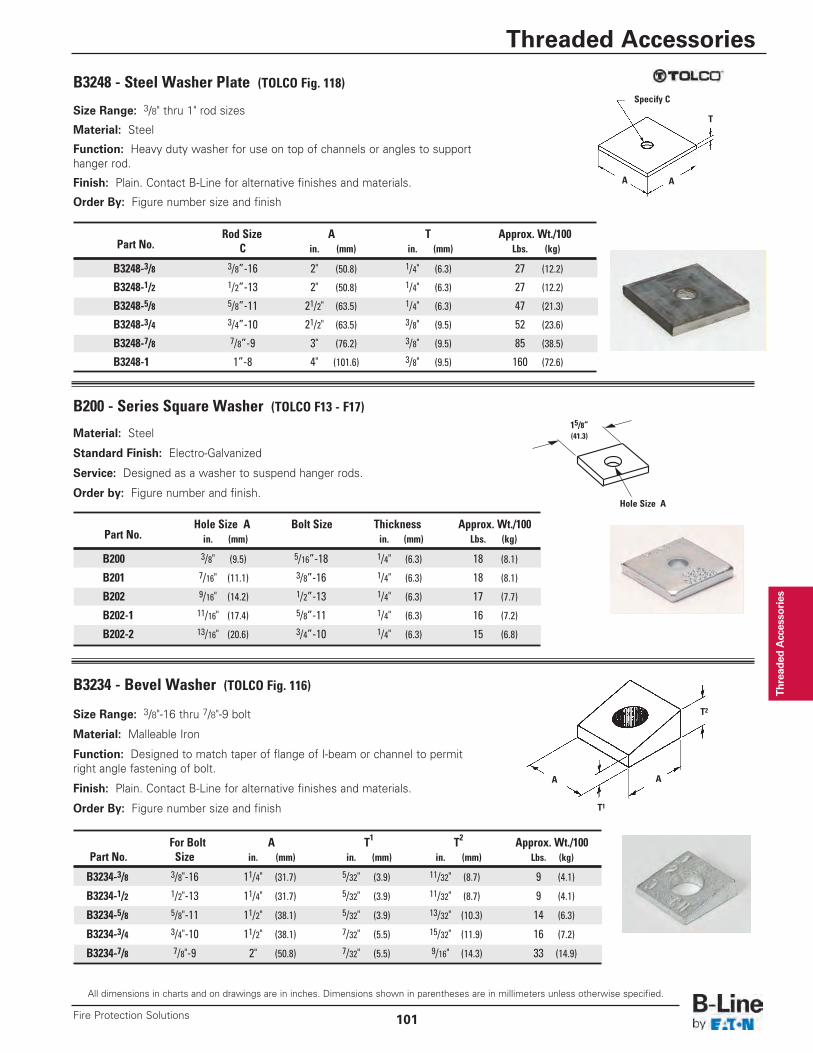
Thread
ed Accesso
ries
Size Range: 3/8" thru 1" rod sizes
Material: Steel
Function: Heavy duty washer for use on top of channels or angles to supporthanger rod.
Finish: Plain. Contact B-Line for alternative finishes and materials.
Order By: Figure number size and finish
B3248 - Steel Washer Plate (TOLCO Fig. 118)Specify C
T
AA
Rod Size A T Approx. Wt./100Part No. C in. (mm) in. (mm) Lbs. (kg)
B3248-3/8 3/8”-16 2" (50.8) 1/4" (6.3) 27 (12.2)
B3248-1/2 1/2”-13 2" (50.8) 1/4" (6.3) 27 (12.2)
B3248-5/8 5/8”-11 21/2" (63.5) 1/4" (6.3) 47 (21.3)
B3248-3/4 3/4”-10 21/2" (63.5) 3/8" (9.5) 52 (23.6)
B3248-7/8 7/8”-9 3" (76.2) 3/8" (9.5) 85 (38.5)
B3248-1 1”-8 4" (101.6) 3/8" (9.5) 160 (72.6)
Size Range: 3/8"-16 thru 7/8"-9 bolt
Material: Malleable Iron
Function: Designed to match taper of flange of I-beam or channel to permitright angle fastening of bolt.
Finish: Plain. Contact B-Line for alternative finishes and materials.
Order By: Figure number size and finish
B3234 - Bevel Washer (TOLCO Fig. 116)
T1
T2
AA
For Bolt A T1 T2 Approx. Wt./100Part No. Size in. (mm) in. (mm) in. (mm) Lbs. (kg)
B3234-3/8 3/8"-16 11/4" (31.7) 5/32" (3.9) 11/32" (8.7) 9 (4.1)
B3234-1/2 1/2"-13 11/4" (31.7) 5/32" (3.9) 11/32" (8.7) 9 (4.1)
B3234-5/8 5/8"-11 11/2" (38.1) 5/32" (3.9) 13/32" (10.3) 14 (6.3)
B3234-3/4 3/4"-10 11/2" (38.1) 7/32" (5.5) 15/32" (11.9) 16 (7.2)
B3234-7/8 7/8"-9 2" (50.8) 7/32" (5.5) 9/16" (14.3) 33 (14.9)
Material: Steel
Standard Finish: Electro-Galvanized
Service: Designed as a washer to suspend hanger rods.
Order by: Figure number and finish.
B200 - Series Square Washer (TOLCO F13 - F17)
Hole Size A Bolt Size Thickness Approx. Wt./100Part No. in. (mm) in. (mm) Lbs. (kg)
B200 3/8" (9.5) 5/16”-18 1/4" (6.3) 18 (8.1)
B201 7/16" (11.1) 3/8”-16 1/4" (6.3) 18 (8.1)
B202 9/16" (14.2) 1/2”-13 1/4" (6.3) 17 (7.7)
B202-1 11/16" (17.4) 5/8”-11 1/4" (6.3) 16 (7.2)
B202-2 13/16" (20.6) 3/4”-10 1/4" (6.3) 15 (6.8)
15/8”(41.3)
Hole Size A
All dimensions in charts and on drawings are in inches. Dimensions shown in parentheses are in millimeters unless otherwise specified.
Threaded Accessories
101Fire Protection Solutions
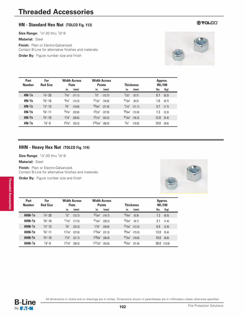
Threaded Accessories
Size Range: 1/4"-20 thru 7/8"-9
Material: Steel
Finish: Plain or Electro-Galvanized.Contact B-Line for alternative finishes and materials.
Order By: Figure number size and finish
HN - Standard Hex Nut (TOLCO Fig. 113)
Part For Width Across Width Across Approx.Number Rod Size Flats Points Thickness Wt./100
in. (mm) in. (mm) in. (mm) lbs. (kg)
HN-1/4 1⁄4"-20 7⁄16" (11.1) 1⁄2" (12.7) 7/32" (5.7) 0.7 (0.3)
HN-3/8 3⁄8"-16 9⁄16" (14.3) 21/32" (16.6) 21/64" (8.3) 1.6 (0.7)
HN-1/2 1⁄2"-13 3⁄4" (19.0) 55/64" (21.8) 7/16" (11.1) 3.7 (1.7)
HN-5/8 5⁄8"-11 15⁄16" (23.8) 13/32" (27.8) 35/64" (13.9) 7.3 (3.3)
HN-3/4 3⁄4"-10 11⁄8" (28.6) 15/16" (33.3) 41/64" (16.3) 12.0 (5.4)
HN-7/8 7⁄8"-9 15⁄16" (33.3) 133/64" (38.5) 3/4" (19.0) 19.0 (8.6)
Size Range: 1/4"-20 thru 7/8"-9
Material: Steel
Finish: Plain or Electro-Galvanized.Contact B-Line for alternative finishes and materials.
Order By: Figure number size and finish
HHN - Heavy Hex Nut (TOLCO Fig. 114)
Part For Width Across Width Across Approx.Number Rod Size Flats Points Thickness Wt./100
in. (mm) in. (mm) in. (mm) lbs. (kg)
HHN-1/4 1⁄4"-20 1⁄2" (12.7) 37/64" (14.7) 15/64" (5.9) 1.2 (0.5)
HHN-3/8 3⁄8"-16 11⁄16" (17.5) 51/64" (20.2) 23/64" (9.1) 3.1 (1.4)
HHN-1/2 1⁄2"-13 7⁄8" (22.2) 11⁄8" (28.6) 31/64" (12.3) 6.5 (2.9)
HHN-5/8 5⁄8"-11 11⁄16" (27.0) 115⁄64" (31.3) 39/64" (15.5) 12.0 (5.4)
HHN-3/4 3⁄4"-10 11⁄4" (31.7) 129⁄64" (36.9) 47/64" (18.6) 19.0 (8.6)
HHN-7/8 7⁄8"-9 17⁄16" (36.5) 121⁄32" (42.6) 55/64" (21.8) 30.0 (13.6)
All dimensions in charts and on drawings are in inches. Dimensions shown in parentheses are in millimeters unless otherwise specified.
Threaded Accessories
Fire Protection Solutions102
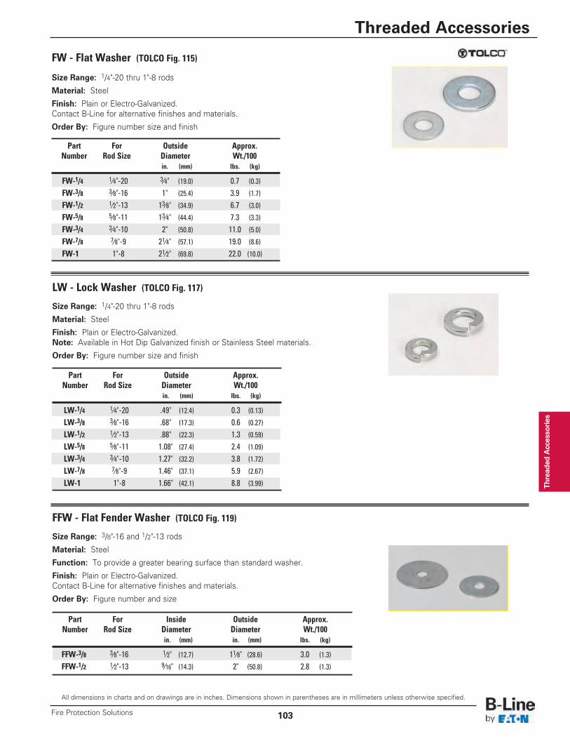
Thread
ed Accesso
ries
Size Range: 1/4"-20 thru 1"-8 rods
Material: Steel
Finish: Plain or Electro-Galvanized.Contact B-Line for alternative finishes and materials.
Order By: Figure number size and finish
FW - Flat Washer (TOLCO Fig. 115)
Part For Outside Approx.Number Rod Size Diameter Wt./100
in. (mm) lbs. (kg)
FW-1/4 1⁄4"-20 3⁄4" (19.0) 0.7 (0.3)
FW-3/8 3⁄8"-16 1" (25.4) 3.9 (1.7)
FW-1/2 1⁄2"-13 13⁄8" (34.9) 6.7 (3.0)
FW-5/8 5⁄8"-11 13⁄4" (44.4) 7.3 (3.3)
FW-3/4 3⁄4"-10 2" (50.8) 11.0 (5.0)
FW-7/8 7⁄8"-9 21⁄4" (57.1) 19.0 (8.6)
FW-1 1"-8 21⁄2" (69.8) 22.0 (10.0)
Part For Outside Approx.Number Rod Size Diameter Wt./100
in. (mm) lbs. (kg)
LW-1/4 1⁄4"-20 .49" (12.4) 0.3 (0.13)
LW-3/8 3⁄8"-16 .68" (17.3) 0.6 (0.27)
LW-1/2 1⁄2"-13 .88" (22.3) 1.3 (0.59)
LW-5/8 5⁄8"-11 1.08" (27.4) 2.4 (1.09)
LW-3/4 3⁄4"-10 1.27" (32.2) 3.8 (1.72)
LW-7/8 7⁄8"-9 1.46" (37.1) 5.9 (2.67)
LW-1 1"-8 1.66" (42.1) 8.8 (3.99)
Size Range: 1/4"-20 thru 1"-8 rods
Material: Steel
Finish: Plain or Electro-Galvanized.Note: Available in Hot Dip Galvanized finish or Stainless Steel materials.
Order By: Figure number size and finish
LW - Lock Washer (TOLCO Fig. 117)
Size Range: 3/8"-16 and 1/2"-13 rods
Material: Steel
Function: To provide a greater bearing surface than standard washer.
Finish: Plain or Electro-Galvanized.Contact B-Line for alternative finishes and materials.
Order By: Figure number and size
FFW - Flat Fender Washer (TOLCO Fig. 119)
Part For Inside Outside Approx.Number Rod Size Diameter Diameter Wt./100
in. (mm) in. (mm) lbs. (kg)
FFW-3/8 3⁄8"-16 1⁄2" (12.7) 11⁄8" (28.6) 3.0 (1.3)
FFW-1/2 1⁄2"-13 9⁄16" (14.3) 2" (50.8) 2.8 (1.3)
All dimensions in charts and on drawings are in inches. Dimensions shown in parentheses are in millimeters unless otherwise specified.
Threaded Accessories
103Fire Protection Solutions
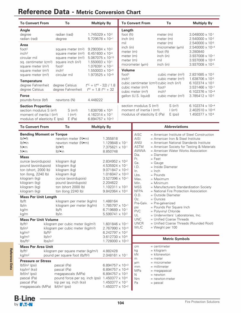
Reference D
ata
To Convert From To Multiply By
Angledegree radian (rad) 1.745329 x 10⁻²radian (rad) degree 5.729578 x 10+1
Areafoot2 square meter (m2) 9.290304 x 10⁻²inch2 square meter (m2) 6.451600 x 10⁻⁴circular mil square meter (m2) 5.067075 x 10⁻¹⁰sq. centimeter (cm2) square inch (in2) 1.550003 x 10⁻¹square meter (m2) foot2 1.076391 x 10+1square meter (m2) inch2 1.550003 x 10+3square meter (m2) circular mil 1.973525 x 10+9
Temperaturedegree Fahrenheit degree Celsius t°C = (t°F - 32) / 1.8degree Celsius degree Fahrenheit t°F = 1.8 t°C + 32
Forcepounds-force (lbf) newtons (N) 4.448222
Section Propertiessection modulus S (in3) S (m3) 1.638706 x 10⁻⁵moment of inertia I (in4) I (m4) 4.162314 x 10⁻⁷modulus of elasticity E (psi) E (Pa) 6.894757 x 10+3
To Convert From To Multiply By
Bending Moment or Torquelbf•ft newton meter (N•m) 1.355818lbf•in newton meter (N•m) 1.129848 x 10⁻¹N•m lbf•ft 7.375621 x 10⁻¹N•m lbf•in 8.850748
Massounce (avoirdupois) kilogram (kg) 2.834952 x 10⁻²pound (avoirdupois) kilogram (kg) 4.535924 x 10⁻¹ton (short, 2000 lb) kilogram (kg) 9.071847 x 10+2ton (long, 2240 lb) kilogram (kg) 1.016047 x 10+3kilogram (kg) ounce (avoirdupois) 3.527396 x 10+1kilogram (kg) pound (avoirdupois) 2.204622kilogram (kg) ton (short 2000 lb) 1.102311 x 10⁻³kilogram (kg) ton (long 2240 lb) 9.842064 x 10⁻⁴
Mass Per Unit Lengthlb/ft kilogram per meter (kg/m) 1.488164lb/in kilogram per meter (kg/m) 1.785797 x 10+1kg/m lb/ft 6.719689 x 10⁻¹kg/m lb/in 5.599741 x 10⁻²
Mass Per Unit Volumelb/ft3 kilogram per cubic meter (kg/m3) 1.601846 x 10+1lb/in3 kilogram per cubic meter (kg/m3) 2.767990 x 10+4kg/m3 lb/ft3 6.242797 x 10⁻²kg/m3 lb/in3 3.612730 x 10⁻⁵lbs/ft3 lbs/in3 1.728000 x 10+3
Mass Per Area Unitlb/ft2 kilogram per square meter (kg/m2) 4.882428kg/m2 pound per square foot (lb/ft2) 2.048161 x 10⁻¹
Pressure or Stresslbf/in2 (psi) pascal (Pa) 6.894757 x 10+3kip/in2 (ksi) pascal (Pa) 6.894757 x 10+6lbf/in2 (psi) megapascals (MPa) 6.894757 x 10⁻³pascal (Pa) pound force per sq. inch (psi) 1.450377 x 10⁻⁴pascal (Pa) kip per sq. inch (ksi) 1.450377 x 10⁻⁷megapascals (MPa) lbf/in2 (psi) 1.450377 x 10+2
To Convert From To Multiply By
Lengthfoot (ft) meter (m) 3.048000 x 10⁻¹inch (in) meter (m) 2.540000 x 10⁻²mil meter (m) 2.540000 x 10⁻⁵inch (in) micrometer (μm) 2.540000 x 10+4meter (m) foot (ft) 3.280840meter (m) inch (in) 3.937008 x 10+1meter (m) mil 3.937008 x 10+4micrometer (μm) inch (in) 3.937008 x 10⁻⁵
Volumefoot3 cubic meter (m3) 2.831685 x 10⁻²inch3 cubic meter (m3) 1.638706 x 10⁻⁵cubic centimeter (cm3) cubic inch (in3) 6.102374 x 10⁻²cubic meter (m3) foot3 3.531466 x 10+1cubic meter (m3) inch3 6.102376 x 10+4gallon (U.S. liquid) cubic meter (m3) 3.785412 x 10⁻³
section modulus S (m3) S (in3) 6.102374 x 10+4moment of inertia I (m4) I (in4) 2.402510 x 10+6modulus of elasticity E (Pa) E (psi) 1.450377 x 10⁻⁴
Abbreviations
AISC = American Institute of Steel ConstructionAISI = American Iron & Steel InstituteANSI = American National Standards InstituteASTM = American Society for Testing & MaterialsAWWA = American Water Works AssociationDia. = DiameterFt. = FeetGa. = GaugeI.D. = Inside DiameterIn. = InchLbs. = PoundsMax. = MaximumMin. = MinimumMSS = Manufacturers Standardization SocietyNFPA = National Fire Protection AssociationO.D. = Outside DiameterOz. = OuncesPre-Galv. = Pre-galvanizedpsi = Pounds Per Square InchPVC = Polyvinyl ChlorideUL = Underwriters' Laboratories, Inc.UNC = Unified Coarse ThreadsUNCR = Unified Coarse Threads (Rounded Root)Wt./C = Weight per 100
Metric Symbols
cm = centimeterkg = kilogramkN = kilonewtonm = meterμm = micrometermm = millimeterMPa = megapascalN = newtonNm = newton-meterPa = pascal
Reference Data - Metric Conversion Chart
Fire Protection Solutions104
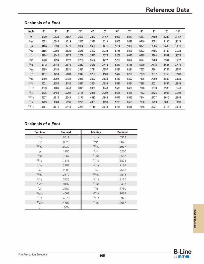
Reference Data
Inch 0" 1" 2" 3" 4" 5" 6" 7" 8" 9" 10" 11"
0 .0000 .0833 .1667 .2500 .3330 .4167 .5000 .5833 .6667 .7500 .8333 .91671/16 .0052 .0085 .1719 .2552 .3385 .4219 .5052 .5885 .6719 .7552 .8385 .92191/8 .0104 .0938 .1771 .2604 .3438 .4271 .5104 .5938 .6771 .7604 .8438 .92713/16 .0156 .0990 .1823 .2656 .3490 .4323 .5156 .5990 .6823 .7656 .8490 .93231/4 .0208 .1042 .1875 .2708 .3542 .4375 .5208 .6042 .6875 .7708 .8542 .93755/16 .0260 .1094 .1927 .2760 .3594 .4427 .5260 .6094 .6927 .7760 .8594 .94273/8 .0313 .1146 .1979 .2812 .3646 .4479 .5313 .6146 .6979 .7813 .8646 .94797/16 .0365 .1198 .2031 .2891 .3724 .4557 .5391 .6224 .7057 .7891 .8724 .95571/2 .0417 .1250 .2083 .2917 .3750 .4583 .5417 .6250 .7083 .7917 .8750 .95839/16 .0469 .1302 .2135 .2969 .3802 .4635 .5469 .6302 .7135 .7969 .8802 .96355/8 .0521 .1354 .2188 .3021 .3854 .4688 .5521 .6354 .7188 .8021 .8854 .968811/16 .0573 .1406 .2240 .3073 .3906 .4740 .5573 .6406 .7240 .8073 .8906 .97403/4 .0625 .1458 .2292 .3125 .3958 .4792 .5625 .6458 .7292 .8125 .8958 .979213/16 .0677 .1510 .2344 .3177 .4010 .4844 .5677 .6510 .7344 .8177 .9010 .98447/8 .0729 .1563 .2396 .3229 .4063 .4896 .5729 .6563 .7396 .8229 .9063 .989615/16 .0781 .1615 .2448 .3281 .4118 .4948 .5781 .6615 .7448 .8221 .9115 .9948
Decimals of a Foot
Decimals of a Foot
Fraction Decimal1/32 .03121/16 .06253/32 .09371/8 .12505/32 .15623/16 .18757/32 .21871/4 .25009/32 .28125/16 .312511/32 .34373/8 .375013/32 .40627/16 .437515/32 .46871/2 .500
Fraction Decimal17/32 .53129/16 .562519/32 .59375/8 .625021/32 .656211/16 .687523/32 .71873/4 .750025/32 .781213/16 .812527/32 .84377/8 .875029/32 .906215/16 .937531/32 .9687
Reference Data
105Fire Protection Solutions
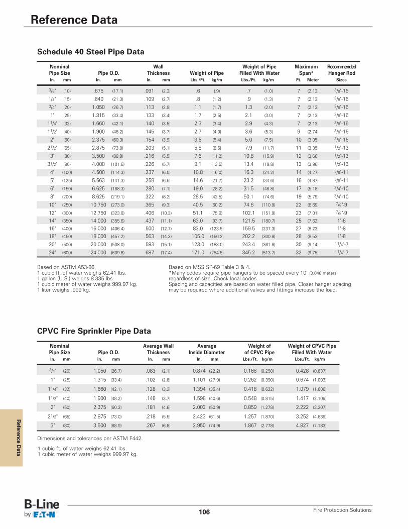
Reference D
ata
Schedule 40 Steel Pipe Data
Based on ASTM A53-86.1 cubic ft. of water weighs 62.41 lbs.1 gallon (U.S.) weighs 8.335 lbs.1 cubic meter of water weighs 999.97 kg.1 liter weighs .999 kg.
1 cubic ft. of water weighs 62.41 lbs.1 cubic meter of water weighs 999.97 kg.
Nominal Wall Weight of Pipe Maximum RecommendedPipe Size Pipe O.D. Thickness Weight of Pipe Filled With Water Span* Hanger RodIn. mm In. mm In. mm Lbs./Ft. kg/m Lbs./Ft. kg/m Ft. Meter Sizes
3/8" (10) .675 (17.1) .091 (2.3) .6 (.9) .7 (1.0) 7 (2.13) 3/8"-161/2" (15) .840 (21.3) .109 (2.7) .8 (1.2) .9 (1.3) 7 (2.13) 3/8"-163/4" (20) 1.050 (26.7) .113 (2.9) 1.1 (1.7) 1.3 (2.0) 7 (2.13) 3/8"-16
1" (25) 1.315 (33.4) .133 (3.4) 1.7 (2.5) 2.1 (3.0) 7 (2.13) 3/8"-16
11/4" (32) 1.660 (42.1) .140 (3.5) 2.3 (3.4) 2.9 (4.3) 7 (2.13) 3/8"-16
11/2" (40) 1.900 (48.2) .145 (3.7) 2.7 (4.0) 3.6 (5.3) 9 (2.74) 3/8"-16
2" (50) 2.375 (60.3) .154 (3.9) 3.6 (5.4) 5.0 (7.5) 10 (3.05) 3/8"-16
21/2" (65) 2.875 (73.0) .203 (5.1) 5.8 (8.6) 7.9 (11.7) 11 (3.35) 1/2"-13
3" (80) 3.500 (88.9) .216 (5.5) 7.6 (11.2) 10.8 (15.9) 12 (3.66) 1/2"-13
31/2" (90) 4.000 (101.6) .226 (5.7) 9.1 (13.5) 13.4 (19.8) 13 (3.96) 1/2"-13
4" (100) 4.500 (114.3) .237 (6.0) 10.8 (16.0) 16.3 (24.2) 14 (4.27) 5/8"-11
5" (125) 5.563 (141.3) .258 (6.5) 14.6 (21.7) 23.2 (34.6) 16 (4.87) 5/8"-11
6" (150) 6.625 (168.3) .280 (7.1) 19.0 (28.2) 31.5 (46.8) 17 (5.18) 3/4"-10
8" (200) 8.625 (219.1) .322 (8.2) 28.5 (42.5) 50.1 (74.6) 19 (5.79) 3/4"-10
10" (250) 10.750 (273.0) .365 (9.3) 40.5 (60.2) 74.6 (110.9) 22 (6.69) 7/8"-9
12" (300) 12.750 (323.8) .406 (10.3) 51.1 (75.9) 102.1 (151.9) 23 (7.01) 7/8"-914" (350) 14.000 (355.6) .437 (11.1) 63.0 (93.7) 121.5 (180.7) 25 (7.62) 1"-816" (400) 16.000 (406.4) .500 (12.7) 83.0 (123.5) 159.5 (237.3) 27 (8.23) 1"-818" (450) 18.000 (457.2) .563 (14.3) 105.0 (156.2) 202.2 (300.8) 28 (8.53) 1"-8
20" (500) 20.000 (508.0) .593 (15.1) 123.0 (183.0) 243.4 (361.8) 30 (9.14) 11/4"-7
24" (600) 24.000 (609.6) .687 (17.4) 171.0 (254.5) 345.2 (513.7) 32 (9.75) 11/4"-7
Based on MSS SP-69 Table 3 & 4.*Many codes require pipe hangers to be spaced every 10' (3.048 meters)regardless of size. Check local codes.Spacing and capacities are based on water filled pipe. Closer hanger spacingmay be required where additional valves and fittings increase the load.
CPVC Fire Sprinkler Pipe Data
Nominal Average Wall Average Weight of Weight of CPVC PipePipe Size Pipe O.D. Thickness Inside Diameter of CPVC Pipe Filled With WaterIn. mm In. mm In. mm In. mm Lbs./Ft. kg/m Lbs./Ft. kg/m
3/4" (20) 1.050 (26.7) .083 (2.1) 0.874 (22.2) 0.168 (0.250) 0.428 (0.637)
1" (25) 1.315 (33.4) .102 (2.6) 1.101 (27.9) 0.262 (0.390) 0.674 (1.003)
11/4" (32) 1.660 (42.1) .128 (3.2) 1.394 (35.4) 0.418 (0.622) 1.079 (1.606)
11/2" (40) 1.900 (48.2) .146 (3.7) 1.598 (40.6) 0.548 (0.815) 1.417 (2.109)
2" (50) 2.375 (60.3) .181 (4.6) 2.003 (50.9) 0.859 (1.278) 2.222 (3.307)
21/2" (65) 2.875 (73.0) .218 (5.5) 2.423 (61.5) 1.257 (1.870) 3.252 (4.839)
3" (80) 3.500 (88.9) .267 (6.8) 2.950 (74.9) 1.867 (2.778) 4.827 (7.183)
Dimensions and tolerances per ASTM F442.
Reference Data
Fire Protection Solutions106
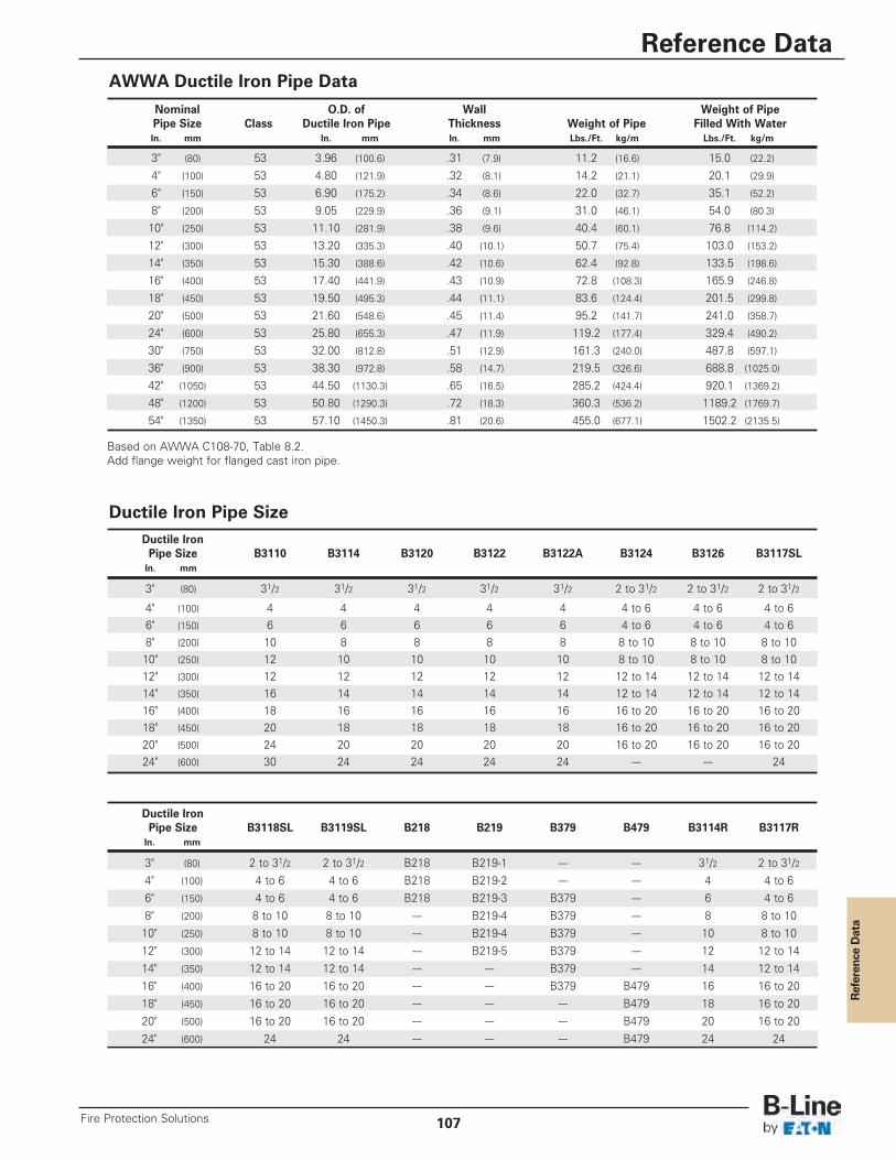
Reference Data
AWWA Ductile Iron Pipe Data
Based on AWWA C108-70, Table 8.2.Add flange weight for flanged cast iron pipe.
Nominal O.D. of Wall Weight of PipePipe Size Class Ductile Iron Pipe Thickness Weight of Pipe Filled With WaterIn. mm In. mm In. mm Lbs./Ft. kg/m Lbs./Ft. kg/m
3" (80) 53 3.96 (100.6) .31 (7.9) 11.2 (16.6) 15.0 (22.2)
4" (100) 53 4.80 (121.9) .32 (8.1) 14.2 (21.1) 20.1 (29.9)
6" (150) 53 6.90 (175.2) .34 (8.6) 22.0 (32.7) 35.1 (52.2)
8" (200) 53 9.05 (229.9) .36 (9.1) 31.0 (46.1) 54.0 (80.3)
10" (250) 53 11.10 (281.9) .38 (9.6) 40.4 (60.1) 76.8 (114.2)
12" (300) 53 13.20 (335.3) .40 (10.1) 50.7 (75.4) 103.0 (153.2)
14" (350) 53 15.30 (388.6) .42 (10.6) 62.4 (92.8) 133.5 (198.6)
16" (400) 53 17.40 (441.9) .43 (10.9) 72.8 (108.3) 165.9 (246.8)
18" (450) 53 19.50 (495.3) .44 (11.1) 83.6 (124.4) 201.5 (299.8)
20" (500) 53 21.60 (548.6) .45 (11.4) 95.2 (141.7) 241.0 (358.7)
24" (600) 53 25.80 (655.3) .47 (11.9) 119.2 (177.4) 329.4 (490.2)
30" (750) 53 32.00 (812.8) .51 (12.9) 161.3 (240.0) 487.8 (597.1)
36" (900) 53 38.30 (972.8) .58 (14.7) 219.5 (326.6) 688.8 (1025.0)
42" (1050) 53 44.50 (1130.3) .65 (16.5) 285.2 (424.4) 920.1 (1369.2)
48" (1200) 53 50.80 (1290.3) .72 (18.3) 360.3 (536.2) 1189.2 (1769.7)
54" (1350) 53 57.10 (1450.3) .81 (20.6) 455.0 (677.1) 1502.2 (2135.5)
Ductile Iron Pipe Size B3110 B3114 B3120 B3122 B3122A B3124 B3126 B3117SLIn. mm
3" (80) 31/2 31/2 31/2 31/2 31/2 2 to 31/2 2 to 31/2 2 to 31/2
4" (100) 4 4 4 4 4 4 to 6 4 to 6 4 to 66" (150) 6 6 6 6 6 4 to 6 4 to 6 4 to 68" (200) 10 8 8 8 8 8 to 10 8 to 10 8 to 1010" (250) 12 10 10 10 10 8 to 10 8 to 10 8 to 1012" (300) 12 12 12 12 12 12 to 14 12 to 14 12 to 1414" (350) 16 14 14 14 14 12 to 14 12 to 14 12 to 1416" (400) 18 16 16 16 16 16 to 20 16 to 20 16 to 2018" (450) 20 18 18 18 18 16 to 20 16 to 20 16 to 2020" (500) 24 20 20 20 20 16 to 20 16 to 20 16 to 2024" (600) 30 24 24 24 24 --- --- 24
Ductile Iron Pipe Size
Ductile Iron Pipe Size B3118SL B3119SL B218 B219 B379 B479 B3114R B3117RIn. mm
3" (80) 2 to 31/2 2 to 31/2 B218 B219-1 --- --- 31/2 2 to 31/24" (100) 4 to 6 4 to 6 B218 B219-2 --- --- 4 4 to 66" (150) 4 to 6 4 to 6 B218 B219-3 B379 --- 6 4 to 68" (200) 8 to 10 8 to 10 --- B219-4 B379 --- 8 8 to 1010" (250) 8 to 10 8 to 10 --- B219-4 B379 --- 10 8 to 1012" (300) 12 to 14 12 to 14 --- B219-5 B379 --- 12 12 to 1414" (350) 12 to 14 12 to 14 --- --- B379 --- 14 12 to 1416" (400) 16 to 20 16 to 20 --- --- B379 B479 16 16 to 2018" (450) 16 to 20 16 to 20 --- --- --- B479 18 16 to 2020" (500) 16 to 20 16 to 20 --- --- --- B479 20 16 to 2024" (600) 24 24 --- --- --- B479 24 24
Reference Data
107Fire Protection Solutions
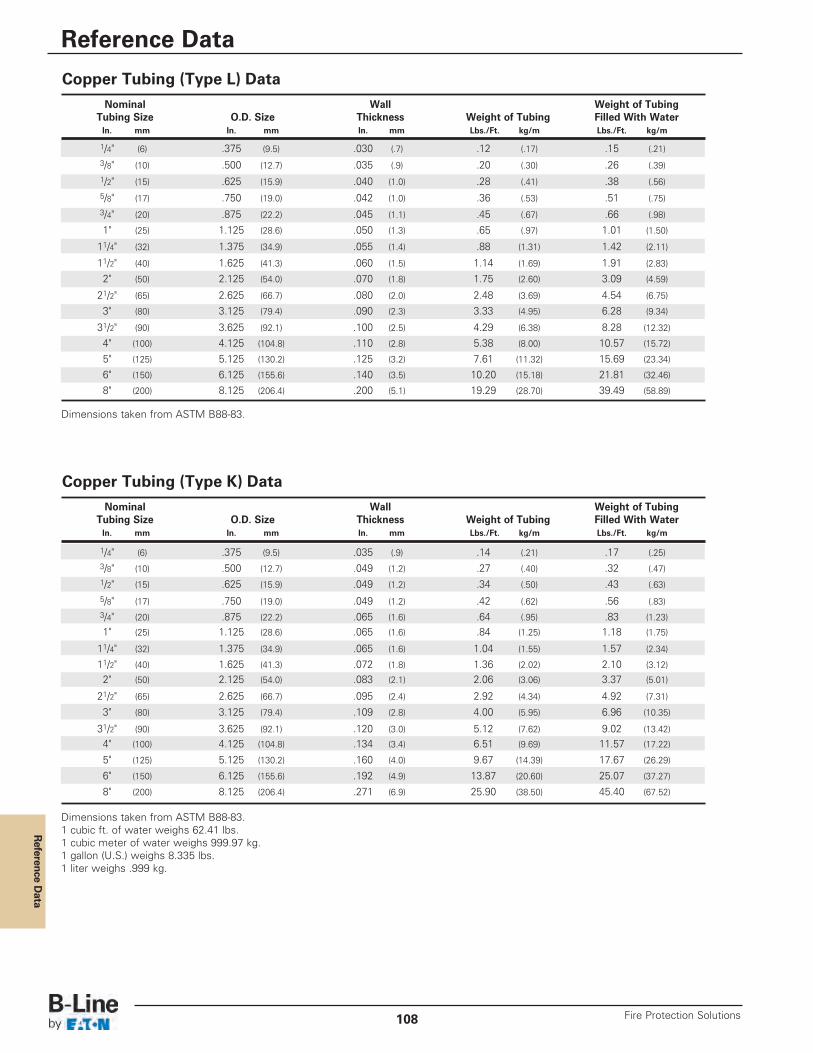
Reference D
ata
Copper Tubing (Type L) Data
Copper Tubing (Type K) Data
Dimensions taken from ASTM B88-83.
Dimensions taken from ASTM B88-83.1 cubic ft. of water weighs 62.41 lbs.1 cubic meter of water weighs 999.97 kg.1 gallon (U.S.) weighs 8.335 lbs.1 liter weighs .999 kg.
Nominal Wall Weight of TubingTubing Size O.D. Size Thickness Weight of Tubing Filled With WaterIn. mm In. mm In. mm Lbs./Ft. kg/m Lbs./Ft. kg/m
1/4" (6) .375 (9.5) .035 (.9) .14 (.21) .17 (.25)3/8" (10) .500 (12.7) .049 (1.2) .27 (.40) .32 (.47)1/2" (15) .625 (15.9) .049 (1.2) .34 (.50) .43 (.63)
5/8" (17) .750 (19.0) .049 (1.2) .42 (.62) .56 (.83)3/4" (20) .875 (22.2) .065 (1.6) .64 (.95) .83 (1.23)
1" (25) 1.125 (28.6) .065 (1.6) .84 (1.25) 1.18 (1.75)
11/4" (32) 1.375 (34.9) .065 (1.6) 1.04 (1.55) 1.57 (2.34)
11/2" (40) 1.625 (41.3) .072 (1.8) 1.36 (2.02) 2.10 (3.12)
2" (50) 2.125 (54.0) .083 (2.1) 2.06 (3.06) 3.37 (5.01)
21/2" (65) 2.625 (66.7) .095 (2.4) 2.92 (4.34) 4.92 (7.31)
3" (80) 3.125 (79.4) .109 (2.8) 4.00 (5.95) 6.96 (10.35)
31/2" (90) 3.625 (92.1) .120 (3.0) 5.12 (7.62) 9.02 (13.42)
4" (100) 4.125 (104.8) .134 (3.4) 6.51 (9.69) 11.57 (17.22)
5" (125) 5.125 (130.2) .160 (4.0) 9.67 (14.39) 17.67 (26.29)
6" (150) 6.125 (155.6) .192 (4.9) 13.87 (20.60) 25.07 (37.27)
8" (200) 8.125 (206.4) .271 (6.9) 25.90 (38.50) 45.40 (67.52)
Nominal Wall Weight of TubingTubing Size O.D. Size Thickness Weight of Tubing Filled With WaterIn. mm In. mm In. mm Lbs./Ft. kg/m Lbs./Ft. kg/m
1/4" (6) .375 (9.5) .030 (.7) .12 (.17) .15 (.21)3/8" (10) .500 (12.7) .035 (.9) .20 (.30) .26 (.39)1/2" (15) .625 (15.9) .040 (1.0) .28 (.41) .38 (.56)5/8" (17) .750 (19.0) .042 (1.0) .36 (.53) .51 (.75)3/4" (20) .875 (22.2) .045 (1.1) .45 (.67) .66 (.98)
1" (25) 1.125 (28.6) .050 (1.3) .65 (.97) 1.01 (1.50)
11/4" (32) 1.375 (34.9) .055 (1.4) .88 (1.31) 1.42 (2.11)
11/2" (40) 1.625 (41.3) .060 (1.5) 1.14 (1.69) 1.91 (2.83)
2" (50) 2.125 (54.0) .070 (1.8) 1.75 (2.60) 3.09 (4.59)
21/2" (65) 2.625 (66.7) .080 (2.0) 2.48 (3.69) 4.54 (6.75)
3" (80) 3.125 (79.4) .090 (2.3) 3.33 (4.95) 6.28 (9.34)
31/2" (90) 3.625 (92.1) .100 (2.5) 4.29 (6.38) 8.28 (12.32)
4" (100) 4.125 (104.8) .110 (2.8) 5.38 (8.00) 10.57 (15.72)
5" (125) 5.125 (130.2) .125 (3.2) 7.61 (11.32) 15.69 (23.34)
6" (150) 6.125 (155.6) .140 (3.5) 10.20 (15.18) 21.81 (32.46)
8" (200) 8.125 (206.4) .200 (5.1) 19.29 (28.70) 39.49 (58.89)
Reference Data
Fire Protection Solutions108
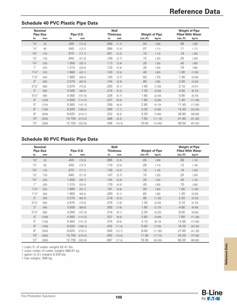
Reference Data
1 cubic ft. of water weighs 62.41 lbs.1 cubic meter of water weighs 999.97 kg.1 gallon (U.S.) weighs 8.335 lbs.1 liter weighs .999 kg.
Schedule 40 PVC Plastic Pipe Data
Schedule 80 PVC Plastic Pipe Data
Nominal Wall Weight of PipePipe Size Pipe O.D. Thickness Weight of Pipe Filled With WaterIn. mm In. mm In. mm Lbs./Ft. kg/m Lbs./Ft. kg/m
1/8" (3) .405 (10.3) .095 (2.4) .05 (.08) .06 (.10)
1/4" (6) .540 (13.7) .119 (3.0) .09 (.14) .12 (.18)
3/8" (10) .675 (17.1) .126 (3.2) .10 (.19) .16 (.28)1/2" (15) .840 (21.3) .147 (3.7) .10 (.20) .20 (.30)3/4" (20) 1.050 (26.7) .154 (3.9) .20 (.40) .40 (.70)
1" (25) 1.315 (33.4) .179 (4.5) .40 (.50) .70 (.90)
11/4" (32) 1.660 (42.1) .191 (4.8) .50 (.80) 1.00 (1.60)
11/2" (40) 1.900 (48.2) .200 (5.1) .60 (.90) 1.30 (2.00)
2" (50) 2.375 (60.3) .218 (5.5) .90 (1.30) 2.20 (3.20)
21/2" (65) 2.875 (73.0) .276 (7.0) 1.30 (2.00) 3.10 (4.70)
3" (80) 3.500 (88.9) .300 (7.6) 1.80 (2.70) 4.60 (6.90)
31/2" (90) 4.000 (101.6) .318 (8.1) 2.20 (3.20) 6.00 (8.90)
4" (100) 4.500 (114.3) .337 (8.5) 2.60 (3.90) 7.60 (11.30)
5" (125) 5.563 (141.3) .375 (9.5) 4.10 (6.10) 12.00 (17.80)
6" (150) 6.625 (168.3) .432 (11.0) 5.00 (7.50) 16.30 (24.30)
8" (200) 8.625 (219.1) .500 (12.7) 8.00 (11.90) 27.80 (41.30)
10" (250) 10.750 (273.0) .593 (15.0) 11.90 (17.70) 43.20 (77.60)
12" (300) 12.750 (323.8) .687 (17.4) 16.30 (24.30) 60.30 (89.80)
Nominal Wall Weight of PipePipe Size Pipe O.D. Thickness Weight of Pipe Filled With WaterIn. mm In. mm In. mm Lbs./Ft. kg/m Lbs./Ft. kg/m
1/8" (3) .405 (10.3) .068 (1.7) .04 (.06) .06 (.09)1/4" (6) .540 (13.7) .088 (2.2) .07 (.11) .11 (.17)3/8" (10) .675 (17.1) .091 (2.3) .10 (.14) .18 (.26)1/2" (15) .840 (21.3) .109 (2.7) .15 (.20) .25 (.40)3/4" (20) 1.050 (26.7) .113 (2.9) .20 (.30) .40 (.60)
1" (25) 1.315 (33.4) .133 (3.4) .30 (.40) .70 (.90)
11/4" (32) 1.660 (42.1) .140 (3.5) .40 (.60) 1.00 (1.50)
11/2" (40) 1.900 (48.2) .145 (3.7) .50 (.70) 1.40 (2.00)
2" (50) 2.375 (60.3) .154 (3.9) .60 (.90) 2.00 (3.00)
21/2" (65) 2.875 (73.0) .203 (5.1) 1.00 (1.50) 3.10 (4.51)
3" (80) 3.500 (88.9) .216 (5.5) 1.30 (2.00) 4.50 (6.70)
31/2" (90) 4.000 (101.6) .226 (5.7) 1.60 (2.40) 5.90 (8.70)
4" (100) 4.500 (114.3) .237 (6.0) 1.90 (2.80) 7.40 (11.00)
5" (125) 5.563 (141.3) .258 (6.5) 2.80 (4.10) 11.40 (17.00)
6" (150) 6.625 (168.3) .280 (7.1) 3.30 (4.90) 15.40 (23.00)
8" (200) 8.625 (219.1) .322 (8.2) 5.30 (7.80) 26.90 (39.90)
10" (250) 10.750 (273.0) .366 (9.3) 7.50 (11.10) 41.60 (61.80)
12" (300) 12.750 (323.8) .406 (10.3) 10.00 (14.90) 58.50 (87.00)
Reference Data
109Fire Protection Solutions
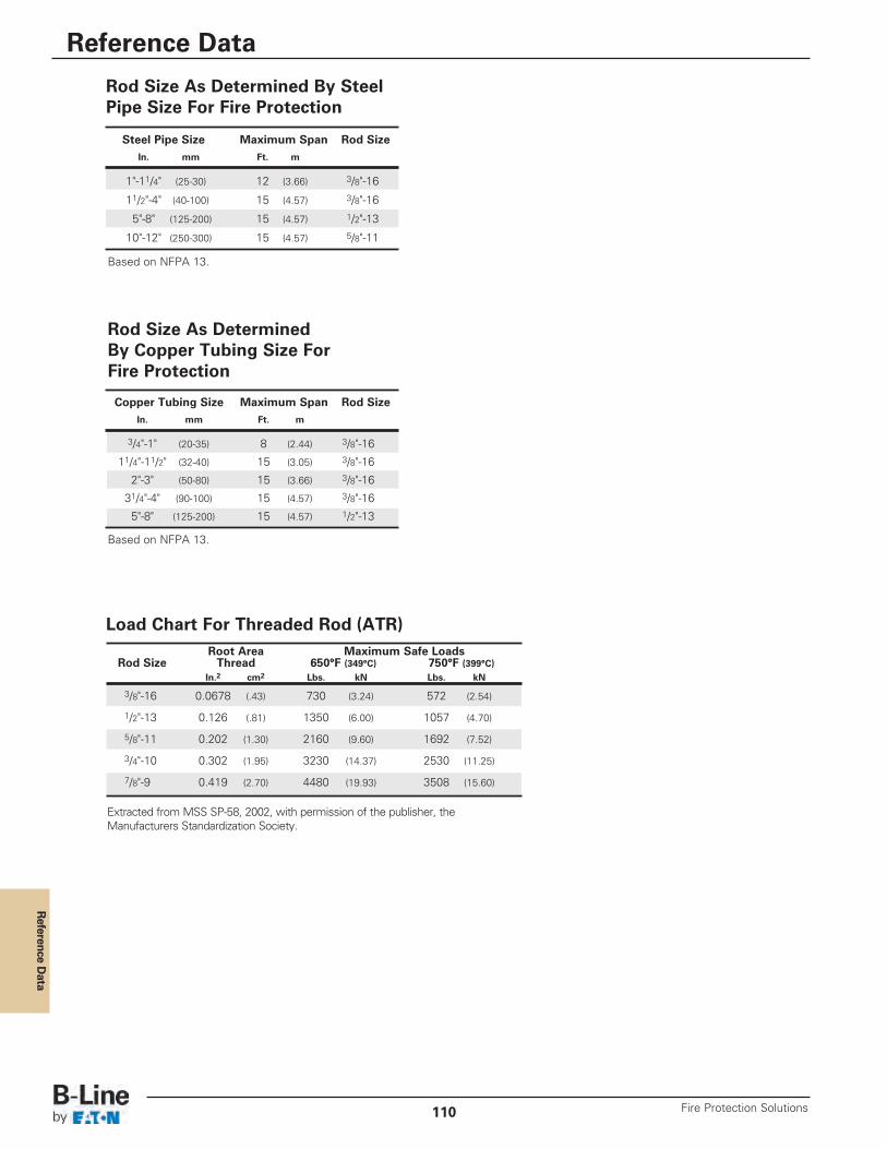
Reference D
ata
Based on NFPA 13.
Based on NFPA 13.
Extracted from MSS SP-58, 2002, with permission of the publisher, theManufacturers Standardization Society.
Root Area Maximum Safe LoadsRod Size Thread 650°F (349°C) 750°F (399°C)
In.2 cm2 Lbs. kN Lbs. kN
3/8"-16 0.0678 (.43) 730 (3.24) 572 (2.54)
1/2"-13 0.126 (.81) 1350 (6.00) 1057 (4.70)
5/8"-11 0.202 (1.30) 2160 (9.60) 1692 (7.52)
3/4"-10 0.302 (1.95) 3230 (14.37) 2530 (11.25)
7/8"-9 0.419 (2.70) 4480 (19.93) 3508 (15.60)
Steel Pipe Size Maximum Span Rod SizeIn. mm Ft. m
1"-11/4" (25-30) 12 (3.66) 3/8"-16
11/2"-4" (40-100) 15 (4.57) 3/8"-16
5"-8" (125-200) 15 (4.57) 1/2"-13
10"-12" (250-300) 15 (4.57) 5/8"-11
Copper Tubing Size Maximum Span Rod SizeIn. mm Ft. m
3/4"-1" (20-35) 8 (2.44) 3/8"-16
11/4"-11/2" (32-40) 15 (3.05) 3/8"-16
2"-3" (50-80) 15 (3.66) 3/8"-16
31/4"-4" (90-100) 15 (4.57) 3/8"-16
5"-8" (125-200) 15 (4.57) 1/2"-13
Rod Size As Determined By SteelPipe Size For Fire Protection
Rod Size As Determined By Copper Tubing Size For Fire Protection
Load Chart For Threaded Rod (ATR)
Reference Data
Fire Protection Solutions110
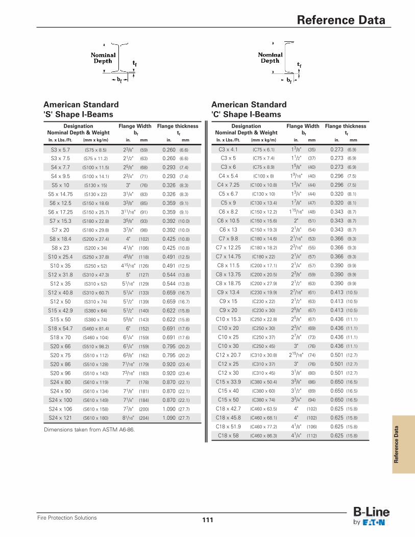
Reference Data
American Standard'S' Shape I-Beams
American Standard'C' Shape I-Beams
Dimensions taken from ASTM A6-86.
Designation Flange Width Flange thicknessNominal Depth & Weight bf tfIn. x Lbs./Ft. (mm x kg/m) in. mm in. mm
S3 x 5.7 (S75 x 8.5) 23/8" (59) 0.260 (6.6)
S3 x 7.5 (S75 x 11.2) 21/2" (63) 0.260 (6.6)
S4 x 7.7 (S100 x 11.5) 25/8" (68) 0.293 (7.4)
S4 x 9.5 (S100 x 14.1) 23/4" (71) 0.293 (7.4)
S5 x 10 (S130 x 15) 3" (76) 0.326 (8.3)
S5 x 14.75 (S130 x 22) 31/4" (83) 0.326 (8.3)
S6 x 12.5 (S150 x 18.6) 33/8" (85) 0.359 (9.1)
S6 x 17.25 (S150 x 25.7) 311/16" (91) 0.359 (9.1)
S7 x 15.3 (S180 x 22.8) 35/8" (93) 0.392 (10.0)
S7 x 20 (S180 x 29.8) 37/8" (98) 0.392 (10.0)
S8 x 18.4 (S200 x 27.4) 4" (102) 0.425 (10.8)
S8 x 23 (S200 x 34) 41/8" (106) 0.425 (10.8)
S10 x 25.4 (S250 x 37.8) 45/8" (118) 0.491 (12.5)
S10 x 35 (S250 x 52) 415/16" (126) 0.491 (12.5)
S12 x 31.8 (S310 x 47.3) 5" (127) 0.544 (13.8)
S12 x 35 (S310 x 52) 51/16" (129) 0.544 (13.8)
S12 x 40.8 (S310 x 60.7) 51/4" (133) 0.659 (16.7)
S12 x 50 (S310 x 74) 51/2" (139) 0.659 (16.7)
S15 x 42.9 (S380 x 64) 51/2" (140) 0.622 (15.8)
S15 x 50 (S380 x 74) 55/8" (143) 0.622 (15.8)
S18 x 54.7 (S460 x 81.4) 6" (152) 0.691 (17.6)
S18 x 70 (S460 x 104) 61/4" (159) 0.691 (17.6)
S20 x 66 (S510 x 98.2) 61/4" (159) 0.795 (20.2)
S20 x 75 (S510 x 112) 63/8" (162) 0.795 (20.2)
S20 x 86 (S510 x 128) 71/16" (179) 0.920 (23.4)
S20 x 96 (S510 x 143) 73/16" (183) 0.920 (23.4)
S24 x 80 (S610 x 119) 7" (178) 0.870 (22.1)
S24 x 90 (S610 x 134) 71/8" (181) 0.870 (22.1)
S24 x 100 (S610 x 149) 71/4" (184) 0.870 (22.1)
S24 x 106 (S610 x 158) 77/8" (200) 1.090 (27.7)
S24 x 121 (S610 x 180) 81/16" (204) 1.090 (27.7)
Designation Flange Width Flange thicknessNominal Depth & Weight bf tfIn. x Lbs./Ft. (mm x kg/m) in. mm in. mm
C3 x 4.1 (C75 x 6.1) 13/8" (35) 0.273 (6.9)
C3 x 5 (C75 x 7.4) 11/2" (37) 0.273 (6.9)
C3 x 6 (C75 x 8.9) 15/8" (40) 0.273 (6.9)
C4 x 5.4 (C100 x 8) 19/16" (40) 0.296 (7.5)
C4 x 7.25 (C100 x 10.8) 13/4" (44) 0.296 (7.5)
C5 x 6.7 (C130 x 10) 13/4" (44) 0.320 (8.1)
C5 x 9 (C130 x 13.4) 17/8" (47) 0.320 (8.1)
C6 x 8.2 (C150 x 12.2) 115/16" (48) 0.343 (8.7)
C6 x 10.5 (C150 x 15.6) 2" (51) 0.343 (8.7)
C6 x 13 (C150 x 19.3) 21/8" (54) 0.343 (8.7)
C7 x 9.8 (C180 x 14.6) 21/16" (53) 0.366 (9.3)
C7 x 12.25 (C180 x 18.2) 23/16" (55) 0.366 (9.3)
C7 x 14.75 (C180 x 22) 21/4" (57) 0.366 (9.3)
C8 x 11.5 (C200 x 17.1) 21/4" (57) 0.390 (9.9)
C8 x 13.75 (C200 x 20.5) 23/8" (59) 0.390 (9.9)
C8 x 18.75 (C200 x 27.9) 21/2" (63) 0.390 (9.9)
C9 x 13.4 (C230 x 19.9) 27/16" (61) 0.413 (10.5)
C9 x 15 (C230 x 22) 21/2" (63) 0.413 (10.5)
C9 x 20 (C230 x 30) 25/8" (67) 0.413 (10.5)
C10 x 15.3 (C250 x 22.8) 25/8" (67) 0.436 (11.1)
C10 x 20 (C250 x 30) 23/4" (69) 0.436 (11.1)
C10 x 25 (C250 x 37) 27/8" (73) 0.436 (11.1)
C10 x 30 (C250 x 45) 3" (76) 0.436 (11.1)
C12 x 20.7 (C310 x 30.8) 215/16" (74) 0.501 (12.7)
C12 x 25 (C310 x 37) 3" (76) 0.501 (12.7)
C12 x 30 (C310 x 45) 31/8" (80) 0.501 (12.7)
C15 x 33.9 (C380 x 50.4) 33/8" (86) 0.650 (16.5)
C15 x 40 (C380 x 60) 31/2" (89) 0.650 (16.5)
C15 x 50 (C380 x 74) 33/4" (94) 0.650 (16.5)
C18 x 42.7 (C460 x 63.5) 4" (102) 0.625 (15.8)
C18 x 45.8 (C460 x 68.1) 4" (102) 0.625 (15.8)
C18 x 51.9 (C460 x 77.2) 41/8" (106) 0.625 (15.8)
C18 x 58 (C460 x 86.3) 41/4" (112) 0.625 (15.8)
Reference Data
111Fire Protection Solutions
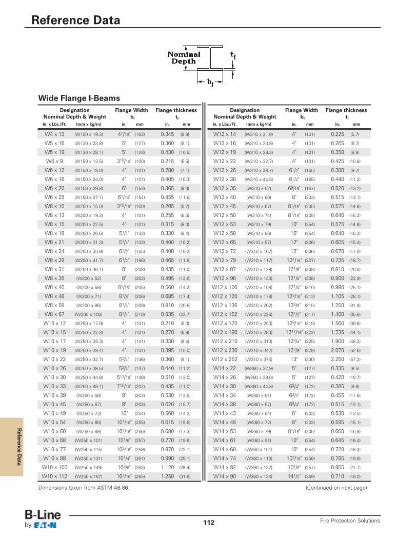
Reference D
ata
Dimensions taken from ASTM A6-86. (Continued on next page)
Wide Flange I-BeamsDesignation Flange Width Flange thickness
Nominal Depth & Weight bf tfIn. x Lbs./Ft. (mm x kg/m) in. mm in. mm
W4 x 13 (W100 x 19.3) 41/16" (103) 0.345 (8.8)
W5 x 16 (W130 x 23.8) 5" (127) 0.360 (9.1)
W5 x 19 (W130 x 28.1) 5" (128) 0.430 (10.9)
W6 x 9 (W150 x 13.5) 315/16" (100) 0.215 (5.5)
W6 x 12 (W150 x 18.0) 4" (101) 0.280 (7.1)
W6 x 16 (W150 x 24.0) 4" (101) 0.405 (10.3)
W6 x 20 (W150 x 29.8) 6" (153) 0.365 (9.3)
W6 x 25 (W150 x 37.1) 61/16" (154) 0.455 (11.6)
W8 x 10 (W200 x 15.0) 315/16" (100) 0.205 (5.2)
W8 x 13 (W200 x 19.3) 4" (101) 0.255 (6.5)
W8 x 15 (W200 x 22.5) 4" (101) 0.315 (8.0)
W8 x 18 (W200 x 26.6) 51/4" (133) 0.330 (8.4)
W8 x 21 (W200 x 31.3) 51/4" (133) 0.400 (10.2)
W8 x 24 (W200 x 35.9) 61/2" (165) 0.400 (10.2)
W8 x 28 (W200 x 41.7) 61/2" (166) 0.465 (11.8)
W8 x 31 (W200 x 46.1) 8" (203) 0.435 (11.0)
W8 x 35 (W200 x 52) 8" (203) 0.495 (12.6)
W8 x 40 (W200 x 59) 81/16" (205) 0.560 (14.2)
W8 x 48 (W200 x 71) 81/8" (206) 0.685 (17.4)
W8 x 58 (W200 x 86) 81/4" (209) 0.810 (20.6)
W8 x 67 (W200 x 100) 81/4" (210) 0.935 (23.7)
W10 x 12 (W250 x 17.9) 4" (101) 0.210 (5.3)
W10 x 15 (W250 x 22.3) 4" (101) 0.270 (6.9)
W10 x 17 (W250 x 25.3) 4" (101) 0.330 (8.4)
W10 x 19 (W250 x 28.4) 4" (101) 0.395 (10.0)
W10 x 22 (W250 x 32.7) 53/4" (146) 0.360 (9.1)
W10 x 26 (W250 x 38.5) 53/4" (147) 0.440 (11.2)
W10 x 30 (W250 x 44.8) 513/16" (148) 0.510 (13.0)
W10 x 33 (W250 x 49.1) 715/16" (202) 0.435 (11.0)
W10 x 39 (W250 x 58) 8" (203) 0.530 (13.5)
W10 x 45 (W250 x 67) 8" (203) 0.620 (15.7)
W10 x 49 (W250 x 73) 10" (254) 0.560 (14.2)
W10 x 54 (W250 x 80) 101/16" (255) 0.615 (15.6)
W10 x 60 (W250 x 89) 101/16" (256) 0.680 (17.3)
W10 x 68 (W250 x 101) 101/8" (257) 0.770 (19.6)
W10 x 77 (W250 x 115) 103/16" (259) 0.870 (22.1)
W10 x 88 (W250 x 131) 101/4" (261) 0.990 (25.1)
W10 x 100 (W250 x 149) 103/8" (263) 1.120 (28.4)
W10 x 112 (W250 x 167) 107/16" (265) 1.250 (31.8)
Designation Flange Width Flange thicknessNominal Depth & Weight bf tfIn. x Lbs./Ft. (mm x kg/m) in. mm in. mm
W12 x 14 (W310 x 21.0) 4" (101) 0.225 (5.7)
W12 x 16 (W310 x 23.8) 4" (101) 0.265 (6.7)
W12 x 19 (W310 x 28.3) 4" (101) 0.350 (8.9)
W12 x 22 (W310 x 32.7) 4" (101) 0.425 (10.8)
W12 x 26 (W310 x 38.7) 61/2" (165) 0.380 (9.7)
W12 x 30 (W310 x 44.5) 61/2" (165) 0.440 (11.2)
W12 x 35 (W310 x 52) 69/16" (167) 0.520 (13.2)
W12 x 40 (W310 x 60) 8" (203) 0.515 (13.1)
W12 x 45 (W310 x 67) 81/16" (205) 0.575 (14.6)
W12 x 50 (W310 x 74) 81/16" (205) 0.640 (16.3)
W12 x 53 (W310 x 79) 10" (254) 0.575 (14.6)
W12 x 58 (W310 x 86) 10" (254) 0.640 (16.3)
W12 x 65 (W310 x 97) 12" (306) 0.605 (15.4)
W12 x 72 (W310 x 107) 12" (306) 0.670 (17.0)
W12 x 79 (W310 x 117) 121/16" (307) 0.735 (18.7)
W12 x 87 (W310 x 129) 121/8" (308) 0.810 (20.6)
W12 x 96 (W310 x 143) 121/8" (308) 0.900 (22.9)
W12 x 106 (W310 x 158) 121/4" (310) 0.990 (25.1)
W12 x 120 (W310 x 179) 125/16" (313) 1.105 (28.1)
W12 x 136 (W310 x 202) 123/8" (315) 1.250 (31.8)
W12 x 152 (W310 x 226) 121/2" (317) 1.400 (35.6)
W12 x 170 (W310 x 253) 129/16" (319) 1.560 (39.6)
W12 x 190 (W310 x 283) 1211/16" (322) 1.735 (44.1)
W12 x 210 (W310 x 313) 123/4" (325) 1.900 (48.3)
W12 x 230 (W310 x 342) 127/8" (328) 2.070 (52.6)
W12 x 252 (W310 x 375) 13" (330) 2.250 (57.2)
W14 x 22 (W360 x 32.9) 5" (127) 0.335 (8.5)
W14 x 26 (W360 x 39.0) 5" (127) 0.420 (10.7)
W14 x 30 (W360 x 44.8) 63/4" (172) 0.385 (9.8)
W14 x 34 (W360 x 51) 63/4" (172) 0.455 (11.6)
W14 x 38 (W360 x 57) 63/4" (172) 0.515 (13.1)
W14 x 43 (W360 x 64) 8" (203) 0.530 (13.5)
W14 x 48 (W360 x 72) 8" (203) 0.595 (15.1)
W14 x 53 (W360 x 79) 81/16" (205) 0.660 (16.8)
W14 x 61 (W360 x 91) 10" (254) 0.645 (16.4)
W14 x 68 (W360 x 101) 10" (254) 0.720 (18.3)
W14 x 74 (W360 x 110) 101/16" (256) 0.785 (19.9)
W14 x 82 (W360 x 122) 101/8" (257) 0.855 (21.7)
W14 x 90 (W360 x 134) 141/2" (369) 0.710 (18.0)
Reference Data
Fire Protection Solutions112
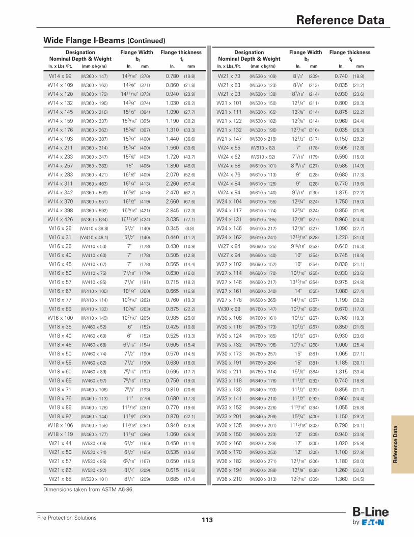
Reference Data
Wide Flange I-Beams (Continued)
Dimensions taken from ASTM A6-86.
Designation Flange Width Flange thicknessNominal Depth & Weight bf tfIn. x Lbs./Ft. (mm x kg/m) In. mm In. mm
W14 x 99 (W360 x 147) 149/16" (370) 0.780 (19.8)
W14 x 109 (W360 x 162) 145/8" (371) 0.860 (21.8)
W14 x 120 (W360 x 179) 1411/16" (373) 0.940 (23.9)
W14 x 132 (W360 x 196) 143/4" (374) 1.030 (26.2)
W14 x 145 (W360 x 216) 151/2" (394) 1.090 (27.7)
W14 x 159 (W360 x 237) 159/16" (395) 1.190 (30.2)
W14 x 176 (W360 x 262) 155/8" (397) 1.310 (33.3)
W14 x 193 (W360 x 287) 153/4" (400) 1.440 (36.6)
W14 x 211 (W360 x 314) 153/4" (400) 1.560 (39.6)
W14 x 233 (W360 x 347) 157/8" (403) 1.720 (43.7)
W14 x 257 (W360 x 382) 16" (406) 1.890 (48.0)
W14 x 283 (W360 x 421) 161/8" (409) 2.070 (52.6)
W14 x 311 (W360 x 463) 161/4" (413) 2.260 (57.4)
W14 x 342 (W360 x 509) 163/8" (416) 2.470 (62.7)
W14 x 370 (W360 x 551) 161/2" (419) 2.660 (67.6)
W14 x 398 (W360 x 592) 169/16" (421) 2.845 (72.3)
W14 x 426 (W360 x 634) 1611/16" (424) 3.035 (77.1)
W16 x 26 (W410 x 38.8) 51/2" (140) 0.345 (8.8)
W16 x 31 (W410 x 46.1) 51/2" (140) 0.440 (11.2)
W16 x 36 (W410 x 53) 7" (178) 0.430 (10.9)
W16 x 40 (W410 x 60) 7" (178) 0.505 (12.8)
W16 x 45 (W410 x 67) 7" (178) 0.565 (14.4)
W16 x 50 (W410 x 75) 71/16" (179) 0.630 (16.0)
W16 x 57 (W410 x 85) 71/8" (181) 0.715 (18.2)
W16 x 67 (W410 x 100) 101/4" (260) 0.665 (16.9)
W16 x 77 (W410 x 114) 105/16" (262) 0.760 (19.3)
W16 x 89 (W410 x 132) 103/8" (263) 0.875 (22.2)
W16 x 100 (W410 x 149) 107/16" (265) 0.985 (25.0)
W18 x 35 (W460 x 52) 6" (152) 0.425 (10.8)
W18 x 40 (W460 x 60) 6" (152) 0.525 (13.3)
W18 x 46 (W460 x 68) 61/16" (154) 0.605 (15.4)
W18 x 50 (W460 x 74) 71/2" (190) 0.570 (14.5)
W18 x 55 (W460 x 82) 71/2" (190) 0.630 (16.0)
W18 x 60 (W460 x 89) 79/16" (192) 0.695 (17.7)
W18 x 65 (W460 x 97) 79/16" (192) 0.750 (19.0)
W18 x 71 (W460 x 106) 75/8" (193) 0.810 (20.6)
W18 x 76 (W460 x 113) 11" (279) 0.680 (17.3)
W18 x 86 (W460 x 128) 111/16" (281) 0.770 (19.6)
W18 x 97 (W460 x 144) 111/8" (282) 0.870 (22.1)
W18 x 106 (W460 x 158) 113/16" (284) 0.940 (23.9)
W18 x 119 (W460 x 177) 111/4" (286) 1.060 (26.9)
W21 x 44 (W530 x 66) 61/2" (165) 0.450 (11.4)
W21 x 50 (W530 x 74) 61/2" (165) 0.535 (13.6)
W21 x 57 (W530 x 85) 69/16" (167) 0.650 (16.5)
W21 x 62 (W530 x 92) 81/4" (209) 0.615 (15.6)
W21 x 68 (W530 x 101) 81/4" (209) 0.685 (17.4)
Designation Flange Width Flange thicknessNominal Depth & Weight bf tfIn. x Lbs./Ft. (mm x kg/m) In. mm In. mm
W21 x 73 (W530 x 109) 81/4" (209) 0.740 (18.8)
W21 x 83 (W530 x 123) 87/8" (213) 0.835 (21.2)
W21 x 93 (W530 x 138) 87/16" (214) 0.930 (23.6)
W21 x 101 (W530 x 150) 121/4" (311) 0.800 (20.3)
W21 x 111 (W530 x 165) 123/8" (314) 0.875 (22.2)
W21 x 122 (W530 x 182) 123/8" (314) 0.960 (24.4)
W21 x 132 (W530 x 196) 127/16" (316) 0.035 (26.3)
W21 x 147 (W530 x 219) 121/2" (317) 0.150 (29.2)
W24 x 55 (W610 x 82) 7" (178) 0.505 (12.8)
W24 x 62 (W610 x 92) 71/16" (179) 0.590 (15.0)
W24 x 68 (W610 x 101) 815/16" (227) 0.585 (14.9)
W24 x 76 (W610 x 113) 9" (228) 0.680 (17.3)
W24 x 84 (W610 x 125) 9" (228) 0.770 (19.6)
W24 x 94 (W610 x 140) 91/16" (230) 1.875 (22.2)
W24 x 104 (W610 x 155) 123/4" (324) 1.750 (19.0)
W24 x 117 (W610 x 174) 123/4" (324) 0.850 (21.6)
W24 x 131 (W610 x 195) 127/8" (327) 0.960 (24.4)
W24 x 146 (W610 x 217) 127/8" (327) 1.090 (27.7)
W24 x 162 (W610 x 241) 1215/16" (328) 1.220 (31.0)
W27 x 84 (W690 x 125) 915/16" (252) 0.640 (16.3)
W27 x 94 (W690 x 140) 10" (254) 0.745 (18.9)
W27 x 102 (W690 x 152) 10" (254) 0.830 (21.1)
W27 x 114 (W690 x 170) 101/16" (255) 0.930 (23.6)
W27 x 146 (W690 x 217) 1315/16" (354) 0.975 (24.8)
W27 x 161 (W690 x 240) 14" (355) 1.080 (27.4)
W27 x 178 (W690 x 265) 141/16" (357) 1.190 (30.2)
W30 x 99 (W760 x 147) 107/16" (265) 0.670 (17.0)
W30 x 108 (W760 x 161) 101/2" (267) 0.760 (19.3)
W30 x 116 (W760 x 173) 101/2" (267) 0.850 (21.6)
W30 x 124 (W760 x 185) 101/2" (267) 0.930 (23.6)
W30 x 132 (W760 x 196) 109/16" (268) 1.000 (25.4)
W30 x 173 (W760 x 257) 15" (381) 1.065 (27.1)
W30 x 191 (W760 x 284) 15" (381) 1.185 (30.1)
W30 x 211 (W760 x 314) 151/8" (384) 1.315 (33.4)
W33 x 118 (W840 x 176) 111/2" (292) 0.740 (18.8)
W33 x 130 (W840 x 193) 111/2" (292) 0.855 (21.7)
W33 x 141 (W840 x 210) 111/2" (292) 0.960 (24.4)
W33 x 152 (W840 x 226) 119/16" (294) 1.055 (26.8)
W33 x 201 (W840 x 299) 153/4" (400) 1.150 (29.2)
W36 x 135 (W920 x 201) 1115/16" (303) 0.790 (20.1)
W36 x 150 (W920 x 223) 12" (305) 0.940 (23.9)
W36 x 160 (W920 x 238) 12" (305) 1.020 (25.9)
W36 x 170 (W920 x 253) 12" (305) 1.100 (27.9)
W36 x 182 (W920 x 271) 121/16" (306) 1.180 (30.0)
W36 x 194 (W920 x 289) 121/8" (308) 1.260 (32.0)
W36 x 210 (W920 x 313) 123/16" (309) 1.360 (34.5)
Reference Data
113Fire Protection Solutions
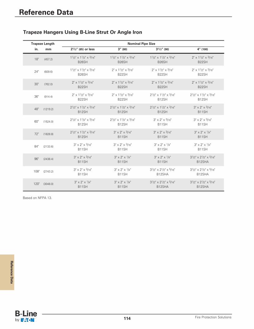
Reference D
ata
Reference Data
Fire Protection Solutions114
Based on NFPA 13.
Trapeze Hangers Using B-Line Strut Or Angle Iron
Trapeze Length Nominal Pipe Size
in. mm 21/2" (65) or less 3" (80) 31/2" (90) 4" (100)
18" (457.2) 11/2" x 11/2" x 3/16" 11/2" x 11/2" x 3/16" 11/2" x 11/2" x 3/16" 2" x 11/2" x 3/16"B26SH B26SH B26SH B22SH
24" (609.6) 11/2" x 11/2" x 3/16" 2" x 11/2" x 3/16" 2" x 11/2" x 3/16" 2" x 11/2" x 3/16"B26SH B22SH B22SH B22SH
30" (762.0) 2" x 11/2" x 3/16" 2" x 11/2" x 3/16" 2" x 11/2" x 3/16" 2" x 11/2" x 3/16"B22SH B22SH B22SH B22SH
36" (914.4) 2" x 11/2" x 3/16" 2" x 11/2" x 3/16" 21/2" x 11/2" x 3/16" 21/2" x 11/2" x 3/16"B22SH B22SH B12SH B12SH
48" (1219.2) 21/2" x 11/2" x 3/16" 21/2" x 11/2" x 3/16" 21/2" x 11/2" x 3/16" 3" x 2" x 3/16"B12SH B12SH B12SH B11SH
60" (1524.0) 21/2" x 11/2" x 3/16" 21/2" x 11/2" x 3/16" 3" x 2" x 3/16" 3" x 2" x 3/16"B12SH B12SH B11SH B11SH
72" (1828.8) 21/2" x 11/2" x 3/16" 3" x 2" x 3/16" 3" x 2" x 3/16" 3" x 2" x 1/4"B12SH B11SH B11SH B11SH
84" (2133.6) 3" x 2" x 3/16" 3" x 2" x 3/16" 3" x 2" x 1/4" 3" x 2" x 1/4"B11SH B11SH B11SH B11SH
96" (2438.4) 3" x 2" x 3/16" 3" x 2" x 1/4" 3" x 2" x 1/4" 31/2" x 21/2" x 5/16"B11SH B11SH B11SH B12SHA
108" (2743.2) 3" x 2" x 3/16" 3" x 2" x 1/4" 31/2" x 21/2" x 5/16" 31/2" x 21/2" x 5/16"B11SH B11SH B12SHA B12SHA
120" (3048.0) 3" x 2" x 1/4" 3" x 2" x 1/4" 31/2" x 21/2" x 5/16" 31/2" x 21/2" x 5/16"B11SH B11SH B12SHA B12SHA
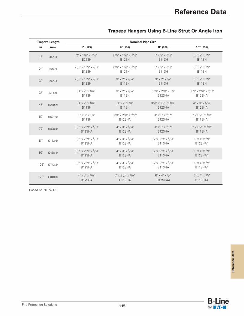
Reference Data
Reference Data
115Fire Protection Solutions
Based on NFPA 13.
Trapeze Length Nominal Pipe Size
in. mm 5" (125) 6" (150) 8" (200) 10" (250)
18" (457.2) 2" x 11/2" x 3/16" 21/2" x 11/2" x 3/16" 3" x 2" x 3/16" 3" x 2" x 1/4"B22SH B12SH B11SH B11SH
24" (609.6) 21/2" x 11/2" x 3/16" 21/2" x 11/2" x 3/16" 3" x 2" x 3/16" 3" x 2" x 1/4"B12SH B12SH B11SH B11SH
30" (762.0) 21/2" x 11/2" x 3/16" 3" x 2" x 3/16" 3" x 2" x 1/4" 3" x 2" x 1/4"B12SH B11SH B11SH B11SH
36" (914.4) 3" x 2" x 3/16" 3" x 2" x 3/16" 31/2" x 21/2" x 1/4" 31/2" x 21/2" x 5/16"B11SH B11SH B12SHA B12SHA
48" (1219.2) 3" x 2" x 3/16" 3" x 2" x 1/4" 31/2" x 21/2" x 5/16" 4" x 3" x 5/16"B11SH B11SH B12SHA B12SHA
60" (1524.0) 3" x 2" x 1/4" 31/2" x 21/2" x 5/16" 4" x 3" x 5/16" 5" x 31/2" x 5/16"B11SH B12SHA B12SHA B11SHA
72" (1828.8) 31/2" x 21/2" x 5/16" 4" x 3" x 5/16" 4" x 3" x 5/16" 5" x 31/2" x 5/16"B12SHA B12SHA B12SHA B11SHA
84" (2133.6) 31/2" x 21/2" x 5/16" 4" x 3" x 5/16" 5" x 31/2" x 5/16" 6" x 4" x 1/4"B12SHA B12SHA B11SHA B12SHA4
96" (2438.4) 31/2" x 21/2" x 5/16" 4" x 3" x 5/16" 5" x 31/2" x 5/16" 6" x 4" x 1/4"B12SHA B12SHA B11SHA B12SHA4
108" (2743.2) 31/2" x 21/2" x 5/16" 4" x 3" x 5/16" 5" x 31/2" x 5/16" 6" x 4" x 3/8"B12SHA B12SHA B11SHA B11SHA4
120" (3048.0) 4" x 3" x 5/16" 5" x 31/2" x 5/16" 6" x 4" x 1/4" 6" x 4" x 3/8"B12SHA B11SHA B12SHA4 B11SHA4
Trapeze Hangers Using B-Line Strut Or Angle Iron
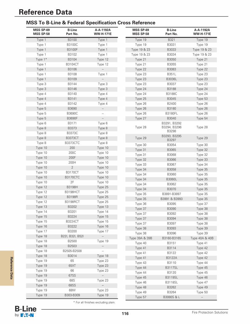
Reference D
ata
Reference Data
Fire Protection Solutions116
MSS SP-69 B-Line A-A-1192AMSS SP-58 Part No. WW-H-171E
Type 1 B3100 Type 1Type 1 B3100C Type 1Type 1 B3100F Type 1Type 1 B3102 Type 1Type 1* B3104 Type 12Type 1 B3104CT Type 12Type 1 B3106 --Type 1 B3108 Type 1Type 1 B3109 --Type 3 B3144 Type 3Type 3 B3146 Type 3Type 4 B3140 Type 4Type 4 B3141 Type 4Type 4 B3142 Type 4Type 5 B3690 --Type 5 B3690C --Type 5 B3690F --Type 6 B3171 Type 6Type 8 B3373 Type 8Type 8 B3373C Type 8Type 8 B3373CT Type 8Type 8 B3373CTC Type 8Type 10 200 Type 10Type 10 200C Type 10Type 10 200F Type 10Type 10 200H Type 10Type 10 2 Type 10Type 10 B3170CT Type 10Type 10 B3170CTC Type 10Type 10 2F Type 10Type 12 B3198H Type 25Type 12 B3198HCT Type 25Type 12 B3198R Type 25Type 12 B3198RCT Type 25Type 13 B3202 Type 13Type 14 B3201 Type 14Type 15 B3224 Type 15Type 15 B3224CT Type 15Type 16 B3222 Type 16Type 17 B3200 Type 17Type 18 B22I, B32I, B52I --Type 18 B2500 Type 19Type 18 B2503 --Type 18 B2505-B2508 --Type 18 B3014 Type 18Type 19 65 Type 23Type 19 65XT Type 23Type 19 66 Type 23Type 19 67SS --Type 19 68S Type 23Type 19 68SS --Type 19 68W Type 23Type 19 B303-B309 Type 19
MSS SP-69 B-Line A-A-1192AMSS SP-58 Part No. WW-H-171E
Type 19 B321 Type 19Type 19 B3031 Type 19
Type 19 & 23 B3033 Type 19 & 23Type 19 & 23 B3034 Type 19 & 23
Type 21 B3050 Type 21Type 21 B3055 Type 21Type 22 B3083 Type 22Type 23 B351L Type 23Type 23 B3036L Type 23Type 23 B3037 Type 23Type 24 B3188 Type 24Type 24 B3188C Type 24Type 25 B3045 Type 53Type 26 B2400 Type 26Type 26 B3180 Type 26Type 26 B3180FL Type 26Type 27 B3040 Type 54
B3291, B3292Type 28 B3294, B3296 Type 28
B3298
Type 29B3293, B3295
Type 29B3297Type 30 B3054 Type 30Type 31 B3065 Type 32Type 31 B3068 Type 32Type 32 B3066 Type 33Type 33 B3067 Type 34Type 34 B3058 Type 35Type 34 B3060 Type 35Type 34 B3060L Type 35Type 34 B3062 Type 35Type 34 B3070 Type 35Type 35 B3891-B3897 Type 35Type 35 B3991 & B3993 Type 35Type 36 B3095 Type 37Type 37 B3090 Type 38Type 37 B3092 Type 38Type 37 B3094 Type 38Type 37 B3097 Type 38Type 38 B3093 Type 39Type 38 B3096 Type 39
Type 39A & 39B B3160-B3165 Type 40A & 40BType 40 B3151 Type 41Type 41 B3114 Type 42Type 41 B3122 Type 42Type 41 B3122A Type 42Type 43 B3110 Type 44Type 44 B3117SL Type 45Type 44 B3120 Type 45Type 45 B3119SL Type 46Type 46 B3118SL Type 47Type 48 B3262 Type 49Type 49 B3264 Type 50Type 57 B3080S & L --
MSS To B-Line & Federal Specification Cross Reference
* For all finishes excluding plain.
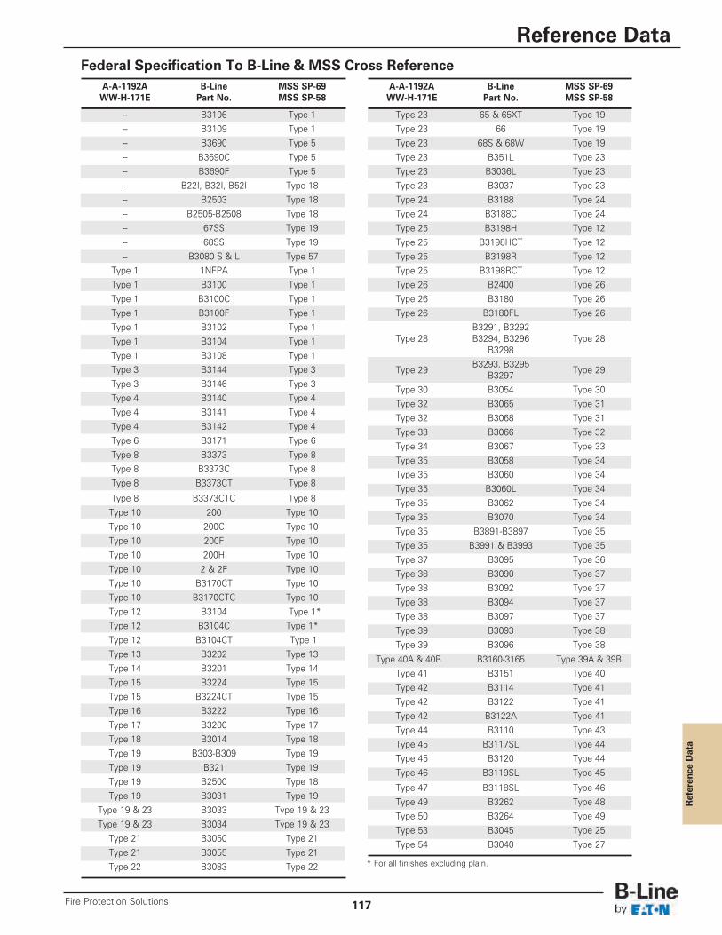
Reference Data
Reference Data
117Fire Protection Solutions
Federal Specification To B-Line & MSS Cross ReferenceA-A-1192A B-Line MSS SP-69WW-H-171E Part No. MSS SP-58
-- B3106 Type 1-- B3109 Type 1-- B3690 Type 5-- B3690C Type 5-- B3690F Type 5-- B22I, B32I, B52I Type 18-- B2503 Type 18-- B2505-B2508 Type 18-- 67SS Type 19-- 68SS Type 19-- B3080 S & L Type 57
Type 1 1NFPA Type 1Type 1 B3100 Type 1Type 1 B3100C Type 1Type 1 B3100F Type 1Type 1 B3102 Type 1Type 1 B3104 Type 1Type 1 B3108 Type 1Type 3 B3144 Type 3Type 3 B3146 Type 3Type 4 B3140 Type 4Type 4 B3141 Type 4Type 4 B3142 Type 4Type 6 B3171 Type 6Type 8 B3373 Type 8Type 8 B3373C Type 8Type 8 B3373CT Type 8
Type 8 B3373CTC Type 8Type 10 200 Type 10Type 10 200C Type 10Type 10 200F Type 10Type 10 200H Type 10Type 10 2 & 2F Type 10Type 10 B3170CT Type 10Type 10 B3170CTC Type 10Type 12 B3104 Type 1*Type 12 B3104C Type 1*Type 12 B3104CT Type 1Type 13 B3202 Type 13Type 14 B3201 Type 14Type 15 B3224 Type 15Type 15 B3224CT Type 15Type 16 B3222 Type 16Type 17 B3200 Type 17Type 18 B3014 Type 18Type 19 B303-B309 Type 19Type 19 B321 Type 19Type 19 B2500 Type 18Type 19 B3031 Type 19
Type 19 & 23 B3033 Type 19 & 23Type 19 & 23 B3034 Type 19 & 23
Type 21 B3050 Type 21Type 21 B3055 Type 21Type 22 B3083 Type 22
A-A-1192A B-Line MSS SP-69WW-H-171E Part No. MSS SP-58
Type 23 65 & 65XT Type 19Type 23 66 Type 19Type 23 68S & 68W Type 19Type 23 B351L Type 23Type 23 B3036L Type 23Type 23 B3037 Type 23Type 24 B3188 Type 24Type 24 B3188C Type 24Type 25 B3198H Type 12Type 25 B3198HCT Type 12Type 25 B3198R Type 12Type 25 B3198RCT Type 12Type 26 B2400 Type 26Type 26 B3180 Type 26Type 26 B3180FL Type 26
B3291, B3292Type 28 B3294, B3296 Type 28
B3298
Type 29B3293, B3295
Type 29B3297Type 30 B3054 Type 30Type 32 B3065 Type 31Type 32 B3068 Type 31Type 33 B3066 Type 32Type 34 B3067 Type 33Type 35 B3058 Type 34Type 35 B3060 Type 34Type 35 B3060L Type 34Type 35 B3062 Type 34Type 35 B3070 Type 34Type 35 B3891-B3897 Type 35Type 35 B3991 & B3993 Type 35Type 37 B3095 Type 36Type 38 B3090 Type 37Type 38 B3092 Type 37Type 38 B3094 Type 37Type 38 B3097 Type 37Type 39 B3093 Type 38Type 39 B3096 Type 38
Type 40A & 40B B3160-3165 Type 39A & 39BType 41 B3151 Type 40Type 42 B3114 Type 41Type 42 B3122 Type 41Type 42 B3122A Type 41Type 44 B3110 Type 43Type 45 B3117SL Type 44Type 45 B3120 Type 44Type 46 B3119SL Type 45
Type 47 B3118SL Type 46Type 49 B3262 Type 48Type 50 B3264 Type 49Type 53 B3045 Type 25Type 54 B3040 Type 27
* For all finishes excluding plain.
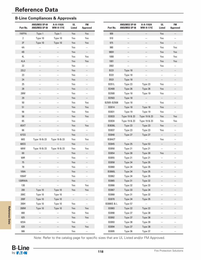
Reference D
ata
Reference Data
Fire Protection Solutions118
B-Line CompIiances & Approvals
1NFPA Type 1 Type 1 Yes Yes
2 Type 10 Type 10 Yes Yes
2F Type 10 Type 10 Yes Yes
4A -- -- Yes --
4B -- -- Yes --
4L -- -- Yes Yes
4LA -- -- Yes Yes
22 -- -- Yes --
22L2 -- -- Yes --
23 -- -- Yes --
24 -- -- Yes --
25 -- -- Yes --
28 -- -- Yes --
28M -- -- Yes --
29 -- -- Yes --
50 -- -- Yes Yes
51 -- -- Yes Yes
56 -- -- Yes Yes
58 -- -- Yes Yes
65 -- -- Yes --
65XT -- -- Yes Yes
66 -- -- Yes --
67SS -- -- Yes --
68S Type 19 & 23 Type 19 & 23 Yes Yes
68SS -- -- Yes --
68W Type 19 & 23 Type 19 & 23 Yes Yes
69 -- -- Yes --
69R -- -- Yes --
75 -- -- Yes --
78 -- -- Yes --
109A -- -- Yes --
109AF -- -- Yes --
120RWA -- -- Yes --
130 -- -- Yes Yes
200 Type 10 Type 10 Yes Yes
200C Type 10 Type 10 -- --
200F Type 10 Type 10 -- --
200H Type 10 Type 10 Yes --
200M Type 10 Type 10 Yes Yes
800 -- -- Yes Yes
825 -- -- Yes Yes
825A -- -- Yes --
828 -- -- Yes Yes
906 -- -- Yes --
909 -- -- Yes --
910 -- -- Yes --
975 -- -- Yes --
980 -- -- Yes Yes
980H -- -- Yes Yes
1000 -- -- Yes Yes
1001 -- -- Yes Yes
2002 -- -- Yes --
B22I Type 18 -- -- --
B32I Type 18 -- -- --
B52I Type 18 -- -- --
B351L Type 23 Type 23 Yes --
B2400 Type 26 Type 26 Yes --
B2500 Type 18 Type 19 Yes --
B2503 Type 18 -- -- --
B2505-B2508 Type 18 -- Yes --
B3014 Type 18 Type 18 Yes --
B3031 Type 19 Type 19 Yes --
B3033 Type 19 & 23 Type 19 & 23 Yes Yes
B3034 Type 19 & 23 Type 19 & 23 Yes Yes
B3036L Type 23 Type 23 Yes --
B3037 Type 23 Type 23 Yes --
B3040 Type 27 Type 27 -- --
B3042T -- -- Yes --
B3045 Type 25 Type 53 -- --
B3050 Type 21 Type 21 -- --
B3054 Type 30 Type 30 Yes --
B3055 Type 21 Type 21 -- --
B3058 Type 34 Type 35 -- --
B3060 Type 34 Type 35 -- --
B3060L Type 34 Type 35 -- --
B3062 Type 34 Type 35 -- --
B3065 Type 31 Type 32 -- --
B3066 Type 32 Type 33 -- --
B3067 Type 33 Type 34 -- --
B3068 Type 31 Type 32 -- --
B3070 Type 34 Type 35 -- --
B3080S & L Type 57 -- -- --
B3083 Type 22 Type 22 -- --
B3090 Type 37 Type 38 -- --
B3092 Type 37 Type 38 -- --
B3093 Type 38 Type 39 -- --
B3094 Type 37 Type 38 -- --
B3095 Type 36 Type 37 -- --
ANSI/MSS SP-69 A-A-1192A UL FMPart No. ANSI/MSS SP-58 WW-H-171E Listed Approved
ANSI/MSS SP-69 A-A-1192A UL FMPart No. ANSI/MSS SP-58 WW-H-171E Listed Approved
Note: Refer to the catalog page for specific sizes that are UL Listed and/or FM Approved.
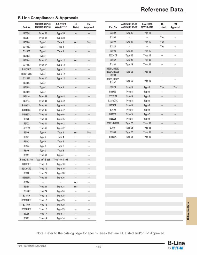
Reference Data
Reference Data
119Fire Protection Solutions
B-Line CompIiances & Approvals
B3096 Type 38 Type 39 -- --
B3097 Type 37 Type 38 -- --
B3100 Type 1 Type 1 Yes Yes
B3100C Type 1 Type 1 -- --
B3100F Type 1 Type 1 -- --
B3102 Type 1 -- -- --
B3104 Type 1* Type 12 Yes --
B3104C Type 1* Type 12 -- --
B3104CT Type 1 Type 12 -- --
B3104CTC Type 1 Type 12 -- --
B3104F Type 1* Type 12 -- --
B3106 Type 1 -- -- --
B3108 Type 1 Type 1 -- --
B3109 Type 1 -- -- --
B3110 Type 43 Type 44 -- --
B3114 Type 41 Type 42 -- --
B3117SL Type 44 Type 45 -- --
B3118SL Type 46 Type 47 -- --
B3119SL Type 45 Type 46 -- --
B3120 Type 44 Type 45 -- --
B3122 Type 41 Type 42 -- --
B3122A Type 41 Type 42 -- --
B3140 Type 4 Type 4 Yes Yes
B3141 Type 4 Type 4 -- --
B3142 Type 4 Type 4 -- --
B3144 Type 3 Type 3 -- --
B3146 Type 3 Type 3 -- --
B3151 Type 40 Type 41 -- --
B3160-B3165 Type 39A & 39B Type 40A & 40B -- --
B3170CT Type 10 Type 10 -- --
B3170CTC Type 10 Type 10 -- --
B3180 Type 26 Type 26 -- --
B3180FL Type 26 Type 26 -- --
B3184 -- -- Yes --
B3188 Type 24 Type 24 Yes --
B3188C Type 24 Type 24 -- --
B3198H Type 12 Type 25 -- --
B3198HCT Type 12 Type 25 -- --
B3198R Type 12 Type 25 -- --
B3198RCT Type 12 Type 25 -- --
B3200 Type 17 Type 17 -- --
B3201 Type 14 Type 14 -- --
ANSI/MSS SP-69 A-A-1192A UL FMPart No. ANSI/MSS SP-58 WW-H-171E Listed Approved
B3202 Type 13 Type 13 -- --
B3203 -- -- Yes --
B3222 Type 16 Type 16 Yes --
B3223 -- -- Yes --
B3224 Type 15 Type 15 -- --
B3224CT Type 15 Type 15 -- --
B3262 Type 48 Type 49 -- --
B3264 Type 49 Type 50 -- --
B3291, B3292B3294, B3296 Type 28 Type 28 -- --B3298
B3293, B3295Type 29 Type 29 --
--B3297
B3373 Type 8 Type 8 Yes Yes
B3373C Type 8 Type 8 -- --
B3373CT Type 8 Type 8 -- --
B3373CTC Type 8 Type 8 -- --
B3373F Type 8 Type 8 -- --
B3690 Type 5 Type 5 -- --
B3690C Type 5 Type 5 -- --
B3690F Type 5 Type 5 -- --
B3891-B3897 Type 35 Type 35 -- --
B3991 Type 35 Type 35 -- --
B3993 Type 35 Type 35 -- --
B3993A Type 35 Type 35 -- --
ANSI/MSS SP-69 A-A-1192A UL FMPart No. ANSI/MSS SP-58 WW-H-171E Listed Approved
Note: Refer to the catalog page for specific sizes that are UL Listed and/or FM Approved.
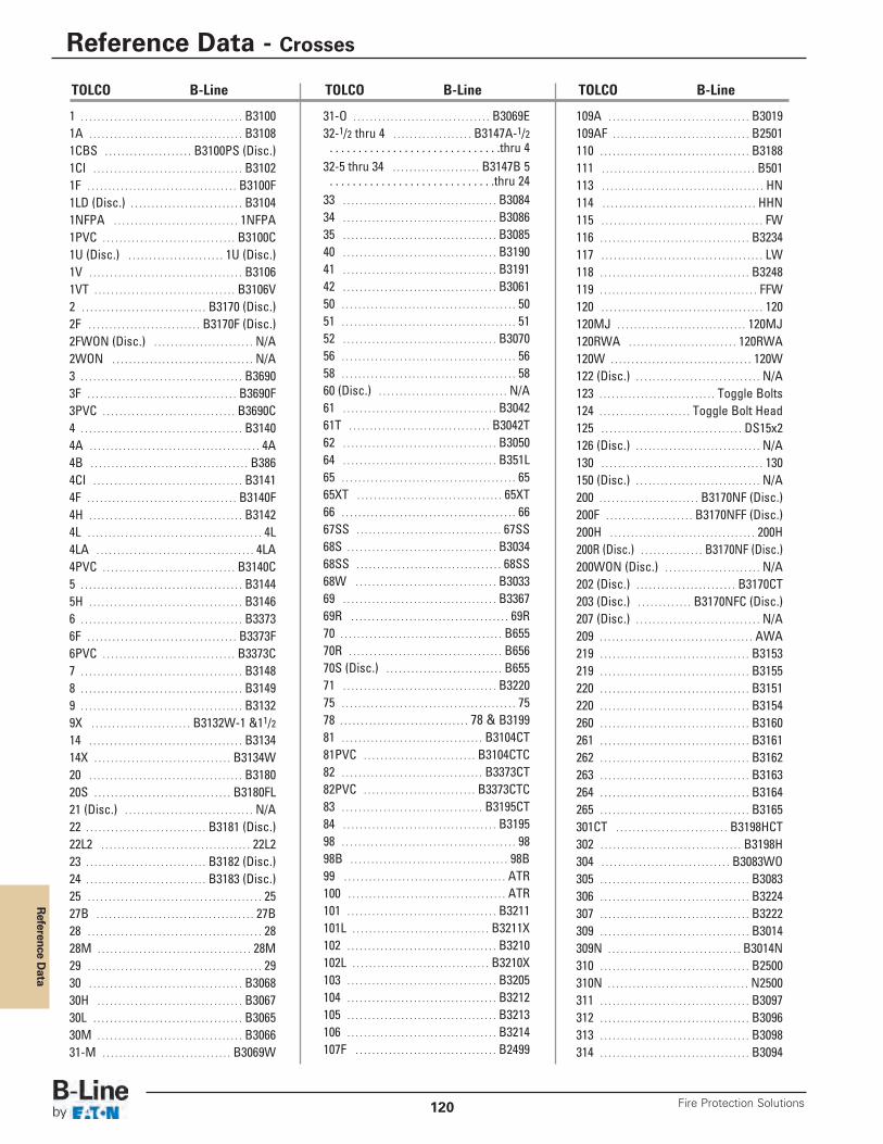
Reference D
ata
Reference Data - Crosses
Fire Protection Solutions120
1 . . . . . . . . . . . . . . . . . . . . . . . . . . . . . . . . . . . . . . . B31001A . . . . . . . . . . . . . . . . . . . . . . . . . . . . . . . . . . . . . B31081CBS . . . . . . . . . . . . . . . . . . . . . B3100PS (Disc.)1CI . . . . . . . . . . . . . . . . . . . . . . . . . . . . . . . . . . . . B31021F . . . . . . . . . . . . . . . . . . . . . . . . . . . . . . . . . . . . B3100F1LD (Disc.) . . . . . . . . . . . . . . . . . . . . . . . . . . . B31041NFPA . . . . . . . . . . . . . . . . . . . . . . . . . . . . . . 1NFPA1PVC . . . . . . . . . . . . . . . . . . . . . . . . . . . . . . . . B3100C1U (Disc.) . . . . . . . . . . . . . . . . . . . . . . . 1U (Disc.)1V . . . . . . . . . . . . . . . . . . . . . . . . . . . . . . . . . . . . . B31061VT . . . . . . . . . . . . . . . . . . . . . . . . . . . . . . . . . . B3106V2 . . . . . . . . . . . . . . . . . . . . . . . . . . . . . . B3170 (Disc.)2F . . . . . . . . . . . . . . . . . . . . . . . . . . . B3170F (Disc.)2FWON (Disc.) . . . . . . . . . . . . . . . . . . . . . . . . N/A2WON . . . . . . . . . . . . . . . . . . . . . . . . . . . . . . . . . . N/A3 . . . . . . . . . . . . . . . . . . . . . . . . . . . . . . . . . . . . . . . B36903F . . . . . . . . . . . . . . . . . . . . . . . . . . . . . . . . . . . . B3690F3PVC . . . . . . . . . . . . . . . . . . . . . . . . . . . . . . . . B3690C4 . . . . . . . . . . . . . . . . . . . . . . . . . . . . . . . . . . . . . . . B31404A . . . . . . . . . . . . . . . . . . . . . . . . . . . . . . . . . . . . . . . . . 4A4B . . . . . . . . . . . . . . . . . . . . . . . . . . . . . . . . . . . . . . B3864CI . . . . . . . . . . . . . . . . . . . . . . . . . . . . . . . . . . . . B31414F . . . . . . . . . . . . . . . . . . . . . . . . . . . . . . . . . . . . B3140F4H . . . . . . . . . . . . . . . . . . . . . . . . . . . . . . . . . . . . . B31424L . . . . . . . . . . . . . . . . . . . . . . . . . . . . . . . . . . . . . . . . . . 4L4LA . . . . . . . . . . . . . . . . . . . . . . . . . . . . . . . . . . . . . . 4LA4PVC . . . . . . . . . . . . . . . . . . . . . . . . . . . . . . . . B3140C5 . . . . . . . . . . . . . . . . . . . . . . . . . . . . . . . . . . . . . . . B31445H . . . . . . . . . . . . . . . . . . . . . . . . . . . . . . . . . . . . . B31466 . . . . . . . . . . . . . . . . . . . . . . . . . . . . . . . . . . . . . . . B33736F . . . . . . . . . . . . . . . . . . . . . . . . . . . . . . . . . . . . B3373F6PVC . . . . . . . . . . . . . . . . . . . . . . . . . . . . . . . . B3373C7 . . . . . . . . . . . . . . . . . . . . . . . . . . . . . . . . . . . . . . . B31488 . . . . . . . . . . . . . . . . . . . . . . . . . . . . . . . . . . . . . . . B31499 . . . . . . . . . . . . . . . . . . . . . . . . . . . . . . . . . . . . . . . B31329X . . . . . . . . . . . . . . . . . . . . . . . . B3132W-1 &11/214 . . . . . . . . . . . . . . . . . . . . . . . . . . . . . . . . . . . . . B313414X . . . . . . . . . . . . . . . . . . . . . . . . . . . . . . . . . B3134W20 . . . . . . . . . . . . . . . . . . . . . . . . . . . . . . . . . . . . . B318020S . . . . . . . . . . . . . . . . . . . . . . . . . . . . . . . . . B3180FL21 (Disc.) . . . . . . . . . . . . . . . . . . . . . . . . . . . . . . . N/A22 . . . . . . . . . . . . . . . . . . . . . . . . . . . . . B3181 (Disc.)22L2 . . . . . . . . . . . . . . . . . . . . . . . . . . . . . . . . . . . . 22L223 . . . . . . . . . . . . . . . . . . . . . . . . . . . . . B3182 (Disc.)24 . . . . . . . . . . . . . . . . . . . . . . . . . . . . . B3183 (Disc.)25 . . . . . . . . . . . . . . . . . . . . . . . . . . . . . . . . . . . . . . . . . . 2527B . . . . . . . . . . . . . . . . . . . . . . . . . . . . . . . . . . . . . . 27B28 . . . . . . . . . . . . . . . . . . . . . . . . . . . . . . . . . . . . . . . . . . 2828M . . . . . . . . . . . . . . . . . . . . . . . . . . . . . . . . . . . . . 28M29 . . . . . . . . . . . . . . . . . . . . . . . . . . . . . . . . . . . . . . . . . . 2930 . . . . . . . . . . . . . . . . . . . . . . . . . . . . . . . . . . . . . B306830H . . . . . . . . . . . . . . . . . . . . . . . . . . . . . . . . . . . B306730L . . . . . . . . . . . . . . . . . . . . . . . . . . . . . . . . . . . . B306530M . . . . . . . . . . . . . . . . . . . . . . . . . . . . . . . . . . . B306631-M . . . . . . . . . . . . . . . . . . . . . . . . . . . . . . . B3069W
109A . . . . . . . . . . . . . . . . . . . . . . . . . . . . . . . . . . B3019109AF . . . . . . . . . . . . . . . . . . . . . . . . . . . . . . . . . B2501110 . . . . . . . . . . . . . . . . . . . . . . . . . . . . . . . . . . . . B3188111 . . . . . . . . . . . . . . . . . . . . . . . . . . . . . . . . . . . . . B501113 . . . . . . . . . . . . . . . . . . . . . . . . . . . . . . . . . . . . . . . HN114 . . . . . . . . . . . . . . . . . . . . . . . . . . . . . . . . . . . . . HHN115 . . . . . . . . . . . . . . . . . . . . . . . . . . . . . . . . . . . . . . . FW116 . . . . . . . . . . . . . . . . . . . . . . . . . . . . . . . . . . . . B3234117 . . . . . . . . . . . . . . . . . . . . . . . . . . . . . . . . . . . . . . . LW118 . . . . . . . . . . . . . . . . . . . . . . . . . . . . . . . . . . . . B3248119 . . . . . . . . . . . . . . . . . . . . . . . . . . . . . . . . . . . . . . FFW120 . . . . . . . . . . . . . . . . . . . . . . . . . . . . . . . . . . . . . . . 120120MJ . . . . . . . . . . . . . . . . . . . . . . . . . . . . . . . 120MJ120RWA . . . . . . . . . . . . . . . . . . . . . . . . . . 120RWA120W . . . . . . . . . . . . . . . . . . . . . . . . . . . . . . . . . . 120W122 (Disc.) . . . . . . . . . . . . . . . . . . . . . . . . . . . . . . N/A123 . . . . . . . . . . . . . . . . . . . . . . . . . . . . Toggle Bolts124 . . . . . . . . . . . . . . . . . . . . . . Toggle Bolt Head125 . . . . . . . . . . . . . . . . . . . . . . . . . . . . . . . . . . DS15x2126 (Disc.) . . . . . . . . . . . . . . . . . . . . . . . . . . . . . . N/A130 . . . . . . . . . . . . . . . . . . . . . . . . . . . . . . . . . . . . . . . 130150 (Disc.) . . . . . . . . . . . . . . . . . . . . . . . . . . . . . . N/A200 . . . . . . . . . . . . . . . . . . . . . . . . B3170NF (Disc.)200F . . . . . . . . . . . . . . . . . . . . . B3170NFF (Disc.)200H . . . . . . . . . . . . . . . . . . . . . . . . . . . . . . . . . . . 200H200R (Disc.) . . . . . . . . . . . . . . . B3170NF (Disc.)200WON (Disc.) . . . . . . . . . . . . . . . . . . . . . . . N/A202 (Disc.) . . . . . . . . . . . . . . . . . . . . . . . . B3170CT203 (Disc.) . . . . . . . . . . . . . B3170NFC (Disc.)207 (Disc.) . . . . . . . . . . . . . . . . . . . . . . . . . . . . . . N/A209 . . . . . . . . . . . . . . . . . . . . . . . . . . . . . . . . . . . . . AWA219 . . . . . . . . . . . . . . . . . . . . . . . . . . . . . . . . . . . . B3153219 . . . . . . . . . . . . . . . . . . . . . . . . . . . . . . . . . . . . B3155220 . . . . . . . . . . . . . . . . . . . . . . . . . . . . . . . . . . . . B3151220 . . . . . . . . . . . . . . . . . . . . . . . . . . . . . . . . . . . . B3154260 . . . . . . . . . . . . . . . . . . . . . . . . . . . . . . . . . . . . B3160261 . . . . . . . . . . . . . . . . . . . . . . . . . . . . . . . . . . . . B3161262 . . . . . . . . . . . . . . . . . . . . . . . . . . . . . . . . . . . . B3162263 . . . . . . . . . . . . . . . . . . . . . . . . . . . . . . . . . . . . B3163264 . . . . . . . . . . . . . . . . . . . . . . . . . . . . . . . . . . . . B3164265 . . . . . . . . . . . . . . . . . . . . . . . . . . . . . . . . . . . . B3165301CT . . . . . . . . . . . . . . . . . . . . . . . . . . . B3198HCT302 . . . . . . . . . . . . . . . . . . . . . . . . . . . . . . . . . . B3198H304 . . . . . . . . . . . . . . . . . . . . . . . . . . . . . . . B3083WO305 . . . . . . . . . . . . . . . . . . . . . . . . . . . . . . . . . . . . B3083306 . . . . . . . . . . . . . . . . . . . . . . . . . . . . . . . . . . . . B3224307 . . . . . . . . . . . . . . . . . . . . . . . . . . . . . . . . . . . . B3222309 . . . . . . . . . . . . . . . . . . . . . . . . . . . . . . . . . . . . B3014309N . . . . . . . . . . . . . . . . . . . . . . . . . . . . . . . . B3014N310 . . . . . . . . . . . . . . . . . . . . . . . . . . . . . . . . . . . . B2500310N . . . . . . . . . . . . . . . . . . . . . . . . . . . . . . . . . . N2500311 . . . . . . . . . . . . . . . . . . . . . . . . . . . . . . . . . . . . B3097312 . . . . . . . . . . . . . . . . . . . . . . . . . . . . . . . . . . . . B3096313 . . . . . . . . . . . . . . . . . . . . . . . . . . . . . . . . . . . . B3098314 . . . . . . . . . . . . . . . . . . . . . . . . . . . . . . . . . . . . B3094
31-O . . . . . . . . . . . . . . . . . . . . . . . . . . . . . . . . . B3069E32-1/2 thru 4 . . . . . . . . . . . . . . . . . . . B3147A-1/2 . . . . . . . . . . . . . . . . . . . . . . . . . . . . . .thru 432-5 thru 34 . . . . . . . . . . . . . . . . . . . . . B3147B 5 . . . . . . . . . . . . . . . . . . . . . . . . . . . . .thru 2433 . . . . . . . . . . . . . . . . . . . . . . . . . . . . . . . . . . . . . B308434 . . . . . . . . . . . . . . . . . . . . . . . . . . . . . . . . . . . . . B308635 . . . . . . . . . . . . . . . . . . . . . . . . . . . . . . . . . . . . . B308540 . . . . . . . . . . . . . . . . . . . . . . . . . . . . . . . . . . . . . B319041 . . . . . . . . . . . . . . . . . . . . . . . . . . . . . . . . . . . . . B319142 . . . . . . . . . . . . . . . . . . . . . . . . . . . . . . . . . . . . . B306150 . . . . . . . . . . . . . . . . . . . . . . . . . . . . . . . . . . . . . . . . . . 5051 . . . . . . . . . . . . . . . . . . . . . . . . . . . . . . . . . . . . . . . . . . 5152 . . . . . . . . . . . . . . . . . . . . . . . . . . . . . . . . . . . . . B307056 . . . . . . . . . . . . . . . . . . . . . . . . . . . . . . . . . . . . . . . . . . 5658 . . . . . . . . . . . . . . . . . . . . . . . . . . . . . . . . . . . . . . . . . . 5860 (Disc.) . . . . . . . . . . . . . . . . . . . . . . . . . . . . . . . N/A61 . . . . . . . . . . . . . . . . . . . . . . . . . . . . . . . . . . . . . B304261T . . . . . . . . . . . . . . . . . . . . . . . . . . . . . . . . . . B3042T62 . . . . . . . . . . . . . . . . . . . . . . . . . . . . . . . . . . . . . B305064 . . . . . . . . . . . . . . . . . . . . . . . . . . . . . . . . . . . . . B351L65 . . . . . . . . . . . . . . . . . . . . . . . . . . . . . . . . . . . . . . . . . . 6565XT . . . . . . . . . . . . . . . . . . . . . . . . . . . . . . . . . . . 65XT66 . . . . . . . . . . . . . . . . . . . . . . . . . . . . . . . . . . . . . . . . . . 6667SS . . . . . . . . . . . . . . . . . . . . . . . . . . . . . . . . . . . 67SS68S . . . . . . . . . . . . . . . . . . . . . . . . . . . . . . . . . . . . B303468SS . . . . . . . . . . . . . . . . . . . . . . . . . . . . . . . . . . . 68SS68W . . . . . . . . . . . . . . . . . . . . . . . . . . . . . . . . . . B303369 . . . . . . . . . . . . . . . . . . . . . . . . . . . . . . . . . . . . . B336769R . . . . . . . . . . . . . . . . . . . . . . . . . . . . . . . . . . . . . . 69R70 . . . . . . . . . . . . . . . . . . . . . . . . . . . . . . . . . . . . . . . B65570R . . . . . . . . . . . . . . . . . . . . . . . . . . . . . . . . . . . . . B65670S (Disc.) . . . . . . . . . . . . . . . . . . . . . . . . . . . . B65571 . . . . . . . . . . . . . . . . . . . . . . . . . . . . . . . . . . . . . B322075 . . . . . . . . . . . . . . . . . . . . . . . . . . . . . . . . . . . . . . . . . . 7578 . . . . . . . . . . . . . . . . . . . . . . . . . . . . . . . 78 & B319981 . . . . . . . . . . . . . . . . . . . . . . . . . . . . . . . . . . B3104CT81PVC . . . . . . . . . . . . . . . . . . . . . . . . . . . B3104CTC82 . . . . . . . . . . . . . . . . . . . . . . . . . . . . . . . . . . B3373CT82PVC . . . . . . . . . . . . . . . . . . . . . . . . . . . B3373CTC83 . . . . . . . . . . . . . . . . . . . . . . . . . . . . . . . . . . B3195CT84 . . . . . . . . . . . . . . . . . . . . . . . . . . . . . . . . . . . . . B319598 . . . . . . . . . . . . . . . . . . . . . . . . . . . . . . . . . . . . . . . . . . 9898B . . . . . . . . . . . . . . . . . . . . . . . . . . . . . . . . . . . . . . 98B99 . . . . . . . . . . . . . . . . . . . . . . . . . . . . . . . . . . . . . . . ATR100 . . . . . . . . . . . . . . . . . . . . . . . . . . . . . . . . . . . . . . ATR101 . . . . . . . . . . . . . . . . . . . . . . . . . . . . . . . . . . . . B3211101L . . . . . . . . . . . . . . . . . . . . . . . . . . . . . . . . . B3211X102 . . . . . . . . . . . . . . . . . . . . . . . . . . . . . . . . . . . . B3210102L . . . . . . . . . . . . . . . . . . . . . . . . . . . . . . . . . B3210X103 . . . . . . . . . . . . . . . . . . . . . . . . . . . . . . . . . . . . B3205104 . . . . . . . . . . . . . . . . . . . . . . . . . . . . . . . . . . . . B3212105 . . . . . . . . . . . . . . . . . . . . . . . . . . . . . . . . . . . . B3213106 . . . . . . . . . . . . . . . . . . . . . . . . . . . . . . . . . . . . B3214107F . . . . . . . . . . . . . . . . . . . . . . . . . . . . . . . . . . B2499
TOLCO B-Line TOLCO B-Line TOLCO B-Line
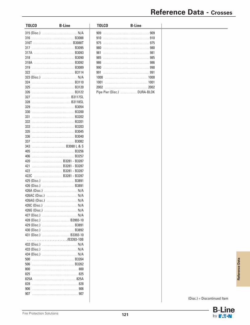
Reference Data
315 (Disc.) . . . . . . . . . . . . . . . . . . . . . . . . . . . . . . N/A316 . . . . . . . . . . . . . . . . . . . . . . . . . . . . . . . . . . . . B3088 316T . . . . . . . . . . . . . . . . . . . . . . . . . . . . . . . . . B3088T317 . . . . . . . . . . . . . . . . . . . . . . . . . . . . . . . . . . . . B3095317A . . . . . . . . . . . . . . . . . . . . . . . . . . . . . . . . . . B3093318 . . . . . . . . . . . . . . . . . . . . . . . . . . . . . . . . . . . . B3090318A . . . . . . . . . . . . . . . . . . . . . . . . . . . . . . . . . . B3092319 . . . . . . . . . . . . . . . . . . . . . . . . . . . . . . . . . . . . B3089322 . . . . . . . . . . . . . . . . . . . . . . . . . . . . . . . . . . . . B3114323 (Disc.) . . . . . . . . . . . . . . . . . . . . . . . . . . . . . . N/A324 . . . . . . . . . . . . . . . . . . . . . . . . . . . . . . . . . . . . B3110325 . . . . . . . . . . . . . . . . . . . . . . . . . . . . . . . . . . . . B3120326 . . . . . . . . . . . . . . . . . . . . . . . . . . . . . . . . . . . . B3122327 . . . . . . . . . . . . . . . . . . . . . . . . . . . . . . . . . B3117SL328 . . . . . . . . . . . . . . . . . . . . . . . . . . . . . . . . . B3118SL329 . . . . . . . . . . . . . . . . . . . . . . . . . . . . . . . . . . . . B3054330 . . . . . . . . . . . . . . . . . . . . . . . . . . . . . . . . . . . . B3200331 . . . . . . . . . . . . . . . . . . . . . . . . . . . . . . . . . . . . B3202332 . . . . . . . . . . . . . . . . . . . . . . . . . . . . . . . . . . . . B3201333 . . . . . . . . . . . . . . . . . . . . . . . . . . . . . . . . . . . . B3203335 . . . . . . . . . . . . . . . . . . . . . . . . . . . . . . . . . . . . B3045336 . . . . . . . . . . . . . . . . . . . . . . . . . . . . . . . . . . . . B3040337 . . . . . . . . . . . . . . . . . . . . . . . . . . . . . . . . . . . . B3082343 . . . . . . . . . . . . . . . . . . . . . . . . . . . . B3080 L & S405 . . . . . . . . . . . . . . . . . . . . . . . . . . . . . . . . . . . . B3256406 . . . . . . . . . . . . . . . . . . . . . . . . . . . . . . . . . . . . B3257420 . . . . . . . . . . . . . . . . . . . . . . . . . . B3281 - B3287421 . . . . . . . . . . . . . . . . . . . . . . . . . . B3281 - B3287422 . . . . . . . . . . . . . . . . . . . . . . . . . . B3281 - B3287422C . . . . . . . . . . . . . . . . . . . . . . . . B3281 - B3287425 (Disc.) . . . . . . . . . . . . . . . . . . . . . . . . . . . B3891426 (Disc.) . . . . . . . . . . . . . . . . . . . . . . . . . . . B3891426A (Disc.) . . . . . . . . . . . . . . . . . . . . . . . . . . . . N/A426AC (Disc.) . . . . . . . . . . . . . . . . . . . . . . . . . . N/A426AG (Disc.) . . . . . . . . . . . . . . . . . . . . . . . . . . N/A426C (Disc.) . . . . . . . . . . . . . . . . . . . . . . . . . . . . N/A426G (Disc.) . . . . . . . . . . . . . . . . . . . . . . . . . . . . N/A427 (Disc.) . . . . . . . . . . . . . . . . . . . . . . . . . . . . . . N/A428 (Disc.) . . . . . . . . . . . . . . . . . . . . . . . B3993-10429 (Disc.) . . . . . . . . . . . . . . . . . . . . . . . . . . . B3891430 (Disc.) . . . . . . . . . . . . . . . . . . . . . . . . . . . B3892431 (Disc.) . . . . . . . . . . . . . . . . . . . . . . . B3393-10 . . . . . . . . . . . . . . . . . . . . . . . . ./B3393-10B432 (Disc.) . . . . . . . . . . . . . . . . . . . . . . . . . . . . . . N/A433 (Disc.) . . . . . . . . . . . . . . . . . . . . . . . . . . . . . . N/A434 (Disc.) . . . . . . . . . . . . . . . . . . . . . . . . . . . . . . N/A500 . . . . . . . . . . . . . . . . . . . . . . . . . . . . . . . . . . . . B3264506 . . . . . . . . . . . . . . . . . . . . . . . . . . . . . . . . . . . . B3262800 . . . . . . . . . . . . . . . . . . . . . . . . . . . . . . . . . . . . . . . 800825 . . . . . . . . . . . . . . . . . . . . . . . . . . . . . . . . . . . . . . . 825825A . . . . . . . . . . . . . . . . . . . . . . . . . . . . . . . . . . . 825A828 . . . . . . . . . . . . . . . . . . . . . . . . . . . . . . . . . . . . . . . 828906 . . . . . . . . . . . . . . . . . . . . . . . . . . . . . . . . . . . . . . . 906907 . . . . . . . . . . . . . . . . . . . . . . . . . . . . . . . . . . . . . . . 907
TOLCO B-Line
909 . . . . . . . . . . . . . . . . . . . . . . . . . . . . . . . . . . . . . . . 909910 . . . . . . . . . . . . . . . . . . . . . . . . . . . . . . . . . . . . . . . 910975 . . . . . . . . . . . . . . . . . . . . . . . . . . . . . . . . . . . . . . . 975980 . . . . . . . . . . . . . . . . . . . . . . . . . . . . . . . . . . . . . . . 980981 . . . . . . . . . . . . . . . . . . . . . . . . . . . . . . . . . . . . . . . 981985 . . . . . . . . . . . . . . . . . . . . . . . . . . . . . . . . . . . . . . . 985986 . . . . . . . . . . . . . . . . . . . . . . . . . . . . . . . . . . . . . . . 986990 . . . . . . . . . . . . . . . . . . . . . . . . . . . . . . . . . . . . . . . 990991 . . . . . . . . . . . . . . . . . . . . . . . . . . . . . . . . . . . . . . . 9911000 . . . . . . . . . . . . . . . . . . . . . . . . . . . . . . . . . . . . 10001001 . . . . . . . . . . . . . . . . . . . . . . . . . . . . . . . . . . . . 10012002 . . . . . . . . . . . . . . . . . . . . . . . . . . . . . . . . . . . . 2002Pipe Pier (Disc.) . . . . . . . . . . . . . . DURA-BLOK
TOLCO B-Line
(Disc.) = Discontinued Item
Reference Data - Crosses
121Fire Protection Solutions
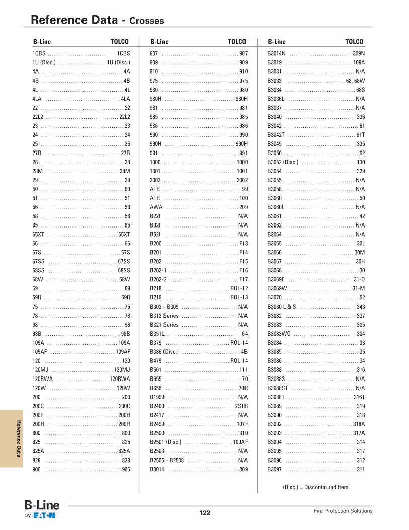
Reference D
ata
1CBS . . . . . . . . . . . . . . . . . . . . . . . . . . . . . . . . . 1CBS1U (Disc.) . . . . . . . . . . . . . . . . . . . . . . . 1U (Disc.)4A . . . . . . . . . . . . . . . . . . . . . . . . . . . . . . . . . . . . . . . 4A4B . . . . . . . . . . . . . . . . . . . . . . . . . . . . . . . . . . . . . . . 4B4L . . . . . . . . . . . . . . . . . . . . . . . . . . . . . . . . . . . . . . . . 4L4LA . . . . . . . . . . . . . . . . . . . . . . . . . . . . . . . . . . . . 4LA22 . . . . . . . . . . . . . . . . . . . . . . . . . . . . . . . . . . . . . . . . 2222L2 . . . . . . . . . . . . . . . . . . . . . . . . . . . . . . . . . . . 22L223 . . . . . . . . . . . . . . . . . . . . . . . . . . . . . . . . . . . . . . . . 2324 . . . . . . . . . . . . . . . . . . . . . . . . . . . . . . . . . . . . . . . . 2425 . . . . . . . . . . . . . . . . . . . . . . . . . . . . . . . . . . . . . . . . 2527B . . . . . . . . . . . . . . . . . . . . . . . . . . . . . . . . . . . . 27B28 . . . . . . . . . . . . . . . . . . . . . . . . . . . . . . . . . . . . . . . . 2828M . . . . . . . . . . . . . . . . . . . . . . . . . . . . . . . . . . . 28M29 . . . . . . . . . . . . . . . . . . . . . . . . . . . . . . . . . . . . . . . . 2950 . . . . . . . . . . . . . . . . . . . . . . . . . . . . . . . . . . . . . . . . 6051 . . . . . . . . . . . . . . . . . . . . . . . . . . . . . . . . . . . . . . . . 5156 . . . . . . . . . . . . . . . . . . . . . . . . . . . . . . . . . . . . . . . . 5658 . . . . . . . . . . . . . . . . . . . . . . . . . . . . . . . . . . . . . . . . 5865 . . . . . . . . . . . . . . . . . . . . . . . . . . . . . . . . . . . . . . . . 6565XT . . . . . . . . . . . . . . . . . . . . . . . . . . . . . . . . . . 65XT66 . . . . . . . . . . . . . . . . . . . . . . . . . . . . . . . . . . . . . . . . 6667S . . . . . . . . . . . . . . . . . . . . . . . . . . . . . . . . . . . . . 67S67SS . . . . . . . . . . . . . . . . . . . . . . . . . . . . . . . . . 67SS68SS . . . . . . . . . . . . . . . . . . . . . . . . . . . . . . . . . 68SS68W . . . . . . . . . . . . . . . . . . . . . . . . . . . . . . . . . . . 68W69 . . . . . . . . . . . . . . . . . . . . . . . . . . . . . . . . . . . . . . . . 6969R . . . . . . . . . . . . . . . . . . . . . . . . . . . . . . . . . . . . . 69R75 . . . . . . . . . . . . . . . . . . . . . . . . . . . . . . . . . . . . . . . . 7578 . . . . . . . . . . . . . . . . . . . . . . . . . . . . . . . . . . . . . . . . 7898 . . . . . . . . . . . . . . . . . . . . . . . . . . . . . . . . . . . . . . . . 9898B . . . . . . . . . . . . . . . . . . . . . . . . . . . . . . . . . . . . 98B109A . . . . . . . . . . . . . . . . . . . . . . . . . . . . . . . . . . 109A109AF . . . . . . . . . . . . . . . . . . . . . . . . . . . . . . . 109AF120 . . . . . . . . . . . . . . . . . . . . . . . . . . . . . . . . . . . . . 120120MJ . . . . . . . . . . . . . . . . . . . . . . . . . . . . . . 120MJ120RWA . . . . . . . . . . . . . . . . . . . . . . . . . 120RWA120W . . . . . . . . . . . . . . . . . . . . . . . . . . . . . . . . 120W200 . . . . . . . . . . . . . . . . . . . . . . . . . . . . . . . . . . . . . 200200C . . . . . . . . . . . . . . . . . . . . . . . . . . . . . . . . . . 200C200F . . . . . . . . . . . . . . . . . . . . . . . . . . . . . . . . . . 200H200H . . . . . . . . . . . . . . . . . . . . . . . . . . . . . . . . . . 200H800 . . . . . . . . . . . . . . . . . . . . . . . . . . . . . . . . . . . . . 800825 . . . . . . . . . . . . . . . . . . . . . . . . . . . . . . . . . . . . . 825825A . . . . . . . . . . . . . . . . . . . . . . . . . . . . . . . . . . 825A828 . . . . . . . . . . . . . . . . . . . . . . . . . . . . . . . . . . . . . 828906 . . . . . . . . . . . . . . . . . . . . . . . . . . . . . . . . . . . . . 906
B3014N . . . . . . . . . . . . . . . . . . . . . . . . . . . . . . 309NB3019 . . . . . . . . . . . . . . . . . . . . . . . . . . . . . . . . . 109AB3031 . . . . . . . . . . . . . . . . . . . . . . . . . . . . . . . . . . N/AB3033 . . . . . . . . . . . . . . . . . . . . . . . . . . . . . 68, 68WB3034 . . . . . . . . . . . . . . . . . . . . . . . . . . . . . . . . . . 68SB3036L . . . . . . . . . . . . . . . . . . . . . . . . . . . . . . . . N/AB3037 . . . . . . . . . . . . . . . . . . . . . . . . . . . . . . . . . . N/AB3040 . . . . . . . . . . . . . . . . . . . . . . . . . . . . . . . . . . 336B3042 . . . . . . . . . . . . . . . . . . . . . . . . . . . . . . . . . . . . 61B3042T . . . . . . . . . . . . . . . . . . . . . . . . . . . . . . . . . 61TB3045 . . . . . . . . . . . . . . . . . . . . . . . . . . . . . . . . . . 335B3050 . . . . . . . . . . . . . . . . . . . . . . . . . . . . . . . . . . . . 62B3052 (Disc.) . . . . . . . . . . . . . . . . . . . . . . . . . . 130B3054 . . . . . . . . . . . . . . . . . . . . . . . . . . . . . . . . . . 329B3055 . . . . . . . . . . . . . . . . . . . . . . . . . . . . . . . . . . N/AB3058 . . . . . . . . . . . . . . . . . . . . . . . . . . . . . . . . . . N/AB3060 . . . . . . . . . . . . . . . . . . . . . . . . . . . . . . . . . . . . 50B3060L . . . . . . . . . . . . . . . . . . . . . . . . . . . . . . . . N/AB3061 . . . . . . . . . . . . . . . . . . . . . . . . . . . . . . . . . . . . 42B3062 . . . . . . . . . . . . . . . . . . . . . . . . . . . . . . . . . . N/AB3064 . . . . . . . . . . . . . . . . . . . . . . . . . . . . . . . . . . N/AB3065 . . . . . . . . . . . . . . . . . . . . . . . . . . . . . . . . . . 30LB3066 . . . . . . . . . . . . . . . . . . . . . . . . . . . . . . . . . 30MB3067 . . . . . . . . . . . . . . . . . . . . . . . . . . . . . . . . . . 30HB3068 . . . . . . . . . . . . . . . . . . . . . . . . . . . . . . . . . . . . 30B3069E . . . . . . . . . . . . . . . . . . . . . . . . . . . . . . . 31-OB3069W . . . . . . . . . . . . . . . . . . . . . . . . . . . . . . 31-MB3070 . . . . . . . . . . . . . . . . . . . . . . . . . . . . . . . . . . . . 52B3080 L & S . . . . . . . . . . . . . . . . . . . . . . . . . . . 343B3082 . . . . . . . . . . . . . . . . . . . . . . . . . . . . . . . . . . 337B3083 . . . . . . . . . . . . . . . . . . . . . . . . . . . . . . . . . . 305B3083WO . . . . . . . . . . . . . . . . . . . . . . . . . . . . . . 304B3084 . . . . . . . . . . . . . . . . . . . . . . . . . . . . . . . . . . . . 33B3085 . . . . . . . . . . . . . . . . . . . . . . . . . . . . . . . . . . . . 35B3086 . . . . . . . . . . . . . . . . . . . . . . . . . . . . . . . . . . . . 34B3088 . . . . . . . . . . . . . . . . . . . . . . . . . . . . . . . . . . 316B3088S . . . . . . . . . . . . . . . . . . . . . . . . . . . . . . . . N/AB3088ST . . . . . . . . . . . . . . . . . . . . . . . . . . . . . . . N/AB3088T . . . . . . . . . . . . . . . . . . . . . . . . . . . . . . . 316TB3089 . . . . . . . . . . . . . . . . . . . . . . . . . . . . . . . . . . 319B3090 . . . . . . . . . . . . . . . . . . . . . . . . . . . . . . . . . . 318B3092 . . . . . . . . . . . . . . . . . . . . . . . . . . . . . . . . . 318AB3093 . . . . . . . . . . . . . . . . . . . . . . . . . . . . . . . . . 317AB3094 . . . . . . . . . . . . . . . . . . . . . . . . . . . . . . . . . . 314B3095 . . . . . . . . . . . . . . . . . . . . . . . . . . . . . . . . . . 317B3096 . . . . . . . . . . . . . . . . . . . . . . . . . . . . . . . . . . 312B3097 . . . . . . . . . . . . . . . . . . . . . . . . . . . . . . . . . . 311
907 . . . . . . . . . . . . . . . . . . . . . . . . . . . . . . . . . . . . . 907909 . . . . . . . . . . . . . . . . . . . . . . . . . . . . . . . . . . . . . 909910 . . . . . . . . . . . . . . . . . . . . . . . . . . . . . . . . . . . . . 910975 . . . . . . . . . . . . . . . . . . . . . . . . . . . . . . . . . . . . . 975980 . . . . . . . . . . . . . . . . . . . . . . . . . . . . . . . . . . . . . 980980H . . . . . . . . . . . . . . . . . . . . . . . . . . . . . . . . . . 980H981 . . . . . . . . . . . . . . . . . . . . . . . . . . . . . . . . . . . . . 981985 . . . . . . . . . . . . . . . . . . . . . . . . . . . . . . . . . . . . . 985986 . . . . . . . . . . . . . . . . . . . . . . . . . . . . . . . . . . . . . 986990 . . . . . . . . . . . . . . . . . . . . . . . . . . . . . . . . . . . . . 990990H . . . . . . . . . . . . . . . . . . . . . . . . . . . . . . . . . . 990H991 . . . . . . . . . . . . . . . . . . . . . . . . . . . . . . . . . . . . . 9911000 . . . . . . . . . . . . . . . . . . . . . . . . . . . . . . . . . . . 10001001 . . . . . . . . . . . . . . . . . . . . . . . . . . . . . . . . . . . 10012002 . . . . . . . . . . . . . . . . . . . . . . . . . . . . . . . . . . . 2002ATR . . . . . . . . . . . . . . . . . . . . . . . . . . . . . . . . . . . . . . 99ATR . . . . . . . . . . . . . . . . . . . . . . . . . . . . . . . . . . . . 100AWA . . . . . . . . . . . . . . . . . . . . . . . . . . . . . . . . . . . 209B22I . . . . . . . . . . . . . . . . . . . . . . . . . . . . . . . . . . . N/AB32I . . . . . . . . . . . . . . . . . . . . . . . . . . . . . . . . . . . N/AB52I . . . . . . . . . . . . . . . . . . . . . . . . . . . . . . . . . . . N/AB200 . . . . . . . . . . . . . . . . . . . . . . . . . . . . . . . . . . . . F13B201 . . . . . . . . . . . . . . . . . . . . . . . . . . . . . . . . . . . . F14B202 . . . . . . . . . . . . . . . . . . . . . . . . . . . . . . . . . . . . F15B202-1 . . . . . . . . . . . . . . . . . . . . . . . . . . . . . . . . . F16B202-2 . . . . . . . . . . . . . . . . . . . . . . . . . . . . . . . . . F17B218 . . . . . . . . . . . . . . . . . . . . . . . . . . . . . . . ROL-12B219 . . . . . . . . . . . . . . . . . . . . . . . . . . . . . . . ROL-13B303 - B309 . . . . . . . . . . . . . . . . . . . . . . . . . . . N/AB312 Series . . . . . . . . . . . . . . . . . . . . . . . . . . . N/AB321 Series . . . . . . . . . . . . . . . . . . . . . . . . . . . N/AB351L . . . . . . . . . . . . . . . . . . . . . . . . . . . . . . . . . . . . 64B379 . . . . . . . . . . . . . . . . . . . . . . . . . . . . . . . ROL-14B386 (Disc.) . . . . . . . . . . . . . . . . . . . . . . . . . . . . 4BB479 . . . . . . . . . . . . . . . . . . . . . . . . . . . . . . . ROL-14B501 . . . . . . . . . . . . . . . . . . . . . . . . . . . . . . . . . . . . 111B655 . . . . . . . . . . . . . . . . . . . . . . . . . . . . . . . . . . . . . 70B656 . . . . . . . . . . . . . . . . . . . . . . . . . . . . . . . . . . . 70RB1999 . . . . . . . . . . . . . . . . . . . . . . . . . . . . . . . . . . N/AB2400 . . . . . . . . . . . . . . . . . . . . . . . . . . . . . . . . 2STRB2417 . . . . . . . . . . . . . . . . . . . . . . . . . . . . . . . . . . N/AB2499 . . . . . . . . . . . . . . . . . . . . . . . . . . . . . . . . . 107FB2500 . . . . . . . . . . . . . . . . . . . . . . . . . . . . . . . . . . 310B2501 (Disc.) . . . . . . . . . . . . . . . . . . . . . . . 109AFB2503 . . . . . . . . . . . . . . . . . . . . . . . . . . . . . . . . . . N/AB2505 - B2508 . . . . . . . . . . . . . . . . . . . . . . . . N/AB3014 . . . . . . . . . . . . . . . . . . . . . . . . . . . . . . . . . . 309
B-Line TOLCO B-Line TOLCO B-Line TOLCO
(Disc.) = Discontinued Item
Reference Data - Crosses
Fire Protection Solutions122
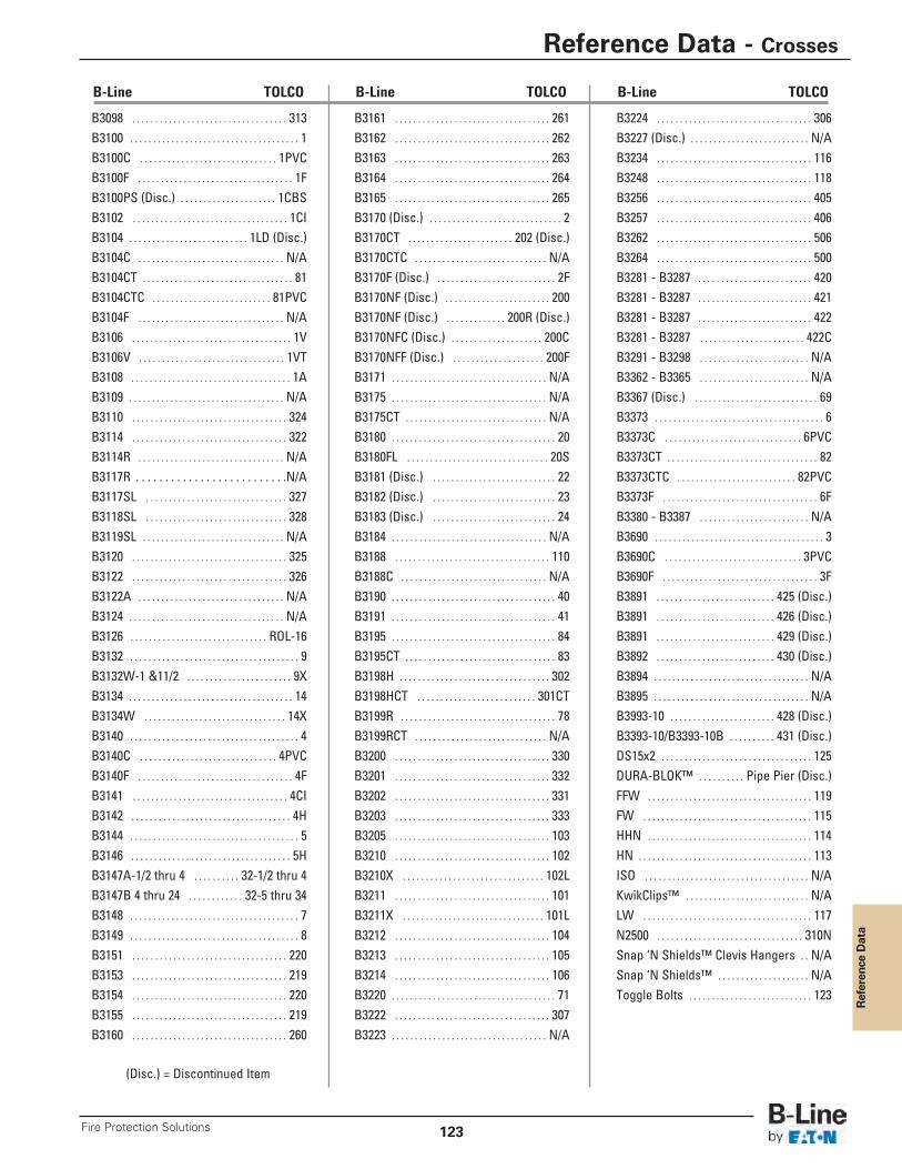
Reference Data
B3161 . . . . . . . . . . . . . . . . . . . . . . . . . . . . . . . . . . 261B3162 . . . . . . . . . . . . . . . . . . . . . . . . . . . . . . . . . . 262B3163 . . . . . . . . . . . . . . . . . . . . . . . . . . . . . . . . . . 263B3164 . . . . . . . . . . . . . . . . . . . . . . . . . . . . . . . . . . 264B3165 . . . . . . . . . . . . . . . . . . . . . . . . . . . . . . . . . . 265B3170 (Disc.) . . . . . . . . . . . . . . . . . . . . . . . . . . . . . 2B3170CT . . . . . . . . . . . . . . . . . . . . . . . 202 (Disc.)B3170CTC . . . . . . . . . . . . . . . . . . . . . . . . . . . . . N/AB3170F (Disc.) . . . . . . . . . . . . . . . . . . . . . . . . . . 2FB3170NF (Disc.) . . . . . . . . . . . . . . . . . . . . . . . 200B3170NF (Disc.) . . . . . . . . . . . . . 200R (Disc.)B3170NFC (Disc.) . . . . . . . . . . . . . . . . . . . . 200C B3170NFF (Disc.) . . . . . . . . . . . . . . . . . . . . 200FB3171 . . . . . . . . . . . . . . . . . . . . . . . . . . . . . . . . . . N/AB3175 . . . . . . . . . . . . . . . . . . . . . . . . . . . . . . . . . . N/AB3175CT . . . . . . . . . . . . . . . . . . . . . . . . . . . . . . . N/AB3180 . . . . . . . . . . . . . . . . . . . . . . . . . . . . . . . . . . . . 20B3180FL . . . . . . . . . . . . . . . . . . . . . . . . . . . . . . . 20SB3181 (Disc.) . . . . . . . . . . . . . . . . . . . . . . . . . . . 22B3182 (Disc.) . . . . . . . . . . . . . . . . . . . . . . . . . . . 23B3183 (Disc.) . . . . . . . . . . . . . . . . . . . . . . . . . . . 24B3184 . . . . . . . . . . . . . . . . . . . . . . . . . . . . . . . . . . N/AB3188 . . . . . . . . . . . . . . . . . . . . . . . . . . . . . . . . . . 110B3188C . . . . . . . . . . . . . . . . . . . . . . . . . . . . . . . . N/AB3190 . . . . . . . . . . . . . . . . . . . . . . . . . . . . . . . . . . . . 40B3191 . . . . . . . . . . . . . . . . . . . . . . . . . . . . . . . . . . . . 41B3195 . . . . . . . . . . . . . . . . . . . . . . . . . . . . . . . . . . . . 84B3195CT . . . . . . . . . . . . . . . . . . . . . . . . . . . . . . . . . 83B3198H . . . . . . . . . . . . . . . . . . . . . . . . . . . . . . . . . 302B3198HCT . . . . . . . . . . . . . . . . . . . . . . . . . . 301CTB3199R . . . . . . . . . . . . . . . . . . . . . . . . . . . . . . . . . . 78B3199RCT . . . . . . . . . . . . . . . . . . . . . . . . . . . . . N/AB3200 . . . . . . . . . . . . . . . . . . . . . . . . . . . . . . . . . . 330B3201 . . . . . . . . . . . . . . . . . . . . . . . . . . . . . . . . . . 332B3202 . . . . . . . . . . . . . . . . . . . . . . . . . . . . . . . . . . 331B3203 . . . . . . . . . . . . . . . . . . . . . . . . . . . . . . . . . . 333B3205 . . . . . . . . . . . . . . . . . . . . . . . . . . . . . . . . . . 103B3210 . . . . . . . . . . . . . . . . . . . . . . . . . . . . . . . . . . 102B3210X . . . . . . . . . . . . . . . . . . . . . . . . . . . . . . . 102LB3211 . . . . . . . . . . . . . . . . . . . . . . . . . . . . . . . . . . 101B3211X . . . . . . . . . . . . . . . . . . . . . . . . . . . . . . . 101LB3212 . . . . . . . . . . . . . . . . . . . . . . . . . . . . . . . . . . 104B3213 . . . . . . . . . . . . . . . . . . . . . . . . . . . . . . . . . . 105B3214 . . . . . . . . . . . . . . . . . . . . . . . . . . . . . . . . . . 106B3220 . . . . . . . . . . . . . . . . . . . . . . . . . . . . . . . . . . . . 71B3222 . . . . . . . . . . . . . . . . . . . . . . . . . . . . . . . . . . 307B3223 . . . . . . . . . . . . . . . . . . . . . . . . . . . . . . . . . . N/A
B3224 . . . . . . . . . . . . . . . . . . . . . . . . . . . . . . . . . . 306B3227 (Disc.) . . . . . . . . . . . . . . . . . . . . . . . . . . N/AB3234 . . . . . . . . . . . . . . . . . . . . . . . . . . . . . . . . . . 116B3248 . . . . . . . . . . . . . . . . . . . . . . . . . . . . . . . . . . 118B3256 . . . . . . . . . . . . . . . . . . . . . . . . . . . . . . . . . . 405B3257 . . . . . . . . . . . . . . . . . . . . . . . . . . . . . . . . . . 406B3262 . . . . . . . . . . . . . . . . . . . . . . . . . . . . . . . . . . 506B3264 . . . . . . . . . . . . . . . . . . . . . . . . . . . . . . . . . . 500B3281 - B3287 . . . . . . . . . . . . . . . . . . . . . . . . . 420B3281 - B3287 . . . . . . . . . . . . . . . . . . . . . . . . . 421B3281 - B3287 . . . . . . . . . . . . . . . . . . . . . . . . . 422B3281 - B3287 . . . . . . . . . . . . . . . . . . . . . . . 422CB3291 - B3298 . . . . . . . . . . . . . . . . . . . . . . . . N/AB3362 - B3365 . . . . . . . . . . . . . . . . . . . . . . . . N/AB3367 (Disc.) . . . . . . . . . . . . . . . . . . . . . . . . . . . 69B3373 . . . . . . . . . . . . . . . . . . . . . . . . . . . . . . . . . . . . . 6B3373C . . . . . . . . . . . . . . . . . . . . . . . . . . . . . . 6PVCB3373CT . . . . . . . . . . . . . . . . . . . . . . . . . . . . . . . . . 82B3373CTC . . . . . . . . . . . . . . . . . . . . . . . . . . 82PVCB3373F . . . . . . . . . . . . . . . . . . . . . . . . . . . . . . . . . . 6FB3380 - B3387 . . . . . . . . . . . . . . . . . . . . . . . . N/AB3690 . . . . . . . . . . . . . . . . . . . . . . . . . . . . . . . . . . . . . 3B3690C . . . . . . . . . . . . . . . . . . . . . . . . . . . . . . 3PVCB3690F . . . . . . . . . . . . . . . . . . . . . . . . . . . . . . . . . . 3FB3891 . . . . . . . . . . . . . . . . . . . . . . . . . . 425 (Disc.)B3891 . . . . . . . . . . . . . . . . . . . . . . . . . . 426 (Disc.)B3891 . . . . . . . . . . . . . . . . . . . . . . . . . . 429 (Disc.)B3892 . . . . . . . . . . . . . . . . . . . . . . . . . . 430 (Disc.)B3894 . . . . . . . . . . . . . . . . . . . . . . . . . . . . . . . . . . N/AB3895 . . . . . . . . . . . . . . . . . . . . . . . . . . . . . . . . . . N/AB3993-10 . . . . . . . . . . . . . . . . . . . . . . . 428 (Disc.)B3393-10/B3393-10B . . . . . . . . . . 431 (Disc.)DS15x2 . . . . . . . . . . . . . . . . . . . . . . . . . . . . . . . . . 125DURA-BLOK™ . . . . . . . . . . Pipe Pier (Disc.)FFW . . . . . . . . . . . . . . . . . . . . . . . . . . . . . . . . . . . . 119FW . . . . . . . . . . . . . . . . . . . . . . . . . . . . . . . . . . . . . 115HHN . . . . . . . . . . . . . . . . . . . . . . . . . . . . . . . . . . . . 114HN . . . . . . . . . . . . . . . . . . . . . . . . . . . . . . . . . . . . . . 113ISO . . . . . . . . . . . . . . . . . . . . . . . . . . . . . . . . . . . . N/AKwikClips™ . . . . . . . . . . . . . . . . . . . . . . . . . . . N/ALW . . . . . . . . . . . . . . . . . . . . . . . . . . . . . . . . . . . . . 117N2500 . . . . . . . . . . . . . . . . . . . . . . . . . . . . . . . . 310NSnap ‘N Shields™ Clevis Hangers . . N/ASnap ‘N Shields™ . . . . . . . . . . . . . . . . . . . . N/AToggle Bolts . . . . . . . . . . . . . . . . . . . . . . . . . . . 123
B-Line TOLCO B-Line TOLCO
B3098 . . . . . . . . . . . . . . . . . . . . . . . . . . . . . . . . . . 313B3100 . . . . . . . . . . . . . . . . . . . . . . . . . . . . . . . . . . . . . 1B3100C . . . . . . . . . . . . . . . . . . . . . . . . . . . . . . 1PVCB3100F . . . . . . . . . . . . . . . . . . . . . . . . . . . . . . . . . . 1FB3100PS (Disc.) . . . . . . . . . . . . . . . . . . . . . 1CBSB3102 . . . . . . . . . . . . . . . . . . . . . . . . . . . . . . . . . . 1CIB3104 . . . . . . . . . . . . . . . . . . . . . . . . . . 1LD (Disc.)B3104C . . . . . . . . . . . . . . . . . . . . . . . . . . . . . . . . N/AB3104CT . . . . . . . . . . . . . . . . . . . . . . . . . . . . . . . . . 81B3104CTC . . . . . . . . . . . . . . . . . . . . . . . . . . 81PVCB3104F . . . . . . . . . . . . . . . . . . . . . . . . . . . . . . . . N/AB3106 . . . . . . . . . . . . . . . . . . . . . . . . . . . . . . . . . . . 1VB3106V . . . . . . . . . . . . . . . . . . . . . . . . . . . . . . . . 1VTB3108 . . . . . . . . . . . . . . . . . . . . . . . . . . . . . . . . . . . 1AB3109 . . . . . . . . . . . . . . . . . . . . . . . . . . . . . . . . . . N/AB3110 . . . . . . . . . . . . . . . . . . . . . . . . . . . . . . . . . . 324B3114 . . . . . . . . . . . . . . . . . . . . . . . . . . . . . . . . . . 322B3114R . . . . . . . . . . . . . . . . . . . . . . . . . . . . . . . . N/AB3117R . . . . . . . . . . . . . . . . . . . . . . . . . .N/AB3117SL . . . . . . . . . . . . . . . . . . . . . . . . . . . . . . . 327B3118SL . . . . . . . . . . . . . . . . . . . . . . . . . . . . . . . 328B3119SL . . . . . . . . . . . . . . . . . . . . . . . . . . . . . . . N/AB3120 . . . . . . . . . . . . . . . . . . . . . . . . . . . . . . . . . . 325B3122 . . . . . . . . . . . . . . . . . . . . . . . . . . . . . . . . . . 326B3122A . . . . . . . . . . . . . . . . . . . . . . . . . . . . . . . . N/AB3124 . . . . . . . . . . . . . . . . . . . . . . . . . . . . . . . . . . N/AB3126 . . . . . . . . . . . . . . . . . . . . . . . . . . . . . . ROL-16B3132 . . . . . . . . . . . . . . . . . . . . . . . . . . . . . . . . . . . . . 9B3132W-1 &11/2 . . . . . . . . . . . . . . . . . . . . . . . 9XB3134 . . . . . . . . . . . . . . . . . . . . . . . . . . . . . . . . . . . . 14B3134W . . . . . . . . . . . . . . . . . . . . . . . . . . . . . . . 14XB3140 . . . . . . . . . . . . . . . . . . . . . . . . . . . . . . . . . . . . . 4B3140C . . . . . . . . . . . . . . . . . . . . . . . . . . . . . . 4PVCB3140F . . . . . . . . . . . . . . . . . . . . . . . . . . . . . . . . . . 4FB3141 . . . . . . . . . . . . . . . . . . . . . . . . . . . . . . . . . . 4CIB3142 . . . . . . . . . . . . . . . . . . . . . . . . . . . . . . . . . . . 4HB3144 . . . . . . . . . . . . . . . . . . . . . . . . . . . . . . . . . . . . . 5B3146 . . . . . . . . . . . . . . . . . . . . . . . . . . . . . . . . . . . 5HB3147A-1/2 thru 4 . . . . . . . . . . 32-1/2 thru 4B3147B 4 thru 24 . . . . . . . . . . . . 32-5 thru 34B3148 . . . . . . . . . . . . . . . . . . . . . . . . . . . . . . . . . . . . . 7B3149 . . . . . . . . . . . . . . . . . . . . . . . . . . . . . . . . . . . . . 8B3151 . . . . . . . . . . . . . . . . . . . . . . . . . . . . . . . . . . 220B3153 . . . . . . . . . . . . . . . . . . . . . . . . . . . . . . . . . . 219B3154 . . . . . . . . . . . . . . . . . . . . . . . . . . . . . . . . . . 220B3155 . . . . . . . . . . . . . . . . . . . . . . . . . . . . . . . . . . 219B3160 . . . . . . . . . . . . . . . . . . . . . . . . . . . . . . . . . . 260
B-Line TOLCO
(Disc.) = Discontinued Item
Reference Data - Crosses
123Fire Protection Solutions
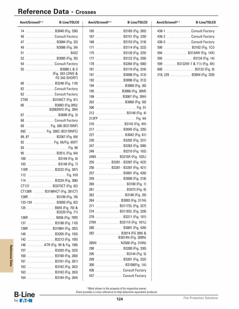
Reference D
ata
Reference Data - Crosses
Fire Protection Solutions124
14 . . . . . . . . . . . . . . . . . . . . . . . . . B3040 (Fig. 336)40 . . . . . . . . . . . . . . . . . . . . . . . . . Consult Factory47 . . . . . . . . . . . . . . . . . . . . . . . . . . . B3084 (Fig. 33)49 . . . . . . . . . . . . . . . . . . . . . . . . . . . B3086 (Fig. 34)51 . . . . . . . . . . . . . . . . . . . . . . . . . . . . . . . . . . . . . . . B42252 . . . . . . . . . . . . . . . . . . . . . . . . . . . B3085 (Fig. 35)54 . . . . . . . . . . . . . . . . . . . . . . . . . Consult Factory55 . . . . . . . . . . . . . . . . . . . . . . . . . . . . . . B3080 L & S
(Fig. 343 LONG &FG 343 SHORT)
60 . . . . . . . . . . . . . . . . . . . . . . . . . B3248 (Fig. 118)62 . . . . . . . . . . . . . . . . . . . . . . . . . Consult Factory63 . . . . . . . . . . . . . . . . . . . . . . . . . Consult FactoryCT65 . . . . . . . . . . . . . . . . . . . . B3104CT (Fig. 81)66 . . . . . . . . . . . . . . . . . . . . . . . . . B3083 (Fig.305)/
B3083WO (Fig. 304)67 . . . . . . . . . . . . . . . . . . . . . . . . . . . . B3690 (Fig. 3)68 . . . . . . . . . . . . . . . . . . . . . . . . . Consult Factory69 . . . . . . . . . . . . . . . . . . . . . . Fig. 200 (B3170NF)69C . . . . . . . . . . . . . . . . Fig. 200C (B3170NFC)89, 87 . . . . . . . . . . . . . . . . . . . . . . B3367 (Fig. 69)92 . . . . . . . . . . . . . . . . . . . . . . . . . Fig. 65/Fig. 65XT93 . . . . . . . . . . . . . . . . . . . . . . . . . . . . . . . . . . . . . Fig. 6695 . . . . . . . . . . . . . . . . . . . . . . . . . . . B351L (Fig. 64)100 . . . . . . . . . . . . . . . . . . . . . . . . . . . B3149 (Fig. 8)103 . . . . . . . . . . . . . . . . . . . . . . . . . . . B3148 (Fig. 7)110R . . . . . . . . . . . . . . . . . . . . . . B3222 (Fig. 307)112 . . . . . . . . . . . . . . . . . . . . . . . . . . . . . . . . . . Fig. 910114 . . . . . . . . . . . . . . . . . . . . . . . . B3224 (Fig. 306)CT121 . . . . . . . . . . . . . . . . . . B3373CT (Fig. 82)CT138R . . . . . . . . . . B3198HCT (Fig. 301CT)128R . . . . . . . . . . . . . . . . . . . . . . . . B3199 (Fig. 78)133-134 . . . . . . . . . . . . . . . . . . . . B3050 (Fig. 62)135 . . . . . . . . . . . . . . . . . . . . . . . . B655 (Fig. 70) &
B3220 (Fig. 71)136R . . . . . . . . . . . . . . . . . . . . . . . B656 (Fig. 70R)137 . . . . . . . . . . . . . . . . . . . . . . . . B3188 (Fig. 110)138R . . . . . . . . . . . . . . . . . . . . B3198H (Fig. 302)140 . . . . . . . . . . . . . . . . . . . . . . . . B3205 (Fig. 103)142 . . . . . . . . . . . . . . . . . . . . . . . . B3213 (Fig. 105)146 . . . . . . . . . . . . . . ATR (Fig. 99 & Fig. 100)157 . . . . . . . . . . . . . . . . . . . . . . . . B3203 (Fig. 333)160 . . . . . . . . . . . . . . . . . . . . . . . . B3160 (Fig. 260)161 . . . . . . . . . . . . . . . . . . . . . . . . B3161 (Fig. 261)162 . . . . . . . . . . . . . . . . . . . . . . . . B3162 (Fig. 262)163 . . . . . . . . . . . . . . . . . . . . . . . . B3163 (Fig. 263)164 . . . . . . . . . . . . . . . . . . . . . . . . B3164 (Fig. 264)
165 . . . . . . . . . . . . . . . . . . . . . . . . B3165 (Fig. 265)167 . . . . . . . . . . . . . . . . . . . . . . . . B3151 (Fig. 220)168 . . . . . . . . . . . . . . . . . . . . . . . . B3153 (Fig. 219)171 . . . . . . . . . . . . . . . . . . . . . . . . B3114 (Fig. 322)175 . . . . . . . . . . . . . . . . . . . . . . . . B3120 (Fig. 325)177 . . . . . . . . . . . . . . . . . . . . . . . . B3122 (Fig. 326)178 . . . . . . . . . . . . . . . . . . . . . . . . B3264 (Fig. 500)181 . . . . . . . . . . . . . . . . . . . . . . . . B3110 (Fig. 324)191 . . . . . . . . . . . . . . . . . . . . . . . . B3098 (Fig. 313)192 . . . . . . . . . . . . . . . . . . . . . . . . B3096 (Fig. 312)194 . . . . . . . . . . . . . . . . . . . . . . . . . B3068 (Fig. 30)195 . . . . . . . . . . . . . . . . . . . . . . . B3066 (Fig. 30M)199 . . . . . . . . . . . . . . . . . . . . . . . B3067 (Fig. 30H)202 . . . . . . . . . . . . . . . . . . . . . . . . . B3060 (Fig. 50)206 . . . . . . . . . . . . . . . . . . . . . . . . . . . . . . . . . . . . Fig. 51212 . . . . . . . . . . . . . . . . . . . . . . . . . . . B3140 (Fig. 4)212FP . . . . . . . . . . . . . . . . . . . . . . . . . . . . . . . . Fig. 4A216 . . . . . . . . . . . . . . . . . . . . . . . . . B3142 (Fig. 4H)217 . . . . . . . . . . . . . . . . . . . . . . . . B3045 (Fig. 335)227 . . . . . . . . . . . . . . . . . . . . . . . . . B3042 (Fig. 61)230 . . . . . . . . . . . . . . . . . . . . . . . . B3202 (Fig. 331)247 . . . . . . . . . . . . . . . . . . . . . . . . B3262 (Fig. 506)248 . . . . . . . . . . . . . . . . . . . . . . . . B3210 (Fig. 102)248X . . . . . . . . . . . . . . . . . . . B3210X (Fig. 102L)255 . . . . . . . . . . . . . B3281 - B3287 (Fig. 422)256 . . . . . . . . . . . . . B3281 - B3287 (Fig. 421)257 . . . . . . . . . . . . . . . . . . . . . . . . B3891 (Fig. 426)259 . . . . . . . . . . . . . . . . . . . . . . . . B3090 (Fig. 318)260 . . . . . . . . . . . . . . . . . . . . . . . . . . . B3100 (Fig. 1)261 . . . . . . . . . . . . . . . . . . . . . . . . . . . B3373 (Fig. 6)262 . . . . . . . . . . . . . . . . . . . . . . . . . B3180 (Fig. 20)264 . . . . . . . . . . . . . . . . . . . . . . B3093 (Fig. 317A)271 . . . . . . . . . . . . . . . . . . . . . B3117SL (Fig. 327)274 . . . . . . . . . . . . . . . . . . . . . B3118SL (Fig. 328)278 . . . . . . . . . . . . . . . . . . . . . . . . B3211 (Fig. 101)278X . . . . . . . . . . . . . . . . . . . B3211X (Fig. 101L)280 . . . . . . . . . . . . . . . . . . . . . . . . B3891 (Fig. 426)282 . . . . . . . . . . . . . . . . . . . . . . B3014 (FG 309) &
B3014N (Fig. 309N)285N . . . . . . . . . . . . . . . . . . . N2500 (Fig. 310N)290 . . . . . . . . . . . . . . . . . . . . . . . . B3200 (Fig. 330)295 . . . . . . . . . . . . . . . . . . . . . . . . . . . B3144 (Fig. 5)299 . . . . . . . . . . . . . . . . . . . . . . . . B3201 (Fig. 332)300 . . . . . . . . . . . . . . . . . . . . . . . . . . B3108(Fig. 1A)436 . . . . . . . . . . . . . . . . . . . . . . . . Consult Factory437 . . . . . . . . . . . . . . . . . . . . . . . . Consult Factory
438-1 . . . . . . . . . . . . . . . . . . . . . Consult Factory438-2 . . . . . . . . . . . . . . . . . . . . . Consult Factory438-3 . . . . . . . . . . . . . . . . . . . . . Consult Factory590 . . . . . . . . . . . . . . . . . . . . . . . . B3102 (Fig. 1CI)594 . . . . . . . . . . . . . . . . . . . . . B3134W (Fig. 14X)595 . . . . . . . . . . . . . . . . . . . . . . . . . B3134 (Fig. 14)599 . . . . . . . . . . . B3132W-1 & 11/2 (Fig. 9X)600 . . . . . . . . . . . . . . . . . . . . . . . . . . . B3132 (Fig. 9)218, 229 . . . . . . . . . . . . . . . . . . B3054 (Fig. 329)
Anvil/Grinnell® † B-Line/TOLCO Anvil/Grinnell® † B-Line/TOLCO Anvil/Grinnell® † B-Line/TOLCO
† Mark shown is the property of its respective owner.Chart provides a cross reference to help determine equivalent products.
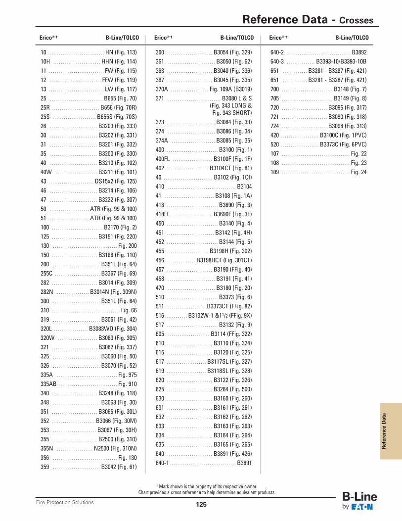
Reference Data
Reference Data - Crosses
125Fire Protection Solutions
10 . . . . . . . . . . . . . . . . . . . . . . . . . . . . . HN (Fig. 113)10H . . . . . . . . . . . . . . . . . . . . . . . . . HHN (Fig. 114)11 . . . . . . . . . . . . . . . . . . . . . . . . . . . . . FW (Fig. 115)12 . . . . . . . . . . . . . . . . . . . . . . . . . . . FFW (Fig. 119)13 . . . . . . . . . . . . . . . . . . . . . . . . . . . . . LW (Fig. 117)25 . . . . . . . . . . . . . . . . . . . . . . . . . . . . B655 (Fig. 70)25R . . . . . . . . . . . . . . . . . . . . . . . . . B656 (Fig. 70R)25S . . . . . . . . . . . . . . . . . . . . . . . B655S (Fig. 70S)26 . . . . . . . . . . . . . . . . . . . . . . . . . B3203 (Fig. 333)30 . . . . . . . . . . . . . . . . . . . . . . . . . B3202 (Fig. 331)31 . . . . . . . . . . . . . . . . . . . . . . . . . B3201 (Fig. 332)35 . . . . . . . . . . . . . . . . . . . . . . . . . B3200 (Fig. 330)40 . . . . . . . . . . . . . . . . . . . . . . . . . B3210 (Fig. 102)40W . . . . . . . . . . . . . . . . . . . . . . B3211 (Fig. 101)43 . . . . . . . . . . . . . . . . . . . . . . . . DS15x2 (Fig. 125)46 . . . . . . . . . . . . . . . . . . . . . . . . . B3214 (Fig. 106)47 . . . . . . . . . . . . . . . . . . . . . . . . . B3222 (Fig. 307)50 . . . . . . . . . . . . . . . . . . . . . ATR (Fig. 99 & 100)51 . . . . . . . . . . . . . . . . . . . . . ATR (Fig. 99 & 100)100 . . . . . . . . . . . . . . . . . . . . . . . . . . . B3170 (Fig. 2)125 . . . . . . . . . . . . . . . . . . . . . . . . B3151 (Fig. 220)130 . . . . . . . . . . . . . . . . . . . . . . . . . . . . . . . . . . Fig. 200150 . . . . . . . . . . . . . . . . . . . . . . . . B3188 (Fig. 110)200 . . . . . . . . . . . . . . . . . . . . . . . . . B351L (Fig. 64)255C . . . . . . . . . . . . . . . . . . . . . . . . B3367 (Fig. 69)282 . . . . . . . . . . . . . . . . . . . . . . . . B3014 (Fig. 309)282N . . . . . . . . . . . . . . . . . B3014N (Fig. 309N)300 . . . . . . . . . . . . . . . . . . . . . . . . . B351L (Fig. 64)310 . . . . . . . . . . . . . . . . . . . . . . . . . . . . . . . . . . . . Fig. 66319 . . . . . . . . . . . . . . . . . . . . . . . . . B3061 (Fig. 42)320L . . . . . . . . . . . . . . . . . . B3083WO (Fig. 304)320W . . . . . . . . . . . . . . . . . . . . . B3083 (Fig. 305)321 . . . . . . . . . . . . . . . . . . . . . . . . B3082 (Fig. 337)325 . . . . . . . . . . . . . . . . . . . . . . . . . B3060 (Fig. 50)326 . . . . . . . . . . . . . . . . . . . . . . . . . B3070 (Fig. 52)335A . . . . . . . . . . . . . . . . . . . . . . . . . . . . . . . . Fig. 975335AB . . . . . . . . . . . . . . . . . . . . . . . . . . . . . . Fig. 910340 . . . . . . . . . . . . . . . . . . . . . . . . B3248 (Fig. 118)348 . . . . . . . . . . . . . . . . . . . . . . . . . B3068 (Fig. 30)351 . . . . . . . . . . . . . . . . . . . . . . . . B3065 (Fig. 30L)352 . . . . . . . . . . . . . . . . . . . . . . . B3066 (Fig. 30M)353 . . . . . . . . . . . . . . . . . . . . . . . B3067 (Fig. 30H)355 . . . . . . . . . . . . . . . . . . . . . . . . B2500 (Fig. 310)355N . . . . . . . . . . . . . . . . . . . N2500 (Fig. 310N)356 . . . . . . . . . . . . . . . . . . . . . . . . . . . . . . . . . . Fig. 130359 . . . . . . . . . . . . . . . . . . . . . . . . . B3042 (Fig. 61)
360 . . . . . . . . . . . . . . . . . . . . . . . . B3054 (Fig. 329)361 . . . . . . . . . . . . . . . . . . . . . . . . . B3050 (Fig. 62)363 . . . . . . . . . . . . . . . . . . . . . . . . B3040 (Fig. 336)367 . . . . . . . . . . . . . . . . . . . . . . . . B3045 (Fig. 335)370A . . . . . . . . . . . . . . . . . . . . Fig. 109A (B3019)371 . . . . . . . . . . . . . . . . . . . . . . . . . . . . B3080 L & S
(Fig. 343 LONG &Fig. 343 SHORT)
373 . . . . . . . . . . . . . . . . . . . . . . . . . B3084 (Fig. 33)374 . . . . . . . . . . . . . . . . . . . . . . . . . B3086 (Fig. 34)374A . . . . . . . . . . . . . . . . . . . . . . . B3085 (Fig. 35)400 . . . . . . . . . . . . . . . . . . . . . . . . . . . B3100 (Fig. 1)400FL . . . . . . . . . . . . . . . . . . . . . B3100F (Fig. 1F)402 . . . . . . . . . . . . . . . . . . . . . . B3104CT (Fig. 81)40 . . . . . . . . . . . . . . . . . . . . . . . . . . B3102 (Fig. 1CI)410 . . . . . . . . . . . . . . . . . . . . . . . . . . . . . . . . . . . . B310441 . . . . . . . . . . . . . . . . . . . . . . . . . . B3108 (Fig. 1A)418 . . . . . . . . . . . . . . . . . . . . . . . . . . . B3690 (Fig. 3)418FL . . . . . . . . . . . . . . . . . . . . . B3690F (Fig. 3F)450 . . . . . . . . . . . . . . . . . . . . . . . . . . . B3140 (Fig. 4)451 . . . . . . . . . . . . . . . . . . . . . . . . . B3142 (Fig. 4H)452 . . . . . . . . . . . . . . . . . . . . . . . . . . . B3144 (Fig. 5)455 . . . . . . . . . . . . . . . . . . . . . . B3198H (Fig. 302)456 . . . . . . . . . . . . . . . B3198HCT (Fig. 301CT)457 . . . . . . . . . . . . . . . . . . . . . . . . B3190 (FFig. 40)458 . . . . . . . . . . . . . . . . . . . . . . . . . B3191 (Fig. 41)470 . . . . . . . . . . . . . . . . . . . . . . . . . B3180 (Fig. 20)510 . . . . . . . . . . . . . . . . . . . . . . . . . . . B3373 (Fig. 6)511 . . . . . . . . . . . . . . . . . . . . B3373CT (FFig. 82)516 . . . . . . . . . . . B3132W-1 &11/2 (FFig. 9X)517 . . . . . . . . . . . . . . . . . . . . . . . . . . . B3132 (Fig. 9)605 . . . . . . . . . . . . . . . . . . . . . . B3114 (FFig. 322)610 . . . . . . . . . . . . . . . . . . . . . . . . B3110 (Fig. 324)615 . . . . . . . . . . . . . . . . . . . . . . . . B3120 (Fig. 325)617 . . . . . . . . . . . . . . . . . . . . . B3117SL (Fig. 327)619 . . . . . . . . . . . . . . . . . . . . . B3118SL (Fig. 328)620 . . . . . . . . . . . . . . . . . . . . . . . . B3122 (Fig. 326)625 . . . . . . . . . . . . . . . . . . . . . . . . B3264 (Fig. 500)630 . . . . . . . . . . . . . . . . . . . . . . . . B3160 (Fig. 260)631 . . . . . . . . . . . . . . . . . . . . . . . . B3161 (Fig. 261)632 . . . . . . . . . . . . . . . . . . . . . . . . B3162 (Fig. 262)633 . . . . . . . . . . . . . . . . . . . . . . . . B3163 (Fig. 263)634 . . . . . . . . . . . . . . . . . . . . . . . . B3164 (Fig. 264)635 . . . . . . . . . . . . . . . . . . . . . . . . B3165 (Fig. 265)640 . . . . . . . . . . . . . . . . . . . . . . . . B3891 (Fig. 426)640-1 . . . . . . . . . . . . . . . . . . . . . . . . . . . . . . . . . . B3891
640-2 . . . . . . . . . . . . . . . . . . . . . . . . . . . . . . . . . . B3892640-3 . . . . . . . . . . . . . . . B3393-10/B3393-10B651 . . . . . . . . . . . . . B3281 - B3287 (Fig. 421)651 . . . . . . . . . . . . . B3281 - B3287 (Fig. 421)700 . . . . . . . . . . . . . . . . . . . . . . . . . . . B3148 (Fig. 7)705 . . . . . . . . . . . . . . . . . . . . . . . . . . . B3149 (Fig. 8)720 . . . . . . . . . . . . . . . . . . . . . . . . B3095 (Fig. 317)721 . . . . . . . . . . . . . . . . . . . . . . . . B3090 (Fig. 318)724 . . . . . . . . . . . . . . . . . . . . . . . . B3098 (Fig. 313)420 . . . . . . . . . . . . . . . . . . . . B3100C (Fig. 1PVC)520 . . . . . . . . . . . . . . . . . . . . B3373C (Fig. 6PVC)107 . . . . . . . . . . . . . . . . . . . . . . . . . . . . . . . . . . . . Fig. 22108 . . . . . . . . . . . . . . . . . . . . . . . . . . . . . . . . . . . . Fig. 23109 . . . . . . . . . . . . . . . . . . . . . . . . . . . . . . . . . . . . Fig. 24
Erico® † B-Line/TOLCO Erico® † B-Line/TOLCO Erico® † B-Line/TOLCO
† Mark shown is the property of its respective owner.Chart provides a cross reference to help determine equivalent products.
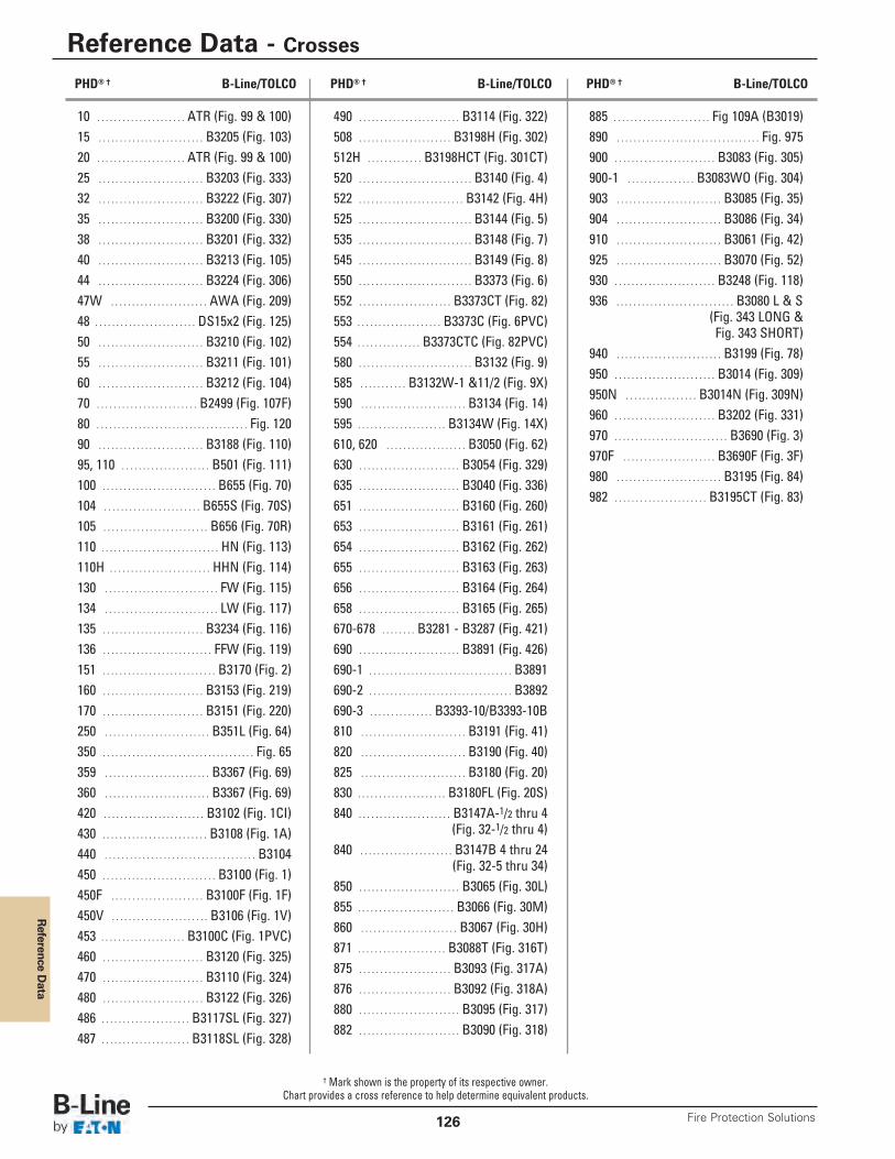
Reference D
ata
Reference Data - Crosses
Fire Protection Solutions126
10 . . . . . . . . . . . . . . . . . . . . . ATR (Fig. 99 & 100)15 . . . . . . . . . . . . . . . . . . . . . . . . . B3205 (Fig. 103)20 . . . . . . . . . . . . . . . . . . . . . ATR (Fig. 99 & 100)25 . . . . . . . . . . . . . . . . . . . . . . . . . B3203 (Fig. 333)32 . . . . . . . . . . . . . . . . . . . . . . . . . B3222 (Fig. 307)35 . . . . . . . . . . . . . . . . . . . . . . . . . B3200 (Fig. 330)38 . . . . . . . . . . . . . . . . . . . . . . . . . B3201 (Fig. 332)40 . . . . . . . . . . . . . . . . . . . . . . . . . B3213 (Fig. 105)44 . . . . . . . . . . . . . . . . . . . . . . . . . B3224 (Fig. 306)47W . . . . . . . . . . . . . . . . . . . . . . . AWA (Fig. 209)48 . . . . . . . . . . . . . . . . . . . . . . . . DS15x2 (Fig. 125)50 . . . . . . . . . . . . . . . . . . . . . . . . . B3210 (Fig. 102)55 . . . . . . . . . . . . . . . . . . . . . . . . . B3211 (Fig. 101)60 . . . . . . . . . . . . . . . . . . . . . . . . . B3212 (Fig. 104)70 . . . . . . . . . . . . . . . . . . . . . . . . B2499 (Fig. 107F)80 . . . . . . . . . . . . . . . . . . . . . . . . . . . . . . . . . . . . Fig. 12090 . . . . . . . . . . . . . . . . . . . . . . . . . B3188 (Fig. 110)95, 110 . . . . . . . . . . . . . . . . . . . . . B501 (Fig. 111)100 . . . . . . . . . . . . . . . . . . . . . . . . . . . B655 (Fig. 70)104 . . . . . . . . . . . . . . . . . . . . . . . B655S (Fig. 70S)105 . . . . . . . . . . . . . . . . . . . . . . . . . B656 (Fig. 70R)110 . . . . . . . . . . . . . . . . . . . . . . . . . . . . HN (Fig. 113)110H . . . . . . . . . . . . . . . . . . . . . . . . HHN (Fig. 114)130 . . . . . . . . . . . . . . . . . . . . . . . . . . . FW (Fig. 115)134 . . . . . . . . . . . . . . . . . . . . . . . . . . . LW (Fig. 117)135 . . . . . . . . . . . . . . . . . . . . . . . . B3234 (Fig. 116)136 . . . . . . . . . . . . . . . . . . . . . . . . . . FFW (Fig. 119)151 . . . . . . . . . . . . . . . . . . . . . . . . . . . B3170 (Fig. 2)160 . . . . . . . . . . . . . . . . . . . . . . . . B3153 (Fig. 219)170 . . . . . . . . . . . . . . . . . . . . . . . . B3151 (Fig. 220)250 . . . . . . . . . . . . . . . . . . . . . . . . . B351L (Fig. 64)350 . . . . . . . . . . . . . . . . . . . . . . . . . . . . . . . . . . . . Fig. 65359 . . . . . . . . . . . . . . . . . . . . . . . . . B3367 (Fig. 69)360 . . . . . . . . . . . . . . . . . . . . . . . . . B3367 (Fig. 69)420 . . . . . . . . . . . . . . . . . . . . . . . . B3102 (Fig. 1CI)430 . . . . . . . . . . . . . . . . . . . . . . . . . B3108 (Fig. 1A)440 . . . . . . . . . . . . . . . . . . . . . . . . . . . . . . . . . . . . B3104450 . . . . . . . . . . . . . . . . . . . . . . . . . . . B3100 (Fig. 1)450F . . . . . . . . . . . . . . . . . . . . . . B3100F (Fig. 1F)450V . . . . . . . . . . . . . . . . . . . . . . . B3106 (Fig. 1V)453 . . . . . . . . . . . . . . . . . . . . B3100C (Fig. 1PVC)460 . . . . . . . . . . . . . . . . . . . . . . . . B3120 (Fig. 325)470 . . . . . . . . . . . . . . . . . . . . . . . . B3110 (Fig. 324)480 . . . . . . . . . . . . . . . . . . . . . . . . B3122 (Fig. 326)486 . . . . . . . . . . . . . . . . . . . . . B3117SL (Fig. 327)487 . . . . . . . . . . . . . . . . . . . . . B3118SL (Fig. 328)
490 . . . . . . . . . . . . . . . . . . . . . . . . B3114 (Fig. 322)508 . . . . . . . . . . . . . . . . . . . . . . B3198H (Fig. 302)512H . . . . . . . . . . . . . B3198HCT (Fig. 301CT)520 . . . . . . . . . . . . . . . . . . . . . . . . . . . B3140 (Fig. 4)522 . . . . . . . . . . . . . . . . . . . . . . . . . B3142 (Fig. 4H)525 . . . . . . . . . . . . . . . . . . . . . . . . . . . B3144 (Fig. 5)535 . . . . . . . . . . . . . . . . . . . . . . . . . . . B3148 (Fig. 7)545 . . . . . . . . . . . . . . . . . . . . . . . . . . . B3149 (Fig. 8)550 . . . . . . . . . . . . . . . . . . . . . . . . . . . B3373 (Fig. 6)552 . . . . . . . . . . . . . . . . . . . . . . B3373CT (Fig. 82)553 . . . . . . . . . . . . . . . . . . . . B3373C (Fig. 6PVC)554 . . . . . . . . . . . . . . . B3373CTC (Fig. 82PVC)580 . . . . . . . . . . . . . . . . . . . . . . . . . . . B3132 (Fig. 9)585 . . . . . . . . . . . B3132W-1 &11/2 (Fig. 9X)590 . . . . . . . . . . . . . . . . . . . . . . . . . B3134 (Fig. 14)595 . . . . . . . . . . . . . . . . . . . . . B3134W (Fig. 14X)610, 620 . . . . . . . . . . . . . . . . . . . B3050 (Fig. 62)630 . . . . . . . . . . . . . . . . . . . . . . . . B3054 (Fig. 329)635 . . . . . . . . . . . . . . . . . . . . . . . . B3040 (Fig. 336)651 . . . . . . . . . . . . . . . . . . . . . . . . B3160 (Fig. 260)653 . . . . . . . . . . . . . . . . . . . . . . . . B3161 (Fig. 261)654 . . . . . . . . . . . . . . . . . . . . . . . . B3162 (Fig. 262)655 . . . . . . . . . . . . . . . . . . . . . . . . B3163 (Fig. 263)656 . . . . . . . . . . . . . . . . . . . . . . . . B3164 (Fig. 264)658 . . . . . . . . . . . . . . . . . . . . . . . . B3165 (Fig. 265)670-678 . . . . . . . . B3281 - B3287 (Fig. 421)690 . . . . . . . . . . . . . . . . . . . . . . . . B3891 (Fig. 426)690-1 . . . . . . . . . . . . . . . . . . . . . . . . . . . . . . . . . . B3891690-2 . . . . . . . . . . . . . . . . . . . . . . . . . . . . . . . . . . B3892690-3 . . . . . . . . . . . . . . . B3393-10/B3393-10B810 . . . . . . . . . . . . . . . . . . . . . . . . . B3191 (Fig. 41)820 . . . . . . . . . . . . . . . . . . . . . . . . . B3190 (Fig. 40)825 . . . . . . . . . . . . . . . . . . . . . . . . . B3180 (Fig. 20)830 . . . . . . . . . . . . . . . . . . . . . B3180FL (Fig. 20S)840 . . . . . . . . . . . . . . . . . . . . . . B3147A-1/2 thru 4
(Fig. 32-1/2 thru 4)840 . . . . . . . . . . . . . . . . . . . . . . B3147B 4 thru 24
(Fig. 32-5 thru 34)850 . . . . . . . . . . . . . . . . . . . . . . . . B3065 (Fig. 30L)855 . . . . . . . . . . . . . . . . . . . . . . . B3066 (Fig. 30M)860 . . . . . . . . . . . . . . . . . . . . . . . B3067 (Fig. 30H)871 . . . . . . . . . . . . . . . . . . . . . B3088T (Fig. 316T)875 . . . . . . . . . . . . . . . . . . . . . . B3093 (Fig. 317A)876 . . . . . . . . . . . . . . . . . . . . . . B3092 (Fig. 318A)880 . . . . . . . . . . . . . . . . . . . . . . . . B3095 (Fig. 317)882 . . . . . . . . . . . . . . . . . . . . . . . . B3090 (Fig. 318)
885 . . . . . . . . . . . . . . . . . . . . . . . Fig 109A (B3019)890 . . . . . . . . . . . . . . . . . . . . . . . . . . . . . . . . . . Fig. 975900 . . . . . . . . . . . . . . . . . . . . . . . . B3083 (Fig. 305)900-1 . . . . . . . . . . . . . . . . B3083WO (Fig. 304)903 . . . . . . . . . . . . . . . . . . . . . . . . . B3085 (Fig. 35)904 . . . . . . . . . . . . . . . . . . . . . . . . . B3086 (Fig. 34)910 . . . . . . . . . . . . . . . . . . . . . . . . . B3061 (Fig. 42)925 . . . . . . . . . . . . . . . . . . . . . . . . . B3070 (Fig. 52)930 . . . . . . . . . . . . . . . . . . . . . . . . B3248 (Fig. 118)936 . . . . . . . . . . . . . . . . . . . . . . . . . . . . B3080 L & S
(Fig. 343 LONG &Fig. 343 SHORT)
940 . . . . . . . . . . . . . . . . . . . . . . . . . B3199 (Fig. 78)950 . . . . . . . . . . . . . . . . . . . . . . . . B3014 (Fig. 309)950N . . . . . . . . . . . . . . . . . B3014N (Fig. 309N)960 . . . . . . . . . . . . . . . . . . . . . . . . B3202 (Fig. 331)970 . . . . . . . . . . . . . . . . . . . . . . . . . . . B3690 (Fig. 3)970F . . . . . . . . . . . . . . . . . . . . . . B3690F (Fig. 3F)980 . . . . . . . . . . . . . . . . . . . . . . . . . B3195 (Fig. 84)982 . . . . . . . . . . . . . . . . . . . . . . B3195CT (Fig. 83)
PHD® † B-Line/TOLCO PHD® † B-Line/TOLCO PHD® † B-Line/TOLCO
† Mark shown is the property of its respective owner.Chart provides a cross reference to help determine equivalent products.
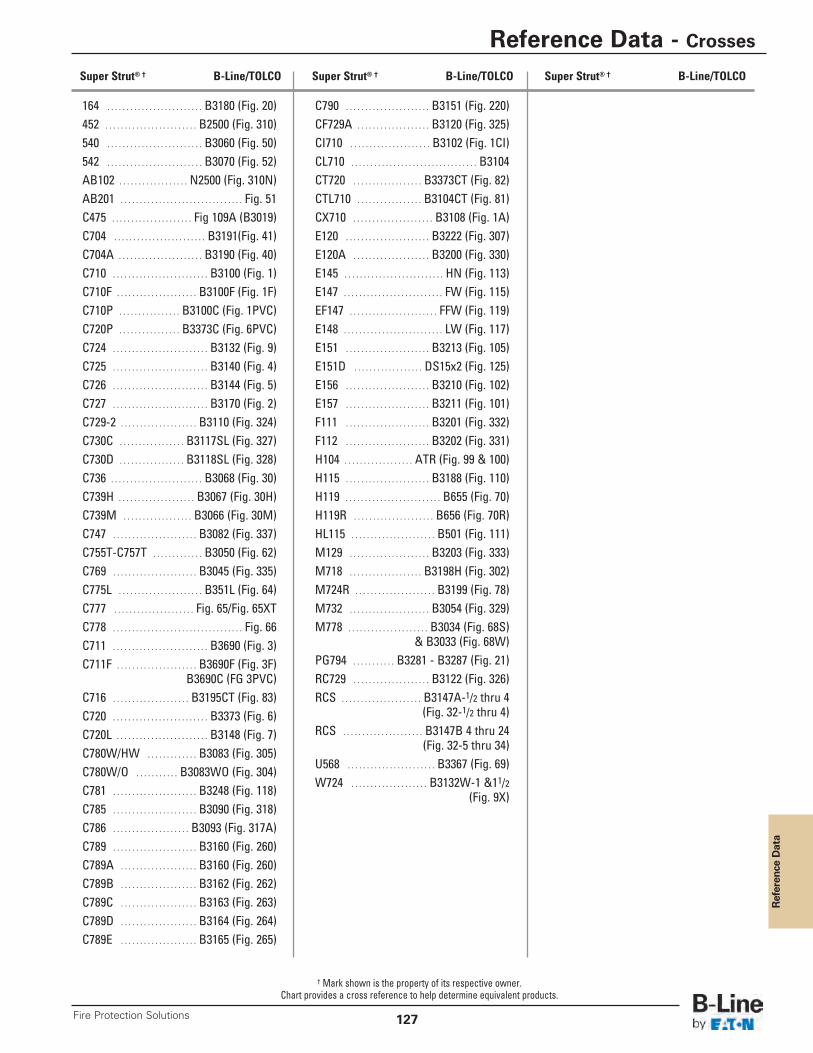
Reference Data
Reference Data - Crosses
127Fire Protection Solutions
164 . . . . . . . . . . . . . . . . . . . . . . . . . B3180 (Fig. 20)452 . . . . . . . . . . . . . . . . . . . . . . . . B2500 (Fig. 310)540 . . . . . . . . . . . . . . . . . . . . . . . . . B3060 (Fig. 50)542 . . . . . . . . . . . . . . . . . . . . . . . . . B3070 (Fig. 52)AB102 . . . . . . . . . . . . . . . . . . N2500 (Fig. 310N)AB201 . . . . . . . . . . . . . . . . . . . . . . . . . . . . . . . . Fig. 51C475 . . . . . . . . . . . . . . . . . . . . . Fig 109A (B3019)C704 . . . . . . . . . . . . . . . . . . . . . . . . B3191(Fig. 41)C704A . . . . . . . . . . . . . . . . . . . . . . B3190 (Fig. 40)C710 . . . . . . . . . . . . . . . . . . . . . . . . . B3100 (Fig. 1)C710F . . . . . . . . . . . . . . . . . . . . . B3100F (Fig. 1F)C710P . . . . . . . . . . . . . . . . B3100C (Fig. 1PVC)C720P . . . . . . . . . . . . . . . . B3373C (Fig. 6PVC)C724 . . . . . . . . . . . . . . . . . . . . . . . . . B3132 (Fig. 9)C725 . . . . . . . . . . . . . . . . . . . . . . . . . B3140 (Fig. 4)C726 . . . . . . . . . . . . . . . . . . . . . . . . . B3144 (Fig. 5)C727 . . . . . . . . . . . . . . . . . . . . . . . . . B3170 (Fig. 2)C729-2 . . . . . . . . . . . . . . . . . . . . B3110 (Fig. 324)C730C . . . . . . . . . . . . . . . . . B3117SL (Fig. 327)C730D . . . . . . . . . . . . . . . . . B3118SL (Fig. 328)C736 . . . . . . . . . . . . . . . . . . . . . . . . B3068 (Fig. 30)C739H . . . . . . . . . . . . . . . . . . . . B3067 (Fig. 30H)C739M . . . . . . . . . . . . . . . . . . B3066 (Fig. 30M)C747 . . . . . . . . . . . . . . . . . . . . . . B3082 (Fig. 337)C755T-C757T . . . . . . . . . . . . . B3050 (Fig. 62)C769 . . . . . . . . . . . . . . . . . . . . . . B3045 (Fig. 335)C775L . . . . . . . . . . . . . . . . . . . . . . B351L (Fig. 64)C777 . . . . . . . . . . . . . . . . . . . . . Fig. 65/Fig. 65XTC778 . . . . . . . . . . . . . . . . . . . . . . . . . . . . . . . . . . Fig. 66C711 . . . . . . . . . . . . . . . . . . . . . . . . . B3690 (Fig. 3)C711F . . . . . . . . . . . . . . . . . . . . . B3690F (Fig. 3F)
B3690C (FG 3PVC)C716 . . . . . . . . . . . . . . . . . . . . B3195CT (Fig. 83)C720 . . . . . . . . . . . . . . . . . . . . . . . . . B3373 (Fig. 6)C720L . . . . . . . . . . . . . . . . . . . . . . . . B3148 (Fig. 7)C780W/HW . . . . . . . . . . . . . B3083 (Fig. 305)C780W/O . . . . . . . . . . . B3083WO (Fig. 304)C781 . . . . . . . . . . . . . . . . . . . . . . B3248 (Fig. 118)C785 . . . . . . . . . . . . . . . . . . . . . . B3090 (Fig. 318)C786 . . . . . . . . . . . . . . . . . . . . B3093 (Fig. 317A)C789 . . . . . . . . . . . . . . . . . . . . . . B3160 (Fig. 260)C789A . . . . . . . . . . . . . . . . . . . . B3160 (Fig. 260)C789B . . . . . . . . . . . . . . . . . . . . B3162 (Fig. 262)C789C . . . . . . . . . . . . . . . . . . . . B3163 (Fig. 263)C789D . . . . . . . . . . . . . . . . . . . . B3164 (Fig. 264)C789E . . . . . . . . . . . . . . . . . . . . B3165 (Fig. 265)
C790 . . . . . . . . . . . . . . . . . . . . . . B3151 (Fig. 220)CF729A . . . . . . . . . . . . . . . . . . . B3120 (Fig. 325)CI710 . . . . . . . . . . . . . . . . . . . . . B3102 (Fig. 1CI)CL710 . . . . . . . . . . . . . . . . . . . . . . . . . . . . . . . . . B3104CT720 . . . . . . . . . . . . . . . . . . B3373CT (Fig. 82)CTL710 . . . . . . . . . . . . . . . . . B3104CT (Fig. 81)CX710 . . . . . . . . . . . . . . . . . . . . . B3108 (Fig. 1A)E120 . . . . . . . . . . . . . . . . . . . . . . B3222 (Fig. 307)E120A . . . . . . . . . . . . . . . . . . . . B3200 (Fig. 330)E145 . . . . . . . . . . . . . . . . . . . . . . . . . . HN (Fig. 113)E147 . . . . . . . . . . . . . . . . . . . . . . . . . . FW (Fig. 115)EF147 . . . . . . . . . . . . . . . . . . . . . . . FFW (Fig. 119)E148 . . . . . . . . . . . . . . . . . . . . . . . . . . LW (Fig. 117)E151 . . . . . . . . . . . . . . . . . . . . . . B3213 (Fig. 105)E151D . . . . . . . . . . . . . . . . . . DS15x2 (Fig. 125)E156 . . . . . . . . . . . . . . . . . . . . . . B3210 (Fig. 102)E157 . . . . . . . . . . . . . . . . . . . . . . B3211 (Fig. 101)F111 . . . . . . . . . . . . . . . . . . . . . . B3201 (Fig. 332)F112 . . . . . . . . . . . . . . . . . . . . . . B3202 (Fig. 331)H104 . . . . . . . . . . . . . . . . . . ATR (Fig. 99 & 100)H115 . . . . . . . . . . . . . . . . . . . . . . B3188 (Fig. 110)H119 . . . . . . . . . . . . . . . . . . . . . . . . . B655 (Fig. 70)H119R . . . . . . . . . . . . . . . . . . . . . B656 (Fig. 70R)HL115 . . . . . . . . . . . . . . . . . . . . . . B501 (Fig. 111)M129 . . . . . . . . . . . . . . . . . . . . . B3203 (Fig. 333)M718 . . . . . . . . . . . . . . . . . . . B3198H (Fig. 302)M724R . . . . . . . . . . . . . . . . . . . . . B3199 (Fig. 78)M732 . . . . . . . . . . . . . . . . . . . . . B3054 (Fig. 329)M778 . . . . . . . . . . . . . . . . . . . . . B3034 (Fig. 68S)
& B3033 (Fig. 68W)PG794 . . . . . . . . . . . B3281 - B3287 (Fig. 21)RC729 . . . . . . . . . . . . . . . . . . . . B3122 (Fig. 326)RCS . . . . . . . . . . . . . . . . . . . . . B3147A-1/2 thru 4
(Fig. 32-1/2 thru 4)RCS . . . . . . . . . . . . . . . . . . . . . B3147B 4 thru 24
(Fig. 32-5 thru 34)U568 . . . . . . . . . . . . . . . . . . . . . . . B3367 (Fig. 69)W724 . . . . . . . . . . . . . . . . . . . . B3132W-1 &11/2
(Fig. 9X)
Super Strut® † B-Line/TOLCO Super Strut® † B-Line/TOLCO Super Strut® † B-Line/TOLCO
† Mark shown is the property of its respective owner.Chart provides a cross reference to help determine equivalent products.
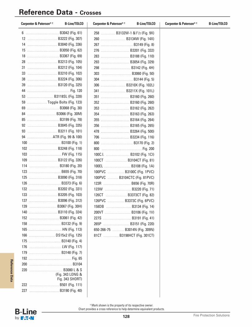
Reference D
ata
Reference Data - Crosses
Fire Protection Solutions128
6 . . . . . . . . . . . . . . . . . . . . . . . . . . . . B3042 (Fig. 61)12 . . . . . . . . . . . . . . . . . . . . . . . . . B3222 (Fig. 307)14 . . . . . . . . . . . . . . . . . . . . . . . . . B3040 (Fig. 336)15 . . . . . . . . . . . . . . . . . . . . . . . . . . . B3050 (Fig. 62)18 . . . . . . . . . . . . . . . . . . . . . . . . . . . B3367 (Fig. 69)28 . . . . . . . . . . . . . . . . . . . . . . . . . B3213 (Fig. 105)31 . . . . . . . . . . . . . . . . . . . . . . . . . B3212 (Fig. 104)33 . . . . . . . . . . . . . . . . . . . . . . . . . B3210 (Fig. 102)38 . . . . . . . . . . . . . . . . . . . . . . . . . B3224 (Fig. 306)39 . . . . . . . . . . . . . . . . . . . . . . . . . B3120 (Fig. 325)44 . . . . . . . . . . . . . . . . . . . . . . . . . . . . . . . . . . . . Fig. 12053 . . . . . . . . . . . . . . . . . . . . . . B3118SL (Fig. 328)59 . . . . . . . . . . . . . . . . . Toggle Bolts (Fig. 123)69 . . . . . . . . . . . . . . . . . . . . . . . . . . . B3068 (Fig. 30)84 . . . . . . . . . . . . . . . . . . . . . . . . B3066 (Fig. 30M)85 . . . . . . . . . . . . . . . . . . . . . . . . . . . B3199 (Fig. 78)92 . . . . . . . . . . . . . . . . . . . . . . . . . B3045 (Fig. 335)93 . . . . . . . . . . . . . . . . . . . . . . . . . B3211 (Fig. 101)94 . . . . . . . . . . . . . . . . . . . . . ATR (Fig. 99 & 100)100 . . . . . . . . . . . . . . . . . . . . . . . . . . . B3100 (Fig. 1)102 . . . . . . . . . . . . . . . . . . . . . . . . B3248 (Fig. 118)103 . . . . . . . . . . . . . . . . . . . . . . . . . . . FW (Fig. 115)109 . . . . . . . . . . . . . . . . . . . . . . . . B3122 (Fig. 326)114 . . . . . . . . . . . . . . . . . . . . . . . . . B3180 (Fig. 20)123 . . . . . . . . . . . . . . . . . . . . . . . . . . . B655 (Fig. 70)125 . . . . . . . . . . . . . . . . . . . . . . . . B3090 (Fig. 318)126 . . . . . . . . . . . . . . . . . . . . . . . . . . . B3373 (Fig. 6)132 . . . . . . . . . . . . . . . . . . . . . . . . B3202 (Fig. 331)133 . . . . . . . . . . . . . . . . . . . . . . . . B3205 (Fig. 103)137 . . . . . . . . . . . . . . . . . . . . . . . . B3096 (Fig. 312)139 . . . . . . . . . . . . . . . . . . . . . . . B3067 (Fig. 30H)140 . . . . . . . . . . . . . . . . . . . . . . . . B3110 (Fig. 324)152 . . . . . . . . . . . . . . . . . . . . . . . . . B3061 (Fig. 42)158 . . . . . . . . . . . . . . . . . . . . . . . . . . . B3132 (Fig. 9)165 . . . . . . . . . . . . . . . . . . . . . . . . . . . . HN (Fig. 113)166 . . . . . . . . . . . . . . . . . . . . . . DS15x2 (Fig. 125)175 . . . . . . . . . . . . . . . . . . . . . . . . . . . B3140 (Fig. 4)176 . . . . . . . . . . . . . . . . . . . . . . . . . . . LW (Fig. 117)179 . . . . . . . . . . . . . . . . . . . . . . . . . . . B3148 (Fig. 7)192 . . . . . . . . . . . . . . . . . . . . . . . . . . . . . . . . . . . . Fig. 65200 . . . . . . . . . . . . . . . . . . . . . . . . . . . . . . . . . . . . B3104220 . . . . . . . . . . . . . . . . . . . . . . . . . . . . B3080 L & S
(Fig. 343 LONG &Fig. 343 SHORT)
222 . . . . . . . . . . . . . . . . . . . . . . . . . B501 (Fig. 111)227 . . . . . . . . . . . . . . . . . . . . . . . . . B3190 (Fig. 40)
258 . . . . . . . . . . . . B3132W-1 &11/2 (Fig. 9X)260 . . . . . . . . . . . . . . . . . . . . . B3134W (Fig. 14X)267 . . . . . . . . . . . . . . . . . . . . . . . . . . . B3149 (Fig. 8)276 . . . . . . . . . . . . . . . . . . . . . . . . B3201 (Fig. 332)283 . . . . . . . . . . . . . . . . . . . . . . . . B3188 (Fig. 110)293 . . . . . . . . . . . . . . . . . . . . . . . . B3054 (Fig. 329)298 . . . . . . . . . . . . . . . . . . . . . . . . . B3142 (Fig. 4H)303 . . . . . . . . . . . . . . . . . . . . . . . . . B3060 (Fig. 50)304 . . . . . . . . . . . . . . . . . . . . . . . . . . . B3144 (Fig. 5)306 . . . . . . . . . . . . . . . . . . . . . B3210X (Fig. 102L)341 . . . . . . . . . . . . . . . . . . . . . B3211X (Fig. 101L)351 . . . . . . . . . . . . . . . . . . . . . . . . B3160 (Fig. 260)352 . . . . . . . . . . . . . . . . . . . . . . . . B3160 (Fig. 260)353 . . . . . . . . . . . . . . . . . . . . . . . . B3162 (Fig. 262)354 . . . . . . . . . . . . . . . . . . . . . . . . B3163 (Fig. 263)355 . . . . . . . . . . . . . . . . . . . . . . . . B3164 (Fig. 264)356 . . . . . . . . . . . . . . . . . . . . . . . . B3165 (Fig. 265)478 . . . . . . . . . . . . . . . . . . . . . . . . B3264 (Fig. 500)706 . . . . . . . . . . . . . . . . . . . . . . . . B3234 (Fig. 116)800 . . . . . . . . . . . . . . . . . . . . . . . . . . . B3170 (Fig. 2)800 . . . . . . . . . . . . . . . . . . . . . . . . . . . . . . . . . . Fig. 200100C.I. . . . . . . . . . . . . . . . . . . . . B3102 (Fig. 1CI)100CT . . . . . . . . . . . . . . . . . . B3104CT (Fig. 81)100EL . . . . . . . . . . . . . . . . . . . . . . B3108 (Fig. 1A)100PVC . . . . . . . . . . . . . . B3100C (Fig. 1PVC)100PVC . . . . . . . . . B3104CTC (Fig. 81PVC)123R . . . . . . . . . . . . . . . . . . . . . . . B656 (Fig. 70R)123W . . . . . . . . . . . . . . . . . . . . . . B3220 (Fig. 71)126CT . . . . . . . . . . . . . . . . . . B3373CT (Fig. 82)126PVC . . . . . . . . . . . . . . B3373C (Fig. 6PVC)158DB . . . . . . . . . . . . . . . . . . . . . B3134 (Fig. 14)200VT . . . . . . . . . . . . . . . . . . . . . . B3106 (Fig. 1V)227S . . . . . . . . . . . . . . . . . . . . . . . . B3191 (Fig. 41)265P . . . . . . . . . . . . . . . . . . . . . . B3151 (Fig. 220)650-266-75 . . . . . . . . . . B3014N (Fig. 309N)81CT . . . . . . . . . . . . . B3198HCT (Fig. 301CT)
Carpenter & Paterson® † B-Line/TOLCO Carpenter & Paterson® † B-Line/TOLCO Carpenter & Paterson® † B-Line/TOLCO
† Mark shown is the property of its respective owner.Chart provides a cross reference to help determine equivalent products.
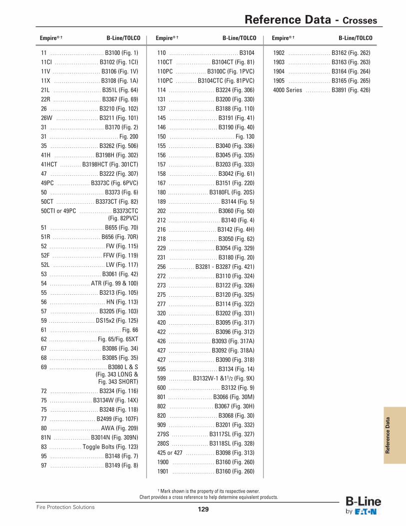
Reference Data
Reference Data - Crosses
129Fire Protection Solutions
11 . . . . . . . . . . . . . . . . . . . . . . . . . . . . B3100 (Fig. 1)11CI . . . . . . . . . . . . . . . . . . . . . . . B3102 (Fig. 1CI)11V . . . . . . . . . . . . . . . . . . . . . . . . . B3106 (Fig. 1V)11X . . . . . . . . . . . . . . . . . . . . . . . . B3108 (Fig. 1A)21L . . . . . . . . . . . . . . . . . . . . . . . . . B351L (Fig. 64)22R . . . . . . . . . . . . . . . . . . . . . . . . . B3367 (Fig. 69)26 . . . . . . . . . . . . . . . . . . . . . . . . . B3210 (Fig. 102)26W . . . . . . . . . . . . . . . . . . . . . . B3211 (Fig. 101)31 . . . . . . . . . . . . . . . . . . . . . . . . . . . . B3170 (Fig. 2)31 . . . . . . . . . . . . . . . . . . . . . . . . . . . . . . . . . . . . Fig. 20035 . . . . . . . . . . . . . . . . . . . . . . . . . B3262 (Fig. 506)41H . . . . . . . . . . . . . . . . . . . . . B3198H (Fig. 302)41HCT . . . . . . . . . . . B3198HCT (Fig. 301CT)47 . . . . . . . . . . . . . . . . . . . . . . . . . B3222 (Fig. 307)49PC . . . . . . . . . . . . . . . . . B3373C (Fig. 6PVC)50 . . . . . . . . . . . . . . . . . . . . . . . . . . . . B3373 (Fig. 6)50CT . . . . . . . . . . . . . . . . . . . . B3373CT (Fig. 82)50CTI or 49PC . . . . . . . . . . . . . . . . . B3373CTC
(Fig. 82PVC)51 . . . . . . . . . . . . . . . . . . . . . . . . . . . . B655 (Fig. 70)51R . . . . . . . . . . . . . . . . . . . . . . . . . B656 (Fig. 70R)52 . . . . . . . . . . . . . . . . . . . . . . . . . . . . . FW (Fig. 115)52F . . . . . . . . . . . . . . . . . . . . . . . . . . FFW (Fig. 119)52L . . . . . . . . . . . . . . . . . . . . . . . . . . . LW (Fig. 117)53 . . . . . . . . . . . . . . . . . . . . . . . . . . . B3061 (Fig. 42)54 . . . . . . . . . . . . . . . . . . . . . ATR (Fig. 99 & 100)55 . . . . . . . . . . . . . . . . . . . . . . . . . B3213 (Fig. 105)56 . . . . . . . . . . . . . . . . . . . . . . . . . . . . . HN (Fig. 113)57 . . . . . . . . . . . . . . . . . . . . . . . . . B3205 (Fig. 103)59 . . . . . . . . . . . . . . . . . . . . . . . . DS15x2 (Fig. 125)61 . . . . . . . . . . . . . . . . . . . . . . . . . . . . . . . . . . . . . Fig. 6662 . . . . . . . . . . . . . . . . . . . . . . . . . Fig. 65/Fig. 65XT67 . . . . . . . . . . . . . . . . . . . . . . . . . . . B3086 (Fig. 34)68 . . . . . . . . . . . . . . . . . . . . . . . . . . . B3085 (Fig. 35)69 . . . . . . . . . . . . . . . . . . . . . . . . . . . . . . B3080 L & S
(Fig. 343 LONG &Fig. 343 SHORT)
72 . . . . . . . . . . . . . . . . . . . . . . . . . B3234 (Fig. 116)75 . . . . . . . . . . . . . . . . . . . . . . B3134W (Fig. 14X)75 . . . . . . . . . . . . . . . . . . . . . . . . . B3248 (Fig. 118)77 . . . . . . . . . . . . . . . . . . . . . . . . B2499 (Fig. 107F)80 . . . . . . . . . . . . . . . . . . . . . . . . . . AWA (Fig. 209)81N . . . . . . . . . . . . . . . . . . . B3014N (Fig. 309N)83 . . . . . . . . . . . . . . . . . Toggle Bolts (Fig. 123)95 . . . . . . . . . . . . . . . . . . . . . . . . . . . . B3148 (Fig. 7)97 . . . . . . . . . . . . . . . . . . . . . . . . . . . . B3149 (Fig. 8)
110 . . . . . . . . . . . . . . . . . . . . . . . . . . . . . . . . . . . . B3104110CT . . . . . . . . . . . . . . . . . . B3104CT (Fig. 81)110PC . . . . . . . . . . . . . . . . B3100C (Fig. 1PVC)110PC . . . . . . . . . . . B3104CTC (Fig. 81PVC)114 . . . . . . . . . . . . . . . . . . . . . . . . B3224 (Fig. 306)131 . . . . . . . . . . . . . . . . . . . . . . . . B3200 (Fig. 330)137 . . . . . . . . . . . . . . . . . . . . . . . . B3188 (Fig. 110)145 . . . . . . . . . . . . . . . . . . . . . . . . . B3191 (Fig. 41)146 . . . . . . . . . . . . . . . . . . . . . . . . . B3190 (Fig. 40)150 . . . . . . . . . . . . . . . . . . . . . . . . . . . . . . . . . . Fig. 130155 . . . . . . . . . . . . . . . . . . . . . . . . B3040 (Fig. 336)156 . . . . . . . . . . . . . . . . . . . . . . . . B3045 (Fig. 335)157 . . . . . . . . . . . . . . . . . . . . . . . . B3203 (Fig. 333)158 . . . . . . . . . . . . . . . . . . . . . . . . . B3042 (Fig. 61)167 . . . . . . . . . . . . . . . . . . . . . . . . B3151 (Fig. 220)180 . . . . . . . . . . . . . . . . . . . . . B3180FL (Fig. 20S)189 . . . . . . . . . . . . . . . . . . . . . . . . . . . B3144 (Fig. 5)202 . . . . . . . . . . . . . . . . . . . . . . . . . B3060 (Fig. 50)212 . . . . . . . . . . . . . . . . . . . . . . . . . . . B3140 (Fig. 4)216 . . . . . . . . . . . . . . . . . . . . . . . . . B3142 (Fig. 4H)218 . . . . . . . . . . . . . . . . . . . . . . . . . B3050 (Fig. 62)229 . . . . . . . . . . . . . . . . . . . . . . . . B3054 (Fig. 329)231 . . . . . . . . . . . . . . . . . . . . . . . . . B3180 (Fig. 20)256 . . . . . . . . . . . . . B3281 - B3287 (Fig. 421)272 . . . . . . . . . . . . . . . . . . . . . . . . B3110 (Fig. 324)273 . . . . . . . . . . . . . . . . . . . . . . . . B3122 (Fig. 326)275 . . . . . . . . . . . . . . . . . . . . . . . . B3120 (Fig. 325)277 . . . . . . . . . . . . . . . . . . . . . . . . B3114 (Fig. 322)320 . . . . . . . . . . . . . . . . . . . . . . . . B3202 (Fig. 331)420 . . . . . . . . . . . . . . . . . . . . . . . . B3095 (Fig. 317)422 . . . . . . . . . . . . . . . . . . . . . . . . B3096 (Fig. 312)426 . . . . . . . . . . . . . . . . . . . . . . B3093 (Fig. 317A)427 . . . . . . . . . . . . . . . . . . . . . . B3092 (Fig. 318A)427 . . . . . . . . . . . . . . . . . . . . . . . . B3090 (Fig. 318)595 . . . . . . . . . . . . . . . . . . . . . . . . . B3134 (Fig. 14)599 . . . . . . . . . . . . B3132W-1 &11/2 (Fig. 9X)600 . . . . . . . . . . . . . . . . . . . . . . . . . . . B3132 (Fig. 9)801 . . . . . . . . . . . . . . . . . . . . . . . B3066 (Fig. 30M)802 . . . . . . . . . . . . . . . . . . . . . . . B3067 (Fig. 30H)820 . . . . . . . . . . . . . . . . . . . . . . . . . B3068 (Fig. 30)909 . . . . . . . . . . . . . . . . . . . . . . . . B3201 (Fig. 332)279S . . . . . . . . . . . . . . . . . . . B3117SL (Fig. 327)280S . . . . . . . . . . . . . . . . . . . B3118SL (Fig. 328)425 or 427 . . . . . . . . . . . . . . . B3098 (Fig. 313)1900 . . . . . . . . . . . . . . . . . . . . . . B3160 (Fig. 260)1901 . . . . . . . . . . . . . . . . . . . . . . B3160 (Fig. 260)
1902 . . . . . . . . . . . . . . . . . . . . . . B3162 (Fig. 262)1903 . . . . . . . . . . . . . . . . . . . . . . B3163 (Fig. 263)1904 . . . . . . . . . . . . . . . . . . . . . . B3164 (Fig. 264)1905 . . . . . . . . . . . . . . . . . . . . . . B3165 (Fig. 265)4000 Series . . . . . . . . . . . . . B3891 (Fig. 426)
Empire® † B-Line/TOLCO Empire® † B-Line/TOLCO Empire® † B-Line/TOLCO
† Mark shown is the property of its respective owner.Chart provides a cross reference to help determine equivalent products.
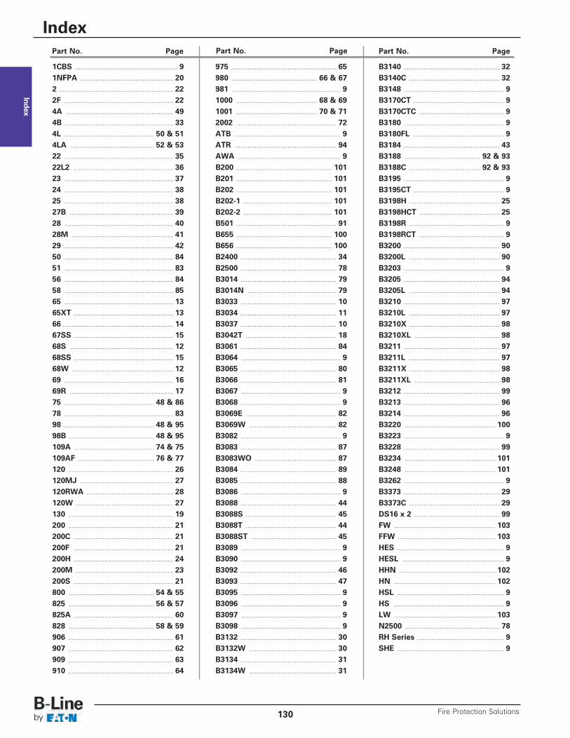
Index
1CBS ........................................................ 91NFPA ................................................... 202 ............................................................... 222F ............................................................ 224A ........................................................... 494B ............................................................ 334L .................................................. 50 & 514LA .............................................. 52 & 5322 ............................................................ 3522L2 ....................................................... 3623 ............................................................ 3724 ............................................................ 3825 ............................................................ 3827B ......................................................... 3928 ............................................................ 4028M ........................................................ 4129 ............................................................ 4250 ............................................................ 8451 ............................................................ 8356 ............................................................ 8458 ............................................................ 8565 ............................................................ 1365XT ....................................................... 1366 ............................................................. 1467SS ....................................................... 1568S ......................................................... 1268SS ....................................................... 1568W ........................................................ 1269 ............................................................ 1669R ......................................................... 1775 .................................................. 48 & 8678 ............................................................ 8398 .................................................. 48 & 9598B ............................................... 48 & 95109A ............................................ 74 & 75109AF .......................................... 76 & 77120 .......................................................... 26120MJ ................................................... 27120RWA ................................................ 28120W ...................................................... 27130 .......................................................... 19200 .......................................................... 21200C ....................................................... 21200F ....................................................... 21200H ....................................................... 24200M ...................................................... 23200S ....................................................... 21800 ............................................... 54 & 55825 ............................................... 56 & 57825A ....................................................... 60828 ............................................... 58 & 59906 .......................................................... 61907 .......................................................... 62909 .......................................................... 63910 .......................................................... 64
975 .......................................................... 65980 ............................................... 66 & 67981 ............................................................ 91000 ............................................. 68 & 691001 ............................................. 70 & 712002 ....................................................... 72ATB ........................................................... 9ATR ........................................................ 94AWA ......................................................... 9B200 ..................................................... 101B201 ..................................................... 101B202 ..................................................... 101B202-1 ................................................. 101B202-2 ................................................. 101B501 ....................................................... 91B655 ..................................................... 100B656 ..................................................... 100B2400 ..................................................... 34B2500 ..................................................... 78B3014 ..................................................... 79B3014N ................................................. 79B3033 ..................................................... 10B3034 ..................................................... 11B3037 ..................................................... 10B3042T .................................................. 18B3061 ..................................................... 84B3064 ....................................................... 9B3065 ..................................................... 80B3066 ..................................................... 81B3067 ....................................................... 9B3068 ....................................................... 9B3069E .................................................. 82B3069W ................................................ 82B3082 ....................................................... 9B3083 ..................................................... 87B3083WO ............................................. 87B3084 ..................................................... 89B3085 ..................................................... 88B3086 ....................................................... 9B3088 ..................................................... 44B3088S .................................................. 45B3088T .................................................. 44B3088ST ............................................... 45B3089 ....................................................... 9B3090 ....................................................... 9B3092 ..................................................... 46B3093 ..................................................... 47B3095 ....................................................... 9B3096 ....................................................... 9B3097 ....................................................... 9B3098 ....................................................... 9B3132 ..................................................... 30B3132W ................................................ 30B3134 ..................................................... 31B3134W ................................................ 31
B3140 ..................................................... 32B3140C .................................................. 32B3148 ....................................................... 9B3170CT .................................................. 9B3170CTC ............................................... 9B3180 ....................................................... 9B3180FL .................................................. 9B3184 ..................................................... 43B3188 .......................................... 92 & 93B3188C ....................................... 92 & 93B3195 ....................................................... 9B3195CT .................................................. 9B3198H .................................................. 25B3198HCT ............................................ 25B3198R .................................................... 9B3198RCT ............................................... 9B3200 ..................................................... 90B3200L .................................................. 90B3203 ....................................................... 9B3205 ..................................................... 94B3205L .................................................. 94B3210 ..................................................... 97B3210L .................................................. 97B3210X .................................................. 98B3210XL ............................................... 98B3211 ..................................................... 97B3211L .................................................. 97B3211X .................................................. 98B3211XL ............................................... 98B3212 ..................................................... 99B3213 ..................................................... 96B3214 ..................................................... 96B3220 .................................................. 100B3223 ....................................................... 9B3228 ..................................................... 99B3234 .................................................. 101B3248 .................................................. 101B3262 ....................................................... 9B3373 ..................................................... 29B3373C .................................................. 29DS16 x 2 ............................................... 99FW ........................................................ 103FFW ...................................................... 103HES ........................................................... 9HESL ........................................................ 9HHN ..................................................... 102HN ........................................................ 102HSL ........................................................... 9HS ............................................................. 9LW ........................................................ 103N2500 .................................................... 78RH Series ................................................ 9SHE ........................................................... 9
Part No. Page Part No. Page Part No. Page
Index
Fire Protection Solutions130

Fire Protection Solutions
Eaton’s B-Line Business reserves the right to make changes to the specifications, materials, equipment, prices,or the availability of products at any time without prior notice. While every effort has been made to assure theaccuracy of information contained in this catalog at the time of publication, we cannot accept responsibility
for inaccuracies resulting from undetected errors or omissions.

Eaton’s B-Line Business Eaton’s B-Line BusinessUnited States United Kingdom509 West Monroe Street Walrow Industrial EstateHighland, IL 62249 Somerset, TA9 4AQUnited States United KingdomPhone: (800) 851-7415 Phone: (44) 1278 772600www.cooperbline.com/contactus www.cooperbline.com/contactuk
Eaton’s B-Line Business Eaton’s B-Line BusinessCanada Middle East5925 McLaughlin Road PO Box 70160 - Al Khobar - 31952Mississauga, ON L5R 1B8 Kingdom of Saudi ArabiaCanada Phone: 00966 3 812 2236Phone: (800) 569-3660 www.cooperbline.com/contactmewww.cooperbline.com/contactca
Eaton1000 Eaton BoulevardCleveland, OH 44122United StatesEaton.com
Eaton’s B-Line Business509 West Monroe StreetHighland, IL 62249Phone: 800-851-7415Fax: 618-654-1917www.bline.com
© 2013 Eaton All Rights Reserved Eaton is a registered trademarkPrinted in USA Publication No. FPS-13 All other trademarks are propertyDecember 2013 20M of their respective owners.
U.S. Customer Service Center is staffed Monday through Fridayfrom 7 a.m. to 5:00 p.m. Central Standard Time.For more information, visit www.cooperbline.com/fireprotection.