Embed Size (px)
Citation preview
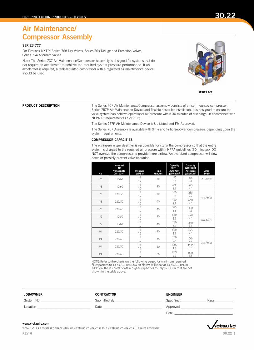
PRODUCT DESCRIPTION The Series 7C7 Air Maintenance/Compressor assembly consists of a riser-mounted compressor, Series 757P Air Maintenance Device and flexible hoses for installation. It is designed to ensure the valve system can achieve operational air pressure within 30 minutes of discharge, in accordance with NFPA 13 requirements (7.2.6.2.2).
The Series 757P Air Maintenance Device is UL Listed and FM Approved.
The Series 7C7 Assembly is available with 1/6, 1/3 and 1/2 horsepower compressors depending upon the system requirements.
For FireLock NXT™ Series 768 Dry Valves, Series 769 Deluge and Preaction Valves, Series 764 Alternate Valves.
Note: The Series 7C7 Air Maintenance/Compressor Assembly is designed for systems that do not require an accelerator to achieve the required system pressure performance. If an accelerator is required, a tank-mounted compressor with a regulated air maintenance device should be used.
COMPRESSOR CAPACITIES
The engineer/system designer is responsible for sizing the compressor so that the entire system is charged to the required air pressure within NFPA guidelines (30 minutes). DO NOT oversize the compressor to provide more airflow. An oversized compressor will slow down or possibly prevent valve operation.
Hp
Nominal AC
Voltage/Hz (+/- 10%)
Pressurepsi/Bar
TimeMinutes
CapacityWITH
AutoVentgallons/m3
CapacityWITHOUTAutoVent
gallons/m3AmpDraw
1/6 110/6018 30 175 275 2.1 Amps1.2 0.7 1.1
1/3 110/6018 30 375 525
4.4 Amps
1.2 1.4 2.0
1/3 220/5018 30 160 2351.2 0.6 0.9
1/3 220/5018 60 450 6601.2 1.7 2.5
1/3 220/6018
30370 400
1.51.2 1.4
1/2 110/5018 30 660 670
6.6 Amps1.2 2.5 2.5
1/2 110/6018
30780 830
3.11.2 3.0
3/4 220/5018 30 600 675
3.8 Amps
1.2 2.3 2.5
3/4 220/6018
30700 775
2.91.2 2.7
3/4 220/5018
601200 1350
5.01.2 4.5
3/4 220/6018
601375 1525
5.81.2 5.2
NOTE: Refer to the charts on the following pages for minimum requiredfill capacities to 13 psi/0.9 Bar. Low air alarms will clear at 13 psi/0.9 Bar. Inaddition, these charts contain higher capacities to 18 psi/1.2 Bar that are notshown in the table above.
30.22_1
Air Maintenance/ Compressor AssemblySERIES 7C7
30.22FIRE PROTECTION PRODUCTS – DEVICES
JOB/OWNER CONTRACTOR ENGINEER
System No. ______________________________ Submitted By ____________________________ Spec Sect _______________ Para ___________
Location ________________________________ Date ___________________________________ Approved _______________________________
Date ___________________________________
www.victaulic.comVICTAULIC IS A REGISTERED TRADEMARK OF VICTAULIC COMPANY. © 2013 VICTAULIC COMPANY. ALL RIGHTS RESERVED.
REV_G
SERIES 7C7
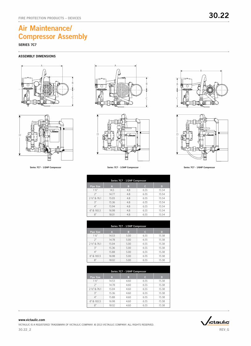
ASSEMBLY DIMENSIONS
Series 7C7 - 1/3HP Compressor
Pipe Size A B C D
1 1/2” 14.53 5.00 6.55 15.382” 14.78 5.00 6.55 15.38
2 1/2” & 76.1 15.04 5.00 6.55 15.383” 15.36 5.00 6.55 15.384” 15.88 5.00 6.55 15.38
6” & 165.5 16.98 5.00 6.55 15.388” 18.02 5.00 6.55 15.38
Series 7C7 - 1/3HP Compressor Series 7C7 - 1/6HP Compressor
Series 7C7 - 1/6HP Compressor
Pipe Size A B C D
1 1/2” 14.53 4.60 6.55 15.382” 14.78 4.60 6.55 15.38
2 1/2” & 76.1 15.04 4.60 6.55 15.383” 15.36 4.60 6.55 15.384” 15.88 4.60 6.55 15.38
6” & 165.5 16.98 4.60 6.55 15.388” 18.02 4.60 6.55 15.38
A
B
C
D
A
B
C
DD
A
B
C
Series 7C7 - 1/2HP Compressor
Pipe Size A B C D
1 1/2” 14.5 4.8 6.55 15.542” 14.77 4.8 6.55 15.54
2 1/2” & 76.1 15.03 4.8 6.55 15.543” 15.36 4.8 6.55 15.544” 15.94 4.8 6.55 15.54
6” & 165.5 16.98 4.8 6.55 15.548” 18.01 4.8 6.55 15.54
Series 7C7 - 1/2HP Compressor
30.22
30.22_2
FIRE PROTECTION PRODUCTS – DEVICES
Air Maintenance/ Compressor Assembly
www.victaulic.comVICTAULIC IS A REGISTERED TRADEMARK OF VICTAULIC COMPANY. © 2013 VICTAULIC COMPANY. ALL RIGHTS RESERVED.
REV_G
SERIES 7C7
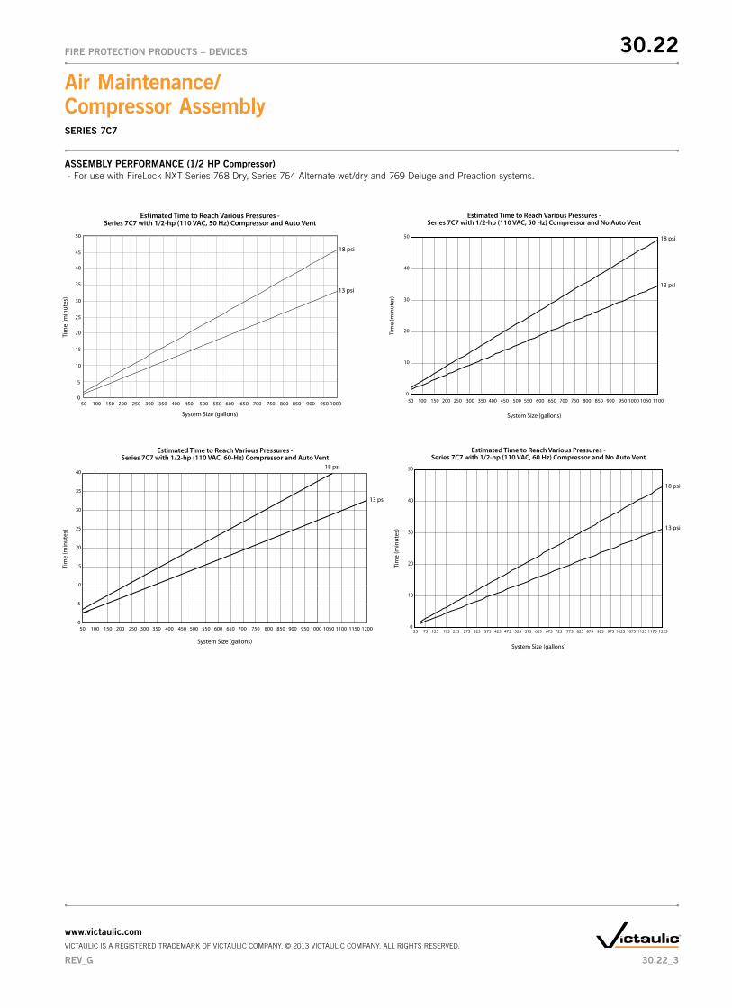
ASSEMBLY PERFORMANCE (1/2 HP Compressor) - For use with FireLock NXT Series 768 Dry, Series 764 Alternate wet/dry and 769 Deluge and Preaction systems.
18 psi
13 psi
System Size (gallons)
Tim
e (m
inut
es)
Estimated Time to Reach Various Pressures -Series 7C7 with 1/2-hp (110 VAC, 50 Hz) Compressor and Auto Vent
0
5
10
15
20
25
30
35
40
50 100 150 200 250 300 350 400 450 500 550 600 650 700 750 800 850 900 950 1000
45
50
18 psi
13 psi
System Size (gallons)
Tim
e (m
inut
es)
Estimated Time to Reach Various Pressures -Series 7C7 with 1/2-hp (110 VAC, 60-Hz) Compressor and Auto Vent
0
5
10
15
20
25
30
35
40
50 100 150 200 250 300 350 400 450 500 550 600 650 700 750 800 850 900 950 1000 1050 1100 1150 1200
0
10
20
30
40
50 18 psi
13 psi
System Size (gallons)
Tim
e (m
inut
es)
Estimated Time to Reach Various Pressures -Series 7C7 with 1/2-hp (110 VAC, 50 Hz) Compressor and No Auto Vent
50 100 150 200 250 300 350 400 450 500 550 600 650 700 750 800 850 900 950 1000 1050 1100
0
10
20
30
40
50
18 psi
13 psi
System Size (gallons)
Tim
e (m
inut
es)
Estimated Time to Reach Various Pressures -Series 7C7 with 1/2-hp (110 VAC, 60 Hz) Compressor and No Auto Vent
25 75 125 175 225 275 325 375 425 475 525 575 625 675 725 775 825 875 925 975 1025 1075 1125 1175 1225
30.22
30.22_3
FIRE PROTECTION PRODUCTS – DEVICES
Air Maintenance/ Compressor Assembly
www.victaulic.comVICTAULIC IS A REGISTERED TRADEMARK OF VICTAULIC COMPANY. © 2013 VICTAULIC COMPANY. ALL RIGHTS RESERVED.
REV_G
SERIES 7C7
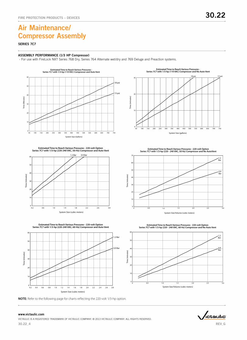
ASSEMBLY PERFORMANCE (1/3 HP Compressor) - For use with FireLock NXT Series 768 Dry, Series 764 Alternate wet/dry and 769 Deluge and Preaction systems.
0
10
20
30
40
50
60
System Size (cubic meters)
Tim
e (m
inut
es)
0.6 1.0 1.4 1.80.2 2.2 2.6 3.0
1.2 Bar 0.9 Bar
Estimated Time to Reach Various Pressures - 220-volt OptionSeries 7C7 with 1/3-hp (220-240 VAC, 50-Hz) Compressor and Auto Vent
0
10
20
30
40
50
60
System Size (cubic meters)
Tim
e (m
inut
es)
0.2 0.4 0.6 0.8 1.0 1.2 1.4 1.6 1.8 2.0 2.2 2.4 2.6 2.8
1.2 Bar
0.9 Bar
Estimated Time to Reach Various Pressures - 220-volt OptionSeries 7C7 with 1/3-hp (220-240 VAC, 60-Hz) Compressor and Auto Vent
0
10
20
30
40
50
60
70
Estimated Time to Reach Various Pressures - 220-volt OptionSeries 7C7 with 1/3-hp (220 - 240 VAC, 50 Hz) Compressor and No AutoVent
Tim
e (m
inut
es)
System Size/Volume (cubic meters)
0 0.5 1.0 1.5 2.0 2.5 3.0
1.2 Bar
0.9 Bar
0
10
20
30
40
50
60
Estimated Time to Reach Various Pressures - 220-volt OptionSeries 7C7 with 1/3-hp (220 - 240 VAC, 60 Hz) Compressor and No Auto Vent
0 0.5 1.0 1.5 2.0 2.5 3.0
Tim
e (m
inut
es)
System Size/Volume (cubic meters)
1.2 Bar
0.9 Bar
0
10
20
30
40
50
60
System Size (Gallons)
Tim
e (M
inut
es)
50 100 150 200 250 300 350 400 450 500 550 600 650 700 750
Estimated Time to Reach Various Pressures - Series 7C7 with 1/3-hp (110 VAC) Compressor and Auto Vent
13 psi
18 psi
50 100 150 200 250 300 350 400 450 500 550 600 650 700 7500
10
20
3018 psi 13 psi
Estimated Time to Reach Various Pressures -Series 7C7 with 1/3-hp (110 VAC) Compressor and No Auto Vent
System Size (gallons)
Tim
e (m
inut
es)
NOTE: Refer to the following page for charts reflecting the 220-volt 1/3-hp option.
30.22
30.22_4
FIRE PROTECTION PRODUCTS – DEVICES
Air Maintenance/ Compressor Assembly
www.victaulic.comVICTAULIC IS A REGISTERED TRADEMARK OF VICTAULIC COMPANY. © 2013 VICTAULIC COMPANY. ALL RIGHTS RESERVED.
REV_G
SERIES 7C7
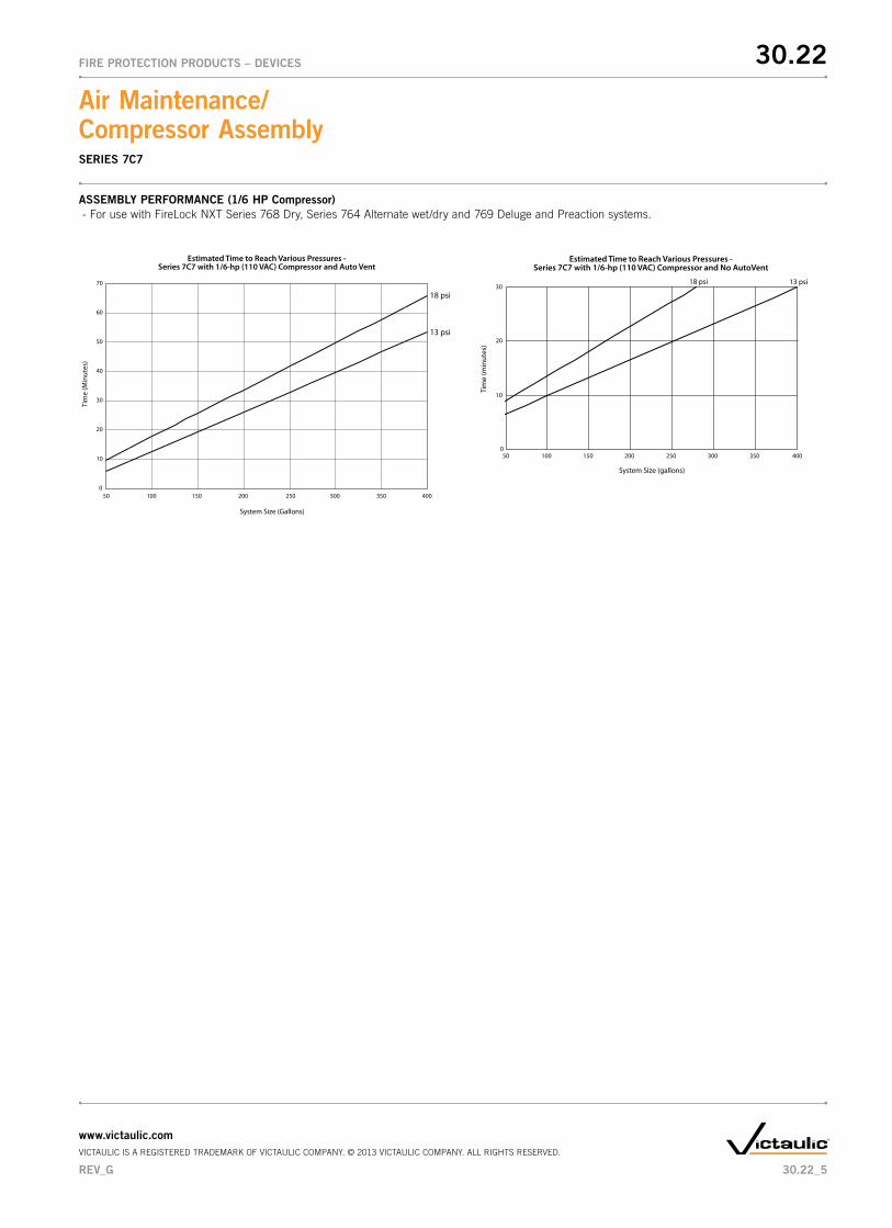
0
10
20
30
40
50
60
70
System Size (Gallons)
Tim
e (M
inut
es)
50 100 150 200 250 300 350 400
Estimated Time to Reach Various Pressures - Series 7C7 with 1/6-hp (110 VAC) Compressor and Auto Vent
13 psi
18 psi
50 100 150 200 250 300 350 4000
10
20
3018 psi 13 psi
Estimated Time to Reach Various Pressures -Series 7C7 with 1/6-hp (110 VAC) Compressor and No AutoVent
System Size (gallons)
Tim
e (m
inut
es)
ASSEMBLY PERFORMANCE (1/6 HP Compressor) - For use with FireLock NXT Series 768 Dry, Series 764 Alternate wet/dry and 769 Deluge and Preaction systems.
30.22
30.22_5
FIRE PROTECTION PRODUCTS – DEVICES
Air Maintenance/ Compressor Assembly
www.victaulic.comVICTAULIC IS A REGISTERED TRADEMARK OF VICTAULIC COMPANY. © 2013 VICTAULIC COMPANY. ALL RIGHTS RESERVED.
REV_G
SERIES 7C7
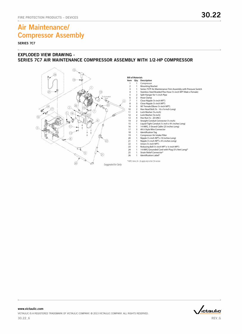
ExPLODED VIEW DRAWING - SERIES 7C7 AIR MAINTENANCE COMPRESSOR ASSEMBLY WITH 1/2-HP COMPRESSOR
1
4
23
6
14 2
3
107
14
11
To ActuatorTrim
9
8
5
15
1925
24
18
16
17
12
13
20
21
22
26
Bill of MaterialsItem Qty. Description 1 1 Compressor 2 1 Mounting Bracket 3 1 Series 757P Air Maintenance Trim Assembly with Pressure Switch 4 1 Stainless Steel Braided Flex Hose (½-inch NPT Male x Female) 5 2 Split Hanger for ½-inch Pipe 6 2 Hose Clamp 7 1 Close Nipple (¼-inch NPT) 8 3 Close Nipple (½-inch NPT) 9 3 90° Female Elbow (½-inch NPT) 10 2 Hex-Head Bolt (3⁄8 - 16 x 5⁄8-inch Long) 11 4 Lock Washer (5⁄16 inch) 12 2 Lock Washer (3⁄8 inch) 13 4 Hex Nut (¼ - 20 UNC) 14 2 Straight Conduit Connector (½-inch) 15 1 Liquid-Tight Conduit (½ inch x 9½ inches Long) 16 1 14 AWG, 3-Strand Cable (25 inches Long) 17 3 #8 U-Style Wire Connector 18 1 Identi�cation Tag 19 1 Compressor Air Intake Filter 20 1 Nipple (½-inch NPT x 10 inches Long) 21 1 Nipple (½-inch NPT x 4½ inches Long) 22 1 Union (½-inch NPT) 23 1 Reducing Bell (½-inch NPT x ¼-inch NPT) 24 1 14 AWG Grounded Cord with Plug (5½ feet Long)* 25 1 Strain Relief Connector* 26 1 Identi�cation Label*
* NOTE: Items 24 - 26 apply only to the CSA version
Exaggerated for Clarity
30.22
30.22_6
FIRE PROTECTION PRODUCTS – DEVICES
Air Maintenance/ Compressor Assembly
www.victaulic.comVICTAULIC IS A REGISTERED TRADEMARK OF VICTAULIC COMPANY. © 2013 VICTAULIC COMPANY. ALL RIGHTS RESERVED.
REV_G
SERIES 7C7
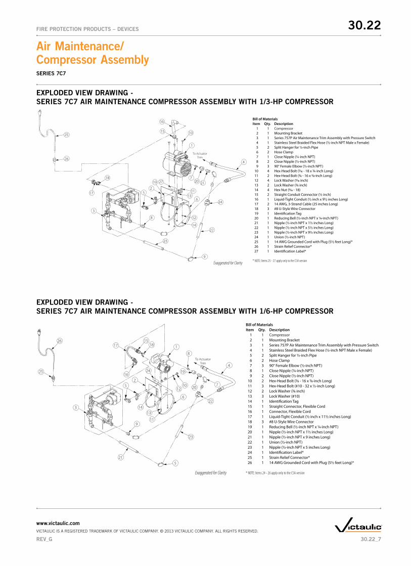
ExPLODED VIEW DRAWING - SERIES 7C7 AIR MAINTENANCE COMPRESSOR ASSEMBLY WITH 1/6-HP COMPRESSOR
1
4
7
5
6
11
13
2
3
8
19
10
To ActuatorTrim
16
9
512
14
1517 18
20
21
22
23
2425
26
Bill of MaterialsItem Qty. Description 1 1 Compressor 2 1 Mounting Bracket 3 1 Series 757P Air Maintenance Trim Assembly with Pressure Switch 4 1 Stainless Steel Braided Flex Hose (½-inch NPT Male x Female) 5 2 Split Hanger for ½-inch Pipe 6 2 Hose Clamp 7 3 90° Female Elbow (½-inch NPT) 8 1 Close Nipple (¼-inch NPT) 9 2 Close Nipple (½-inch NPT) 10 2 Hex-Head Bolt (3⁄8 - 16 x 5⁄8-inch Long) 11 3 Hex-Head Bolt (#10 - 32 x ½-inch Long) 12 2 Lock Washer (3⁄8 inch) 13 3 Lock Washer (#10) 14 1 Identi�cation Tag 15 1 Straight Connector, Flexible Cord 16 1 Connector, Flexible Cord 17 1 Liquid-Tight Conduit (½ inch x 11½ inches Long) 18 3 #8 U-Style Wire Connector 19 1 Reducing Bell (½-inch NPT x ¼-inch NPT) 20 1 Nipple (½-inch NPT x 1½ inches Long) 21 1 Nipple (½-inch NPT x 9 inches Long) 22 1 Union (½-inch NPT) 23 1 Nipple (½-inch NPT x 5 inches Long) 24 1 Identi�cation Label* 25 1 Strain Relief Connector* 26 1 14 AWG Grounded Cord with Plug (5½ feet Long)*
* NOTE: Items 24 - 26 apply only to the CSA versionExaggerated for Clarity
ExPLODED VIEW DRAWING - SERIES 7C7 AIR MAINTENANCE COMPRESSOR ASSEMBLY WITH 1/3-HP COMPRESSOR
1
4
25
6
23
2
3
7
To ActuatorTrim
9
8
5
10
11
12
13
14
15
16
17
1819 20 21
22
24
26
27
Bill of MaterialsItem Qty. Description 1 1 Compressor 2 1 Mounting Bracket 3 1 Series 757P Air Maintenance Trim Assembly with Pressure Switch 4 1 Stainless Steel Braided Flex Hose (½-inch NPT Male x Female) 5 2 Split Hanger for ½-inch Pipe 6 2 Hose Clamp 7 1 Close Nipple (¼-inch NPT) 8 2 Close Nipple (½-inch NPT) 9 3 90° Female Elbow (½-inch NPT) 10 4 Hex-Head Bolt (5⁄16 - 18 x ¾-inch Long) 11 2 Hex-Head Bolt (3⁄8 - 16 x 5⁄8-inch Long) 12 4 Lock Washer (5⁄16 inch) 13 2 Lock Washer (3⁄8 inch) 14 4 Hex Nut (5⁄16 - 18) 15 2 Straight Conduit Connector (½ inch) 16 1 Liquid-Tight Conduit (½ inch x 9½ inches Long) 17 2 14 AWG, 3-Strand Cable (25 inches Long) 18 3 #8 U-Style Wire Connector 19 1 Identi�cation Tag 20 1 Reducing Bell (½-inch NPT x ¼-inch NPT) 21 1 Nipple (½-inch NPT x 1½ inches Long) 22 1 Nipple (½-inch NPT x 5½ inches Long) 23 1 Nipple (½-inch NPT x 9½ inches Long) 24 1 Union (½-inch NPT) 25 1 14 AWG Grounded Cord with Plug (5½ feet Long)* 26 1 Strain Relief Connector* 27 1 Identi�cation Label*
* NOTE: Items 25 - 27 apply only to the CSA versionExaggerated for Clarity
30.22
30.22_7
FIRE PROTECTION PRODUCTS – DEVICES
Air Maintenance/ Compressor Assembly
www.victaulic.comVICTAULIC IS A REGISTERED TRADEMARK OF VICTAULIC COMPANY. © 2013 VICTAULIC COMPANY. ALL RIGHTS RESERVED.
REV_G
SERIES 7C7
WARNING
�•� This�product�must�be�installed�by�an�experienced,�trained�installer,�in�accordance�with�the�instructions�provided�with�each�valve.�These� instructions contain important information.
Failure�to�follow�these�instructions�may�result�in�serious�personal�injury,�property�damage,�or�valve�leakage.
If�you�need�additional�copies�of�this�product�literature�or�the�valve��installation�instructions,�or�if�you�have�any�questions�about�the�safe�installation�and�use�of�this�device,�contact�Victaulic�Company,�P.O.�Box�31,�Easton,�PA�18044-0031�USA,�Telephone:�001-610-559-3300.
WARNING
WARRANTY Refer to the Warranty section of the current Price List or contact Victaulic for details.
This product shall be manufactured by Victaulic or to Victaulic specifications. All products to be installed in accordance with current Victaulic installation/assembly instructions. Victaulic reserves the right to change product specifications, designs and standard equipment without notice and without incurring obligations.
NOTE
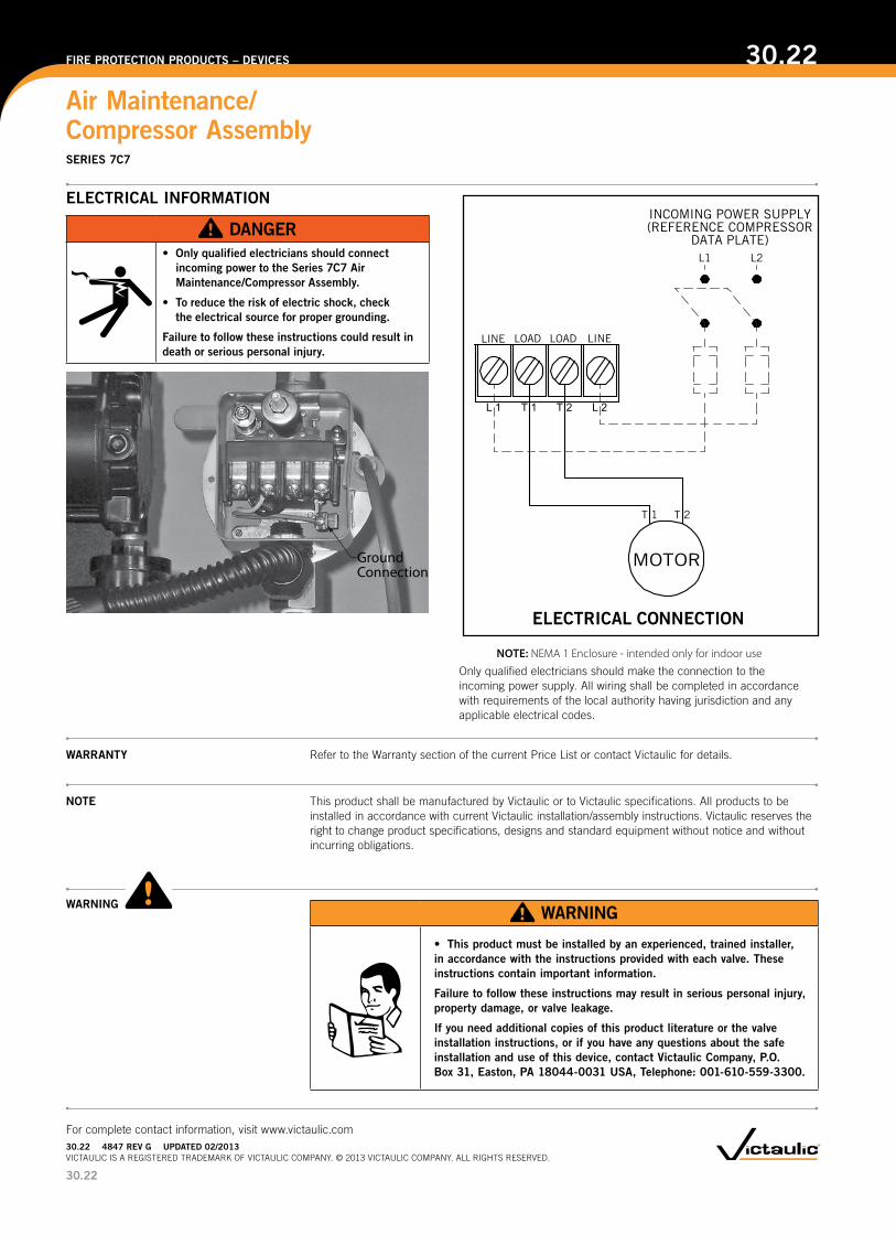
ELECTRICAL INFORMATION
DANGER•� Only�qualified�electricians�should�connect�
incoming�power�to�the�Series�7C7�Air�Maintenance/Compressor Assembly.
•� To�reduce�the�risk�of�electric�shock,�check�the�electrical�source�for�proper�grounding.
Failure�to�follow�these�instructions�could�result�in�death�or�serious�personal�injury.
Ground Connection
ELECTRICAL CONNECTION
LINE LOAD LINELOAD
L1 L2
L 1 T 1 T 2 L 2
T 1 T 2
MOTOR
INCOMING POWER SUPPLY(REFERENCE COMPRESSOR
DATA PLATE)
NOTE: NEMA 1 Enclosure - intended only for indoor use
Only qualified electricians should make the connection to the incoming power supply. All wiring shall be completed in accordance with requirements of the local authority having jurisdiction and any applicable electrical codes.
30.22
Air Maintenance/ Compressor Assembly
30.22FIRE PROTECTION PRODUCTS – DEVICES
For complete contact information, visit www.victaulic.com30.22����4847�REV G UPDATED 02/2013VICTAULIC IS A REGISTERED TRADEMARK OF VICTAULIC COMPANY. © 2013 VICTAULIC COMPANY. ALL RIGHTS RESERVED.
SERIES 7C7