Embed Size (px)
Citation preview

Fire protection in NPP: Challenges posed by fires to the
Structures, Systems and Components of Nuclear Power
Plants
Summary Report
Christiane Bruynooghe, Andrea Bucalossi
DG JRC – Institute for Energy 2007
EUR- 23231 EN
Safety of Nuclear Installations
Institute for Energy

Mission of the Institute for Energy The Institute for Energy provides scientific and technical support for the conception, development, implementation and monitoring of community policies related to energy. Special emphasis is given to the security of energy supply and to sustainable and safe energy production. European Commission Joint Research Centre (JRC) http://ec.europa.eu/dgs/jrc/index.cfm Institute for Energy, Petten (the Netherlands) http://ie.jrc.ec.europa.eu/ Contact information: Christiane Bruynooghe Address: Postbus 2, 1755 ZG Petten, the Nederlands E-Mail: [email protected] Tel: + 31 22 456 5013 Fax: + 31 22 456 5637 http://ec.europa.eu/dgs/jrc/index.cfm http://ie.jrc.ec.europa.eu/
Legal Notice Neither the European Commission nor any person acting on behalf of the Commission is responsible for the use, which might be made of this publication. A great deal of additional information on the European Union is available on the Internet. It can be accessed through the Europa server http://europa.eu EUR 23231 EN ISSN 1018-5593 Luxembourg: Office for Official Publications of the European Communitie © European Communities, 2008 Reproduction is authorised provided the source is acknowledged. Printed in the Netherlands

Fire protection in NPP: Challenges posed by fires to the
Structures, Systems and Components of Nuclear Power
Plants
Christiane Bruynooghe, Andrea Bucalossi
JRC – Institute for Energy

SONIS - Safety of Nuclear Installation

SONIS - Safety of Nuclear Installation
Page 1/38
EXECUTIVE SUMARY
This Report summarizes the results of the studies performed by the JRC/IE in 2007 on Task 2 of the SONIS research program which is devoted to the Safety of Nuclear Installations. The aim of this task is to identify the fire related parameters associated to the design basis scenarios for accidental and deliberate events, and to identify the Structures, Systems, and Components (SSCs) where the vulnerabilities are important for the overall safety evaluation of the plants.
Target beneficiaries of this study are member states regulatory bodies who will find a state of the art of fire resistance standards for SSCs at Nuclear Power Plants as well as EC General Directions which promote international agreement on safety standards.
Today it is still difficult to determine fire resistance parameters for certain plant components, in particular for electrical and I&C components. In this study a subset of SSCs has been selected independently from the origin of the fire, namely the most relevant electrical components and those which ensure compartment tightness. Their fire resistance is fundamental in making assumptions for Fire Probabilistic Safety Assessment studies and for the conclusion of such studies.
This report also collects information on norms and standards relevant to fire safety as well as their corresponding fire resistance tests for electrical cables and electrical cabinets.
Fire doors, fire dampers and fire seals to ensure compartment tightness were not considered in the same comprehensive way but the norms, standards and corresponding tests were also listed when available.
The information presented in this document has two fields of application:
• improvement of Fire PSA assumptions relevant to component behaviour;
• comparison of norms that can facilitate selection of components in case of fire safety upgrading or equipment refurbishment programs.
The component fire resistance has been widely identified as a fundamental issue and is currently supported by several national or international ambitious experimental programs. This report prepares the next step of the SONIS program which will consist in estimating (together with the main key stakeholders in the “fire” community from Europe, the OECD countries, the Russian Federation and Ukraine):

SONIS - Safety of Nuclear Installation
Page 2/38
• to which extent national norms and standards consider the requirements on SSCs and fire barriers of nuclear power plants;
• if experimental programs are mature enough to allow fire resistance test definition for SSCs without appropriate certificates.
This work will be continued in 2008.

SONIS - Safety of Nuclear Installation
Page 3/38
Table of Contents 1 INTRODUCTION .......................................................................................... 5
2 LARGE FIRE SCENARIOS AND EQUIPMENT CONCERNED ................... 7
3 DEFICIENCIES IDENTIFIED BY EXPERIMENTAL PROGRAMS ............. 10
3.1 CABLES AND WIRES..................................................................................................................10 3.2 ELECTRICAL CABINETS.............................................................................................................12
4 EQUIPMENT FIRE RESISTANCE TESTS................................................. 17
4.1 ELECTRICAL CABLES ...............................................................................................................18 4.1.1 IEC 60331-x: Tests for electric cables under fire conditions - Circuit integrity (Ref [S1], [S2], [S3]).........................................................................................................................................19 4.1.2 IEC 60332 Part 1, Part 2, Part 3: Tests on electric and optical fibre cables under fire conditions..........................................................................................................................................20 4.1.3 IEC 60754 - Part 1 and Part 2: Test on gases evolved during combustion of materials from cables 21 4.1.4 IEC 61034 –Part 1 and Part 2: Measurement of smoke density of cables burning under defined conditions - (Ref [S9], [S10])...............................................................................................21 4.1.5 Tests conducted in USA ......................................................................................................22 4.1.6 Equivalence in national Standardization............................................................................22
4.2 ELECTRICAL CABINETS.............................................................................................................23 5 FIRE RELATED NORMS AND STANDARDS ........................................... 25
6 CONCLUSION AND RECOMMENDATIONS FOR FUTURE ACTIVITIES 25
SONIS - Safety of Nuclear Installation
Page 4/38

Page 5/38
1 Introduction
The new European Commission Direct Action SONIS addresses the R&D in relation to operational safety of nuclear installations. One of the most relevant tasks is covering the engineering programs in particular fire safety [1]. In fact, despite of the many efforts spent by operators, consultants and researchers, the fire still remains a challenge for both new and old plant design [2].
For new reactor designs fire is going to play a significant role in the overall safety assessment, as the reactor operation events are better controlled by the innovative design features. Moreover, large fire scenarios are often requested to be evaluated in relation to the design basis of new plants and in the assessment of current installations. Even if all nuclear installations are sufficiently designed to response the internal fires they still need to be assessed in relation to a broader selection of fire scenarios, including also the “large fire” induced ones.
There are different methods of fire safety assessment applicable to the nuclear installations. A conventional fire hazard analysis is based on the assumption of the presence of combustible materials in the plant compartments and limited number of contemporaneous sources of fire. In addition, conventional fire safety assessment relies upon the presence of mitigation measures, upon physical separation of redundant safety relevant control command and upon fire related operational procedures
In view of such scenarios where a significant portion of the site is affected by fire ignited either on-site or off-site, conventional assessment techniques need to be reconsidered. In this frame several topics need special focussing:
• Nuclear Power Plant (NPP) access policy
• Structures, Systems and Components (SSC) fire resistance design margins
• Emergency planning: availability of escape routes and relations with the township fire brigade
• Decision making process
The R&D carried out in this new EC action addresses both the deterministic and probabilistic safety assessment of SSC capability to withstand large fires ignited at the site by both internal and external sources. In this framework, the component qualification in relation to the new scenarios seems to be the area where more R&D is needed.
Although the fire modelling capabilities are improving, there are still many assumptions in Fire Probability Safety Analysis studies that need to be

SONIS - Safety of Nuclear Installation
Page 6/38
simplified with respect to the SSC behaviour during the fire. For example an electronic component like a computer main board is usually supposed to operates until its ambient temperature limit as given by the constructor, which is often around 40°C. Without further proof of fire resistance such simplifications are unavoidable. However if large fires are considered that may affect independent circuitries of SSCs it is clear that assessed margins are required.
Fire hazard analysis in particular Fire Probabilistic Safety Assessment are encouraged and supported by a series of guidelines issued by the IAEA [3], [4]. Within the past 15 years a great amount of work has been carried out, especially in Eastern European countries, for enhancing the safety level of nuclear power plants. Obviously fire protection programs were also part of these efforts (e.g. [5]). In the same period of time the market has become open and basically any component provider in the EU is entitled to compete in tender calls. As a result the question of component quality and performance as established by a certification procedure and in connection with the component margins is a basic requirement for both the buyer and supplier. So there was a need to identify the relevant norms and associated tests for fire sensible components.
In response to these two challenges of different nature (specific large fire scenario and EU open market) a comparison of available qualification procedures of SSCs for fire related effects is being carried out in SONIS. For SSCs where either no data or test procedures are available, the project includes the development of new test procedures, based on the outcome of analysis of the current practice and experiments for fire rating of SSCs.
This report gathers the state-of-the-art information on codes and standards as well as experience developed in some countries. It focuses on norms and standards relevant to fire safety together with the corresponding tests, as they are in force in several EU countries, USA, Russian Federation and in Ukraine.
In chapter 2 of this report: "Large fire scenarios and equipment concerned" the large fire scenario for nuclear power plants is discussed. The objective in chapter 3: "Deficiencies identified by experimental programs" is to list and provide as much information as possible about the behaviour of fire safety relevant components as revealed by several fire experimental programs. Chapter 3 focuses on two components: cables and electrical cabinets. In chapter 4 "Equipment fire resistance tests" the norms and standards identified for these two components are listed. Finally chapter 5 "Fire Related Norms and Standards" as well as chapter 6 "Conclusion and recommendations for future activities" summarize the main conclusions of what still remains to be addressed.

SONIS - Safety of Nuclear Installation
Page 7/38
2 Large fire scenarios and equipment concerned
In its work program 2007, the task 2 of SONIS refers to "large size" fires. According to the Building Research Establishment of UK in its project for Design Fires Database [6] "The selection and prescription of the 'design fire scenario' is one of the primary uncertainties in fire safety engineering… …Assumptions are often based on available information, which might relate to intended use, experience, tests of individual items or materials, or the analysis of real fires". This also applies to NPP buildings.
The concept of the "large fire scenario" is related to the assumption that through deliberate ignition several redundant trains could be affected at the same time and in such a way that the component limits could be reached simultaneously on several independent trains. This assumption calls for a reassessment of SCCs fire resistance margins. However a clear assessment of these margins is of broader interest since it can be useful for the Fire Probability Safety Assessment. Such probabilistic assessment studies are as a rule required by the regulatory authorities, whereas the large fire scenario consideration is not required through licensing steps.
Four topics have to be dealt with when investigating NPPs fires of internal origin as well as large size fires of deliberate origin:
• the fire prevention, status of passive fire safety barriers
• the fire size
• the consequence of fire on the reactor safe shutdown
• the fire fighting issues
Two types of fires (internal and external) differs one of each other mainly by the prevention aspect. In case of the large fire scenario of external origin not only the NPP has the responsibility for the fire prevention measures. It is the responsibility of NPP to conduct strict survey of the surroundings and of wares and persons entering the site. However the prevention measures are to be discussed between the NPP and the local nuclear regulatory authorities as well as with the local internal affairs authorities. Adopted strategies can be valuable for other NPPs but are usually not shared due to security reasons. This aspect is not considered in the SONIS project.
The fire size is in fact not a typical characteristic of the so called "large fires" supposed to be originated by a deliberate action with regard to the so-called "conventional" fires that could be originated as a result of human or equipment failures during NPP daily operation. Even though the passive fire barriers1 1 Fire doors, fire penetrations, fire dampers, fire cable seals.

SONIS - Safety of Nuclear Installation
Page 8/38
(compartment concept) play a major role in the passive fire protection [7] by limiting the size and propagation of any fire, a conventional fire can propagate and become a multi-compartment fire if not detected or controlled early enough and if the status of fire barriers in the NPP is disregarded (e.g. open or improperly rated doors, fire dampers, etc.). The relevant items for the fire size appear to be the compartment design (including passive fire barriers), the compartment tightness and the fire load. As a result component characteristics and fire safety culture have to be considered, and indeed these aspects significantly contribute to any Fire Risk Analysis and Fire Probability Safety Assessment study.
There are several important aspects to be considered for reactor safe shutdown following the fire. These involve aspects linked to design and layout of compartments containing reactor protection elements, cable layout (any potential cross out between redundant trains), and the fire resistance of concerned equipment as well as appropriate escape routes towards the remote shut down panel(s). Above aspects are not dependent of the fire origin.
The fire fighting is however related to its progress and size and not to its origin (see figure 1). Fire policies developed and drilled for conventional fires can be taken over for fires of deliberate origin, with a special emphasis on decision making, on the availability of escape routes and on the involvement of township brigade and its material.
↓ ↓ ↓
Prevention only at NPP
↓Fire of deliberate
originFire because of human/material
failure
↓
↓ ↓
Safety Culture
Prevention not only at NPP
Size of the fire
↑
SSC margins Fight
↓
Figure 1: Once the prevention has failed the size of a fire and its consequences on the SSC margins and on the fight do not depend upon its origin.

SONIS - Safety of Nuclear Installation
Page 9/38
The analysis of the large fire scenario assumption results in the following three questions:
Is it necessary to reconsider the compartment organisation: the
fire load and the status of existing fire barriers? Are the equipment fire margins well established and reliable to
ensure safe reactor shut down and residual heat removal? Is it necessary to define alternative escape routes, to review
decision making scenario and involvement of neighbouring fire brigades?
The first and third items are to be locally addressed by each individual NPP and their local authorities. The second item has two components: one related to the local fire safety culture, including the surveillance of the components, and another related to the original plant design with respect to fire thread.
Task 2 of the SONIS project concentrates on this last aspect. Key components were selected and their behaviour under the fire was studied in accordance with established experimental program and results published in the literature. The applicable norms and standards relevant to rated fire equipment were reviewed, and also tests and acceptance criteria to prove the fire resistance of equipment were investigated
In the reporting period of the project we focused on the qualification of components for fire resistance with the following questions:
• What are the current design requirements?
• How are they distributed in different countries operating nuclear installations?
• Do present or past experimental programs have potential to identify deficiencies and improve fire requirements?
• Is there any recommendation that can be derived from this phase of the project?
In line with the resources available for this task this report focuses on two widely used components: electrical cabinets and cables and, in a smaller extent, components related to passive fire barriers to prevent fire propagation in the plant.
SONIS - Safety of Nuclear Installation
Page 10/38
3 Deficiencies identified by experimental programs
3.1 Cables and wires
Currently there are number of different methods to determine the fire resistance of fire-related cable performance test methods that are being used in different regions of the world. These are for example [8], [25]:
• VW1 / IEC 60332-1 / FT-1 / CPD Class E
• UL 1581 Tray / IEC 60332-3 / FT-2 / CPD Class D
• UL 1666 Riser / FT-4 / CPD Class C & B2
• NFPA 262 / EN 50289 / FT-6 / CPD Class B1
• NFPA 255 & NFPA 259 / LC / CPD Class B1+
• IEC 60331 / EN ISO 1716
Each test has the objective to simulate the fire hazard in various sections of a building. Key parameters such as ignition source output, airflow and duration of the test differentiate these cable fire performance tests.
In Europe, scale tests such as IEC 60332-1 (Bunsen burner test) and the IEC 60332-3 (vertical tray test) are the predominant tests methods to measure ignition and flame height and heat release respectively. Smoke generation has never been integrated as a full-scale fire test criteria in most European specifications for fire safety. If specific smoke compliance is required, it is generally evaluated in a separate test known as IEC 61034.
Until now, there has been little harmonization between the American and European cable fire performance standards. Therefore in Europe, the International Electrotechnical Commission (IEC) standards have evolved over the years mainly due to the individual European national standards organizations and the European Committee for Electrotechnical Standardization (CENELEC).
Between 1999 and 2004 the European Commission’s Fire Regulators Group (consisting of representatives from each member country) reviewed various proposals to create a fire performance hierarchy for cables installed in building based on the FIPEC study [9] (Fire Performance of Electrical Cables). In March [25] 2004, the European Fire Regulators Group put forth their recommendations for the initial hierarchy of cable fire performance requirements. Vertical test methods are actually modifications to the IEC 60332-3 referencing two FIPEC
SONIS - Safety of Nuclear Installation
Page 11/38
scenarios. Smoke and acidity tests are currently (and may be in the future) not a requirement for cables but fall into an “additional classification”.
Experimental results [2] show that both short-term and long-term damage is possible in a smoke exposure environment (due to intermittent contact problems circuit bridging problems, direct corrosive attack).
In many EU countries the direct and indirect fire effects have been simulated in numerous experimental programs such as:
• Germany - HDR experiments (oil, cables etc.) for all types of codes at the Research Centre of Karlsruhe, and cable fire experiments at iBMB of TU Braunschweig.
• France – PEPSI (cable damage and electrical cable analytical test), EPSILON tests (inflammation and propagation conditions of the fire for a given set of cable trays)
• Finland - PALOTUB fire research program (defining temperature threshold limits for typical equipment)
Fire simulation tools such as models and codes are experimentally validated on these tests and therefore represent a modern tool in the frame of deterministic and probabilistic fire safety assessment.
These experimental works generally concluded that the fire modeling is currently affected by the lack of knowledge on a realistic incineration behavior of several combustibles such as, for example, cable insulation materials. The impact of smoke and other fire products has also not been modeled or analytically studied in detail. Finally, there is also a common agreement on the need to develop further tools to evaluate the uncertainty and sensitivity associated to simulations since the objective is to evolve from the current conservative studies to a “realistic plus uncertainties” one.
Each EU country uses different approaches during their analysis (ex. cable damage temperatures show great variation amongst countries.)
Here follow some models that are used in EU countries for analyzing the impact of smoke and heat on equipment:
• Finland – the impact of smoke is not assessed explicitly. Cables are currently modeled as parts of the safety systems they serve. In the case of a fire damaging power cables, the corresponding safety systems are considered unavailable. Fire safety has to be demonstrated by passive measures and complimentary active ones if necessary. A risk associated with fire has to be extremely low. This implies the necessity to assess and validate cable models in realistic conditions with all the possible combinations of conditions (actuation of detectors, ventilation properties, location of fire dampers/doors, temperature history, oxygen content etc).

SONIS - Safety of Nuclear Installation
Page 12/38
• France - Functional analyses for the cable damage are performed. Damage to cables can either cause a plant transient or lead to the unavailability of a safety-related item of equipment. Three types of electric cables to be analyzed: power cables, control cables, instrumentation cables. As a general rule fire damages the insulators and leads to leakage leading either to the actuation of the protection system (loss of component) or for instrumentation out of scale readings.
• Spain - Shorts between wires leading to spurious signals or equipment actuation cannot be excluded and are analyzed, particularly for safety related components, e.g., pressurizer Power Operated Relief Valves.
• United Kingdom - Fire spread within a zone was assumed to be complete given a fire initiation and failure of automatic detection and suppression systems. Specific consideration of the effects of smoke on instrumentation electronics or electrical equipment has not been addressed. In the safety case, it has been assumed that a fire will lead to failure of all the safety significant equipment within a segregated zone.
General trend for the new power plant design (e.g. EPR in Finland) is to adopt an adequate design of cable traces and compartments layout including fire safety barriers (e.g. fire doors, fire penetrations, fire dampers) in order to have effective passive fire protection. Active fire fighting systems (e.g. sprinklers, deluge, extinguishers, etc) should only be complimentary to the previous ones. Though electrical cables must be tested according to international norms and standards for their required fire resistance so that to demonstrate that the massive cable fire is very unlikely at the plant [10].
An extensive study on the fire behaviour of cables has been performed by the iBMB [11]. Tests have been performed in small (cone calorimeter), intermediate (IEC test facility) and real scale (iBMB) test facilities. It was shown that only with full scale tests the influence of a set of key parameters can be evaluated such as preliminary heating and cable arrangement.
A significant experimental effort has also been performed by the United States of America (USA) [12] to evaluate the cable response during a fire (CAROLFIRE) in bench-scale and intermediate scale tests. This program objective was to investigate spurious cable actuation when cables are subject to fire and to reduce the uncertainty in predicting cable damage with fire models.
3.2 Electrical cabinets
Fires in electrical cabinets are of major concern in nuclear power plants because they may disrupt the delivery of electrical power and instrumentation and control in the plant [13]. Published work on electrical cabinets is scarce; however several series of experiments have been performed by Sandia

SONIS - Safety of Nuclear Installation
Page 13/38
National Laboratories (SNL) [14], Technical Centre of Finland (VTT) [15], [16] and French "Institut de Radioprotection et Sûreté Nucléaire" (IRSN) [17], [18]. These studies provided heat release rates (HRR) and thermal conditions based on the investigated experimental parameters i.e. amount and location of fuel load, ventilation configuration and cabinet dimensions. The influence of the fuel load (cable type) and of the ventilation as extracted from VTT and SNL work (in reference [13]) appears in Table 1. In addition the first series of the PICSEL program [18] exhibits a difference from 1 to 40 between the Heat Release Rate of a fire in an electrical cabinet having close doors compared to a similar fire with open doors.
Cable type ventilation Cabinet Temperatures (°C)
HRR (kW) Test series
Not IEEE-363 qualified
IEEE-363 qualified
Open cabinet
Close cabinet peak average peak average
SNL X X 300 200 175 100 X X 950 600 955 500 X X 56 VTT X2 X3 50 X1 X4 350
Table 1: results extracted from [13] and [15]
In the CARMELA experiments [18] the combustion sequence of electrical cabinets has been found remarkably reproducible allowing an identification of 5 stages with specific law of HRR evolution inside each stage. This allows in turn a typical modelling which was the aim of the research program. Similarly to what has been observed in the SNL and VTT experiments the ventilation (size and position of the openings) had the main influence on the peak HRR and also on the time to flashover, though for this effect the nature of the combustible had a greater influence.
One of the aims of VTT experiments was to gain knowledge about the lowest ignition power needed to ensure established burning in the cabinet. It was found that statistical scatter in determining experimentally the ignition limit can be considerable [15]. The same observation is reported in [17] referring to separate normative ignition tests which resulted in time for ignition that proved to be highly variable. Moreover this last parameter is thought to influence the time to flashover which has been found somewhat random with regard to the analysed parameters.
2 Variety of cables & wires 3 Experiment 5 in [15] 4 Experiment 4 in [15]

SONIS - Safety of Nuclear Installation
Page 14/38
Due to progress in the modelling as a result of better knowledge gained from these experiments scenarios involving cable tunnel and electronics room fire have been modelled under probabilistic simulation [19]. An assessed zone model is used to model smoke spreading and gas temperature during the fire and a Monte-Carlo approach is used for random sampling to handle the variability of the scenarios. Rank order correlations are used to identify both modelling parameters and actual facility properties that have the most influence on the results. It was found that the critical cable temperature in the first case (cable tunnel) and the cabinet door opening in the second case (electronics room) were the physical variables which exhibited the second highest correlation for target failure time (after HRR). In all the experiments already discussed above the key role of the ventilation conditions in the cabinet was demonstrated. In particular the importance of mechanical properties and resistance to opening in response to thermal stress has been put in evidence.
According to [20] there is probably room for improving the damage criteria based on the allowed environmental temperature of the electronics. In this paper specific electric components are tested in relation to their effective damage temperature in order to estimate time left before a component really fails. Tests were made for pressure transducer and valve actuator driven by an electrical motor. A theoretical model was derived and in this way critical times were obtained. Such an approach is valuable for individual components because the boundary conditions can be correctly measured/estimated. It will remain a difficult task to estimate critical time to failure for an electronic cabinet and the components inside it because the ventilation contributes as a critical parameter.
A comprehensive investigation of the vent effect has been conducted in [13] by the University of Maryland, USA, with the objective of characterising electrical cabinets as fire initiators and ranking them as to their potential for initiating an external fire given a fire within the cabinet. A matrix of NPP typical electrical cabinets has been set up with a classification by voltage, function and construction (size, inside division, venting etc…) and 39 tests have been carried out. Again the main factors affecting the combustion process have been the fuel characteristics, the cabinet size and arrangement (presence or not of an inside shelve) as well as the vent openings and leakage paths. The test matrix allowed drawing some important features (from [13]):
• Cabinets without ventilation openings can support steady-state fires with a heat release rate lower than 50kW depending on the cabinet airflow paths.
• There is a limiting opening size in either of the top or of the bottom opening that will prevent the fire from being sustained.
• Open cabinets present a very different fire scenario as compared with closed or partially closed cabinets.
• The most relevant fuel for fire hazard is the jacket of the electrical cables

SONIS - Safety of Nuclear Installation
Page 15/38
• Open cabinets with walls covered with cables and electrical stands are of special concern.
• Closed cabinets with a small quantity of cables will be less likely to develop hazardous fire conditions.
Impact of smoke on the control electronic has been studied in some extend in [21] and more recently in [22] and [23].
The state of the art report has been issued by the OECD/NEA in 2000 [2] dealing with the way impact of smoke is addressed in PSAs. In Finland the Loviisa PSA study takes into account the allowed environmental temperature of the electronics but no specific smoke effect is accounted for. The case is similar in France where model analyses of fire in an electrical cabinet set damage criteria of the electronic cabinet at 40°C (which again corresponds to the allowed environmental temperature of the electronics). As a result of this conservative damage criteria smoke effects are not considered. In the same OECD report Japan studies planned to consider specific failure criteria for board as a result of board fire experiments.
Switzerland developed a specific approach based on a review of fires reported from NPPs for estimating the likelihood of smoke damage on the switchgear minimal cut-sets. A law is derived which is useful for PSA studies but is not applicable for component standardisation. UK didn't consider the effect of smoke on instrumentation electronics or electrical equipment specifically; however research in this topic were indicated as planned. In USA conservative damage temperatures based upon equipment properties are used but smoke damage is not treated explicitly.
Number of NPPs are currently replacing original analogue with digital instrumentation and control systems. Therefore, qualification guidelines for new systems are to be reviewed. A contribution to this task is reported in [23] where the vulnerability of digital components to smoke is investigated. Coating of functional circuit board (parylene, polyurethane, acrylic, silicone and epoxy) could be ranked as a function of their behaviour at smoke exposition under high-fuel load and high-humidity (75%) exposition. Connectors did not failed, but memory chips did with the exception of non-volatile SRAMs. However all of the chips that failed during the test recovered after enough venting. Hard disks were smoke tolerant as well and no hard disk failed during 2h of the smoke exposure.
Finally corrosion induced on electronic circuits through smoke is a problem that occurs over days or weeks and hence only concerns post-fire recovery actions. Standards on the acceptance of recovered equipment are scarce [21], the issue is not considered further in our task.
Hence as a result of the reviewed experimental programs decisive parameters for the behaviour of electrical cabinets under fire are:

SONIS - Safety of Nuclear Installation
Page 16/38
• Cables and electronic boards characteristics
• Ventilation configuration and leakages
• Mechanical resistance to the heat stress (opening of the cabinet doors)
• Size and internal division of the cabinet

SONIS - Safety of Nuclear Installation
Page 17/38
4 Equipment fire resistance tests
Utilities build their defence against fire events through Fire Protection Plans and Fire Hazards Assessment studies that have to be presented to the regulatory bodies. Complementary to Fire Hazard Analysis, fire PSAs are also required in some EU countries. An important feature of fire defence is the division of the space in compartments that have to be air leak-proof between each other. Compartments are secured in this sense by fire doors, fire penetrations, and fire dampers that have to withstand the fire for a certain period of time (often 1-3 hours) which is given by the regulatory authority as a result of the safety analysis, so that to prevent the fire propagation to adjacent compartments (see e.g. [24]).
Due to the lack of more realistic data the component fire impact criteria has to be selected in a conservative way by fire PSA studies. This is the case for example in Germany, in Finland, in the USA and in France where in the absence of tests it is assumed that the damage of equipment occurs when temperature reaches its design temperature [2]. The fire PSA in particular always needs some assumptions, which sometimes rely on deterministic assessment that help selecting or favouring a specific assumption. Using the fire rated equipment with proven fire resistance should allow reducing the spectrum of assumptions through a better assessment of the fire resistance capabilities.
The usual mode of proving the fire resistance is the success to normative tests. They can be numerous and have their own historical, geographical and scope justifications. A good example of this diversity (concerning cables and wires) is given by the comprehensive review in [8]. In Europe there is a common approach to replace the various national standards by international ones: IEC or ISO. In Eastern Europe since reactors are of Russian design the Russian standards often apply, unless the country adopted the IEC standards or developed its own standards.
A list of applicable fire safety relevant standards applying in some European countries, in USA, the Russian Federation and in Ukraine is presented in chapter 5. The list is not complete and it will be continued in the course of the project. Usually fire norms for NPP buildings are not different from those relevant for other industrial buildings. Norms for equipment related to propagation prevention concern fire doors, dampers and penetration seals. Norms for cables are more specifically presented in the following paragraph, and norms for electrical cabinets do not exist up to now.
SONIS - Safety of Nuclear Installation
Page 18/38
4.1 Electrical Cables
Electrical cables are generally tested to determine their Physical, Mechanical, Flammable, Electrical, and Chemical properties so that to determine the level of their fire resistance. This section will only deal with fire testing.
Even though cables are generally not the root cause of a fire they are very often subject to its consequences. In most industrial installations the functionality of the cable during a fire is not a requirement, except for the circuits that operate emergency or safe-shutdown of equipment. These cables will therefore require fire-survival properties.
Cables will behave differently in fires depending on materials components, construction of the cable and type of fire. They may contribute to fires in the following ways:
• Propagate flames from one area to another
• Provide new fuel for combustion and accelerate it
• Release excessive smoke, toxic and corrosive gasses
As an example, a mineral insulated cable provides a very low hazard since it has copper core and no combustible materials, while polymeric insulated cable contains organic materials that would burn and release toxic gasses (e.g. CO2).
In order to predict the cable performance under fire conditions and their subsequent grading numerous small and large-scale tests exist.
There are two aspects that are necessary to be considered during the investigation of the behaviour of cables in a fire:
• Level of fire resistance (fire survivability)
• Hazard associated with the combustion of cables in the fire
When investigating the behaviour of both mineral and polymer cables under fire condition the major factors that will help to identify the hazard [26] and that need to be to be quantified are:
• Ease of ignition (flammability)
• Resistance to propagation (flame spread)
• Heat of Combustion (heat release)
• Smoke Emission
• Toxic gasses evolution
• Corrosive gas evolution

SONIS - Safety of Nuclear Installation
Page 19/38
An index of ignition is the flash (spark) ignition temperature and the self-ignition temperature. Other important quantifiable indexes are the limiting oxygen index and the temperature index.
To give an example even though wood is easily ignitable it generates significantly less heat than polystyrene that instead has a higher ignition temperature.
This specific grading can be determined by a set of tests laid down by different normative bodies (e.g. IEC, BS, NES, DEF.STAN, IEEE, NF, VDE etc).
The main reference international tests on the fire behaviour of cables can be found in the following table.
IEC 60331-x Fire-resisting characteristics of electric cables
IEC 60332-1-x IEC 60332-2-x IEC 60332-3-x
Test of electrical cables under fire conditions (Flame retardant characteristics for electrical cables.)
IEC 60754-1 IEC 60754-2
Test on gases evolved during combustion of electric cables
IEC 61034 Measurement of smoke density of electric cables burning under defined conditions
There exist also several national variants based on this test (e.g. different fire sources, bundles cables etc).
The following sub-sections present in more detail these reference tests.
4.1.1 IEC 60331-x: Tests for electric cables under fire conditions - Circuit integrity (Ref5 [S1], [S2], [S3])
These sets of tests are divided into several parts:
• Part 11: Apparatus - Fire alone at a flame temperature of at least 750 °C
• Part 12: Apparatus - Fire with shock at a temperature of at least 830 °C
• Part 31: Procedures and requirements for fire with shock - Cables of rated voltage up to and including 0,6/1 kV
IEC 60331 - Part 11 deals with the test apparatus to be used for testing cables required to maintain circuit integrity when subject to fire alone. The test
5 References beginning with "S" correspond to a standard

SONIS - Safety of Nuclear Installation
Page 20/38
condition is based upon a flame with a controlled heat output corresponding to a temperature of at least 750 °C.
IEC 60331 - Part 12 deals instead with the test apparatus to be used for testing cables required to maintain circuit integrity when subject to fire and mechanical shock where. The test condition is based upon a flame with a controlled heat output corresponding to a temperature of a nominal 850 °C. It is intended for use when testing cables of overall diameter greater than 20 mm.
IEC 60331 - Part 31 specifies instead the test procedure and gives the performance requirement, including a recommended flame application time, for cables of rated voltage up to and including 0,6/1,0 kV required to maintain circuit integrity when subjected to fire and mechanical shock under specified conditions. It is intended for use when testing cables of overall diameter greater than 20 mm.
This procedure describes the sample preparation, checking arrangements, the electrical testing procedure, the method of burning the cables and the method of shock production, and gives requirements for evaluating test results. It is to be used low-voltage power cables, and control cables with a rated voltage.
This procedure may be used for cables with rated voltage up to and including 3,3 kV although the scope is restricted to cables with rated voltage up to and including 0,6/1,0 kV.
4.1.2 IEC 60332 Part 1, Part 2, Part 3: Tests on electric and optical fibre cables under fire conditions
These set of fire tests quantify the fire propagation characteristics of the cable under investigation.
4.1.2.1 IEC 60332-1: Test for vertical flame propagation for a single insulated wire or cable (Ref [S4])
In this test the vertical flame propagation for a single insulated wire or cable is quantified in the following way: a specific length of cable test sample is clamped vertically in a metal chamber with an open front side. A gas burner with a specific flame length, angle and distance are defined. Two burners are used for cables having a diameter greater than 50 mm and the flame is applied for a period of time depending on the diameter of the cable.
4.1.2.2 IEC 60332-2: Test for vertical flame propagation for a single insulated wire or cable (Ref [S5])
This part of IEC 60332 differs from Part one as it specifies the test apparatus for testing the resistance to vertical flame propagation for a single small vertical electrical insulated conductor or cable, or optical fibre cable, under fire conditions.

SONIS - Safety of Nuclear Installation
Page 21/38
4.1.2.3 IEC 60332-3: Test for vertical flame spread of vertically-mounted bunched wires or cables (Ref [S6])
This test investigates the flame propagation for a bunch of cables. The tested cable lengths have a specific length and the test duration depends on the “number of litres of combustible material in a one-meter sample”. The number of samples is also a function of diameter and cross-section of the cables being tested. The test samples are locked vertically and there are constraints on the total width of the mounted samples. The test chamber has fixed dimensions. The flame is of propane gas burner type and its location with respect to the cables is well defined. After the burning phase the test will be regarded as passed if the charred (affected) length is less than a specific height from the bottom edge of the burner.
4.1.3 IEC 60754 - Part 1 and Part 2: Test on gases evolved during combustion of materials from cables
4.1.3.1 IEC 60754-1: Determination of the amount of halogen acid gas (Ref [S7])
This procedure describes a method to quantify the amount of halogen acid gas (other than hydrofluoric acid) evolved during the combustion of the following compounds:
• halogenated polymers
• compounds containing halogenated additives taken from cable constructions
It is a method that has a lower threshold detection limit of halogen acid and is therefore not suitable for defining compounds or materials described as "zero-halogen".
4.1.3.2 IEC 60754- 2: Determination of degree of acidity of gases evolved during the combustion of materials taken from electric cables by measuring pH and conductivity (Ref [S8])
This part of IEC 60754 specifies a method for the determination of the degree of acidity of gases evolved during the combustion of compounds taken from cable components. It is suitable for all compounds or materials containing less than 5 mg/g halogen acid equivalent.
4.1.4 IEC 61034 –Part 1 and Part 2: Measurement of smoke density of cables burning under defined conditions - (Ref [S9], [S10])
This procedure is used to quantify the emission of smoke that is generated by burning cables in conditions that are equivalent to those of a real fire. Smoke

SONIS - Safety of Nuclear Installation
Page 22/38
density is determined using comparative measurements (important for cable applications in specific areas such as on escape routes).
The test chamber consists of a cube equipped with a light source and a photocell installed at a certain level. A fixed air circulation ensures an even distribution of smoke. Precautions are taken to avoid flame turbulence. The test finishes either when the light transmission does not decrease any more after the fire source has been extinguished or the test duration is exceeding 40 minutes.
The test is considered passed depending on the levels of light transmission. The set point levels are levels depending both on cable diameter and number of samples
Part 1 of the procedure describes the test apparatus while Part 2 deals with the test procedure and requirements
4.1.5 Tests conducted in USA
Historically the first test for cables and Wires is the IEEE-383 (Ref [9], [S21]), "IEEE Standard for Type Test of Class IE Electric Cables, Field Splices and Connections for Nuclear Generation Stations". This test procedure, issued in 1973 by the Institute of Electrical and Electronic Engineers (IEEE) was intended for cables essential for emergency operations in nuclear power plants.
Revision 2003 provides greater guidance for cable and field splice qualification and to clarify the existing principles of qualification provided by IEEE Std 383-1974.
A set of other tests derived from the previous one of 1973 were then developed:
• U.L. 1685 [S11]
• ICEA T-30-520 [S12]
• CSA, FT4
• IEEE 1202 [S22]
These tests have common parameters such as height and width of tray, heat input burner type/fuel conditions, duration of test, spacing between specimens, etc. Differences include tray loading, burner orientation, performance criteria.
4.1.6 Equivalence in national Standardization
The previous norms are generally transposed directly into the various national legislations.

SONIS - Safety of Nuclear Installation
Page 23/38
It is common to see in the specifications of cable vendors the equivalence of norms. For example the fire performance may be presented as follows:
Fire resistant: IEC 60331, NF C 32-070 Cat. CR1, EN 50200, NBN C 30-004
F2 FR2 60, BS 6387 CWZ; SS 299 CWZ, BS 8434, BS 2316, BS 3G 230
Fire retardant IEC 60332 Part x&y, NF C 32-070 Cat. C1 & C2, EN 50265, EN 50266, NBN C 30-004 F2, BS 4066 Part x & y
Low smoke: IEC 61034, EN 50268, NF C 32-073, BS 7622 Halogen free: IEC 60754, EN 50267, NF C 32-074, BS 6425 Low toxicity: IEC 60754, EN 50267, NF C 32-074, BS 6425 Low corrosivity IEC 60754, EN 50267, NF C 32-074, BS 6425 Critical Oxygen Index
NES 714, BS ISO 4589 (replaces BS 2782) - ASTM D2863
Flammability Temperature Index
NES 715, ISO 4589-3
A specific procedure may also be defined by applying set of norms in cascade. For example a specific fire test may be identified as using a general IEC standard, plus a CEN/CENELEC procedure and taking into account particular requirements (e.g. DIN/VDE standards).
4.2 Electrical cabinets
Electrical cabinets are not covered by fabrication norms in term of fire safety. However it is possible to find common features for electrical cabinets of a Nuclear Power Plant. In [13] they have been categorized according to their function and voltage with the following classes: power generation, power distribution, control and instrumentation, in case of the function category and in the classes high (>480 V), medium (≈480 V), low (<480 V) in case of the voltage category. Sizes, ventilation, doors, locking and obviously fire load vary according to each class in the resulting matrix. Hence according to this study electrical cabinets of a Nuclear Power Plant can be described by a limited amount of characteristics, furthermore the studies in [19] and [17] observed that the cabinet type has not been identified as being significantly correlated to the target failure time. The combustion of electrical cabinets appears to be reproducible and hence opens the way to a phenomenological description of the fire [17]. All these results indicate that it is possible now to think about defining fire standards for electrical cabinets.
The wall of the electrical cabinet and its content can be considered as a whole. Hence the fire and smoke resistance of the cables and boards has to be considered. As seen in paragraph 4.1 there are fire safety standards for cables,
SONIS - Safety of Nuclear Installation
Page 24/38
then these cables should be chosen in correspondence to the qualification level of the electrical cabinet.
Research is being made on the smoke susceptibility of boards and electronics but as mentioned in [23] there is currently no practical repeatable testing methodology for smoke susceptibility as part of the environment qualification. However coating has proved to be very efficient [20] and has been ranked in [23]. Coating and nature of the electronics inside the electrical cabinet should be part of the qualification procedure.
The qualification procedure should define typical electrical cabinets according to their function and voltage which in turn define their size, inside arrangement (e.g. internal shelves) and fuel load. For these typical classes it becomes then possible to define the ventilation and locking. In all studies the venting has been found decisive for the development and propagation of the fire and in the mean time it is the parameter which can be adjusted in some extend. Such a qualification procedure can at best be supported by a theoretical approach like the one developed in [27]. In this study a conservative model for predicting the Heat Release Rate in the case of fire inside a closed electrical cabinet is proposed. However it is acknowledged that the variety and the influence of the specific details of electrical cabinets make it impossible to derive a general theory. This obstacle can be weakened if a reduce number of classes can be defined. In [27] it was supposed that the cabinet was well stirred and two vents were provided (lower and upper natural ventilation). The time for reaching the HRR peak was found dependant on the venting (through an entrainment coefficient) and on the cabinet volume, however both by their cubic root. The α factor corresponding to the fire development velocity can be consider as low and is given the corresponding value from the NFPA classification (Table 2). A coefficient K is set in the model and is defined as an entrainment coefficient. Its value is set to 2 or 1 in order to fit experiments in two cases: ceiling vent and wall vent respectively. It influences the time to reach the HRR peak through (K/α)1/3.
Considering that the volume of a cabinet as well as its fuel load is not an adjustable variable inside an electrical cabinet class, the venting is a characteristic which optimisation could be searched in the frame of component qualification. Locking should also be part of the qualification procedure since its lost corresponds to a sudden and strong venting.
In conclusion an electrical cabinet should be qualified for:
• Fuel charge in term of maximal quantity of heat available assuming 100 % burning: this gives the possibility for mixing material of different chemical nature if necessary
• Geometrical disposition inside the cabinet (influence on venting)
• Ventilation related parameters (e.g. contraction coefficient like in [9]: this quantity refers to the ratio between the volume used by the input/output

SONIS - Safety of Nuclear Installation
Page 25/38
air and the actual available surface opening and can be exactly estimated by cold tests).
From qualification efforts accompanied by theoretical approach a prediction of HRR and time to HRR peak for electrical cabinets can be derived. This in turn can be used in PSA studies procuring them a more reliable basis for their corresponding estimations.
Fire Growth Rate Fire Growth Parameter Alpha values (kJ/s3)
Slow 0.0029 Medium 0.012 Fast 0.047 Ultra-Fast 0.188
Table 2: classification of the fires by their growth rate [from http://projects.bre.co.uk/frsdiv/designfires/mainframe.htm]
5 Fire related Norms and Standards
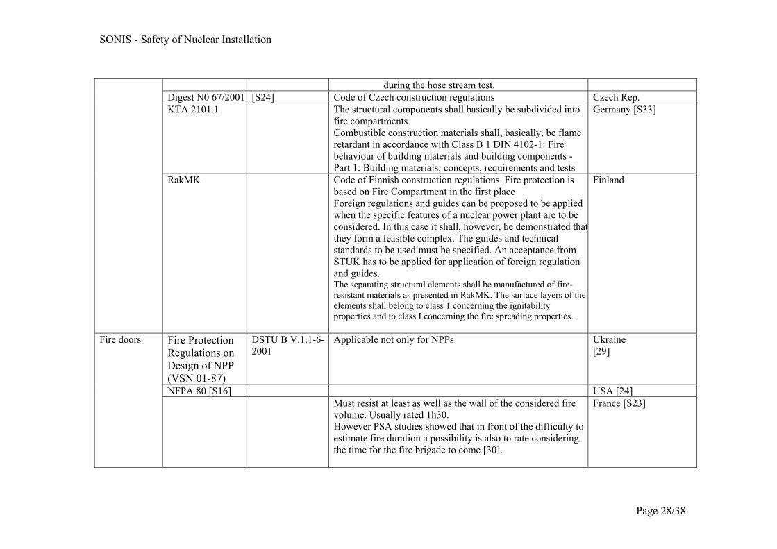
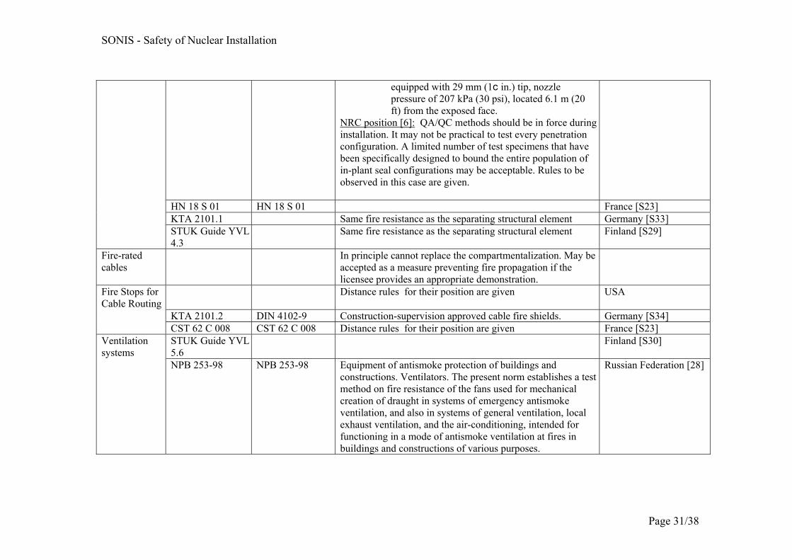
Previous chapters focused on norms and testing procedures for electrical cables and electrical cabinets. Another essential aspect for fire progression and propagation and its capacity to become a large fire is related to the compartment tightness. This report did not consider any experiments and test procedures for components ensuring the compartment tightness. However the corresponding norms requirements and (sometime) description are listed in the following Table 3. The same is done in Table 4 for electrical components. The references given in these tables and beginning with "S" are in the list "references on Standards".
The build up of this table is an on-going action and it will be completed and adapted throughout the project progress.
6 Conclusion and recommendations for future activities
Starting from the point of view of a large fire scenario the response of some fire safety related equipment was examined. Large fire scenarios are often associated to a deliberate action of external origin. Although some aspects of prevention for such fires are very specific (power plant access control, emergency plan, collaboration with the local fire brigade), the fire load on the

SONIS - Safety of Nuclear Installation
Page 26/38
components which are designed for limiting the impact of the fire on the nuclear safety is not linked to the origin of the fire. In fact a better knowledge of the component limits is of interest for the PSA studies as well as for facilitating the purchase of new fire resistant equipment for upgrading the fire safety at nuclear power plant.
This study concentrated on the research of developed norms, standards and their associated tests corresponding to cables and electrical cabinets. A lot of fire norms already exist for electrical cables and their insulation. Although there is still a constant experimental effort for improving the fire resistance of cables, European norms have been defined and are widely accepted.
The fire resistance of electrical cabinets is or has been the topic of a limited amount of experimental programs. Up to now no norm has been issued. A great amount of work has been made on the classification of electrical cabinets, on the reproducibility of their behaviour under fire and on identifying the most fire relevant parameters or features. The work already made helps developing better definition of normative tests for each electrical cabinet class as they can be identified at nuclear power plant. The combustibility of the cabinet as well as its internal arrangement and it size can be well defined inside a given class. The normative feature will then be the vents and the locking.
Other fire equipment is very important for preventing the fire propagation, such as all components constituting passive fire barriers. They were not considered in detail in this report however a list of corresponding norms and related tests is provided as they are recommended or adopted by nuclear safety authorities in Europe, USA, The Russian Federation and Ukraine. The corresponding tables will be completed and updated in the frame of the SONIS project.
In the work program 2008 the project will follow the evolution on new design and testing of electrical cables, will launch a discussion with the main key stakeholders in the “fire” community to estimate if the knowledge collected on fire assessment and testing with regard to electrical cabinets is mature enough for entering a phase of determining the corresponding fire safety requirement needs and the associated test programmes. Furthermore this next step will include fire doors or/and fire dampers.

Page 27/38
Table 3: Norms related to propagation prevention Component Standard or
Safety rules Standard for Testing
Description Country6
NPB 114-02 NPB 113-03 NPB 244-97
Fire-prevention protection of nuclear power plants. Norms of designing. Fire safety of nuclear power plants. General requirements. Building materials. Decorative-finishing and facing materials. Materials for flooring. Roofing, waterproofing, and heat-insulating materials. Characteristics of fire hazard
Russian Federation [28]
Fire Protection Regulations on Design of NPP (VSN 01-87)
DSTU B V.1.1-4-98
Applicable not only for NPPs Ukraine [29]
Structural fire barriers (ex. Walls, floors, ceilings, enclosure)
NFPA 221 [S13]
NFPA 251 [S14] ASTM E-119 [S15]
Test Standard: 1. Applies to construction, materials, workmanship as well
as size of the specimens to be tested. 2. Acceptance criteria [6]:
a. The fire barrier design has withstood the fire endurance test without the passage of flame or the ignition of cotton waste on the unexposed side for a period of time equivalent to the fire-resistance rating required of the barrier.
b. The temperature levels recorded on the unexposed side of the fire barrier are analyzed and demonstrate that the maximum temperature does not exceed 121 °C (250 °F) above the ambient atmosphere.
c. The fire barrier remains intact and does not allow projection of water beyond the unexposed surface
USA Ref [24] Fire rating required for the fire barriers is either 1 or 3 hours.
6 The Standard may not be issued by the regulatory body of the country but accepted by it.
SONIS - Safety of Nuclear Installation
Page 28/38
during the hose stream test. Digest N0 67/2001 [S24] Code of Czech construction regulations Czech Rep. KTA 2101.1 The structural components shall basically be subdivided into
fire compartments. Combustible construction materials shall, basically, be flame retardant in accordance with Class B 1 DIN 4102-1: Fire behaviour of building materials and building components - Part 1: Building materials; concepts, requirements and tests
Germany [S33]
RakMK Code of Finnish construction regulations. Fire protection is based on Fire Compartment in the first place Foreign regulations and guides can be proposed to be applied when the specific features of a nuclear power plant are to be considered. In this case it shall, however, be demonstrated thatthey form a feasible complex. The guides and technical standards to be used must be specified. An acceptance from STUK has to be applied for application of foreign regulation and guides. The separating structural elements shall be manufactured of fire-resistant materials as presented in RakMK. The surface layers of the elements shall belong to class 1 concerning the ignitability properties and to class I concerning the fire spreading properties.
Finland
Fire Protection Regulations on Design of NPP (VSN 01-87)
DSTU B V.1.1-6-2001
Applicable not only for NPPs Ukraine [29]
NFPA 80 [S16] USA [24]
Fire doors
Must resist at least as well as the wall of the considered fire volume. Usually rated 1h30. However PSA studies showed that in front of the difficulty to estimate fire duration a possibility is also to rate considering the time for the fire brigade to come [30].
France [S23]

SONIS - Safety of Nuclear Installation
Page 29/38
KTA 2101.2 DIN 18 095-1 Smoke control doors; Concepts and requirements Germany [S34] STUK Guide YVL 4.3
EI 60 / EI 120 Fire compartmentation used in protecting redundant safety-related systems and separating them from each other shall, in general, have a fire resistance of EI-M 120
Finland [S29]
Fire Protection Regulations on Design of NPP (VSN 01-87)
Ukraine [29]
NFPA 90A [S17] UL 555 [S18] Component Standard: Ventilation fire dampers should be installed within the fire wall penetration for barriers with a fire rating greater than or equal to 2 hours. Test Standard: Does not evaluate whether or not fire dampers will close under airflow conditions. NRC position: "Fire damper surveillance testing should model airflow to ensure that the dampers will close fully when called upon to do so"
USA [24]
KTA 2101.1 Their fire resistance capability shall correspond to that of the partitioning structural elements.
Germany [S33]
Fire dampers
Component Standard: Ventilation fire dampers need to have at least the same fire rating as the wall on which they are installed. Shut automatically (fuse) at 70 °C.
France [S23]
NPB 237-97 NPB 237-97 Building constructions. Fire test methods of cable penetrationsand sealed cable inputs (with alteration №1)
Russian Federation [28] Penetration seals
Fire Protection Regulations on Design of NPP
DSTU B V.1.1-8-2003
Applicable not only for NPPs Ukraine [29]

SONIS - Safety of Nuclear Installation
Page 30/38
(VSN 01-87) NFPA 251 [S14]
ASTM E-119 [S15] ASTM E-814 [S19] IEEE ST. 634 [S20]
Test Standard: 1. Applies to construction, materials, workmanship as well
as size of the specimens to be tested 2. Acceptance criteria [6]:
a. The fire barrier design has withstood the fire endurance test without passage of flame or the ignition of cables on the unexposed side for a period of time equivalent to the fire-resistance rating required of the barrier.
b. The temperature levels recorded for the unexposed side of the fire barrier are analyzed and demonstrate that the maximum temperature does not exceed 163 °C (325 °F) or 121 °C (250 °F) above the ambient temperature. Higher temperatures at through-penetrations may be permitted when justified in terms of cable insulation ignitability.
c. The fire barrier remains intact and does not allow projection of water beyond the unexposed surface during the hose stream test. The stream should be delivered through a 38-mm (1.5-in.) nozzle set at a discharge angle of 30 percent with a nozzle pressure of 517 kPa (75 psi) and a minimum discharge of 284 L/m (75 gpm) with the tip of the nozzle a maximum of 1.5 m (5 ft) from the exposed face, or (2) through a 38-mm (1.5-in.) nozzle set at a discharge angle of 15 percent with a nozzle pressure of 517 kPa (75 psi) and a minimum discharge of 284 L/m (75 gpm) with the tip of the nozzle a maximum of 3 m (10 ft) from the exposed face, or (3) through a 64-mm (2.5-in.) national standard playpipe
USA
SONIS - Safety of Nuclear Installation
Page 31/38
equipped with 29 mm (1c in.) tip, nozzle pressure of 207 kPa (30 psi), located 6.1 m (20 ft) from the exposed face.
NRC position [6]: QA/QC methods should be in force during installation. It may not be practical to test every penetration configuration. A limited number of test specimens that have been specifically designed to bound the entire population of in-plant seal configurations may be acceptable. Rules to be observed in this case are given.
HN 18 S 01 HN 18 S 01 France [S23] KTA 2101.1 Same fire resistance as the separating structural element Germany [S33] STUK Guide YVL 4.3
Same fire resistance as the separating structural element Finland [S29]
Fire-rated cables
In principle cannot replace the compartmentalization. May be accepted as a measure preventing fire propagation if the licensee provides an appropriate demonstration.
Distance rules for their position are given
USA
KTA 2101.2 DIN 4102-9 Construction-supervision approved cable fire shields. Germany [S34]
Fire Stops for Cable Routing
CST 62 C 008 CST 62 C 008 Distance rules for their position are given France [S23] STUK Guide YVL 5.6
Finland [S30] Ventilation systems
NPB 253-98 NPB 253-98 Equipment of antismoke protection of buildings and constructions. Ventilators. The present norm establishes a test method on fire resistance of the fans used for mechanical creation of draught in systems of emergency antismoke ventilation, and also in systems of general ventilation, local exhaust ventilation, and the air-conditioning, intended for functioning in a mode of antismoke ventilation at fires in buildings and constructions of various purposes.
Russian Federation [28]

Page 32/38
Table 4: Related to electrical components fire protection Component Standard Standard for
Testing Description Country
NPB 248-97 NPB 238-97 GOST 12176-89
NPB 248-97 NPB 238-97 GOST 12176-89
Electrical cables and wires. General requirements of fire safety. Test methods (with alteration №1). The present norms apply to cables and wires with a voltage up to 35 KV, intended for a lining in cable constructions and premises. Flame retardant cable coatings. General technical requirements and test methods (with alteration №1). Cables, wires, and cords. Test methods of combustion non-spreading
Russian Federation [28], [S35]
Fire Protection Regulations on Design of NPP (VSN 01-87)
GOST 12176-89, DSTU B V.1.1-11-2005
Cables, conductors and cords. Check methods for flame propagation. Applicable not only for NPPs.
Ukraine [29], [S35]
IEEE St. 383 (old) [S21] IEEE St. 1202 (new) [S22]
NRC position: For (older) cable installations that do not meet the standards, (approved) flame-retardant coating is compulsory. New reactor fibre optic cable insulation and jacketing should also meet the fire and flame test requirements of IEEE 1202. Cables important to safety trays should be designed to allow wetting down with fire suppression water without electrical faulting.
USA Ref [24]
NF C 32-070 NF C 32-070 test No 2.
In case of redundant cable ways, if they have to fit in same cabinet or desk one of the way has to be protected either by a fire rated envelope or a fire resistant painting. Rule for cable installation in envelopes.
France [S23]
Cable Design
DIN VDE 0250-214, DIN VDE 0266, DIN VDE
Cables with improved behaviour in the event of fire. Additional measure can comprise the use of coatings or of special cables.
Germany [S32]

SONIS - Safety of Nuclear Installation
Page 33/38
0282-9 and DIN VDE 0815/A1
Cable function preservation
DIN 4102-12 Functional Capabilities of fire protection equipment cables Germany [S32]
NRC position: High-voltage cabinets (i.e ≥ 480 V) should be provided with adequate spatial separation or substantial physical barriers to minimize the potential for an energetic electrical fault to damage adjacent equipment, cables, or cabinets important to safety. Electrical cabinets containing a quantity of combustible materials (e.g., cabling) sufficient to propagate a fire outside the cabinet of fire origin should be provided with in-cabinet automatic fire detection.
USA Electrical Cabinets
KTA 2101.3 Switch gear and the instrumentation and control equipment shall be housed in metal cabinets.
Germany [S32]

SONIS - Safety of Nuclear Installation
Page 34/38
REFERENCES
1. P. Contri, C. Bruynooghe: "Component Qualification Procedures in Relation to Large Fire Scenarios in Nuclear Installations", in Conference SMIRT 19th, 10th Post Conference Seminar on "Fire Safety in Nuclear Power Plants and Installations", Toronto, August 2007.
2. OECD/NEA/CSNI: "Fire Risk Analysis, Fire Simulation, Fire Spreading and Impact of Smoke and Heat on Instrumentation Electronics". NEA/CSNI/R(99)27
3. IAEA: "Preparation of Fire Hazard Analyses for Nuclear Power Plants", Safety Report Series N° 8.
4. IAEA: "Treatment of Internal Fires in Probabilistic Safety Assessment for Nuclear Power Plants". Safety Report Series N° 10
5. M. Santavy, M. Boleman: "Modernisation of JE-V2 Bohunice fire safety section", Nuclear Engineering International's fifth Fire & Safety conference, Munich 11-12 March 2004
6. Building Research Establishment: http://projects.bre.co.uk/frsdiv/designfires/background.htm
7. W. Neugebauer: "EPR Fire Protection Concept. Passive Fire Protection as part of the Safety Approach". in Conference SMIRT 19th, 10th Post Conference Seminar on "Fire Safety in Nuclear Power Plants and Installations", Toronto August 2007
8. V. Babrauskas, R.D. Peacock, E. Braun, R.W. Bukowski, W.C. Jones: "Fire performance of Wire and Cable: Reaction to Fire Tests – A Critical Review of the Existing Methods and of New Concepts". NIST Technical Note 1291, Dec. 1991
9. Fire Performance of Electric Cables – new test methods and measurement techniques, FIPEC Consortium 1999.
10. J. Marttila : "Assessing the Fire Safety of FRNC Cables for Olkiluoto 3 EPR in Finland", , in Conference SMIRT 19th, 10th Post Conference Seminar on "Fire Safety in Nuclear Power Plants and Installations", Toronto, August 2007.
11. O. Riese, D. Hosser : "Fire Behavior of Cables With Insulation Materials Frequently Use in Nuclear Power Plants", in Conference SMIRT 19th, 10th Post Conference Seminar on "Fire Safety in Nuclear Power Plants and Installations", Toronto, August 2007.
12. O M. H. Salley, S. P. Nowlen, K. McGrattan: "CAROLFIRE - Cable Response to Live Fire, in Conference SMIRT 19th, 10th Post Conference Seminar on "Fire Safety in Nuclear Power Plants and Installations", Toronto, August 2007.
13. E. Avidor, F.J. Joglar-Billoch, F.W.Mowrer, M. Modarres: "Hazard assessment of fire in Electrical Cabinets". Nuclear Technology, Vol. 144, Dec. 2003

SONIS - Safety of Nuclear Installation
Page 35/38
14. J.M. Chavez, “An Experimental Investigation of Internally Ignited Fires in Nuclear Power Plant Control Cabinets: Part I, Cabinet Effects Tests,” NUREG/CR-4527, Volume 2, U.S. Nuclear Regulatory Commission, Washington, DC, April 1987.
15. J. Mangs, J. Paananen, O. Keski-Rahkonen: "Calorimetric fire experiments on electronic cabinets". Fire Safety Journal 38 (2003) 165-186.
16. J. Mangs, O. Keski-Rahkonen: "Full Scale Fire Experiments on Electronic Cabinets II". 1996, VTT publication 269
17. S. Mélis, L. Rigollet, J.M. Such, C. Casselman: "Modelling of Electrical Cabinet Fires based on the CARMELA Experimental Program". Eurosafe 2004, Berlin 8-9-Nov 2004
18. M. Faury, P. Guillou, W. Le Saux, H. Prétrel, M. Coutin: "Large Scale Fire Experiments in Confined and Mechanically ventilated Compartments: the OECD PRISME Fire Research Project and the PICSEL Program", in Conference SMIRT 19th, 10th Post Conference Seminar on "Fire Safety in Nuclear Power Plants and Installations", Toronto August 2007.
19. Simo Hostikka, Olavi Keski-Rahkonen: "Probabilistic simulation of fire scenarios". Nuclear Engineering and Design, 224 (2003) 301-311.
20. O. Keski-Rahkonen, J. Björkman: "Critical Heating Time of Equipment Exposed to Fire Temperatures". Transaction SMIRT 16, Washington DC, August 2001.
21. Steven P. Nowlen: "A review of Research at Sandia National Laboratories Associated with the problem of Smoke Corrosivity". Fire Safety Journal 15 (1989), 403-413.
22. J. Mangs, O. Keski-Rahkonen: "Acute Effects of Smoke on Performance of Control Electronic in NPPs". Transaction SMIRT 16, Washington DC, August 2001.
23. T.J. Tanaka, S.P. NOwlen, K. Korsah, R.T Wood, C.E. Antonescu: "Impact of smoke exposure on Digital Instrumentation and Control". Nuclear Technology, vol. 143, Aug. 2003.
24. USNRC: "Fire protection for nuclear power plants. NRC Regulatory Guide 1.189" Rev. March 2007. http://www.nrc.gov/reading-rm/doc-collections/reg-guides/power-reactors/active/.
25. Materials for “Best-Practice” Safety Cabling Solutions, David B. Kiddoo, International Wire and Cable Symposium, November 2004.
26. IEC Technical Report 62222 - Fire performance of communication cables in buildings.
27. P. Lamuth, F. Arnould: "A Conservative Theory of Full-Development fire in an Electrical Cabinet" in Conference SMIRT 19th, 10th Post Conference Seminar on "Fire Safety in Nuclear Power Plants and Installations", Toronto August 2007.
28. A. Lelyukhin: "Normative Documents on Fire Safety at Russian NPPs". Private Communication. Nov. 2007.
29. S. Gazin, "Ukrainian fire standards", Private Communication, Nov. 2007.

SONIS - Safety of Nuclear Installation
Page 36/38
30. Ph. Dupuy, O. Gupta: "Les principes de la protection contre l'incendie dans les INB et les actions de l'autorité de sûreté" in "Le risque d'incendie dans les installations nucléaires", journal "Contrôle" from Autorité de Sûreté Nucléaire, n° 136, September 2000.
31. Materials for “Best-Practice” Safety Cabling Solutions, David B. Kiddoo, International Wire and Cable Symposium, November 2004
32. Electric Cables Handbook, George F. Moore, 1997, Blackwell Publishing, ISBN 0632040750
REFERENCES STANDARDS FOR CABLES AND FOR OTHER NPP COMPONENTS
S1 IEC 60331-11: Tests for electric cables under fire conditions – Circuit
integrity – Part 11: Apparatus – Fire alone at a flame temperature, of at least 750 °C
S2 IEC 60331-12: Tests for electric cables under fire conditions – Circuit
integrity – Part 12: Apparatus – Fire with shock at a temperature of at least 830 °C
S3 IEC 60331-31: Tests for electric cables under fire conditions – Circuit
integrity – Part 31: Procedures and requirements for fire with shock – Cables of rated voltage up to and including 0,6/1 kV
S4 IEC 60332-1: Tests on electric and optical fibre cables under fire
conditions – Part 1: Test for vertical flame propagation for a single insulated wire or cable.
S5 IEC 60332-2: Tests on electric and optical fibre cables under fire
conditions – Part 2: Test for vertical flame propagation for a single small insulated wire or cable.
S6 IEC 60332-3: Tests on electric and optical fibre cables under fire
conditions – Part 3: Part 3-10: Test for vertical flame spread of vertically-mounted bunched wires or cables.
S7 IEC 60754-1: Test on gases evolved during combustion of materials from
cables -Part 1: Determination of the amount of halogen acid gas. S8 IEC 60754-2: Test on gases evolved during combustion of materials from
cables Part 2: Determination of degree of acidity of gases evolved during the combustion of materials taken from electric cables by measuring pH and conductivity
S9 IEC 61034-1: Measurement of smoke density of cables burning under
defined conditions – Part 1: Test apparatus

SONIS - Safety of Nuclear Installation
Page 37/38
S10 IEC 61034-2: Measurement of smoke density of cables burning under
defined conditions – Part 2: Test procedure and requirements S11 UL 1685 - UL Standard for Safety Vertical-Tray Fire-Propagation and
Smoke-Release Test for Electrical and Optical-Fiber Cables, Underwriters Laboratories Inc., Apr 25, 2007
S12 ICEA T-30-520: ICEA Standard for Vertical Tray Flame Tests at 70,000
Btu. S13. NFPA 221, “Standard for High-Challenge Fire Walls, Fire Wall and
Barrier Walls” National Fire Protection Association, Quincy", MA.
S14. NFPA 251, “Standard Methods of Tests of Fire Endurance of Building Construction and Materials,” National Fire Protection Association, Quincy, MA.
S15. Annual Book of ASTM Standards, ASTM E-119, “Standard Test Methods for Fire Tests of Building Construction and Materials", Annual Book of ASTM Standards, American Society for Testing and Materials, PA.
S16. NFPA 80, “Standard for Fire Doors and other opening protectives” National Fire Protection Association, Quincy, MA.
S17. NFPA 90A, “NFPA 90A, “Standard for the Installation of Air-Conditioning and Ventilating Systems," National Fire Protection Association, Quincy, MA.
S18. UL 555, “Fire Dampers,” Underwriters Laboratories, Inc., Northbrook, Illinois (see http://www.ul.com/info/standard.htm).
S19. ASTM E-814, “Standard Test Method for Fire Tests of Through-Penetration Fire Stops, ”Annual Book of ASTM Standards, American Society for Testing and Materials, West Conshohocken, PA.25
S20. IEEE 634, “IEEE Standard Cable Penetration Fire Stop Qualification Test” Institute of Electrical and Electronics Engineers, Piscataway, NJ.
S21. IEEE 383, “IEEE Standard for Type Test of Class IE Electric Cables, Field Splices, and Connections for Nuclear Power Generating Stations,” Institute of Electrical and Electronics Engineers, Piscataway, NJ.22
S22. IEEE 1202, “IEEE Standard for Flame Testing of Cables for Use in Cable Trays in Industrial and Commercial Occupancies,” Institute of Electrical and Electronics Engineers, Piscataway, NJ.22
S23. Règles de Conception et de Construction des Centrales Nucléaires REP. Règles applicables à la protection Incendie: RCC-I. ASN
S24. Arrêté from 21 April 1983
S25. Czech Regulation V195 § 9.
S26. http://www.stuk.fi/julkaisut_maaraykset/viranomaisohjeet/en_GB/yvl/Ghh control the link it is for STUK

SONIS - Safety of Nuclear Installation
Page 38/38
S27. NFPA 92B Guide for smoke management systems in malls, atria and large areas, National Fire Protection Association, Quincy, Massachusetts, USA, 1995.
S28. ISO 5659-2:1994. Plastics – Smoke generation – Part 2: Determination of optical density by a single-chamber test. Geneva: International Organisation for Standardisation, 1994.
S29. STUK Guide YVL 4.3: Fire Protection at Nuclear facilities
S30. STUK Guide YVL 5.6: Air-conditioning and ventilation systems and components of nuclear facilities.
S31. STUK Guide YVL 1.0: Safety criteria for design of nuclear power plants.
S32. KTA2101.3 (12/2000): Safety Standards of the Nuclear Safety Standards Commission (KTA). Fire Protection in Nuclear Power Plants. Part 3: Fire Protection of Mechanical and Electrical Plant Components.
S33. KTA2101.1 (12/2000): Safety Standards of the Nuclear Safety Standards Commission (KTA). Fire Protection in Nuclear Power Plants. Part 1: Basic Requirements
S34. KTA2101.2 (12/2000): Safety Standards of the Nuclear Safety Standards Commission (KTA). Fire Protection in Nuclear Power Plants. Part 2: Fire Protection of Structural Plant Components.
S35. GOST 12176-89 (ST SEV 2781-80, ST SEV 6456-88). Cables, conductors and cords. Check methods for flame propagation.

European Commission EUR 23231 EN – Joint Research Centre – Institute for Energy Title: F i r e p r o t e c t i o n i n N P P : c h a l l e n g e s p o s e d t o t h e e q u i p m e n t a n d s t a t u so f t h e i r q u a l i f i c a t i o n Auth o r s : C . B R U Y N O O G H E , A . B U C A L O S S I , P . C O N T R I Luxembourg: Office for Official Publications of the European Communities 2008 – 43 pp. – 21 x 29.7 cm EUR – Scientific and Technical Research series – ISSN 1018-5593 Abstract This Report summarizes the results of the studies performed by the JRC/IE in 2007 on Task 2 of the SONISresearch program which is devoted to the Safety of Nuclear Installations. The aim of this task is to identify the firerelated parameters associated to the design basis scenarios for accidental and malevolent events, and to identifythe Systems, Structures and Components where the vulnerabilities are important for the overall safety evaluationof the plants. This report collects information on standard qualification tests and on experimental fire resistance tests for cablesand electrical cabinets. This report prepares the next step of the SONIS program which will consist in estimating (together with the mainkey players in the "fire" community from Europe, the OECD countries, The Russian Federation and the Ukraine):- to which extent national norms are consistent nd covering all safety aspects- if certain experimental programs are mature enough to allow qualification test definition for those component which still have none.This work will be followed in 2008.

How to obtain EU publications Our priced publications are available from EU Bookshop (http://bookshop.europa.eu), where you can place an order with the sales agent of your choice. The Publications Office has a worldwide network of sales agents. You can obtain their contact details by sending a fax to (352) 29 29-42758.

The mission of the JRC is to provide customer-driven scientific and technical support for the conception, development, implementation and monitoring of EU policies. As a service of the European Commission, the JRC functions as a reference centre of science and technology for the Union. Close to the policy-making process, it serves the common interest of the Member States, while being independent of special interests, whether private or national.