Embed Size (px)
Citation preview
Fire Performance Cables
asean.prysmiangroup.com
Prysmian Group
facebook.com/prysmian.asean

World leader in energy and telecom cables & systems
Prysmian Group in ASEAN
With nearly 140 years of experience, sales of over €11 billion in 2017, 30,000 employees across 50 countries and 112 plants, the Prysmian Group is strongly positioned in high- tech markets and offers the widest possible range of products, services, technologies and know-how.
Through three renowned commercial brands - Prysmian, Draka and General Cable – which are distributed globally, we’re constantly close to our customers, enabling them to further develop the world’s energy and telecoms infrastructures, and achieve sustainable, profitable growth.
Prysmian Group ASEAN operates with 7 plants in Malaysia, Indonesia, Philippines and Thailand, as well as a regional distribution centre in Singapore that serves the Energy, Infrastructure and Telecom markets in the region.
From creating a new system to address complex cable-fitting of the Marina Bay Sands, to providing European expertise on unprecedented submarine cable projects in South Vietnam, a rigorous culture of innovation is core to the Prysmian business.
With a robust physical presence and our innovative edge, the group is poised to take on the rapidly growing ASEAN market.
OUR CORPORATE BRAND
01
OUR COMMERCIAL BRANDS
One name that represents our global presence and what we stand for.
Strong, reliable and familiar. Prysmian, Draka & General Cable products resonate greatly within the industry and has been doing so for decades.
Petronas Twin Towers, Kuala Lumpur
Marina Bay Sands, Singapore
Hanoi Museum, Hanoi
Suvarnabhumi International Airport,
Bangkok

Our Strengths and Businesses
02
UTILITIES
INDUSTRIAL
TRADE & INSTALLERS
TELECOM
• Power Transmission
• Specialities & OEM
• LV cables for construction
• Telecom solutions
• Network Components
• Power Distribution
• Automotive• OGP & SURF• Renewables• Elevator• Other industrial (aviation, branchment, other)
• Multimedia solutions
• Optical Fibre
- Underground EHV, HV-DC/AC- Submarine (turn-key) EHV - DC/AC(extruded, mass impregnated and SCFF) and MV
- (rolling stock, nuclear, defence, crane, mining, marine, electro medical, railway, other infrastructure)
- Fire Performance- Environment-Friendly standards- Low Smoke Halogen Free (LSHF)- Application-specific products
- Optical fibre- Connectivity- OPGW- Copper cable
- Datacoms & Structure Cablings Solutions- Multimedia specials- Mobile networks - Signalling
- Joints, connectors and terminations from LV to EHV
- LV, MV (P-Laser)
Contents2018 Edition
Fire Performance Cables by Prysmian Group
03

05Prysmian Fire Performance• Fire Demands Performance• Prysmian Means Performance• Applications
Technical & Standards• Construction of Cable• Standards and Approvals• Flame Propagation Tests• Corrosive & Acid Gas Emission Test• Smoke Emission Tests
07
Our Products• FireTUF Classic MI SIFER (i)• FireTUF Classic MI SIFER (s)• FireTUF Classic MI POWER Unarmoured• FireTUF Classic MI POWER Armoured• MAX-FOH-I• MAX-FOH• MAX-FOH 125• MAX-FOH-AWA• MAX-FOH-SWA
11
AppendicesA. Introduction to Cable Materials
B. Selection of Cross-Sectional Area of Conductor
C. Current Ratings and Voltage Drop Table (Unarmoured Cables)
D. Current Ratings and Voltage Drop Table (Armoured Cables)
E. Short Circuit Ratings
F. Cables & Drum Handling and Storage Procedure
G. Identification of Cable Cores
25
04

Fire Demands Performance
Prysmian Means Performance
In any infrastructure, safety features designed to mitigate loss of human life and damage to property are not just required by regulations worldwide, but represent the gold standard in construction. One of these staple features supplied by Prysmian are Fire Performance cables, which connect critical building systems such as fire alarms, emergency lighting, PA & CCTV systems, emergency power supplies and smoke & fire shutters.
Fire Performance cables are crucial in an emergency situation, ensuring that under mechanical stress and high heat, these systems will continue to operate to effectively conduct an orderly evacuation of the premise and aid emergency services in gaining quick & effective entry to deal with the hazard.
Prysmian Group has been manufacturing the widest range of industry-leading Fire Performance cables, known as MAX FOH™ in ASEAN, for over twenty years.
6 advantages of buying MAX-FOH over OEM & substitutes:
1. Original manufacturer certification eliminates OEM-related problems like consistency and warranty.
2. Full-sized conductors, insulation and sheathing are used; that means no cutting corners with cheaper undersized ones.
3. Multi-layered Mica fire barrier tape meets industry standards, exceeds those of competitor makes.
4. Insulated by Low Smoke Halogen Free (LSHF) material, an industry standard for flame retardant cables.
5. Only the best flame and smoke suppressants are used. Cheap polymers save cost, but are not worth the safety risk.
6. All MAX-FOH products undergo recognised 3rd party standards and approvals, meeting various International Electrotechnical Commission and British Standards.
05
Prysmian & Draka Cables, Flame Propagation Test
Generic Cables
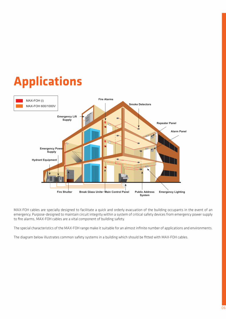
Applications
MAX-FOH cables are specially designed to facilitate a quick and orderly evacuation of the building occupants in the event of an emergency. Purpose-designed to maintain circuit integrity within a system of critical safety devices from emergency power supply to fire alarms, MAX-FOH cables are a vital component of building safety.
The special characteristics of the MAX-FOH range make it suitable for an almost infinite number of applications and environments.
The diagram below illustrates common safety systems in a building which should be fitted with MAX-FOH cables.
06
Fire Alarms
Smoke Detectors
Repeater Panel
Alarm Panel
Emergency Lift Supply
Emergency Power Supply
Hydrant Equipment
Fire Shutter Break Glass Units Main Control Panel Public Address System
Emergency Lighting
MAX-FOH (i)
MAX-FOH 600/1000V

07
Construction of Cable
Core Identification
SINGLE CORE, UNARMOURED SINGLE CORE, ARMOURED
MULTI-CORE, UNARMOURED MULTI-CORE, ARMOURED
1
2
3
8
# 1 2 3 4*
*optional to cable construction
These are standard configurations. Customisations to any component is available upon request.
5* 6* 7* 8*
Construction
Core Numbers
Material
Colourconfigurations
Conductor
1
StrandedAnnealed
Copper
White
or or or or
MicaTape
LowSmoke
Halogen-Free (LSHF) /
CrosslinkedPolyethylene
(XLPE)compound
LSHFor
PolypropyleneSplit Yarn
Polyester LSHFcompound
Black withwhite numbers
Galvanised Steel or
Aluminium Wire (Braiding
Optional)
LSHFcompound
Fire Barrier
2
Insulation
3
Filler
4
Binder Tape
5
Bedding
6 and above
Armour Sheath
1 12345678
23
4
5
6
123678

Standard
IEC 60331
SS299 : Part 1
BS 6387 : 2013
60331-21
Category C
60331-1
Category W
Category Z
Protocol C
Protocol W
Protocol Z
750°C
950°C
Fire
Fire
850°C
650°C
950°C
Fire
Fire & Water
Fire withMechanical Shock
950°CFire
650°C
950°C
Fire & Water
Fire withMechanical Shock
At least 90 mins
For 3 hours
At least 120 mins
Fire for 15 minutesFire and waterfor 15 minutes
For 15 minutes,with 30 secondhammer blows
For 3 hours
Fire for 15 minutesFire and waterfor 15 minutes
For 15 minutes, with 30 second hammer blows
Part / Category TemperatureResistance to Time
Standards and ApprovalsDraka cables are certified by multiple internationally recognised cable standards. Here are the listed IEC, SS and BS standards categorised by type of fire test.
These tests are used to determine if a cable is capable of maintaining circuit integrity under:
Fire Fire with water Fire with mechanical shock
These tests use a number of alternative time and temperature parameters and depending on the level achieved by the cable, a corresponding letter is assigned to denote the category that the cable passes.
Fire Resistance Tests
08

Flame Propagation TestsThis test defines the ability of bunched cables to restrict vertical flame propagation when laid in trunking, cable trays or conduit. The test comprises of 4 categories each determined by the amount of combustible material in a 1 metre sample.
The cable samples are placed vertically next to one another on a vertical ladder where they are exposed to fire from a ribbon gas burner for the pre-arranged times.
After burning, the samples are cleaned to examine for char (the crumbling) on the cable surface. The charring should not have reached a height exceeding 2.5m above the bottom edge of the burner.
Standard
IEC
BS
Single
Bunched
Bunched
Bunched
Bunched
Single
Bunched
Bunched
Bunched
Bunched
Single / Bunched
60332-1-2
60332-3-22Category A
EN 60332-3-22Category A
EN 60332-3-23Category B
EN 60332-3-24Category C
EN 60332-3-25Category D
60332-3-22Category B
60332-3-24Category C
60332-3-25Category D
EN 60332-1-2
Standard & Category
-
7.0
7.0
3.5
1.5
0.5
3.5
1.5
0.5
-
Amount of Combustible Material in 1 metre
Sample in Litres
-
40
40
40
20
20
40
20
20
-
Time of Exposure in Minutes
09
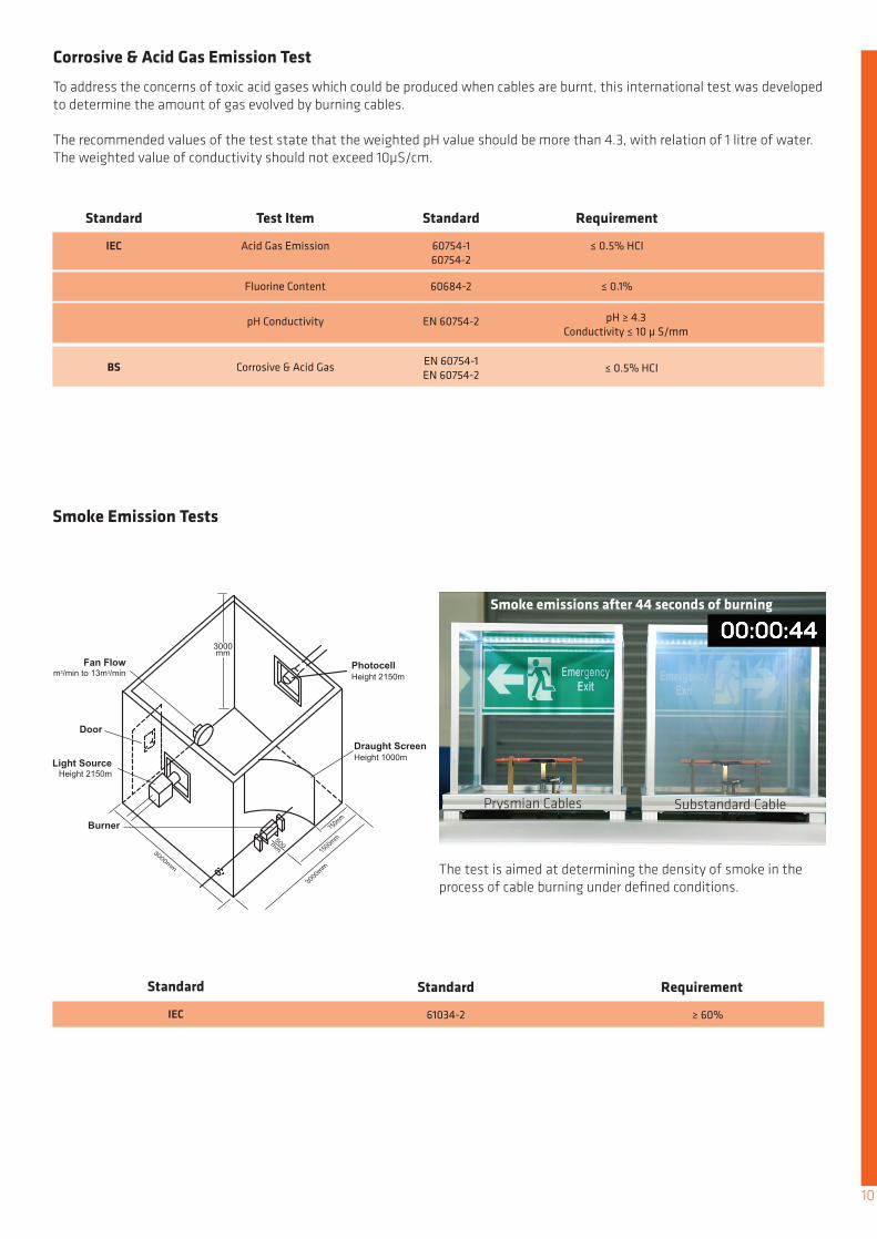
Corrosive & Acid Gas Emission Test
Smoke Emission Tests
To address the concerns of toxic acid gases which could be produced when cables are burnt, this international test was developed to determine the amount of gas evolved by burning cables.
The recommended values of the test state that the weighted pH value should be more than 4.3, with relation of 1 litre of water. The weighted value of conductivity should not exceed 10µS/cm.
The test is aimed at determining the density of smoke in the process of cable burning under defined conditions.
Standard
Standard
IEC
IEC
BS
Acid Gas Emission
61034-2
Fluorine Content
pH Conductivity
Corrosive & Acid Gas
60754-160754-2
≥ 60%
60684-2
EN 60754-2
EN 60754-1EN 60754-2
≤ 0.5% HCI
≤ 0.1%
pH ≥ 4.3Conductivity ≤ 10 μ S/mm
≤ 0.5% HCI
Test Item
Standard
Standard Requirement
Requirement
10
Prysmian Cables Substandard Cable
Smoke emissions after 44 seconds of burning

Application & Features Thermal Characteristics
Bending Radius Performance Characteristics
Identification
Conductor
Fire BarrierInsulation
These cables are designed for drawing into trucking and conduit in installation where a fire situation may pose a major hazard and the maintenance of circuit integrity is a requirement. To achieve optimum performance they should be installed in metal conduit.
Circuit Integrity:
IEC 60331BS 6387, C, W & Z
Reference Standard:
IEC 60228BS 6360 (Class 2)
Flame Retardant:
IEC 60332-1, 60332-3, A, B, C
Acid Gas Emission:
IEC 60754
Smoke Emission:
IEC 61034
Minimum bending radius
8 x overall diameter
UV Resistance
Anti- RodentAnti- Termite Other Sheath colours are available
Insulated, non-sheathed
• Stranded Plain Annealed• Class 2• Circular or compact
Mica Glass TapeXLEVA Compound (OHLS)
Optional Features
Operating Temperature
-40°C to 110°C
11
0.6 / 1kV
Insulation colour
Cable Size
mm2
1x1.51x2.51x41x61x101x161x251x351x501x701x951x1201x1501x1851x2401x3001x4001x5001x630
mm0.70.80.80.81.01.01.21.21.41.41.61.61.82.02.22.42.62.82.8
mm3.84.45.05.56.87.89.6
10.812.614.316.618.120.222.425.328.431.735.339.1
kg/km ohm/km28 12.1041 7.4157 4.6178 3.0812018028037050069095011001400180023002900370047006000
1.831.15
0.7270.5240.3870.2680.1930.1530.124
0.09910.07540.06010.047
0.03660.0283
Insulation Thickness
Cable OverallDiameter
Cable Weight
Max Conductor Resistance at 20oC

Application & Features Thermal Characteristics
Bending Radius Performance Characteristics
Identification
Conductor
Fire BarrierInsulationSheath
These cables are designed for surface wiring where there is little risk of mechanical damage, in installations where a fire situation may pose a major hazard and the maintenance of circuit integrity is a requirement. They are also suitable for installation in metal conduit or trunking where conditions are onerous.
Circuit Integrity:
IEC 60331BS 6387, C, W & Z
Reference Standard:
IEC 60228BS 6360 (Class 2)
Flame Retardant:
IEC 60332-1, 60332-3, A, B, C
Acid Gas Emission:
IEC 60754
Smoke Emission:
IEC 61034
Minimum bending radius
8 x overall diameter
UV Resistance
Anti- RodentAnti- Termite Other Sheath colours are available
Insulated, sheathed0.6 / 1kV
• Stranded Plain Annealed• Class 2• Circular or compact
Mica Glass TapeXLEVA Compound (OHLS)LSHF Compound
Optional Features
Operating Temperature
-40°C to 110°C
Outer Sheath
Core ColourInsulation
12
Cable Size
mm2
1x1.51x2.51x41x61x101x161x251x351x501x701x951x1201x1501x1851x2401x3001x4001x5001x630
mm0.70.70.70.70.70.70.90.91.01.11.11.21.41.61.71.82.02.22.4
Nominal Insulation Thickness
mm1.41.41.41.41.41.41.41.41.41.41.51.51.61.71.71.81.92.12.2
Nominal Insulation Thickness
mm6.67.17.68.29.210.312.013.214.716.718.820.622.725.228.030.934.438.442.9
Approx. Overall Diameter
MΩ/km0.01000.00900.00700.00650.00650.00500.00500.00400.00450.00350.00350.00320.00320.00320.00320.00300.00280.00280.0025
Insulation Resistance at 90oC
Ω/km12.17.414.613.081.831.15
0.7270.5240.3870.2680.1930.1530.124
0.09910.07540.06010.047
0.03660.0283
Max Conductor Resistance at 20oC
kg/km6679
100125177244357463599825110213641671208126703308419052566710
ApproxWeight
• Stranded Plain Annealed• Class 2• Circular or compact

Application & Features Thermal Characteristics
Bending Radius Performance Characteristics
Identification
Conductor
Fire BarrierInsulationSheath
These cables offer the advantages of an unarmoured 600/1000 Volt rated, zero halogen, low smoke cable with enhanced circuit integrity. They are intended for use in installations where vital circuits are required to continue to operate in the event of an outbreak of fire. They are particularly suited for use in public buildings, such as hospitals, theatres, shopping developments, tunnels, mass transit utilities, oil & petrochemcial plants, power stations and computer installations where the danger to life, equipment and structures may be greatly increased in the event of a power failure due to fire.
Circuit Integrity:
IEC 60331BS 6387, C, W & Z
Reference Standard:
IEC 60228BS 6360 (Class 2)
Flame Retardant:
IEC 60332-1, 60332-3, A, B, C
Acid Gas Emission:
IEC 60754
Smoke Emission:
IEC 61034
Minimum bending radius
8 x overall diameter
UV Resistance
Anti- RodentAnti- Termite Other Sheath colours are available
0.6/1kV, Unarmoured
• Stranded Plain Annealed• Class 2• Circular or compact
Mica Glass TapeXLEVA CompoundLSHF Compound
Optional Features
Operating Temperature
-40°C to 110°C
13
Outer Sheath
Core ColourInsulation
Cable Size
mm2
2x1.52x2.52x42x62x102x162x252x352x502x702x952x1202x1502x1852x2402x3002x400
mm0.70.70.70.70.70.70.90.91.01.11.11.21.41.61.71.82.0
Nominal Insulation Thickness
mm1.81.81.81.81.81.81.81.81.81.82.02.12.22.32.52.62.9
Nominal Sheath
Thickness
Classic Enhanced Max Conductor Resistance
Ω/km15.4289.4485.8783.9282.3351.4690.9300.6730.5000.3490.2580.2090.1760.1480.1220.1070.096
ImpedanceAC at 90oC
Ω/km15.4289.4485.8783.9272.3331.4660.9270.6680.4940.3420.2470.1960.1600.1280.0990.0800.064
AC at 90oC
Ω/km12.17.414.613.081.831.15
0.7270.5240.3870.2680.1930.1530.124
0.09910.07540.06010.047
DC at 20oC
Ω/km0.1040.1010.0990.0940.0930.0880.0820.0770.0760.0750.0740.0720.0730.0730.0720.0720.071
Reactance at 50Hz
mm11.312.113.214.316.518.622.124.527.431.435.639.443.548.354.359.867.1
Approx. Overall Diameter
kg/km1832222793474315898631,1121,4381,9672,6293,2653,9904,9526,3897,87310,011
ApproxWeight
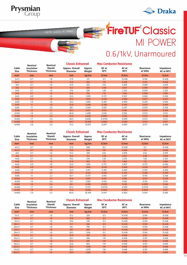
0.6/1kV, Unarmoured
14
Cable Size
mm2
3x1.53x2.53x43x63x103x163x253x353x503x703x953x1203x1503x1853x2403x3003x400
mm0.70.70.70.70.70.70.90.91.01.11.11.21.41.61.71.82.0
Nominal Insulation Thickness
mm1.81.81.81.81.81.81.81.81.81.92.02.12.32.42.62.83.0
Nominal Sheath
Thickness
Classic Enhanced Max Conductor Resistance
Ω/km15.4289.4485.8783.9282.3351.4690.9300.6730.5000.3490.2580.2090.1760.1480.1220.1070.096
ImpedanceAC at 90oC
Ω/km15.4289.4485.8783.9272.3331.4660.9270.6680.4940.3420.2470.1960.1600.1280.0990.0800.064
AC at 90oC
Ω/km12.17.414.613.081.831.15
0.7270.5240.3870.2680.1930.1530.124
0.09910.07540.06010.047
DC at 20oC
Ω/km0.1040.1010.0990.0940.0930.0880.0820.0770.0760.0750.0740.0720.0730.0730.0720.0720.071
Reactance at 50Hz
mm11.912.813.915.217.619.823.526.229.333.838.142.346.852.058.564.572.2
Approx. Overall Diameter
kg/km211260322420534746
1,0991,4301,9402,6983,5944,4715,4986,8388,83010,94913,875
ApproxWeight
Cable Size
mm2
4x1.54x2.54x44x64x104x164x254x354x504x704x954x1204x1504x1854x2404x3004x400
mm0.70.70.70.70.70.70.90.91.01.11.11.21.41.61.71.82.0
Nominal Insulation Thickness
mm1.81.81.81.81.81.81.81.81.82.02.22.32.42.62.83.03.3
Nominal Sheath
Thickness
Classic Enhanced Max Conductor Resistance
Ω/km15.4289.4485.8783.9282.3351.4690.9300.6730.5000.3490.2580.2090.1760.1480.1220.1070.096
ImpedanceAC at 90oC
Ω/km15.4289.4485.8783.9272.3331.4660.9270.6680.4940.3420.2470.1960.1600.1280.0990.0800.064
AC at 90oC
Ω/km12.17.414.613.081.831.15
0.7270.5240.3870.2680.1930.1530.124
0.09910.07540.06010.047
DC at 20oC
Ω/km12.17.414.613.081.831.15
0.7270.5240.3870.2680.1930.1530.124
0.09910.07540.06010.047
Reactance at 50Hz
mm12.913.915.216.619.221.825.928.932.437.742.746.852.158.165.372.080.8
Approx. Overall Diameter
kg/km248309399512678952
1,4191,8452,4113,5264,7275,8377,2008,99611,61714,40218,300
ApproxWeight
Cable Size
mm2
7x1.510x1.512x1.516x1.520x1.521x1.530x1.57x2.5
10x2.512x2.516x2.520x2.521x2.530x2.5
mm0.70.70.70.70.70.70.70.70.70.70.70.70.70.7
Nominal Insulation Thickness
mm1.81.81.81.81.81.81.81.81.81.81.81.81.81.8
Nominal Sheath
Thickness
Classic Enhanced Max Conductor Resistance
Ω/km15.42815.42815.42815.42815.42815.42815.4289.4489.4489.4489.4489.4489.4489.448
ImpedanceAC at 90oC
Ω/km15.42815.42815.42815.42815.42815.42815.4289.4489.4489.4489.4489.4489.4489.448
AC at 90oC
Ω/km12.112.112.112.112.112.112.17.417.417.417.417.417.417.41
DC at 20oC
Ω/km0.1040.1040.1040.1040.1040.1040.1040.1010.1010.1010.1010.1010.1010.101
Reactance at 50Hz
mm15.219.019.621.724.124.128.216.420.721.323.626.326.330.9
Approx. Overall Diameter
kg/km3294605186587968261,128418586674855
1,0381,0781,485
ApproxWeight

Application & Features Thermal Characteristics
Bending Radius Performance Characteristics
Identification
Conductor
Fire BarrierInsulationSheath
These cables offer the advantages of an unarmoured 600/1000 Volt rated, zero halogen, low smoke cable with enhanced circuit integrity. They are intended for use in installations where vital circuits are required to continue to operate in the event of an outbreak of fire. They are particularly suited for use in public buildings, such as hospitals, theatres, shopping developments, tunnels, mass transit utilities, oil & petrochemcial plants, power stations and computer installations where the danger to life, equipment and structures may be greatly increased in the event of a power failure due to fire.
Circuit Integrity:
IEC 60331BS 6387, C, W & Z
Reference Standard:
IEC 60228BS 6360 (Class 2)
Flame Retardant:
IEC 60332-1, 60332-3, A, B, C
Acid Gas Emission:
IEC 60754
Smoke Emission:
IEC 61034
Minimum bending radius
10 x overall diameter
UV Resistance
Anti- RodentAnti- Termite Other Sheath colours are available
0.6/1kV, Armoured
• Stranded Plain Annealed• Class 2• Circular or compact
Mica Glass TapeXLEVA CompoundLSHF Compound
Optional Features
Operating Temperature
-40°C to 110°C
15
Outer Sheath
Core ColourInsulation
Cable Size
mm2
2x1.52x2.52x42x6
2x102x162x252x352x502x702x95
2x1202x1502x1852x2402x300
mm0.70.70.70.70.70.70.90.91.01.11.11.01.41.61.71.8
Nominal Insulation Thickness
mm1.01.01.01.01.01.01.01.01.01.01.21.21.21.41.41.6
Nominal Bedding
Thickness
mm1.81.81.81.81.81.81.81.81.92.02.12.22.42.52.72.9
Nominal Sheath
Thickness
mm11.512.313.414.517.419.523.726.129.033.038.041.645.551.557.162.8
Nominal Dia. under
Armour
mm15.115.917.018.121.023.127.329.732.837.042.246.050.356.562.568.6
Approx. Overall
Diameter
Ω/km15.4289.4485.8783.9282.3351.4690.9300.6730.5000.3490.2580.2090.1760.1480.1220.107
ImpedanceAC at 90oC
Max ConductorResistance
Ω/km15.4289.4485.8783.9272.3331.4660.9270.6680.4940.3420.2470.1960.1600.1280.0990.080
AC at 90oC
Ω/km12.17.414.613.081.831.15
0.7270.5240.3870.2680.1930.1530.124
0.09910.07540.0601
DC at 20oC
Ω/km0.1040.1010.0990.0940.0930.0880.0820.0770.0760.0750.0740.0720.0730.0730.0720.072
Reactance at
50Hz
mm0.90.90.90.91.251.251.61.61.61.62.02.02.02.52.52.5
Nominal Armour
Wire Dia.kg/km
4455045876829361,1561,6882,0162,4723,1594,2865,1066,0137,7669,54011,412
ApproxCable
Weight

0.6/1kV, Armoured
16
Cable Size
mm2
3x1.53x2.53x43x63x103x163x253x353x503x703x953x1203x1503x1853x2403x300
Cable Size
mm2
7x1.510x1.512x1.516x1.520x1.521x1.530x1.57x2.5
10x2.512x2.516x2.520x2.521x2.530x2.5
Cable Size
mm2
4x1.54x2.54x44x64x104x164x254x354x504x704x954x1204x1504x1854x2404x300
mm0.70.70.70.70.70.70.90.91.01.11.11.01.41.61.71.8
Nominal Insulation Thickness
mm0.70.70.70.70.70.70.70.70.70.70.70.70.70.7
Nominal Insulation Thickness
mm0.70.70.70.70.70.70.90.91.01.11.11.01.41.61.71.8
Nominal Insulation Thickness
mm1.01.01.01.01.01.01.01.01.01.01.21.21.21.41.41.6
Nominal Bedding
Thickness
mm1.01.01.01.01.01.01.01.01.01.01.01.01.01.0
Nominal Bedding
Thickness
mm1.01.01.01.01.01.01.01.01.01.01.21.21.21.41.41.6
Nominal Bedding
Thickness
mm1.81.81.81.81.81.81.81.81.92.12.22.32.52.62.83.0
Nominal Sheath
Thickness
mm1.81.81.81.81.81.81.91.81.81.81.81.81.81.9
Nominal Sheath
Thickness
mm1.81.81.81.81.81.81.81.92.12.22.32.52.72.83.03.2
Nominal Sheath
Thickness
mm12.113.014.116.118.520.725.127.830.936.440.544.550.055.061.567.1
Nominal Dia. under
Armour
mm16.119.920.523.325.725.729.817.322.322.925.227.927.932.5
Nominal Dia. under
Armour
mm13.114.116.117.520.123.427.530.534.840.144.750.455.161.167.974.2
Nominal Dia. under
Armour
mm15.716.617.719.722.124.328.731.434.740.644.949.155.060.267.173.1
Approx. Overall
Diameter
mm19.723.524.126.929.329.333.620.925.926.528.831.531.536.3
Approx. Overall
Diameter
mm16.717.719.721.123.727.031.134.339.044.549.355.460.566.773.980.6
Approx. Overall
Diameter
Ω/km15.4289.4485.8783.9282.3351.4690.9300.6730.5000.3490.2580.2090.1760.1480.1220.107
ImpedanceAC at 90oC
Ω/km15.42815.42815.42815.42815.42815.42815.4289.4489.4489.4489.4489.4489.4489.448
ImpedanceAC at 90oC
Ω/km15.4289.4485.8783.9282.3351.4690.9300.6730.5000.3490.2580.2090.1760.1480.1220.107
ImpedanceAC at 90oC
Max ConductorResistance
Max ConductorResistance
Max ConductorResistance
Ω/km15.4289.4485.8783.9272.3331.4660.9270.6680.4940.3420.2470.1960.1600.1280.0990.080
AC at 90oC
Ω/km15.42815.42815.42815.42815.42815.42815.4289.4489.4489.4489.4489.4489.4489.448
AC at 90oC
Ω/km15.4289.4485.8783.9272.3331.4660.9270.6680.4940.3420.2470.1960.1600.1280.0990.080
AC at 90oC
Ω/km12.17.414.613.081.831.15
0.7270.5240.3870.2680.1930.1530.124
0.09910.07540.0601
DC at 20oC
Ω/km12.112.112.112.112.112.112.17.417.417.417.417.417.417.41
DC at 20oC
Ω/km12.17.414.613.081.831.15
0.7270.5240.3870.2680.1930.1530.124
0.09910.07540.0601
DC at 20oC
Ω/km0.1040.1010.0990.0940.0930.0880.0820.0770.0760.0750.0740.0720.0730.0730.0720.072
Reactance at
50Hz
Ω/km0.1040.1040.1040.1040.1040.1040.1040.1010.1010.1010.1010.1010.1010.101
Reactance at
50Hz
Ω/km0.1040.1010.0990.0940.0930.0880.0820.0770.0760.0750.0740.0720.0730.0730.0720.072
Reactance at
50Hz
mm0.90.90.90.91.251.251.251.61.61.62.02.02.52.52.52.5
Nominal Armour
Wire Dia.
mm1.251.251.251.61.61.61.6
1.251.251.61.61.61.61.6
Nominal Armour
Wire Dia.
mm0.90.91.251.251.251.61.61.61.62.02.02.02.52.52.52.5
Nominal Armour
Wire Dia.
kg/km492560660889
1,0751,3491,9652,3923,0354,3105,3946,4588,2209,84612,28214,744
ApproxCable
Weight
kg/km798
1,0391,1201,4651,6811,7112,184923
1,3551,4621,7382,0172,0582,638
ApproxCable
Weight
kg/km550636868
1,0181,2681,7592,3792,9213,9185,2976,6948,64910,23912,40415,45918,594
ApproxCable
Weight
Application & Features Thermal Characteristics
Bending Radius Performance Characteristics
Identification
Conductor
Fire BarrierInsulation
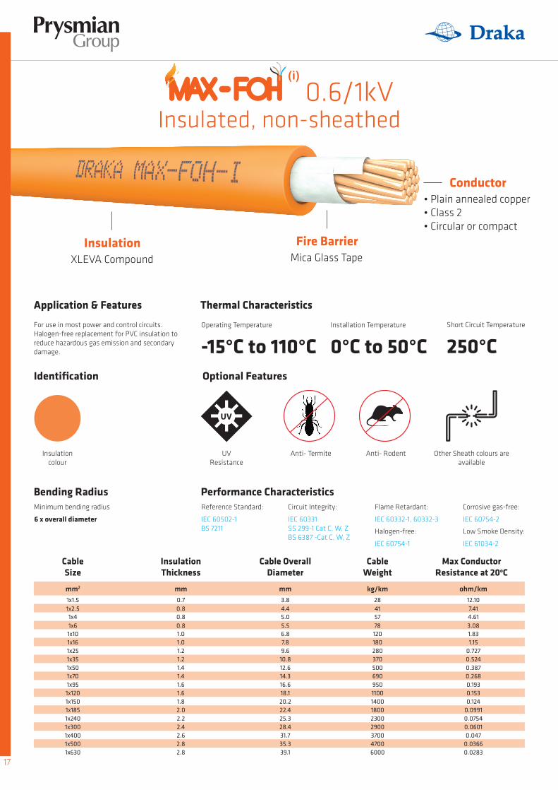
For use in most power and control circuits.Halogen-free replacement for PVC insulation to reduce hazardous gas emission and secondary damage.
Circuit Integrity:
IEC 60331SS 299-1 Cat C, W, ZBS 6387 -Cat C, W, Z
Reference Standard:
IEC 60502-1BS 7211
Flame Retardant:
IEC 60332-1, 60332-3
Halogen-free:
IEC 60754-1
Corrosive gas-free:
IEC 60754-2
Low Smoke Density:
IEC 61034-2
Minimum bending radius
6 x overall diameter
Insulation colour
UV Resistance
Anti- RodentAnti- Termite Other Sheath colours are available
Insulated, non-sheathed
• Plain annealed copper• Class 2• Circular or compact
Mica Glass TapeXLEVA Compound
Optional Features
Cable Size
mm2
1x1.51x2.51x41x61x101x161x251x351x501x701x951x1201x1501x1851x2401x3001x4001x5001x630
mm0.70.80.80.81.01.01.21.21.41.41.61.61.82.02.22.42.62.82.8
mm3.84.45.05.56.87.89.6
10.812.614.316.618.120.222.425.328.431.735.339.1
kg/km ohm/km28 12.1041 7.4157 4.6178 3.0812018028037050069095011001400180023002900370047006000
1.831.15
0.7270.5240.3870.2680.1930.1530.124
0.09910.07540.06010.047
0.03660.0283
Insulation Thickness
Cable OverallDiameter
Cable Weight
Max Conductor Resistance at 20oC
Operating Temperature
-15°C to 110°CInstallation Temperature
0°C to 50°CShort Circuit Temperature
250°C
17
0.6/1kV(i)

Application & Features Thermal Characteristics
Bending Radius Performance Characteristics
Identification
Conductor
Fire BarrierInsulation
Sheath
For use in most power and control circuits. Features XLPE Insulation for high operating temperatures, thermal short circuit rating and durability.
Minimum bending radius
6 x overall diameter
Outer Sheath UV Resistance
Anti- RodentInsulation Colour
Anti- Termite Other Sheath colours are available
Insulated, sheathed
• Plain annealed copper• Class 2• Circular or compact
Mica Glass Tape
XLPE CompoundLSHF Compound
Optional Features
Cable Size
mm2
1x1.51x2.51x41x61x101x161x251x351x501x701x951x1201x1501x1851x2401x3001x4001x5001x630
mm mm0.7 1.40.7 1.40.7 1.40.7 1.40.7 1.40.7 1.40.9 1.40.9 2.01.0 2.01.1 2.11.1 2.21.2 2.31.4 2.41.6 2.51.7 2.61.8 2.72.0 2.92.2 3.12.4 3.3
mm6.77.17.78.29.1
10.211.914.415.918.120.222.024.426.729.631.736.440.445.1
kg/km ohm/km63 12.1075 7.4196 4.61110 3.08160220330460600810
100013001600190025003200400050006400
1.831.15
0.7270.5240.3870.2680.1930.1530.124
0.09910.07540.06010.047
0.03660.0283
Insulation Thickness
SheathThickness
Cable OverallDiameter
Cable Weight
Max Conductor Resistance at 20oC
Circuit Integrity:
IEC 60331SS 299-1 Cat C, W, ZBS 6387 -Cat C, W, Z
Reference Standard:
IEC 60502-1
Flame Retardant:
IEC 60332-1, 60332-3
Halogen-free:
IEC 60754-1
Corrosive gas-free:
IEC 60754-2
Low Smoke Density:
IEC 61034-2
Operating Temperature
-15°C to 90°CInstallation Temperature
0°C to 50°CShort Circuit Temperature
250°C
18
0.6/1kV

Application & Features Thermal Characteristics
Bending Radius Performance Characteristics
Identification
Conductor
Fire BarrierInsulationSheath
For use in most power and control circuits. Features XLPE Insulation for high operating temperatures, thermal short circuit rating and durability.
Minimum bending radius
8 x overall diameter
Outer Sheath UV Resistance
Anti- Rodent
Core Colour
Anti- Termite Other Sheath colours are available
Insulated, sheathed
• Plain annealed copper• Class 2• Circular or compact
Mica Glass TapeXLPE CompoundLSHF Compound
Optional Features
Cable Size
mm2
2x1.52x2.52x42x62x102x162x252x352x502x702x952x1202x1502x1852x2402x3002x400
mm mm0.7 1.80.7 1.80.7 1.80.7 1.80.7 1.80.7 1.80.9 1.80.9 2.51.0 2.61.1 2.81.1 3.01.2 3.11.4 3.31.6 3.51.7 3.81.8 4.02.0 4.4
mm11.312.113.214.316.218.321.825.829.033.437.841.346.050.756.762.970.3
kg/km ohm/km170 12.10200 7.41260 4.61320 3.08370510740990120017002300280035004300560070008800
1.831.15
0.7270.5240.3870.2680.1930.1530.124
0.09910.07540.06010.047
Insulation Thickness
SheathThickness
Cable OverallDiameter
Cable Weight
Max Conductor Resistance at 20oC
Circuit Integrity:
IEC 60331SS 299-1 Cat C, W, ZBS 6387 -Cat C, W, Z
Reference Standard:
IEC 60502-1
Flame Retardant:
IEC 60332-1, 60332-3
Halogen-free:
IEC 60754-1
Corrosive gas-free:
IEC 60754-2
Low Smoke Density:
IEC 61034-2
Operating Temperature
-15°C to 90°CInstallation Temperature
0°C to 50°CShort Circuit Temperature
250°C
19
0.6/1kV, multi-core
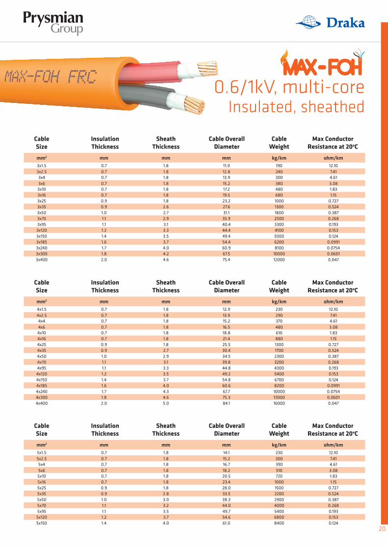
0.6/1kV, multi-coreInsulated, sheathed
Cable Size
Cable Size
Cable Size
mm2
mm2
mm2
3x1.5
4x1.5
5x1.5
3x2.5
4x2.5
5x2.5
3x4
4x4
5x4
3x6
4x6
5x6
3x10
4x10
5x10
3x16
4x16
5x16
3x25
4x25
5x25
3x35
4x35
5x35
3x50
4x50
5x50
3x70
4x70
5x70
3x95
4x95
5x95
3x120
4x120
5x120
3x150
4x150
5x150
3x185
4x185
3x240
4x240
3x300
4x300
3x400
4x400
mm
mm
mm
mm
mm
mm
0.7
0.7
0.7
1.8
1.8
1.8
0.7
0.7
0.7
1.8
1.8
1.8
0.7
0.7
0.7
1.8
1.8
1.8
0.7
0.7
0.7
1.8
1.8
1.8
0.7
0.7
0.7
1.8
1.8
1.8
0.7
0.7
0.7
1.8
1.8
1.8
0.9
0.9
0.9
1.8
1.8
1.8
0.9
0.9
0.9
2.6
2.7
2.8
1.0
1.0
1.0
2.7
2.9
3.0
1.1
1.1
1.1
2.9
3.1
3.2
1.1
1.1
1.1
3.1
3.3
3.5
1.2
1.2
1.2
3.3
3.5
3.7
1.4
1.4
1.4
3.5
3.7
4.0
1.6
1.6
3.7
4.0
1.7
1.7
4.0
4.3
1.8
1.8
4.2
4.6
2.0
2.0
4.6
5.0
mm
mm
mm
11.9
12.9
14.1
12.8
13.9
15.2
13.9
15.2
16.7
15.2
16.5
18.2
17.2
18.8
20.5
19.5
21.4
23.4
23.2
25.5
28.0
27.6
30.4
33.5
31.1
34.5
38.3
35.9
39.8
44.0
40.4
44.8
49.7
44.4
49.2
54.6
49.4
54.8
61.0
54.4
60.6
60.9
67.7
67.5
75.3
75.4
84.1
kg/km
kg/km
kg/km
ohm/km
ohm/km
ohm/km
190
230
230
12.10
12.10
12.10
240
290
300
7.41
7.41
7.41
300
370
390
4.61
4.61
4.61
380
480
510
3.08
3.08
3.08
480
610
720
680
880
1000
1000
1300
1500
1300
1700
2200
1800
2300
2900
2500
3200
4000
3300
4300
5400
4100
5400
6800
5000
6700
8400
6200
8200
8100
10000
10000
13000
12000
16000
1.83
1.83
1.83
1.15
1.15
1.15
0.727
0.727
0.727
0.524
0.524
0.524
0.387
0.387
0.387
0.268
0.268
0.268
0.193
0.193
0.193
0.153
0.153
0.153
0.124
0.124
0.124
0.0991
0.0991
0.0754
0.0754
0.0601
0.0601
0.047
0.047
Insulation Thickness
Insulation Thickness
Insulation Thickness
SheathThickness
SheathThickness
SheathThickness
Cable OverallDiameter
Cable OverallDiameter
Cable OverallDiameter
Cable Weight
Cable Weight
Cable Weight
Max Conductor Resistance at 20oC
Max Conductor Resistance at 20oC
Max Conductor Resistance at 20oC
20
Application & Features Thermal Characteristics
Bending Radius Performance Characteristics
Identification
Conductor
Fire Barrier
InsulationSheath
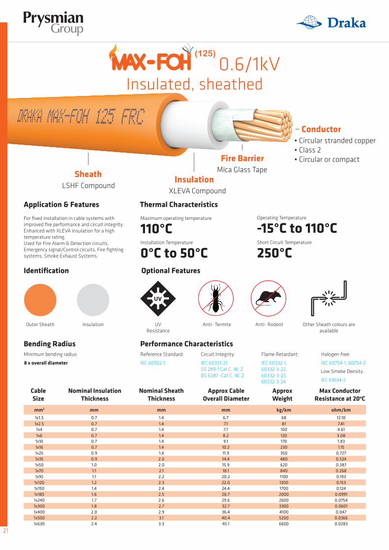
For fixed installation in cable systems with improved fire performance and circuit integrity. Enhanced with XLEVA insulation for a high temperature rating.Used for Fire Alarm & Detection circuits, Emergency signal/Control circuits, Fire fighting systems, Smoke Exhaust Systems.
Circuit Integrity:
IEC 60331-21SS 299-1 Cat C, W, ZBS 6387 -Cat C, W, Z
Reference Standard:
IEC 60502-1
Flame Retardant:
IEC 60332-1, 60332-3-22,60332-3-23,60332-3-24
Halogen-free:
IEC 60754-1, 60754-2
Low Smoke Density:
IEC 61034-2
Minimum bending radius
8 x overall diameter
Outer Sheath Insulation UV Resistance
Anti- RodentAnti- Termite Other Sheath colours are available
• Circular stranded copper• Class 2• Circular or compact
Mica Glass Tape
XLEVA CompoundLSHF Compound
Optional Features
Cable Size
mm2
1x1.51x2.51x41x61x101x161x251x351x501x701x951x1201x1501x1851x2401x3001x4001x5001x630
mm0.70.70.70.70.70.70.90.91.01.11.11.21.41.61.71.82.02.22.4
mm mm1.4 6.71.4 7.11.4 7.71.4 8.21.4 9.11.4 10.21.4 11.92.0 14.42.0 15.92.1 18.12.2 20.22.3 22.02.4 24.42.5 26.72.6 29.62.7 32.72.9 36.43.1 40.43.3 45.1
kg/km ohm/km68 12.1081 7.41
100 4.61120 3.08170230350480620840110013001700200026003300410052006600
1.831.15
0.7270.5240.3870.2680.1930.1530.124
0.09910.07540.06010.047
0.03660.0283
Nominal Insulation Thickness
Nominal Sheath Thickness
Approx Cable Overall Diameter
ApproxWeight
Max Conductor Resistance at 20oC
Operating Temperature
-15°C to 110°CMaximum operating temperature
110°CInstallation Temperature
0°C to 50°CShort Circuit Temperature
250°C
21
0.6/1kVInsulated, sheathed
(125)
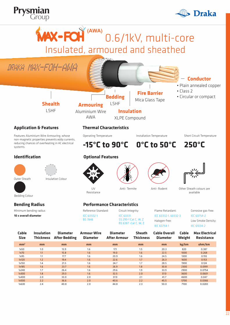
Application & Features Thermal Characteristics
Bending Radius Performance Characteristics
Identification
Conductor
Fire Barrier
Insulation
BeddingArmouringShealth
Features Aluminium Wire Armouring, whose non-magnetic properties prevents eddy currents, reducing chances of overheating in AC electrical systems.
Minimum bending radius
10 x overall diameter
Outer Sheath
UV Resistance
Anti- Rodent
Insulation Colour
Bedding Colour
Anti- Termite Other Sheath colours are available
Operating Temperature
-15°C to 90°CInstallation Temperature
0°C to 50°CShort Circuit Temperature
250°C
Insulated, armoured and sheathed
• Plain annealed copper• Class 2• Circular or compact
Mica Glass Tape
XLPE Compound
LSHF
Aluminium Wire AWA
LSHF
Optional Features
Cable Size
mm2
1x501x701x951x1201x1501x1851x2401x3001x4001x5001x630
mm mm mm mm1.0 13.9 1.6 17.11.1 15.8 1.6 19.01.1 17.7 1.6 20.91.2 19.4 1.6 22.61.4 21.5 1.6 24.71.6 23.7 1.6 26.91.7 26.4 1.6 29.61.8 29.3 1.6 32.52.0 33.0 2.0 37.02.2 36.6 2.0 40.62.4 40.8 2.0 44.8
mmmm20.31.522.51.624.51.626.31.728.51.730.81.833.91.937.02.041.72.145.52.250.02.3
kg/km ohm/km8201000130016001900230029003600460057007100
0.3870.2680.1930.1530.124
0.09910.07540.06010.047
0.03660.0283
Insulation Thickness
Diameter After Bedding
Armour Wire Diameter
Diameter After Armour
Cable OverallDiameter
Sheath Thickness
Cable Weight
Max Electrical Resistance
Circuit Integrity:
IEC 60331SS 299-1 Cat C, W, ZBS 6387 -Cat C, W, Z
Reference Standard:
IEC 60502-1BS 7846
Flame Retardant:
IEC 60332-1, 60332-3
Halogen-free:
IEC 60754-1
Corrosive gas-free:
IEC 60754-2
Low Smoke Density:
IEC 61034-2
22
0.6/1kV, multi-core(AWA)
• Circular stranded copper• Class 2• Circular or compact

Application & Features Thermal Characteristics
Bending Radius Performance Characteristics
Identification
Conductor
Fire Barrier
InsulationBedding
Features galvanised Steel Wire Armour, which enables cable to withstand high pulling loads. Commonly used in a whole range of industries including building and construction, rail and transport and particularly useful in external or underground projects.
Minimum bending radius
10 x overall diameter
UV Resistance
Anti- RodentAnti- Termite Other Sheath colours are available
Insulated, armoured and sheathed
• Plain annealed copper• Class 2• Circular or compact
Mica Glass Tape
XLPE CompoundLSHF Compound
Optional Features
Cable Size
mm2
2x1.52x2.52x42x62x102x162x252x352x502x702x952x1202x1502x1852x2402x3002x400
mm mm mm mm mm0.7 9.7 0.9 11.4 1.80.7 10.5 0.9 12.3 1.80.7 11.6 0.9 13.3 1.80.7 12.7 0.9 14.5 1.80.7 14.6 1.25 17.0 1.80.7 16.7 1.25 19.2 1.80.9 20.2 1.6 23.3 1.80.9 22.7 1.6 25.9 1.81.0 25.8 1.6 28.9 1.91.1 29.7 1.6 32.9 2.01.1 34.1 2.0 38.0 2.11.2 37.4 2.0 41.4 2.21.4 41.7 2.0 45.7 2.41.6 46.4 2.5 51.3 2.51.7 51.9 2.5 56.8 2.71.8 58.0 2.5 63.0 2.92.0 64.6 2.5 69.5 3.1
mm15.116.017.018.220.722.927.029.632.937.042.445.950.656.562.368.975.8
kg/km ohm/km410 12.10460 7.41530 4.61620 3.08810
10001400180022002800390046005500700086001000011000
1.831.15
0.7270.5240.3870.2680.1930.1530.124
0.09910.07540.06010.047
Insulation Thickness
Diameter After Bedding
Amour Wire Diameter
Diameter After Armour
SheathThickness
Cable OverallDiameter
Cable Weight
Max electrical resistance
ArmouringShealthGalvanised Steel
WireLSHF
Outer Sheath
Core ColourBedding Colour
Circuit Integrity:
IEC 60331SS 299-1 Cat C, W, ZBS 6387 -Cat C, W, Z
Reference Standard:
IEC 60502-1BS 7846
Flame Retardant:
IEC 60332-1, 60332-3
Halogen-free:
IEC 60754-1
Corrosive gas-free:
IEC 60754-2
Low Smoke Density:
IEC 61034-2
Operating Temperature
-15°C to 90°CInstallation Temperature
0°C to 50°CShort Circuit Temperature
250°C
23
0.6/1kV, multi-core(SWA)

0.6/1kV, multi-coreInsulated, armoured
and sheathedCable Size
Cable Size
Cable Size
mm2
mm2
mm2
3x1.5
4x1.5
5Gx1.5
3x2.5
4x2.5
5Gx2.5
3x4
4x4
5Gx4
3x6
4x6
5Gx6
3x10
4x10
5Gx10
3x16
4x16
5Gx16
3x25
4x25
5Gx25
3x35
4x35
5Gx35
3x50
4x50
5Gx50
3x70
4x70
5Gx70
3x95
4x95
5Gx95
3x120
4x120
5Gx120
3x150
4x150
5Gx150
3x185
4x185
3x240
4x3004x240
3x300
4x400
3x400
mm
mm
mm
mm
mm
mm
mm
mm
mm
mm
mm
mm
mm
mm
mm
0.7
0.7
0.7
10.3
11.3
12.5
0.9
0.9
0.9
12.0
13.0
14.2
1.8
1.8
1.8
0.7
0.7
0.7
11.2
12.3
13.6
0.9
0.9
1.25
12.9
14.0
16.1
1.8
1.8
1.8
0.7
0.7
0.7
12.3
13.6
15.1
0.9
1.25
1.25
14.1
16.0
17.5
1.8
1.8
1.8
0.7
0.7
0.7
13.6
14.9
16.6
1.25
1.25
1.25
16.0
17.4
19.0
1.8
1.8
1.8
0.7
0.7
0.7
15.6
17.2
18.9
1.25
1.25
1.6
18.0
19.6
22.0
1.8
1.8
1.8
0.7
0.7
0.7
17.9
19.8
21.8
1.25
1.25
1.6
20.3
22.9
24.9
1.8
1.8
1.8
0.9
0.9
0.9
21.6
23.9
26.4
1.6
1.6
1.6
24.7
27.1
29.6
1.8
1.8
1.9
0.9
0.9
0.9
24.3
27.0
29.9
1.6
1.6
1.6
27.4
30.1
33.0
1.8
1.9
2.0
1.0
1.0
1.0
27.6
31.1
34.6
1.6
1.6
2.0
30.7
35.0
38.5
1.9
2.1
2.2
1.1
1.1
1.1
32.5
36.0
39.9
2.0
2.0
2.0
36.4
39.9
43.9
2.1
2.2
2.3
1.1
1.1
1.1
36.5
40.6
45.5
2.0
2.0
2.5
40.5
44.5
50.4
2.2
2.3
2.5
1.2
1.2
1.2
40.1
45.0
50.0
2.0
2.0
2.5
44.0
49.9
54.9
2.3
2.5
2.7
1.4
1.4
1.4
45.2
50.2
56.2
2.5
2.5
2.5
50.1
55.1
61.1
2.5
2.7
2.8
1.6
1.6
49.8
55.8
2.5
2.5
54.7
60.7
2.6
2.8
1.7
1.81.7
56.0
69.362.3
2.5
2.52.5
60.9
74.267.2
2.8
3.23
1.8
2.0
62.3
77.6
2.5
3.15
67.2
83.8
3.0
3.5
2.0 69.3 2.5 74.2 3.3
mm
mm
mm
15.7
16.7
17.9
16.6
17.7
19.8
17.8
19.7
21.2
19.7
21.1
22.7
21.7
23.3
25.7
24.0
26.6
28.6
28.4
30.8
33.5
31.2
34.0
37.2
34.7
39.3
43.1
40.7
44.5
48.6
45.0
49.3
55.5
48.8
55.0
60.4
55.2
60.6
66.8
60.0
66.4
66.7
80.773.3
73.3
90.9
81.0
kg/km
kg/km
kg/km
ohm/km
ohm/km
ohm/km
440
500
530
12.10
12.10
12.10
510
570
720
7.41
7.41
7.41
590
790
850
4.61
4.61
4.61
810
930
1000
3.08
3.08
3.08
960
1100
1400
1200
1500
1800
1700
2100
2500
2200
2600
3100
2700
3700
4300
3900
4700
5700
4900
6000
7800
5800
7800
9400
7500
9400
11000
8800
11000
11000
1600014000
13000
22000
16000
1.83
1.83
1.83
1.15
1.15
1.15
0.727
0.727
0.727
0.524
0.524
0.524
0.387
0.387
0.387
0.268
0.268
0.268
0.193
0.193
0.193
0.153
0.153
0.153
0.124
0.124
0.124
0.0991
0.0991
0.0754
0.06010.0754
0.0601
0.047
0.047
Insulation Thickness
Insulation Thickness
Insulation Thickness
Diameter After Bedding
Diameter After Bedding
Diameter After Bedding
Amour Wire Diameter
Amour Wire Diameter
Amour Wire Diameter
Diameter After Armour
Diameter After Armour
Diameter After Armour
SheathThickness
SheathThickness
SheathThickness
Cable OverallDiameter
Cable OverallDiameter
Cable OverallDiameter
Cable Weight
Cable Weight
Cable Weight
Max electrical resistance
Max electrical resistance
Max electrical resistance
24
(SWA)
A. Introduction to Cable MaterialsB. Selection of Cross-Sectional Area of ConductorC. Current Ratings and Voltage Drop Table (Unarmoured Cables)D. Current Ratings and Voltage Drop Table (Armoured Cables)E. Short Circuit RatingsF. Cables & Drum Handling and Storage ProcedureG. Identification of Cable Cores
Appendix
25

Introduction to Cable MaterialsInsulation
ThermosetsCross-linked Polyethylene (XLPE)
ThermoplasticPolyvinyl Chloride (PVC) & Polyethylene (PE)
In the manufacture of electrical cables, safety and reliability are the biggest considerations. The materials that are selected must be stable, reliable, durable, able to withstand the environment and safe to use. Materials used as insulation for cables must meet the following:1. Providing safe insulation of the line conductors with minimum loss in electrical energy.2. Exhibiting stable mechanical properties under normal conditions.3. Possessing consistent electrical and mechanical properties over long period of use and over wide temperature ranges.4. Exhibiting inert chemical properties which make it resistant to most chemicals.
Extruded insulation can be classified into two categories, namely Thermoplastic materials and Thermoset materials.
Thermoplastic materials tend to lose their form with continuous heating, while thermoset materials tend to maintain their form. This means that cables with thermoset materials can operate at higher temperatures than thermoplastic cables.
The thermoplastic nature of the PE can be converted into a thermally stable thermosetting compound by the process of cross-linking. In the process of cross-linking, perpendicular chemical bonds are formed between parallel chains of the PE molecules. The parallel, loose & twodimensional molecular structure is converted into a cellular, three-dimensional polymeric structure.
XLPE exhibits a durable and excellent insulating material which exhibits the following advantages over conventional PE:- Suitable for continuous operating temperature up to 90°C.- high thermal short circuit rating (250°C).- Excellent electrical properties maintained over the full temperature range.- Excellent water resistance and low permeability to water.- Excellent chemical resistance to inorganic salts, oils, alkaline, acids ad organic solvents.- High durability and long operation life.- Halogen Free
PVC and PE display good characteristics for cable insulation, and are inherently tough and physically resistant to chemicals, moisture and abrasion. The problems with these materials are apparent when subjected to high and continuous heat:
1. PVC is known to emit smoke and form hydrochloric acid (a highly toxic and corrosive chemical) when they come in contact with water. As such, PVC-free cable insulation is frequently preferred in applications where smoke is a major hazard (notably in tunnels and rapid transit areas).
2. The PE polymer is made up of linear chains of independent PE molecules loosely held together by weak molecular bonds. These weak molecular bonds break when subjected to temperature above 70°C, causing the individual molecules to slide over one another.
The resultant PE polymer starts to change its shape and consistency and become soft and plastic-like in nature. For applications with operating temperatures higher than 70°C, cross-linked polyethylene (XLPE) is preferred.
Material
Features
Resistance
Temperature Ratings
Behaviour in high heat environments
High Electrical Strength, Insulation Resistance
Moisture, abrasions
- 60°C to 105°C
Emits smoke & Hydrochloric Acid
PVC
Excellent electrical insulating propertiesStable mechanical characteristic
Chemicals, Moisture
-60°C to 80°C
Changes shape and consistency,Softens in texture
PE
Appendix A
26

Cross-linked Ethylene-vinyl Acetate (XLEVA)
Table A1Comparison for Insulation Materials
Note:A B --- + ++ +++
Named as LSHF for all non-sheathed cables.Normal type, high temperature rating available upon request.PoorFairGoodExcellent
ConclusionBased on the three salient qualities for fire performance cables, we find that XLPE and XLEVA are the better-performing choices for insulation, which also explains their preference for safety in the industry.
Ethylene-vinyl acetate(EVA) is a polymer that has the softness and flexibility elastomeric materials, yet they can be processed like a thermoplastic. These properties are further enhanced to achieve thermal stability by the process of cross-linking to form a cellular three-dimensional polymeric structure.
The resultant XLEVA compound exhibits a more durable and excellent insulating material while maintaining its flexibility. Based on the specific formulation, XLEVA compound can withstand a temperature rating up to 110°C and display an excellent flame retardant capability. It contains no halogens and has a temperature index of more than 250°C, currently the highest among mostinsulation materials.
Property
Chemical Name
Density
Volume Resistivity
Dielectric Constant
Tensile Strength
Elongation-at-break
Flame Retardant Property
Water resistance
Weather resistance
Ozone resistance
Solvent resistance
Resistance to oil
Resistance to heat deformation
Max. RatedTemperature
Normal
Short Circuit
°C 70 70 90 110B
160
1.2 - 1.4
10E15
3 - 5
12 - 14
200 - 450
++
++
++
++
---
++
---
Ohm-cm
N / mm²
%
0.92 - 0.94
10E16
2.0 - 2.3
12 - 14
500 - 650
+
+++
++
++
++
+++
+
0.92 - 0.95
10E16
2.3 - 2.5
13 - 18
200 - 350
+
+++
++
++
+
+++
+++
1.5 - 1.55
10E14
4 - 6
10 - 14
110 - 200
+++
+++
++
++
+
++
+++
200 250 250°C
Unit Insulation Materials
PVC
Polyvinyl Chloride
Polyethylene Cross-linkedPolyethylene
Cross-linked Ethylene-vinyl
Acetate
PE XLPE XLEVAA
27
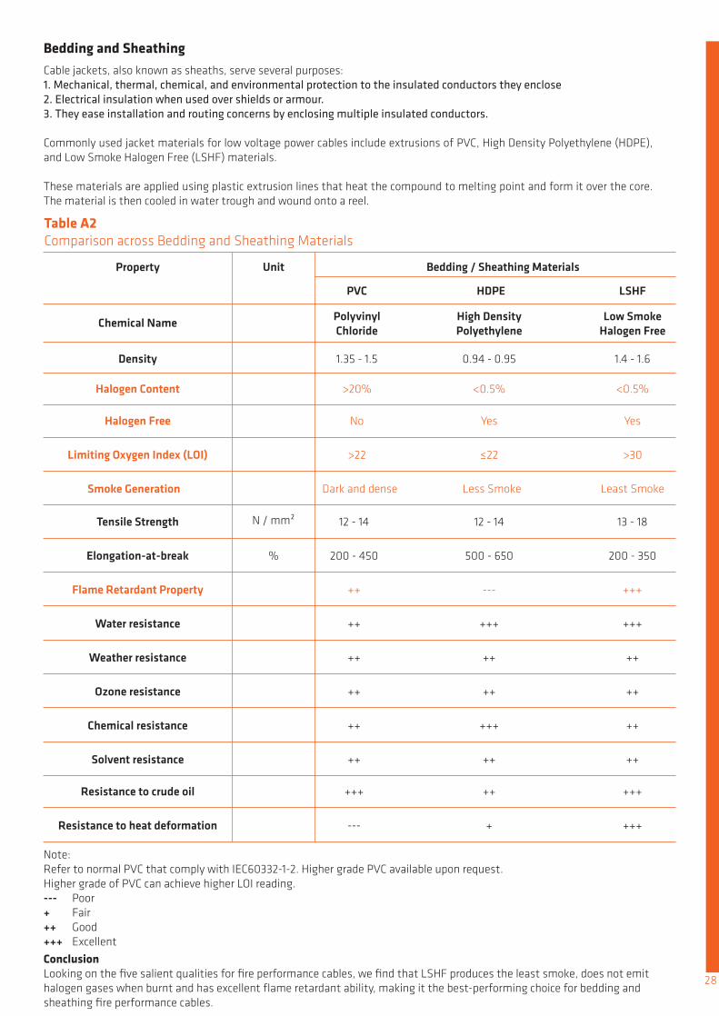
ConclusionLooking on the five salient qualities for fire performance cables, we find that LSHF produces the least smoke, does not emit halogen gases when burnt and has excellent flame retardant ability, making it the best-performing choice for bedding and sheathing fire performance cables.
Bedding and Sheathing
Table A2Comparison across Bedding and Sheathing Materials
Note:Refer to normal PVC that comply with IEC60332-1-2. Higher grade PVC available upon request.Higher grade of PVC can achieve higher LOI reading.--- + ++ +++
PoorFairGoodExcellent
Cable jackets, also known as sheaths, serve several purposes:1. Mechanical, thermal, chemical, and environmental protection to the insulated conductors they enclose2. Electrical insulation when used over shields or armour.3. They ease installation and routing concerns by enclosing multiple insulated conductors.
Commonly used jacket materials for low voltage power cables include extrusions of PVC, High Density Polyethylene (HDPE), and Low Smoke Halogen Free (LSHF) materials.
These materials are applied using plastic extrusion lines that heat the compound to melting point and form it over the core. The material is then cooled in water trough and wound onto a reel.
Property
Chemical Name
Density
Halogen Content
Halogen Free
Limiting Oxygen Index (LOI)
Smoke Generation
Tensile Strength
Elongation-at-break
Flame Retardant Property
Water resistance
Weather resistance
Ozone resistance
Chemical resistance
Solvent resistance
Resistance to crude oil
Resistance to heat deformation
1.35 - 1.5
>20%
No
>22
Dark and dense
12 - 14
200 - 450
++
++
++
++
++
++
+++
---
N / mm²
%
0.94 - 0.95
<0.5%
Yes
≤22
Less Smoke
12 - 14
500 - 650
---
+++
++
++
+++
++
++
+
1.4 - 1.6
<0.5%
Yes
>30
Least Smoke
13 - 18
200 - 350
+++
+++
++
++
++
++
+++
+++
Unit Bedding / Sheathing Materials
PVC
Polyvinyl Chloride
High DensityPolyethylene
HDPE
Low Smoke Halogen Free
LSHF
28

In order to choose the right power cable, one has to consider:
• the current rating
• the installation methods
• maximum safe length at short circuit
• the short circuit ratio
• the frequency and harmonic current
• the voltage drop
• the ambient temperature
Selection Of Cross-Sectional Area Of Conductor
Voltage DropAnother important factor for the determination of the conductor size is the voltage drop. The voltage drop of the cable at a given current is caused by losses in the cable. In case of a too high voltage drop, it is necessary to choose a bigger conductor size. The voltage drop in a cable demotes the difference in voltage at the beginning and at the end of the cable. It depends on:• the current carried• the power factor• the length of the cable• the resistance of the cable• reactance of the cable
The permissible voltage drop is usually stated as a percentage of the circuit voltage.
According to CP5:1998 regulation 525-01-01, it is stipulated that the total voltage drop for any particular cable run must be such that the voltage drop in the circuit of which the cable forms a part does not exceed 4% of the nominal voltage of the supply.
Current RatingWhen electric current flows through the conductor of a cable, the electrical resistance of the conductor generates heat. When a temperature greater than that allowed is reached by the cable due to heat generation, a larger conductor size (with lower electrical resistance) has to be selected. Other important considerations are methods of installation of the cable and ambient temperature.
Calculation which takes into account all criteria are described in IEC 60287 and are rather complex. In general, preferences is given to standard current rating tables which are issued by national standardization bureaus.
Appendix B
29

Selection of Cable based on Voltage Drop and Current using Tables
Guided example to using our Current Rating / Voltage Drop Tables
Maximum permissible voltage drop
Voltage drop
V = Vdrop x I x L
Since the actual power factor of the load is usually not known, the most practical approach to the question of the voltage drop is to assume the worst conditions, i.e. power factor equal to one and the conductor is at maximum operating temperature. The voltage drop values given in the tables are based on these assumptions.
The values of the voltage drop (Vd) are tabulated for a current of one Ampere for a 1 metre run, the value of voltage drop needs to be multiplied by the length of the run, in metre, and by the current, in Ampere that the cables are to carry.
Given that the supply voltage is 415V, 3-phase 50Hz and that the cable used is a 4C MAX-FOH-SWA.
Required cable is to be installed direct in ground and to carry a 250A load per phase over a route length of 100m. Cable installation is to be in compliance with BS 7671-2008 regulation.
Select the impedance value z from Table D4 (Voltage Drop for Multi-core Armoured cables) such that the z is equal to, or less than Vdrop 0.66mV/Am.
It will be seen that the closest value is z(4-core cable) = 0.60 mV/Am, therefore arriving at a required conductor size of 70mm2.
Vmax = 4% of 415VVmax = 16.65V
Vdrop = = =Vmax 16.6V
I x L 250 x 1000.66mV/Am
WhereV = Voltage (V)Vdrop = Approx. Voltage drop (V/Am)I = Current (A)L = Route Length (m)
30
Single-core cablesConditionsThese tables apply to cables that meet these construction and environment conditions:
CURRENT-CARRYING CAPACITY (amperes):
Thermosetting (XLPE) insulation
With or without LSHF sheathing
Construction Environment
Ambient Temperature: 30oC
Conductor Operating Temperature: 90oC
Current Ratings And Voltage Drop Table (Unarmoured Cables)
Table C1Current Rating - Single-core Unarmoured
Conductor cross-
sectional area
2 cables, single
phase a.c or d.c
2 cables, single
phase a.c or d.c
2 cables, single phase
a.c or d.c flat and
touching
3 or 4 cables, three
phase a.c.
3 or 4 cables, three
phase a.c.
3 or 4 cables, three
phase a.c. flat and
touching or trefoil
2 cables, single
phase a.c. or d.e. flat
3 cables, three
phase a.c. flat
3 cables, three
phase a.c. trefoil
Horizontal Vertical
2 cables, single-phase a.c. or d.c. or 3 cables three phase a.e. flat
(mm2) (A) (A) (A) (A) (A) (A) (A) (A) (A) (A) (A)
2.5 26 23 31 28 34 31 - - - - -
1.5 19 17 23 20 25 23 - - - - -
1 14 13 17 15 19 17.5 - - - - -
4 35 31 42 37 46 41 - - - - -
6 45 40 54 48 59 54 - - - - -
10 61 54 75 66 81 74 - - - - -
16 81 73 100 88 109 99 - - - - -
25 106 95 133 117 143 182 161
35 131 117 164 144 176 226 201
50 158 141 198 175 228 275 246
70 200 179 253 222 293 353 318
95 241 216 306 269 355 430 389
120 278 249 354 312 413 500 454
150 318 285 393 342 476 577 527
185 362 324 449 384 545 661 605
240 424 380 528 450 644 781 719
300 486 435 603 514 743 902 833
400 - - 683 584 868 1085 1008
500 - - 783 666 990 1253 1169
630 - - 900 764 1130 1454 1362
800 - - - - 1288 1581 1485
1000 - - - - 1323
161130 141 135
200161 176 169
242209 216 207
310268 279 268
377326 342 328
437379 400 383
504436 464 444
575500 533 510
679590 634 607
783681 736 703
940793 868 823
1083904 998 946
12541033 1151 1088
13581179 1275 1214
15201323 1435 1349 1775 1671
Reference Method A (enclosed in
conduit in thermally insulating wall etc.)
Reference Method B (enclosed in conduit
on a wall or in trucking etc.)
Reference Method C (clipped direct)
Reference Method G (in free air)
Spaced by one cable diameter
Reference Method F (in free air or on a perforated
cable tray etc horizontal or vertical etc)
Touching
21 3 4 65 7 8 9 10 11 12
Appendix C
31
Conductor cross-
sectional area
2 cables, d.c.
(mm2)(mV / A
/ m)(mV / A / m) (mV / A / m) (mV / A / m) (mV / A / m) (mV / A / m) (mV / A / m) (mV / A / m)
2.5 19
1.5 31
1 46 46 46 46 40 40 40 40
31 31 31 27 27 27 27
19 19 19 16 16 16 16
1.85 1.85 1.85 1.60 1.60 1.60 1.60
1.15
0.86
0.59
0.43
0.34
0.28
0.22
0.170
0.135
0.110
0.085
0.068
0.055
0.047
1.15
0.86
0.59
0.43
0.34
0.28
0.22
0.170
0.135
0.110
0.088
0.071
0.059
0.050
1.15
0.86
0.59
0.43
0.34
0.28
0.22
0.170
0.140
0.110
0.090
0.074
0.062
0.055
1.15
0.87
0.60
0.44
0.35
0.29
0.23
0.185
0.150
0.125
0.100
0.088
-
-
1.35
0.99
0.68
0.49
0.39
0.32
0.25
0.195
0.155
0.125
0.098
0.078
0.064
0.054
1.35 1.35
1.00 0.99
0.70 0.68
0.51 0.49
0.41 0.39
0.33 0.32
0.27 0.26
0.21 0.20
0.175 0.160
0.140 0.130
0.120 0.105
0.100 0.086
- 0.072
- 0.063
0.31 0.190 0.28 0.27 0.165 0.190 0.27
0.26
0.26
0.25
0.25
0.24
0.24
0.24
0.24
0.24
0.24
0.24
0.23
0.23
0.23
0.180
0.180
0.175
0.170
0.165
0.165
0.165
0.165
0.160
0.160
0.160
0.160
0.155
0.155
0.155
0.155
0.150
0.145
0.140
0.140
0.140
0.140
0.140
0.135
0.135
0.135
0.130
0.130
0.25
0.25
0.24
0.23
0.23
0.23
0.23
0.22
0.22
0.22
0.22
0.21
-
-
0.27
0.27
0.26
0.26
0.25
0.25
0.25
0.25
0.25
0.24
0.24
0.24
0.24
0.24
0.29 0.180
0.29 0.180
0.1750.28
0.27 0.170
0.26 0.165
0.26 0.165
0.26 0.165
0.26 0.160
0.25 0.160
0.25 0.155
0.25 0.155
0.25 0.155
- 0.150
- 0.150
1.90 1.85 1.85 1.65 1.60 1.60 1.65
1.20
0.89
0.65
0.49
0.42
0.37
0.33
0.29
0.27
0.26
0.25
0.24
0.24
0.24
1.15
0.87
0.62
0.46
0.38
0.32
0.28
0.24
0.21
0.195
0.180
0.170
0.165
0.165
1.15
0.87
0.61
0.45
0.37
0.31
0.26
0.22
0.195
0.175
0.160
0.150
0.145
0.140
1.15
0.90
0.65
0.50
0.42
0.37
0.32
0.29
0.27
0.25
0.24
0.23
-
-
1.35
1.00
0.73
0.56
0.47
0.41
0.36
0.31
0.29
0.27
0.26
0.25
0.25
0.24
1.35 1.35
1.05 1.00
0.75 0.71
0.58 0.52
0.48 0.43
0.43 0.36
0.37 0.30
0.33 0.25
0.31 0.22
0.29 0.20
0.28 0.175
0.27 0.175
- 0.170
- 0.165
12 12 12 10 10 10 10
7.9 7.9 7.9 6.8 6.8 6.8 6.8
4 12
6 7.9
10 4.7 4.7 4.7 4.7 4.0 4.0 4.0 4.0
16 2.9 2.9 2.9 2.5 2.5 2.5 2.5
r r r r r r rx x x x x x xz z z z z z z
25 1.85
35 1.35
50 0.99
70 0.68
95 0.49
120 0.39
150 0.32
185 0.25
240 0.190
300 0.155
400 0.120
500 0.093
630 0.072
800 0.056
1000 0.045
Reference Methods A & B (enclosed
in conduit or trunking)
Reference Methods A & B (enclosed
in conduit or trunking)
Reference Methods C, F & G (clipped direct on tray or in
free air)
Reference Methods C, F & G (clipped direct on tray or in free air)
Cables touching
Cables touching,
Trefoil
Cables touching,
Flat
Cables spaced*,
FlatCables
spaced*21 3 4 65 7 8 9
Table C2Voltage Drop - Single-core Unarmoured
Current Ratings And Voltage Drop Table (Unarmoured Cables)
VOLTAGE DROP (per ampere per metre):
32

*with or without a protective conductor
Table C3Current Rating - Multi-core Unarmoured
Thermosetting (XLPE) insulation
With or without LSHF sheathing
Construction Environment
Ambient Temperature: 30oC
Conductor Operating Temperature: 90oC
CURRENT-CARRYING CAPACITY (amperes):
Conductor cross-
sectional area
1 two-core cable*, single
phase a.c. or d.c.
1 two-core
cable*, single
phase a.c. or d.c.
1 two-core cable*, single
phase a.c. or d.c.
1 three- or four-core
cable*, three
phase a.c.
1 three- or four-core
cable*, three
phase a.c.
1 three- or four-core
cable*, three
phase a.c.
1 two-core cable*, single
phase a.c. or d.c.
1 three- or four-core
cable*, three
phase a.c.
(mm2) (A) (A) (A) (A) (A) (A) (A) (A)
2.5 25 22 30 26 33 30 36 32
1.5 18.5 16.5 22 19.5 24 22 26 23
1 14.5 13 17 15 19 17 21 18
4 33 30 40 35 45 40 49 42
6 42 38 51 44 58 52 63 54
10 57 51 69 60 80 71 86 75
16 76 68 91 80 107 96 115 100
25 99 89 119 105 138
35 121 109 146 128 171
50 145 130 175 154 209
70 183 164 221 194 269
95 220 197 265 233 328
120 253 227 305 268 382
150 290 259 334 300 441
185 329 295 384 340 506
240 386 346 459 398 599
300 442 396 532 455 693
400 - - 625 536 803
149119 127
185147 158
225179 192
289229 246
352278 298
410322 346
473371 399
542424 456
641500 538
741576 621
865667 741
Reference Method A (enclosed in conduit in
thermally insulating wall etc.)
Reference Method B (enclosed in conduit on a
wall or in trucking etc.)
Reference Method C (clipped direct)
Reference Method E (in free air or on a perforated
cable tray etc horizontal or vertical etc)
21 3 4 65 7 8 9
Current Ratings And Voltage Drop Table (Unarmoured Cables)Multi-core cablesThese tables apply to cables that meet these construction and environment conditions:
33

Table C4Voltage Drop - Multi-core Unarmoured
VOLTAGE DROP (per ampere per metre):
Conductor cross-sectional area
Two-core cable, d.c.
(mm2) (mV / A / m)(mV / A / m) (mV / A / m)
2.5
1.5
1 46 46 40
31 31 27
19 19 16
0.160 0.140
0.155 0.135
0.155 0.135
0.150 0.130
0.150 0.130
0.145 0.130
0.145 0.125
0.145 0.125
0.140 0.125
0.140
0.140
0.120
0.120
1.90 1.65
1.35 1.15
1.00 0.87
0.69 0.60
0.52 0.45
0.42 0.37
0.35 0.30
0.29 0.26
0.24 0.21
0.21 0.185
0.190 0.165
1.85 1.60
1.35 1.15
0.99 0.86
0.67 0.59
0.50 0.43
0.40 0.34
0.32 0.28
0.26 0.22
0.200 0.175
0.160 0.140
0.130 0.115
12 12 10
7.9 7.9 6.8
2.9
1.85
1.35
0.98
0.67
0.49
0.39
0.31
0.25
0.195
0.155
0.120
2.9 2.5
4
6
10 4.7 4.7 4.0
16
x xz zr r
25
35
50
70
95
120
150
185
240
300
400
Two-core cable, single
phase a.c.
Three- or four-core cable, three-phase a.c.
21 3 4
Current Ratings And Voltage Drop Table (Unarmoured Cables)
34

These tables are to supplement current ratings for Tables C1 and C3.
Table C6Correction factors for multiple multi-core cables
Correction Factors
Table C5Correction factors for multiple single core cables installed in free air
Notes:1. Factors are given for single layers of cables (for trefoil groups) as shown in the tables and DO NOT apply when cables are installed in more than one layer touching each other. Values for such installations may be significantly lower and must be determined by an appropriate method.2. Values are given for a vertical spacing between trays of 300mm. For closer spacing the factors should be reduced.3. Values are given for a horizontal spacing between trays of 255mm with tray mounted back to back. For closer spacing the factors should be reduced.4. For circuits having more than one cable in parallel per phase, each set of three conductors should be considered as a circult for the purposes of this table.
Unperforated trays (Note 2) H
Number of trays 1 2 3
Number of three-phase circuits (Note 4) Use as a multiplier to
rating for
Installation method (See Note 1)
Perforated trays(Note 2)
Vertical perforated trays (Note 3)
Ladder support cleats, etc(Note 2)
Unperforated trays(Note 2)
Perforated trays(Note 2)
Vertical perforated trays
(Note 3)
Ladder supports, cleats, etc(Note 2)
J
K
L
H
J
K
L
123
Touching
Touching
Touching
Touching
Touching
Touching
Spaced
Spaced
Spaced
Spaced
Touching
Touching
123
12
123
123
123
12
123
0.950.920.90
0.950.950.90
0.950.90
1.000.950.95
1.000.950.95
1.000.950.95
1.001.00
1.000.950.95
0.900.850.80
0.900.850.85
0.850.85
0.950.900.90
0.950.900.90
1.000.950.90
0.900.90
1.000.950.95
0.850.800.75
0.850.800.80
------
0.950.900.85
0.950.850.85
0.950.900.85
0.900.85
1.000.950.90
Three cables in horizontal
formation
Three cables in vertical formation
Three cables in horizontal
formation
Three cables in trefoil formation
Notes:1. Factors apply to single layer groups of cables as shown above and do NOT apply when cables are installed in more than one layer touching each other. Values for such installations may be significantly lower and must be determined by an appropriate method.2. Values are given for a vertical spacing between trays of 300mm. For closer vertical spacing the factors should be reduced.3. Values are given for horizontal spacing between trays of 225mm with trays mounted back to back. For closer spacing the factors should be reduced.
Unperforated trays (Note 2)
Perforated trays (Note 2)
Ladder supports cleats, etc. (Note 2)
Vertical perforated trays (Note 3)
Installation Method
M
N
P
O
123
123
123
12
12
0.950.950.95
1.001.001.00
1.001.001.00
1.001.00
1.001.00
1.000.950.95
1.001.001.00
1.001.001.00
0.850.850.85
0.900.850.85
0.850.850.85
0.900.90
0.950.950.95
1.001.001.00
1.001.001.00
0.900.90
0.800.750.75
0.800.800.80
0.800.800.80
0.800.80
0.950.900.90
1.000.950.95
1.001.000.95
0.900.90
0.750.750.70
0.800.750.75
0.800.800.75
0.750.75
0.950.900.90
0.950.900.90
1.000.950.95
0.900.85
0.700.700.65
0.750.750.70
0.800.750.75
0.750.70
0.900.850.85
0.900.850.85
1.000.950.95
0.850.85
0.700.650.60
0.750.700.65
0.800.750.70
0.700.70
---
---
---
--
123
123
123
Number of traysNumber of cables
1 2 3 4 6 9
20m
m20
mm
20m
m20
mm de
2de
20m
m de
de
2de
2de
20m
m de
20m
m20
mm
de
20m
m20
mm
A
de
de
20m
m20
mm
de
35

Table C8Correction factors for ambient air temperature other than 30oC
Table C7Correction factors for cables in conduit and trunking, and bunched cables on a surface
Notes:1. These factors are applicable to uniform groups of cables, equally loaded.2. Where horizontal clearance between adjacent cables exceeds twice their overall diameter, no reduction factor need to be applied.3. “Spaced” cables means a clearance between adjacent surfaces of one cable diameter.4. The same correction factors are applied to: - groups of two or three single-core cables; - multicore cables.5. if a system consists of both two and three core cables, the total number of cables is taken as the number of circuits, and the corresponding correction factor is applied to the tables for two loaded conductors for the two-core cables, and to the tables for three loaded conductors for the three-core cables.6. If a group consists of n loaded single-core cables it may either be considered as n/2 circuits of two loaded conductors or n/3 circuits of three loaded conductors.
1
2
4
3
5
Ambient temperatureoC
Correction factors
Item
1.00
1.00
0.95
1.00
0.95
0.80
0.85
0.80
0.85
0.85
0.70
0.80
0.70
0.90
0.85
0.65
0.75
0.70
0.90
0.85
0.60
0.75
0.65
0.90
0.85
0.55
0.70
0.65
0.70
0.65
0.70
0.60
0.70
0.60
0.70
0.60
0.70
0.60
0.70
0.60
0.65
0.55
0.65
0.55
0.65
0.55
0.90
0.85
0.90
0.85
0.90
0.85
0.90
0.85
0.90
0.85
0.90
0.85
0.90
0.85
0.90
0.85
10 15 20 25 35 40 45 50 55 60 65 70 75 80
1.15 1.12 1.08 1.04 0.96 0.91 0.87 0.82 0.76 0.71 0.65 0.58 0.50 0.41
0.90
0.85
0.90
0.85
0.55 0.50 0.50 0.50 0.45 0.45 0.40 0.40 0.40Bunched on a surface or enclosed in condult
or trunking
Single-layer wall or floor
Single-layer under ceiling
Touching
Touching
Spaced
Spaced
Number of circults or multicore cables
Correction factorsArrangement
of Cables
1 2 3 4 5 6 7 8 9 10 12 14 16 18 20
36
Current Ratings And Voltage Drop Table (Armoured Cable)
Table D1Current Rating - Single-core Armoured
50 237 220 253 232 222 284 270 282 266 288 266
70 303 277 322 293 285 356 349 357 337 358 331
95 367 333 389 352 346 446 426 436 412 425 393
120 425 383 449 405 402 519 497 504 477 485 449
150 488 437 516 462 463 600 575 566 539 549 510
185 557 496 587 524 529 688 660 643 614 618 574
240 656 579 689 612 625 815 782 749 714 715 666
300 755 662 792 700 720 943 906 842 805 810 755
400 853 717 899 767 815 1137 1094 929 889 848 797
500 962 791 1016 851 918 1314 1266 1032 989 923 871
630 1082 861 1146 935 1027 1528 1474 1139 1092 992 940
800 1170 904 1246 987 1119 1809 1744 1204 1155 1042 978
1000 1261 961 1345 1055 1214 2100 2026 1289 1238 1110 1041
Conductor cross-
sectional area Touching Touching Spaced by one cable diameter
2 cables, single phase a.c. or
d.c. flat
2 cables, single phase a.c. or
d.c. flat
3 or 4 cables, single phase a.c. or
d.c. flat
3 or 4 cables, single phase a.c. or
d.c. flat
3 cables, three phase
a.c. trefoil
2 cables, d.c.
Horizontal
7654321
(mm2) (A) (A) (A) (A) (A) (A) (A) (A) (A) (A) (A)
8 9 10 11 12
Horizontal HorizontalVertical Vertical Vertical
2 cables, single phase a.c.
3 or 4 cables, three phase a.c.
Reference Method C (clipped firect)
Reference Method F(in free air or on a perforated cable tray, horizontal or vertical)
Thermosetting (XLPE) insulation
With or without LSHF sheathing
Non-Magnectic Armour
Construction Environment
Ambient Temperature: 30oC
Conductor Operating Temperature: 90oC
CURRENT-CARRYING CAPACITY (amperes):
Single-core cablesConditionsThese tables apply to cables that meet these construction and environment conditions:
Appendix D
37

Current Ratings And Voltage Drop Table (Armoured Cable)Table D2Voltage Drop - Single-core Armoured
Conductor cross-
sectional area
2 cables, d.c.
Reference Methods C & F(clipped direct, on tray or in free air)
3 or 4 cables, three-phase a.c.2 cables, single-phase a.c.
touching spaced* trefoil & touching flat & touching flat & spaced*
(mm2)(mV / A
/ m)(mV / A / m) (mV / A / m) (mV / A / m) (mV / A / m) (mV / A / m)
0.84
0.62
0.49
0.41
0.34
0.29
0.24
0.20
0.20
0.190
0.074
0.062
0.055
0.84
0.60
0.46
0.38
0.31
0.26
0.21
0.170
0.160
0.145
0.135
0.130
0.125
0.86
0.59
0.44
0.35
0.29
0.23
0.180
0.145
0.125
0.105
0.092
0.086
0.080
0.99 0.98
0.68 0.69
0.51 0.53
0.41 0.43
0.33 0.36
0.27 0.30
0.21 0.24
0.170 0.193
0.145 0180
0.125 0.165
0.105 0.150
0.090 0.145
0.092 0.140
0.155
0.150
0.145
0.140
0.140
0.140
0.140
0.140
0.135
0.135
0.175
0.175
0.165
0.25
0.25
0.24
0.24
0.23
0.23
0.22
0.22
0.21
0.20
0.195
0.180
0.170
0.180
0.170
0.170
0.165
0.160
0.160
0.155
0.150
0.150
0.145
0.145
0.140
0.135
0.21 0.29
0.290.200
0.195 0.28
0.190 0.27
0.185 0.27
0.185 0.26
0.180 0.26
0.175 0.25
0.170 0.24
0.170 0.24
0.165 0.23
0.160 0.23
0.155 0.21
0.90
0.70
0.58
0.51
0.45
0.41
0.37
0.34
0.33
0.31
0.29
0.26
0.24
0.88
0.65
0.52
0.44
0.39
0.34
0.30
0.28
0.27
0.25
0.24
0.23
0.21
0.87
0.62
0.47
0.39
0.33
0.28
0.24
0.21
0.195
0.180
0.170
0.165
0.155
1.00 1.00
0.71 0.75
0.55 0.60
0.45 0.51
0.38 0.45
0.33 0.40
0.28 0.35
0.25 0.32
0.22 0.30
0.21 0.29
0.195 0.27
0.190 0.27
0.180 0.25
r r r r rx x x x xz z z z z
50 0.98
70 0.67
95 0.49
120 0.39
150 0.31
185 0.25
240 0.195
300 0.155
400 0.115
500 0.093
630 0.073
800 0.056
1000 0.045
21 3 4 65 7
VOLTAGE DROP (per ampere per metre):
38

Multi-Core CableConditionsThese tables apply to cables that meet these construction and environment conditions:
Table D3Current Rating - Multi-core Armoured
50
6
35
4
25
2.5
16
1.5
219
62
180
49
146
36
110
27
187
53
154
42
124
31
94
23
228
66
188
52
152
39
115
29
197
56
162
44
131
33
99
25
164
53
139
43
116
33
91
25
135
44
115
36
96
28
75
21
70
10
279
85
238
73
291
90
251
78
203
71
167
58
95 338 289 354 304 239 197
120 392 335 410 353 271 223
150 451 386 472 406 306 251
185 515 441 539 463 343 281
240 607 520 636 546 395 324
300 698 599 732 628 446 365
400 787 673 847 728 - -
Conductor cross-
sectional area
7654321
(mm2) (A) (A) (A) (A) (A) (A)
Reference Method C (clipped firect)
two-core cable, single phase a.c.
or d.c.
two-core cable, single phase a.c.
or d.c.
two-core cable, single phase a.c.
or d.c.
three- or four-core cable, three
phase a.c.
three- or four-core cable, three
phase a.c.
three- or four-core cable, three
phase a.c.
Reference Method E (in free air or on a perforated cable
tray etc, horizontal or vertical)
Reference Method D (direct in ground or in ducing in ground, in or around buildings)
Thermosetting (XLPE) insulation
With or without LSHF sheathing
Construction Environment
Ambient Temperature: 30oC
Ground ambient temperature: 20oC
Conductor Operating Temperature: 90oC
CURRENT-CARRYING CAPACITY (amperes):
39

Table D4Voltage Drop - Multi-core Armoured
Conductor cross-
sectional area
Two-core cable, d.c.
Two-core cable, single phase a.c.
Three- or four-core cable, three phase a.c.
(mm2) (mV / A / m) (mV / A / m) (mV / A / m)
0.99
1.35
1.85
0.86
1.15
1.60
0.67 0.59
0.50 0.43
0.40 0.34
0.32 0.28
0.26 0.22
0.20 0.175
0.16 0.140
0.13 0.115
0.155
0.155
0.160
2.9
4.7
7.9
12
19
31
0.135
0.135
0.140
2.5
4.0
6.8
10
16
27
0.1300.150
0.150 0.130
0.145 0.130
0.145 0.125
0.145 0.125
0.140 0.125
0.140 0.120
0.140 0.120
1.00
1.35
1.90
0.87
1.15
1.65
0.69 0.60
0.52 0.45
0.42 0.37
0.35 0.30
0.29 0.26
0.24 0.21
0.21 0.185
0.190 0.165
r rx xz z
50
35
25
16
10
6
4
2.5
1.5
0.98
1.35
1.85
2.9
4.7
7.9
12
19
31
70 0.67
95 0.49
120 0.39
150 0.31
185 0.25
240 0.195
300 0.155
400 0.120
21 3 4
VOLTAGE DROP (per ampere per metre):
40

A - Multicore cables in single-way ducts
These correction factors are to supplement Table D1 and D3.
B - Single-core cables in single-way ducts
Correction Factors
2
2
2
3
3
3
4
4
4
5
5
5
6
6
6
0.75
0.85
0.80
0.65
0.75
0.70
0.60
0.70
0.65
0.55
0.65
0.60
0.50
0.60
0.60
0.80
0.90
0.90
0.70
0.85
0.80
0.60
0.80
0.75
0.55
0.80
0.70
0.55
0.80
0.70
0.90
0.95
0.95
0.80
0.95
0.90
0.75
0.90
0.90
0.70
0.90
0.90
0.70
0.90
0.90
0.85
0.95
0.90
0.15
0.90
0.85
0.70
0.85
0.80
0.65
0.85
0.80
0.60
0.80
0.80
0.90
0.85
0.80
0.80
0.80
Number of circults
Number of cables
Number of single-core circults of two
or three cables
Nil(cables
touching)
Nil(cables
touching)
Nil(cables
touching)
One cablediameter
0.25m
0.25m
0.215m
0.5m
0.5m
0.25m
1.0m
1.0m
0.5m
Cable to cables clearance (a)
Duct to duct clearance (a)
Duct to duct clearance (a)Single-core cables
Multicore cables
Multicore cables
Single-core cables
Table D5Correction factors for more than one circuit, cables laid directly in the ground
Table D6Correction factors for more than one circuit, cables laid directly in ducts in the ground
a a
a
a
a
a a
41

Table D7Maximum conductor resistance
Table D8Electrical Characteristics
Cross Section Area (S) (mm2)
Conductor Resistance Temperature Correction Factors
TempoC TempoCFactor Factor
16 1.15
10
10 0.961 25 1.020
11 0.965 30 1.039
12 0.969 35 1.059
13 0.972 40 1.079
14 0.976 45 1.098
15 0.980 50 1.118
16 0.984 55 1.138
17 0.988 60 1.157
18 0.992 65 1.177
19 0.996 70 1.196
20 1.000 75 1.216
21 1.004 80 1.236
22 1.008 80 1.255
23 1.012 90 1.275
24 1.016 - -
1.83
6 3.08
4 4.61
2.50 7.41
1.50 12.1
1.00 18.1
0.75 24.5
0.50 36.0
25 0.727
35 0.524
50 0.387
70 0.268
95 0.193
120 0.153
150 0.124
185 0.0991
240 0.0754
300 0.0601
400 0.0470
500 0.0366
630 0.0283
800 0.0221
1000 0.0176
Conductor for fixed wiring Class 1 (solid)
Class 2 (stranded) ohm/km at 20oC
Technical Information
42
Another important factor for determining the right conductor size is the maximum allowable current during a short circuit, when the maximum allowable conductor temperature is higher than during normal operation. The maximum permissible short circuit current of XLPE cables up to 1 kV with copper conductors can be calculated with following formula:
Short Circuit Ratings
1k = Maximum permissible short circuit current (A)S = Conductor area (mm2)t = Duration of short circuit process (s). Maximum value for t is 5 secondsK = Constant of 143 for copper conductors and temperature rising 90oC to 250oC
Cooper Conductors
10090
80
70
50
40
30
20
1098
7
6
5
4
3
2
10.10 0.2 0.3 0.4 0.5 0.6 0.8 1.0 2.0 3.0
16mm2
25mm2
35mm2
50mm2
70mm2
95mm2
120mm2
150mm2
185mm2
240mm2
300mm2
400mm2
500mm2
630mm2
60
Duration of short circuit in seconds
Curr
ent i
n ki
loam
pere
s
Appendix E
43

Minimum bending radius
Permissible maximum side wall pressure to the cable at bending point during installation is 500kgf/m.
Permissable maximum pulling tension T for copper conductor cables:
1. Always use a fork-lift truck or crane when removing drums from the vehicle.2. Always take care to lower the drums into an upright position on their flanges.
DO: DON’T:Unwind from the top of the drum. Pulling like this causes kinking and
possible damage to drum and cable.
Always handle the drums with care. Here are two points how:
Unwinding Cables
Right! Wrong!
Side wall pressure to cable
T
=
=
=Pulling tension (kgf)
7 x (# of cores) x
TBending radius (m)
(conductor cross-sectional area)
R
Calculating side wall pressure to cable
Drum handling
Cables & Drum Handling and Storage Procedure
Number of cores
300 / 500V and 600 / 1000V cable
Single core
8⌀ 6⌀ 10⌀
Multicore
Types of cable Unarmoured Armoured
Appendix F
44
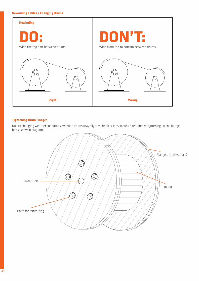
DO: DON’T:Wind the top part between drums. Wind from top to bottom between drums.
Rewinding
Right! Wrong!
Rewinding Cables / Changing Drums
Tightening Drum Flanges
Due to changing weather conditions, wooden drums may slightly shrink or loosen, which requires retightening on the flange bolts, show in diagram.
Center Hole
Bolts for reinforcing
Flanges. 2-ply (spruce)
Barrel
45

Proper Spooling Equipment
Although cables are generally tough, they can still be damaged by impact, pinching or abrasion. Pay-off spooling makes for an easy operation. Through faulty handling, cables may slide or ”crawl”. This can result in pinching or locking, which causes damage.
Pay-off spooling Equipment
46
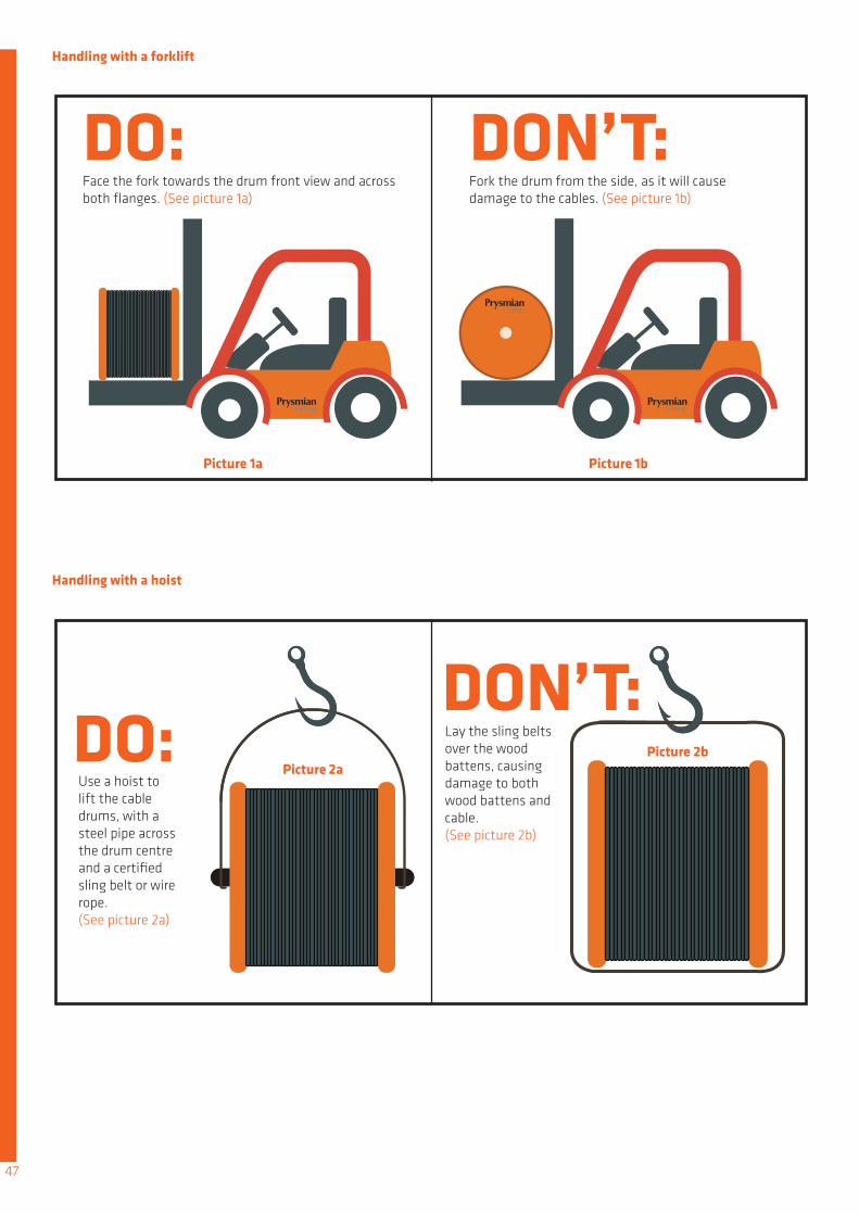
Handling with a forklift
Handling with a hoist
DO:
DO:
DON’T:
DON’T:
Face the fork towards the drum front view and across both flanges. (See picture 1a)
Use a hoist to lift the cable drums, with a steel pipe across the drum centre and a certified sling belt or wire rope. (See picture 2a)
Fork the drum from the side, as it will cause damage to the cables. (See picture 1b)
Lay the sling belts over the wood battens, causing damage to both wood battens and cable. (See picture 2b)
Picture 1a
Picture 2a
Picture 1b
Picture 2b
47

Storage
DO: DON’T:Cable drum in upright position, with 2 inch gap from crum flange edge (See picture 3a)
Cable drum laid on one flange side, causing cable sag. (See picture 3b)
1. Cables coiled in the drum must have a minimum 2 inch gap from the flange edge,2. For open storage, black PVC sheet must be used to wrap and protect the cables.3. Cable drums must be stored in an upright position.
4. Wood chokes should be placed under the flanges to prevent accidental rolling
5. In vertical storage, drum flanges must be aligned (Picture 4a). Misaligned flanges will come into contact with cables, causing damage. (Picture 4b)
Picture 3a
Picture 4a Picture 4b
Picture 3b
48

In March 2004, the Amendment No.2: AMD 14905 to BS7671: 2001 (IEE Wiring Rgulations Sixteenth Edition) has been harmonized with the CENELEC Standard HD 384.5.514: Identification including 514.3: Identification of conductor and with CENELEC Harmonization Document HD 308 S2: 2001 Identification of cores in cables and flexible cords.
The change in cable core colours is a major development that will affect the way wiring cable colours are distinguished and installed. Currently, for three phase fixed electrical installations, the wiring cable colours for “line” connections are red, yellow and blue respectively. The new three phase harmonized cable core colours will be brown, black and grey, following that of the new BS 7671: 2008 Requirements for electrical installations, IEE Wiring Regulations, 17th edition. A number of countries in the EuropeanUnion as well as Hong Kong and Singapore are implementing these harmonized cable core colours.
For any new electrical installation that involved extension from existing wiring system, BS7671 has been modified to align with these cable core colours where suitable marking/ labelling method eg. colour tapes, sleeves, discs, or by alphanumerics (letters and/or numbers) is allowed. See below figure:-
Existing
Existing
Label & Brown sleeve shall be provided at interface.
ExistingHarmonized
New
Harmonized
Identification of Cores in Cables
SINGLE-PHASE CIRCUITS THREE-PHASE CIRCUITS
LLNN
LLNN
L1L1
L2L2
L3L3NN
LNN
Cable cores colour code
Green / Yellow
Red
Red
Blue
Red
RedBlackBlackBlue
RedBlackBlue
L
L1
L3
L+
L+MML-
L+ML-
Cream
Black
Yellow
Black
Black
N
L2
N
L-
Green / Yellow
Brown
Brown
Grey
Brown
BrownBlueBlueGrey
BrownBlueGrey
Cream
Blue
Black
Blue
Grey
New Harmonized Core ColourExisting Core ColourFunction
Protective conductorFunctional earthing conductorAC Power Circuit
Three Phase Circuit
DC Two-Wire Unearthed Circuit
DC Two-Wire Earthed Circuit
DC Three-Wire Circuit
- Phase
- Phase 1- Phase 2- Phase 3- Neutral
- Positive- Negative
- Positive (of negative earth)- Negative (of negative earth)- Positive (of positive earth)- Negative (of positive earth)
- Positive- Mid-wire (may be earthed)- Negative
- Neutral
Alpha-numeric
Appendix G
49

THAILAND
7000 Units Housing DevelopmentBalai Bomba At Perumahan Kg Bt Beruang, TutongBalai Bomba Dan Perumahan Kampong MentiriBLNG / Refinery CCTVBLNG Cooling TowerBLNG Power PlantBrunei Methanol PlantBSP CER (Containerised Equipment Room)BSP DATA CentreBSP Magpie PlatformBSP Mampak PlatformBSP Seria North FlankBSP SuppliesBSP Tank Major RepairCentre Point Hotel updragingDES SuppliesDES SupplyEmpire Hotel upgradingKg Kilanas MosqueKiulap MallLight Industry Shop at Kg Katimahar, SengkurongMagistrate CourtMaraburong PrisonNaval BaseNew Building For Brunei Muara District Radio TV BruneiRTB (Radio TV Brunei)SCOT RejuvenisationShell Brunei RefineryTutong Street Lighting
PAJAM, SOLAR FARMPEMBINAAN PEJABAT TANAH & GALIAN PAHANGPetronas Refinery MelakaPetronas Twin TowersRAUB AUSTRALIAN GOLD MINE PROJECTS-COGENERATION ProjectSGL CARBON BANTINGShell offshore Platform B11, F6, F26SMART Tunnel ProjectSPMY - HK SL SUNPOWERSUBANG AVENUESUNPOWER PROJECT SITE (SPMY-HK 8L)Tawakai HospitalTeluk Salut, Ranhill PowerTenaga National Berhad SCADA SystemTNBTNB SCADA SystemUOA Holding Berhad - 2 Block Condominium at Bangsar SouthUTUSAN MALAYSIAWisma Lee RubberWISMA PERSEKUTUAN AT MITC MELAKAWTP
ALAM DAMAIBANK NEGARABank Negara Malaysia, CyberjayaBASF Gebeng, PetronasCAPITAL SQUARE KLCustoms KelantanCX5CYBERJAYA PRIMA 9 & 10CYGAL PROPERTIESGood Wood Hotel, JBGOOGLE DATA CENTERHONG LEONG DATA CENTERJaya Jusco, Bukit Indah, JBJB PROJECTKINRARA MAS PUCHONGKLIA 2 - MOV COMMUNICATIONKLIA SPUR LINEKuantan & Segamat CompressorExpansion ProjectLHDNM - CYBERJAYALight Rail Transit StationLOT C, KLCCLYNASExpansion ProjectLHDNM - CYBERJAYALight Rail Transit StationLOT C, KLCCLYNASMCOT PetronasMegasteelMELODY HOME PROJECTMEMCMidvalley MegamallMLNG – Fire & Gas System, Metering Station 1MyDin HypermarketPACIFIC FOODPAHLAWAN
Ca Mau PipelineBk Thien Ung Wellhead PlatformCan Tho AirportCat Bi AirportCat Bi International AirportCCP PlatformCo Chien BridgeDamen ShipyardDinh Co Gas Processing PlantDung Quat Oil RefineryDung Quat Refinery’s Sulfur Recovery Unit 2 (Sru2)Fideco Building, HCMCGemadept TowerHanoi MuseumHolcim PlantHRD PlatformHyatt HotelIndoChina Plaza HanoiLpg Dinh VuMDF FactoryMinistry of Defense Vietnam - Naval Base Power SupplyMSP6 PlatformNam Con Son Gas PipelinesNoi Bai Airport – Terminal 2Park Hyatt HCMRadio Frequency Office BuildingRMIT University HCMSaigon Pearl CondominiumTan Son Nhat International Airport – UpgradingTan Son Nhat Oil StorageThai Binh - Ham Rong Gas PipelinesThai Binh – Ham Rong Gas Distribution & Gathering SystemThi Vai LPG Storage Tanks DevelopmentVietcombank Tower HCMVietnam National Assembly HouseWhite Lion – Ehouse Stt
A’Posh BizhubAlstom Metropolis C830Anchor Handling Tug/Supply AHTS – Ice ClassBaywater Condo, TheBreadtalk HQCivil Aviation Authority of Singapore - Changi Airport T3Changi Airport GroupChangi Naval BaseChangi PMS Electrical WorksChangi Prison ComplexChangi Prison HQChangi Water Reclamation PlantCircle Line Stage 3 (Mechancial)Circle Line Stage 3,4,5 (Electrical)Circle Line C830, C414Common Service Tunnel - MarinaCreek CondoCredit Suisse Data CenterDBSS TampinesDBSS - YishunDeutsche Bank @ Mapletree Business CityDHL @ Greenwich Drive Tampines LogisparkDowntown line signal package, C955, C956, C960, C961Downtown Line Stage 1Downtown Line Stage 2Downtown Line Stage 3Exxon Mobile Singapore Parallel Trains 1 & 2, Jurong IslandFormula One - Singapore GPGardens by the BayHDB - Commercial, Industrial & Residential ProjectsION OrchardIslamic HubKallang Paya Lebar Expressway C415Management Development Institute of SingaporeMarina Coastal Expressway C461, C466Marina Bay Sands Integrated ResortMcDermott Deep Sea Pipe Laying VesselMermaid Marine Platform Supply VesselMSD Pharmaceutical FacilityNational Centre For Infectious DiseasesNational University HospitalNorth Point CityNorth South Line Extension (Electrical), C1565North South Line Extension (Mechanical), C1563North, South, East, West Re-signaling ProjectOkio CondominumOne Riverside DevelopmentOrchard GatewayOTS10 (Oil Tanking) ProjectOxley Bizhub 1 & 2Penjuru TerminalIstana CCTVPSA Corporation Harbor projectsRegal TheatreRenewable Energy ConsortiumRepublic of Singapore Navy Littoral Mission VesselsSavvis DatacenterSBM Shell Stones FPSOSchering Plough ExpansionSerangoon Nursing HomeSG2 Equinox DatacentreSingapore General Hospital Heart CenterSingapore General Hospital Pathology CenterShell Bukom C2 JettyShell Houdini, Bukom RefineryShell MEG Air Liquide ProjectSingapore Sports HubSt James Power StationTampines Town Hub BQThe Pier @ Robertson QuayThe Pinnacle Collection, Sentosa CoveThe Sail CondoTranshub Cold Hub 2Tuas DepotTuas Incineration PlantTuas Undersea TunnelTuas West ExtensionUE Bizhub East @ Changi Business Park
Vopak Horizon Project PII & PIIIWoodlands MRTYamal Substation and SKID supplyYen San Building, OrchardYishun HospitalYong Loo Lin School of MedicineZion Bishan Bible - Presbyterian Church
Airport Rail LinkBan Rachaprasong RachadomriBangchat Combine Heat & Power PlantBangkok Bank BuildingBangkok Metropolitan AdministrationBangkok Transit Systems (BTS)Bangsui WaterteastmentBaromchonranee Tunnel RoadBNCChulalongkorn UniversityExpressway Thailand AuthorityGlow Power 115 MW CFB#3Honda New Factory - 3Jasmine TelecomKLT - 8Love Beach HotalLP HospitalityMahidol University (Dentistry Department)ManeeyaMass Rapid Transit System (MTRA –Blue Line)MEA 230 KV Transmission TunnelMEA 230kV Underground Transmission Line Between Bangkapi and ChidlomMEA PM2-0030-WBA Modification Of 69 Kv CircuitBreaker 9 Substations.Novetel Airport HotelPre Clinic Siriraj HospitalPrin Narathiwas, Prin RatchaprarobPTT ESP & GSP#6 PlantPTT Phenol PlantPuric Latic Acid Refinery PlantRamkamkhang UniversityRicoh (RMT) New FactorySamart Ministry of Defense SouthernProvinces CCTVSCB Data CenterSiam Cement Group Chemicals _ THPP#3Suvanabhumi International Airport (SBIA)Thammasat University RangsitThappline – Ethanol & GasoholThe Room RadchadaTriple T Broadband ProjectTrue MultimediaUnited International Highway
Australia EmbassyBritish EmbassyCiputra WorldDATA Centre at SurabayaKemang Village AptKuningan CityLife Style Kuta BaliLOTTE Mart BintaroMall SummareconMayapada HospitalSILOAM HospitalST MoritzTANG City MallTEMPO ScanTRANS Studio Bandung
VIETNAM
BRUNEI
Linking ASEAN to Fire Safety - Our Footprint
MALAYSIA
SINGAPORE
INDONESIA
50
Linking fire safety to reliable connectivity
Certification Partners
ASEAN SALES OFFICES
Singapore Cables Manufacturers Pte Ltd (SCM) +65 6461 7800 [email protected]
MCI Draka Cable Co Ltd (MDC)+66 2308 0830 [email protected]
Draka (Malaysia) Sdn Bhd (DM)+603 7803 7171 [email protected]
Singapore Cables Manufacturers Pte Ltd, Rep Office (HCMC)+848 39260581 [email protected]
PT Prysmian Cables Indonesia (PCI)+62 21 [email protected]
For enquiries outside the above territories: [email protected] Print version: October 2017©Singapore Cable Manufacturers Pte Ltd (SCM). All contents are subjected to changes without prior notice.
Singapore
Thailand
Malaysia
Vietnam
Indonesia
asean.prysmiangroup.com