Embed Size (px)
Citation preview

Fire Hose and Appliances

Identify the Construction Features of Fire Hose
• Materials used in construction – Cotton – Nylon – Rayon vinyl – Poly-mired vinyl – Polyester

Identify the Construction Features of Fire Hose
• Construction methods – Braided
• Yarn braided over a rubber liner

Identify the Construction Features of Fire Hose
• Construction methods – Wrapped
• Fabric or mesh impregnated with rubber or plastic, wrapped around a rubber liner

Identify the Construction Features of Fire Hose
• Construction methods – Woven
• Rubber liner with one or more outer layers called a jacket
Identify the Construction Features of Fire Hose
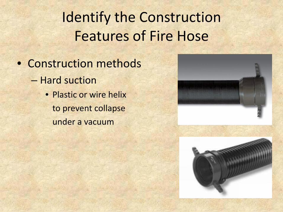
• Construction methods – Hard suction
• Plastic or wire helix to prevent collapse under a vacuum

Identify the Construction Features of Fire Hose Couplings
• Materials – Brass alloy – Aluminum alloy – Magnesium

Identify the Construction Features of Fire Hose Couplings
• Types
Threaded Storz
Oil field rocker lug
Quarter turn
Snap or Jones

Identify the Construction Features of Fire Hose Couplings
• Manufacturing techniques – Drop-forged
• Hardest • Hammering hot metal into dies
– Extruded • Somewhat weaker than drop-forged • Pushed or pulled through a die
– Cast • Weakest • Pouring liquid metal into a mold

Identify the Construction Features of Fire Hose Couplings
• Threaded – Three piece
• Combination of male and female ends
– Five piece • Same as three piece with addition of reducer or
adapter to both the male and female ends • Used to reduce size of hose or attach two hoses of
different threads

Identify the Construction Features of Fire Hose Couplings
• Threaded – Parts
• Shank – Tailpiece, bowl or shell – Male has lugs
• Swivel – Contains female threads – Permits coupling without turning hose – Has lugs

Identify the Construction Features of Fire Hose Couplings
• Threaded – Parts
• Higbee cut and indicator – On both couplings – Designed to provide the connection point of the threads – Indicator is a shallow indentation of one of the lugs

Identify the Construction Features of Fire Hose Couplings
• Threaded – Parts
• Lugs
Pin
Rocker
Recessed

Identify the Construction Features of Fire Hose Couplings
• Storz – Sexless
• No male or female
– Third turn to couple – Locking components
• Grooved lugs • Insert rings built into the swivel

Identify the Types and Sizes of Fire Hose
• Small diameter hose (SDH) – 3/4“ to 2” – Booster: 1” rubber covered – Forestry – Length: 50ft to 100ft

Identify the Types and Sizes of Fire Hose
• Medium diameter hose (MDH) – Woven or rubber jacket – 1 ½” to 3” – 50ft to 100ft

Identify the Types and Sizes of Fire Hose
• Large diameter hose (LDH) – Woven or rubber jacket – 3 ½” to 5” – 25ft to 50ft

Identify the Types and Sizes of Fire Hose
• Intake – Woven or rubber jacket – Hard and soft suction – 2 ½” to 6”

Identify the Procedure for Inspecting, Cleaning and Maintaining Fire Hose
• Washing hose – Lay the hose straight out – Brush off dust and dirt – Wash and scrub with clean water – Scrub spots with mild soap or detergent – Rinse properly and completely
• Drying hose – Hose tower – Place on inclined rack – Place in a cabinet hose dryer – Synthetic fibers do not need drying

Identify the Types and Prevention of Fire Hose Damage
Examples • Worn places • Rips • Abrasions • Cracked inner linings • Crushed or damaged couplings
Prevention • Avoid laying or pulling over sharp
corners • Provide warning devices in traffic
lanes • Prevent vehicles from running
over • Close nozzles slowly • Change positions of bends in hose
when reloading • Provide chafing blocks • Avoid excessive pump pressure
on hose lines
Mechanical damage

Identify the Types and Prevention of Fire Hose Damage
Examples • Charring • Melting • Drying of the rubber lining
Prevention • Protect hose from heat or fire • Do not allow hose to remain in heated
area after drying • Use moderate temperature for drying • Keep the outside jacket dry • Rotate hose in and out of service • Avoid drying hose on hot pavement • Prevent hose from coming in contact
with or close to vehicle exhaust • Use hose bed covers to shield hose
from sun
Thermal damage

Identify the Types and Prevention of Fire Hose Damage
Examples • Decay • Deterioration
Prevention • All wet hose should be removed
from the apparatus, replaced and dried
• Hose should be removed, inspected, swept and reloaded if not used every 30 days
• Exercise hose every 30 days • Run water through it every 90 days
Mildew and mold damage

Identify the Types and Prevention of Fire Hose Damage
Examples • Exposure to petroleum products • Exposure to run off • Exposure to acids / alkali’s
Prevention • Thoroughly scrub all traces of acid contacts
with baking soda and water • Periodically remove hose from the apparatus,
wash it, and run water through it • Properly test hose if any suspicion of damage • Avoid laying hose in the gutter • Properly dispose of hose that has been
exposed to hazardous materials and cannot be decontaminated
• Use caution when storing equipment in the same compartment as hose – leaking fluids can cause chemical damage to the hose
Chemical damage

Identify the Procedure for Inspecting, Cleaning and Maintaining Couplings
• Male – Check threads for damage or debris – File threads to remove burrs
• Female – Check threads for damage or debris – Remove gasket and twist in warm, soapy water – Check gasket for cracks, creases and elasticity

Identify the Procedure for Inspecting, Cleaning and Maintaining Couplings
• Replacing a gasket – Holds the gasket between your middle
finger and thumb with his/her index finger resting on the outside of the gasket
– Folds the outer rim of the gasket upward by pulling with his/her index finger
– Places the gasket into the swivel by permitting the large loop of the gasket to enter the coupling swivel at the place provided for the gasket
– Allows the small loop to fall into place by releasing his / her grip on the gasket

Identify the Types and Uses of Hose Rolls
• Straight – Placing hose into storage – Returning to quarters for washing – Loaded back on the apparatus

Identify the Types and Uses of Hose Rolls
• Donut – Situations when it is going to be deployed directly from a roll
for use – Used when both ends need to be together on the outside – Hose is less likely to spiral or kink when unrolled

Identify the Types and Uses of Hose Rolls
• Donut – method two

Identify the Types and Uses of Hose Rolls
• Twin donut – For a compact roll which may be transported and
used for high-rise or special operations

Identify the Types and Uses of Hose Rolls
• Self-locking twin donut – Same as twin donut, only a carrying strap is formed

Identify Forward and Reverse Lays
• Forward – From source to scene – Female coupling comes off first
• Reverse – From scene to source – Male coupling comes off first

Identify the Techniques of Coupling and Uncoupling Fire Hose
• Single firefighter foot tilt method

Identify the Techniques of Coupling and Uncoupling Fire Hose
• Single firefighter knee press method

Identify the Techniques of Coupling and Uncoupling Fire Hose
• Two firefighter coupling method

Identify the Techniques of Coupling and Uncoupling Fire Hose
• Two firefighter stiff arm method

Identify the Techniques of Moving Hoselines into Position
• Shoulder carry from a flat load

Identify the Techniques of Moving Hoselines into Position
• Shoulder carry from an accordian load

Identify the Techniques of Moving Hoselines into Position
• Hose drag

Identify the Techniques of Moving Hoselines into Position
• Hose drag / carry

Identify the Techniques of Moving Hoselines into Position
• Precautions – All firefighters on same side of hose – Check door, for heat, before opening / entering – Bleed off air and check pattern before entering – Stay low – Avoid blocking ventilation openings such as doors
and windows

Identify Types of Hose Loads
• Loading guidelines – Check the gaskets and swivel before connecting any coupling. – When two sections are connected, keep the flat sides of the
hose on the same plane – Hand tighten all connections – When the hose must be bent, smooth the inside of the bend. – Avoid loading hose so the coupling has to “turn”. Use a
“dutchman” to prevent it – For large diameter hose, load all couplings in the front of the
bed. – Do not pack the hose too tightly

Identify Types of Hose Loads
• Accordion

Identify Types of Hose Loads
• Horseshoe

Identify Types of Hose Loads
• Reverse horseshoe

Identify Types of Hose Loads
• Flat

Identify Types of Hose Loads
• Minuteman

Identify Types of Hose Loads
• Triple layer
Identify Types of Hose Loads
• Straight finish – Loosely flake the last two or three sections of hose
back and forth across the hose bed on top of the hose load.
– Attach any appliances or tools necessary to the hose

Identify the Purpose and Procedure of the Dutchman
• A short fold of hose or a reverse fold that is used allowing for coupling placement on the load – Changes the direction of the coupling – Changes the location of the coupling – Used when two couplings come to a point where a fold should take place – Use when two couplings end on top of each other

Identify the Function of a Hose Clamp
• To prevent charging a hose bed during a forward lay to a hydrant
• To allow replacement of a burst section of hose without shutting down the water supply
• To allow extension of a hose line without shutting down the water supply
• To allow advancement of a charged hoseline upstairs

Identify the Techniques for Lengthening and or Replacing a Hose
• Hose Clamp – Apply the clamp 3-5 feet behind couplings – Attach or replace section(s) of hose – Remove clamp
• Kink method – Form a loop in hoseline – Bend hose over itself – Apply body weight to bends in hose – Replace hose – Slowly release the pressure on the bend

Identify the Appliances and Tools Carried on a Pumper as Required by NFPA 1901
• Appliance – A device, other than a coupling, that is used with
hose and through which water must pass
• Tool
– A device that makes the handling of hose and appliances easier and or helps to protect hose against unnecessary wear and damage

Identify the Appliances and Tools Carried on a Pumper as Required by NFPA 1901
• Appliances – Valve
• Ball

Identify the Appliances and Tools Carried on a Pumper as Required by NFPA 1901
• Appliances – Valve
• Gate

Identify the Appliances and Tools Carried on a Pumper as Required by NFPA 1901
• Appliances – Valve
• Butterfly

Identify the Appliances and Tools Carried on a Pumper as Required by NFPA 1901
• Appliances – Valve
• Clapper

Identify the Appliances and Tools Carried on a Pumper as Required by NFPA 1901
• Appliances – Wye
• Divides one hoseline into two or more • Double gated reducing leader wye (required)
Identify the Appliances and Tools Carried on a Pumper as Required by NFPA 1901
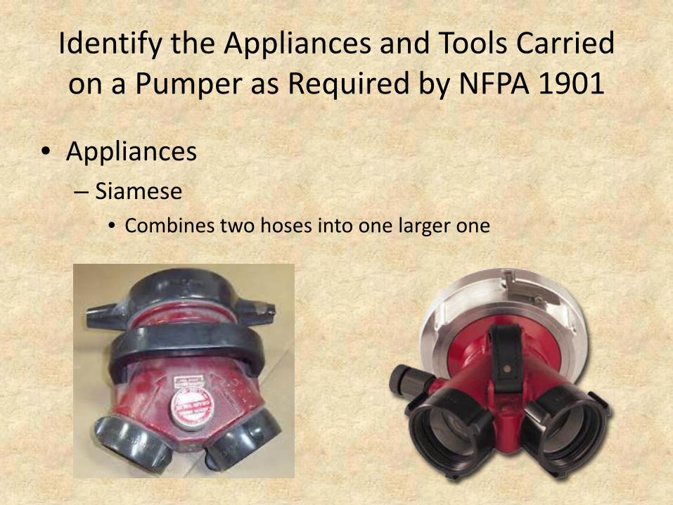
• Appliances – Siamese
• Combines two hoses into one larger one

Identify the Appliances and Tools Carried on a Pumper as Required by NFPA 1901
• Appliances – Water thief
• One inlet and one outlet of the same size plus multiple smaller outlets

Identify the Appliances and Tools Carried on a Pumper as Required by NFPA 1901
• Appliances – Hydrant valve (required)
• Allows an additional engine to connect to the hydrant without shutting the hydrant down

Identify the Appliances and Tools Carried on a Pumper as Required by NFPA 1901
• Appliances – Fittings
• Adapter – changes one type of hose thread to another • Reducer – connect a large hose to a smaller one • Double – male or female threads on both ends (required)

Identify the Appliances and Tools Carried on a Pumper as Required by NFPA 1901
• Appliances – Strainer
• Placed over the end of a suction to block debris

Identify the Appliances and Tools Carried on a Pumper as Required by NFPA 1901
• Appliances – Master stream device (required) – 350 gpm minimum

Identify the Appliances and Tools Carried on a Pumper as Required by NFPA 1901
• Appliances – Foam delivery equipment (required)

Identify the Appliances and Tools Carried on a Pumper as Required by NFPA 1901
• Tools

Identify the Appliances and Tools Carried on a Pumper as Required by NFPA 1901
• Tools

Identify the Techniques for Advancing an Uncharged Attack Line from a Pumper
CAUTION: An uncharged hoseline should never be advanced into a fire or through a door that is hot to touch. The line should be charged and the nozzle person should open the nozzle, bleed the air off, and select the proper pattern before entering the fire area

Identify the Techniques for Advancing an Uncharged Attack Line from a Pumper
• Into a structure – Select a hoseline, properly remove it from the apparatus and
deploy it toward the entrance – The nozzle person and back up firefighters are on the same
side of the hoseline – The nozzle person is at the nozzle and the officer or second
firefighter is a few feet back; if available, the next firefighter is approximately at mid-point of the first section and the coupling
– Feel the door for heat. This can give an indication of extreme heat buildup, signifying the potential for a backdraft or flashover
– Stay low and avoid blocking ventilation openings such as doorways or stairs
Identify the Techniques for Advancing an Uncharged Attack Line from a Pumper
• Up a ladder to a second floor landing (Caution: Charged hoselines should only be advanced up a
ladder when absolutely necessary.) – The hoseline is brought to the base of the ladder where it is
charged and the nozzle is bled – The nozzle person and the firefighters space themselves on the
ladder within reach of each other – Each firefighter ties into the ladder with a leg lock or ladder belt. – Using both hands, the hoseline is pushed upward from firefighter
to firefighter – The nozzle person advances the line into the second floor landing. – The other firefighters continue to hoist additional hose as
necessary

Identify the Techniques for Advancing an Uncharged Attack Line from a Pumper
• Up a stairway to an upper floor – Select a hoseline, properly remove it from the apparatus, and
deploy it to the base of the inside stairway – When the hoseline is in place, the nozzle person has the line
charged, bleeds the nozzle, and prepares to advance the line. – Advance the hose laying it on the stairs against the outside
wall to avoid sharp kinks and bends – If possible, firefighters should be placed at every turn or
point of resistance to assist in deployment – Once desired landing is reached, the excess hose can be
advanced up the stairs toward the floor above the fire and looped back down.
– Entry is then made into the fire floor of the fire area

Identify the Techniques for Advancing an Uncharged Attack Line from a Pumper
• Down a stairway to a lower floor – Select a hoseline, properly remove it from the apparatus and
deploy it to the inside stairway – When the hoseline is in place, the nozzle person has the line
charged, nozzle and prepares to advance the line – Advance the hose, laying it on the stairs against the outside
wall to avoid sharp kinks and bends – If possible, firefighters should be placed at every turn or
point of resistance to assist in deployment – Once the desired landing is reached, it is necessary to have
all available hose on the fire floor – Entry is then quickly made in the fire floor or fire area. – Expect to encounter heavy heat conditions while advancing
lines down inside stairways

Identify the Technique for Operating a Charged Attack Line from a Ladder
(Caution: Operating a hoseline from a ground ladder requires the ladder to be securely tied in and heeled)
• The ladder is secured • The hoseline is brought to the base of the ladder where the line is charged
and the nozzle is bled • The nozzle person and firefighters space themselves on the ladder within
reach of each other • Each firefighter ties into the ladder with a leg lock or ladder belt • Using both hands, the hoseline is then pushed upward from firefighter to
firefighter • The nozzle person projects the nozzle through the ladder rungs allowing
approximately one (1) foot to be extended beyond the rungs at the appropriate level, and secures the hose with a ladder belt or rope hose tool
• Secure the hose with a ladder belt or rope hose tool several rungs below the one the nozzle person is standing on
• Once the hoseline, nozzle, and all firefighters are tied in and secured, with the ladder heeled, the nozzle may be opened slowly

Identify the Technique of Carrying a Hoseline into a Building, Connecting it to a Standpipe and Advancing the Line from
the Standpipe
• Carry the appropriate 100 feet of a minimum of 1½ inch hoseline to one floor below the fire floor
• Detach the building hoseline or remove the outlet cap • Check the connection for adapters (if needed) and foreign objects in
the discharge • Connect the fire department hose to the standpipe connection. It is a
good practice to connect a gated wye to the connection before the attack line is connected
• Advance the hoseline up to the fire floor; any extra hose could be flaked up the stairs toward the floor above the fire floor
• When firefighters are in position to effect the attack, the line is charged and the nozzle is bled
• Check the door with the back of an ungloved hand. If appropriate, open the door slowly and advance the line toward the fire

Identify the proper technique of connecting hoseline(s) from a piece of fire apparatus, to
a Fire Department Connection (FDC)
• Remove intake hose(s), hydrant wrench and other required tools from the pumper
• Unroll the hose • Connect the hose(s) to the pumper • Remove the appropriate FDC cap(s) or break open only
the needed caps with a spanner • Connect the hose(s) to the FDC, using any adapters
necessary • Operate pump at required pressure • Tighten any connection(s) that leak