Embed Size (px)
Citation preview
BRITISH STANDARD
BS 5306-4:2001Fire extinguishing installations and equipment on premises —
Part 4: Specification for carbon dioxide systems
ICS 13.220.20
NO COPYING WITHOUT BSI PERMISSION EXCEPT AS PERMITTED BY COPYRIGHT LAW
BS 5306-4:2001
This British Standard, having been prepared under the direction of the Health and Environment Sector Committee, was published under the authority of the Standards Committee and comes into effect on15 August 2001
© BSI 07-2001First published October 1979 Second edition March 1986 Third edition August 2001
The following BSI references relate to the work on this standard:Committee reference FSH/18Draft for comment 00/541249 DC
ISBN 0 580 37963 9
Committees responsible for this British Standard
The preparation of this British Standard was entrusted to Technical Committee FSH/18, upon which the following bodies were represented:
British Fire Protection Systems Association
Chief and Assistant Chief Fire Officers Association
Health and Safety Executive
Home Office
Institute of Fire Safety
Institution of Fire Engineers
London Fire and Civil Defence Authority
Loss Prevention Council
Maritime and Coastguard Agency
Ministry of Defence
Society of Motor Manufacturers and Traders
Warrington Fire Research Centre
Amendments issued since publication
Amd. No. Date Comments
BS 5306-4:2001
© BSI 07-2001
Contents
PageForeword iiiIntroduction 1
1 Scope 12 Normative references 13 Terms and definitions 34 Characteristics and uses of carbon dioxide 55 Types of system 56 Planning 67 Working documents 68 Commissioning and acceptance 79 Inspection, maintenance, testing and training 1010 Total flooding systems 1111 Local application systems 2112 Manual hose systems 2613 System components 2714 System operation 2815 Safety precautions 2916 Carbon dioxide supply 3317 Quantity of carbon dioxide 3418 Storage containers 3419 Pipework 3620 Installation of pipework 4021 Marking of pipework 43
Annex A (normative) Door fan test for determination of minimum hold time 44Annex B (informative) Service schedule 50Annex C (normative) Determination of carbon dioxide concentrations for flammable liquids and gases 51Annex D (informative) Examples of calculation of carbon dioxide requirements 56Annex E (informative) Determination of carbon dioxide pipe and orifice size 57
Bibliography 69
Figure 1 — Calculated CO2 loss rate based on an assumed 21 ºC temperature within the enclosure and 21 ºC ambient outside 14Figure 2 — Aiming position for angled discharge nozzles 26Figure 3 — Label to be displayed at manual control 32Figure 4 — Label to be displayed at entrances to hazard 33Figure C.1 — Cup burner apparatus 55Figure E.1 — Pressure drop in pipeline for 20.7 bar storage pressure 61Figure E.2 — Pressure drop in pipeline for 51.7 bar storage pressure 62
Table 1 — Volume factors 16Table 2 — Minimum carbon dioxide concentration for extinction 17Table 3 — Hazard factors 18Table 4 — Extended discharge gas quantities for enclosed recirculation: rotating electrical machines 20Table 5 — Aiming factors for nozzles installed at an angle (based on 150 mm freeboard) 26Table 6 — Safety precautions for total flooding systems 29
i
BS 5306-4:2001
ii
PageTable 7 — Carbon dioxide requirements 34Table 8 — Monitoring facilities 35Table 9 — Closed sections of pipework 37Table 10 — Open-ended pipework 38Table 11 — Pipe fittings for closed and open ended pipework section — High pressure systems 39Table 12 — Pipe fittings for closed and open ended pipework section — Low pressure systems 39Table 13 — Maximum pipework support spacings 41Table 14 — Safety clearances to enable operation, inspection, cleaning, repairs, painting and maintenance work to be carried out 43Table E.1 — Values of Y and Z 58Table E.2 — Values of Y and Z for 51.7 bar storage 59Table E.3 — Discharge rate of equivalent orifice area for low pressure storage (20.7 bar) 64Table E.4 — Equivalent length of threaded pipe fittings 64Table E.5 — Equivalent length of welded pipe fittings 65Table E.6 — Elevation correction factors for low pressure systems 65Table E.7 — Elevation correction factors for high pressure systems 65Table E.8 — Discharge rate of equivalent orifice area for high pressure storage (51.7 bar) 66Table E.9 — Equivalent orifice sizes 67
© BSI 07-2001
BS 5306-4:2001
© BSI 07-2001
Foreword
This part of BS 5306 has been prepared by Technical Committee FSH/18. It supersedes BS 5306-4:1986, which is withdrawn.
The other parts of BS 5306 are as follows:
— Part 0: Guide for the selection of installed systems and other fire equipment;— Part 1: Hydrant systems, hose reels and foam inlets;— Part 2: Specification for sprinkler systems;— Part 3: Maintenance of portable fire extinguishers — Code of practice;— Part 5: Halon systems
— Section 5.1: Specification for halon 1301 total flooding systems;— Section 5.2: Halon 1211 total flooding systems;
— Part 6: Foam systems— Section 6.1: Specification for low expansion foam systems;— Section 6.2: Specification for medium and high expansion foam systems;
— Part 7: Specification for powder systems;— Part 8: Selection and installation of portable fire extinguishers — Code of practice.
As several different methods of piping supplies of carbon dioxide and applying the gas at the required points of discharge for fire extinction have been developed in recent years, there is a need for dissemination of information on established systems and methods. This standard has been prepared to meet this need. Its requirements and recommendations are made in the light of the best technical data known to the committee at the time of writing, but since a wide field is covered it has been impracticable to consider every possible factor or circumstance that might affect implementation of the requirements and recommendations.
It has been assumed in the preparation of this standard that the execution of its provisions is entrusted to appropriately qualified and experienced people.
Annex A and Annex C are normative. Annex B, Annex D and Annex E are informative.
A British Standard does not purport to include all necessary provisions of a contract. Users of British Standards are responsible for their correct application.
Compliance with a British Standard does not of itself confer immunity from legal obligations.
Summary of pagesThis document comprises a front cover, an inside front cover, pages i to iv, pages 1 to 69 and a back cover.
The BSI copyright notice displayed in this document indicates when the document was last issued.
iii

iv blank
BS 5306-4:2001
Introduction
It is important that the fire protection of a building or plant is considered as a whole. Carbon dioxide (CO2) systems form only a part, though an important part, of the available facilities, but it should not be assumed that their adoption necessarily removes the need to consider supplementary measures, such as the provision of portable fire extinguishers or other mobile appliances for first aid or emergency use or to deal with special hazards.
CO2 has for many years been a recognized effective medium for the extinction of flammable liquid fires and fires in the presence of electrical and ordinary class A hazards, but it should not be forgotten, in the planning of comprehensive schemes, that there may be hazards for which these mediums are not suitable, or that in certain circumstances or situations there may be dangers in their use, requiring special precautions.
Advice on these matters can be obtained from the appropriate fire authority, the Health and Safety Executive or other enforcing authority under the Health and Safety at Work etc. Act 1974 [1], and insurers. In addition, reference should be made as necessary to other parts of BS 5306.
It is essential that fire extinguishing equipment is carefully maintained to ensure instant readiness when required. This routine is liable to be overlooked or given insufficient attention by supervisors. It is, however, neglected at peril to the lives of occupants of the premises and at the risk of crippling financial loss. The importance of maintenance cannot be too highly emphasized.
1 Scope
This part of BS 5306 specifies requirements and gives recommendations for the provision of carbon dioxide fire extinguishing systems in buildings or industrial plant. These systems are designed to convey carbon dioxide from a central source on the premises as and when required for the extinction of fire or the protection of particular plant or parts of the premises against possible fire risk.
This part of BS 5306 does not apply to carbon dioxide portable fire extinguishers or to wheeled appliances for conveying carbon dioxide in containers.NOTE 1 Requirements and recommendations for carbon dioxide portable fire extinguishers (together with portable fire extinguishers of other types) are given in BS EN 3-1 to -5 and BS 5306-3.
This standard gives requirements and characteristic data for carbon dioxide, the types of fires for which it is a recommended extinguishing medium, and requirements and recommendations for three established types of piped system embodying different concepts and employing different methods for the application of carbon dioxide, i.e.:
a) the total flooding system;
b) the local application system; and
c) the manual hose reel system.
Two methods of operation, i.e. manual and automatic, are also specified. Requirements and recommendations are given on the selection of a system, on operational methods, and on the design, maintenance and efficient operation of installations. Reference is also made to the part that carbon dioxide systems plays in general schemes of fire protection of premises, having regard to safety as well as efficiency.NOTE 2 Unless otherwise stated in the text all pressures are in bar gauge.
1 bar = 105 N/m2 = 100 kPa.
2 Normative referencesThe following normative documents contain provisions which, through reference in this text, constitute provisions of this part of this British Standard. For dated references, subsequent amendments to, or revisions of, any of these publications do not apply. For undated references, the latest edition of the publication referred to applies.
BS 21, Specification for pipe threads for tubes and fittings where pressure-tight joints are made on the threads (metric dimensions).
BS 381C:1996, Specification for colours for identification, coding and special purposes.
BS 476-4, Fire tests on building materials and structures — Part 4: Non-combustibility test for materials.
© BSI 07-2001 1
BS 5306-4:2001
BS 476-20, Fire tests on building materials and structures — Part 20: Method for determination of the fire resistance of elements of construction (general principles).
BS 476-21, Fire tests on building materials and structures — Part 21: Methods for determination of the fire resistance of loadbearing elements of construction.
BS 476-22, Fire tests on building materials and structures — Part 22: Methods for determination of the fire resistance of non-loadbearing elements of construction.
BS 476-23, Fire tests on building materials and structures — Part 23: Methods for determination of the contribution of components to the fire resistance of a structure.
BS 1387, Specification for screwed and socketed steel tubes and tubulars and for plain end steel tubes suitable for welding or for screwing to BS 21 pipe threads.
BS 1640-3:1968, Specification for steel butt-welding pipe fittings for the petroleum industry — Part 3: Wrought carbon and ferritic alloy steel fittings — Metric units.
BS 1710, Specification for identification of pipelines and services.
BS 1821, Specification for class I oxy-acetylene welding of ferritic steel pipework for carrying fluids.
BS 2051-1, Tube and pipe fittings for engineering purposes — Part 1: Copper and copper alloys capillary and compression tube fittings for engineering purposes.
BS 2051-2, Tube and pipe fittings for engineering purposes — Part 2: Specification for olive type copper alloy compression tube fittings.
BS 2633, Specification for Class I arc welding of ferritic steel pipework for carrying fluids.
BS 2915, Specification for bursting discs and bursting disc devices.
BS 3410, Specification for metal washers for general engineering purposes.
BS 3601, Specification for carbon steel pipes and tubes with specified room temperature properties for pressure purposes.
BS 3602-1, Steel pipes and tubes for pressure purposes: carbon and carbon manganese steel with specified elevated temperature properties — Part 1: Specification for seamless and electric resistance welded including induction welded tubes.
BS 3605-2, Austenitic stainless steel pipes and tubes for pressure purposes — Part 2: Specification for longitudinally welded tubes.
BS 3799:1974, Specification for steel pipe fittings, screwed and socket-welding for the petroleum industry.
BS 4320, Specification for metal washers for general engineering purposes — Metric series.
BS 4368-1, Compression couplings for tubes — Part 1: Split collet compression fittings.
BS 4422-4, Glossary of terms associated with fire — Part 4: Fire extinguishing equipment.
BS 4677, Specification for arc welding of austenitic stainless steel pipework for carrying fluids.
BS 4800:1989, Schedule of paint colours for building purposes.
BS 5355, Specification for filling ratios and developed pressures for liquefiable and permanent gases.
BS 5430-1, Periodic inspection, testing and maintenance of transportable gas containers (excluding dissolved acetylene containers) — Part 1: Specification for seamless steel containers of water capacity 0.5 litres and above.
BS 5839-1, Fire detection and alarm systems for buildings — Part 1: Code of practice for system design, installation and servicing
BS 6266, Code of practice for fire protection for electronic data processing installations.
BS 7273-1, Code of practice for the operation of fire protection measures — Part 1: Electrical actuation of gaseous total flooding extinguishing systems.
BS 7273-2, Code of practice for the operation of fire protection measures — Part 2: Mechanical actuation of gaseous total flooding and local application extinguishing systems.
BS 7671, Requirements for electrical installations — IEE Wiring Regulations — Sixteenth edition.
2 © BSI 07-2001
BS 5306-4:2001
BS EN 856, Rubber hoses and hose assemblies — Rubber-covered spiral wire reinforced hydraulic type — Specification.
BS EN 1057, Copper and copper alloys — Seamless, round copper tubes for water and gas in sanitary and heating applications.
BS EN 1515-1, Flanges and their joints — Bolting — Part 1: Selection of bolting.
BS EN 1435, Non-destructive examination of welds — Radiographic examination of welded joints.
BS EN 1964-1, Transportable gas cylinders — Specification for the design and construction of refillable transportable seamless steel gas cylinders of water capacities from 0,5 litre up to and including 150 litres — Part 1: Cylinders made of seamless steel with an Rm value of less than 1 100 MPa.
BS EN 1964-3, Transportable gas cylinders — Specification for the design and construction of refillable transportable seamless steel gas cylinders of water capacities from 0,5 litre up to and including 150 litres — Part 3: Cylinders made of seamless stainless steel with an Rm value of less than 1 100 MPa.
BS EN 10241:2000, Steel threaded pipe fittings.
BS EN 10242:1995, Threaded pipe fittings in malleable cast iron.
BS EN 12094 (all parts), Fixed firefighting systems — Components for gas extinguishing systems.
BS EN 12094-8, Fixed firefighting systems — Components for gas extinguishing systems — Part 8: Requirements and test methods for flexible connectors for CO2 systems.
BS EN 12449, Copper and copper alloys — Seamless, round tubes for general purposes.
BS EN 25923, Fire extinguishing media — Carbon dioxide (ISO 5923).
PD 5500, Specification for unfired fusion welded pressure vessels.
PD 6550 (all parts), Explanatory supplement to BS 5500:1988 — Specification for unfired fusion welded pressure vessels — Section three — Design.
ANSI B16.5:1996, Steel pipe flanges and flanged fittings.
ANSI B16.9:1993, Factory-made wrought steel buttwelding fittings.
ANSI B16.11:1997, Forged steel fittings, socket-welding and threaded.
API 5B, Specification for threading, gauging and thread inspection of casing, tubing and line pipe threads.
API 5L, Specification for line pipe.
ASTM A105M, Specification for carbon steel forgings for piping applications.
ASTM A106-77, Specification for seamless carbon steel pipe for high temperature service.
ASTM A234/A234M, Specification for piping fittings of wrought carbon steel and alloy steel for moderate and high temperature service.
3 Terms and definitions
For the purposes of this part of BS 5306, the terms and definitions given in BS 4422-4 and the following apply.
3.1 authorityorganization, office or individual responsible for approving equipment, installations or procedures
3.2 automatic operationmethod of operation in which a fire extinguishing system, under specified conditions, functions without intervention by a human operator
3.3 automatic/manual to manual only changeover switchmeans of converting a fire extinguishing system from automatic/manual to manual only actuation or vice versa NOTE This may be in the form of a manual switch on the control panel or other units, or a personnel door interlock.
© BSI 07-2001 3
BS 5306-4:2001
3.4 closed section of pipeworksection between two valves which may be intentionally or unintentionally closed, or between valves and carbon dioxide storage containers including filling and gas balance lines
3.5 competent personperson capable of carrying out the inspection and maintenance procedures of clause 9, by reason of experience and access to the requisite information, training, tools and equipment
3.6 deep-seated firefire involving solids subject to smouldering
3.7 filling densitymass of extinguishant per unit volume of container
3.8 high pressure storagestorage of carbon dioxide at ambient temperature, nominally 58 bar at 20 ºC
3.9 local application systemautomatic or manual fire extinguishing system in which a fixed supply of carbon dioxide is permanently connected to fixed piping with nozzles arranged to discharge the carbon dioxide directly to a fire occurring in a defined area that has no enclosure surrounding it, or is only partially enclosed, and that does not produce an extinguishing concentration throughout the entire volume containing the protected hazard
3.10 low pressure storagestorage of carbon dioxide in pressure containers at a controlled low temperature of –18 ºCNOTE The pressure in this type of storage is approximately 21 bar.
3.11 manual operation method of operation in which a fire extinguishing system, under specified conditions, functions by means of intervention of a human operator
3.12 manual hose reel systemmanual fire extinguishing system consisting of a hose, stowed on a reel or a rack, with a manually operated discharge nozzle assembly, all connected by a fixed pipe to a supply of carbon dioxide
3.13 material conversion factor (MCF)numerical factor used when the minimum design concentration of carbon dioxide for the material at risk exceeds 34 %, to increase the basic quantity of carbon dioxide [as obtained by application of the volume factor (see 3.19)] required for protection against surface fires
3.14 open-ended pipeworkpipework between a valve (including a relief valve) and open nozzles which cannot be under a continuous pressure
3.15 pilot containercontainer whose contents are only used for system actuation and whose contents do not form part of the quantity of extinguishant required
4 © BSI 07-2001
BS 5306-4:2001
3.16 surface firefire involving flammable liquids, gases or solids not subject to smouldering
3.17 total flooding systemautomatic or manual fire extinguishing system in which a fixed supply of carbon dioxide is permanently connected to fixed piping with nozzles arranged to discharge the carbon dioxide into an enclosed space in order to produce a concentration sufficient to extinguish fire throughout the entire volume of the enclosed space
3.18 userperson(s) responsible for or having effective control over the fire safety provisions adopted in or appropriate to the premises or the building
3.19 volume factornumerical factor that, when applied to the volume of an enclosure, indicates the basic quantity of carbon dioxide (subject to a minimum appropriate to the volume of the enclosure) required for protection against surface fires
4 Characteristics and uses of carbon dioxide
4.1 General
Carbon dioxide for use in fire extinguishing systems shall conform to BS EN 25923.
COMMENTARY AND RECOMMENDATIONS ON 4.1. Carbon dioxide at atmospheric pressure is a colourless, odourless and electrically non-conducting inert gas which is almost 1.5 times as dense as air. It is stored as a liquid under pressure, and 1 kg of liquid carbon dioxide expanded to atmospheric pressure will produce about 0.52 m3 of free gas at a temperature of 10 °C.
Carbon dioxide extinguishes fire by reducing the oxygen content of the atmosphere to a point where it will not support combustion. Reducing the oxygen content from the normal 21 % in air to 15 % will extinguish most surface fires, though for some materials a greater reduction is necessary. In some applications the cooling effect of carbon dioxide will assist extinction.
Carbon dioxide may be used to fight fires of classes A and B as defined in BS EN 2. Class C fires may also be extinguished by carbon dioxide but in these cases the risk of explosion after extinction should be carefully considered.
Carbon dioxide may be ineffective on fires involving material such as metal hydrides, reactive metals such as sodium, potassium, magnesium, titanium and zirconium, and chemicals containing oxygen available for combustion, such as cellulose nitrate.
Carbon dioxide is suitable for use on fires involving live electrical apparatus.
4.2 Electrostatic discharge
Carbon dioxide systems shall not be designed, installed or recommended for inerting explosive atmospheres. Carbon dioxide systems shall not be test discharged into areas containing explosive atmospheres.
COMMENTARY AND RECOMMENDATIONS ON 4.2. The discharge of carbon dioxide is known to produce electrostatic charges which, under certain conditions, could create a spark.
5 Types of systemCO2 systems shall conform to the requirements of one of the following types:
a) total flooding system;
b) local application system;
c) manual hose reel system.
© BSI 07-2001 5
BS 5306-4:2001
COMMENTARY AND RECOMMENDATIONS ON CLAUSE 5. In the selection of the type of carbon dioxide extinguishing system account should be taken of:
a) the degree of hazard to personnel arising from the CO2 discharge;
b) the nature of the hazard;
c) the location and degree of enclosure of the hazard;
d) operating requirements dictating either manual or automatic operation;
e) other factors discussed in clauses 10, 11 and 12.
6 PlanningWhere a fixed carbon dioxide extinguishing system is being considered for new or existing buildings the appropriate authority shall be consulted.
Where a fire detection and control system is used in conjunction with a CO2 system it shall conform to the requirements of BS 5839-1, BS 6266 and BS 7273-1 and -2 where appropriate.
COMMENTARY AND RECOMMENDATIONS ON CLAUSE 6. The appropriate authority should be informed as early as possible of the type of carbon dioxide system to be installed and the system design engineers should be fully informed of the protection required in any area, whether total flooding, local application or hose reel. There may be other requirements of the authority which should be incorporated into the planning stages of the contract.
7 Working documents
7.1 General
Working documents shall be prepared only by persons fully experienced in the design of fire extinguishing systems.
Deviation from working documents shall require the permission of the appropriate authority.
7.2 Requirements
Working documents shall include the following items:
a) drawings, to an indicated scale, of extinguishant distribution system including containers, location of containers, piping and nozzles, any valves and pressure reducing devices, and pipe hanger spacing;
b) name of owner and occupant;
c) location of building in which hazard is located;
d) location and construction of protected enclosure walls and partitions;
e) enclosure cross-section, full height or schematic diagram, including raised access floor and suspended ceiling;
f) type of extinguishant being used;
g) extinguishing or inerting concentration, design concentration and maximum concentration;
h) description of occupancies and hazards being protected;
i) specification of containers used, including capacity, storage pressure and mass including extinguishant;
j) description of nozzle(s) used including inlet size, orifice port configuration, and orifice size/code;
k) description of pipe valves and fittings used including material specifications, grade, and pressure rating;
l) equipment schedule or bill of materials for each piece of equipment or device showing device name, manufacturer, model or part number, quantity and description;
m) isometric view of extinguishant distribution system showing the length and diameter of each pipe segment and node reference numbers relating to the flow calculations;
n) enclosure pressurization and venting calculations (total flooding systems only);
o) description of fire detection, actuation and control systems.
6 © BSI 07-2001
BS 5306-4:2001
8 Commissioning and acceptance
8.1 Tests
8.1.1 General
The completed CO2 system shall be reviewed and tested by qualified personnel to meet the approval of the appropriate authority. To determine that the system has been properly installed and will function as specified, the tests specified in this clause (8.1.2, 8.1.3, 8.1.4, 8.1.5, 8.1.6, 8.1.7, 8.1.8, 8.1.9 and 8.1.10) shall be performed.
8.1.2 Enclosure check
It shall be determined that the hazard is in conformance with the drawings.
8.1.3 Review of mechanical components
8.1.3.1 The piping distribution system shall be inspected to determine that it conforms to the design and installation documents.
8.1.3.2 Nozzles and pipe size shall be in accordance with system drawings.
8.1.3.3 Piping joints, discharge nozzles, and piping supports shall be securely fastened to prevent unacceptable vertical or lateral movement during discharge. Discharge nozzles shall be installed so that piping cannot become detached during discharge.
8.1.3.4 During assembly, the piping distribution system shall be inspected internally to detect the possibility of any oil or particulate matter liable to soil the hazard area or affect the extinguishant distribution due to a reduction in the effective nozzle orifice area.
8.1.3.5 The discharge nozzles shall be oriented so that optimum extinguishant dispersal can be effected.
8.1.3.6 If nozzle deflectors are installed, they shall be positioned to obtain maximum benefit.
8.1.3.7 The discharge nozzles, piping, and mounting brackets shall be installed so that they will not potentially cause injury to personnel. Extinguishant shall not directly impinge on areas where personnel may be found in the normal work area, or on any loose objects or shelves, cabinet tops, or similar surfaces where loose objects could be present and become missiles.
8.1.3.8 All carbon dioxide storage containers shall be properly located in accordance with an approved set of system drawings.
8.1.3.9 All containers and mounting brackets shall be securely fastened in accordance with the manufacturer’s requirements.
8.1.3.10 Although a full carbon dioxide discharge test is not required for compliance with this standard, if a discharge test is to be conducted, the mass of extinguishant shall be determined by weighing or other approved methods.
COMMENTARY AND RECOMMENDATIONS ON CLAUSE 8.1.3.10. For total flooding systems discharge test concentration measurements should be made at a minimum of three points, one at the highest hazard level.
For local application systems a check shall be made that carbon dioxide effectively covers the hazard for the full period of time required by the design.NOTE For total flooding systems other assessment methods can normally be used to reduce unnecessary discharges into the environment, for example, the door fan pressurization test specified in Annex A. However, a discharge test may be conducted if required by the authority.
8.1.3.11 An adequate quantity of carbon dioxide to satisfy the design requirement shall be provided. For total flooding systems the actual enclosure volumes shall be checked against those indicated on the system drawings to ensure the proper quantity of extinguishant. Fan rundown and damper closure time shall be taken into consideration.
© BSI 07-2001 7
BS 5306-4:2001
8.1.3.12 Unless the total piping contains no more than one change in direction fitting between the storage container and the discharge nozzle, and where all piping is physically checked for tightness, the following tests shall be carried out.
a) All open ended piping shall be pneumatically tested in a closed circuit for a period of 10 min at 3 bar. At the end of 10 min, the pressure drop shall not exceed 20 % of the test pressure. NOTE 1 Pressure testing is not required where the piping has been physically checked for tightness and there is no more than one change in direction between the container and the nozzle.
b) All closed sections of pipework shall be hydrostatically tested to a minimum of 190 bar for high pressure systems and 36 bar for low pressure systems. At the end of 2 min there shall be no leakage. On completion of the test, the tested sections shall be purged to remove moisture.NOTE 2 It is recommended that hydrostatic testing is carried out at the manufacturer’s works.
NOTE 3 Pressure testing is not required where the piping between the manifold and a valve has been physically checked for tightness and there is no more than one change in direction between the manifold and the valve.
CAUTION Pneumatic pressure testing creates a potential risk of injury to personnel in the area, as a result of airborne projectiles if rupture of the piping system occurs. Prior to conducting the pneumatic pressure test, the protected area shall be evacuated and appropriate safeguards shall be provided for test personnel.
8.1.3.13 A test using nitrogen, or suitable alternative, shall be performed on the piping network to verify that flow is continuous and that the piping and nozzles are unobstructed.
8.1.3.14 Fusible link systems shall be tested to ensure that control cable lines are free and that operating control weights develop sufficient energy to operate container and/or direction valve control mechanisms.
8.1.3.15 Pneumatic detection systems shall be tested with a manometer to ensure correct breathing rate and leak free capillary lines.
8.1.3.16 Nameplates and instruction plates shall be checked to ensure they are correctly worded.
8.1.3.17 Detectors shall be activated in accordance with the manufacturer’s instructions to ensure correct operation and subsequent activation of control mechanisms.
8.1.4 Review of enclosure integrity
All total flooding systems shall have the enclosure checked to locate and then effectively seal any significant air leaks that could result in a failure of the enclosure to hold the specified extinguishant concentration level for the specified holding period (see also 10.4.1 and 10.5). Unless otherwise required by the appropriate authority, the test specified in Annex A shall be used.
8.1.5 Review of electrical components
8.1.5.1 All wiring systems shall be properly installed in accordance with BS 7671 (IEE Wiring Regulations) and the system drawings. A.c. and d.c. wiring shall not be combined in a common conduit unless properly shielded and grounded.
8.1.5.2 All field circuitry shall be measured for ground fault and short circuit condition. When measuring field circuitry, all electronic components (such as detectors or special electronic equipment for other detectors or their mounting bases) shall be removed and jumpers properly installed to prevent the possibility of damage within these devices. Components shall be re-instated after measuring.
8.1.5.3 Adequate and reliable primary standby sources of energy, which conform to the requirements of 8.1.9, shall be used to provide for operation of the detection, signalling, control and actuation requirements of the system.
8.1.5.4 All auxiliary functions such as alarm sounding or displaying devices, remote annunciators, air handling shutdown, power shutdown, etc., shall be checked for proper operation in accordance with system requirements and design specifications.
Alarm devices shall be installed so that they are audible and visible under normal operating and environmental conditions.NOTE Where possible, all air-handling and power cut-off controls should be of the type that once interrupted require manual restart to restore power.
8 © BSI 07-2001
BS 5306-4:2001
8.1.5.5 Where alarm silencing is provided it shall not affect other auxiliary functions such as air handling or power cut-off, if required in the design specification.
8.1.5.6 The detection devices shall be checked to ensure that the types and locations are as specified in the system drawings and are in accordance with the manufacturer’s requirements.
8.1.5.7 Manual release devices shall be checked to ensure that they are properly installed, and are readily accessible, accurately identified, and properly protected to prevent damage.
8.1.5.8 All manual release devices used to release extinguishants shall be checked to ensure that they require two separate and distinct actions for operation. All manual release devices shall be properly identified. Particular care shall be taken where manual release devices for more than one system are in close proximity and could be confused or the wrong system actuated. Manual release devices in this instance shall be clearly identified as to which hazard enclosure they protect.
8.1.5.9 For systems with a main/reserve capability, the main/reserve switch shall be checked to ensure that it is properly installed, readily accessible, and clearly identified.
8.1.5.10 For systems using hold switches, the switches shall be checked to ensure that they are of the deadman type requiring constant manual pressure, are properly installed, readily accessible within the hazard area, and clearly identified.
8.1.5.11 The control panel shall be checked to ensure that it is properly installed and readily accessible.
8.1.6 Preliminary functional tests
8.1.6.1 Where a system is connected to a remote central alarm station, the station shall be notified that the fire system test is to be conducted and that an emergency response by the fire department or alarm station personnel is not required. All personnel concerned at the end-user’s facility shall be notified that a test is to be conducted and instructed as to the sequence of operation.
8.1.6.2 Each extinguishant storage container release mechanism and selector valves, where fitted, shall be disabled or removed so that activation of the release circuit will not release extinguishant. The release circuit shall be reconnected with a functional device in lieu of each extinguishant storage container release mechanism.NOTE Functional devices may include suitable lamps, flash bulbs, or circuit breakers. Pneumatically actuated functional devices may include pressure gauges. The manufacturer’s recommendations should be referred to in all cases.
8.1.6.3 Each resettable detector shall be checked for proper response.
8.1.6.4 Polarized alarm devices and auxiliary relays shall be checked for polarity.
8.1.6.5 End-of-line devices, where required, shall be installed across all circuits.
8.1.6.6 Monitored circuits shall be checked for correct fault response.
8.1.7 System functional operational test
8.1.7.1 Detection initiating circuit(s) shall be operated. All alarm functions shall occur according to the design specification.
8.1.7.2 The necessary circuits to initiate a second alarm shall be operated. Second alarm functions shall be verified as occurring in accordance with design specifications.
8.1.7.3 Manual release devices shall be operated. Manual release functions shall be verified as occurring in accordance with design specifications.
8.1.7.4 Hold switches, where installed, shall be operated. Functions shall be verified as occurring in accordance with design specifications. Visual and audible supervisory signals shall be confirmed as occurring at the control panel.
8.1.7.5 Resettable valves and activators shall be function tested, unless testing the valves will release extinguishant.NOTE “One-shot” valves, such as those incorporating frangible discs, should not be tested.
8.1.7.6 Pneumatic equipment shall be checked for integrity to ensure proper operation.
© BSI 07-2001 9
BS 5306-4:2001
8.1.8 Remote monitoring operations (if applicable)
8.1.8.1 Primary power supply shall be disconnected and one of each type of input device operated while on standby power. Receipt of an alarm signal shall be received at the remote panel after the device is operated. The primary power supply shall be reconnected.
8.1.8.2 Each type of alarm condition shall be operated. Receipt of fault conditions at the remote station shall be verified.
8.1.9 Control panel primary power source
8.1.9.1 Connection of the control panel to a properly labelled dedicated unswitched circuit shall be verified. This panel shall be readily accessible only to authorized personnel.
8.1.9.2 A primary power failure shall be simulated and the system fully operated on standby power.
8.1.10 On completion of functional tests
When all functional tests are complete, each storage container shall be reconnected so that activation of the release circuit will release the extinguishant. The system shall be returned to its fully operational design condition. The central alarm station and all concerned personnel at the end-user’s facility shall be notified that the fire system test is complete and that the system has been returned to full service condition by following the procedures specified in the manufacturers’ specifications.
8.2 Completion certificate and documentation
The user shall obtain from the installer a completion certificate, a complete set of instructions, calculations and drawings showing the system as installed, and a statement that the system conforms to all the appropriate requirements of this standard. This documentation shall also give details of any departure from appropriate recommendations. The certificate shall give the design concentrations and if carried out, the report of the door fan test.
9 Inspection, maintenance, testing and training
9.1 Inspection
9.1.1 General
9.1.1.1 At least every six months, or more frequently if required by the authority, the mechanical parts of the system shall be thoroughly inspected and tested for proper operation by competent personnel. NOTE Discharge tests are not required.
COMMENTARY AND RECOMMENDATIONS ON 9.1.1.1. Any electrical detection systems should be tested in accordance with the requirements of BS 5839-1.
9.1.1.2 The inspection report with recommendations shall be filed with the user.
9.1.1.3 At least every six months, the container contents shall be checked. If a container shows a loss of mass of 10 % or greater, it shall be refilled or replaced.
9.1.1.4 The date of inspection and the person performing the inspection shall be recorded on a tag attached to the container.
9.1.2 Container
Containers shall be subjected to periodical tests as required by BS 5430-1.
9.1.3 Hose
All system hoses shall be examined annually for damage. If visual examination shows any deficiency, the hose shall be replaced.NOTE Hoses should be pressure tested or replaced and tagged every five years.
9.1.4 Enclosure
At least every 12 months it shall be determined if penetrations or other changes to the protected enclosure have occurred that could affect leakage and carbon dioxide performance. If this is not possible, it shall be positively established that no changes to the enclosure have occurred. This shall be evaluated by repeating the test for enclosure integrity in accordance with Annex A.
10 © BSI 07-2001
BS 5306-4:2001
Where the integrity test reveals increased leakage that would result in an inability to retain the carbon dioxide for the required period, remedial action shall be carried out.
Where it is established that changes to the volume of the enclosure or to the type of hazard within the enclosure, or both, have occurred, the system shall be redesigned to provide the original degree of protection.
9.2 Maintenance
9.2.1 General
The user shall carry out a programme of inspection, arrange a service schedule and keep records of inspections and servicing.NOTE The continued capability for effective performance of a fire fighting system depends on fully adequate service procedures with, where possible, periodic testing.
9.2.2 User’s programme of inspection
The user shall obtain from the installer an inspection programme for the system and its components. The programme shall include instructions on the action to be taken in respect of faults.NOTE The user’s inspection programme is intended to detect faults at an early stage to allow rectification before the system may have to operate. A suitable programme is as follows.
a) Weekly Visually check the hazard and the integrity of the enclosure for changes which might reduce the efficiency of the system. Carry out a visual check that there is no obvious damage to pipework and that all operating controls and components are properly set and undamaged. Check any pressure gauges for correct reading and take the appropriate action specified in the user’s manual.
b) Monthly Check that all personnel who may have to operate the equipment or system are properly trained and authorized to do so and in particular that new employees have been instructed in its use.
9.2.3 Service schedule
A service schedule shall include requirements for periodic inspection and test for the complete, installed system and for pressurized containers as specified in BS 5430-1.
The schedule shall be carried out by a competent person who shall provide to the user a signed, dated report of the inspection advising any rectification carried out or needed.
During servicing every care and precaution shall be taken to avoid release of extinguishant. NOTE A suitable service schedule is provided in Annex B.
9.3 Training
All persons who may be expected to inspect, test, maintain, or operate fire extinguishing systems shall be trained and kept adequately trained in the functions they are expected to perform.
Personnel working in an enclosure protected by a gaseous extinguishant shall receive training in the operation and use of the system, and on safety issues.
10 Total flooding systems
10.1 Uses
Total flooding systems shall conform to clause 6, clause 7, clause 8 and clause 9, unless otherwise specified in this clause, and may be used to extinguish or control the following fires:
a) surface fires involving flammable liquids, gases and solids;
b) deep-seated fires involving solids subject to smouldering.
10.2 General design
10.2.1 The quantity of carbon dioxide, which will vary according to the hazard and permitted openings, shall be sufficient to reduce the oxygen content of the atmosphere within the enclosure to a point where combustion can no longer be sustained. The rate of application and the time necessary to maintain the extinguishing concentration shall be determined according to the hazard, and as specified in 10.4, 10.5, and 10.6.
The distribution of the carbon dioxide shall be arranged so that it is evenly and thoroughly mixed with the existing atmosphere.
COMMENTARY AND RECOMMENDATIONS ON 10.2.1. Special venting may be required to avoid excessive pressure build-up resulting from the volume of carbon dioxide discharged into the hazard area (see 10.3.3).
© BSI 07-2001 11
BS 5306-4:2001
10.2.2 The system shall be designed for either:
a) automatic and manual operation;
b) manual operation only.NOTE This may be dependent upon the requirements of the appropriate authority.
10.3 Enclosure
10.3.1 General
The protected volume of an enclosure shall be enclosed by elements of construction having a fire resistance of not less than 30 min when tested in accordance with BS 476-20, -21, -22 and -23, whichever is appropriate, and classified as non-combustible when tested in accordance with BS 476-4. Where openings can be closed, they shall be arranged to close before or at the start of gas discharge. Where carbon dioxide can flow freely between two or more interconnected volumes, the quantity of carbon dioxide shall be the sum of quantities calculated for each volume using the respective volume and material conversion factors. If one volume requires higher than normal concentration, the higher concentration shall be used in all interconnected volumes. The volume of the enclosure shall be the gross volume. The only permitted reductions shall be permanent, impermeable building elements within the enclosure.
All total flooding systems shall have the enclosure checked to locate and then effectively seal any significant air leaks that could result in a failure of the enclosure to hold the specified extinguishant concentration level for the specified holding period (see also 10.4.1 and 10.5). Unless otherwise required by the relevant authority, the test specified in Annex A shall be used.
COMMENTARY AND RECOMMENDATIONS ON 10.3.1. A well enclosed space is required to maintain the extinguishing concentration of carbon dioxide.NOTE Rooms with associated cable/floor voids are not considered as interconnected volumes.
10.3.2 Unclosable openings
10.3.2.1 General
For total flooding systems a reasonably well-enclosed space is assumed in order to minimize the loss of CO2. For surface fire hazards any unclosable openings shall be compensated for by additional CO2 as specified in 10.3.2.2. If the quantity of CO2 required for compensation exceeds the basic quantity of CO2 required for flooding without leakage, the system shall be designed for local application in accordance with clause 11.
10.3.2.2 Rate of application
The minimum rates of application established are considered adequate for surface fires or deep-seated fires. However, where a hazard contains material that will produce both surface and deep-seated fires, the rate of application shall be at least the minimum required for surface fires. Having selected a rate suitable to the hazard, the tables and information shall be used or such special engineering as is required shall be carried out to obtain the proper combination of container releases, supply piping, and orifice sizes that will produce this desired rate.
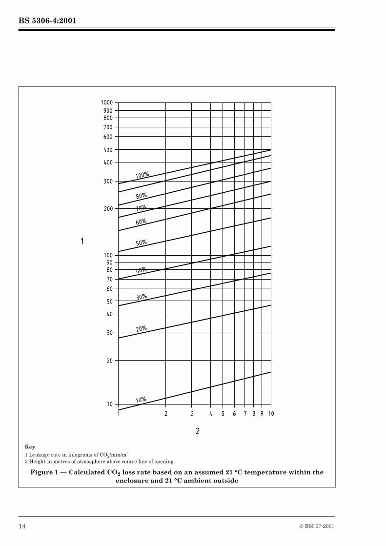
As the leakage rate through uncloseable openings in the absence of forced ventilation depends mainly on the difference in density between the atmosphere within the enclosure and the air surrounding the enclosure the following equation shall be used to calculate the rate of CO2 loss, assuming that there is sufficient leakage in the upper part of the enclosure to allow free ingress of air:
RM = 60 C�MAM 2 gM �M1 �M2–� �hM
�M1------------------------------------------------------
12 © BSI 07-2001
BS 5306-4:2001
where
NOTE Figure 1 may be used as a guide in estimating discharge rates for extended discharge systems.
COMMENTARY AND RECOMMENDATIONS ON 10.3.2.2. Where deep seated fires may be involved there should be no unclosable openings.
Where uncloseable openings are present an extended discharge in accordance with 10.3.2.2 should be used.
RM is the rate of loss of CO2 in kilograms per minute (kg/min);
C is the CO2 concentration fraction;
�M is the density of CO2 vapour in kilograms per cubic metre (kg/m3);
AM is the area of opening in square metres (m2) (flow coefficient included);
gM is the gravitational constant 9.81 m/s2;
�M1 is the density of atmosphere in kilograms per cubic metre (kg/m3);
�M2 is the density of surrounding air in kilograms per cubic metre (kg/m3);
hM is the static head between opening and top of enclosure in metres (m).
© BSI 07-2001 13
BS 5306-4:2001
Key
1 Leakage rate in kilograms of CO2/min/m2
2 Height in metres of atmosphere above centre line of opening
Figure 1 — Calculated CO2 loss rate based on an assumed 21 °C temperature within the enclosure and 21 °C ambient outside
1000
900800
700
600
500
400
300
200
1009080
70
60
50
40
30
20
10
1 2 3 4 5 6 7 8 9 10
100%
80%
70%
60%
50%
40%
30%
20%
10%
1
2
14 © BSI 07-2001
BS 5306-4:2001
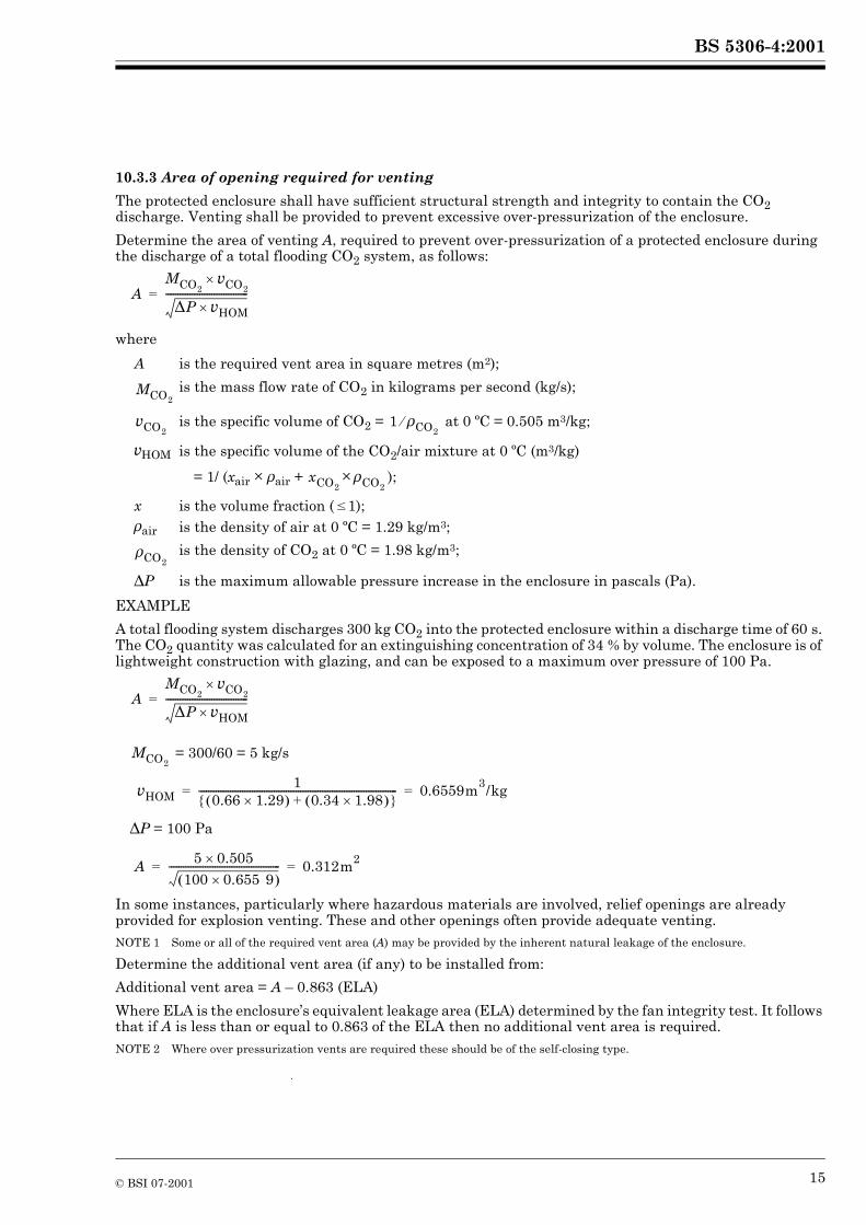
10.3.3 Area of opening required for venting
The protected enclosure shall have sufficient structural strength and integrity to contain the CO2 discharge. Venting shall be provided to prevent excessive over-pressurization of the enclosure.
Determine the area of venting A, required to prevent over-pressurization of a protected enclosure during the discharge of a total flooding CO2 system, as follows:
where
EXAMPLE
A total flooding system discharges 300 kg CO2 into the protected enclosure within a discharge time of 60 s. The CO2 quantity was calculated for an extinguishing concentration of 34 % by volume. The enclosure is of lightweight construction with glazing, and can be exposed to a maximum over pressure of 100 Pa.
= 300/60 = 5 kg/s
�P = 100 Pa
In some instances, particularly where hazardous materials are involved, relief openings are already provided for explosion venting. These and other openings often provide adequate venting.NOTE 1 Some or all of the required vent area (A) may be provided by the inherent natural leakage of the enclosure.
Determine the additional vent area (if any) to be installed from:
Additional vent area = A – 0.863 (ELA)
Where ELA is the enclosure’s equivalent leakage area (ELA) determined by the fan integrity test. It follows that if A is less than or equal to 0.863 of the ELA then no additional vent area is required.NOTE 2 Where over pressurization vents are required these should be of the self-closing type.
A is the required vent area in square metres (m2);
is the mass flow rate of CO2 in kilograms per second (kg/s);
is the specific volume of CO2 = at 0 ºC = 0.505 m3/kg;
�HOM is the specific volume of the CO2/air mixture at 0 ºC (m3/kg)
= 1/ (xair ������ � �air + �� );
x is the volume fraction (�1);�air is the density of air at 0 ºC = 1.29 kg/m3;
is the density of CO2 at 0 ºC = 1.98 kg/m3;
�P is the maximum allowable pressure increase in the enclosure in pascals (Pa).
AMCO2
�CO2�
�P �HOM�----------------------------------=
MCO2
�CO21 �CO2�
xCO2�CO2
�CO2
AMCO2
�CO2�
�P �HOM�----------------------------------=
MCO2
�HOM1
0.66 1.29�� � 0.34 1.98�� �+� �---------------------------------------------------------------------------------- 0.6559m3/kg= =
A 5 0.505�
100 0.655 9�� �---------------------------------------------- 0.312m2= =
© BSI 07-2001 15
BS 5306-4:2001
10.4 Carbon dioxide for surface fires
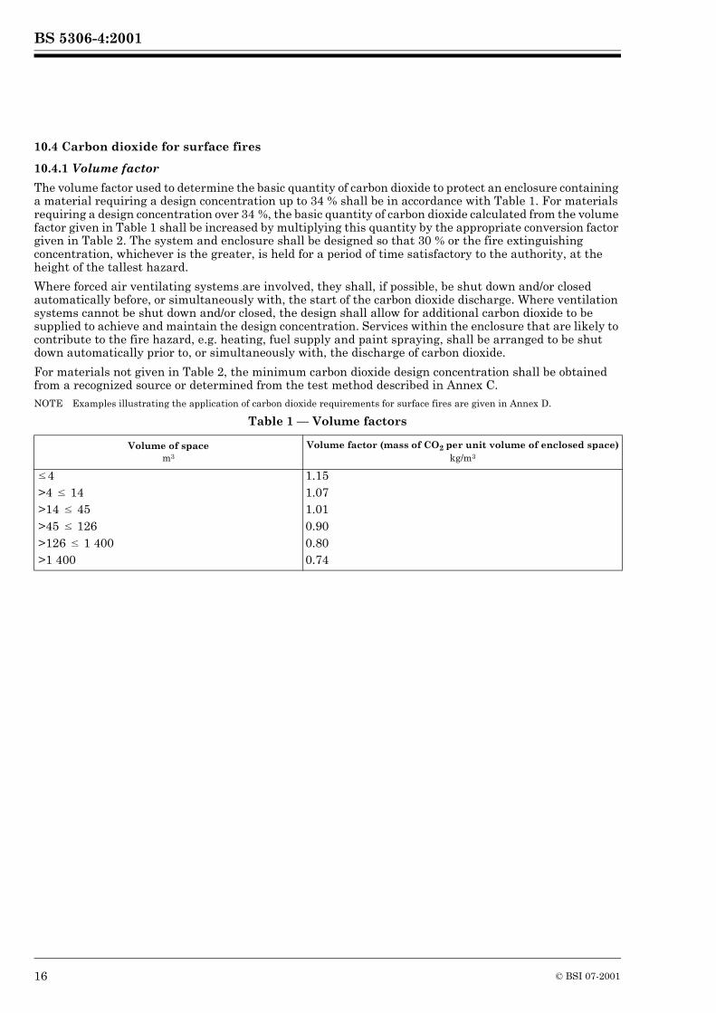
10.4.1 Volume factor
The volume factor used to determine the basic quantity of carbon dioxide to protect an enclosure containing a material requiring a design concentration up to 34 % shall be in accordance with Table 1. For materials requiring a design concentration over 34 %, the basic quantity of carbon dioxide calculated from the volume factor given in Table 1 shall be increased by multiplying this quantity by the appropriate conversion factor given in Table 2. The system and enclosure shall be designed so that 30 % or the fire extinguishing concentration, whichever is the greater, is held for a period of time satisfactory to the authority, at the height of the tallest hazard.
Where forced air ventilating systems are involved, they shall, if possible, be shut down and/or closed automatically before, or simultaneously with, the start of the carbon dioxide discharge. Where ventilation systems cannot be shut down and/or closed, the design shall allow for additional carbon dioxide to be supplied to achieve and maintain the design concentration. Services within the enclosure that are likely to contribute to the fire hazard, e.g. heating, fuel supply and paint spraying, shall be arranged to be shut down automatically prior to, or simultaneously with, the discharge of carbon dioxide.
For materials not given in Table 2, the minimum carbon dioxide design concentration shall be obtained from a recognized source or determined from the test method described in Annex C.NOTE Examples illustrating the application of carbon dioxide requirements for surface fires are given in Annex D.
Table 1 — Volume factors
Volume of spacem3
Volume factor (mass of CO2 per unit volume of enclosed space)kg/m3
�4 1.15>4 � 14 1.07>14 � 45 1.01>45 � 126 0.90>126 � 1 400 0.80>1 400 0.74
16 © BSI 07-2001
BS 5306-4:2001
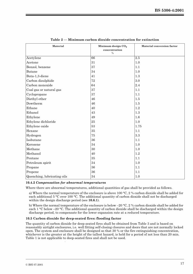
Table 2 — Minimum carbon dioxide concentration for extinction
10.4.2 Compensation for abnormal temperatures
Where there are abnormal temperatures, additional quantities of gas shall be provided as follows.
a) Where the normal temperature of the enclosure is above 100 °C, 2 % carbon dioxide shall be added for each additional 5 °C over 100 °C. The additional quantity of carbon dioxide shall not be discharged within the design discharge period (see 10.6.1).
b) Where the normal temperature of the enclosure is below –20 °C, 2 % carbon dioxide shall be added for each 1 °C below –20 °C. The additional quantity of carbon dioxide shall be discharged within the design discharge period, to compensate for the lower expansion rate at a reduced temperature.
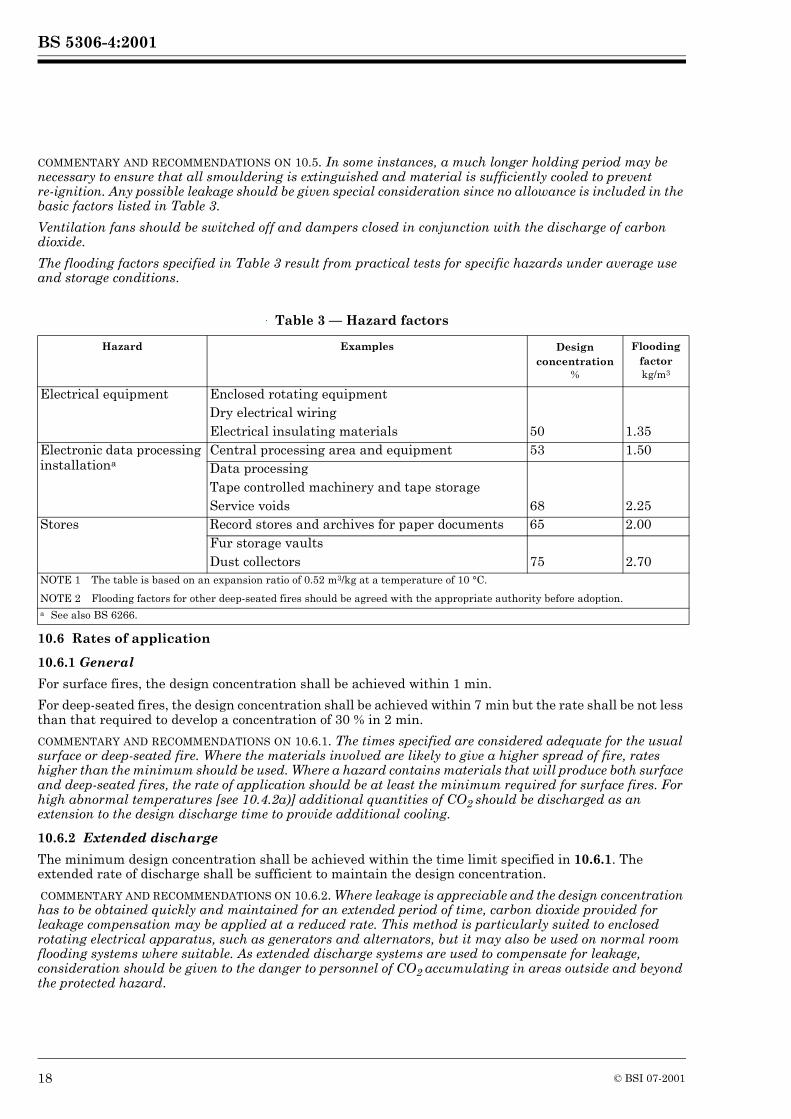
10.5 Carbon dioxide for deep-seated fires: flooding factor
The quantity of carbon dioxide for deep-seated fires shall be obtained from Table 3 and is based on reasonably airtight enclosures, i.e. well fitting self-closing closures and doors that are not normally locked open. The system and enclosure shall be designed so that 30 % or the fire extinguishing concentration, whichever is the greater at the height of the tallest hazard, is held for a period of not less than 20 min. Table 1 is not applicable to deep-seated fires and shall not be used.
Material Minimum design CO2
concentration%
Material conversion factor
Acetylene 66 2.5Acetone 31 1.0Benzol, benzene 37 1.1Butane 34 1.0Buta-1,3-diene 41 1.3Carbon disulphide 72 3.0Carbon monoxide 64 2.4Coal gas or natural gas 37 1.1Cyclopropane 37 1.1Diethyl ether 46 1.5Dowtherm 46 1.5Ethane 40 1.2Ethanol 43 1.3Ethylene 49 1.6Ethylene dichloride 25 1.0Ethylene oxide 53 1.75Hexane 35 1.1Hydrogen 75 3.3Isobutane 36 1.1Kerosene 34 1.0Methane 30 1.0Methanol 40 1.2Pentane 35 1.1Petroleum spirit 34 1.0Propane 36 1.1Propene 36 1.1Quenching, lubricating oils 34 1.0
© BSI 07-2001 17
BS 5306-4:2001
COMMENTARY AND RECOMMENDATIONS ON 10.5. In some instances, a much longer holding period may be necessary to ensure that all smouldering is extinguished and material is sufficiently cooled to prevent re-ignition. Any possible leakage should be given special consideration since no allowance is included in the basic factors listed in Table 3.
Ventilation fans should be switched off and dampers closed in conjunction with the discharge of carbon dioxide.
The flooding factors specified in Table 3 result from practical tests for specific hazards under average use and storage conditions.
Table 3 — Hazard factors
10.6 Rates of application
10.6.1 General
For surface fires, the design concentration shall be achieved within 1 min.
For deep-seated fires, the design concentration shall be achieved within 7 min but the rate shall be not less than that required to develop a concentration of 30 % in 2 min.
COMMENTARY AND RECOMMENDATIONS ON 10.6.1. The times specified are considered adequate for the usual surface or deep-seated fire. Where the materials involved are likely to give a higher spread of fire, rates higher than the minimum should be used. Where a hazard contains materials that will produce both surface and deep-seated fires, the rate of application should be at least the minimum required for surface fires. For high abnormal temperatures [see 10.4.2a)] additional quantities of CO2 should be discharged as an extension to the design discharge time to provide additional cooling.
10.6.2 Extended discharge
The minimum design concentration shall be achieved within the time limit specified in 10.6.1. The extended rate of discharge shall be sufficient to maintain the design concentration.
COMMENTARY AND RECOMMENDATIONS ON 10.6.2. Where leakage is appreciable and the design concentration has to be obtained quickly and maintained for an extended period of time, carbon dioxide provided for leakage compensation may be applied at a reduced rate. This method is particularly suited to enclosed rotating electrical apparatus, such as generators and alternators, but it may also be used on normal room flooding systems where suitable. As extended discharge systems are used to compensate for leakage, consideration should be given to the danger to personnel of CO2 accumulating in areas outside and beyond the protected hazard.
Hazard Examples Design concentration
%
Flooding factorkg/m3
Electrical equipment Enclosed rotating equipmentDry electrical wiringElectrical insulating materials 50 1.35
Electronic data processing installationa
Central processing area and equipment 53 1.50Data processingTape controlled machinery and tape storageService voids 68 2.25
Stores Record stores and archives for paper documents 65 2.00Fur storage vaultsDust collectors 75 2.70
NOTE 1 The table is based on an expansion ratio of 0.52 m3/kg at a temperature of 10 °C.
NOTE 2 Flooding factors for other deep-seated fires should be agreed with the appropriate authority before adoption.a See also BS 6266.
18 © BSI 07-2001
BS 5306-4:2001
10.6.3 Rotating electrical machinery
For enclosed rotating electrical machinery, a minimum concentration of 30 % shall be maintained for the deceleration period of the machine. This minimum concentration shall be held for the deceleration period or 20 min whichever is the longer.
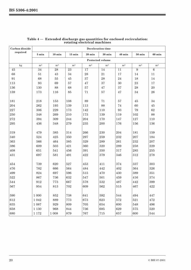
COMMENTARY AND RECOMMENDATIONS ON 10.6.3. Table 4 may be used as a guide to estimate the quantity of gas needed for the extended discharge to maintain the minimum concentration. The quantities are based on the internal volume of the machine and the deceleration time assuming average leakage. For dampered, non-recirculating type machines, 35 % should be added to the quantities given in Table 4.
10.7 Distribution systems
10.7.1 Design
Piping for total flooding systems shall be designed in accordance with clause 19 and clause 20 and to deliver the required rate of application at each nozzle.
COMMENTARY AND RECOMMENDATIONS ON 10.7.1. High pressure storage temperatures may range from –18 °C to 55 °C without requiring special methods of compensating for changing flow rates. Storage temperatures outside those limits require special design considerations to ensure proper flow rates.NOTE Annex E gives a method and example of pipe size determination.
10.7.2 Nozzle selection and distribution
The nozzles shall be arranged in the protected space in a manner that will ensure adequate, prompt and equal distribution of the carbon dioxide.
The nozzles shall be located in the upper part of the flooding zone. If the flooding zone is between 5 m and 10 m in height, additional nozzles shall be installed at one third the room height. The lower nozzles shall deliver one third of the design quantity. NOTE In the case of rooms higher than 10 m it may be necessary to have rows of nozzles at levels of 5 m spacings in order to achieve even distribution of the design quantity.
COMMENTARY AND RECOMMENDATIONS ON 10.7.2. Special consideration should be given to areas within the space that are of particular danger.
The type of nozzle selected and the disposition of the individual nozzles should be such that the discharge will not splash flammable liquids, dislodge ceiling tiles or create dust clouds that might extend the fire, create an explosion or otherwise adversely affect the contents of the enclosure. Nozzles vary in design and discharge characteristics and should be selected on the basis of their adequacy for the intended use.
© BSI 07-2001 19
BS 5306-4:2001
Table 4 — Extended discharge gas quantities for enclosed recirculation: rotating electrical machines
Carbon dioxide required
Deceleration time
5 min 10 min 15 min 20 min 30 min 40 min 50 min 60 min
Protected volume
kg m3 m3 m3 m3 m3 m3 m3 m3
45 34 28 23 17 14 11 9 668 51 43 34 28 21 17 14 1191 68 55 45 37 28 24 18 14
113 93 69 57 47 37 30 23 17136 130 88 68 57 47 37 28 20159 173 116 85 71 57 47 34 26
181 218 153 108 89 71 57 45 34204 262 193 139 113 88 74 60 45227 306 229 173 142 110 93 79 62250 348 269 210 173 139 119 102 88272 394 309 244 204 170 147 127 110295 436 348 279 235 200 176 156 136
319 479 385 314 266 230 204 181 159340 524 425 350 297 259 232 207 184363 566 464 385 329 289 261 232 207386 609 503 421 360 320 289 258 229408 651 541 456 391 350 317 285 255431 697 581 491 422 379 346 312 278
454 739 620 527 453 411 374 337 303476 782 666 564 484 442 402 364 326499 824 697 596 515 470 430 389 351522 867 736 632 547 501 459 416 374544 912 773 667 578 532 487 442 399567 954 813 702 609 562 515 467 422
590 1 000 852 738 641 592 544 494 447612 1 042 889 773 673 623 572 521 472635 1 087 929 809 705 654 600 548 496658 1 130 968 844 736 685 629 575 520680 1 172 1 008 879 767 715 657 600 544
20 © BSI 07-2001
BS 5306-4:2001
11 Local application systems
11.1 Uses
Local application systems shall conform to clause 6, clause 7, clause 8, and clause 9, unless otherwise specified in clause 11 and may be used for the extinguishment of surface fires in flammable liquids, gases and shallow solids where the hazard is not enclosed or where the enclosure does not conform to the requirements for total flooding (see 11.3.2).NOTE Examples of hazards that may be successfully protected by local application systems are:
a) coating machines;
b) dip tanks;
c) quench tanks;
d) printing presses;
e) textile machinery;
f) food processing;
g) spray booths;
h) fume ducts;
i) process machinery;
j) oil-filled electric transformers and switchgear.
Open cable or pipe trenches (possibly covered with chequer plate or similar) crossing, or adjacent to, a hazardous area should also be considered as being protected as part of the risk.
11.2 General design
11.2.1 Quantities of carbon dioxide for local application systems shall be determined by using the methods described in 11.7 and 11.8. The equation and tables for total flooding systems in clause 10 are not appropriate and shall not be used.
COMMENTARY AND RECOMMENDATIONS ON 11.2.1. Local application systems should be designed to deliver carbon dioxide to the hazard in a manner that will cover or surround the protected areas with carbon dioxide during the discharge time of the system.
The rate of application and the time for which it is necessary to maintain the extinguishing concentration will vary according to the hazard.
High pressure storage temperatures may range from 0 °C to 46 °C without requiring special methods of compensating for changing flow rates.
11.2.2 The system shall be designed for either:
a) automatic and manual operation;
b) manual operation only.NOTE This may be dependent upon the requirements of the relevant authority.
11.2.3 Where adjacent hazards cannot be isolated and fire spread is likely, they shall be treated as one hazard.
COMMENTARY AND RECOMMENDATIONS ON 11.2.3. Without prejudice to statutory provisions which are applicable to the design of the plant, that may require the containment and/or enclosure of flammable materials and operations involving manipulation of them, consideration should be given to enclosing the area including the provision of a low wall or bund. This will not only retain the extinguishing medium, but will also reduce the chances of fire entering or leaving the protected space.
Care should be taken to cover the whole hazard, particularly any surrounding areas liable to splashing, dripping, leakage or spillage, and to include all associated materials and/or equipment, such as freshly coated stock, drain boards, hoods and ducts, that might extend fire outside, or lead fire into, the protected space.
© BSI 07-2001 21
BS 5306-4:2001
The location of the hazard should be considered. It can be:
a) without weather protection;
b) under a roof without walls; or
c) completely enclosed.
It is essential that the carbon dioxide discharge should not be diverted by strong winds or air currents. Whilst it is possible to compensate for this by increasing the volume of discharge, consideration should be given to reducing the effect by wind breaks, screens or even total weather protection.
11.2.4 Hazards involving deep layer flammable liquid fires shall have a minimum freeboard of 150 mm in order to prevent splashing and to retain a surface concentration when carbon dioxide is applied.
11.3 Quantity of carbon dioxide
11.3.1 General
The quantity of carbon dioxide required for local application systems shall be determined by either the surface area method or the volume method depending upon the type of risk.
The surface area method shall be used where the areas to be protected are clearly defined surfaces whether in the horizontal, vertical or inclined planes.
The volume method shall be used where the irregular shape of the hazard is such that the surface area method cannot be used.
COMMENTARY AND RECOMMENDATIONS ON 11.3.1. Combined surface area and volume method may be used where the shape of the risk is such that the quantity of carbon dioxide cannot be determined by one of the methods alone.
11.3.2 High pressure storage systems
For systems with high pressure storage, the computed quantity of carbon dioxide shall be increased by 40 % to determine the nominal container storage capacity since only the liquid portion of the discharge is effective.
The computed quantity of carbon dioxide shall be calculated as follows:
ML = � TL
where
Thus the quantity of carbon dioxide required in high pressure storage shall be given by:
MS = ML � 1.4
where
MS is the stored quantity of carbon dioxide in kilograms (kg).
COMMENTARY AND RECOMMENDATIONS ON 11.3.2. This increase in container storage capacity is not required for the total flooding portion of combined local application/total flooding systems.
11.4 Rates of discharge
11.4.1 The total rate of discharge for local application systems shall be the sum of the individual rates of all the nozzles or discharge devices used on the system.
11.4.2 For low pressure systems, if a part of the hazard is to be protected by total flooding, the discharge rate for the total flooding part shall be sufficient to develop the required concentration in not more than the discharge time used for the local application part of the system.
ML is the computed quantity of carbon dioxide in kilograms (kg);
is the total of the discharge rate for all the individual nozzles in the system in kilograms per minute (kg/min);
TL is the liquid discharge time for the local application portion in minutes.
Qn�
Qn�
22 © BSI 07-2001
BS 5306-4:2001
11.4.3 For high pressure systems, if a part of the hazard is to be protected by total flooding, the discharge rate, QF, in kilograms per minute (kg/min) for the total flooding portion shall be calculated from the equation:
where
11.5 Duration of discharge
The minimum effective liquid discharge time for computing quantity shall be 30 s except as specified in 11.6. In low pressure systems the pre-liquid gaseous discharge period shall not be included in the 30 s liquid discharge time.
COMMENTARY AND RECOMMENDATIONS ON 11.5. The minimum time should be increased to compensate for any hazard condition that would require a longer cooling period to ensure complete extinction.
The gas quantities specified in this standard (see 11.3) are minimum requirements and it is important to realize that conditions such as high temperatures and cooling of unusually hot surfaces within the hazard area may require an increase in the discharge time and a corresponding increase in gas quantities to prevent re-ignition.
Fires apparently extinguished by carbon dioxide may re-ignite after the smothering atmosphere has dispersed if smouldering embers or hot surfaces remain.
11.6 Liquids of low auto-ignition temperature
The minimum discharge time for carbon dioxide being applied to liquids that have auto-ignition temperatures lower than their boiling temperature shall be 3 min.
COMMENTARY AND RECOMMENDATIONS ON 11.6. Common cooking oils and melted paraffin wax have auto-ignition temperatures lower than their boiling temperatures. In order to prevent re-ignition of these materials it is necessary to maintain an extinguishing atmosphere until the fuel has cooled below its auto-ignition temperature. Typical examples are deep fat fryers and quenching tanks.
11.7 Surface area method
11.7.1 General
The quantity of carbon dioxide required shall be based on the total discharge rate from a carefully sited nozzle arrangement.
11.7.2 Location and number of nozzles
A sufficient number of nozzles shall be used to cover the entire hazard area on the basis of each nozzle’s location or distance from the hazard and its design discharge rate.
In computing the total quantity of carbon dioxide required, the flow rates for all nozzles shall be added together to obtain the total flow rate for protection of the particular hazard. This rate shall be multiplied by the discharge time and, where applicable, the material conversion factor from Table 2.
11.7.3 Irregular shapes
When coated rollers or other similar irregular shapes are to be protected, the developed wetted area shall be used to determine the number of nozzles required.
COMMENTARY AND RECOMMENDATIONS ON 11.7.3. Where coated surfaces are to be protected, the area per nozzle may be increased by 40 % over the manufacturer’s test data. Coated surfaces are defined as those designed for drainage which are constructed and maintained so that no pools of liquid will accumulate over a total area exceeding 10 % of the protected surface. These recommendations do not apply where there is a heavy build-up of residue.
MF is the total quantity of carbon dioxide for the total flooding portion in kilograms (kg);
TL is the liquid discharge time for the local application portion in minutes.
QF
MF1.4TL----------------=
© BSI 07-2001 23
BS 5306-4:2001
EXAMPLE OF CALCULATION
Hazard: quench tank (material conversion factor, MCF = 1)
Surface dimensions:
width: 0.92 m;
length: 2.13 m.
Nozzle location: assume that a survey indicates that nozzles can be positioned anywhere from 0.92 m to 1.83 m away from the liquid surface without interfering with the operation.
From the manufacturer’s list of approved nozzles [a series of rated nozzles with their respective area of coverage at a given height above the surface to be protected and a given flow rate in kilograms per minute (kg/min)] select the minimum number of nozzles that will cover an area of 2.13 m � 0.92 m. Assume that the list has a nozzle which has a rated coverage of 1.08 m2 at a height of 1.52 m and a rated flow of 22.3 kg/min. Two nozzles will then cover a length of 2.16 m and a width of 1.08 m.
Total flow rate = 2 � 22.3 = 44.6 kg/min.
Carbon dioxide requirement = 44.6 � 0.5 � 1.4 (includes vapour) = 31.2 kg.
11.8 Volume method
11.8.1 General
The total discharge rate of local application systems shall be based on the volume of an assumed enclosure entirely surrounding the hazard. The assumed enclosure shall be based on an actual closed floor unless special provisions are made to take care of openings in the floor.
The assumed walls and ceiling of this enclosure shall be at least 600 mm from the main hazard, unless actual walls are involved, and they shall enclose all areas of possible leakage, splashing or spillage. No deductions shall be made for solid objects within this volume.
A minimum dimension of 1.2 m shall be used in calculating the volume of the assumed enclosure.NOTE It is assumed that the hazard is not subjected to winds or forced draughts sufficient to dissipate the carbon dioxide.
COMMENTARY AND RECOMMENDATIONS ON 11.8.1. The volume method of system design is used where the fire hazard consists of three-dimensional irregular objects that cannot be easily reduced to equivalent surface areas.
11.8.2 System discharge rate
The total discharge rate for the basic system shall be equal to 16 kg/min/m3 of assumed volume for enclosures with no walls.
If the assumed enclosure is partly defined by permanent continuous walls extending at least 600 mm above the hazard (where the walls are not normally a part of the hazard), the discharge rate shall be proportionately reduced to not less than 4 kg/min/m3 for walls completely surrounding the enclosure. In computing the quantity of carbon dioxide required, the total discharge rate shall be multiplied by the discharge time and, where applicable, the material conversion factor from Table 2.NOTE Examples of calculations are given in Annex D.
COMMENTARY AND RECOMMENDATIONS ON 11.8.2. Nozzles should be located and directed so as to retain the discharging carbon dioxide within the hazard volume by suitable coordination between nozzles and objects in the hazard volume. Nozzles should be located so as to compensate for any possible effects of air currents, winds or forced draughts.
11.9 Distribution system
11.9.1 General
The piping shall be designed in accordance with clause 19 and clause 20 to deliver the required rate of application at each nozzle.
24 © BSI 07-2001
BS 5306-4:2001
COMMENTARY AND RECOMMENDATIONS ON 11.9.1. Where long pipelines are required or where the piping may be exposed to higher than normal temperatures, the quantity of carbon dioxide should be increased by an amount sufficient to compensate for liquid carbon dioxide vaporized in cooling the piping. The pipeline should be as direct as practicable with a minimum number of bends.
High pressure storage temperatures may range from 0 °C to 46 °C without requiring special methods of compensating for changing flow rates.NOTE Annex E gives a method and examples of pipe size determination.
11.9.2 Distribution nozzles
The rate of carbon dioxide per nozzle shall be determined from the performance data provided by the manufacturer or other competent authority.
System design shall be based on listing or approved data for individual nozzles. Extrapolation of such data above or below the upper or lower limits shall not be made.
The equivalent orifice size used in each nozzle shall be determined in accordance with 20.9 to match the design discharge rate.
COMMENTARY AND RECOMMENDATIONS ON 11.9.2. The area covered by each nozzle will vary according to the type of nozzle, orifice size, height and angle of the projection.
The same factors used to determine the design discharge rate should be used to determine the maximum area to be protected by each nozzle.
Nozzles should be located so as to be free of possible obstructions that could interfere with the proper projection of the discharge of carbon dioxide.
Nozzles should be located so as to develop an extinguishing atmosphere over coated items extending above a protected surface. Additional nozzles may be required for this specific purpose, particularly if items extend more than 600 mm above a protected surface.
The possible effects of air currents, winds and forced draughts should be compensated for by proper location of nozzles or by provision of additional nozzles to protect adequately the outside areas of hazard.
11.9.3 Overhead nozzles
The discharge rate for overhead type nozzles shall be determined on the basis of distance from the surface in accordance with the manufacturer’s instructions.
The portion of the hazard protected by individual overhead type nozzles shall be considered as a square area.
Overhead type nozzles shall either be installed perpendicularly to the hazard and centered over the area protected by the nozzle or be installed at angles between 45° and 90° from the plane of the hazard surface as specified in 11.9.5. The height used in determining the necessary flow rate and area coverage shall be the distance from the aiming point on the protected surface to the face of the nozzle measured along the axis of the nozzle (see Figure 2).
11.9.4 Tankside nozzles
The discharge rate for tankside nozzles shall be determined solely on the basis of throw or projection required to cover the surface each nozzle protects.
The portion of the hazard protected by individual tankside or linear nozzles shall be either a rectangular or a square area in accordance with spacing and discharge limitations stated in specific approvals or listings.
Tankside or linear type nozzles shall be located in accordance with spacing and discharge rate limitations stated in specific approvals or listings.
11.9.5 Nozzles installed at an angle
When installed at an angle, nozzles shall be aimed at a point measured from the near side of the area protected by the nozzle, the location of which is calculated by multiplying the fractional aiming factor in Table 5 by the width of the area protected by the nozzle (see Figure 2).
© BSI 07-2001 25
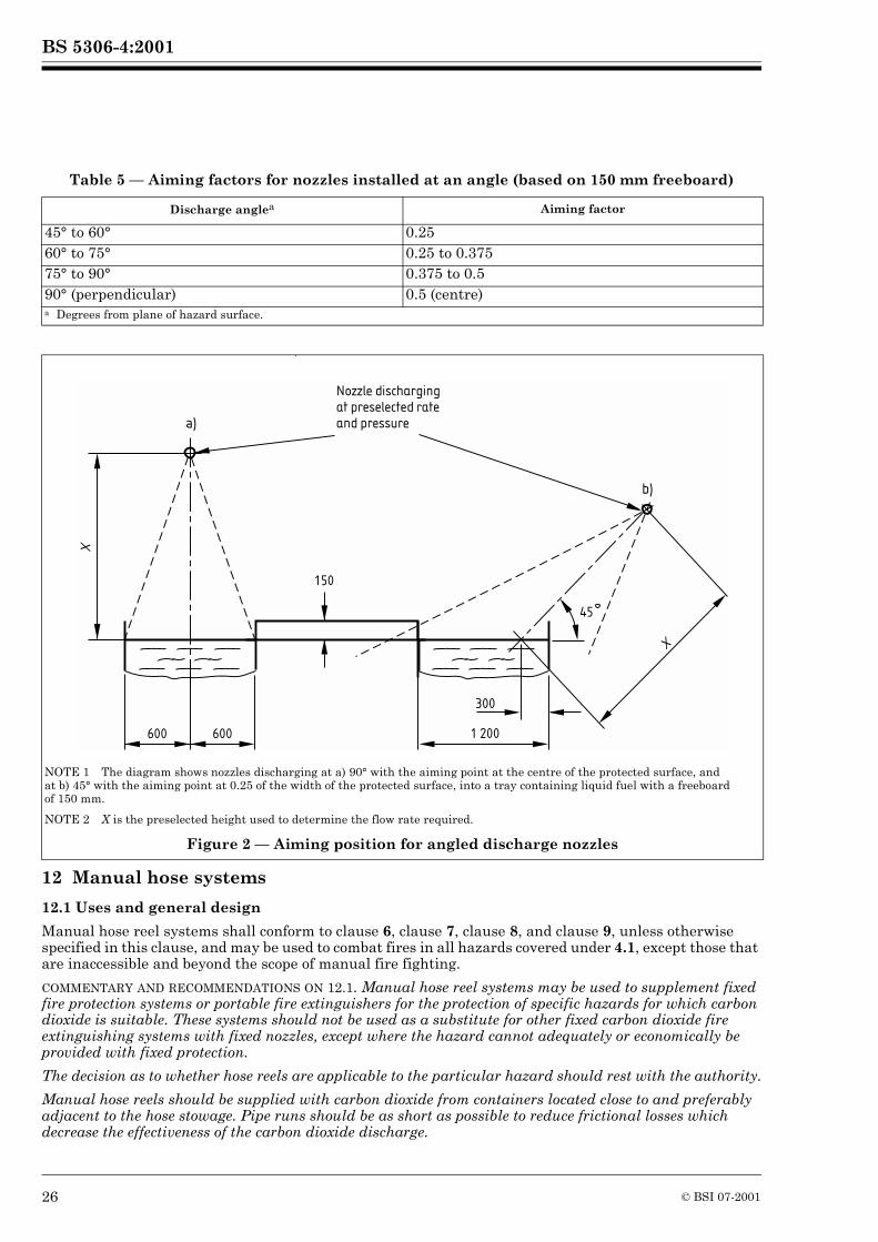
BS 5306-4:2001
Table 5 — Aiming factors for nozzles installed at an angle (based on 150 mm freeboard)
12 Manual hose systems
12.1 Uses and general design
Manual hose reel systems shall conform to clause 6, clause 7, clause 8, and clause 9, unless otherwise specified in this clause, and may be used to combat fires in all hazards covered under 4.1, except those that are inaccessible and beyond the scope of manual fire fighting.
COMMENTARY AND RECOMMENDATIONS ON 12.1. Manual hose reel systems may be used to supplement fixed fire protection systems or portable fire extinguishers for the protection of specific hazards for which carbon dioxide is suitable. These systems should not be used as a substitute for other fixed carbon dioxide fire extinguishing systems with fixed nozzles, except where the hazard cannot adequately or economically be provided with fixed protection.
The decision as to whether hose reels are applicable to the particular hazard should rest with the authority.
Manual hose reels should be supplied with carbon dioxide from containers located close to and preferably adjacent to the hose stowage. Pipe runs should be as short as possible to reduce frictional losses which decrease the effectiveness of the carbon dioxide discharge.
Discharge anglea Aiming factor
45° to 60° 0.2560° to 75° 0.25 to 0.37575° to 90° 0.375 to 0.590° (perpendicular) 0.5 (centre)a Degrees from plane of hazard surface.
NOTE 1 The diagram shows nozzles discharging at a) 90° with the aiming point at the centre of the protected surface, and at b) 45° with the aiming point at 0.25 of the width of the protected surface, into a tray containing liquid fuel with a freeboard of 150 mm.
NOTE 2 X is the preselected height used to determine the flow rate required.
Figure 2 — Aiming position for angled discharge nozzles
600 600
300
150
45
1 200
Nozzle discharging
at preselected rate
and pressure
X
a)
b)
X
26 © BSI 07-2001
BS 5306-4:2001
Where manual hose reels are installed in addition to fixed fire protection systems, the carbon dioxide supply for the manual hose reel should be in addition to the quantity supplying the fixed fire protection system.
12.2 Hazard to personnel
Where the discharge of a manual hose reel system may lead to personnel being exposed to high concentrations of carbon dioxide the safety precautions of clause 15 shall be applied.
COMMENTARY AND RECOMMENDATIONS ON 12.2. As stated in 4.2, the discharge of large amounts of carbon dioxide to fight fire may create a hazard to personnel. The quantity of carbon dioxide that will be discharged, related to the volume and geometry of the total enclosure, should be taken into account. If it is considered that the developed concentration of carbon dioxide could be hazardous to personnel, the safety precautions set out in clause 15 should be applied, and personnel escape routes should also be considered.
12.3 Location and spacing of manual hose reels
12.3.1 Manual hose reels shall be located where they will be accessible during a fire and within reach of the protected hazards. Actuating controls shall be located at the hose reel station. Reels shall be ready for immediate use.
12.3.2 If multiple hose reel stations are used, they shall be spaced so that any area within the hazard is covered by one or more hose reels.
12.4 Rate and duration of discharge
12.4.1 General
The rate and duration of discharge and consequently the amount of carbon dioxide shall be determined by the type and potential size of the hazard. A manual hose reel system shall have sufficient quantity of carbon dioxide to permit its effective (liquid phase) use for at least 1 min.
12.4.2 Simultaneous use of hose reels
Where simultaneous use of two or more hose lines is possible, a sufficient quantity of carbon dioxide shall be available to supply the maximum number of nozzles that are likely to be used at any one time for at least 1 min.
12.5 Equipment design
12.5.1 Hose
Hoses used on systems with high pressure supply shall be designed in accordance with BS EN 856 for a working pressure of 190 bar. Hoses used on systems with a low pressure supply shall operate safely at a working pressure of 27 bar.
12.5.2 Discharge nozzle assembly
Hose reels shall be equipped with a discharge nozzle assembly intended for use by one person. This shall incorporate a quick opening shut-off valve to control the flow of carbon dioxide through the nozzle for directing the discharge, which shall be provided with a suitable insulated handle.
COMMENTARY AND RECOMMENDATIONS ON 12.5.2. For ease of manipulation the discharge nozzle assembly should be attached to the hose by a swivel connection.
12.6 Charging the hose reel
All controls for actuating the system shall be located in the immediate vicinity of the hose reel storage.NOTE Except when the hose line is in actual use, pressure should not be permitted to remain in the system.
COMMENTARY AND RECOMMENDATIONS ON 12.6. Operation of manual hose reel systems depends upon manual actuation and manual manipulation of a discharge nozzle. Speed and simplicity of operation is, therefore, essential for successful extinction.
13 System componentsPrincipal components shall conform to and be installed in accordance with the appropriate part of BS EN 12094 and the manufacturer’s instructions.
© BSI 07-2001 27
BS 5306-4:2001
All devices shall be designed for the service they will encounter and shall not be readily rendered inoperative or susceptible to accidental operation. Devices shall normally be designed to function properly from –20 °C to +50 °C or shall be marked to indicate their temperature limitations.
Where the pressure of a permanent gas from pilot containers is used as a means of releasing the system, the container shall be continuously monitored and a fault alarm given in the event of pressure loss in excess of 10 %.
Where the pressure of a liquified gas from pilot containers is used as a means of releasing the system, the container shall be continuously monitored and a fault alarm given in the event of excessive weight loss or be duplicated.
COMMENTARY AND RECOMMENDATIONS ON CLAUSE 13. Various operating devices are necessary to control the flow of the extinguishing agent to operate the associated equipment. These include container valves, distribution valves, automatic and manual controls, delay devices, pressure trips and switches and discharge nozzles.
All devices, especially those having external moving parts, should be located, installed or suitably protected so that they are not subject to mechanical, chemical or other damage that would render them inoperable.
14 System operation
14.1 Manual control
Provision shall be made for manual operation of the fire fighting system by means of a control situated outside the protected space or adjacent to the main exit from the space.
In addition to any means of automatic operation, the system shall be provided with the following:
a) one or more means, remote from the containers, of manual operation;
b) a manual device for providing direct mechanical actuation of the system; or
c) an electrical manual release system in which the control equipment monitors for abnormal conditions in the power supply and provides a signal when the power source is inadequate.
Manual operation shall cause simultaneous operation of the appropriate automatically operated valves for CO2 release and distribution.
The manual operation device shall incorporate a double action or other safety device to restrict accidental operation. The device shall be provided with a means of preventing operation during maintenance of the system.NOTE The choice of means of operation will depend on the nature of the hazard to be protected. Automatic fire detection and alarm equipment will normally be provided on a manual system to indicate the presence of a fire.
Mechanical manual devices that cause direct release of gas shall not be positioned inside the protected area.
COMMENTARY AND RECOMMENDATIONS ON 14.1. Manual controls should be located so as to be conveniently and easily accessible at all times, including at the time of fire, and should preferably be outside the protected space.
Emergency manual operation of individual system components is usually by manual direct operation of the device to be operated.
14.2 Automatic operation
14.2.1 Automatic systems shall be controlled by appropriate automatic fire detection and release devices selected according to the requirements of the particular hazard.
COMMENTARY AND RECOMMENDATIONS ON 14.2.1. Electrically, pneumatically or mechanically operated devices may be used.
14.2.2 Electrically operated devices shall conform to BS 7273-1.
The power supply shall be independent of the supply for the hazardous area. Where this is not practicable, pneumatic or mechanical devices shall be used, or the system shall be provided with emergency secondary power supplies with automatic changeover in case the primary supply fails.
14.2.3 Mechanical or pneumatically operated devices shall conform to BS 7273-2.
28 © BSI 07-2001
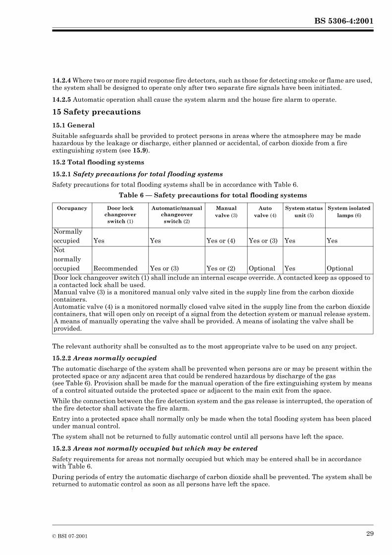
BS 5306-4:2001
14.2.4 Where two or more rapid response fire detectors, such as those for detecting smoke or flame are used, the system shall be designed to operate only after two separate fire signals have been initiated.
14.2.5 Automatic operation shall cause the system alarm and the house fire alarm to operate.
15 Safety precautions
15.1 General
Suitable safeguards shall be provided to protect persons in areas where the atmosphere may be made hazardous by the leakage or discharge, either planned or accidental, of carbon dioxide from a fire extinguishing system (see 15.9).
15.2 Total flooding systems
15.2.1 Safety precautions for total flooding systems
Safety precautions for total flooding systems shall be in accordance with Table 6.
Table 6 — Safety precautions for total flooding systems
The relevant authority shall be consulted as to the most appropriate valve to be used on any project.
15.2.2 Areas normally occupied
The automatic discharge of the system shall be prevented when persons are or may be present within the protected space or any adjacent area that could be rendered hazardous by discharge of the gas (see Table 6). Provision shall be made for the manual operation of the fire extinguishing system by means of a control situated outside the protected space or adjacent to the main exit from the space.
While the connection between the fire detection system and the gas release is interrupted, the operation of the fire detector shall activate the fire alarm.
Entry into a protected space shall normally only be made when the total flooding system has been placed under manual control.
The system shall not be returned to fully automatic control until all persons have left the space.
15.2.3 Areas not normally occupied but which may be entered
Safety requirements for areas not normally occupied but which may be entered shall be in accordance with Table 6.
During periods of entry the automatic discharge of carbon dioxide shall be prevented. The system shall be returned to automatic control as soon as all persons have left the space.
Occupancy Door lock changeover switch (1)
Automatic/manual changeover switch (2)
Manual valve (3)
Auto valve (4)
System status unit (5)
System isolated lamps (6)
Normally occupied Yes Yes Yes or (4) Yes or (3) Yes YesNotnormally occupied Recommended Yes or (3) Yes or (2) Optional Yes OptionalDoor lock changeover switch (1) shall include an internal escape override. A contacted keep as opposed to a contacted lock shall be used.Manual valve (3) is a monitored manual only valve sited in the supply line from the carbon dioxide containers.Automatic valve (4) is a monitored normally closed valve sited in the supply line from the carbon dioxide containers, that will open only on receipt of a signal from the detection system or manual release system. A means of manually operating the valve shall be provided. A means of isolating the valve shall be provided.
© BSI 07-2001 29
BS 5306-4:2001
15.3 Local application systems
When unusual circumstances make it impossible for personnel to leave the space protected by a system within the period of the pre-discharge alarm, e.g. during difficult maintenance work, the automatic operation of the system shall be prevented using an appropriate method from Table 6.
COMMENTARY AND RECOMMENDATIONS ON 15.3. A local application system normally presents a lower risk to personnel than a total flooding system since the final developed concentration of extinguishant throughout the space will be lower. However, during the period of discharge it is necessary to produce an extinguishing concentration of gas around the protected area with a risk of high local concentrations. There is a further risk of higher concentrations of gas occurring in pits, wells, shaft bottoms and similar low areas.
The system may normally be on automatic control if, after considering the geometry of the area in which a local application system is used, it can be established that there is not a foreseeable risk of a hazardous concentration of carbon dioxide being produced in any occupied part.
In assessing the degree of risk to personnel of automatically controlled systems, the need to approach close to the point of discharge or to work within the confines of the protected area should be considered. If it is necessary for personnel to work within an area that is likely to be quickly enveloped with CO2 gas, consideration should be given to providing a pre-discharge alarm that gives sufficient warning to allow personnel to move away from the protected area before CO2 is released.
15.4 Additional requirements for all systems
15.4.1 Manifold venting
In systems using stop valves, release of the carbon dioxide from the storage containers shall activate a device which gives visual warning to indicate that carbon dioxide has been released and is trapped in the manifold.
In addition to the pressure relief device specified in 20.6 a manually operated vent valve shall be fitted to the manifold so that the trapped carbon dioxide can be safely vented to atmosphere. The vent valve shall normally be kept in the locked shut position.
15.4.2 Discharge prevention during maintenance
To enable system inspection and servicing to be carried out in safety and also during times when the protected area is undergoing alterations or extensive maintenance, a means shall be provided to prevent the discharge of carbon dioxide from the storage containers.
15.4.3 Audible and visual alarms
Alarms or indicators, or both, shall be used to indicate the operation of the system, hazards to personnel, or failure of any supervised device. The type (audible, visual or olfactory), number and location of the devices shall be such that their purpose is satisfactorily accomplished.
Audible and visual pre-discharge alarms shall be provided within the protected area to give positive warning of impending discharge. The operation of the warning devices shall be continued after CO2 discharge, until positive action has been taken to acknowledge the alarm and proceed with appropriate action.
Alarms indicating failure of supervised devices or equipment shall give prompt and positive indication of any failure and shall be distinct from alarms indicating operation or hazardous conditions.
COMMENTARY AND RECOMMENDATIONS ON 15.4.3. It is recommended that the following lamps and wording be used to identify system conditions:
— red lamp: CO2 discharged;— amber lamp: automatic and manual control;— green lamp: manual control;— blue or white lamp: isolated.
These system condition indicators are normally required only for total flooding systems but may be necessary in local application systems for example in the situations described in some applications described in 11.1. Duplication of the lamps will mitigate the effects of bulb failure.
30 © BSI 07-2001
BS 5306-4:2001
15.4.4 Odorizers
To enable CO2 to be detected during and following a discharge an odorizer shall be provided.
COMMENTARY AND RECOMMENDATIONS ON 15.4.4. Whilst odorizers provide an indication of CO2 during or following a discharge, consideration should be given to the provision of CO2 detection to detect slow leakage into the protected area or at the container location.
15.5 Confined spaces
As entry into confined spaces poses additional hazards because of restrictions on freedom of movement, ventilation and on escape or rescue, before entry into floor or ceiling voids, ducts, process vessels or similarly confined spaces that are protected by a gas flooding system, the operation of the system shall be prevented as in 15.4.2.
COMMENTARY AND RECOMMENDATIONS ON 15.5. Entry into confined spaces for any purpose should be controlled by a permit-to-work system. Provision should be made for ensuring that the atmosphere within the space is safe for entry and will remain so for the duration of entry. In cases where effective ventilation cannot be ensured, the permit should specify the respiratory protective equipment to be used and any other special precautions to be observed to ensure safe working conditions.
Attention is drawn to the Factories Act 1961, Section 30 [2].
15.6 Warning signs
Appropriate signs, as illustrated in Figure 3 or Figure 4, shall be prominently displayed at each manual control point (Figure 3) and at each entrance (Figure 4) to the area protected by the system.
15.7 Exits
Adequate means of egress from a protected space shall be provided. Doors at exits shall open outwards and shall be self-closing. All exit doors shall open readily from the inside and any that have to be secured shall be fitted with panic bolts or latches.
COMMENTARY AND RECOMMENDATIONS ON 15.7. These requirements are in addition to any imposed under the Fire Precautions Act 1971 [3].
The means of egress from a protected space should be kept clear at all times.
15.8 Manual hose reels
A notice with the wording “Only for use by trained personnel” shall be mounted on or adjacent to manual hose reels.
COMMENTARY AND RECOMMENDATIONS ON 15.8. The use of manual hose reels for the application of carbon dioxide may present a hazard to personnel. This method of fire control should be used only by trained personnel who have been adequately instructed and trained in the use of the equipment and in the safety precautions to be adopted. All persons other than those fighting the fire should be evacuated prior to the use of manual hose reels. Particular precautions are required where ventilation is restricted, in order to guard against hazards that may arise from the fire or the extinguishing medium. The provision of self-contained breathing apparatus for trained personnel should be considered.
© BSI 07-2001 31
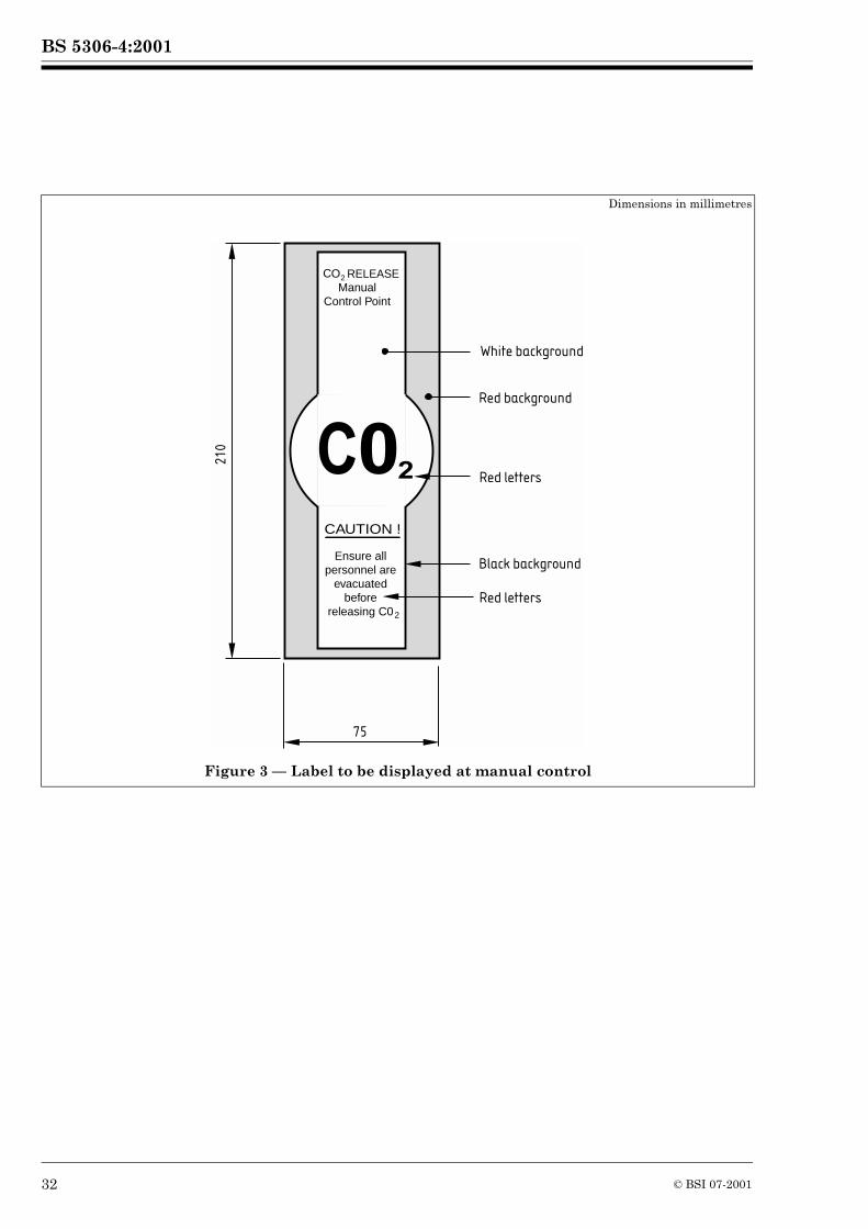
BS 5306-4:2001
Dimensions in millimetres
Figure 3 — Label to be displayed at manual control
White background
Red background
Red letters
Red letters
Black background
CAUTION !
75
21
0
Ensure allpersonnel are
evacuatedbefore
releasing C0
ManualControl Point
2
RELEASE CO2
C02
32 © BSI 07-2001
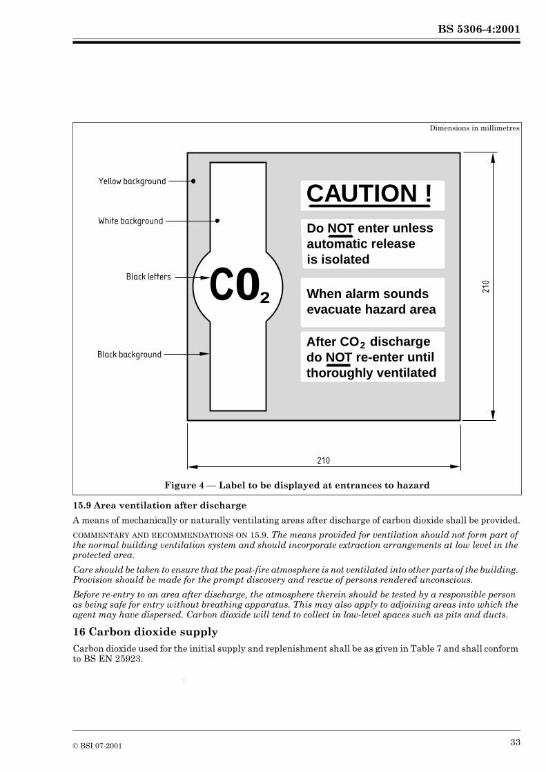
BS 5306-4:2001
15.9 Area ventilation after discharge
A means of mechanically or naturally ventilating areas after discharge of carbon dioxide shall be provided.
COMMENTARY AND RECOMMENDATIONS ON 15.9. The means provided for ventilation should not form part of the normal building ventilation system and should incorporate extraction arrangements at low level in the protected area.
Care should be taken to ensure that the post-fire atmosphere is not ventilated into other parts of the building. Provision should be made for the prompt discovery and rescue of persons rendered unconscious.
Before re-entry to an area after discharge, the atmosphere therein should be tested by a responsible person as being safe for entry without breathing apparatus. This may also apply to adjoining areas into which the agent may have dispersed. Carbon dioxide will tend to collect in low-level spaces such as pits and ducts.
16 Carbon dioxide supplyCarbon dioxide used for the initial supply and replenishment shall be as given in Table 7 and shall conform to BS EN 25923.
Dimensions in millimetres
Figure 4 — Label to be displayed at entrances to hazard
Yellow background
White background
Black background
After CO dischargedo NOT re-enter until thoroughly ventilated
2
C02 When alarm soundsevacuate hazard area
Do NOT enter unlessautomatic releaseis isolated
CAUTION !
Black letters
21
0
210
© BSI 07-2001 33
BS 5306-4:2001
Table 7 — Carbon dioxide requirements
COMMENTARY AND RECOMMENDATIONS ON CLAUSE 16. Carbon dioxide obtained by converting dry ice to liquid will not usually conform to these requirements unless it has been processed to remove excess oil and waste.
17 Quantity of carbon dioxide
17.1 In a high pressure system, the amount of carbon dioxide in the system shall be sufficient for the largest single hazard to be protected, or group of hazards to be protected simultaneously, and shall be determined as specified in clause 10, clause 11 and clause 12.
17.2 In a low pressure system, to compensate for possible variations in filling or discharge tolerances and gas residues, the amount of carbon dioxide in the system shall be increased by at least 10 % over the amount sufficient for the largest single hazard to be protected, or group of hazards to be protected simultaneously determined as specified in clauses 10, clause 11 and clause 12. In addition, for low pressure installations, the equivalent quantity of carbon dioxide that may remain liquid in the piping between the storage container and the nozzle pipework after completion of the designed discharge period shall be calculated and added to the required quantity of carbon dioxide.
17.3 Where more than one zone is protected by one battery of containers by means of distribution valves, or in other situations where there may be a need to recharge the plant quickly, consideration shall be given to the provision of additional reserve containers which may be free-standing spares or be permanently connected to the fixed piping system. In either case the containers supplied shall be equal in quantity to the initial bank.
COMMENTARY AND RECOMMENDATIONS ON CLAUSE 17. The determined quantity of carbon dioxide required for fixed fire extinguishing installations should be available at all times and not be used for other purposes including manual hose reel systems.
18 Storage containers
18.1 Storage conditions
18.1.1 Arrangements shall be made for container and valve assemblies and accessories to be accessible for inspection, testing and other maintenance when required.
18.1.2 Containers shall be adequately mounted and suitably supported according to the systems installation manual so as to provide for convenient individual servicing of the container and its contents.
18.1.3 Containers shall be located as near as practical to the enclosure they protect, preferably outside the enclosure. NOTE Containers can be located within the enclosure only if sited so as to minimize the risk of exposure to fire and explosion.
18.1.4 Storage containers shall not be located so as to be subject to severe weather conditions or to potential damage due to mechanical, chemical, or other causes. Where potentially damaging exposures or unauthorized interference are likely, suitable enclosures or guards shall be provided.NOTE Direct sunlight has the potential to increase the container temperature above that of the surrounding atmospheric temperature.
18.1.5 Each container shall be connected to the manifold via a non-return valve to enable individual containers to be removed from the system without interruption of the general protection.
18.1.6 The containers shall be secured against reaction when the carbon dioxide is discharged.
Property Requirement
Purity, % (V/V) min. 99.5Water content, % (m/m) max. 0.015Oil content, p.p.m. by mass, max. 5Total sulfur compounds content, expressed as sulfur, p.p.m. by mass, max. 1.0
34 © BSI 07-2001
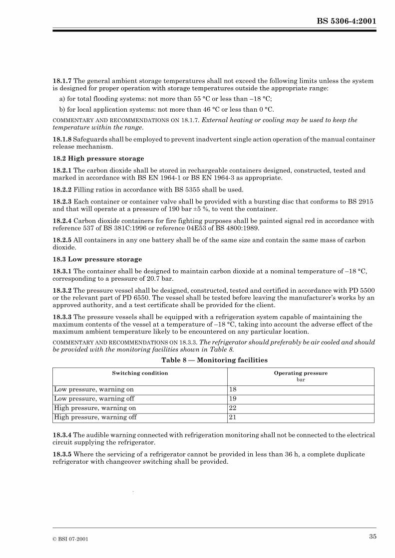
BS 5306-4:2001
18.1.7 The general ambient storage temperatures shall not exceed the following limits unless the system is designed for proper operation with storage temperatures outside the appropriate range:
a) for total flooding systems: not more than 55 °C or less than –18 °C;
b) for local application systems: not more than 46 °C or less than 0 °C.
COMMENTARY AND RECOMMENDATIONS ON 18.1.7. External heating or cooling may be used to keep the temperature within the range.
18.1.8 Safeguards shall be employed to prevent inadvertent single action operation of the manual container release mechanism.
18.2 High pressure storage
18.2.1 The carbon dioxide shall be stored in rechargeable containers designed, constructed, tested and marked in accordance with BS EN 1964-1 or BS EN 1964-3 as appropriate.
18.2.2 Filling ratios in accordance with BS 5355 shall be used.
18.2.3 Each container or container valve shall be provided with a bursting disc that conforms to BS 2915 and that will operate at a pressure of 190 bar ±5 %, to vent the container.
18.2.4 Carbon dioxide containers for fire fighting purposes shall be painted signal red in accordance with reference 537 of BS 381C:1996 or reference 04E53 of BS 4800:1989.
18.2.5 All containers in any one battery shall be of the same size and contain the same mass of carbon dioxide.
18.3 Low pressure storage
18.3.1 The container shall be designed to maintain carbon dioxide at a nominal temperature of –18 °C, corresponding to a pressure of 20.7 bar.
18.3.2 The pressure vessel shall be designed, constructed, tested and certified in accordance with PD 5500 or the relevant part of PD 6550. The vessel shall be tested before leaving the manufacturer’s works by an approved authority, and a test certificate shall be provided for the client.
18.3.3 The pressure vessels shall be equipped with a refrigeration system capable of maintaining the maximum contents of the vessel at a temperature of –18 °C, taking into account the adverse effect of the maximum ambient temperature likely to be encountered on any particular location.
COMMENTARY AND RECOMMENDATIONS ON 18.3.3. The refrigerator should preferably be air cooled and should be provided with the monitoring facilities shown in Table 8.
Table 8 — Monitoring facilities
18.3.4 The audible warning connected with refrigeration monitoring shall not be connected to the electrical circuit supplying the refrigerator.
18.3.5 Where the servicing of a refrigerator cannot be provided in less than 36 h, a complete duplicate refrigerator with changeover switching shall be provided.
Switching condition Operating pressurebar
Low pressure, warning on 18Low pressure, warning off 19High pressure, warning on 22High pressure, warning off 21
© BSI 07-2001 35
BS 5306-4:2001
18.3.6 A device shall be provided to indicate the carbon dioxide content in the vessel.
COMMENTARY AND RECOMMENDATIONS ON 18.3.6. For this purpose, the vessel may be placed on a weighing machine or be equipped with an automatic contents indicator. Where electrically operated indicators are provided, a monitored system should be used. Consideration should be given to the provision of alarm contacts on the contents gauge or weighing machine to give audible warning that it is necessary to recharge the vessel.
18.3.7 Each pressure vessel of less than 20 t capacity shall be equipped with at least two relief valves set to relieve pressure at 24 bar.
The relief valves shall be mounted in pairs on a two-way changeover valve arranged to ensure that one relief valve always provides protection against excessive pressure within the vessel. It shall not be possible for the two-way changeover valve to isolate both relief valves at the same time.
Vessels over 20 t capacity shall be provided with four relief valves arranged in pairs, set to relieve pressure at 24 bar, each pair to be provided with a changeover valve.
Extended balance and filling lines should also be fitted with relief devices.
Relief valves shall be fitted so that the discharge, in the event of operation, will not injure or endanger personnel. If necessary, the discharge shall be piped to an area where it will not become a hazard.
The location of the vessel shall be such that there is always sufficient ventilation to permit the refrigerator to function satisfactorily. If the vessel is located within a closed space, pressure-relieving devices shall be piped to atmosphere. In extremely cold locations where it is possible for the carbon dioxide to cool below a temperature of –24 °C, heating equipment shall be provided to maintain the temperature of the vessel contents within the limits already specified.
COMMENTARY AND RECOMMENDATIONS ON 18.3.7. Recharging with carbon dioxide following a discharge should be possible within 36 h. Otherwise increased capacity or a reserve tank should be provided.
Carbon dioxide supplied from a mobile tanker at a temperature significantly lower than that found within the vessel is likely to cause over-filling of the vessel at normal operating temperatures and thus cause the relief devices to operate.
19 Pipework
19.1 General
Pipework shall be non-combustible and able to withstand the expected pressures and temperatures without damage.
Threaded steel pipework and fittings, except those conforming to BS 3799, shall be galvanized inside and out.NOTE 1 Copper, copper alloy or stainless steel tube may be used without additional protection against corrosion.
Pipes and fittings shall be free of burrs, spelter and rust. Stainless steel, copper and copper alloy pipe and fittings for high pressure and low pressure systems shall conform to BS 3605-2 and BS EN 12449 (see note 2). Other steel pipe and fittings shall be as given in Table 9, Table 10, Table 11 and Table 12.NOTE 2 The grade of stainless steel, copper and copper alloy should be chosen in consultation with the manufacturer with regard to the duty to be performed.
For high pressure systems, container and valve manifolds shall be hydraulically tested at the manufacturer’s works to a minimum pressure of 190 bar. For low pressure systems container and valve manifolds shall be hydraulically tested to a minimum pressure of 33 bar. The installer shall provide for the issue of a test certificate.
19.2 Flanges
19.2.1 High pressure systems
19.2.1.1 For closed sections of pipework, flanges shall be of forged carbon steel, raised face, conforming to class 900 of ANSI B16.5:1996.
19.2.1.2 For open sections of pipe, flanges shall be of forged carbon steel, raised face, conforming to class 300 of ANSI B16.5:1996.
36 © BSI 07-2001
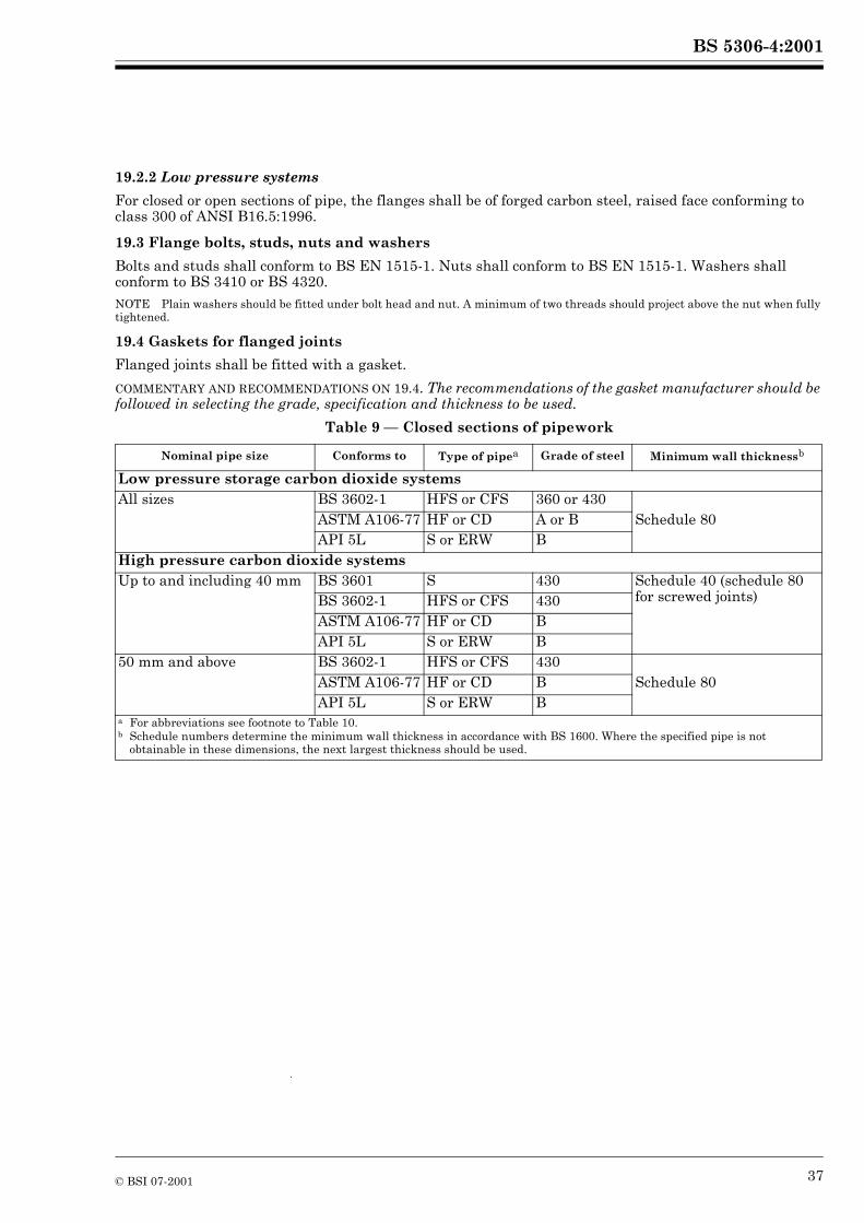
BS 5306-4:2001
19.2.2 Low pressure systems
For closed or open sections of pipe, the flanges shall be of forged carbon steel, raised face conforming to class 300 of ANSI B16.5:1996.
19.3 Flange bolts, studs, nuts and washers
Bolts and studs shall conform to BS EN 1515-1. Nuts shall conform to BS EN 1515-1. Washers shall conform to BS 3410 or BS 4320.NOTE Plain washers should be fitted under bolt head and nut. A minimum of two threads should project above the nut when fully tightened.
19.4 Gaskets for flanged joints
Flanged joints shall be fitted with a gasket.
COMMENTARY AND RECOMMENDATIONS ON 19.4. The recommendations of the gasket manufacturer should be followed in selecting the grade, specification and thickness to be used.
Table 9 — Closed sections of pipework
Nominal pipe size Conforms to Type of pipea Grade of steel Minimum wall thicknessb
Low pressure storage carbon dioxide systemsAll sizes BS 3602-1 HFS or CFS 360 or 430
ASTM A106-77 HF or CD A or B Schedule 80API 5L S or ERW B
High pressure carbon dioxide systemsUp to and including 40 mm BS 3601 S 430 Schedule 40 (schedule 80
for screwed joints)BS 3602-1 HFS or CFS 430ASTM A106-77 HF or CD BAPI 5L S or ERW B
50 mm and above BS 3602-1 HFS or CFS 430ASTM A106-77 HF or CD B Schedule 80API 5L S or ERW B
a For abbreviations see footnote to Table 10.b Schedule numbers determine the minimum wall thickness in accordance with BS 1600. Where the specified pipe is not
obtainable in these dimensions, the next largest thickness should be used.
© BSI 07-2001 37
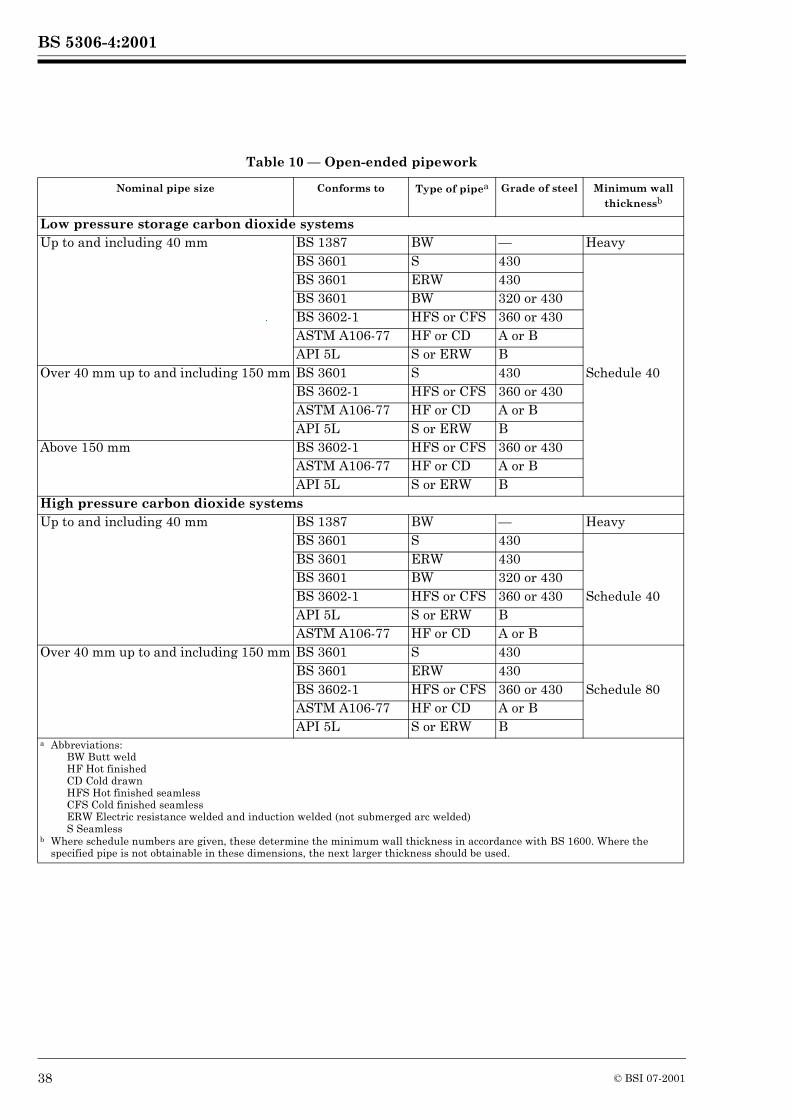
BS 5306-4:2001
Table 10 — Open-ended pipework
Nominal pipe size Conforms to Type of pipea Grade of steel Minimum wall thicknessb
Low pressure storage carbon dioxide systemsUp to and including 40 mm BS 1387 BW — Heavy
BS 3601 S 430BS 3601 ERW 430BS 3601 BW 320 or 430BS 3602-1 HFS or CFS 360 or 430ASTM A106-77 HF or CD A or BAPI 5L S or ERW B
Over 40 mm up to and including 150 mm BS 3601 S 430 Schedule 40BS 3602-1 HFS or CFS 360 or 430ASTM A106-77 HF or CD A or BAPI 5L S or ERW B
Above 150 mm BS 3602-1 HFS or CFS 360 or 430ASTM A106-77 HF or CD A or BAPI 5L S or ERW B
High pressure carbon dioxide systemsUp to and including 40 mm BS 1387 BW — Heavy
BS 3601 S 430BS 3601 ERW 430BS 3601 BW 320 or 430BS 3602-1 HFS or CFS 360 or 430 Schedule 40API 5L S or ERW BASTM A106-77 HF or CD A or B
Over 40 mm up to and including 150 mm BS 3601 S 430BS 3601 ERW 430BS 3602-1 HFS or CFS 360 or 430 Schedule 80ASTM A106-77 HF or CD A or BAPI 5L S or ERW B
a Abbreviations:BW Butt weldHF Hot finishedCD Cold drawnHFS Hot finished seamlessCFS Cold finished seamlessERW Electric resistance welded and induction welded (not submerged arc welded)S Seamless
b Where schedule numbers are given, these determine the minimum wall thickness in accordance with BS 1600. Where the specified pipe is not obtainable in these dimensions, the next larger thickness should be used.
38 © BSI 07-2001
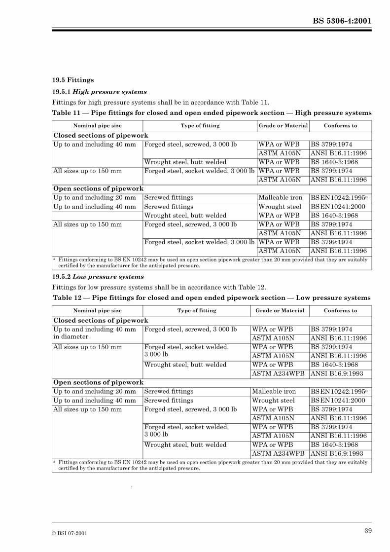
BS 5306-4:2001
19.5 Fittings
19.5.1 High pressure systems
Fittings for high pressure systems shall be in accordance with Table 11.
Table 11 — Pipe fittings for closed and open ended pipework section — High pressure systems
19.5.2 Low pressure systems
Fittings for low pressure systems shall be in accordance with Table 12.
Table 12 — Pipe fittings for closed and open ended pipework section — Low pressure systems
Nominal pipe size Type of fitting Grade or Material Conforms to
Closed sections of pipeworkUp to and including 40 mm Forged steel, screwed, 3 000 lb WPA or WPB BS 3799:1974
ASTM A105N ANSI B16.11:1996Wrought steel, butt welded WPA or WPB BS 1640-3:1968
All sizes up to 150 mm Forged steel, socket welded, 3 000 lb WPA or WPB BS 3799:1974ASTM A105N ANSI B16.11:1996
Open sections of pipeworkUp to and including 20 mm Screwed fittings Malleable iron BSEN10242:1995a
Up to and including 40 mm Screwed fittings Wrought steel BSEN10241:2000Wrought steel, butt welded WPA or WPB BS 1640-3:1968
All sizes up to 150 mm Forged steel, screwed, 3 000 lb WPA or WPB BS 3799:1974ASTM A105N ANSI B16.11:1996
Forged steel, socket welded, 3 000 lb WPA or WPB BS 3799:1974ASTM A105N ANSI B16.11:1996
a Fittings conforming to BS EN 10242 may be used on open section pipework greater than 20 mm provided that they are suitably certified by the manufacturer for the anticipated pressure.
Nominal pipe size Type of fitting Grade or Material Conforms to
Closed sections of pipeworkUp to and including 40 mm in diameter
Forged steel, screwed, 3 000 lb WPA or WPB BS 3799:1974ASTM A105N ANSI B16.11:1996
All sizes up to 150 mm Forged steel, socket welded, 3 000 lb
WPA or WPB BS 3799:1974ASTM A105N ANSI B16.11:1996
Wrought steel, butt welded WPA or WPB BS 1640-3:1968ASTM A234WPB ANSI B16.9:1993
Open sections of pipeworkUp to and including 20 mm Screwed fittings Malleable iron BSEN10242:1995a
Up to and including 40 mm Screwed fittings Wrought steel BSEN10241:2000All sizes up to 150 mm Forged steel, screwed, 3 000 lb WPA or WPB BS 3799:1974
ASTM A105N ANSI B16.11:1996Forged steel, socket welded, 3 000 lb
WPA or WPB BS 3799:1974ASTM A105N ANSI B16.11:1996
Wrought steel, butt welded WPA or WPB BS 1640-3:1968ASTM A234WPB ANSI B16.9:1993
a Fittings conforming to BS EN 10242 may be used on open section pipework greater than 20 mm provided that they are suitably certified by the manufacturer for the anticipated pressure.
© BSI 07-2001 39
BS 5306-4:2001
19.6 Screw threads
Screwed threads shall conform to the dimensions specified in BS 21 or API 5B.
COMMENTARY AND RECOMMENDATIONS ON 19.6. These threads are not compatible and it is recommended that threads of only one type be used on any particular system.
19.7 Flexible hose connections
Flexible hose connections shall conform to BS EN 12094-8.
COMMENTARY AND RECOMMENDATIONS ON 19.7. Where flexible hoses are required to be fitted to low pressure bulk carbon dioxide storage plants or distribution pipework, these should be selected, inspected and tested only by engineers or specialists trained in this field.
20 Installation of pipework
20.1 General
Before final assembly, tubes and fittings shall be inspected visually to ensure that no foreign matter is inside and the full bore is clean. After assembly the system shall be thoroughly blown through with nitrogen or suitable alternative in accordance with 8.1.3.13.
Where carbon dioxide pipes and associated fittings are to be concealed, provision shall be made for access to them at all times.
COMMENTARY AND RECOMMENDATIONS ON 20.1. It is important to ensure that pipework is securely supported, making due allowance for expansion and contraction, particularly in low pressure systems. The contraction in the low pressure system pipework during a discharge due to temperature drop is equivalent to approximately 20 mm for each 30 m length of pipe.
20.2 Protective finish
Stainless steel, copper and copper alloy fittings manufactured in accordance with BS 4368-1 and BS 2051-1 and -2 shall be used where tubes conforming to BS EN 1057 and BS 3605-2 are to be used.
Where corrosion-resistant materials are not used for pipes, fittings or support brackets and steelwork, adequate external protection shall be given against normal corrosion due to atmospheric or local chemical conditions that are likely to affect the materials used.
COMMENTARY AND RECOMMENDATIONS ON 20.2. For low pressure systems, galvanizing of prefabricated pipe sections is recommended wherever possible. It is not suitable, however, in certain atmospheres where chemical fumes, dust or moisture may attack the coating.
Before any protective coating is applied, it is important to prepare metal surfaces to remove all rust, scale, dirt and grease. Surfaces should be free from moisture immediately before the application of the protective medium.
Painted finishes should normally be selected from lead based, zinc-enriched (cold galvanizing) or special paints.
Whichever type is selected, the manufacturer’s recommendations for the particular application should be strictly adhered to (see also 20.1).
20.3 Pipework supports
The maximum distance between supports to take into account the total mass of pipe and carbon dioxide shall be as shown in Table 13.
40 © BSI 07-2001
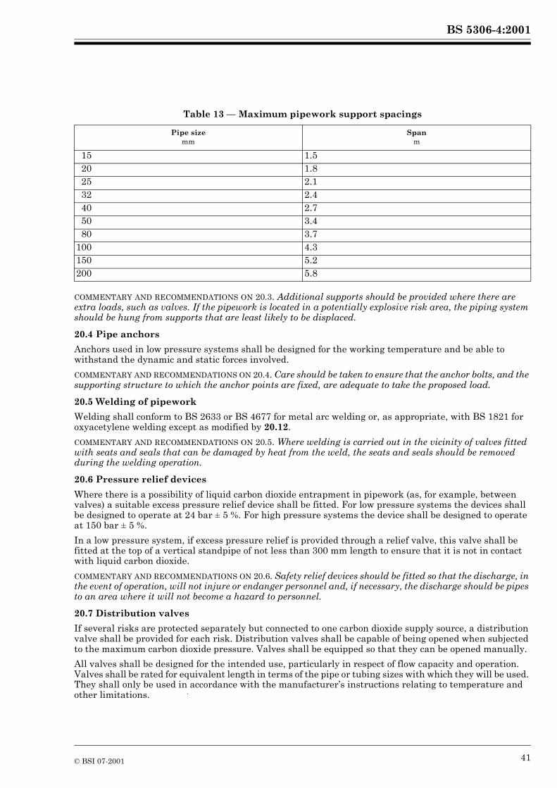
BS 5306-4:2001
Table 13 — Maximum pipework support spacings
COMMENTARY AND RECOMMENDATIONS ON 20.3. Additional supports should be provided where there are extra loads, such as valves. If the pipework is located in a potentially explosive risk area, the piping system should be hung from supports that are least likely to be displaced.
20.4 Pipe anchors
Anchors used in low pressure systems shall be designed for the working temperature and be able to withstand the dynamic and static forces involved.
COMMENTARY AND RECOMMENDATIONS ON 20.4. Care should be taken to ensure that the anchor bolts, and the supporting structure to which the anchor points are fixed, are adequate to take the proposed load.
20.5 Welding of pipework
Welding shall conform to BS 2633 or BS 4677 for metal arc welding or, as appropriate, with BS 1821 for oxyacetylene welding except as modified by 20.12.
COMMENTARY AND RECOMMENDATIONS ON 20.5. Where welding is carried out in the vicinity of valves fitted with seats and seals that can be damaged by heat from the weld, the seats and seals should be removed during the welding operation.
20.6 Pressure relief devices
Where there is a possibility of liquid carbon dioxide entrapment in pipework (as, for example, between valves) a suitable excess pressure relief device shall be fitted. For low pressure systems the devices shall be designed to operate at 24 bar ± 5 %. For high pressure systems the device shall be designed to operate at 150 bar ± 5 %.
In a low pressure system, if excess pressure relief is provided through a relief valve, this valve shall be fitted at the top of a vertical standpipe of not less than 300 mm length to ensure that it is not in contact with liquid carbon dioxide.
COMMENTARY AND RECOMMENDATIONS ON 20.6. Safety relief devices should be fitted so that the discharge, in the event of operation, will not injure or endanger personnel and, if necessary, the discharge should be pipes to an area where it will not become a hazard to personnel.
20.7 Distribution valves
If several risks are protected separately but connected to one carbon dioxide supply source, a distribution valve shall be provided for each risk. Distribution valves shall be capable of being opened when subjected to the maximum carbon dioxide pressure. Valves shall be equipped so that they can be opened manually.
All valves shall be designed for the intended use, particularly in respect of flow capacity and operation. Valves shall be rated for equivalent length in terms of the pipe or tubing sizes with which they will be used. They shall only be used in accordance with the manufacturer’s instructions relating to temperature and other limitations.
Pipe sizemm
Spanm
15 1.520 1.825 2.132 2.440 2.750 3.480 3.7
100 4.3150 5.2200 5.8
© BSI 07-2001 41
BS 5306-4:2001
Valves used in high pressure systems and those that are constantly under pressure shall be designed for a working pressure of 126 bar. The 126 bar working pressure is based on the developed pressure of CO2 at 50 ºC and on a filling density of 0.667 kg/l.
Valves used in low pressure systems shall be designed for a working pressure of 24 bar.
20.8 Discharge nozzles
Discharge nozzles shall be manufactured in corrosion-resistant material and be of adequate strength to withstand expected working temperatures and pressures.
Discharge nozzles shall be permanently marked with the appropriate orifice code number (see Annex E) to show the equivalent single orifice diameter. The markings shall be readily discernible after installation.
Discharge nozzles shall be provided with frangible discs or blow-out caps where clogging by foreign materials is likely. These devices shall provide an unobstructed opening upon system operation.
COMMENTARY AND RECOMMENDATIONS ON 20.8. The discharge nozzle normally consists of the selected orifice and any associated shield or baffle. As the size of the nozzle decreases, so the risk of blockage by dirt increases, and care should be taken to use suitable filters.
20.9 Carbon dioxide pipe and orifice size determination
The design of the piping distribution system shall be based on the flow rate desired at each nozzle.
COMMENTARY AND RECOMMENDATIONS ON 20.9. The problem of computing pipe sizes for carbon dioxide systems is complicated by the fact that the pressure drop is non-linear with respect to the pipeline.
The flow rate desired at each nozzle will determine the required flow rate in the branch lines and the main pipeline. From practical experience, it is possible to estimate the approximate pipe sizes required. The pressure at each nozzle can then be determined from suitable flow curves.
The equations on which flow curves are based, together with derived tables and figures and a detailed discussion of their application, are given in Annex E. Use should be made of these data in the determination of orifice sizes and other details of piping systems.
20.10 Electrical earthing
All exposed metalwork in CO2 systems that are housed within electrical substations or switchrooms shall be efficiently earthed to prevent the metalwork becoming electrically charged.
COMMENTARY AND RECOMMENDATIONS ON 20.10. Adequate earthing of CO2 systems, wherever located, will minimize the risk of electrostatic discharge. BS 5958-1 gives basic information on earthing practice.
20.11 Electrical hazards
Where exposed electrical conductors are present, clearances no smaller than those given in Table 14 shall be provided, where practicable, between the electrical conductors and all parts of the CO2 system that may be approached during maintenance. Where these clearance distances cannot be achieved, warning notices shall be provided and a safe system of maintenance work shall be adopted.
COMMENTARY AND RECOMMENDATIONS ON 20.11. The system should be arranged so that all normal operations can be carried out with safety to the operator.
Where CO2 systems are to be installed in substations or switchrooms, reference should be made to Table 14.
42 © BSI 07-2001
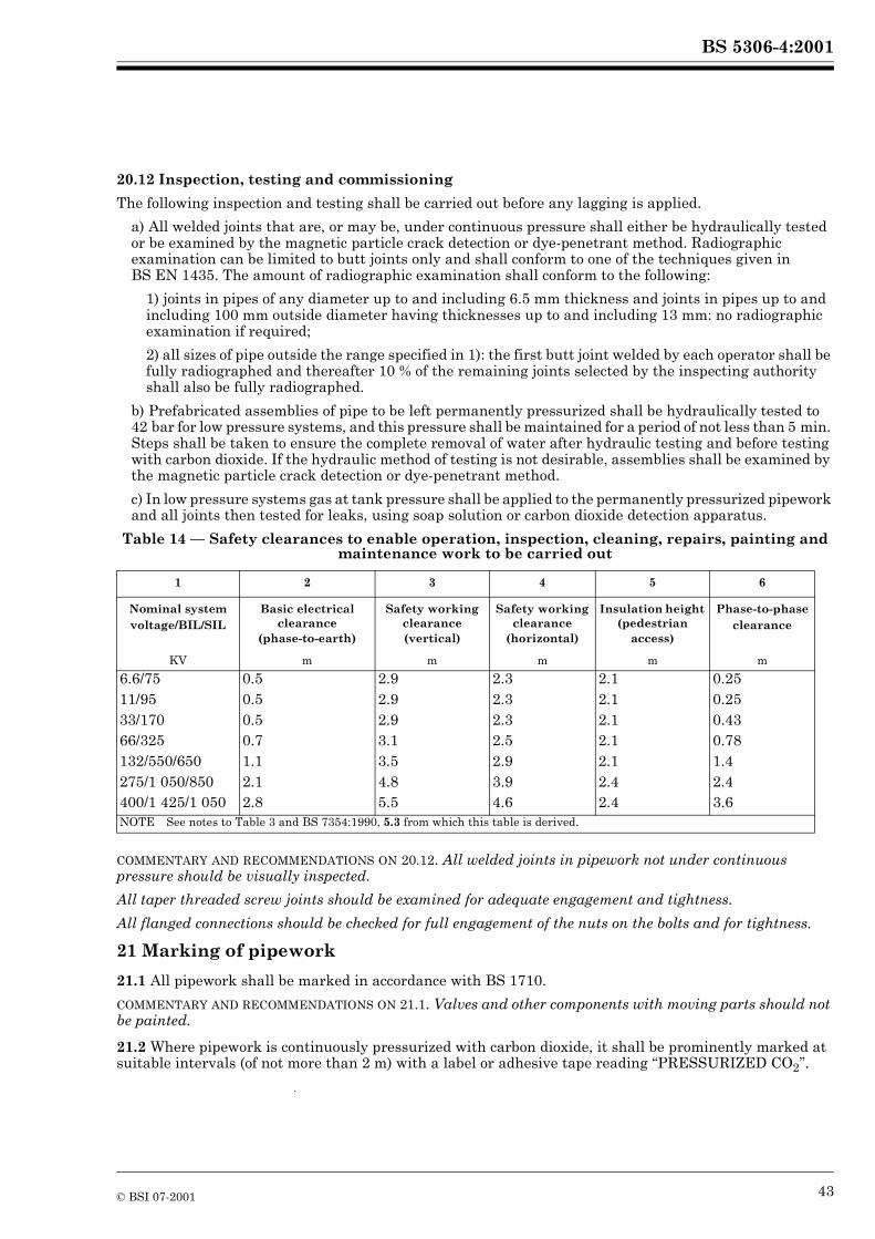
BS 5306-4:2001
20.12 Inspection, testing and commissioning
The following inspection and testing shall be carried out before any lagging is applied.
a) All welded joints that are, or may be, under continuous pressure shall either be hydraulically tested or be examined by the magnetic particle crack detection or dye-penetrant method. Radiographic examination can be limited to butt joints only and shall conform to one of the techniques given in BS EN 1435. The amount of radiographic examination shall conform to the following:
1) joints in pipes of any diameter up to and including 6.5 mm thickness and joints in pipes up to and including 100 mm outside diameter having thicknesses up to and including 13 mm: no radiographic examination if required;
2) all sizes of pipe outside the range specified in 1): the first butt joint welded by each operator shall be fully radiographed and thereafter 10 % of the remaining joints selected by the inspecting authority shall also be fully radiographed.
b) Prefabricated assemblies of pipe to be left permanently pressurized shall be hydraulically tested to 42 bar for low pressure systems, and this pressure shall be maintained for a period of not less than 5 min. Steps shall be taken to ensure the complete removal of water after hydraulic testing and before testing with carbon dioxide. If the hydraulic method of testing is not desirable, assemblies shall be examined by the magnetic particle crack detection or dye-penetrant method.
c) In low pressure systems gas at tank pressure shall be applied to the permanently pressurized pipework and all joints then tested for leaks, using soap solution or carbon dioxide detection apparatus.
Table 14 — Safety clearances to enable operation, inspection, cleaning, repairs, painting and maintenance work to be carried out
COMMENTARY AND RECOMMENDATIONS ON 20.12. All welded joints in pipework not under continuous pressure should be visually inspected.
All taper threaded screw joints should be examined for adequate engagement and tightness.
All flanged connections should be checked for full engagement of the nuts on the bolts and for tightness.
21 Marking of pipework
21.1 All pipework shall be marked in accordance with BS 1710.
COMMENTARY AND RECOMMENDATIONS ON 21.1. Valves and other components with moving parts should not be painted.
21.2 Where pipework is continuously pressurized with carbon dioxide, it shall be prominently marked at suitable intervals (of not more than 2 m) with a label or adhesive tape reading “PRESSURIZED CO2”.
1 2 3 4 5 6
Nominal system voltage/BIL/SIL
Basic electrical clearance
(phase-to-earth)
Safety working clearance (vertical)
Safety working clearance
(horizontal)
Insulation height (pedestrian
access)
Phase-to-phase clearance
KV m m m m m
6.6/75 0.5 2.9 2.3 2.1 0.2511/95 0.5 2.9 2.3 2.1 0.2533/170 0.5 2.9 2.3 2.1 0.4366/325 0.7 3.1 2.5 2.1 0.78132/550/650 1.1 3.5 2.9 2.1 1.4275/1 050/850 2.1 4.8 3.9 2.4 2.4400/1 425/1 050 2.8 5.5 4.6 2.4 3.6NOTE See notes to Table 3 and BS 7354:1990, 5.3 from which this table is derived.
© BSI 07-2001 43
BS 5306-4:2001
Annex A (normative)Door fan test for determination of minimum hold time
A.1 Principle
A fan is temporarily located within an access opening to pressurize and depressurize the enclosure. A series of pressure and air flow measurements is made from which the leakage characteristics of the enclosure are established. The predicted hold time is calculated using these leakage characteristics on the following assumptions:
a) that leakage occurs under the worst conditions, i.e. when one half of the effective leakage area is at the maximum enclosure height and represents the inward leakage of air, and the other half (the lower leakage area) of the total equivalent leakage area is at the lowest point in the enclosure and represents the outward leakage of extinguishant/air;
b) that all leak flow is one-dimensional, i.e. ignoring stream functions;
c) that flow through any particular leak area is either into or out of the enclosure and respectively either from or into an infinitely large space;
d) that the system is at sea-level, at a temperature of 20 ºC, and atmospheric pressure is 1,013 bar absolute.
A.2 Apparatus
A.2.1 Fan unit, consisting of a frame which will fit into and seal an access opening in the enclosure, and one or more variable speed fans, with low flow facilities, capable of giving a differential pressure of not less than 25 Pa across the enclosure boundary.
A.2.2 Two pressure measuring devices, one to measure enclosure differential pressure and one to measure fan flow pressure.
A.2.3 Flexible tubing, for connecting the pressure measuring devices.
A.2.4 Chemical smoke pencils and/or smoke generator.
A.2.5 Two thermometers, to measure ambient temperatures.
A.2.6 Signs, reading “DO NOT OPEN — PRESSURE TEST IN PROGRESS” and “DO NOT CLOSE — PRESSURE TEST IN PROGRESS”.NOTE Additional apparatus, such as measuring tapes, torches, ladders, tools to remove floor and ceiling tiles, computer or other calculating device, may be necessary or convenient.
A.3 Calibration of apparatus
A.3.1 Fan unit
Calibrate the fan unit at the intervals and by the method recommended by the manufacturer. Keep records and where appropriate calibration certificates. Use a flowmeter accurate to ±5 % and a pressure measuring device accurate to ±1 Pa.
A.3.2 Pressure measuring devices
The pressure measuring devices shall be calibrated not more than 12 months before a test. Records and, where appropriate, calibration certificates shall be maintained.
If inclined manometers are used, change the fluid not more than 3 months before the test. Level and zero inclined manometers before each test.
A.4 Preliminary preparation
A.4.1 Obtain a description of air-handling equipment and extinguishant extraction systems in the enclosure from the user.
44 © BSI 07-2001
BS 5306-4:2001
A.4.2 Check for the following:
a) raised platform floors and false ceiling spaces;
b) visually obvious leaks in the enclosure;
c) adequate return paths outside the enclosure between all leaks and the fan unit;
d) conflicting activities in and around the enclosure.
A.4.3 Provide the following information to the user:
a) a description of the test;
b) the time required to complete the test;
c) what assistance will be needed from the user’s staff;
d) information on any necessary disturbance to the building or its services during the test, for example, removal of floor or ceiling tiles, shutdown of air handling systems, holding doors open and/or shut.
A.5 Evaluation of enclosure
Obtain or prepare a sketch plan showing walls, the location of door and other openings through which air will flow during the test, and the location of any ducts penetrating the enclosure, and any dampers in the ducts. Show the status (i.e. whether open or closed when the extinguishant system is discharged) of each door, hatch and damper, and which access opening(s) is (are) to be used for the fan unit.
Show the location of floor and sink drains.
A.6 Measurement of enclosure
Measure the protected enclosure volume as necessary and record the following:
a) the overall height of the protected enclosure, Ho;
b) the height of the highest hazard in the enclosure, H;
c) the gross volume of the protected enclosure, Vg.
A.7 Procedure
A.7.1 Preparation
A.7.1.1 Advise supervisory personnel in the area of the test that the test is about to take place.
A.7.1.2 Remove papers and objects likely to be disturbed by the turbulence from the fan from the test area.
A.7.1.3 Block open sufficient doors outside the enclosure envelope to provide an adequate return path for air between the fan unit and the enclosure leaks while ensuring that requirements for security, fire protection and environmental boundaries of the facility are met.
A.7.1.4 Using the sketch plan (see A.7.6) set all air-handling equipment and extinguishant extraction systems to the state they would be in at the time of extinguishant system discharge, except that:
a) recirculating air-handling equipment without fresh air make-up which does not give a bias pressure across the enclosure boundary or otherwise preclude accurate testing, and which would be shutdown on extinguishant discharge, may be left operating during the test if this is needed to avoid temperature build-up in equipment such as computers; and
b) recirculating air-handling equipment which would continue to operate on extinguishant discharge should be shutdown if it creates excessive bias pressure.
A.7.1.5 Post the appropriate signs on doors (see A.2.6).
A.7.1.6 Open doors and remove floor or ceiling tiles within the extinguishant protected portions of the enclosure envelope so that the extinguishant protected volume is treated as one space. Do not remove false ceiling tiles if the volume above the false ceiling is not protected with extinguishant.
A.7.1.7 Close all doors and windows in the enclosure envelope.
A.7.1.8 Check that liquid traps in the floor and sink drains are sealed with liquid.
© BSI 07-2001 45
BS 5306-4:2001
A.7.2 Setting up the door fan unit
A.7.2.1 Set up the fan unit in an access opening leading from the enclosure into the largest volume of building space which will complete the air-flow path from the fan, via the enclosure, leaks and building space back to the fan.
A.7.2.2 Gently blow into or suck from the flexible tubing so that the readings of the pressure measuring devices traverse the full scale and hold the maximum reading for not less than 10 s.
Release the pressure and zero the devices.
A.7.2.3 Connect the enclosure differential pressure measuring device. Ensure that the open ends of the flexible tubing near the fan unit are away from its air stream path and any other air flows which might affect readings.
A.7.2.4 Use the fan(s) to raise or lower the pressure of the enclosure by approximately 15 Pa. Check all dampers with smoke and ensure that they are closing properly. Check doors and hatches and ensure correct closure. Inspect the wall perimeter (above and below any false floor) and the floor slab for any major leaks and note their size and location.
A.7.3 Measurement of bias pressure
A.7.3.1 Seal the fan unit inlet or outlet and without the fans(s) operating observe the enclosure differential pressure measuring device for at least 30 s.
A.7.3.2 If a bias pressure is indicated, use smoke to detect the consequent air flow and its direction. If the existence of a bias pressure is confirmed record the pressure measuring device reading as the bias pressure (Pb).
A.7.3.3 If the enclosure is large, or if the bias pressure is largely caused by wind or stack effects repeat the measurement at one or more different access openings. Record all the values measured and use the largest positive value (or if only negative values are recorded the value closest to zero) as the bias pressure.NOTE A bias pressure as low as 0,5 Pa can affect the accuracy of the test result. If the bias pressure has a numerical value greater than 25 % of the extinguishant/air column pressure, the hold time is likely to be low and the enclosure may not hold the specified extinguishant concentration. The source of the excessive bias pressure should be identified and if possible permanently reduced.
A.7.4 Measurement of leakage rate
A.7.4.1 Measure the air temperature inside the enclosure Te, and measure the air temperature outside the enclosure To, at several points. If the location of leaks is not known, use the average value; otherwise, use the average value weighted according to the known location of the leaks.
A.7.4.2 Unseal the fan inlet or outlet and connect the fan flow pressure measuring device.
A.7.4.3 Use the fan unit to depressurize the enclosure to the maximum extent, but by not more than 60 Pa. Allow the enclosure differential pressure measuring reading to stabilize (which may take up to 30 s) and record the value (Pf + Pb), which will be negative. Repeat at not less than four more fan unit flow rates to give five readings more or less evenly spaced over the range down to 10 Pa.
A.7.4.4 Use the fan unit to pressurize the enclosure and repeat the procedure of A.7.4.3. Again record value of (Pf + Pb), which will be positive.
A.7.5 Calculation
A.7.5.1 Air flow rates
From the measured values of (Pf + Pb) and Pb calculate the values of Pf and, using the fan calibration data (A.3.1), the corresponding air flows Qf through the fan. Calculate the corrected air flow rates using equations (A.1) and (A.2), as appropriate:
for depressurization:
Ql = Qf (A.1)
Pc1.013--------------- 20 273+
Tc 273+-----------------------�
� � � �
1 2� To 273+Te 273+-----------------------� � � �
1 2�
46 © BSI 07-2001
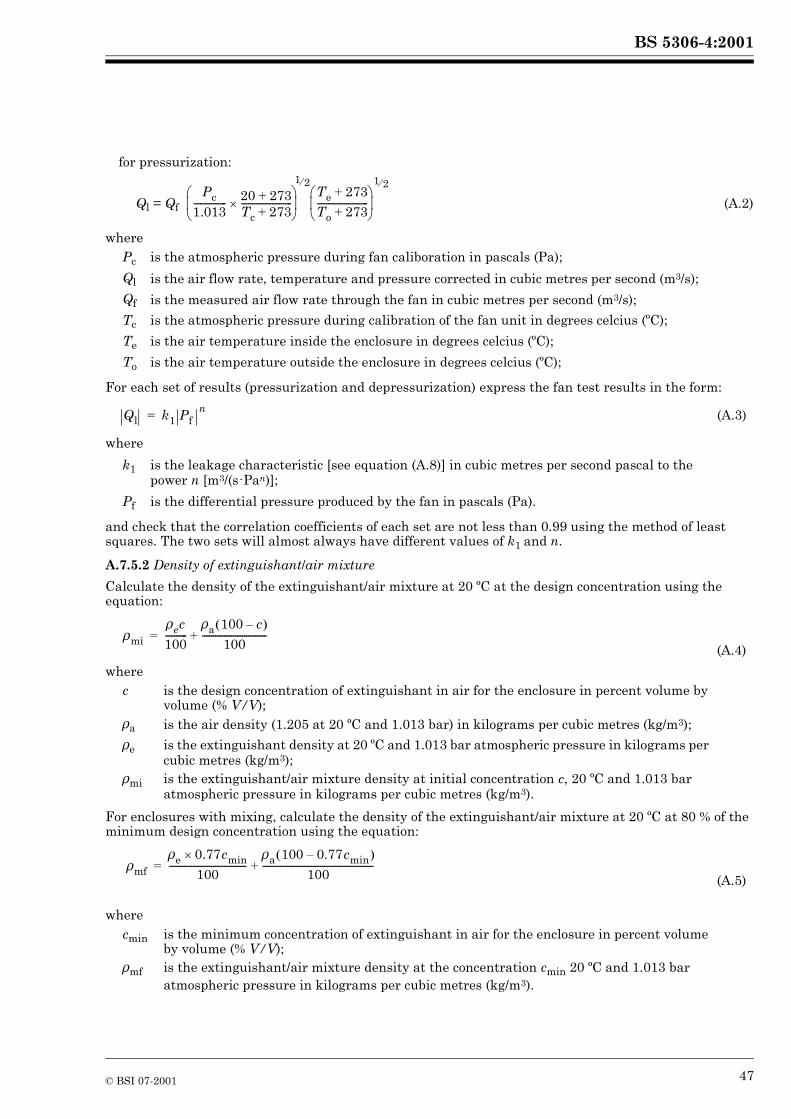
BS 5306-4:2001
for pressurization:
Ql = Qf (A.2)
where
For each set of results (pressurization and depressurization) express the fan test results in the form:
(A.3)
where
and check that the correlation coefficients of each set are not less than 0.99 using the method of least squares. The two sets will almost always have different values of k1 and n.
A.7.5.2 Density of extinguishant/air mixture
Calculate the density of the extinguishant/air mixture at 20 ºC at the design concentration using the equation:
(A.4)
where
For enclosures with mixing, calculate the density of the extinguishant/air mixture at 20 ºC at 80 % of the minimum design concentration using the equation:
(A.5)
where
Pc is the atmospheric pressure during fan caliboration in pascals (Pa);
Ql is the air flow rate, temperature and pressure corrected in cubic metres per second (m3/s);
Qf is the measured air flow rate through the fan in cubic metres per second (m3/s);
Tc is the atmospheric pressure during calibration of the fan unit in degrees celcius (ºC);
Te is the air temperature inside the enclosure in degrees celcius (ºC);
To is the air temperature outside the enclosure in degrees celcius (ºC);
k1 is the leakage characteristic [see equation (A.8)] in cubic metres per second pascal to the power n [m3/(s�Pan)];
Pf is the differential pressure produced by the fan in pascals (Pa).
c is the design concentration of extinguishant in air for the enclosure in percent volume by volume (% V/V);
�a is the air density (1.205 at 20 ºC and 1.013 bar) in kilograms per cubic metres (kg/m3);
�e is the extinguishant density at 20 ºC and 1.013 bar atmospheric pressure in kilograms per cubic metres (kg/m3);
�mi is the extinguishant/air mixture density at initial concentration c, 20 ºC and 1.013 bar atmospheric pressure in kilograms per cubic metres (kg/m3).
cmin is the minimum concentration of extinguishant in air for the enclosure in percent volume by volume (% V/V);
�mf is the extinguishant/air mixture density at the concentration cmin 20 ºC and 1.013 bar atmospheric pressure in kilograms per cubic metres (kg/m3).
Pc1.013--------------- 20 273+
Tc 273+-----------------------�
� � � �
1 2�Te 273+To 273+-----------------------� � � �
1 2�
Ql k1 Pf n=
�mi
�ec
100----------
�a 100 c–� �
100-----------------------------+=
�mf
�e 0.77cmin�
100-----------------------------------
�a 100 0.77cmin–� �
100--------------------------------------------------+=
© BSI 07-2001 47

BS 5306-4:2001
Calculate the corresponding extinguishant air column pressure at the base of the enclosure using the following equation:
(A.6)
where
A.7.5.3 Leakage characteristics
Determine the average values of the leakage characteristics k1 and n, as follows:
(A.7)
(A.8)
where
A.7.5.4 Correlation constant
Calculate the correlation constant k2 using the equation:
(A.9)
where
Calculate the simplifying constant k3 using the equation:
(A.10)
where
Calculate the simplifying constant k4 using the equation:
(A.11)
where
Pm is the CO2/air column pressure in pascals (Pa);gn is the gravitational acceleration (= 9.81) in metres per second squared (m/s2);Ho is the overall height of the enclosure in metres (m);
n is the leakage characteristic (dimensionless);Pmi is the initial CO2/air column pressure in pascals (Pa);
Qlm is the mean value of Ql at Pf = Pm in cubic metres per second (m3/s).
k2 is the correlation constant in kgn�m3(1-n)/(s�Pan);
k3 is the simplifying constant in metres per second squared (m/s2);
F is the lower leakage fraction, effective area of lower leaks divided by effective area of all leaks (dimensionless).
k4 is the simplifying constant in Pa�m3/kg;
Pb is the bias pressure in pascals (Pa).
Pm gnHo �mi �a–� �=
n1nQlm 1nQlm 2�–� �
ln2-----------------------------------------------------=
k1 exp lnQlm 2�� � lnPmi� � lnQlm� � lnPmi ln2–� �–
ln2------------------------------------------------------------------------------------------------------------------
�� �� �
=
k2 k1
�a2------� �� �
n=
k3
2gn �mi �a–� �
�mi �aF
1 F–-------------� �� � 1/n
+------------------------------------------------=
k4
2Pb
�mi �aF
1 F–-------------� �� �1/n+
------------------------------------------------=
48 © BSI 07-2001
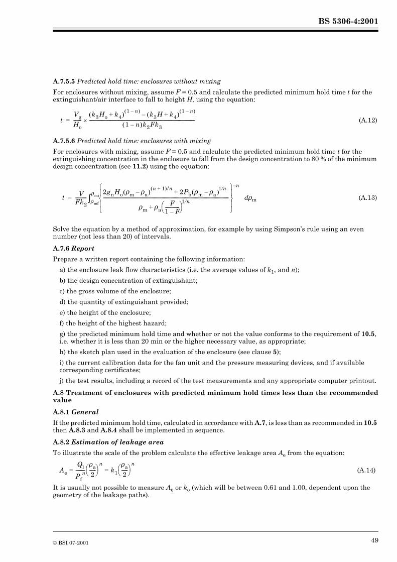
BS 5306-4:2001
A.7.5.5 Predicted hold time: enclosures without mixing
For enclosures without mixing, assume F = 0.5 and calculate the predicted minimum hold time t for the extinguishant/air interface to fall to height H, using the equation:
(A.12)
A.7.5.6 Predicted hold time: enclosures with mixing
For enclosures with mixing, assume F = 0.5 and calculate the predicted minimum hold time t for the extinguishing concentration in the enclosure to fall from the design concentration to 80 % of the minimum design concentration (see 11.2) using the equation:
d�m (A.13)
Solve the equation by a method of approximation, for example by using Simpson’s rule using an even number (not less than 20) of intervals.
A.7.6 Report
Prepare a written report containing the following information:
a) the enclosure leak flow characteristics (i.e. the average values of k1, and n);
b) the design concentration of extinguishant;
c) the gross volume of the enclosure;
d) the quantity of extinguishant provided;
e) the height of the enclosure;
f) the height of the highest hazard;
g) the predicted minimum hold time and whether or not the value conforms to the requirement of 10.5, i.e. whether it is less than 20 min or the higher necessary value, as appropriate;
h) the sketch plan used in the evaluation of the enclosure (see clause 5);
i) the current calibration data for the fan unit and the pressure measuring devices, and if available corresponding certificates;
j) the test results, including a record of the test measurements and any appropriate computer printout.
A.8 Treatment of enclosures with predicted minimum hold times less than the recommendedvalue
A.8.1 General
If the predicted minimum hold time, calculated in accordance with A.7, is less than as recommended in 10.5 then A.8.3 and A.8.4 shall be implemented in sequence.
A.8.2 Estimation of leakage area
To illustrate the scale of the problem calculate the effective leakage area Ae from the equation:
(A.14)
It is usually not possible to measure Ae or ko (which will be between 0.61 and 1.00, dependent upon the geometry of the leakage paths).
tVgHo-------
k3Ho k4+� �1 n–� � k3H k4+� �
1 n–� �–1 n–� �k2Fk3
-----------------------------------------------------------------------------------------------�=
t VFk2----------
2gnHo �m �a–� �n 1+� � /n 2Pb �m �a–� �
1 n�+
�m �aF
1 F–-------------� �� �+
1 n�-----------------------------------------------------------------------------------------------------------------
�� �� �� �� � n–
�mf
�mi�=
Ae
Q1
Pfn--------
�a2------� �� �=
nk1
�a2------� �� �=
n
© BSI 07-2001 49
BS 5306-4:2001
A.8.3 Improved sealing of the enclosure
Consideration shall be given to improving the sealing of the enclosure. If the sealing is improved and the new predicted minimum hold time is not less than the minimum recommended value, no further action shall be taken.
A.8.4 Quantification and location of leaksNOTE The lower leaks are those through which the extinguishant/air mixture will escape from the enclosure; conversely upper leaks are those through which air will flow into the enclosure. For the purposes of this assessment lower leaks are assumed to be those below the height of the highest hazard, H, and upper leaks those above.
The fan test does not show the location of the leaks or the value of the lower leakage fraction F. In A.7.5.5 and A.7.5.6 it is assumed that the value of F is 0.5, with all the lower leaks in the base of the enclosure and that all the upper leaks (equal in area to the lower leaks) are in the top of the enclosure. This is the worst case and gives the minimum value for hold time.
If some lower leaks are above the base of the enclosure or if some upper leaks are below the top of the enclosure, the hold time will also be underestimated but a simple mathematical treatment of this case is not possible.
The hold time will also be underestimated if F is not 0.5 and the effect of this can be calculated.
A.8.4.1 Second calculation of hold time
Conduct a second calculation of the hold time using equations (A.8), (A.9) and (A.10) or equation (A.11), as appropriate, assuming F = 0.15. If this value is more than the recommended minimum (see 10.4.1 and 10.5) make an estimate of the actual value of F using one or both of the methods of A.8.4.2.
A.8.4.2 Methods of estimating F
A.8.4.2.1 First method
Temporarily seal known or suspected leaks, such as large dampers, or suspended ceilings or raised floors using for example plastics sheet and sealing tape, and carry out additional fan tests. Calculate the effective leakage area from equation (A.12) and compare with the original value (see A.8.2) and estimate F for the original condition.
A.8.4.2.2 Second method
Make a detailed inspection of the enclosure using chemical smoke to establish that there are no significant lower leaks and that there are substantial upper leaks, and estimate F.
A.8.4.2.3 Final calculation of hold time
Using the value of F estimated as in A.8.4.2, which should not be more than 0.5 or less than 0.15, recalculate the hold time using equations (A.8), (A.9) and (A.10) or equation (A.11) as appropriate.
Annex B (informative)Service schedule
An example of a suitable service schedule is as follows.
a) Every 3 months Test and service all electrical detection and alarm systems.b) Every 6 months Perform the following checks and inspections.
1) Externally examine pipework to determine its condition. Replace or pressure test and repair as necessary pipework showing corrosion or mechanical damage.2) Check all control valves for correct manual function and automatic valves additionally for correct automatic function.3) Externally examine containers for signs of damage or unauthorized modification, and for damage to system hoses.4) Check contents of pilot containers. Liquefied gas type should be within 10 % and non-liquefied within 5 % of correct charge. Replace or refill any showing a greater loss.5) Carbon dioxide containers, check weigh or use a liquid level indicator to verify correct content of containers. Replace or refill any showing a loss of more than 10 %.
c) Every 12 months Carry out a check of enclosure integrity using the method given in Annex A. If the measured aggregate area of leakage has increased from that measured during installation which would adversely affect system performance, carry out work to reduce the leakage.d) As required by BS 5430, but otherwise when convenient, remove the containers and pressure test when necessary.
50 © BSI 07-2001
BS 5306-4:2001
Annex C (normative)Determination of carbon dioxide concentrations for flammable liquids and gases
C.1 Principle
The minimum requirements for determining the flame extinguishing concentration of a gaseous extinguishant in air for flammable liquids and gases employing the cup burner apparatus are set out. Diffusion flames of fuels burning in a round reservoir (cup) centrally positioned in a coaxially flowing air stream are extinguished by addition of a gaseous extinguishant to the air.
C.2 Apparatus
C.2.1 General
The cup burner apparatus for determining the flame extinguishing concentration of a gaseous extinguishant in air for flammable liquids and gases shall be arranged and constructed as in Figure C.1, employing the dimensions shown; the tolerance for all dimensions shall be ±5 % unless otherwise indicated.
C.2.2 Cup, round, constructed of glass, quartz or steel, having an outside diameter in the range of 28 mm to 31 mm, with a wall thickness of 1–2 mm and a 45º chamfer ground into the top edge. The cup shall have an internal means of temperature measurement of the fuel at a location of 2 mm to 5 mm below its top, and a means of heating the fuel. A cup intended for use with gaseous fuels shall have a means of attaining a uniform gas flow at the top of the cup (e.g. the cup may be packed with refractory materials).
C.2.3 Chimney, of round glass or quartz construction, having an inside diameter of 85 mm ± 2 mm, a wall thickness of 2 mm to 5 mm and a height of 533 mm.
C.2.4 Diffuser, with a means of fitting to the bottom end of the chimney and a means of admitting a premixed stream of air and extinguishant. The diffuser shall have a means of uniformly distributing the air-extinguishant flow across the cross-section of the chimney.
C.2.5 Fuel supply (liquids), capable of delivering liquid fuel to the cup while maintaining a fixed, but adjustable, liquid level therein.
C.2.6 Fuel supply (gases), capable of delivering the fuel at a controlled and fixed rate to the cup.
C.2.7 Manifold, capable of receiving air and extinguishant and delivering them as a single mixed stream to the diffuser.
C.2.8 Air supply, for delivering air to the manifold which allows adjustment of the air flow rate and has a calibrated means of measuring the air flow rate.
C.2.9 Extinguishant supply, for delivering extinguishant to the manifold which allows adjustment of the extinguishant flow rate and has a calibrated means of measuring the extinguishant flow rate.
C.2.10 Delivery system, capable of delivering a representative and measurable sample of the agent to the cup burner in gaseous form.
C.3 Materials
C.3.1 Air, clean, dry and oil-free. The oxygen concentration shall be 20.9 ± 0.5 % v/v. The source and oxygen content of the air employed shall be recorded.NOTE Air supplied in commercial high-pressure cylinders may have an oxygen content significantly different from 20.9 % v/v.
C.3.2 Fuel, of a certified type and quality.
C.3.3 Extinguishant, of certified type which meets the specifications of the supplier. NOTE CO2 which meets the requirements of EN 25923.
C.4 Procedure, flammable liquids
C.4.1 Place the flammable liquid in the fuel supply reservoir.
C.4.2 Admit fuel to the cup adjusting the liquid level to within 5 mm to 10 mm of the top of the cup.
© BSI 07-2001 51
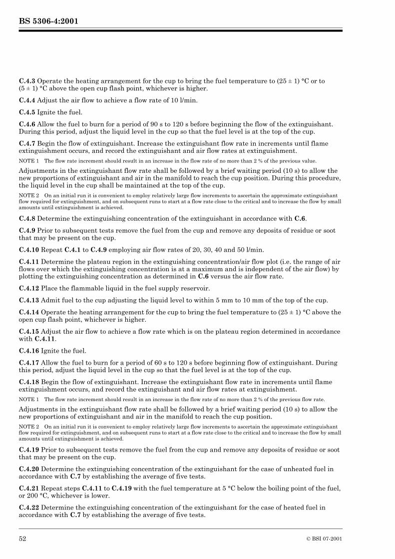
BS 5306-4:2001
C.4.3 Operate the heating arrangement for the cup to bring the fuel temperature to (25 ± 1) °C or to (5 ± 1) °C above the open cup flash point, whichever is higher.
C.4.4 Adjust the air flow to achieve a flow rate of 10 l/min.
C.4.5 Ignite the fuel.
C.4.6 Allow the fuel to burn for a period of 90 s to 120 s before beginning the flow of the extinguishant. During this period, adjust the liquid level in the cup so that the fuel level is at the top of the cup.
C.4.7 Begin the flow of extinguishant. Increase the extinguishant flow rate in increments until flame extinguishment occurs, and record the extinguishant and air flow rates at extinguishment. NOTE 1 The flow rate increment should result in an increase in the flow rate of no more than 2 % of the previous value.
Adjustments in the extinguishant flow rate shall be followed by a brief waiting period (10 s) to allow the new proportions of extinguishant and air in the manifold to reach the cup position. During this procedure, the liquid level in the cup shall be maintained at the top of the cup.NOTE 2 On an initial run it is convenient to employ relatively large flow increments to ascertain the approximate extinguishant flow required for extinguishment, and on subsequent runs to start at a flow rate close to the critical and to increase the flow by small amounts until extinguishment is achieved.
C.4.8 Determine the extinguishing concentration of the extinguishant in accordance with C.6.
C.4.9 Prior to subsequent tests remove the fuel from the cup and remove any deposits of residue or soot that may be present on the cup.
C.4.10 Repeat C.4.1 to C.4.9 employing air flow rates of 20, 30, 40 and 50 l/min.
C.4.11 Determine the plateau region in the extinguishing concentration/air flow plot (i.e. the range of air flows over which the extinguishing concentration is at a maximum and is independent of the air flow) by plotting the extinguishing concentration as determined in C.6 versus the air flow rate.
C.4.12 Place the flammable liquid in the fuel supply reservoir.
C.4.13 Admit fuel to the cup adjusting the liquid level to within 5 mm to 10 mm of the top of the cup.
C.4.14 Operate the heating arrangement for the cup to bring the fuel temperature to (25 ± 1) °C above the open cup flash point, whichever is higher.
C.4.15 Adjust the air flow to achieve a flow rate which is on the plateau region determined in accordance with C.4.11.
C.4.16 Ignite the fuel.
C.4.17 Allow the fuel to burn for a period of 60 s to 120 s before beginning flow of extinguishant. During this period, adjust the liquid level in the cup so that the fuel level is at the top of the cup.
C.4.18 Begin the flow of extinguishant. Increase the extinguishant flow rate in increments until flame extinguishment occurs, and record the extinguishant and air flow rates at extinguishment. NOTE 1 The flow rate increment should result in an increase in the flow rate of no more than 2 % of the previous flow rate.
Adjustments in the extinguishant flow rate shall be followed by a brief waiting period (10 s) to allow the new proportions of extinguishant and air in the manifold to reach the cup position.NOTE 2 On an initial run it is convenient to employ relatively large flow increments to ascertain the approximate extinguishant flow required for extinguishment, and on subsequent runs to start at a flow rate close to the critical and to increase the flow by small amounts until extinguishment is achieved.
C.4.19 Prior to subsequent tests remove the fuel from the cup and remove any deposits of residue or soot that may be present on the cup.
C.4.20 Determine the extinguishing concentration of the extinguishant for the case of unheated fuel in accordance with C.7 by establishing the average of five tests.
C.4.21 Repeat steps C.4.11 to C.4.19 with the fuel temperature at 5 °C below the boiling point of the fuel, or 200 °C, whichever is lower.
C.4.22 Determine the extinguishing concentration of the extinguishant for the case of heated fuel in accordance with C.7 by establishing the average of five tests.
52 © BSI 07-2001
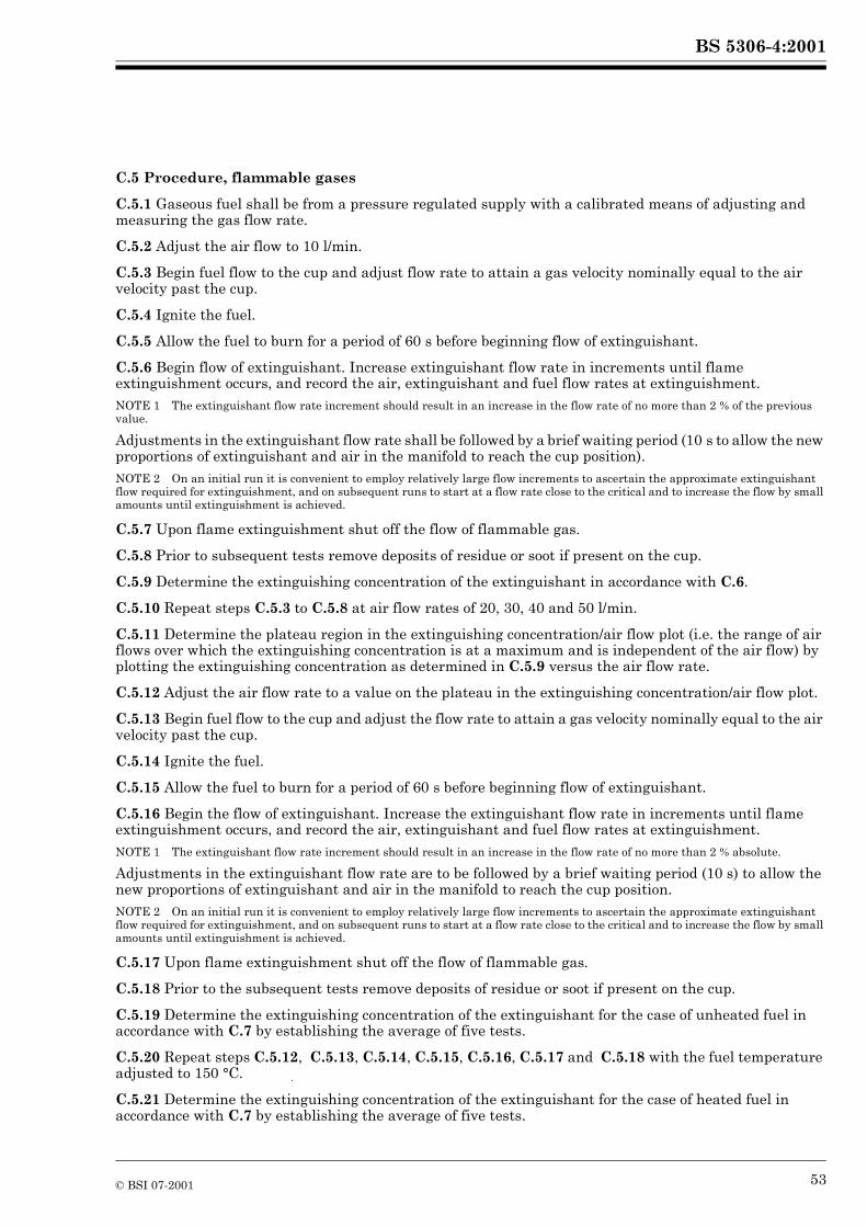
BS 5306-4:2001
C.5 Procedure, flammable gases
C.5.1 Gaseous fuel shall be from a pressure regulated supply with a calibrated means of adjusting and measuring the gas flow rate.
C.5.2 Adjust the air flow to 10 l/min.
C.5.3 Begin fuel flow to the cup and adjust flow rate to attain a gas velocity nominally equal to the air velocity past the cup.
C.5.4 Ignite the fuel.
C.5.5 Allow the fuel to burn for a period of 60 s before beginning flow of extinguishant.
C.5.6 Begin flow of extinguishant. Increase extinguishant flow rate in increments until flame extinguishment occurs, and record the air, extinguishant and fuel flow rates at extinguishment. NOTE 1 The extinguishant flow rate increment should result in an increase in the flow rate of no more than 2 % of the previous value.
Adjustments in the extinguishant flow rate shall be followed by a brief waiting period (10 s to allow the new proportions of extinguishant and air in the manifold to reach the cup position). NOTE 2 On an initial run it is convenient to employ relatively large flow increments to ascertain the approximate extinguishant flow required for extinguishment, and on subsequent runs to start at a flow rate close to the critical and to increase the flow by small amounts until extinguishment is achieved.
C.5.7 Upon flame extinguishment shut off the flow of flammable gas.
C.5.8 Prior to subsequent tests remove deposits of residue or soot if present on the cup.
C.5.9 Determine the extinguishing concentration of the extinguishant in accordance with C.6.
C.5.10 Repeat steps C.5.3 to C.5.8 at air flow rates of 20, 30, 40 and 50 l/min.
C.5.11 Determine the plateau region in the extinguishing concentration/air flow plot (i.e. the range of air flows over which the extinguishing concentration is at a maximum and is independent of the air flow) by plotting the extinguishing concentration as determined in C.5.9 versus the air flow rate.
C.5.12 Adjust the air flow rate to a value on the plateau in the extinguishing concentration/air flow plot.
C.5.13 Begin fuel flow to the cup and adjust the flow rate to attain a gas velocity nominally equal to the air velocity past the cup.
C.5.14 Ignite the fuel.
C.5.15 Allow the fuel to burn for a period of 60 s before beginning flow of extinguishant.
C.5.16 Begin the flow of extinguishant. Increase the extinguishant flow rate in increments until flame extinguishment occurs, and record the air, extinguishant and fuel flow rates at extinguishment. NOTE 1 The extinguishant flow rate increment should result in an increase in the flow rate of no more than 2 % absolute.
Adjustments in the extinguishant flow rate are to be followed by a brief waiting period (10 s) to allow the new proportions of extinguishant and air in the manifold to reach the cup position. NOTE 2 On an initial run it is convenient to employ relatively large flow increments to ascertain the approximate extinguishant flow required for extinguishment, and on subsequent runs to start at a flow rate close to the critical and to increase the flow by small amounts until extinguishment is achieved.
C.5.17 Upon flame extinguishment shut off the flow of flammable gas.
C.5.18 Prior to the subsequent tests remove deposits of residue or soot if present on the cup.
C.5.19 Determine the extinguishing concentration of the extinguishant for the case of unheated fuel in accordance with C.7 by establishing the average of five tests.
C.5.20 Repeat steps C.5.12, C.5.13, C.5.14, C.5.15, C.5.16, C.5.17 and C.5.18 with the fuel temperature adjusted to 150 °C.
C.5.21 Determine the extinguishing concentration of the extinguishant for the case of heated fuel in accordance with C.7 by establishing the average of five tests.
© BSI 07-2001 53
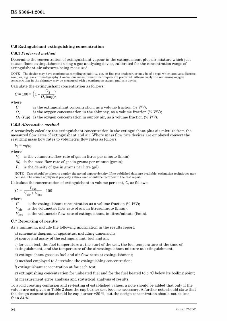
BS 5306-4:2001
54 © BSI 07-2001
C.6 Extinguishant extinguishing concentration
C.6.1 Preferred method
Determine the concentration of extinguishant vapour in the extinguishant plus air mixture which just causes flame extinguishment using a gas analysing device, calibrated for the concentration range of extinguishant-air mixtures being measured. NOTE The device may have continuous sampling capability, e.g. on line gas analyser, or may be of a type which analyses discrete samples, e.g. gas chromatography. Continuous measurement techniques are preferred. Alternatively the remaining oxygen concentration in the chimney may be measured with a continuous oxygen analysis device.
Calculate the extinguishant concentration as follows:
C = 100 ���
where
C.6.2 Alternative method
Alternatively calculate the extinguishant concentration in the extinguishant plus air mixture from the measured flow rates of extinguishant and air. Where mass flow rate devices are employed convert the resulting mass flow rates to volumetric flow rates as follows:
Vi = mi/pi
where
NOTE Care should be taken to employ the actual vapour density. If no published data are available, estimation techniques may be used. The source of physical property values used should be recorded in the test report.
Calculate the concentration of extinguishant in volume per cent, C, as follows:
where
C.7 Reporting of results
As a minimum, include the following information in the results report:
a) schematic diagram of apparatus, including dimensions;b) source and assay of the extinguishant, fuel and air;
c) for each test, the fuel temperature at the start of the test, the fuel temperature at the time of extinguishment, and the temperature of the air/extinguishant mixture at extinguishment;
d) extinguishant gaseous fuel and air flow rates at extinguishment;
e) method employed to determine the extinguishing concentration;
f) extinguishant concentration at for each test;
g) extinguishing concentration for unheated fuel and for the fuel heated to 5 °C below its boiling point;
h) measurement error analysis and statistical analysis of results.
To avoid creating confusion and re-testing of established values, a note should be added that only if the values are not given in Table 2 does the cup burner test become necessary. A further note should state that the design concentration should be cup burner +20 %, but the design concentration should not be less than 34 %.
C is the extinguishant concentration, as a volume fraction (% V/V);O2 is the oxygen concentration in the chimney, as a volume fraction (% V/V);O2 (sup) is the oxygen concentration in supply air, as a volume fraction (% V/V).
Vi is the volumetric flow rate of gas in litres per minute (l/min);Mi is the mass flow rate of gas in grams per minute (g/min);Pi is the density of gas in grams per litre (g/l).
C is the extinguishant concentration as a volume fraction (% V/V);Vair is the volumetric flow rate of air, in litres/minute (l/min);Vext is the volumetric flow rate of extinguishant, in litres/minute (l/min).
1O2
O2(sup)---------------------–� �
� �
CVext
Vair Vext+---------------------------- 100–=
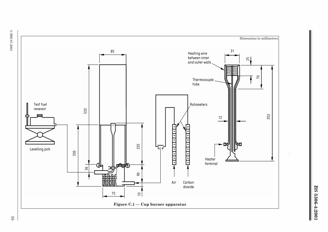
BS
5306-4:2001
Dimensions in millimetres
31
25
2
Heater terminal
12
25
70
eeralls
ouple
s
© B
SI 07-2001
55
Figure C.1 — Cup burner apparatus
85
53
3
33
0
23
59
0
36
75 10
Test fuelresevoir
Air Carbon dioxide
Heating wirbetween innand outer w
Thermoctube
Rotameter
Levelling jack
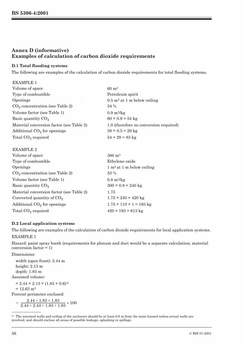
BS 5306-4:2001
Annex D (informative)Examples of calculation of carbon dioxide requirements
D.1 Total flooding systems
The following are examples of the calculation of carbon dioxide requirements for total flooding systems.
D.2 Local application systems
The following are examples of the calculation of carbon dioxide requirements for local application systems.
EXAMPLE 1
Hazard: paint spray booth (requirements for plenum and duct would be a separate calculation; material conversion factor = 1)
Dimensions:
width (open front): 2.44 mheight: 2.13 mdepth: 1.83 m
Assumed volume:
= 2.44 � 2.13 � (1.83 + 0.6)1)
= 12.63 m3
Percent perimeter enclosed:
EXAMPLE 1Volume of space 60 m3
Type of combustible Petroleum spiritOpenings 0.5 m2 at 1 m below ceilingCO2 concentration (see Table 2) 34 %
Volume factor (see Table 1) 0.9 m3/kgBasic quantity CO2 60 � 0.9 = 54 kg
Material conversion factor (see Table 2) 1.0 (therefore no conversion required)Additional CO2 for openings 58 � 0.5 = 29 kg
Total CO2 required 54 + 29 = 83 kg
EXAMPLE 2Volume of space 300 m3
Type of combustible Ethylene oxideOpenings 1 m2 at 1 m below ceiling CO2 concentration (see Table 2) 53 %
Volume factor (see Table 1) 0.8 m3/kgBasic quantity CO2 300 � 0.8 = 240 kg
Material conversion factor (see Table 2) 1.75Converted quantity of CO2 1.75 � 240 = 420 kg
Additional CO2 for openings 1.75 � 110 � 1 = 193 kg
Total CO2 required 420 + 193 = 613 kg
1) The assumed walls and ceiling of the enclosure should be at least 0.6 m from the main hazard unless actual walls are involved, and should enclose all areas of possible leakage, splashing or spillage.
2.44 1.83 1.83+ +2.44 2.44 1.83 1.83+ + +----------------------------------------------------------------- 100�=
56 © BSI 07-2001
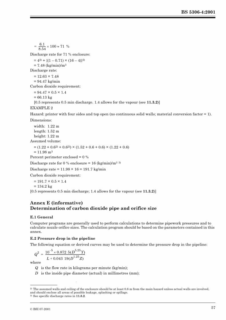
BS 5306-4:2001
%
Discharge rate for 71 % enclosure:
= 42) + {(1 – 0.71) � (16 – 4)}2)
= 7.48 (kg/min)/m3
Discharge rate:
= 12.63 � 7.48= 94.47 kg/min
Carbon dioxide requirement:
= 94.47 � 0.5 � 1.4= 66.13 kg[0.5 represents 0.5 min discharge. 1.4 allows for the vapour (see 11.3.2)]
EXAMPLE 2
Hazard: printer with four sides and top open (no continuous solid walls; material conversion factor = 1).
Dimensions:
width: 1.22 mlength: 1.52 mheight: 1.22 m
Assumed volume:
= (1.22 + 0.62) + 0.62)) � (1.52 + 0.6 + 0.6) � (1.22 + 0.6)= 11.98 m3
Percent perimeter enclosed = 0 %
Discharge rate for 0 % enclosure = 16 (kg/min)/m3 3)
Discharge rate = 11.98 � 16 = 191.7 kg/min
Carbon dioxide requirement:
= 191.7 � 0.5 � 1.4= 134.2 kg
[0.5 represents 0.5 min discharge; 1.4 allows for the vapour (see 11.3.2)]
Annex E (informative)Determination of carbon dioxide pipe and orifice size
E.1 General
Computer programs are generally used to perform calculations to determine pipework pressures and to calculate nozzle orifice sizes. The calculation program should be based on the parameters contained in this annex.
E.2 Pressure drop in the pipeline
The following equation or derived curves may be used to determine the pressure drop in the pipeline:
where
2) The assumed walls and ceiling of the enclosure should be at least 0.6 m from the main hazard unless actual walls are involved, and should enclose all areas of possible leakage, splashing or spillage.3) See specific discharge rates in 11.8.2.
Q is the flow rate in kilograms per minute (kg/min);D is the inside pipe diameter (actual) in millimetres (mm);
6.18.54----------- 100 71��=
Q2 10 5– 0.872 5 D5.25Y� ��
L 0.043 19 D1.25Z� �+---------------------------------------------------------------=
© BSI 07-2001 57
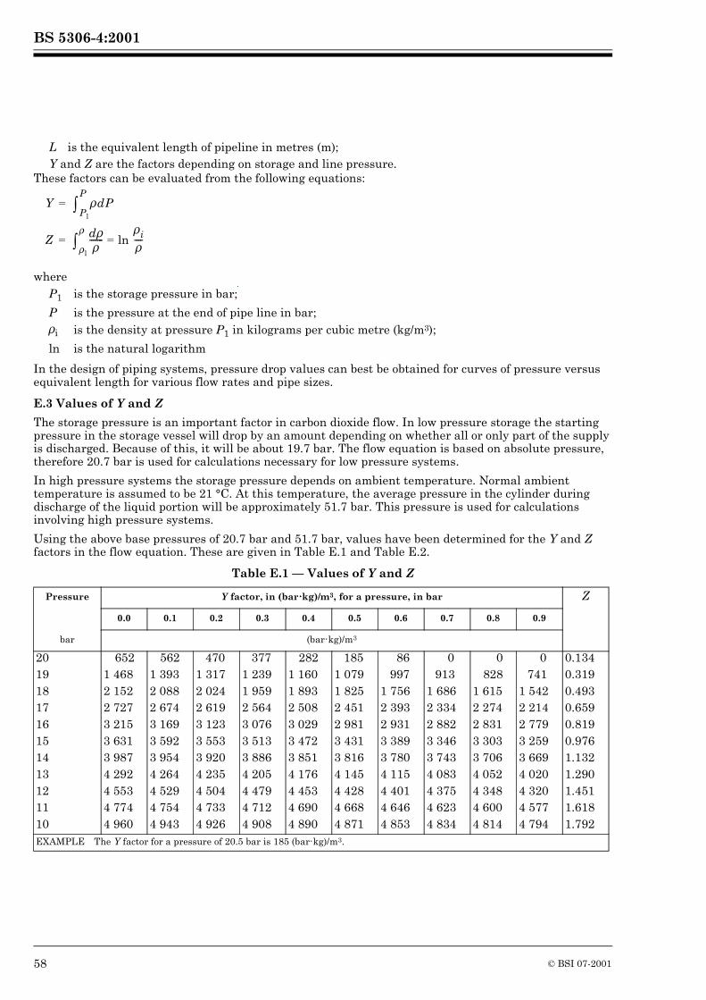
BS 5306-4:2001
These factors can be evaluated from the following equations:
where
In the design of piping systems, pressure drop values can best be obtained for curves of pressure versus equivalent length for various flow rates and pipe sizes.
E.3 Values of Y and Z
The storage pressure is an important factor in carbon dioxide flow. In low pressure storage the starting pressure in the storage vessel will drop by an amount depending on whether all or only part of the supply is discharged. Because of this, it will be about 19.7 bar. The flow equation is based on absolute pressure, therefore 20.7 bar is used for calculations necessary for low pressure systems.
In high pressure systems the storage pressure depends on ambient temperature. Normal ambient temperature is assumed to be 21 °C. At this temperature, the average pressure in the cylinder during discharge of the liquid portion will be approximately 51.7 bar. This pressure is used for calculations involving high pressure systems.
Using the above base pressures of 20.7 bar and 51.7 bar, values have been determined for the Y and Z factors in the flow equation. These are given in Table E.1 and Table E.2.
Table E.1 — Values of Y and Z
L is the equivalent length of pipeline in metres (m);Y and Z are the factors depending on storage and line pressure.
P1 is the storage pressure in bar;
P is the pressure at the end of pipe line in bar;�i is the density at pressure P1 in kilograms per cubic metre (kg/m3);
ln is the natural logarithm
Pressure Y factor, in (bar����kg)/m3, for a pressure, in bar Z
0.0 0.1 0.2 0.3 0.4 0.5 0.6 0.7 0.8 0.9
bar (bar�kg)/m3
20 652 562 470 377 282 185 86 0 0 0 0.13419 1 468 1 393 1 317 1 239 1 160 1 079 997 913 828 741 0.31918 2 152 2 088 2 024 1 959 1 893 1 825 1 756 1 686 1 615 1 542 0.49317 2 727 2 674 2 619 2 564 2 508 2 451 2 393 2 334 2 274 2 214 0.65916 3 215 3 169 3 123 3 076 3 029 2 981 2 931 2 882 2 831 2 779 0.81915 3 631 3 592 3 553 3 513 3 472 3 431 3 389 3 346 3 303 3 259 0.97614 3 987 3 954 3 920 3 886 3 851 3 816 3 780 3 743 3 706 3 669 1.13213 4 292 4 264 4 235 4 205 4 176 4 145 4 115 4 083 4 052 4 020 1.29012 4 553 4 529 4 504 4 479 4 453 4 428 4 401 4 375 4 348 4 320 1.45111 4 774 4 754 4 733 4 712 4 690 4 668 4 646 4 623 4 600 4 577 1.61810 4 960 4 943 4 926 4 908 4 890 4 871 4 853 4 834 4 814 4 794 1.792EXAMPLE The Y factor for a pressure of 20.5 bar is 185 (bar�kg)/m3.
Y � Pl
P
� dP=
Z d��
------- ln �i�----=
�l
�
�=
58 © BSI 07-2001
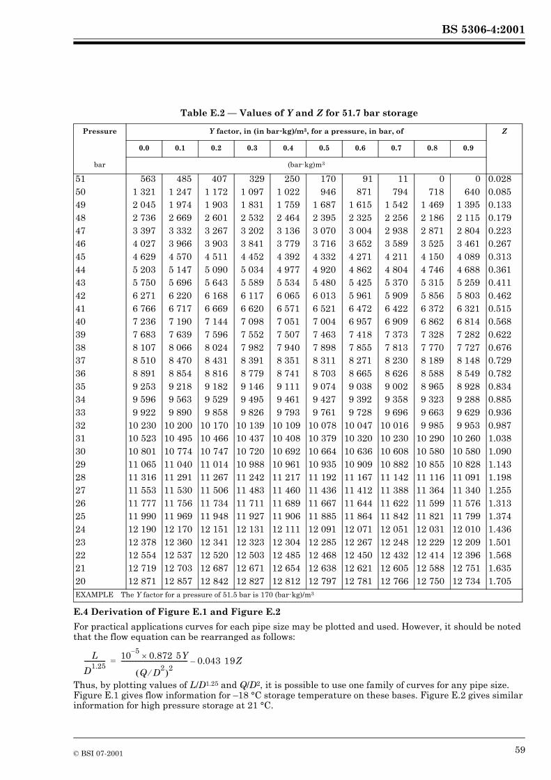
BS 5306-4:2001
Table E.2 — Values of Y and Z for 51.7 bar storage
E.4 Derivation of Figure E.1 and Figure E.2
For practical applications curves for each pipe size may be plotted and used. However, it should be noted that the flow equation can be rearranged as follows:
Thus, by plotting values of L/D1.25 and Q/D2, it is possible to use one family of curves for any pipe size. Figure E.1 gives flow information for –18 °C storage temperature on these bases. Figure E.2 gives similar information for high pressure storage at 21 °C.
Pressure Y factor, in (in bar����kg)/m3, for a pressure, in bar, of Z
0.0 0.1 0.2 0.3 0.4 0.5 0.6 0.7 0.8 0.9
bar (bar�kg)m3
51 563 485 407 329 250 170 91 11 0 0 0.02850 1 321 1 247 1 172 1 097 1 022 946 871 794 718 640 0.08549 2 045 1 974 1 903 1 831 1 759 1 687 1 615 1 542 1 469 1 395 0.13348 2 736 2 669 2 601 2 532 2 464 2 395 2 325 2 256 2 186 2 115 0.17947 3 397 3 332 3 267 3 202 3 136 3 070 3 004 2 938 2 871 2 804 0.22346 4 027 3 966 3 903 3 841 3 779 3 716 3 652 3 589 3 525 3 461 0.26745 4 629 4 570 4 511 4 452 4 392 4 332 4 271 4 211 4 150 4 089 0.31344 5 203 5 147 5 090 5 034 4 977 4 920 4 862 4 804 4 746 4 688 0.36143 5 750 5 696 5 643 5 589 5 534 5 480 5 425 5 370 5 315 5 259 0.41142 6 271 6 220 6 168 6 117 6 065 6 013 5 961 5 909 5 856 5 803 0.46241 6 766 6 717 6 669 6 620 6 571 6 521 6 472 6 422 6 372 6 321 0.51540 7 236 7 190 7 144 7 098 7 051 7 004 6 957 6 909 6 862 6 814 0.56839 7 683 7 639 7 596 7 552 7 507 7 463 7 418 7 373 7 328 7 282 0.62238 8 107 8 066 8 024 7 982 7 940 7 898 7 855 7 813 7 770 7 727 0.67637 8 510 8 470 8 431 8 391 8 351 8 311 8 271 8 230 8 189 8 148 0.72936 8 891 8 854 8 816 8 779 8 741 8 703 8 665 8 626 8 588 8 549 0.78235 9 253 9 218 9 182 9 146 9 111 9 074 9 038 9 002 8 965 8 928 0.83434 9 596 9 563 9 529 9 495 9 461 9 427 9 392 9 358 9 323 9 288 0.88533 9 922 9 890 9 858 9 826 9 793 9 761 9 728 9 696 9 663 9 629 0.93632 10 230 10 200 10 170 10 139 10 109 10 078 10 047 10 016 9 985 9 953 0.98731 10 523 10 495 10 466 10 437 10 408 10 379 10 320 10 230 10 290 10 260 1.03830 10 801 10 774 10 747 10 720 10 692 10 664 10 636 10 608 10 580 10 580 1.09029 11 065 11 040 11 014 10 988 10 961 10 935 10 909 10 882 10 855 10 828 1.14328 11 316 11 291 11 267 11 242 11 217 11 192 11 167 11 142 11 116 11 091 1.19827 11 553 11 530 11 506 11 483 11 460 11 436 11 412 11 388 11 364 11 340 1.25526 11 777 11 756 11 734 11 711 11 689 11 667 11 644 11 622 11 599 11 576 1.31325 11 990 11 969 11 948 11 927 11 906 11 885 11 864 11 842 11 821 11 799 1.37424 12 190 12 170 12 151 12 131 12 111 12 091 12 071 12 051 12 031 12 010 1.43623 12 378 12 360 12 341 12 323 12 304 12 285 12 267 12 248 12 229 12 209 1.50122 12 554 12 537 12 520 12 503 12 485 12 468 12 450 12 432 12 414 12 396 1.56821 12 719 12 703 12 687 12 671 12 654 12 638 12 621 12 605 12 588 12 751 1.63520 12 871 12 857 12 842 12 827 12 812 12 797 12 781 12 766 12 750 12 734 1.705EXAMPLE The Y factor for a pressure of 51.5 bar is 170 (bar�kg)/m3
L
D1.25-------------- 10 5– 0.872 5Y�
Q D2�� �
2------------------------------------------- 0.043 19Z –=
© BSI 07-2001 59
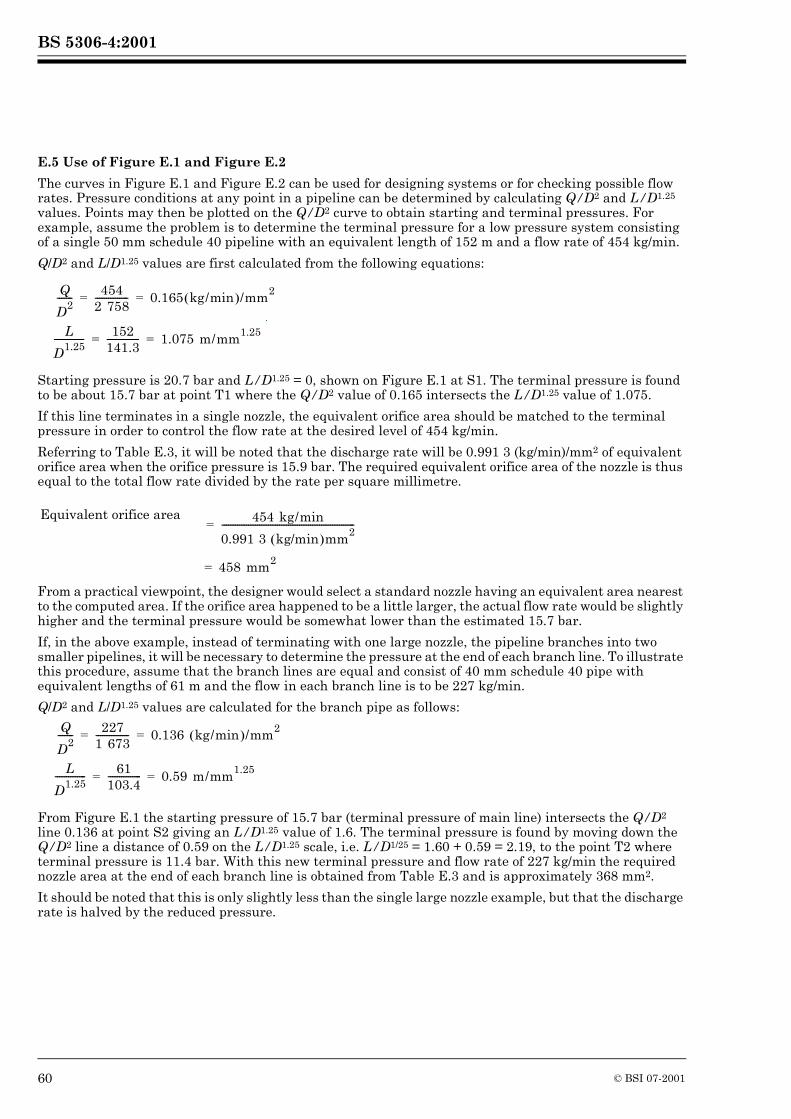
BS 5306-4:2001
E.5 Use of Figure E.1 and Figure E.2
The curves in Figure E.1 and Figure E.2 can be used for designing systems or for checking possible flow rates. Pressure conditions at any point in a pipeline can be determined by calculating Q/D2 and L/D1.25 values. Points may then be plotted on the Q/D2 curve to obtain starting and terminal pressures. For example, assume the problem is to determine the terminal pressure for a low pressure system consisting of a single 50 mm schedule 40 pipeline with an equivalent length of 152 m and a flow rate of 454 kg/min.
Q/D2 and L/D1.25 values are first calculated from the following equations:
Starting pressure is 20.7 bar and L/D1.25 = 0, shown on Figure E.1 at S1. The terminal pressure is found to be about 15.7 bar at point T1 where the Q/D2 value of 0.165 intersects the L/D1.25 value of 1.075.
If this line terminates in a single nozzle, the equivalent orifice area should be matched to the terminal pressure in order to control the flow rate at the desired level of 454 kg/min.
Referring to Table E.3, it will be noted that the discharge rate will be 0.991 3 (kg/min)/mm2 of equivalent orifice area when the orifice pressure is 15.9 bar. The required equivalent orifice area of the nozzle is thus equal to the total flow rate divided by the rate per square millimetre.
From a practical viewpoint, the designer would select a standard nozzle having an equivalent area nearest to the computed area. If the orifice area happened to be a little larger, the actual flow rate would be slightly higher and the terminal pressure would be somewhat lower than the estimated 15.7 bar.
If, in the above example, instead of terminating with one large nozzle, the pipeline branches into two smaller pipelines, it will be necessary to determine the pressure at the end of each branch line. To illustrate this procedure, assume that the branch lines are equal and consist of 40 mm schedule 40 pipe with equivalent lengths of 61 m and the flow in each branch line is to be 227 kg/min.
Q/D2 and L/D1.25 values are calculated for the branch pipe as follows:
From Figure E.1 the starting pressure of 15.7 bar (terminal pressure of main line) intersects the Q/D2 line 0.136 at point S2 giving an L/D1.25 value of 1.6. The terminal pressure is found by moving down the Q/D2 line a distance of 0.59 on the L/D1.25 scale, i.e. L/D1/25 = 1.60 + 0.59 = 2.19, to the point T2 where terminal pressure is 11.4 bar. With this new terminal pressure and flow rate of 227 kg/min the required nozzle area at the end of each branch line is obtained from Table E.3 and is approximately 368 mm2.
It should be noted that this is only slightly less than the single large nozzle example, but that the discharge rate is halved by the reduced pressure.
Equivalent orifice area
Q
D2------- 454
2 758--------------- 0.165 kg/min� �/mm2= =
L
D1.25-------------- 152
141.3--------------- 1.075 m/mm1.25= =
454 kg/min
0.991 3 kg/min� �mm2------------------------------------------------------------=
458 mm2=
Q
D2------- 227
1 673--------------- 0.136 kg/min� �/mm2= =
L
D1.25-------------- 61
103.4--------------- 0.59 m/mm1.25= =
60 © BSI 07-2001
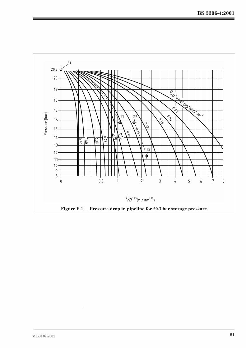
BS 5306-4:2001
Figure E.1 — Pressure drop in pipeline for 20.7 bar storage pressure
0 0.5 1 2 3 4 5 6 7 8
S1
20.7
20
19
18
17
16
15
14
13
12
11
10
9
8
T1 S2
T2
Pre
ssu
re (b
ar)
/D (m / mm )1 25 1 25L
0.5
0
0.4
0
0.3
0
0.2
5
0.2
0
0.1
8
0.16
0.14
0.12
0.10
0.09
0.08
Q/D = 0.07 (kg/min)/ mm
2
2
© BSI 07-2001 61
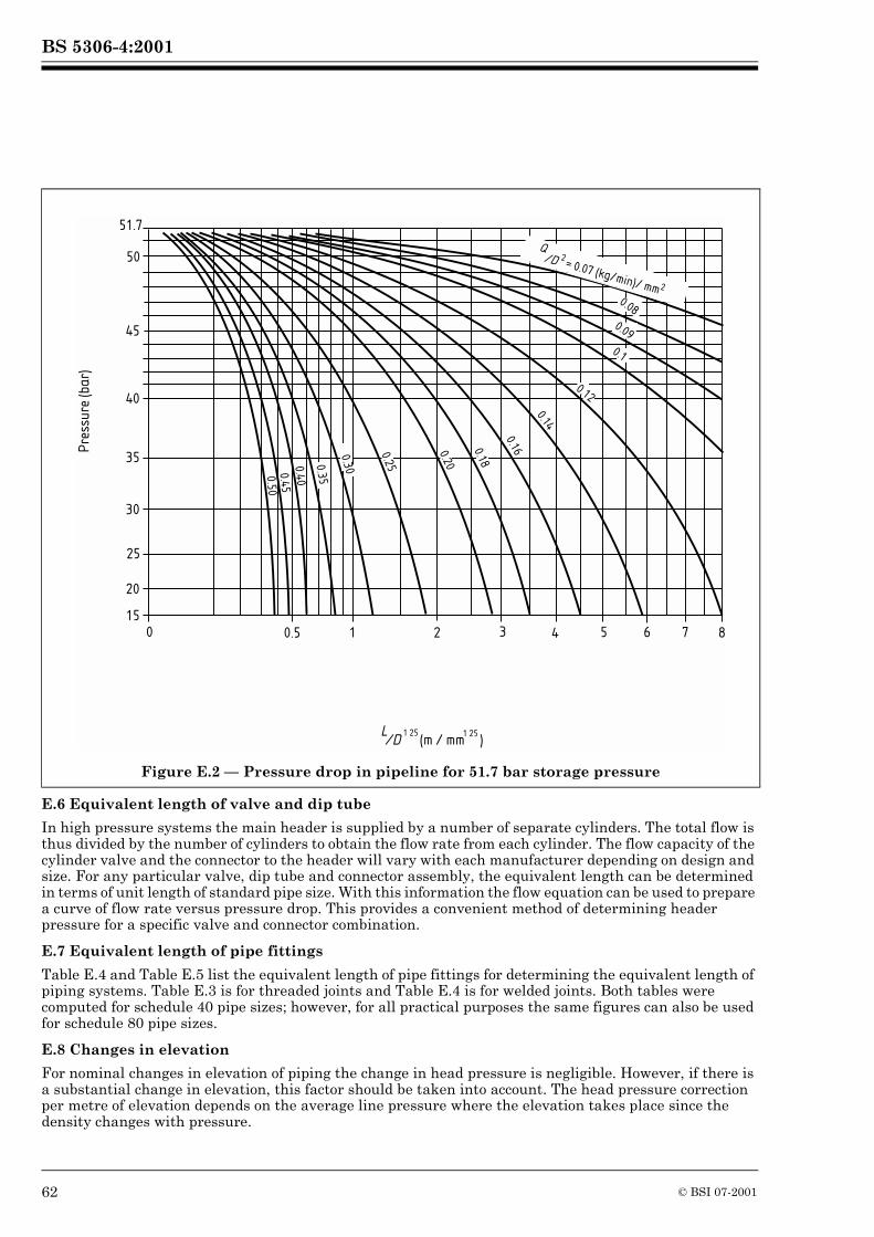
BS 5306-4:2001
E.6 Equivalent length of valve and dip tube
In high pressure systems the main header is supplied by a number of separate cylinders. The total flow is thus divided by the number of cylinders to obtain the flow rate from each cylinder. The flow capacity of the cylinder valve and the connector to the header will vary with each manufacturer depending on design and size. For any particular valve, dip tube and connector assembly, the equivalent length can be determined in terms of unit length of standard pipe size. With this information the flow equation can be used to prepare a curve of flow rate versus pressure drop. This provides a convenient method of determining header pressure for a specific valve and connector combination.
E.7 Equivalent length of pipe fittings
Table E.4 and Table E.5 list the equivalent length of pipe fittings for determining the equivalent length of piping systems. Table E.3 is for threaded joints and Table E.4 is for welded joints. Both tables were computed for schedule 40 pipe sizes; however, for all practical purposes the same figures can also be used for schedule 80 pipe sizes.
E.8 Changes in elevation
For nominal changes in elevation of piping the change in head pressure is negligible. However, if there is a substantial change in elevation, this factor should be taken into account. The head pressure correction per metre of elevation depends on the average line pressure where the elevation takes place since the density changes with pressure.
Figure E.2 — Pressure drop in pipeline for 51.7 bar storage pressure
0 0.5 1 2 3 4 5 6 7 8
51.7
45
20
25
30
35
15
40
Pre
ssu
re (b
ar)
/D (m / mm )1 25 1 25L
0.5
0
0.4
0
0.16
0.14
50
0.4
5
0.3
5
0.25
0.20
0.30
0.180.12
0.1
0.09
0.08
Q/D = 0.07 (kg/min)/ mm
2
2
62 © BSI 07-2001
BS 5306-4:2001
Correction factors are given in Table E.6 and Table E.7 for low pressure and high pressure systems respectively. The correction is subtracted from the terminal pressure when the flow is upward and added to the terminal pressure when the flow is upward and added to the terminal when the flow is downward. The terminal pressure at the outlet having been determined, appropriately sized nozzles can be selected.
For low pressure systems the discharge rate through equivalent orifices should be based on the values given in Table E.3. Design nozzle pressures should be not less than 10 bar.
For high pressure systems, the discharge rate through equivalent orifices should be based on the values given in Table E.8. Design nozzle pressures at 21 °C storage should be not less than 20 bar.
E.9 Calculation of equilibrium in low pressure systems
In high pressure systems the delay in achieving equilibrium flow will generally be insignificant. In low pressure systems the delay time and amount of carbon dioxide vaporized in cooling the pipe should be calculated and the equilibrium flow rate increased accordingly to deliver the desired quantity within the design time after the start of the discharge. Delay time and mass of carbon dioxide vaporized during this period may be calculated as follows.
Delay time, Dt, (in s) (low pressure systems):
Mass vaporized (low or high pressure systems):
where:
H is the latent heat of vaporization of liquid carbon dioxide in kilojoules per kilogram (kJ/kg)4)
W is the mass of carbon dioxide vaporized in kilograms (kg);W is the mass of piping in kilograms (kg);cp is the specific heat capacity of metal in pipe in kilojoules per kilogram kelvin [kJ/(kg�K)]
(0.46 for steel);T1 is the average pipe temperature before discharge in degrees Celsius (°C);
T2 is the average carbon dioxide temperature in degrees Celsius (°C);NOTE Assume 15.6 °C for high pressure and –20.6 °C for low pressure under normal conditions.
R is the design flow rate in kilograms per minute (kg/min);V is the volume of piping in cubic metres (m3);
4) Approximately 150.7 kJ/kg for high pressure and approximately 276.3 kJ/kg for low pressure systems.
Dt
wcp T1 T2–� �
0.507R----------------------------------- 16 850V
R-----------------------+=
Wwcp T1 T2–� �
H-----------------------------------=
© BSI 07-2001 63
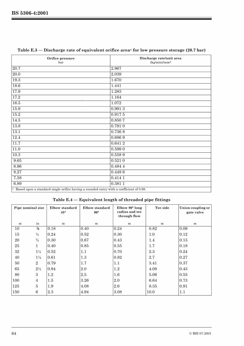
BS 5306-4:2001
Table E.3 — Discharge rate of equivalent orifice areaa for low pressure storage (20.7 bar)
Table E.4 — Equivalent length of threaded pipe fittings
Orifice pressurebar
Discharge rate/unit area(kg/min)/mm2
20.7 2.96720.0 2.03919.3 1.67018.6 1.44117.9 1.28317.2 1.16416.5 1.07215.9 0.991 315.2 0.917 514.5 0.850 713.8 0.791 013.1 0.736 812.4 0.686 911.7 0.641 211.0 0.599 010.3 0.558 9 9.65 0.521 0 8.96 0.484 4 8.27 0.448 6 7.58 0.414 1 6.89 0.381 1a Based upon a standard single orifice having a rounded entry with a coefficient of 0.98.
Pipe nominal size Elbow standard 45°
Elbow standard 90°
Elbow 90° long radius and tee through flow
Tee side Union coupling or gate valve
m in m m m m m
10 � 0.18 0.40 0.24 0.82 0.0915 ½ 0.24 0.52 0.30 1.0 0.1220 ¾ 0.30 0.67 0.43 1.4 0.1525 1 0.40 0.85 0.55 1.7 0.1832 1¼ 0.52 1.1 0.70 2.3 0.2440 1½ 0.61 1.3 0.82 2.7 0.2750 2 0.79 1.7 1.1 3.41 0.3765 2½ 0.94 2.0 1.2 4.08 0.4380 3 1.2 2.5 1.6 5.06 0.55
100 4 1.5 3.26 2.0 6.64 0.73125 5 1.9 4.08 2.6 8.35 0.91150 6 2.3 4.94 3.08 10.0 1.1
64 © BSI 07-2001
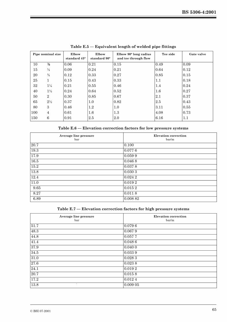
BS 5306-4:2001
Table E.5 — Equivalent length of welded pipe fittings
Table E.6 — Elevation correction factors for low pressure systems
Table E.7 — Elevation correction factors for high pressure systems
Pipe nominal size Elbow standard 45°
Elbow standard 90°
Elbow 90° long radius and tee through flow
Tee side Gate valve
10 � 0.06 0.21 0.15 0.49 0.0915 ½ 0.09 0.24 0.21 0.64 0.1220 ¾ 0.12 0.33 0.27 0.85 0.1525 1 0.15 0.43 0.33 1.1 0.1832 1¼ 0.21 0.55 0.46 1.4 0.2440 1½ 0.24 0.64 0.52 1.6 0.2750 2 0.30 0.85 0.67 2.1 0.3765 2½ 0.37 1.0 0.82 2.5 0.4380 3 0.46 1.2 1.0 3.11 0.55
100 4 0.61 1.6 1.3 4.08 0.73150 6 0.91 2.5 2.0 6.16 1.1
Average line pressurebar
Elevation correctionbar/m
20.7 0.10019.3 0.077 617.9 0.059 916.5 0.046 815.2 0.037 813.8 0.030 312.4 0.024 211.0 0.019 29.65 0.015 28.27 0.011 86.89 0.008 82
Average line pressurebar
Elevation correctionbar/m
51.7 0.079 648.3 0.067 944.8 0.057 741.4 0.048 637.9 0.040 034.5 0.033 931.0 0.028 327.6 0.023 824.1 0.019 220.7 0.015 817.2 0.012 413.8 0.009 05
© BSI 07-2001 65
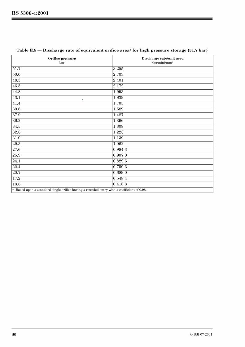
BS 5306-4:2001
Table E.8 — Discharge rate of equivalent orifice areaa for high pressure storage (51.7 bar)
Orifice pressurebar
Discharge rate/unit area(kg/min)/mm2
51.7 3.25550.0 2.70348.3 2.40146.5 2.17244.8 1.99343.1 1.83941.4 1.70539.6 1.58937.9 1.48736.2 1.39634.5 1.30832.8 1.22331.0 1.13929.3 1.06227.6 0.984 325.9 0.907 024.1 0.829 622.4 0.759 320.7 0.689 017.2 0.548 413.8 0.418 3a Based upon a standard single orifice having a rounded entry with a coefficient of 0.98.
66 © BSI 07-2001
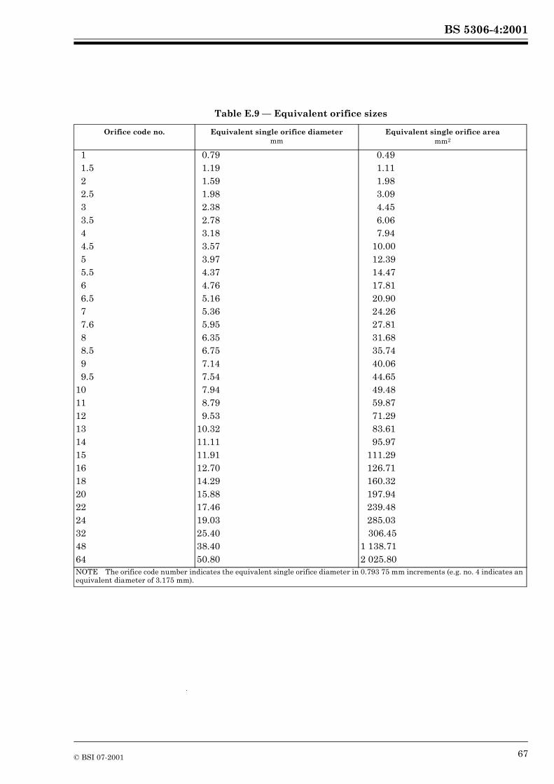
BS 5306-4:2001
Table E.9 — Equivalent orifice sizes
Orifice code no. Equivalent single orifice diametermm
Equivalent single orifice areamm2
1 0.79 0.491.5 1.19 1.112 1.59 1.982.5 1.98 3.093 2.38 4.453.5 2.78 6.064 3.18 7.944.5 3.57 10.005 3.97 12.395.5 4.37 14.476 4.76 17.816.5 5.16 20.907 5.36 24.267.6 5.95 27.818 6.35 31.688.5 6.75 35.749 7.14 40.069.5 7.54 44.65
10 7.94 49.4811 8.79 59.8712 9.53 71.2913 10.32 83.6114 11.11 95.9715 11.91 111.2916 12.70 126.7118 14.29 160.3220 15.88 197.9422 17.46 239.4824 19.03 285.0332 25.40 306.4548 38.40 1 138.7164 50.80 2 025.80NOTE The orifice code number indicates the equivalent single orifice diameter in 0.793 75 mm increments (e.g. no. 4 indicates an equivalent diameter of 3.175 mm).
© BSI 07-2001 67

68 blank
BS 5306-4:2001
Bibliography
Standards publications
BS 1600:1991, Dimensions of steel pipe for the petroleum industry.
BS 5306 (all parts), Fire extinguishing installations and equipment on premises.
BS 5430 (all parts), Periodic inspection testing and maintenance of transportable gas containers (excluding dissolved acetylene containers).
BS 7354:1990, Code of practice for design of high-voltage open-terminal stations.
BS EN 2, Classification of fires.
BS EN 3 (all parts), Portable fire extinguishers.
Other documents
[1] GREAT BRITAIN. Health and Safety at Work etc. Act 1974. London: The Stationery Office.
[2] GREAT BRITAIN. Factories Act 1961, Section 30, London: The Stationery Office.
[3] GREAT BRITAIN. Fire Precautions Act 1971, London: The Stationery Office.
© BSI 07-2001 69
BS 5306-4:2001
BSI
389 Chiswick High Road
London
W4 4AL
BSI — British Standards InstitutionBSI is the independent national body responsible for preparing British Standards. It presents the UK view on standards in Europe and at the international level. It is incorporated by Royal Charter.
Revisions
British Standards are updated by amendment or revision. Users of British Standards should make sure that they possess the latest amendments or editions.
It is the constant aim of BSI to improve the quality of our products and services. We would be grateful if anyone finding an inaccuracy or ambiguity while using this British Standard would inform the Secretary of the technical committee responsible, the identity of which can be found on the inside front cover. Tel: 020 8996 9000. Fax: 020 8996 7400.
BSI offers members an individual updating service called PLUS which ensures that subscribers automatically receive the latest editions of standards.
Buying standards
Orders for all BSI, international and foreign standards publications should be addressed to Customer Services. Tel: 020 8996 9001. Fax: 020 8996 7001. Standards are also available from the BSI website at http://www.bsi-global.com.
In response to orders for international standards, it is BSI policy to supply the BSI implementation of those that have been published as British Standards, unless otherwise requested.
Information on standards
BSI provides a wide range of information on national, European and international standards through its Library and its Technical Help to Exporters Service. Various BSI electronic information services are also available which give details on all its products and services. Contact the Information Centre. Tel: 020 8996 7111. Fax: 020 8996 7048.
Subscribing members of BSI are kept up to date with standards developments and receive substantial discounts on the purchase price of standards. For details of these and other benefits contact Membership Administration. Tel: 020 8996 7002. Fax: 020 8996 7001. Further information about BSI is available on the BSI website at http://www.bsi-global.com.
Copyright
Copyright subsists in all BSI publications. BSI also holds the copyright, in the UK, of the publications of the international standardization bodies. Except as permitted under the Copyright, Designs and Patents Act 1988 no extract may be reproduced, stored in a retrieval system or transmitted in any form or by any means – electronic, photocopying, recording or otherwise – without prior written permission from BSI.
This does not preclude the free use, in the course of implementing the standard, of necessary details such as symbols, and size, type or grade designations. If these details are to be used for any other purpose than implementation then the prior written permission of BSI must be obtained.
If permission is granted, the terms may include royalty payments or a licensing agreement. Details and advice can be obtained from the Copyright Manager. Tel: 020 8996 7070.