Embed Size (px)
Citation preview
1
Fire Detection Control PanelBC216-1User Manual - Part CParameter setup - Maintenance
2
Contents
1 Introduction 41.1 General 41.2 Symbols and type fonts 41.3 Important notes 4
2 Parameter setup by means of control panel keypad 62.1 Hints 62.2 Using the PC keyboard 72.2.1 Function keys 72.2.2 Editing functions 82.2.3 Other keys 82.3 Main menu point [Parameter settings] 82.3.1 Parameter setup of the global settings of the control panel - [Global settings] 92.3.2 Parameter setup of the function modules - [Function modules] 102.3.2.1 Parameter setup of a conventional detector interface GIF8-1 112.3.2.2 Parameter setup of a loop interface LIF64-1 122.3.3 Basic possibilities of parameter setup for the control panel outputs 172.3.3.1 Output types 182.3.3.2 Signal types 192.3.4 Parameter setup of the fire brigade interface - [FWI2-1] 202.3.4.1 Parameter setup of the fire brigade interface - relay outputs - [FWI relay outputs] 212.3.4.2 Parameter setup of the national version of the fire brigade control unit [FBCU country version] 222.3.4.3 Parameter setup of the fire brigade interface inputs [FWI inputs] 222.3.4.4 Parameter setup of the fire brigade interface open collector outputs [FWI oc-outputs] 242.3.5 Parameter setup of the auxiliary outputs and of the siren output - [NTB outputs] 262.3.6 Parameter setup of the LED-display field LAB48-1 - [LAB48-1] 272.3.7 Parameter setup of the detector zones - [Zone settings] 282.3.8 Parameter setup of actuations [Actuation settings] 292.3.9 Parameter setup of transmitting devices - [Transm. device set.] 312.3.10 Parameter setup of alarming devices [Alarming device set.] 332.3.11 Parameter setup of the interfaces - [Interfaces] 352.3.12 Automatic setup of the System configuration - [AUTO-setup] 362.4 Description of logic combinations 362.4.1 General 372.4.2 Logic combinations for transmitting devices and alarming devices 372.4.3 Logic combinations for actuations and actuation elements 382.4.4 Entering logic combinations 392.5 Standard parameter setup with AUTO-setup 412.6 Settings print-out 45
3 Parameter setup by means of PC and software PARSOFT-1 463.1 Installation of the parameter setup software PARSOFT-1 463.2 Functions of the parameter setup software PARSOFT-1 473.2.1 Menu bar 483.2.1.1 File management - menu point [File] 483.2.1.2 Data transfer - menu point “Communication” 493.2.1.3 Check settings and project information - menu point “Project” 50
3
3.2.1.4 Arrange windows - menu point “Window” 513.2.1.5 Information - menu point “Info” 513.2.2 Configuration window (system tree) 513.2.3 Parameter setup windows 513.2.4 Information window 523.3 Typical parameter setup process with PARSOFT-1 52
4 Maintenance, reconditioning 534.1 Maintenance 534.1.1 Checking the final charge voltage 534.1.2 Checking the stand-by batteries 534.1.3 Earth leakage monitoring 544.1.4 Function check 544.1.5 Maintenance support for loop elements 544.1.5.1 Maintenance support on the LC-display 554.1.5.2 Maintenance support on the printer 554.1.5.3 Replacement of an ADM- or ADMPRO-detector 564.1.6 Loading a new software version PL149 564.2 Reconditioning 584.2.1 Lost installer code 58
4
1 Introduction
1.1 GeneralThe present third part of the User Manual (Part C) of the fire detection control panel BC216-1 providesthe competent installer with the information necessary for parameter setup and maintenance of the controlpanel. This part of the manual is directly based on Part A and B of the User Manual. The determinations,remarks and explanations provided there will not be repeated in the present part of the manual. It is thereforeindispensable that you familiarise yourself with the contents of Part A and B of the User Manual beforestarting parameter setup and maintenance jobs.
1.2 Symbols and type fontsParticularly important text passages of this manual are marked with symbols as in Part A. The followingsymbols are used:
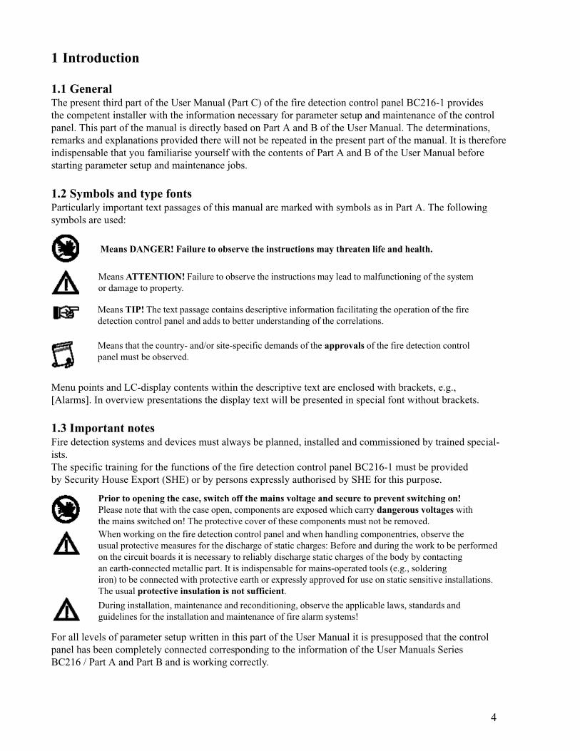
Means DANGER! Failure to observe the instructions may threaten life and health.
Means ATTENTION! Failure to observe the instructions may lead to malfunctioning of the systemor damage to property.
Means TIP! The text passage contains descriptive information facilitating the operation of the firedetection control panel and adds to better understanding of the correlations.
Means that the country- and/or site-specific demands of the approvals of the fire detection controlpanel must be observed.
Menu points and LC-display contents within the descriptive text are enclosed with brackets, e.g.,[Alarms]. In overview presentations the display text will be presented in special font without brackets.
1.3 Important notesFire detection systems and devices must always be planned, installed and commissioned by trained special-ists.The specific training for the functions of the fire detection control panel BC216-1 must be providedby Security House Export (SHE) or by persons expressly authorised by SHE for this purpose.
Prior to opening the case, switch off the mains voltage and secure to prevent switching on!Please note that with the case open, components are exposed which carry dangerous voltages withthe mains switched on! The protective cover of these components must not be removed.When working on the fire detection control panel and when handling componentries, observe theusual protective measures for the discharge of static charges: Before and during the work to be performedon the circuit boards it is necessary to reliably discharge static charges of the body by contactingan earth-connected metallic part. It is indispensable for mains-operated tools (e.g., solderingiron) to be connected with protective earth or expressly approved for use on static sensitive installations.The usual protective insulation is not sufficient.
During installation, maintenance and reconditioning, observe the applicable laws, standards andguidelines for the installation and maintenance of fire alarm systems!
For all levels of parameter setup written in this part of the User Manual it is presupposed that the controlpanel has been completely connected corresponding to the information of the User Manuals SeriesBC216 / Part A and Part B and is working correctly.

5
Always keep in mind that incorrectly entered parameters or incorrectly connected devices may lead to unin-tentional activation of system parts while doing commissioning and parameter setup jobs or during theconcluding test activities. Thereby, severe damage to property (e.g., by activating an extinguishing system)may result, emergency personnel may be alarmed or other undesired actuation procedures may beactivated. Therefore, reliably disable all parts (e.g., by disconnecting the actuation line), which can causedamage by inattendent activation during commissioning of the fire detection system. Make sure that thesedisabled parts are not re-enabled without your prior consent. Nevertheless, do not forget to re-enable thedisabled parts after ensuring the proper functioning of all system parts when finishing commissioning.

6
2 Parameter setup by means of control panel keypadThe parameter setup establishes the system-specific functions of the fire detection control panel. Themanifold possibilities offered by this control panel conversely require the definition of a very large numberof parameters. You establish all parameters by means of a clear menu control. The menu control itselfis described in detail in User Manual Series BC216 / Part A.
2.1 HintsThis chapter describes the parameter setup of the fire detection control panel at the technological level ofthe operating software with version number PL149 V4.11 (the version number of the software is displayedin the menu [System] - [Hardware components], see User Manual Series BC216 / Part A). Devicesusing software of older or later issuing level may differ, regarding their parameter options, from thescope of functions described here.Parameter setup of the control panel is only possible in authorisation level 3. To gain access, you have toenter your 5-digit installer code. In the state as delivered, the control panel installer code number “99999”is set as default. You must change the code as delivered before leaving the parameter setup menu.
You have 5 consecutive attempts of correctly entering the installer code at your disposal. After thefifth unsuccessful attempt, the control panel disables the entry of the installer code for 15 minutes forsafety reasons.With unauthorised or improper operation or parameter setup, the entire fire detection system maymalfunction or become entirely ineffective in extreme cases! Therefore, in your own interest, makesure that only few persons of your confidence are familiar with the installer code.
Please note that important system parts (e.g., a transmitting device) may be disabled automatically inauthorisation level 3. Inform the user on this effect.
You end the parameter setup process by confirming the main menu point [Exit authorization?] with the-button. The control panel checks the newly entered parameters for reasonableness and subsequently
replaces the previous parameters with the new values. The new parameters will become effective fromthat time on. An automatic restart is subsequently performed by the control panel during which all currentmessages will be reset as well.
Restart is only performed when parameters were changed during the preceding parameter setup.
All entered parameters are filed in a temporary memory for the time being. The contents of thismemory is transferred to the permanent memory of the control panel only upon proper completion ofthe parameter setup (menu point [Exit authorization?]), in which the data is kept as long as desiredeven with the system de-energised. Should you press the reset-button or de-energise the control panelbefore ending the parameter setup, the new parameter setup data will be lost and the original parametersremain effective!
Following the end of the parameter setup process it is indispensable to print out a parameter setup record(see Chapter 2.6: “Settings print-out”). This is the only way to keep clear and permanent records of themultitude of parameters of the fire detection control panel BC216-1 for future changes, maintenance andreconditioning tasks.
You can repeat the parameter setup process as often as you wish, the memory employed is practically notlimited with regard to the number of saving processes.
You can also change only parts of an existing parameter setup, it is not necessary that you go through allparameter operations. However, when changing a parameter setup, ensure that no senseless parametersituations (e.g., the parameters of an alarming device have been set but the activating event can no longeroccur since it has been removed by way of the parameters entered) are inadvertently created.

7
If you have set up a fire brigade interface relay output as a transmitting device which you subsequentlyput out of function by selecting [Not defined], all combinations and other settings of this transmittingdevice will be deleted.
Events occurring during authorisation level 3 are received, processed and indicated by the control panelas usual, taking into account the existing (not yet changed) parameter setup and the automatic disablementof system parts in authorisation level 3. Only for the time while new parameters are being installed(on completion of parameter setup) the control panel is not operational for approximately 5 seconds.
If you perform changes on a “live” fire detection system it is possible - while the control panel operatesat authorisation level 3 - that important system parts (e.g., the transmitting devices) are automaticallydisabled depending on the current parameter setup. During a fire alarm such system partswill not be activated!On switching back to authorisation level 1, all active alarm messages among other things will be resetduring the following restart of the control panel.Do not leave the control panel in authorisation level 3 for longer than absolutely necessary forparameter setup! After completion of the parameter setup, immediately switch back to authorisationlevel 1 in order to re-enable the disabled system parts.You can automatically configure the works settings in the menu point [Parameter settings] - [AUTOsetup]either for the entire control panel or only for newly added hardware components of the controlpanel (see Chapter 2.3.12: “Automatic setup of the System configuration - [AUTO-setup]”).
2.2 Using the PC keyboardThe control panel keypad is mainly designed for the user to operate the control panel. In general you canalso perform the parameter setup - except for text inputs - by using the keypad. However, parametersetup is performed much easier and more comfortably by means of a standard PC keyboard connected toconnector ST8 of the central processing board ZTB216-1 (see User Manual Series BC216 / Part B).
It is not necessary to de-energise the control panel for connecting and disconnecting the PC keyboard.However, safely discharge static charges by touching an earth-connected metallic part beforehand.
PC keyboards are produced by different manufacturers world-wide with a variety of specifications.Basically, the fire detection control panel BC216-1 should be able to process signals of all PC keyboardson the market; nevertheless, now and then it may occur that single keyboards are not entirelycompatible to the fire detection control panel BC216-1. Therefore, always pay attention to the charactersdisplayed on the LC-display when entering via a PC keyboard!
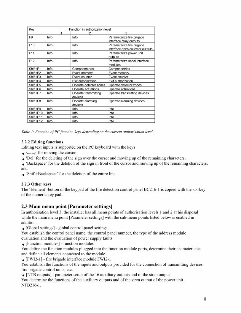
2.2.1 Function keysSpecial functions depending on the current authorisation level shown in the following table are assignedto the PC keyboard function keys F1, ..., F12.
Key Function in authorization level 1 2 3
F1 Info Info InfoF2 Silence buzzer/
Display testSilence buzzer/Display test
Silence buzzer/ Display test
F3 Info Info Parameterize function modulesF4 Info Info Parameterize fire brigade interfaceF5 Info Info Parameterize detector zonesF6 Info Info Parameterize actuationsF7 Info Info Parametrize transmitting deviceF8 Info Info Parameterize alarming devices
8
Table 1: Function of PC function keys depending on the current authorisation level
2.2.2 Editing functionsEditing text inputs is supported on the PC keyboard with the keys
for moving the cursor, ‘Del’ for the deleting of the sign over the cursor and moving up of the remaining characters, ‘Backspace’ for the deletion of the sign in front of the cursor and moving up of the remaining characters,
and ‘Shift+Backspace’ for the deletion of the entire line.
2.2.3 Other keysThe ‘Element’-button of the keypad of the fire detection control panel BC216-1 is copied with the -keyof the numeric key pad.
2.3 Main menu point [Parameter settings]In authorisation level 3, the installer has all menu points of authorisation levels 1 and 2 at his disposalwhile the main menu point [Parameter settings] with the sub-menu points listed below is enabled inaddition.
[Global settings] - global control panel settingsYou establish the control panel name, the control panel number, the type of the address moduleevaluation and the evaluation of power supply faults.
[Function modules] - function modulesYou define the function modules plugged into the function module ports, determine their characteristicsand define all elements connected to the module.
[FWI2-1] - fire brigade interface module FWI2-1You establish the functions of the inputs and outputs provided for the connection of transmitting devices,fire brigade control units, etc.
[NTB outputs] - parameter setup of the 16 auxiliary outputs and of the siren outputYou determine the functions of the auxiliary outputs and of the siren output of the power unitNTB216-1.
Key Function in authorization level 1 2 3
F9 Info Info Parameterize fire brigadeinterface relay outputs
F10 Info Info Parameterize fire brigadeinterface open collector outputs
F11 Info Info Parameterize power unitoutputs
F12 Info Info Parameterize serial interfacemodules
Shift+F1 Info Componentries ComponentriesShift+F2 Info Event memory Event memoryShift+F3 Info Event counter Event counterShift+F4 Info Exit authorization Exit authorizationShift+F5 Info Operate detector zones Operate detector zonesShift+F6 Info Operate actuations Operate actuationsShift+F7 Info Operate transmitting
devicesOperate transmitting devices
Shift+F8 Info Operate alarmingdevices
Operate alarming devices
Shift+F9 Info Info InfoShift+F10 Info Info InfoShift+F11 Info Info InfoShift+F12 Info Info Info
9
[LAB48-1] - parameter setup of the LED-display field LAB48-1You determine the event, which activates the light-emitting diode displays.
[Zone settings] - parameter setup of detector zonesYou determine the indication texts for the detector zones and elements. Before defining these values itis necessary that the detector zones have been determined in the menu point [Function modules].
[Actuation settings] - parameter setup of actuationsYou define the display text of the actuations and elements, the characteristics of the actuations, theevents activating these actuations and the logic combinations of the events. Before you can definethese values, it is necessary that the allocation of the actuations to physical outputs has been determinedin the menu points [Function modules], [FWI2-1] and [NTB outputs].
[Transm. device set.] - parameter setup of the transmitting devicesYou define the display text of the transmitting devices, the characteristics of the transmitting devices,the events activating these transmitting devices and the logic combinations of the events. Further, theparameters for the alarm delay (reaction time, delay time, alarm delay timer) are determined here. Beforeyou can define these values, it is necessary that the allocation of the transmitting devices to physicaloutputs has been determined in the menu points [FWI2-1] and [NTB outputs].
[Alarming device set.] - parameter setup of the alarming devicesYou define the display text of the alarming devices, the events activating these alarming devices andthe logic combinations of the events. Before you can define these values, it is necessary that the allocationof the alarming devices to physical outputs has been determined in the menu points [Functionmodules], [FWI2-1] and [NTB outputs].
[Interfaces] - parameter setup of serial interfacesYou determine the characteristics of the serial interfaces and the data printed on a connected printer.
[AUTO-setup]You reset all parameters to the basic setting of the installed modules. Once completed, you have toexit the menu point [Parameter settings] to make these parameters effective through the initiated restartof the control panel.
The sub-menu points are listed in detail in the following paragraphs.
Note for all sub-menu lists:The lists must be read from the top downwards: When accessing a sub-menu, the menu point writtenin the first place will always be shown. If a selection list follows instead of a sub-menu, the currentlyentered parameter will be shown.The default values of the selection lists are displayed during initial parameter setup. If individual valueshave already been entered, these will be displayed.For reasons of clarity, selection lists which are not self-explanatory (such as numerical inputs) arealso shown in form of a menu point.Observe the notes and footnotes included in the following lists!For reasons of clarity special hints on dangerous situations in these lists are no longer markedwith the symbols used in other chapters of this manual!
2.3.1 Parameter setup of the global settings of the control panel - [Global settings]In this menu point you
enter the control panel name and the control panel number, adjust the address module evaluation to the encoding of the installed address modules, and influence the evaluation of a mains fault, battery fault and earth leakage.
With a standard application you need not treat these parameters, you can jump this menu point. Theglobal parameters in this menu point need not be changed except in the case of special requirementson the control panel functions.
10
1) The address modules NG58-1 and NG60-1 used for addressing conventional detectors are - dependent on the originally employed control panel type - coded either binary (1, ..., 63) or BCD (1, ..., 39). When changing a control panel to a fire detection control panel BC216-1, you have to set the same coding that was used by the replaced control panel. The selected setting applies jointly to both possible conventional detector interfaces GIF8-1.2) A mains fault or battery fault is recognised and evaluated approximately 10 seconds after a control panel restart, a check is performed at 5 minute intervals during the running operation. These intervals are reduced to approximately 10 seconds in case of a fault, termination of a mains fault is therefore recognized within approximately 10 seconds.3) With suppressed mains fault evaluation, a mains fault or a fault of the power unit is not indicated on the control panel or passed on. If the emergency power supply through the stand-by batteries fails in addition, a total shut down of the entire fire detection system occurs without any further acoustic or optical warning.4) With suppressed battery failure evaluation, the failure of the stand-by battery (or its fuse) is not indicated on the control panel. If the mains or the control panel power unit fails in addition, the entire fire detection system is subject to total failure without any further acoustic or optical warning.5) An earth leakage at a point of the fire detection installation does not generally impair the functions. However, an additional earth leakage at another point of the installation may well lead to a failure of parts of the fire detection system, which is reported as a fault! If the earth leakage control is disabled, this must be taken into account through extended checks as part of the maintenance (see Chapter 4.1: “Maintenance”). The applicable European standards do not require earth leakage monitoring.
2.3.2 Parameter setup of the function modules - [Function modules]This menu point serves to determine the function modules plugged into the function module ports ST2and ST3 of the central processing board ZTB216-1 and their characteristics.When the menu point [AUTO-setup] has been called up, the control panel recognises what function moduleis employed on each port. If you wish to define the functions of a module port not yet fitted with a functionmodule, you will have to determine the type of the function module yourself in the menu point [Type].
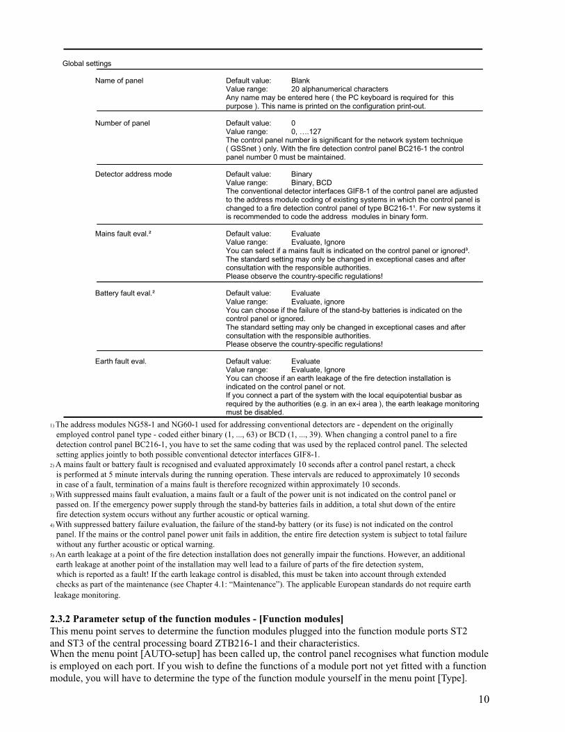
Global settings
Name of panel Default value: BlankValue range: 20 alphanumerical charactersAny name may be entered here ( the PC keyboard is required for thispurpose ). This name is printed on the configuration print-out.
Number of panel Default value: 0Value range: 0, ….127The control panel number is significant for the network system technique( GSSnet ) only. With the fire detection control panel BC216-1 the controlpanel number 0 must be maintained.
Detector address mode Default value: BinaryValue range: Binary, BCDThe conventional detector interfaces GIF8-1 of the control panel are adjustedto the address module coding of existing systems in which the control panel ischanged to a fire detection control panel of type BC216-1¹. For new systems itis recommended to code the address modules in binary form.
Mains fault eval.² Default value: EvaluateValue range: Evaluate, IgnoreYou can select if a mains fault is indicated on the control panel or ignored³.The standard setting may only be changed in exceptional cases and afterconsultation with the responsible authorities.Please observe the country-specific regulations!
Battery fault eval.² Default value: EvaluateValue range: Evaluate, ignoreYou can choose if the failure of the stand-by batteries is indicated on thecontrol panel or ignored.The standard setting may only be changed in exceptional cases and afterconsultation with the responsible authorities.Please observe the country-specific regulations!
Earth fault eval. Default value: EvaluateValue range: Evaluate, IgnoreYou can choose if an earth leakage of the fire detection installation isindicated on the control panel or not.If you connect a part of the system with the local equipotential busbar asrequired by the authorities (e.g. in an ex-i area ), the earth leakage monitoringmust be disabled.
11
The terms “physical address”, “logic address” and “loop position number” are used in this and furtherchapters. These initially confusing designations can be easily explained:
Physical addresses are determined by the equipment hardware or through adjusting elements: Thezone places 1, ..., 8 constitute physical addresses, which are unchangeably provided on the GIF8-1. Aloop element (e.g., a detector) possesses the physical address, which has been set on the detector bymeans of the adjusting switch.
Logic addresses are assigned to physical addresses by the configuration.You can for instance assign the logic address 11 to the GIF8-1 zone place with the physical addressNr. 3: An alarm of the zone place Nr. 3 will then be indicated on the LC-display as alarm of zone0011 (the logic address).You can assign the logic address “detector zone 75 / detector number 15” to the LIF64-1 - loop elementwith the physical address 80 (which was set or saved on the element): An alarm of the loop element80 will then be indicated on the LC-display as an alarm of detector 15 of detector zone 75 (0075/015).
Loop position numbers show the sequence in which the loop elements are arranged on the loop. Theloop position number is used in order to localise the fault during a line fault in the loop and for displayingon the LC-display.
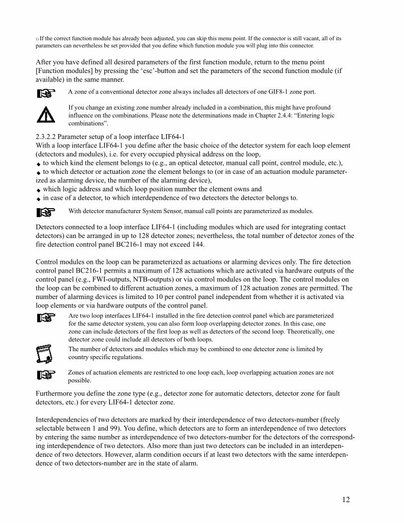
2.3.2.1 Parameter setup of a conventional detector interface GIF8-1You determine the zone type (e.g., manual call point, automatic detector, etc.) and the logic address ofeach zone for each of the 8 zone ports of the conventional detector interface GIF8-1.
Function modules Default value: 1Value range: 1, 2You select the function module FM-z to be processed.( FM-1= connector ST2, FM2= connector ST3 )
FM-z Default value: No module installedType ¹ Value range: No module installed, GIF8-1, LIF64-1
You have to define the type of function module. If you select [No moduleinstalled] a module installed in this port will not be further processed, all priorlymade settings (e.g., zones, elements, combinations, etc.) will be delete forthis module.
FM-z: GIF8-1 Default value: 1Detection lines: x Value range: 1, …8
You select the zone place of the selected conventional detector module to beprocessed.
FM-z GIF- line here you define the function to be performed by the selectedZone type conventional detector zone place Nr. x.
Not defined Zone place will not be used
Man. Call point Detector zone for manual call pointsZone
Automatic zone Detector zone for automatic fire detectors
Aut. Zone, verified Detector zone for automatic detectors with alarm verification
Technical message Detector zone for technical messages
Tech.mess. Detector zone for technical messages with self resetting (once theSelf-res. cause of the activation has been eliminated, the detector zone returns
automatically into normal condition).
Fault detection zone Detector zone for fault detectors
FM-z GIF-line x Default value: The lowest vacant number, starting with 1Zone number Value range: 1, ….9699
Here you determine the logic detector zone number, which is the zonenumber that will be shown on the display in the event of detection. I generalyou can specify any numbers within the permissible value range which needto be in order.
12
1) If the correct function module has already been adjusted, you can skip this menu point. If the connector is still vacant, all of itsparameters can nevertheless be set provided that you define which function module you will plug into this connector.
After you have defined all desired parameters of the first function module, return to the menu point[Function modules] by pressing the ‘esc’-button and set the parameters of the second function module (ifavailable) in the same manner.
A zone of a conventional detector zone always includes all detectors of one GIF8-1 zone port.
If you change an existing zone number already included in a combination, this might have profoundinfluence on the combinations. Please note the determinations made in Chapter 2.4.4: “Entering logiccombinations”.
2.3.2.2 Parameter setup of a loop interface LIF64-1With a loop interface LIF64-1 you define after the basic choice of the detector system for each loop element(detectors and modules), i.e. for every occupied physical address on the loop,
to which kind the element belongs to (e.g., an optical detector, manual call point, control module, etc.), to which detector or actuation zone the element belongs to (or in case of an actuation module parameter-
ized as alarming device, the number of the alarming device), which logic address and which loop position number the element owns and in case of a detector, to which interdependence of two detectors the detector belongs to.
With detector manufacturer System Sensor, manual call points are parameterized as modules.
Detectors connected to a loop interface LIF64-1 (including modules which are used for integrating contactdetectors) can be arranged in up to 128 detector zones; nevertheless, the total number of detector zones of thefire detection control panel BC216-1 may not exceed 144.
Control modules on the loop can be parameterized as actuations or alarming devices only. The fire detectioncontrol panel BC216-1 permits a maximum of 128 actuations which are activated via hardware outputs of thecontrol panel (e.g., FWI-outputs, NTB-outputs) or via control modules on the loop. The control modules onthe loop can be combined to different actuation zones, a maximum of 128 actuation zones are permitted. Thenumber of alarming devices is limited to 10 per control panel independent from whether it is activated vialoop elements or via hardware outputs of the control panel.
Are two loop interfaces LIF64-1 installed in the fire detection control panel which are parameterizedfor the same detector system, you can also form loop overlapping detector zones. In this case, onezone can include detectors of the first loop as well as detectors of the second loop. Theoretically, onedetector zone could include all detectors of both loops.
The number of detectors and modules which may be combined to one detector zone is limited bycountry specific regulations.
Zones of actuation elements are restricted to one loop each, loop overlapping actuation zones are notpossible.
Furthermore you define the zone type (e.g., detector zone for automatic detectors, detector zone for faultdetectors, etc.) for every LIF64-1 detector zone.
Interdependencies of two detectors are marked by their interdependence of two detectors-number (freelyselectable between 1 and 99). You define, which detectors are to form an interdependence of two detectorsby entering the same number as interdependence of two detectors-number for the detectors of the correspond-ing interdependence of two detectors. Also more than just two detectors can be included in an interdepen-dence of two detectors. However, alarm condition occurs if at least two detectors with the same interdepen-dence of two detectors-number are in the state of alarm.
13
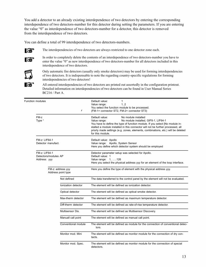
You add a detector to an already existing interdependence of two detectors by entering the correspondinginterdependence of two detectors-number for this detector during setting the parameters. If you are enteringthe value “0” as interdependence of two detectors-number for a detector, this detector is removedfrom the interdependence of two detectors.
You can define a total of 99 interdependence of two detectors-numbers.
The interdependencies of two detectors are always restricted to one detector zone each.
In order to completely delete the contents of an interdependence of two detectors-number you have toenter the value “0” as new interdependence of two detectors-number for all detectors included in thisinterdependence of two detectors.
Only automatic fire detectors (usually only smoke detectors) may be used for forming interdependenciesof two detectors. It is indispensable to note the regarding country-specific regulations for forminginterdependencies of two detectors!
All entered interdependencies of two detectors are printed out assortedly in the configuration printout.Detailed information on interdependencies of two detectors can be found in User Manual SeriesBC216 / Part A.
Function modules Default value: 1Value range: 1, 2You select the function module to be processed.(FM-1= connector ST2, FM-2= connector ST3)
FM-z Default value: No module installedType ¹ Value range: No module installed, GIF8-1, LIF64-1
You have to define the type of function module. If you select [No module in-stalled a module installed in this connector will not be further processed, allpriorly made settings (e.g. zones, elements, combinations, etc.) will be deletedfor this module.
FM-z: LIF64-1 Default value: ApolloDetector manufact. Value range: Apollo, System Sensor
Here you define which detector system should be employed
FM-z: LIF64-1 Detector parameter setup was selected for Apollo.Detectors/modules AP Default value: 1Address: yyy Value range: 1, …..126
Here you select the physical address yyy for an element of the loop interface.
FM-z: address yyy Here you define the type of element with the physical address yyy.Address point type
Not defined The data transferred to the control panel by the element will not be evaluated.
Ionization detector The element will be defined as ionization detector.
Optical detector The element will be defined as optical smoke detector.
Max-therm detector The element will be defined as maximum temperature detector.
Diff-therm detector The element will be defined as rate-of-rise temperature detector.
Multisensor Dis. The element will be defined as Multisensor Discovery.
Manuall call point The element will be defined as manual call point.
Conventional module The element will be defined as module for the connection of conventional detec-tors.
Monitor mod. Mini The element will be defined as monitor module for the connection of dry con-tacts.
Monitor mod. Spec. The element will be defined as monitor module for the connection of specialdetectors.
14
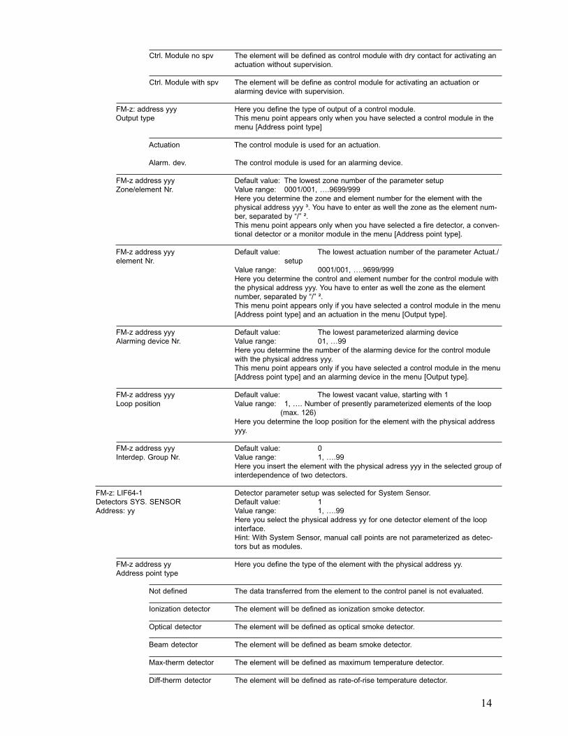
Ctrl. Module no spv The element will be defined as control module with dry contact for activating anactuation without supervision.
Ctrl. Module with spv The element will be define as control module for activating an actuation oralarming device with supervision.
FM-z: address yyy Here you define the type of output of a control module.Output type This menu point appears only when you have selected a control module in the
menu [Address point type]
Actuation The control module is used for an actuation.
Alarm. dev. The control module is used for an alarming device.
FM-z address yyy Default value: The lowest zone number of the parameter setupZone/element Nr. Value range: 0001/001, ….9699/999
Here you determine the zone and element number for the element with thephysical address yyy ³. You have to enter as well the zone as the element num-ber, separated by “/” ².This menu point appears only when you have selected a fire detector, a conven-tional detector or a monitor module in the menu [Address point type].
FM-z address yyy Default value: The lowest actuation number of the parameter Actuat./element Nr. setup
Value range: 0001/001, ….9699/999Here you determine the control and element number for the control module withthe physical address yyy. You have to enter as well the zone as the elementnumber, separated by “/” ².This menu point appears only if you have selected a control module in the menu[Address point type] and an actuation in the menu [Output type].
FM-z address yyy Default value: The lowest parameterized alarming deviceAlarming device Nr. Value range: 01, …99
Here you determine the number of the alarming device for the control modulewith the physical address yyy.This menu point appears only if you have selected a control module in the menu[Address point type] and an alarming device in the menu [Output type].
FM-z address yyy Default value: The lowest vacant value, starting with 1Loop position Value range: 1, …. Number of presently parameterized elements of the loop
(max. 126)Here you determine the loop position for the element with the physical addressyyy.
FM-z address yyy Default value: 0Interdep. Group Nr. Value range: 1, ….99
Here you insert the element with the physical adress yyy in the selected group ofinterdependence of two detectors.
FM-z: LIF64-1 Detector parameter setup was selected for System Sensor.Detectors SYS. SENSOR Default value: 1Address: yy Value range: 1, ….99
Here you select the physical address yy for one detector element of the loopinterface.Hint: With System Sensor, manual call points are not parameterized as detec-tors but as modules.
FM-z address yy Here you define the type of the element with the physical address yy.Address point type
Not defined The data transferred from the element to the control panel is not evaluated.
Ionization detector The element will be defined as ionization smoke detector.
Optical detector The element will be defined as optical smoke detector.
Beam detector The element will be defined as beam smoke detector.
Max-therm detector The element will be defined as maximum temperature detector.
Diff-therm detector The element will be defined as rate-of-rise temperature detector.
15
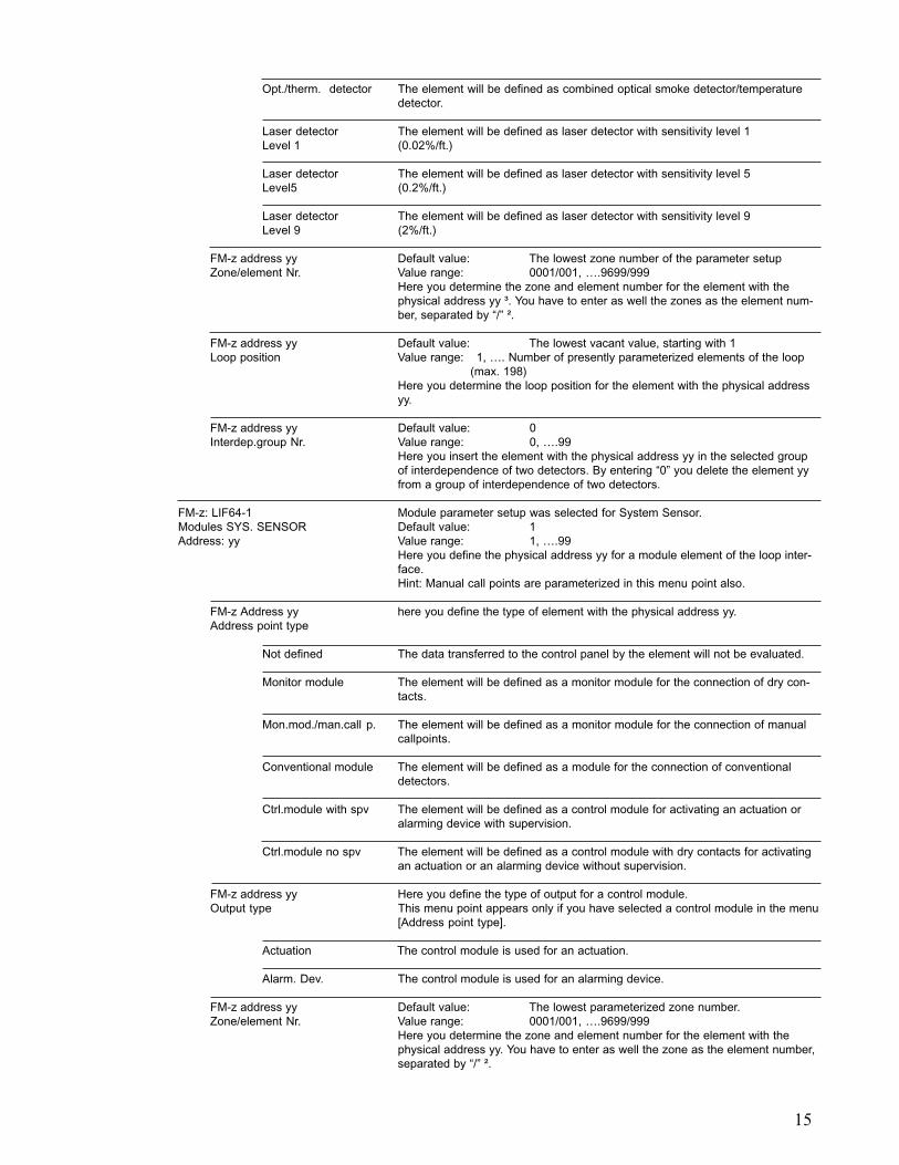
Opt./therm. detector The element will be defined as combined optical smoke detector/temperaturedetector.
Laser detector The element will be defined as laser detector with sensitivity level 1Level 1 (0.02%/ft.)
Laser detector The element will be defined as laser detector with sensitivity level 5Level5 (0.2%/ft.)
Laser detector The element will be defined as laser detector with sensitivity level 9Level 9 (2%/ft.)
FM-z address yy Default value: The lowest zone number of the parameter setupZone/element Nr. Value range: 0001/001, ….9699/999
Here you determine the zone and element number for the element with thephysical address yy ³. You have to enter as well the zones as the element num-ber, separated by “/” ².
FM-z address yy Default value: The lowest vacant value, starting with 1Loop position Value range: 1, …. Number of presently parameterized elements of the loop
(max. 198)Here you determine the loop position for the element with the physical addressyy.
FM-z address yy Default value: 0Interdep.group Nr. Value range: 0, ….99
Here you insert the element with the physical address yy in the selected groupof interdependence of two detectors. By entering “0” you delete the element yyfrom a group of interdependence of two detectors.
FM-z: LIF64-1 Module parameter setup was selected for System Sensor.Modules SYS. SENSOR Default value: 1Address: yy Value range: 1, ….99
Here you define the physical address yy for a module element of the loop inter-face.Hint: Manual call points are parameterized in this menu point also.
FM-z Address yy here you define the type of element with the physical address yy.Address point type
Not defined The data transferred to the control panel by the element will not be evaluated.
Monitor module The element will be defined as a monitor module for the connection of dry con-tacts.
Mon.mod./man.call p. The element will be defined as a monitor module for the connection of manualcallpoints.
Conventional module The element will be defined as a module for the connection of conventionaldetectors.
Ctrl.module with spv The element will be defined as a control module for activating an actuation oralarming device with supervision.
Ctrl.module no spv The element will be defined as a control module with dry contacts for activatingan actuation or an alarming device without supervision.
FM-z address yy Here you define the type of output for a control module.Output type This menu point appears only if you have selected a control module in the menu
[Address point type].
Actuation The control module is used for an actuation.
Alarm. Dev. The control module is used for an alarming device.
FM-z address yy Default value: The lowest parameterized zone number.Zone/element Nr. Value range: 0001/001, ….9699/999
Here you determine the zone and element number for the element with thephysical address yy. You have to enter as well the zone as the element number,separated by “/” ².
16
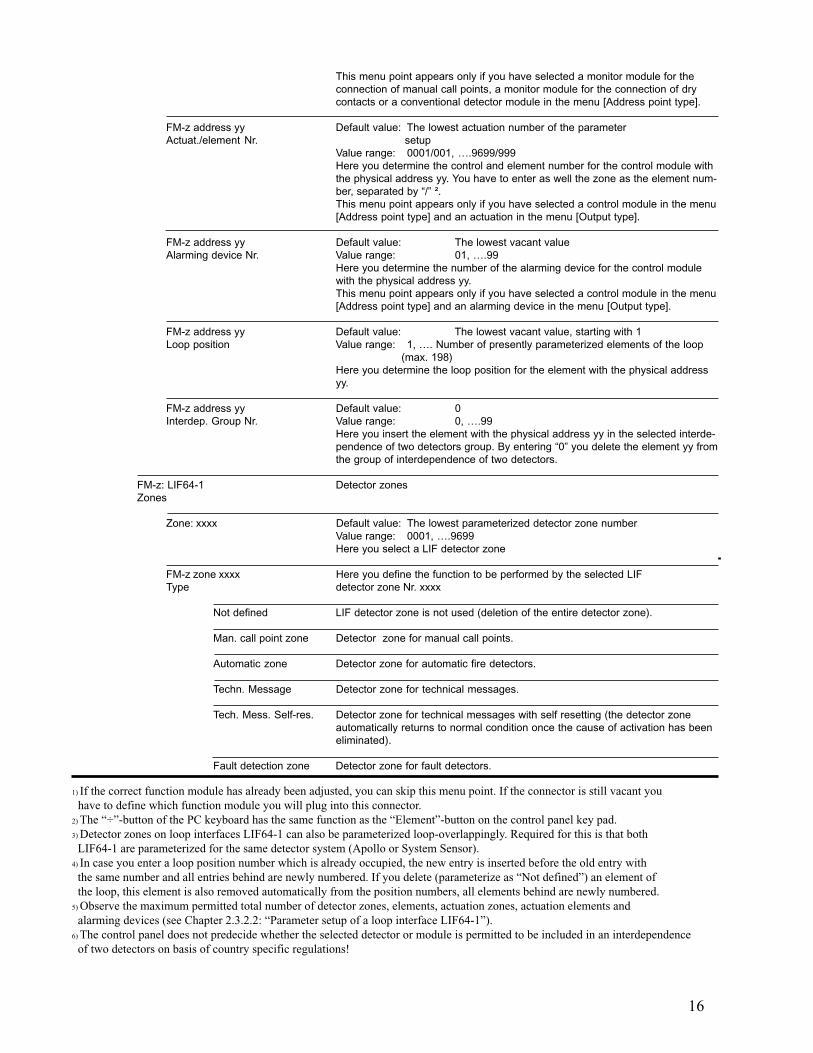
1) If the correct function module has already been adjusted, you can skip this menu point. If the connector is still vacant you have to define which function module you will plug into this connector.2) The “÷”-button of the PC keyboard has the same function as the “Element”-button on the control panel key pad.3) Detector zones on loop interfaces LIF64-1 can also be parameterized loop-overlappingly. Required for this is that both LIF64-1 are parameterized for the same detector system (Apollo or System Sensor).4) In case you enter a loop position number which is already occupied, the new entry is inserted before the old entry with the same number and all entries behind are newly numbered. If you delete (parameterize as “Not defined”) an element of the loop, this element is also removed automatically from the position numbers, all elements behind are newly numbered.5) Observe the maximum permitted total number of detector zones, elements, actuation zones, actuation elements and alarming devices (see Chapter 2.3.2.2: “Parameter setup of a loop interface LIF64-1”).6) The control panel does not predecide whether the selected detector or module is permitted to be included in an interdependence of two detectors on basis of country specific regulations!
This menu point appears only if you have selected a monitor module for theconnection of manual call points, a monitor module for the connection of drycontacts or a conventional detector module in the menu [Address point type].
FM-z address yy Default value: The lowest actuation number of the parameterActuat./element Nr. setup
Value range: 0001/001, ….9699/999Here you determine the control and element number for the control module withthe physical address yy. You have to enter as well the zone as the element num-ber, separated by “/” ².This menu point appears only if you have selected a control module in the menu[Address point type] and an actuation in the menu [Output type].
FM-z address yy Default value: The lowest vacant valueAlarming device Nr. Value range: 01, ….99
Here you determine the number of the alarming device for the control modulewith the physical address yy.This menu point appears only if you have selected a control module in the menu[Address point type] and an alarming device in the menu [Output type].
FM-z address yy Default value: The lowest vacant value, starting with 1Loop position Value range: 1, …. Number of presently parameterized elements of the loop
(max. 198)Here you determine the loop position for the element with the physical addressyy.
FM-z address yy Default value: 0Interdep. Group Nr. Value range: 0, ….99
Here you insert the element with the physical address yy in the selected interde-pendence of two detectors group. By entering “0” you delete the element yy fromthe group of interdependence of two detectors.
FM-z: LIF64-1 Detector zonesZones
Zone: xxxx Default value: The lowest parameterized detector zone numberValue range: 0001, ….9699Here you select a LIF detector zone
FM-z zone xxxx Here you define the function to be performed by the selected LIFType detector zone Nr. xxxx
Not defined LIF detector zone is not used (deletion of the entire detector zone).
Man. call point zone Detector zone for manual call points.
Automatic zone Detector zone for automatic fire detectors.
Techn. Message Detector zone for technical messages.
Tech. Mess. Self-res. Detector zone for technical messages with self resetting (the detector zoneautomatically returns to normal condition once the cause of activation has beeneliminated).
Fault detection zone Detector zone for fault detectors.

17
2.3.3 Basic possibilities of parameter setup for the control panel outputsThe control panel has the following individual outputs in the basic version:
1 siren output (usually used as the primary alarming device and 16 general auxiliary outputs,
all arranged on the power unit NTB216-1.
With the optional fire brigade interface FWI2-1 these outputs are expanded by 2 relays each with one dry change-over contact and 8 open collector (transistor) outputs.
These outputs are available for the connection of fire brigade devices and to accomplish actuations,transmitting devices, alarming installations and a series of special tasks (a summary of the options can befound in Chapter 2.3.3.1: “Output types”). An additional open collector output of the FWI2-1 has the function“System fault”, the parameters of which cannot be set.
With the optional fire brigade interface additional board FWZ2-1 used in addition to the FWI2-1 the outputsare expanded by
2 line surveilled outputs which are connected in parallel to the relay outputs of the FWI2-1.
Parameter setup is performed in three steps:
The first step of the parameter setup process of the outputs consists in assigning a task to each of theaforementioned physical outputs. This is done by determining the type of output, a summary of the possibleoutput types can be found in Chapter 2.3.3.1: “Output types”. Please note that each individual output can onlyassume one of these tasks.
Conversely, actuations, transmitting devices and alarming devices are only represented by one singleoutput. You can set the 7th auxiliary output as transmitting device Nr. 3. As a consequence, both the7th auxiliary output as well as the transmitting device Nr. 3 are occupied and no longer available forany other task.All other output types can also be applied to several outputs. It is possible, e.g., to set both the auxiliaryoutput Nr. 8 and Nr. 9 as output type [Earth fault].
With the output types actuation, transmitting device and alarming device you have to additionally specifya definition number of the respective installation. You can define a total of 128 actuations (or actuationzones), 10 transmitting devices and 10 alarming devices for the whole control panel. These numbers alreadycontain actuations and alarming devices which are realized by loop elements (i.e., by control modules).
The kind of effect of the activated output will be determined in the second step of the parameter setupprocess. A number of options are available (e.g., as continuous signal, delayed, pulsed signal, intermittingsignal, etc.). A summary of these can be found in Chapter 2.3.3.2: “Signal types”. The first two parametersetup steps are shown in Chapter 2.3.4: “Parameter setup of the fire brigade interface - [FWI2-1]” and inChapter 2.3.5: “Parameter setup of the auxiliary outputs and of the siren output - [NTB outputs]”.
In the third step of the parameter setup process, among other things, the message texts are determined,the operating characteristics are determined and the combinations are fixed for the defined actuations,transmitting devices and alarming devices.
If you change an existing zone number already included in a combination, this might have profoundinfluence on the combinations. Please note the determinations made in Chapter 2.4.4: “Entering logiccombinations”.
After you have defined all desired parameters of the first function module, return to the menu point[Function modules] by pressing the ‘esc’-button and set the parameters of the second function module (ifavailable) in the same manner.
18
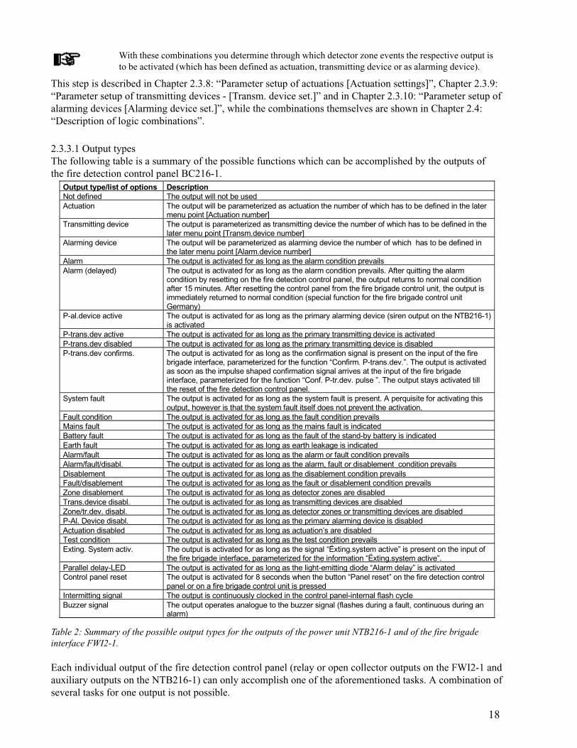
Table 2: Summary of the possible output types for the outputs of the power unit NTB216-1 and of the fire brigadeinterface FWI2-1.
Each individual output of the fire detection control panel (relay or open collector outputs on the FWI2-1 andauxiliary outputs on the NTB216-1) can only accomplish one of the aforementioned tasks. A combination ofseveral tasks for one output is not possible.
This step is described in Chapter 2.3.8: “Parameter setup of actuations [Actuation settings]”, Chapter 2.3.9:“Parameter setup of transmitting devices - [Transm. device set.]” and in Chapter 2.3.10: “Parameter setup ofalarming devices [Alarming device set.]”, while the combinations themselves are shown in Chapter 2.4:“Description of logic combinations”.
2.3.3.1 Output typesThe following table is a summary of the possible functions which can be accomplished by the outputs ofthe fire detection control panel BC216-1.
With these combinations you determine through which detector zone events the respective output isto be activated (which has been defined as actuation, transmitting device or as alarming device).
Output type/list of options DescriptionNot defined The output will not be usedActuation The output will be parameterized as actuation the number of which has to be defined in the later
menu point [Actuation number]Transmitting device The output is parameterized as transmitting device the number of which has to be defined in the
later menu point [Transm.device number]Alarming device The output will be parameterized as alarming device the number of which has to be defined in
the later menu point [Alarm.device number]Alarm The output is activated for as long as the alarm condition prevailsAlarm (delayed) The output is activated for as long as the alarm condition prevails. After quitting the alarm
condition by resetting on the fire detection control panel, the output returns to normal conditionafter 15 minutes. After resetting the control panel from the fire brigade control unit, the output isimmediately returned to normal condition (special function for the fire brigade control unitGermany)
P-al.device active The output is activated for as long as the primary alarming device (siren output on the NTB216-1)is activated
P-trans.dev active The output is activated for as long as the primary transmitting device is activatedP-trans.dev disabled The output is activated for as long as the primary transmitting device is disabledP-trans.dev confirms. The output is activated for as long as the confirmation signal is present on the input of the fire
brigade interface, parameterized for the function “Confirm. P-trans.dev.”. The output is activatedas soon as the impulse shaped confirmation signal arrives at the input of the fire brigadeinterface, parameterized for the function “Conf. P-tr.dev. pulse ”. The output stays activated tillthe reset of the fire detection control panel.
System fault The output is activated for as long as the system fault is present. A perquisite for activating thisoutput, however is that the system fault itself does not prevent the activation.
Fault condition The output is activated for as long as the fault condition prevailsMains fault The output is activated for as long as the mains fault is indicatedBattery fault The output is activated for as long as the fault of the stand-by battery is indicatedEarth fault The output is activated for as long as earth leakage is indicatedAlarm/fault The output is activated for as long as the alarm or fault condition prevailsAlarm/fault/disabl. The output is activated for as long as the alarm, fault or disablement condition prevailsDisablement The output is activated for as long as the disablement condition prevailsFault/disablement The output is activated for as long as the fault or disablement condition prevailsZone disablement The output is activated for as long as detector zones are disabledTrans.device disabl. The output is activated for as long as transmitting devices are disabledZone/tr.dev. disabl. The output is activated for as long as detector zones or transmitting devices are disabledP-Al. Device disabl. The output is activated for as long as the primary alarming device is disabledActuation disabled The output is activated for as long as actuation’s are disabledTest condition The output is activated for as long as the test condition prevailsExting. System activ. The output is activated for as long as the signal “Ëxting.system active” is present on the input of
the fire brigade interface, parameterized for the information “Ëxting.system active”.Parallel delay-LED The output is activated for as long as the light-emitting diode “Alarm delay” is activatedControl panel reset The output is activated for 8 seconds when the button “Panel reset” on the fire detection control
panel or on a fire brigade control unit is pressedIntermitting signal The output is continuously clocked in the control panel-internal flash cycleBuzzer signal The output operates analogue to the buzzer signal (flashes during a fault, continuous during an
alarm)

19
Outputs of control modules which are connected to a loop can be parameterized as actuation or asalarming device only (see Chapter 2.3.2.2: “Parameter setup of a loop interface LIF64-1").
2.3.3.2 Signal typesAll switching possibilities that can be set for a single output of the NTB216-1 or of the FWI2-1 aresummarised in the following table. Consider that restrictions exist for signal types, depending on the outputtype!
The following commitment applies: An output is “switched” when the output relay is activated or the output transistor is switched through
(i.e. the output is connected to ground (-)). An output is “switched off” when the output relay is released (i.e., out of power) or the output transistor
is open (i.e. the output is not connected to any defined potential).
Table 3: Summary of the possible signal types of the outputs arranged on the NTB216-1 and the FWI2-1.
The combination possibilities of output- and signal types are restricted as described in the following: The output is determined as a transmitting device:
Permissible signal types are: Continuous signal, continuous signal inverted, pulsed signal, pulsed signal retriggered.
The output is determined as an actuation or alarming device: Permissible signal types are: All signal types except for pulsed signal retriggered.
The output is determined asAlarm (delayed),Parallel delay-LED (activation as delay-LED)Control panel reset (activated for approx. 8 seconds during control panel reset),Intermitting signal (condition is changed with internal flash frequency),Buzzer signal (condition corresponds to buzzer activation):
The only permissible signal type for these output types is continuous signal, which is defined automaticallyby this output type and is therefore not setable.
All other outputs: Permissible signal types are: Continuous signal, continuous signal delayed, continuous signal inverted, continuous signal delayed/inverted.
Only the signal type possibilities are proposed during parameter setup which are permissible for therespective output type.
Signal type/selection list DescriptionContinuous signal The activated output is switched and remains switched for as long the criteria is connectedCont.sign., delayed The output is switched with delay and remains switched for as long as the criteria is connected.
The delay time is determined in the menu point [Activation delay]Cont.sign., invert. The output is switched in normal condition and is switched off by activation. It remains switch off for
as long as the criteria is connectedCont.sign., del/inv The output is switched in normal condition and is switched off by activation with delay. It remains
switched off for as long as the criteria is connected. The delay time will be determined in the menupoint [Activation delay]
Pulsed signal The output is switched briefly and subsequently switched off again. The impulse duration will bedetermined in the menu point [Pulse width]
Puls.sign., delayed The output is switched briefly after the delay and subsequently switched off again. The delay timeand the impulse duration will be determined in the menu points [Activation delay] and [Pulse width]
Puls.sign., retrig. The output is switched briefly and subsequently switched off again. During a subsequent activationit is switched again and it remains switched for as long as the activation criteria is available(function: Transmitting device Nuremberg). The impulse duration is determined in the menu point[Pulse width]

20
The inverted signal types [Cont. sign. invert.] and [Cont. sign. del/inv] are primarily intended forsummary fault messages or mains failure messages. In these cases it is more favourable to make theactivated device de-energised in case of an event (e.g., the stand-by battery is not additionally loadedwith the current of a connected relay coil during mains failure).
Only one of the aforementioned signal types can be selected for an output of the fire detection controlpanel (relay or open collector outputs on the FWI2-1 and the auxiliary outputs on the NTB216-1).
The outputs of control modules connected to a loop are dealt with in Chapter 2.3.8: “Parameter setupof actuations [Actuation settings]” and in Chapter 2.3.10: “Parameter setup of alarming devices[Alarming device set.]”.
2.3.4 Parameter setup of the fire brigade interface - [FWI2-1]The fire brigade interface FWI2-1 plugged into the connector ST4 of the central processing board is primarilyprovided for connecting the transmitting and display and operating devices required for the alarmtransmission to the fire brigade.
2 independent relay outputs with dry change-over contacts, 9 inputs and 8 open collector outputs
which are freely programmable, are available on the fire brigade interface for this purpose. All inputs andoutputs not required for fire brigade purposes can basically be used for any other task.
If your installation does not include a fire brigade interface module FWI2-1, you can skip all relatedparameter setup points.
If the optional fire brigade interface additional board FWZ2-1 is plugged onto the fire brigade interfaceFWI2-1, two line-monitored actuations (primarily for transmitting devices) are available in addition.These will be activated by the same signals, which also drive the two relay outputs. The supervising currentof the line monitoring can be selected in three stages - depending on the local transmission system - the valuescan be retrieved from the specifications in User Manual Series BC216 / Part B.
Special groupings of outputs and inputs were formed at the factory for different standard fire brigade controlunits and other fire brigade installations that can be selected in a separate sub-menu. Fire brigade control unitsnot corresponding to this pre-programmed standard must be individually parameterized by you.
The parameters of the fire brigade interface FWI2-1 (with the plugged-on fire brigade interface additionalboard FWZ2-1) are set in the following sub-menu points of the menu [FWI2-1].
1) This menu point is only displayed if the input of a value is efficient on the basis of the preceding menu entries.
FWI2-1
FWI configuration You decide whether a fire brigade interface is installed and which.
No FWI installed No fire brigade interface installed.
FWI2-1 The FWI2-1 is installed.
FWI2-1 and FWZ2-1 The FWI2-1 with plugged-on FWZ2-1 is installed.
FWI relay outputs ¹ You determine the functions to be fulfilled by the two relay outputs of theFWI2-1 and two monitored outputs of the FWZ2-1.
FBCU country version ¹ You set the configuration predefined at the factory to suit the respectivenational fire brigade control unit and other fire brigade installations.
FWI inputs ¹ You determine the functions to be performed by the 9 inputs of the FWI2-1.
FWI oc-outputs ¹ You determine the functions to be performed by the 8-parameterizable opencollector outputs of the FWI2-1.
21
For standard applications you need only determine the national fire brigade control unit, all other parametersof the fire detection control panel which were factory set can be left as they were. However, compare thestandard parameters written in Chapter 2.5: “Standard parameter setup with AUTOsetup” with the require-ments of your system.
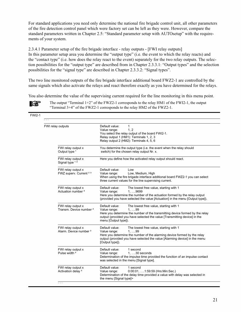
2.3.4.1 Parameter setup of the fire brigade interface - relay outputs - [FWI relay outputs]In this parameter setup area you determine the “output type” (i.e. the event to which the relay reacts) andthe “contact type” (i.e. how does the relay react to the event) separately for the two relay outputs. The selec-tion possibilities for the “output type” are described from in Chapter 2.3.3.1: “Output types” and the selectionpossibilities for the “signal type” are described in Chapter 2.3.3.2: “Signal types”.
The two line monitored outputs of the fire brigade interface additional board FWZ2-1 are controlled by thesame signals which also activate the relays and react therefore exactly as you have determined for the relays.
You also determine the value of the supervising current required for the line monitoring in this menu point.
The output “Terminal 1+2” of the FWZ2-1 corresponds to the relay HM1 of the FWI2-1, the output“Terminal 3+4” of the FWZ2-1 corresponds to the relay HM2 of the FWZ2-1.
FWI2-1. . .
FWI relay outputs Default value: 1Value range: 1, 2You select the relay output of the board FWI2-1.Relay output 1 (HM1): Terminals 1, 2, 3Relay output 2 (HM2): Terminals 4, 5, 6
FWI relay output x You determine the output type (i.e. the event when the relay shouldOutput type ¹ switch) for the chosen relay output Nr. x.
FWI relay output x Here you define how the activated relay output should react.Signal type ¹ ²
FWI relay output x Default value: LowFWZ superv. Current ² ³ Value range: Low, Medium, High
When using the fire brigade interface additional board FWZ2-1 you can selectthree current values for the line supervising current.
FWI relay output x Default value: The lowest free value, starting with 1Actuation number ² Value range: 1, ….9699
Here you determine the number of the actuation formed by the relay output(provided you have selected the value [Actuation] in the menu [Output type]).
FWI relay output x Default value: The lowest free value, starting with 1Transm. Device number ² Value range: 1, ….99
Here you determine the number of the transmitting device formed by the relayoutput (provided you have selected the value [Transmitting device] in themenu [Output type]).
FWI relay output x Default value: The lowest free value, starting with 1Alarm. Device number ² Value range: 1, ….99
Here you determine the number of the alarming device formed by the relayoutput (provided you have selected the value [Alarming device] in the menu[Output type]).
FWI relay output x Default value: 1 secondPulse width ² Value range: 1, ….30 seconds
Determination of the impulse time provided the function of an impulse contactwas selected in the menu [Signal type].
FWI relay output x Default value: 1 secondActivation delay ² Value range: 0:00:01, ….1:59:59 (Hrs:Min:Sec.)
Determination of the delay time provided a value with delay was selected inthe menu [Signal type]>
. . .

22
2) This menu point is only displayed if the input of a value is efficient on the basis of the preceding menu entries.3) This menu point is supported for transmitting devices only.4) You can define up to 128 actuations (or actuation zones), 10 transmitting devices and 10 alarming devices for the entire control panel, including the actuations and alarming devices formed by means of loop elements.
After you have defined the first relay output, return to the menu point [FWI relay outputs] by pressing the‘esc’-button and set the parameters of the second relay output in the same manner.
The inverted signal types [Cont. sign. invert.] and [Cont. sign. del/inv] are primarily intended for summaryfault messages or mains failure messages. In these cases it is advantageous if the relay is released in theevent of a fault (e.g., the stand-by battery is not additionally loaded with the current drawn by the relaycoil during a fault signal caused by mains failure).
2.3.4.2 Parameter setup of the national version of the fire brigade control unit [FBCU country version]In this parameter setup area you determine the national version of the fire brigade control unit to beconnected.In this way the required inputs and outputs of the fire brigade interface FWI2-1 are preset toworks settings.
The resulting assignment of the inputs and outputs of the fire brigade interface FWI2-1 can be foundin User Manual Series BC216 / Part B, chapter “Connection of country-specific fire brigade installations”.
All parameters of the inputs and outputs of the FWI2-1 not required for the chosen fire brigade controlunit can be freely set to suit individual purposes.
This menu point is not supported in the current software version PL149 V4.11.
2.3.4.3 Parameter setup of the fire brigade interface inputs [FWI inputs]In this parameter setup area you determine the desired functions for each of the 9 inputs of the fire brigadeinterface FWI2-1. If you have already set the parameters for the inputs and outputs of a fire brigade controlunit national version, you may only treat the inputs not used by the fire brigade control unit here, otherwisethe fire brigade control unit will not work correctly.
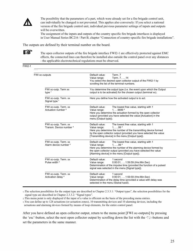
The possibility that the parameters of a part, which were already set for a fire brigade control unit, canindividually be changed is not prevented. This applies also conversely: If you select a national versionof the fire brigade control unit, individual previous parameter settings of inputs and outputs will beoverwritten.The assignment of the inputs and outputs of the country specific fire brigade interfaces is displayed in UserManual Series BC216 / Part B, chapter “Connection of country-specific fire brigade installations”.
Since these inputs have mainly been designed for the control of the control panel from a fire brigade controlunit, the function of the inputs is not dependent on the current authorisation level of the control panel.
In general, the inputs of the fire brigade interface module have equivalent rank with command inputs via thecontrol panel keypad. The most recent command will be executed in each case unless the detail descriptiondetermines otherwise.
1) The selection possibilities for the output type are described in Chapter 2.3.3.1: “Output types” and the selection possibilities for signal type are described in Chapter 2.3.3.2: “Signal types”.
FWI2-1…
FBCU country version
User definable The input and output parameters can be set freely
Austria Fire brigade control unit according to ÖNORM F3031 type A
Germany Fire brigade control unit according to DIN 14661
Switzerland Fire brigade control unit according to SN 054002
Netherlands Standard connections see NL documentation
Others ¹. . .
23
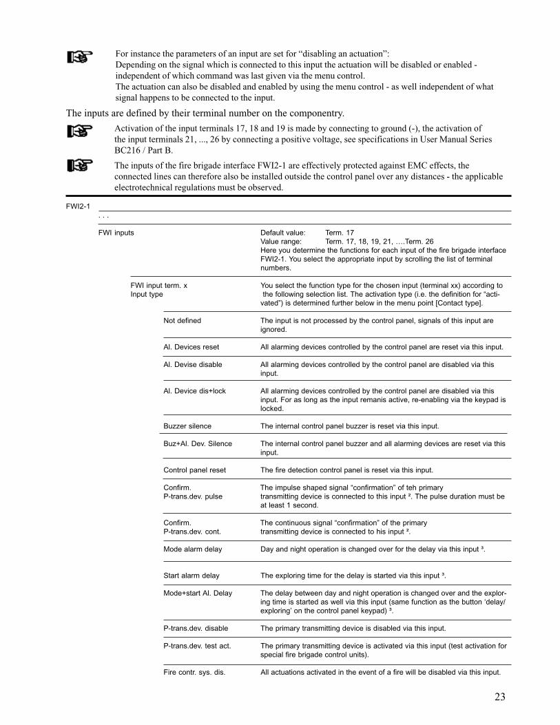
For instance the parameters of an input are set for “disabling an actuation”:Depending on the signal which is connected to this input the actuation will be disabled or enabled -independent of which command was last given via the menu control.The actuation can also be disabled and enabled by using the menu control - as well independent of whatsignal happens to be connected to the input.
The inputs are defined by their terminal number on the componentry.
Activation of the input terminals 17, 18 and 19 is made by connecting to ground (-), the activation ofthe input terminals 21, ..., 26 by connecting a positive voltage, see specifications in User Manual SeriesBC216 / Part B.
The inputs of the fire brigade interface FWI2-1 are effectively protected against EMC effects, theconnected lines can therefore also be installed outside the control panel over any distances - the applicableelectrotechnical regulations must be observed.
FWI2-1. . .
FWI inputs Default value: Term. 17Value range: Term. 17, 18, 19, 21, ….Term. 26Here you determine the functions for each input of the fire brigade interfaceFWI2-1. You select the appropriate input by scrolling the list of terminalnumbers.
FWI input term. x You select the function type for the chosen input (terminal xx) according toInput type the following selection list. The activation type (i.e. the definition for “acti-
vated”) is determined further below in the menu point [Contact type].
Not defined The input is not processed by the control panel, signals of this input areignored.
Al. Devices reset All alarming devices controlled by the control panel are reset via this input.
Al. Devise disable All alarming devices controlled by the control panel are disabled via thisinput.
Al. Device dis+lock All alarming devices controlled by the control panel are disabled via thisinput. For as long as the input remanis active, re-enabling via the keypad islocked.
Buzzer silence The internal control panel buzzer is reset via this input.
Buz+Al. Dev. Silence The internal control panel buzzer and all alarming devices are reset via thisinput.
Control panel reset The fire detection control panel is reset via this input.
Confirm. The impulse shaped signal “confirmation” of teh primaryP-trans.dev. pulse transmitting device is connected to this input ². The pulse duration must be
at least 1 second.
Confirm. The continuous signal “confirmation” of the primaryP-trans.dev. cont. transmitting device is connected to his input ².
Mode alarm delay Day and night operation is changed over for the delay via this input ³.
Start alarm delay The exploring time for the delay is started via this input ³.
Mode+start Al. Delay The delay between day and night operation is changed over and the explor-ing time is started as well via this input (same function as the button ‘delay/exploring’ on the control panel keypad) ³.
P-trans.dev. disable The primary transmitting device is disabled via this input.
P-trans.dev. test act. The primary transmitting device is activated via this input (test activation forspecial fire brigade control units).
Fire contr. sys. dis. All actuations activated in the event of a fire will be disabled via this input.
24
1) This menu point is only displayed if the input of a value is efficient on the basis of the preceding menu entries.2) Please retrieve information on what signal type is supplied for confirmation by the transmitting device used from the manuals of the transmitting device.3) These inputs act only on the primary transmitting device.
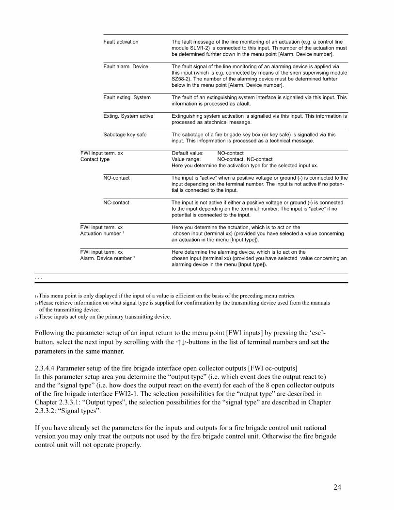
Following the parameter setup of an input return to the menu point [FWI inputs] by pressing the ‘esc’-button, select the next input by scrolling with the -buttons in the list of terminal numbers and set theparameters in the same manner.
2.3.4.4 Parameter setup of the fire brigade interface open collector outputs [FWI oc-outputs]In this parameter setup area you determine the “output type” (i.e. which event does the output react to)and the “signal type” (i.e. how does the output react on the event) for each of the 8 open collector outputsof the fire brigade interface FWI2-1. The selection possibilities for the “output type” are described inChapter 2.3.3.1: “Output types”, the selection possibilities for the “signal type” are described in Chapter2.3.3.2: “Signal types”.
If you have already set the parameters for the inputs and outputs for a fire brigade control unit nationalversion you may only treat the outputs not used by the fire brigade control unit. Otherwise the fire brigadecontrol unit will not operate properly.
Fault activation The fault message of the line monitoring of an actuation (e.g. a control linemodule SLM1-2) is connected to this input. Th number of the actuation mustbe determined furhter down in the menu point [Alarm. Device number].
Fault alarm. Device The fault signal of the line monitoring of an alarming device is applied viathis input (which is e.g. connected by means of the siren supervising moduleSZ58-2). The number of the alarming device must be determined furhterbelow in the menu point [Alarm. Device number].
Fault exting. System The fault of an extinguishing system interface is signalled via this input. Thisinformation is processed as afault.
Exting. System active Extinguishing system activation is signalled via this input. This information isprocessed as atechnical message.
Sabotage key safe The sabotage of a fire brigade key box (or key safe) is signalled via thisinput. This infoprmation is processed as a technical message.
FWI input term. xx Default value: NO-contactContact type Value range: NO-contact, NC-contact
Here you determine the activation type for the selected input xx.
NO-contact The input is “active” when a positive voltage or ground (-) is connected to theinput depending on the terminal number. The input is not active if no poten-tial is connected to the input.
NC-contact The input is not active if either a positive voltage or ground (-) is connectedto the input depending on the terminal number. The input is “active” if nopotential is connected to the input.
FWI input term. xx Here you determine the actuation, which is to act on theActuation number ¹ chosen input (terminal xx) (provided you have selected a value concerning
an actuation in the menu [Input type]).
FWI input term. xx Here determine the alarming device, which is to act on theAlarm. Device number ¹ chosen input (terminal xx) (provided you have selected value concerning an
alarming device in the menu [Input type]).
. . .
25
The possibility that the parameters of a part, which were already set for a fire brigade control unit,can individually be changed is not prevented. This applies also conversely: If you select a nationalversion of the fire brigade control unit, individual previous parameter settings of inputs and outputswill be overwritten.The assignment of the inputs and outputs of the country specific fire brigade interfaces is displayedin User Manual Series BC216 / Part B, chapter “Connection of country-specific fire brigade installations”.
The outputs are defined by their terminal number on the board.
The open collector outputs of the fire brigade interface FWI2-1 are effectively protected against EMCeffects, the connected lines can therefore be installed also outside the control panel over any distances- the applicable electrotechnical regulations must be observed.
1) The selection possibilities for the output type are described in Chapter 2.3.3.1: “Output types”, the selection possibilities for the signal type are described in Chapter 2.3.3.2: “Signal types”.2) This menu point is only displayed if the input of a value is efficient on the basis of the preceding menu entries.3) You can define up to 128 actuations (or actuation zones), 10 transmitting devices and 10 alarming devices, including the actuations and alarming devices formed by means of loop elements, for the entire control panel.
After you have defined an open collector output, return to the menu point [FWI oc-outputs] by pressingthe ‘esc’-button, select the next open collector output by scrolling down the list with the -buttons andset the parameters in the same manner.
FWI2-1. . .
FWI oc-outputs Default value: Term. 7Value range: Term. 7, ….14You select the desired open collector output of the FWI2-1 byscrolling the list of the terminal numbers.
FWI oc-outp. Term xx You determine the output type (i.e. the event upon which the Outputtype ¹ output is to be activated) for the chosen output (terminal xx).
FWI oc-outp. Term. xx Here you define how the activated output is to act.Signal type ¹
FWI oc-outp. Term. xx Default value: The lowest free value, starting with 1Actuation number ² Value range: 1, …9699 ³
Here you determine the actuation formed by the open collectoroutput (provided you have selected the value [Actuation] in themenu [Output type]).
FWI oc-outp. Term. xx Default value: The lowest free value, starting with 1Transm. Device number ² Value range: 1, ….99 ³
Here you determine the number of the transmitting device formedby the open collector output (provided you have selected the value[Transmitting device] in the menu [Output type]).
FWI oc-outp. Term. xx Default value: The lowest free value, starting with 1Alarm device number ² Value range: 1, ….99 ³
Here you determine the number of the alarming device formed bythe open collector output (provided you have selected the value[Alarming device] in the menu [Output type]).
FWI oc-outp. Term. xx Default value: 1 secondPulse width ² Value range: 0:00:01, ….1:59:59 (Hrs:Min:Sec)
Determination of the impulse time (provided the function of a pulsedsignal was selected in the menu [Signal type]).
FWI oc-outp. Term. xx Default value: 1 secondActivation delay ² Value range: 0:00:01, ….1:59:59 (Hrs:Min:Sec)
Determination of the delay time (provided a value with delay wasselected in the menu [Signal type]).
26
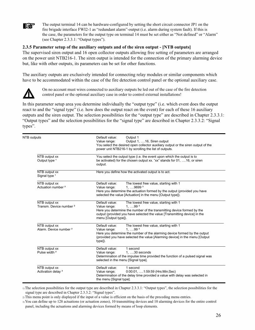
On no account must wires connected to auxiliary outputs be led out of the case of the fire detectioncontrol panel or the optional auxiliary case in order to control external installations!
In this parameter setup area you determine individually the “output type” (i.e. which event does the outputreact to and the “signal type” (i.e. how does the output react on the event) for each of these 16 auxiliaryoutputs and the siren output. The selection possibilities for the “output type” are described in Chapter 2.3.3.1:“Output types” and the selection possibilities for the “signal type” are described in Chapter 2.3.3.2: “Signaltypes”.
1) The selection possibilities for the output type are described in Chapter 2.3.3.1: “Output types”, the selection possibilities for the signal type are described in Chapter 2.3.3.2: “Signal types”.2) This menu point is only displayed if the input of a value is efficient on the basis of the preceding menu entries.3) You can define up to 128 actuations (or actuation zones), 10 transmitting devices and 10 alarming devices for the entire control panel, including the actuations and alarming devices formed by means of loop elements.
2.3.5 Parameter setup of the auxiliary outputs and of the siren output - [NTB outputs]The supervised siren output and 16 open collector outputs allowing free setting of parameters are arrangedon the power unit NTB216-1. The siren output is intended for the connection of the primary alarming devicebut, like with other outputs, its parameters can be set for other functions.
The auxiliary outputs are exclusively intended for connecting relay modules or similar components whichhave to be accommodated within the case of the fire detection control panel or the optional auxiliary case.
The output terminal 14 can be hardware-configured by setting the short circuit connector JP1 on thefire brigade interface FWI2-1 as “redundant alarm”-output (i.e. alarm during system fault). If this isthe case, the parameters for the output type on terminal 14 must be set either as “Not defined” or “Alarm”(see Chapter 2.3.3.1: “Output types”).
NTB outputs Default value: Output 1Value range: Output 1, ….16, Siren outputYou select the desired open collector auxiliary output or the siren output of thepower unit NTB216-1 by scrolling the list of outputs.
NTB output xx You select the output type (i.e. the event upon which the output is toOutput type ¹ be activated) for the chosen output xx. “xx” stands for 01, ….16, or siren
output.
NTB output xx Here you define how the activated output is to act.Signal type ¹
NTB output xx Default value: The lowest free value, starting with 1Actuation number ² Value range: 1, ….9699 ³
Here you determine the actuation formed by the output (provided you haveselected the value [Actuation] in the menu [Output type]).
NTB output xx Default value: The lowest free value, starting with 1Transm. Device number ² Value range: 1, ….99 ³
Here you determine the number of the transmitting device formed by theoutput (provided you have selected the value [Transmitting device] in themenu [Output type]).
NTB output xx Default value: The lowest free value, starting with 1Alarm. Device number ² Value range: 1, ….99 ³
Here you determine the number of the alarming device formed by the output(provided you have selected the value [Alarming device] in the menu [Outputtype]).
NTB output xx Default value: 1 secondPulse width ² Value range: 1, ….30 seconds
Determination of the impulse time provided the function of a pulsed signal wasselected in the menu [Signal type].
NTB output xx Default value: 1 secondActivation delay ² Value range; 0:00:01, ….1:59:59 (Hrs:Min;Sec)
Determination of the delay time provided a value with delay was selected inthe menu [Signal type].
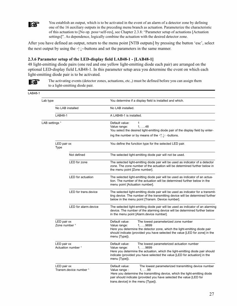
27
You establish an output, which is to be activated in the event of an alarm of a detector zone by definingone of the 16 auxiliary outputs in the preceding menu branch as actuation. Parameterize the characteristicof this actuation to [No op. poss+self-res], see Chapter 2.3.8: “Parameter setup of actuations [Actuationsettings]”. As dependence, logically combine the actuation with the desired detector zone.
After you have defined an output, return to the menu point [NTB outputs] by pressing the button ‘esc’, selectthe next output by using the -buttons and set the parameters in the same manner.
2.3.6 Parameter setup of the LED-display field LAB48-1 - [LAB48-1]48 light-emitting diode pairs (one red and one yellow light-emitting diode each pair) are arranged on theoptional LED-display field LAB48-1. In this parameter setup area you determine the event on which eachlight-emitting diode pair is to be activated.
The activating events (detector zones, actuations, etc.,) must be defined before you can assign themto a light-emitting diode pair.
LAB48-1
Lab type You determine if a display field is installed and which.
No LAB installed No LAB installed.
LAB48-1 A LAB48-1 is installed.
LAB settings ¹ Default value: 1Value range: 1, ….48You select the desired light-emitting diode pair of the display field by enter-
ing the number or by means of the -buttons.
LED pair xx You define the function type for the selected LED pair.Type
Not defined The selected light-emitting diode pair will not be used.
LED for zone The selected light-emitting diode pair will be used as indicator of a detectorzone. The zone number of the actuation will be determined further below inthe menu point [Zone number].
LED for actuation The selected light-emitting diode pair will be used as indicator of an actua-tion. The number of the actuation will be determined further below in themenu point [Actuation number].
LED for trans.device The selected light-emitting diode pair will be used as indicator for a transmit-ting device. The number of the transmitting device will be determined furtherbelow in the menu point [Transm. Device number].
LED for alarm.device The selected light-emitting diode pair will be used as indicator of an alarmingdevice. The number of the alarming device will be determined further belowin the menu point [Alarm.device number].
LED pair xx Default value: The lowest parameterized zone numberZone number ¹ Value range: 1, ….9699
Here you determine the detector zone, which the light-emitting diode pairshould indicate (provided you have selected the value [LED for zone] in themenu [Type]).
LED pair xx Default value: The lowest parameterized actuation numberActuation number ¹ Value range: 1, ….9699
Here you determine the actuation, which the light-emitting diode pair shouldindicate (provided you have selected the value [LED for actuation] in themenu [Type]).
LED pair xx Default value: The lowest parameterized transmitting device numberTransm.device number ¹ Value range : 1, ….99
Here you determine the transmitting device, which the light-emitting diodepair should indicate (provided you have selected the value [LED fortrans.device] in the menu [Type]).
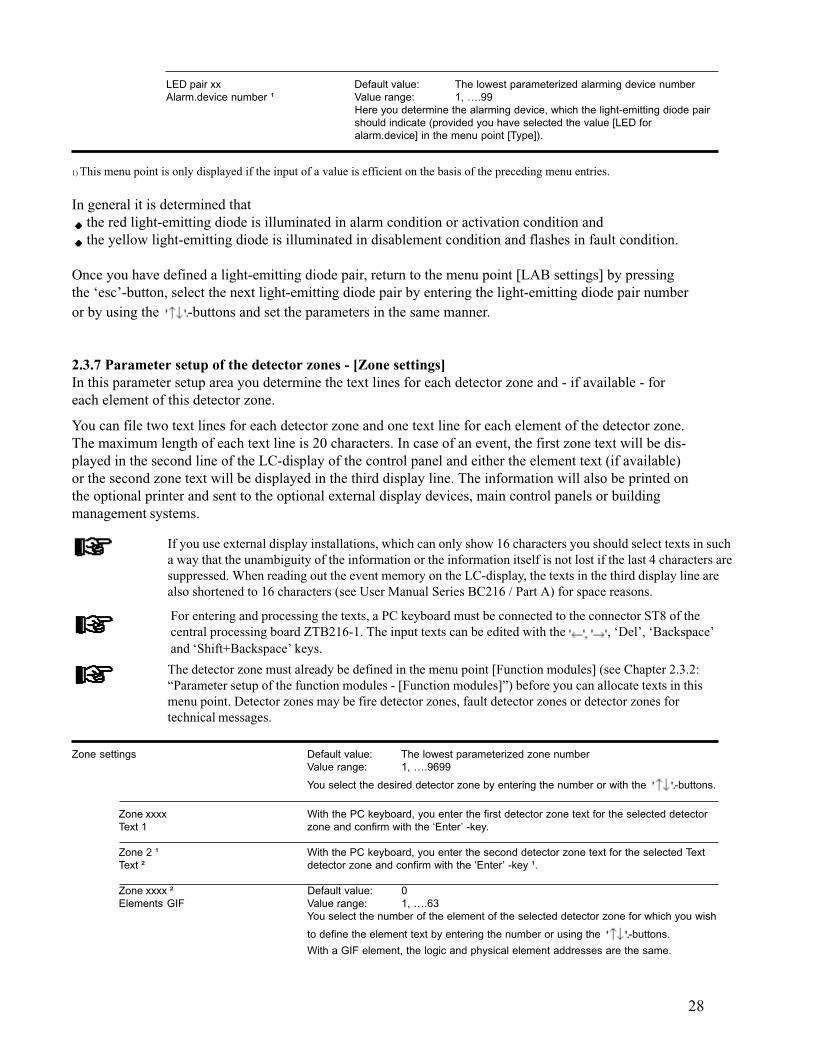
28
You can file two text lines for each detector zone and one text line for each element of the detector zone.The maximum length of each text line is 20 characters. In case of an event, the first zone text will be dis-played in the second line of the LC-display of the control panel and either the element text (if available)or the second zone text will be displayed in the third display line. The information will also be printed onthe optional printer and sent to the optional external display devices, main control panels or buildingmanagement systems.
If you use external display installations, which can only show 16 characters you should select texts in sucha way that the unambiguity of the information or the information itself is not lost if the last 4 characters aresuppressed. When reading out the event memory on the LC-display, the texts in the third display line arealso shortened to 16 characters (see User Manual Series BC216 / Part A) for space reasons.
For entering and processing the texts, a PC keyboard must be connected to the connector ST8 of thecentral processing board ZTB216-1. The input texts can be edited with the , ‘Del’, ‘Backspace’and ‘Shift+Backspace’ keys.
The detector zone must already be defined in the menu point [Function modules] (see Chapter 2.3.2:“Parameter setup of the function modules - [Function modules]”) before you can allocate texts in thismenu point. Detector zones may be fire detector zones, fault detector zones or detector zones fortechnical messages.
LED pair xx Default value: The lowest parameterized alarming device numberAlarm.device number ¹ Value range: 1, ….99
Here you determine the alarming device, which the light-emitting diode pairshould indicate (provided you have selected the value [LED foralarm.device] in the menu point [Type]).
1) This menu point is only displayed if the input of a value is efficient on the basis of the preceding menu entries.
In general it is determined that the red light-emitting diode is illuminated in alarm condition or activation condition and the yellow light-emitting diode is illuminated in disablement condition and flashes in fault condition.
Once you have defined a light-emitting diode pair, return to the menu point [LAB settings] by pressingthe ‘esc’-button, select the next light-emitting diode pair by entering the light-emitting diode pair numberor by using the -buttons and set the parameters in the same manner.
2.3.7 Parameter setup of the detector zones - [Zone settings]In this parameter setup area you determine the text lines for each detector zone and - if available - foreach element of this detector zone.
Zone settings Default value: The lowest parameterized zone numberValue range: 1, ….9699
You select the desired detector zone by entering the number or with the -buttons.
Zone xxxx With the PC keyboard, you enter the first detector zone text for the selected detectorText 1 zone and confirm with the ‘Enter’ -key.
Zone 2 ¹ With the PC keyboard, you enter the second detector zone text for the selected TextText ² detector zone and confirm with the ‘Enter’ -key ¹.
Zone xxxx ² Default value: 0Elements GIF Value range: 1, ….63
You select the number of the element of the selected detector zone for which you wish
to define the element text by entering the number or using the -buttons.
With a GIF element, the logic and physical element addresses are the same.
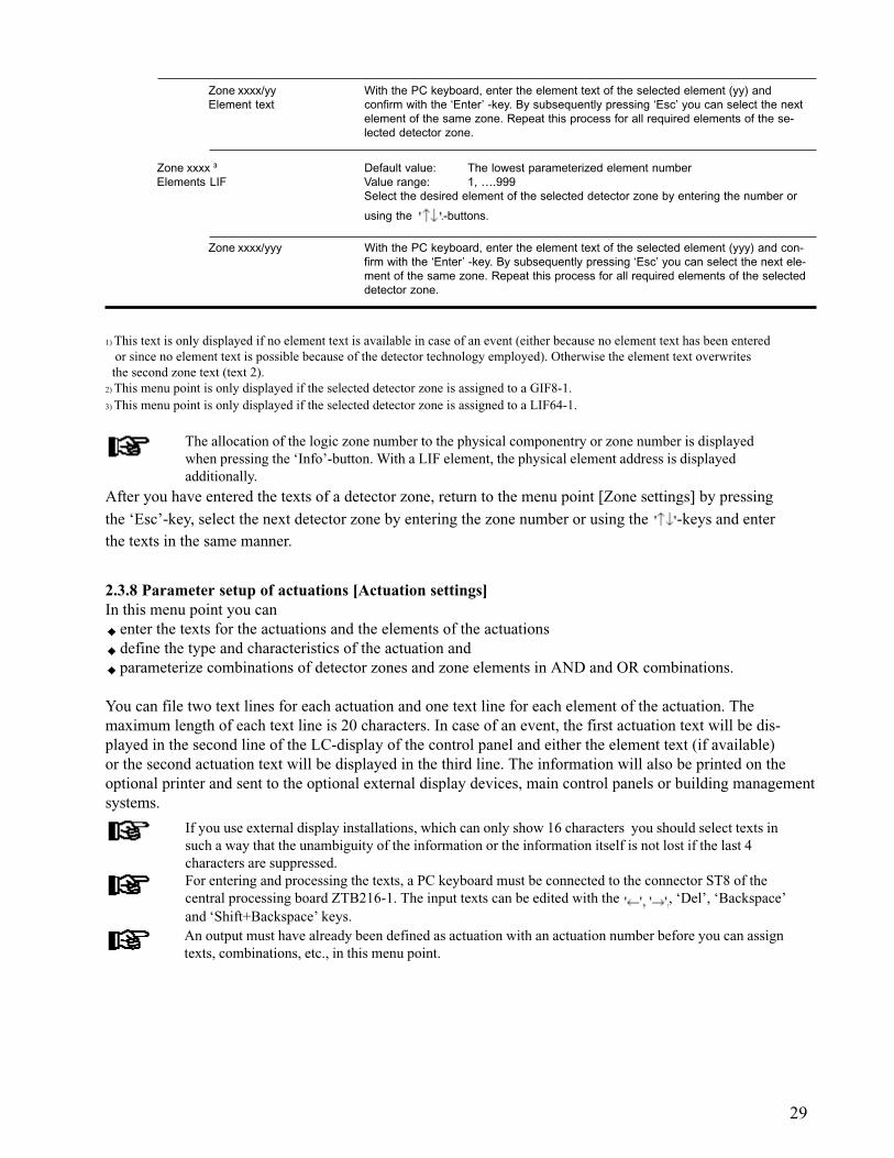
29
1) This text is only displayed if no element text is available in case of an event (either because no element text has been entered or since no element text is possible because of the detector technology employed). Otherwise the element text overwrites the second zone text (text 2).2) This menu point is only displayed if the selected detector zone is assigned to a GIF8-1.3) This menu point is only displayed if the selected detector zone is assigned to a LIF64-1.
The allocation of the logic zone number to the physical componentry or zone number is displayedwhen pressing the ‘Info’-button. With a LIF element, the physical element address is displayedadditionally.
After you have entered the texts of a detector zone, return to the menu point [Zone settings] by pressingthe ‘Esc’-key, select the next detector zone by entering the zone number or using the -keys and enterthe texts in the same manner.
Zone xxxx ³ Default value: The lowest parameterized element numberElements LIF Value range: 1, ….999
Select the desired element of the selected detector zone by entering the number or
using the -buttons.
Zone xxxx/yyy With the PC keyboard, enter the element text of the selected element (yyy) and con-firm with the ‘Enter’ -key. By subsequently pressing ‘Esc’ you can select the next ele-ment of the same zone. Repeat this process for all required elements of the selecteddetector zone.
Zone xxxx/yy With the PC keyboard, enter the element text of the selected element (yy) andElement text confirm with the ‘Enter’ -key. By subsequently pressing ‘Esc’ you can select the next
element of the same zone. Repeat this process for all required elements of the se-lected detector zone.
2.3.8 Parameter setup of actuations [Actuation settings]In this menu point you can
enter the texts for the actuations and the elements of the actuations define the type and characteristics of the actuation and parameterize combinations of detector zones and zone elements in AND and OR combinations.
You can file two text lines for each actuation and one text line for each element of the actuation. Themaximum length of each text line is 20 characters. In case of an event, the first actuation text will be dis-played in the second line of the LC-display of the control panel and either the element text (if available)or the second actuation text will be displayed in the third line. The information will also be printed on theoptional printer and sent to the optional external display devices, main control panels or building managementsystems.
If you use external display installations, which can only show 16 characters you should select texts insuch a way that the unambiguity of the information or the information itself is not lost if the last 4characters are suppressed.For entering and processing the texts, a PC keyboard must be connected to the connector ST8 of thecentral processing board ZTB216-1. The input texts can be edited with the , ‘Del’, ‘Backspace’and ‘Shift+Backspace’ keys.An output must have already been defined as actuation with an actuation number before you can assigntexts, combinations, etc., in this menu point.
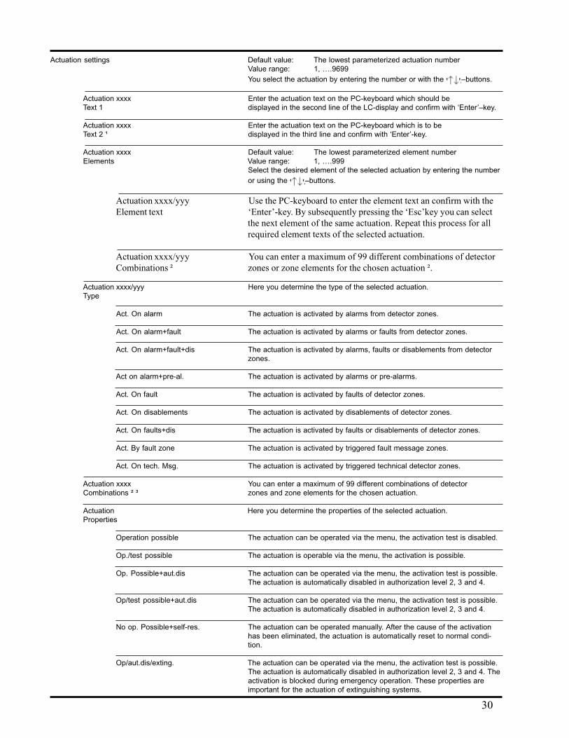
30
Actuation settings Default value: The lowest parameterized actuation numberValue range: 1, ….9699You select the actuation by entering the number or with the –buttons.
Actuation xxxx Enter the actuation text on the PC-keyboard which should beText 1 displayed in the second line of the LC-display and confirm with ‘Enter’–key.
Actuation xxxx Enter the actuation text on the PC-keyboard which is to beText 2 ¹ displayed in the third line and confirm with ‘Enter’-key.
Actuation xxxx Default value: The lowest parameterized element numberElements Value range: 1, ….999
Select the desired element of the selected actuation by entering the numberor using the –buttons.
Actuation xxxx/yyy Use the PC-keyboard to enter the element text an confirm with theElement text ‘Enter’-key. By subsequently pressing the ‘Esc’key you can select
the next element of the same actuation. Repeat this process for allrequired element texts of the selected actuation.
Actuation xxxx/yyy You can enter a maximum of 99 different combinations of detectorCombinations ² zones or zone elements for the chosen actuation ².
Actuation xxxx/yyy Here you determine the type of the selected actuation.Type
Act. On alarm The actuation is activated by alarms from detector zones.
Act. On alarm+fault The actuation is activated by alarms or faults from detector zones.
Act. On alarm+fault+dis The actuation is activated by alarms, faults or disablements from detectorzones.
Act on alarm+pre-al. The actuation is activated by alarms or pre-alarms.
Act. On fault The actuation is activated by faults of detector zones.
Act. On disablements The actuation is activated by disablements of detector zones.
Act. On faults+dis The actuation is activated by faults or disablements of detector zones.
Act. By fault zone The actuation is activated by triggered fault message zones.
Act. On tech. Msg. The actuation is activated by triggered technical detector zones.
Actuation xxxx You can enter a maximum of 99 different combinations of detectorCombinations ² ³ zones and zone elements for the chosen actuation.
Actuation Here you determine the properties of the selected actuation.Properties
Operation possible The actuation can be operated via the menu, the activation test is disabled.
Op./test possible The actuation is operable via the menu, the activation is possible.
Op. Possible+aut.dis The actuation can be operated via the menu, the activation test is possible.The actuation is automatically disabled in authorization level 2, 3 and 4.
Op/test possible+aut.dis The actuation can be operated via the menu, the activation test is possible.The actuation is automatically disabled in authorization level 2, 3 and 4.
No op. Possible+self-res. The actuation can be operated manually. After the cause of the activationhas been eliminated, the actuation is automatically reset to normal condi-tion.
Op/aut.dis/exting. The actuation can be operated via the menu, the activation test is possible.The actuation is automatically disabled in authorization level 2, 3 and 4. Theactivation is blocked during emergency operation. These properties areimportant for the actuation of extinguishing systems.
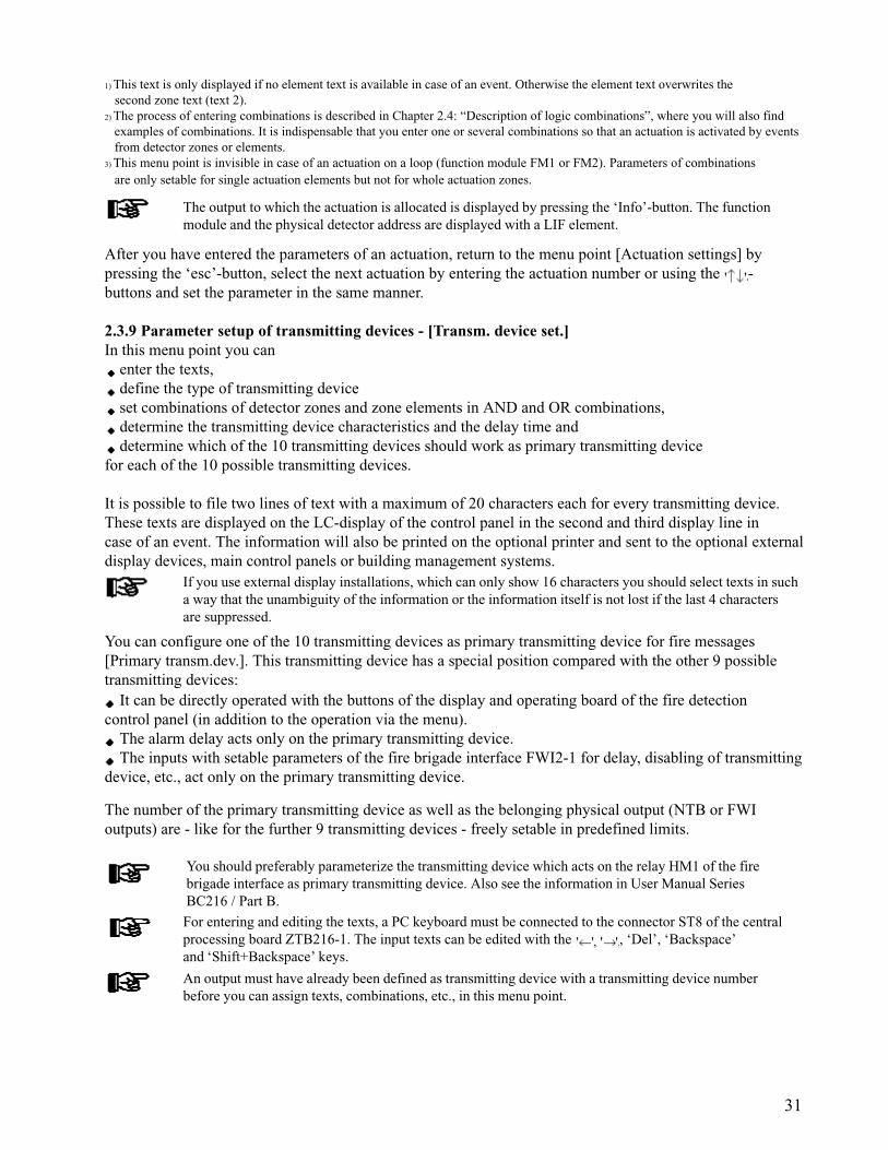
31
1) This text is only displayed if no element text is available in case of an event. Otherwise the element text overwrites the second zone text (text 2).2) The process of entering combinations is described in Chapter 2.4: “Description of logic combinations”, where you will also find examples of combinations. It is indispensable that you enter one or several combinations so that an actuation is activated by events from detector zones or elements.3) This menu point is invisible in case of an actuation on a loop (function module FM1 or FM2). Parameters of combinations are only setable for single actuation elements but not for whole actuation zones.
The output to which the actuation is allocated is displayed by pressing the ‘Info’-button. The functionmodule and the physical detector address are displayed with a LIF element.
After you have entered the parameters of an actuation, return to the menu point [Actuation settings] bypressing the ‘esc’-button, select the next actuation by entering the actuation number or using the -buttons and set the parameter in the same manner.
2.3.9 Parameter setup of transmitting devices - [Transm. device set.]In this menu point you can
enter the texts, define the type of transmitting device set combinations of detector zones and zone elements in AND and OR combinations, determine the transmitting device characteristics and the delay time and determine which of the 10 transmitting devices should work as primary transmitting device
for each of the 10 possible transmitting devices.
It is possible to file two lines of text with a maximum of 20 characters each for every transmitting device.These texts are displayed on the LC-display of the control panel in the second and third display line incase of an event. The information will also be printed on the optional printer and sent to the optional externaldisplay devices, main control panels or building management systems.
If you use external display installations, which can only show 16 characters you should select texts in sucha way that the unambiguity of the information or the information itself is not lost if the last 4 charactersare suppressed.
You can configure one of the 10 transmitting devices as primary transmitting device for fire messages[Primary transm.dev.]. This transmitting device has a special position compared with the other 9 possibletransmitting devices:
It can be directly operated with the buttons of the display and operating board of the fire detectioncontrol panel (in addition to the operation via the menu).
The alarm delay acts only on the primary transmitting device. The inputs with setable parameters of the fire brigade interface FWI2-1 for delay, disabling of transmitting
device, etc., act only on the primary transmitting device.
The number of the primary transmitting device as well as the belonging physical output (NTB or FWIoutputs) are - like for the further 9 transmitting devices - freely setable in predefined limits.
You should preferably parameterize the transmitting device which acts on the relay HM1 of the firebrigade interface as primary transmitting device. Also see the information in User Manual SeriesBC216 / Part B.
For entering and editing the texts, a PC keyboard must be connected to the connector ST8 of the centralprocessing board ZTB216-1. The input texts can be edited with the , ‘Del’, ‘Backspace’and ‘Shift+Backspace’ keys.
An output must have already been defined as transmitting device with a transmitting device numberbefore you can assign texts, combinations, etc., in this menu point.
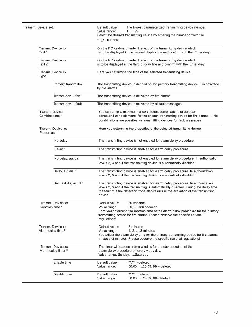
32
Transm. Device set. Default value: The lowest parameterized transmitting device numberValue range: 1, ….99Select the desired transmitting device by entering the number or with the
–buttons.
Transm. Device xx On the PC keyboard, enter the text of the transmitting device whichText 1 is to be displayed in the second display line and confirm with the ‘Enter’-key.
Transm. Device xx On the PC keyboard, enter the text of the transmitting device whichText 2 is to be displayed in the third display line and confirm with the ‘Enter’-key.
Transm. Device xx Here you determine the type of the selected transmitting device.Type
Primary transm.dev. The transmitting device is defined as the primary transmitting device, it is activatedby fire alarms.
Transm.dev. – fire The transmitting device is activated by fire alarms.
Transm.dev. – fault The transmitting device is activated by all fault messages.
Transm. Device You can enter a maximum of 99 different combinations of detectorCombinations ¹ zones and zone elements for the chosen transmitting device for fire alarms ¹. No
combinations are possible for transmitting devices for fault messages.
Transm. Device xx Here you determine the properties of the selected transmitting device.Properties
No delay The transmitting device is not enabled for alarm delay procedure.
Delay ³ The transmitting device is enabled for alarm delay procedure.
No delay, aut.dis The transmitting device is not enabled for alarm delay procedure. In authorizationlevels 2, 3 and 4 the transmitting device is automatically disabled.
Delay, aut.dis ³ The transmitting device is enabled for alarm delay procedure. In authorizationlevels 2, 3 and 4 the transmitting device is automatically disabled.
Del., aut.dis, act/flt ³ The transmitting device is enabled for alarm delay procedure. In authorizationlevels 2, 3 and 4 the transmitting is automatically disabled. During the delay timethe fault of a fire detection zone also results in the activation of the transmittingdevice.
Transm. Device xx Default value: 30 seconds Reaction time ² Value range: 20, ….120 seconds
Here you determine the reaction time of the alarm delay procedure for the primary transmitting device for fire alarms. Please observe the specific nationalregulations!
Transm. Device xx Default value: 5 minutes Alarm delay time ² Value range: 1, 2, ….8 minutes
You adjust the alarm delay time for the primary transmitting device for fire alarmsin steps of minutes. Please observe the specific national regulations!
Transm. Device xx The timer will expose a time window for the day operation of the Alarm delay timer ² alarm delay procedure on every week day.
Value range: Sunday, ….Saturday
Enable time Default value: **:** (=deleted)Value range: 00:00, ….23:59, 99 = deleted
Disable time Default value: **:** (=deleted)Value range: 00:00, ….23:59, 99=deleted
33
1) The process for entering combinations is described in Chapter 2.4: “Description of logic combinations”, where you will also find examples of such combinations. If no combination is entered for a transmitting device, this transmitting device will be activated by every fire alarm of a detector zone. This menu point does not appear when setting the parameters for “Transm.dev. - fault”.2) This menu point appears only when parameterizing as primary transmitting device and when the alarm delay was additionally enabled in the menu [Property].3) This selection option appears only with the primary transmitting device.4) By deleting one of the two switching times of a day by entering 99 as hourly value, the second switching time of the day is also deleted. On the LC-display, this will be confirmed with the message [Timer entries deleted]. A deleted time is indicated by “**.**”. Switching times can be deleted on the PC keyboard also by using the ‘Del’-key.
Notice the following special cases when entering the times of the alarm delay timer: The switching times of a day are deleted: the alarm delay is generally enabled for this day, switching
between day and night operation is possible at any time. The switching times of a day are defined but exactly equal (e.g., enable time = 00:00, disable time =
00:00): the alarm delay is generally locked for this day, switching to day operation is impossible, anincoming alarm message is forwarded undelayedly.
The function area “alarm delay” is described in detail in User Manual Series BC216 / Part A.
The duration of the alarm delay time must be coordinated with the responsible authorities.
Pressing the ‘Info’-key will show, which output the transmitting device is assigned to.
Once you have entered the parameters of the transmitting device you return to the menu point [Transm.device set.] by pressing the ‘esc’-button, select the next transmitting device by entering the transmittingdevice number or with the -buttons and set the parameters in the same manner.
2.3.10 Parameter setup of alarming devices [Alarming device set.]In this menu point you can
enter the display texts and determine combinations of detector zones in AND and OR combinations and define the properties
for each of the 10 possible alarming devices.
For each alarming device you can file two lines of text with a maximum of 20 characters each. In case ofan event, the texts of the alarming device will be displayed on the control panel in the second and thirddisplay line. The information will also be printed on the optional printer and sent to the optional externaldisplay devices, main control panels or building management systems.
If you use external display installations, which can only show 16 characters you should select texts in sucha way that the unambiguity of the information or the information itself is not lost if the last 4 charactersare suppressed.
The primary alarming device holds a special position compared with the further 9 possible alarmingdevices:
If the siren output of the power unit NTB216-1 was parameterized as alarming device (thereto seeChapter 2.3.3.1: “Output types”), this alarming device will automatically become primary alarming device.Has the siren output been parameterized for another function, no primary alarming device will exist in thecontrol panel.
Additionally to the operation via the menu it can be operated directly with the buttons of the displayand operating board of the fire detection control panel.
The number of the primary alarming device is - like for the further 9 alarming devices - freely setable inpredefined limits.
34
All additional alarming devices must be activated by way of optional componentries (e.g., relay modules),the operation of these alarming devices is exclusively made by the menu.
For entering and editing the texts, a PC keyboard must be connected to the connector ST8 of the centralprocessing board ZTB216-1. The entered texts can be edited with the , ‘Del’, ‘Backspace’and ‘Shift+Backspace’ keys.An output must have already been defined as alarming device with an alarming device number beforeyou can assign texts, combinations, etc., in this menu point.
1) The process of entering combinations is described in Chapter 2.4: “Description of logic combinations”, where you will also find examples of combinations. If you do not enter a combination for an alarming device, this alarming device will be activated with every alarm from a fire detector zone.2) This is valid for the primary alarming device only.3) This is valid for all alarming devices, except for the primary alarming device.
Pressing the ‘Info’-key will show, which output the alarming device is assigned to. If the alarmingdevice is realized via a loop element, the function module and the physical address will be displayed.
Alarming device set. Default value: The lowest parameterized alarming device number
Value range: 1, ….99You select the desired alarming device by entering the number or with the
–buttons.
Alarming device xx Enter the text on the PC keyboard which should be displayed in the Text 1second display line and confirm with the ‘Enter’-key.
Alarming device xx Enter the text on the PC keyboard which is to be displayed in the Text 2third display line and confirm with the ‘Enter’-key.
Alarming device xx You can enter a maximum of 99 different combinations of detector Combi-nations ¹ zones and zone elements for the chosen alarming device ¹.
Alarming device xx Here you determine the properties of the selected alarming device.Properties
N. silence/n. retrig. ² The activated alarming device can be silenced in authorization level 2, 3and 4 only and will not be activated renewedly by sequential alarms oncebeen silenced.
Silence/n. retrigger ² The activated alarming device can be silenced in authorization level 1 alsoand will not be activated renewedly by sequential alarms once being silenced.
N. silence/retrigger ² The activated alarming device can be silenced in authorization level 2, 3and 4 only and will be activated renewedly by sequential alarms once beensilenced.
Silence/retrigger ² The activated alarming device can be silenced in authorization level 1 alsoand will be activated renewedly by sequential alarms once being silenced.
Not retrriggerable ³ The alarming device will not be activated renewedly by sequential alarmsonce being silenced via the menu.
Retriggerable ³ The alarming device will be activated renewedly by sequential alarms oncebeing silenced via the menu.
Once you have entered the parameters of the alarming device you return to the menu point [Alarming deviceset.] by pressing the ‘esc’-button, select the next alarming device by entering the number or using the
-buttons and set the parameters in the same manner.
35
As an option it is possible to use two RS232-C interfaces for the connection of additional equipment bymeans of the serial interface modules SIM216-1 and SIM216-2. Both serial interfaces are also capable ofconnecting a printer but the connection of only one printer to the control panel is permitted.
If you have not connected any device to the INFO bus and have not installed an additional serial interfacemodule, you can completely skip this menu point.
2.3.11 Parameter setup of the interfaces - [Interfaces]In this menu point you can
configure the INFO bus and determine the type, baud rate and the printer filter (if the parameters are set for a printer)
for both serial interfaces.
The INFO bus connection for the control of a maximum of 8 additional devices of the system (such asdisplay devices, remote indication unit, transmitting devices, etc.) is included in the fire detection controlpanel BC216-1 as standard.
Interfaces
INFO-bus
INFO-bus Default value: 0Number of devices Value range: 0, ….8
Here you enter the number of devices connected to the INFO-bus.
INFO-bus Default value: 1200 baudBaudrate Value range: 600, 1200, 2400 baud
Change the default value only in exceptional cases and only afterconsultation with the manufacturer.
Serial interface Default value: 1Value range: 1, 2You select the serial interface whose parameters are to be set:1=SIM216-x on connector ST6 of the ZTB216-12=SIM216-x on connector ST7 of the ZTB216-1.
Ser. Interface x Here you determine the type of serial interface.Type
Not defined The serial interface will not be used.
PARSOFT A PC for setting the parameters of the control panel with theparameter setup software PARSOFT is connected to the serialinterface. The baud rate is 38400 baud.
Printer, no superv. The device connected to the serial interface will not be monitored bythe control panel. The data will be transferred irrespective ofwhether the device is ready for receiving. This setting is suitable,e.g. for connecting a data terminal.
Printer, with superv. The printer connected to the serial interface is monitored by thecontrol panel for the reaction to the handshake line CTS. Only theserial interface module SIM216-1 is suitable for this! Both shortcircuit connectors on SIM216-1 must be set to CTS (workssettings).
Ser. Interface x Default value: 1200 baudBaudrate ³ Value range: 1200, 2400, 4800, 9600, 38400, 57600 baud
Ser. Interface x Filter for selection of the printing data.Printer filter ¹
Print all All events are printed without filter.
Control panel Only control panel events will be printed.
Detection zones Only detector zone events will be printed.
36
In the sub-menu [Initialize new componentries], only the configuration for additionally installedcomponentries will be automatically created. The system configuration for existing componentries and of nolonger available componentries remains untouched.
In the sub-menu [Delete settings and initialize componentries], all settings are deleted and set to defaultvalues in accordance with the installed componentries. With this menu point you are able to reset a parametersetup, which has got “out of tune” through frequent changing, to safe values and subsequently begin with anew parameter setup.
Following the initialisation you can continue with the parameter setup. For the new parameters to becomeeffective, you have to exit authorisation, which will restart the control panel.
During a restart, all current events are reset, including alarm and fault messages. Disablements ofcontrol panel parts will not be changed. During the restart, the control panel is out of function forapproximately 5 seconds.
The deletion of the system configuration cannot be undone! Therefore, the entry of the installer codeis requested once again prior to the deletion, for reasons of safety. You can prematurely exit the submenupoint by pressing the ‘esc’-button.
2.4 Description of logic combinationsFor each actuation, each transmitting device for fire messages and each alarming device of the fire detectioncontrol panel you can determine 99 logic activation combinations, thereby practically performing any neces-sary control task of a modern fire detection system without additional hardware expenditure. The totalnumber of logic combination entries in the memory of the control panel is restricted to 128.
1) This menu point is only displayed if the serial interface was parameterized as “Printer”. A printer filter acts on the event print-out (print-out of continuously incoming events) as well as on the service print-out (print-out of the complete event memory).2) This selection possibility is only visible while setting the parameters of plug-in port ST7 (serial interface 2) of the central processing board ZTB216-2.3) This menu point is invisible if the serial interface was parameterized to [PARSOFT]. The baud rate is fixed to 38400 baud in this case.4) A software update of the software PL149 of the central processing board can only be made via a SIM216-1 plugged to connector ST6.
2.3.12 Automatic setup of the System configuration - [AUTO-setup]In this menu point, you will start a query of the installed hardware and determine their system configurationaccording to the default values assigned by the factory (see Chapter 2.5: “Standard parameter setup withAUTO-setup”).
AUTO-setup
Initialize newComponentries
Start initialization: After confirming with the ‘Enter’, the standard configuration for newly addedcomponentries will be established.
Delete settingsAnd initializeComponentries
Delete all? Following the entry of the installer code and confirming with ‘Enter’,Input authorization- the entire configuration is deleted and re-established in accordanceCode: with the installed componentries.
37
No logic combinations can be determined for a transmitting device, the parameters of which were setfor fault messages.
The special case of alarm activation of a fire detection control panel in an interdependence of two detectorsis not called combination in the sense of this chapter. Detailed information on interdependenciesof two detectors can be found in Chapter 2.3.2.2: “Parameter setup of a loop interface LIF64-1" and inthe User Manual Series BC216 / Part A.
2.4.1 GeneralActuations, transmitting devices and alarming devices are always activated by alarms from detectorzones or elements. By setting the parameters of the logic combinations of these devices you determine thelogic dependencies of the detector zone messages which will activate these devices.
The following possibilities of forming logic combinations are available: OR combination of detector zones and elements entered individually or as a combined range (from detector
zone/element to detector zone/element), “multiple” combination of detector zones and elements entered individually or as a combined range.
In this case the condition “multiple” means: The logic combination condition is fulfilled when morethan one of the detector zones or elements involved are in the state of alarm. Such a logic combinationis used if a particularly high degree of safety against false activation (e.g., of an extinguishing system)is demanded.
Please observe official directives when employing a “multiple” condition.
These two possibilities themselves are again connected by OR combination. The “multiple” combinationis - as shown in the following paragraphs - processed differently by the control panel for transmitting devices,alarming devices and actuations.
2.4.2 Logic combinations for transmitting devices and alarming devicesEach transmitting device for fire alarms and each alarming device - provided no other parameter setuphas been determined - will always be activated by an alarm from every detector zone (or its element) definedas fire detector zone.
You can restrict this general activation by entering logic combinations as follows: If one or several OR combinations have been entered, the activation is performed only by the alarms
contained in the OR combination(s). Alarms outside these combinations will not result in an activation.Explanatory example:The control panel is equipped with 8 fire detector zones (1, ..., 8).The OR combination {1 or 2 or 3} has been entered for the transmitting device Nr. 2. The transmittingdevice Nr. 2 is activated only if alarm is signalled from at least one detector zone of {1, 2, 3}.Alarms from the detector zones 4, ..., 8 do not have any effect on the transmitting device Nr. 2.
If one or several “multiple” combinations have been entered, activation will take place both when thelogic combination condition is fulfilled and with an alarm from detector zones and elements locatedoutside these “multiple” combinations.
Explanatory example:The control panel is equipped with 8 fire detector zones (1, ..., 8).The “multiple” combination {4, 5, 6} has been entered for the transmitting device Nr. 3.The transmitting device Nr. 3 is activated when- alarm is signalled from at least two detector zones of {4, 5, 6} or- if one (or several) detector zones from the zones 1, 2, 3, 7, 8 signal alarm.
38
You cannot enter general combinations which define the activation condition for the complete actuation zonefor actuations which were parameterized as a zone of single actuation elements (i.e. of control modules on theloop) of a function module. You have to enter the desired combinations separately for every single actuationelement of the zone.
The combinations of the single elements of an actuation zone need not be identical. For example, youcan define an actuation zone whose elements are activated by different events (or combinations ofevents). The operation and displaying on the control panel is however made for the complete actuationzone.
The following combinations are possible: If one or several OR combinations have been entered, the activation is performed only through the
alarms contained in the OR combination(s). Alarms outside these logic combinations will not result inan activation.
Explanatory example:The control panel is equipped with 8 fire detector zones (1, ..., 8).The OR combination {1} has been entered for the actuation Nr. 2.The actuation Nr. 2 will only be activated if the detector zone Nr. 1 signals alarm.Alarms from the detector zones 2, ..., 8 will not have any effect on the actuation Nr. 2.
If one or several “multiple” combinations have been entered, the activation will take place when thecombination condition has been fulfilled. Alarms from detector zones and elements located outsidethese “multiple” combinations will not result in an activation.
Explanatory example:The control panel is equipped with 8 fire detector zones (1, ..., 8).The “multiple” combination {4, 5} has been entered for the actuation Nr. 3.The actuation Nr. 3 is activated when both detector zones 4 and 5 are in the state of alarm. If onlyone of the two detector zones is in the state of alarm, the actuation Nr. 2 is not activated. No activationtakes place either upon alarm from the detector zones 1, 2, 3, 6, 7, 8.
If “multiple” combinations and OR combinations are entered jointly, the activation takes place bothwhen one of these “multiple” combinations has been fulfilled and also by the alarms included in theOR combinations. Alarms from detector zones outside these combinations will not result in an activationin this case.
If “multiple” combinations and OR combinations are entered jointly, the activation takes place bothwhen one of these “multiple” combinations has been fulfilled and also by the alarms included in theOR combinations. Alarms from detector zones and elements outside these logic combinations will notresult in activation in this case.
Explanatory example:The control panel is equipped with 8 fire detector zones (1, ..., 8).The “multiple” combination {1, 2, 3} and the OR combination {4 or 5} have been entered for thetransmitting device Nr. 4.The transmitting device Nr. 4 is activated- when at least two detector zones from {1, 2, 3} signal alarm, or- if one (or both) detector zones from the zones {4, 5} signal alarm.Alarms from the detector zones 6, 7 and 8 will not result in activation of the transmitting device Nr. 4.
2.4.3 Logic combinations for actuations and actuation elementsContrary to transmitting devices and alarming devices, an action is only set for actuations if this is expresslyspecified by the entered combinations of detector zones and elements. If no logic combinations are enteredfor an actuation, the actuation will never be activated!
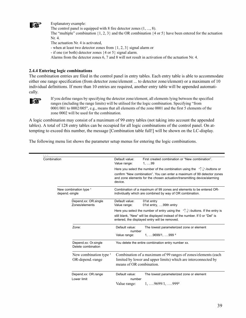
39
Explanatory example:The control panel is equipped with 8 fire detector zones (1, ..., 8).The “multiple” combination {1, 2, 3} and the OR combination {4 or 5} have been entered for the actuationNr. 4.The actuation Nr. 4 is activated,- when at least two detector zones from {1, 2, 3} signal alarm or- if one (or both) detector zones {4 or 5} signal alarm.Alarms from the detector zones 6, 7 and 8 will not result in activation of the actuation Nr. 4.
2.4.4 Entering logic combinationsThe combination entries are filed in the control panel in entry tables. Each entry table is able to accommodateeither one range specification (from detector zone/element ... to detector zone/element) or a maximum of 10individual definitions. If more than 10 entries are required, another entry table will be appended automati-cally.
If you define ranges by specifying the detector zone/element, all elements lying between the specifiedranges (including the range limits) will be utilised for the logic combination. Specifying “from0001/001 to 0002/005", e.g., means that all elements of the zone 0001 and the first 5 elements of thezone 0002 will be used for the combination.
A logic combination may consist of a maximum of 99 entry tables (not taking into account the appendedtables). A total of 128 entry tables can be occupied for all logic combinations of the control panel. On at-tempting to exceed this number, the message [Combination table full!] will be shown on the LC-display.
The following menu list shows the parameter setup menus for entering the logic combinations.
. . .Combination Default value: First created combination or “New combination”.
Value range: 1, ….99
Here you select the number of the combination using the -buttons or
confirm “New combination”. You can enter a maximum of 99 detector zonesand zone elements for the chosen actuation/transmitting device/alarmingdevice.
New combination type ¹ Combination of a maximum of 99 zones and elements to be entered OR-depend.-single individually which are combined by way of OR combination.
Depend.xx: OR.single Default value: 01st entryZones/elements Value range: 01st entry, ….99th entry
Here you select the number of entry using the -buttons. If the entry is
still blank, “New” will be displayed instead of the number. If 0 or “Del” isentered, the displayed entry will be removed.
Zone: Default value: The lowest parameterized zone or elementnumber
Value range: 1, ….9699/1, ….999 ²
Depend.xx: Or.single You delete the entire combination entry number xx.Delete combination
New combination type ¹ Combination of a maximum of 99 ranges of zones/elements (eachOR-depend.-range limited by lower and upper limits) which are interconnected by
means of OR combination.
Depend.xx: OR.range Default value: The lowest parameterized zone or element
Lower limit number
Value range: 1, ….9699/1, ….999²
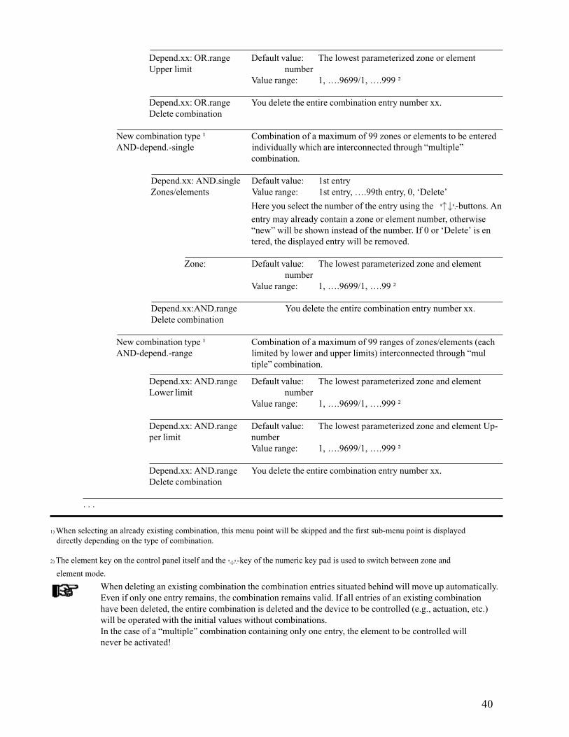
40
When deleting an existing combination the combination entries situated behind will move up automatically.Even if only one entry remains, the combination remains valid. If all entries of an existing combinationhave been deleted, the entire combination is deleted and the device to be controlled (e.g., actuation, etc.)will be operated with the initial values without combinations.In the case of a “multiple” combination containing only one entry, the element to be controlled willnever be activated!
1) When selecting an already existing combination, this menu point will be skipped and the first sub-menu point is displayed directly depending on the type of combination.
2) The element key on the control panel itself and the -key of the numeric key pad is used to switch between zone and
element mode.
Depend.xx: OR.range Default value: The lowest parameterized zone or elementUpper limit number
Value range: 1, ….9699/1, ….999 ²
Depend.xx: OR.range You delete the entire combination entry number xx.Delete combination
New combination type ¹ Combination of a maximum of 99 zones or elements to be enteredAND-depend.-single individually which are interconnected through “multiple”
combination.
Depend.xx: AND.single Default value: 1st entryZones/elements Value range: 1st entry, ….99th entry, 0, ‘Delete’
Here you select the number of the entry using the -buttons. An
entry may already contain a zone or element number, otherwise“new” will be shown instead of the number. If 0 or ‘Delete’ is entered, the displayed entry will be removed.
Zone: Default value: The lowest parameterized zone and elementnumber
Value range: 1, ….9699/1, ….99 ²
Depend.xx:AND.range You delete the entire combination entry number xx.Delete combination
New combination type ¹ Combination of a maximum of 99 ranges of zones/elements (eachAND-depend.-range limited by lower and upper limits) interconnected through “mul
tiple” combination.
Depend.xx: AND.range Default value: The lowest parameterized zone and elementLower limit number
Value range: 1, ….9699/1, ….999 ²
Depend.xx: AND.range Default value: The lowest parameterized zone and element Up-per limit number
Value range: 1, ….9699/1, ….999 ²
Depend.xx: AND.range You delete the entire combination entry number xx.Delete combination
. . .

41
The following examples serve to explain the method of such combinations in more detail:Example 1: Required is the activation of the actuation Nr. xxxx by- the detector zones 0010, 0012, or 0013 in OR combination- or the detector zones 0020, 0021, 0022, 0023 or 0024 in OR combination- or the detector zones 0005 and 0006 in “multiple” combination = two-zone dependency- or the detector zones 0030, 0031, 0032 and 0033 in “multiple” combination.
For this task proceed as follows: As combination Nr. 01 you determine the detector zones 0010, 0012 and 0013 one after the other using
the menu point [OR-depend.-single]. As combination Nr. 02 you determine the value for [Lower limit] with 0020 and the value for [Upper
limit] with 0024 using the menu point [OR-depend.-range]. As combination Nr. 03 you determine the detector zones 0005 and 0006 one after the other using the
menu point [AND-depend.-single]. As combination Nr. 04 you determine the value for [Lower limit] with 0030 and the value for [Upper
limit] with 0033 using the menu point [AND-depend.-range].
Alternatively, you also can combine above combinations 01 and 02 by successively entering detectorzones 0010, 0012, 0013, 0020, 0021, 0022, 0023 and 0024 in menu point [OR-combinat.-single].
Example 2: Required is the activation of the actuation Nr. xxxx, if more than one detector zone of thedetector zones 0010, 0011, 0012, 0013 are in the state of alarm.
For this task proceed as follows: As combination Nr. 01, determine the detector zones 0010 as [Lower limit] and the detector zone
0013 as [Upper limit] using the menu point [AND-depend.-range].
Example 3: Required is the activation of the actuation Nr. xxxx by the elements (= detectors) /004, ...,/008 of the detector zone 0003 in OR combination.
For this task proceed as follows: As combination Nr. 01, determine the element 0003/004 as [Lower limit] and the element 0003/008 as
[Upper limit] using the menu point [AND-depend.-range].
2.5 Standard parameter setup with AUTO-setupThe fire detection control panel BC216-1 is always delivered ex factory without componentry parametersetup. As part of commissioning, you therefore have to establish the necessary configuration either bymeans of individual parameter setting or by means of AUTO-setup.
By calling up the menu point [Parameter settings] - [AUTO-setup] - [Delete settings and initializecomponentries](see Chapter 2.3.12: “Automatic setup of the System configuration - [AUTO-setup]”) thecontrol panel parameters are set to the default values in accordance with the hardware configuration. Typi-cally, you will call up this menu point when commissioning the fire detection control panel BC216-1 for thefirst time.
Calling up the menu point [Parameter settings] - [AUTO-setup] - [Delete settings and initialize componentries]does not only result in new initialisation of the hardware components but also resets all control panelparameters to the default values. Thereby, the entire existing site-specific parameter setup will be deleted.
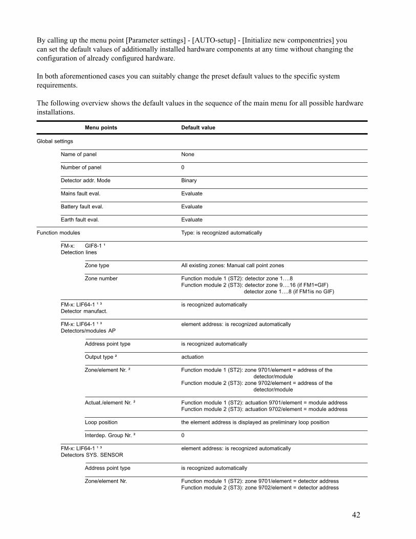
42
By calling up the menu point [Parameter settings] - [AUTO-setup] - [Initialize new componentries] youcan set the default values of additionally installed hardware components at any time without changing theconfiguration of already configured hardware.
In both aforementioned cases you can suitably change the preset default values to the specific systemrequirements.
The following overview shows the default values in the sequence of the main menu for all possible hardwareinstallations.
Menu points Default value
Global settings
Name of panel None
Number of panel 0
Detector addr. Mode Binary
Mains fault eval. Evaluate
Battery fault eval. Evaluate
Earth fault eval. Evaluate
Function modules Type: is recognized automatically
FM-x: GIF8-1 ¹Detection lines
Zone type All existing zones: Manual call point zones
Zone number Function module 1 (ST2): detector zone 1….8Function module 2 (ST3): detector zone 9….16 (if FM1=GIF)
detector zone 1….8 (if FM1is no GIF)
FM-x: LIF64-1 ¹ ³ is recognized automaticallyDetector manufact.
FM-x: LIF64-1 ¹ ³ element address: is recognized automaticallyDetectors/modules AP
Address point type is recognized automatically
Output type ² actuation
Zone/element Nr. ² Function module 1 (ST2): zone 9701/element = address of thedetector/module
Function module 2 (ST3): zone 9702/element = address of thedetector/module
Actuat./element Nr. ² Function module 1 (ST2): actuation 9701/element = module addressFunction module 2 (ST3): actuation 9702/element = module address
Loop position the element address is displayed as preliminary loop position
Interdep. Group Nr. ² 0
FM-x: LIF64-1 ¹ ³ element address: is recognized automaticallyDetectors SYS. SENSOR
Address point type is recognized automatically
Zone/element Nr. Function module 1 (ST2): zone 9701/element = detector addressFunction module 2 (ST3): zone 9702/element = detector address
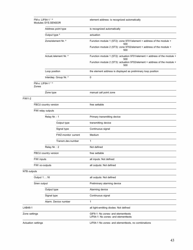
43
FM-x: LIF64-1 ¹ ² element address: is recognized automaticallyModules SYS.SENSOR
Address point type is recognized automatically
Output type ² actuation
Zone/element Nr. ² Function module 1 (ST2): zone 9701/element = address of the module +500
Function module 2 (ST3): zone 9702/element = address of the module +500
Actuat./element Nr. ² Function module 1 (ST2): actuation 9701/element = address of the module +500
Function module 2 (ST3): actuation 9702/element = address of the module +500
Loop position the element address is displayed as preliminary loop position
Interdep. Group Nr. ² 0
FM-x: LIF64-1 ¹ ³Zones
Zone type manual call point zone
FWI1-2
FBCU country version free settable
FWI relay outputs
Relay Nr. : 1 Primary transmitting device
Output type transmitting device
Signal type Continuous signal
FWZ-monitor current Medium
Transm.dev.number 1
Relay Nr. : 2 Not defined
FBCU country version free settable
FWI inputs all inputs: Not defined
FWI oc-outputs all outputs: Not defined
NTB outputs
Output 1….16 all outputs: Not defined
Siren output Preliminary alarming device
Output type Alarming device
Signal type Continuous signal
Alarm. Device number 1
LAB48-1 all light-emitting diodes: Not defined
Zone settings GIF8-1: No zones- and elementtextsLIF64-1: No zones- and elementtexts
Actuation settings LIF64-1 No zones- and elementtexts, no combinations
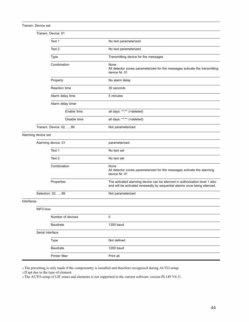
44
1) The presetting is only made if the componentry is installed and therefore recognized during AUTO-setup.2) If apt due to the type of element.3) The AUTO-setup of LIF zones and elements is not supported in the current software version PL149 V4.11.
Transm. Device set.
Transm. Device: 01
Text 1 No text parameterized
Text 2 No text parameterized
Type Transmitting device for fire messages
Combination NoneAll detector zones parameterized for fire messages activate the transmittingdevice Nr. 01
Property No alarm delay
Reaction time 30 seconds
Alarm delay time 5 minutes
Alarm delay timer
Enable time all days: **:** (=deleted)
Disable time all days: **:** (=deleted)
Transm. Device: 02, ….99 Not parameterized
Alarming device set.
Alarming device: 01 parameterized
Text 1 No text set
Text 2 No text set
Combination NoneAll detector zones parameterized for fire messages activate the alarmingdevice Nr. 01
Properties The activated alarming device can be silenced in authorization level 1 alsoand will be activated renewedly by sequential alarms once being silenced.
Selection: 02, ….99 Not parameterized
Interfaces
INFO-bus
Number of devices 0
Baudrate 1200 baud
Serial interface
Type Not defined
Baudrate 1200 baud
Printer filter Print all

45
Printer setting information is found in Chapter 2.3.11: “Parameter setup of the interfaces- [Interfaces]”.
2.6 Settings print-outBy calling up the menu point [System] - [Print-out] - [Settings print-out] (see User Manual Series BC216/ Part A, description of the menu point [System]) you will start the print-out of the parameterized configura-tion of the fire detection control panel BC216-1 on the connected printer. All parameters of the controlpanel will be clearly printed out.
The printer is switched automatically to event print-out - the print-out of all continuously incomingevents - after finishing the configuration print-out.

46
3 Parameter setup by means of PC and software PARSOFT-1If you have a PC (notebook) at your disposal, you can carry out the parameter setup for the fire detectioncontrol panel BC216-1 considerably easier, clearer and faster than is possible with the method using controlpanel keypad or PC keyboard with the built-in LC-display described in the preceding chapter. With theparameter setup software PARSOFT-1 you can
read the set parameter data of a control panel into the PC, change the data on the PC to suit the requirements and load the new data from the PC back into the control panel.
You can further save the data of the control panel on the PC or on independent storage media, create the setup data independently from the control panel on the PC and subsequently load the data in
the control panel, copy the setup data of one control panel to another, etc.
The parameter setup software is exclusively designed for rapid and simple parameter setup of the firedetection control panel BC216-1 but not for the operation and remote maintenance of the control panel!
During all activities performed via PARSOFT-1 the fire detection control panel BC216-1 keeps workingwith the hitherto parameters in the authorization level selected on the control panel unaffectedly fromPARSOFT-1. Only after loading a new setup from the PC to the control panel, the control panel performsa restart and subsequently starts to work in authorization level 1 with the new parameters.
The authorization level selected on the fire detection control panel BC216-1 is insignificant for activitiesperformed via PARSOFT-1; you must prove your authorization for changing parameters by entering yourinstaller code via PARSOFT-1. Nevertheless, it is recommended to set the control panel in authorizationlevel 1 before starting to work with PARSOFT-1.
The authorization level on the control panel must not be changed during data transfer from the PC tothe control panel or from the control panel to the PC!
3.1 Installation of the parameter setup software PARSOFT-1You require an IBM-compatible PC with Windows 95/98/NT4.0/2000 as operating system and the followingminimum requirements:
Processor Pentium or equivalent /100MHz, 32MB RAM, At least 5MB free storage capacity on a hard disk, CD ROM drive, free serial interface with 9-pin connector, keyboard, mouse, optional: printer.
The parameter setup software PARSOFT-1, Art. Nr. 218007 (German/English/Spanish), is supplied on aCD ROM. The software package is not copy-protected; nevertheless, usage of the programme is subject to thelicense agreement saved on the CD.
If you are accepting the license agreement, start the installation by entering <CD-ROM-D>:\<Language>\Setup in the Windows input field “Execute”, the installation process will then take placeautomatically (<CD-ROM-D> stands for the drive name of your CD-ROM drive, <Language> stands for thelanguage version: currently, “Deutsch” (German), “English” and “Español” (Spanish) are provided). Asdefault, the programmes will be installed in C:\Programme\Parsoft but you can determine an individual path ifyou wish.

47
When starting the programme the first time, you are asked via a dialogue box to enter the CD key whichis found on the CD label. At correct entry the key is saved in the system area of the PC and the programme isstarted.
A serial interface module SIM216-1 must be installed in the fire detection control panel BC216-1, thecorresponding interface of the BC216-1 must be set to “PARSOFT” (see Chapter 2.3.11: “Parameter setup ofthe interfaces - [Interfaces]”). An interface cable as described in User Manual Series BC216 / Part B serves toconnect the SIM216-1 with the PC.
If a new software version PL149 of the central processing board ZTB216-1 is to be loaded also it isindispensable that the serial interface module SIM216-1 is plugged to connector ST6 of the ZTB216-1.
Observe the hints for installing and connecting the serial interface modules in the correspondingchapters of this User Manual.Under no circumstances plug a cable to a serial interface module if it is not tightly secured to the centralprocessing board. A not sufficiently secured module may be moved by an inadvertent pull on the cablewhich may lead to internal short circuits and, in succession, to considerable damage to the control panel.
At starting the programme it is attempted to open the COM interface set in the menu and to establishcontact to the control panel. Is this attempt unsuccessful (wrong COM interface, no control panelconnected, or the like) a warning is put out. In this case it is reattempted to open the COM interfaceand to establish contact to the control panel prior to starting the data transfer from and to the control panel.
You determine the number of the COM interface of the PC used in the menu “Communication” -“Settings”,see Chapter 3.2.1.2: “Data transfer - menu point “Communication””). No further configuration of theCOM interface (e.g., baud rate, etc.) is required since this has already been established in the programme itself.
The de-installation of the parameter setup software is by means of the Windows system control by callingup settings - system control - software - PARSOFT - remove.
3.2 Functions of the parameter setup software PARSOFT-1The parameter setup software PARSOFT-1 is started with the usual Window methods (e.g., clicking onProgramme - Parsoft - PARSOFT-1). The PARSOFT-1 user surface mainly consists of the four areas:
The menu bar serves to determine the control panel to be parameterized, for opening and closing files,for connecting to the control panel, etc.
The configuration window (system tree) shows the tree-like structural arrangement of the parameterizedcontrol panel (global parameters, zones, actuations, etc.). The required parameter setup windowis opened by clicking on a menu point of the system tree.
The parameter setup window shows the various parameters of the selected system part. It containsselection lists, numeric and alpha-numeric input fields, click boxes, etc., on one or several pageswhich can be selected by clicking on tabs.
The information window provides additional information on the selected system component and forthe current input.
On faulty inputs, an error text window is opened in addition which can be closed by confirming with amouse click.
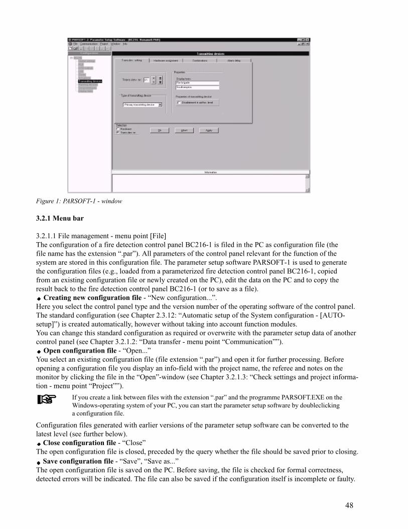
48
Figure 1: PARSOFT-1 - window
3.2.1 Menu bar
3.2.1.1 File management - menu point [File]The configuration of a fire detection control panel BC216-1 is filed in the PC as configuration file (thefile name has the extension “.par”). All parameters of the control panel relevant for the function of thesystem are stored in this configuration file. The parameter setup software PARSOFT-1 is used to generatethe configuration files (e.g., loaded from a parameterized fire detection control panel BC216-1, copiedfrom an existing configuration file or newly created on the PC), edit the data on the PC and to copy theresult back to the fire detection control panel BC216-1 (or to save as a file).
Creating new configuration file - “New configuration...”.Here you select the control panel type and the version number of the operating software of the control panel.The standard configuration (see Chapter 2.3.12: “Automatic setup of the System configuration - [AUTO-setup]”) is created automatically, however without taking into account function modules.You can change this standard configuration as required or overwrite with the parameter setup data of anothercontrol panel (see Chapter 3.2.1.2: “Data transfer - menu point “Communication””).
Open configuration file - “Open...”You select an existing configuration file (file extension “.par”) and open it for further processing. Beforeopening a configuration file you display an info-field with the project name, the referee and notes on themonitor by clicking the file in the “Open”-window (see Chapter 3.2.1.3: “Check settings and project informa-tion - menu point “Project””).
If you create a link between files with the extension “.par” and the programme PARSOFT.EXE on theWindows-operating system of your PC, you can start the parameter setup software by doubleclickinga configuration file.
Configuration files generated with earlier versions of the parameter setup software can be converted to thelatest level (see further below).
Close configuration file - “Close”The open configuration file is closed, preceded by the query whether the file should be saved prior to closing.
Save configuration file - “Save”, “Save as...”The open configuration file is saved on the PC. Before saving, the file is checked for formal correctness,detected errors will be indicated. The file can also be saved if the configuration itself is incomplete or faulty.
49
A faulty file cannot be copied to a control panel.
Convert - “Convert”The parameter file opened or downloaded from the control panel is adjusted to the latest software version ofthe fire detection control panel.
Before you load the converted data into the control panel, you have to update the software of the fire detectioncontrol panel to the latest edition. The hardware of the control panel must be compatible to the software,otherwise the control panel will not work correctly. Contact the deliverer of the control panel in case of doubt!
The conversion is made as follows:- load the existing (old) configuration into the PC and subsequently convert it,- update the software of the control panel (see also Chapter 4.1.6: “Loading a new software version PL149"),- load the converted configuration back in the control panel.
Reconverting into the old data format is not possible. If necessary, create a safety copy of the old settingson the PC before starting conversion.If the file was created for the latest software version or was already converted to the latest edition, this menupoint is greyed.
Print - “Print...”The open configuration file is printed out on the optional printer, selected in the menu point “Printer setup...”.
Printer setup - “Printer setup...”A printer is selected and set up with the usual Windows methods.
Print in file - “Print in file ...”The opened configuration file is saved on the PC as ASCII-file. The file name is selected by means ofcommon Windows methods. Subsequently the file can be opened for viewing with a suitable ASCII editor orby confirming the dialogue box “Shall the file be opened?”.
Exit - “Exit”You exit the parameter setup programme PARSOFT-1. If necessary it is queried if the file should be saved.
3.2.1.2 Data transfer - menu point “Communication”The setup data is transferred from and to the fire detection control panel by way of a serial interface. Thebaud rate is fixed to 38400 baud (with software versions older than V4.06 a baud rate of 57600 baud isused, which PARSOFT-1 automatically recognizes and considers).
With the start of PARSOFT-1 the first connection establishment is executed. If this connection establishmentwas unsuccessful it is renewedly tried to open the COM interface and to establish connection priorto reading or writing the configuration (see Chapter 3.1: “Installation of the parameter setup softwarePARSOFT-1").
Due to reasons of safety the installer code is queried before transferring data from and to the control panel.The input of the manufacturer code of the day instead of the installer code is also possible if usingPARSOFT-1/version V1.06 or newer (see Chapter 4.2.1: “Lost installer code”). If you have lost the installercode and you are using an older PARSOFT version you have to enter a new installer code on the control panelby using the code number of the day before you can execute the data transfer with PARSOFT-1.
Updating the software of the control panel - “Software update...”A new version of the central processing board software PL149 can be installed in the control panel via thismenu point. Notice that the whole existing setup of the control panel thereby can be deleted and reset toinitial values (if this is the case, a dialogue box will indicate that). If necessary, load the setup on your PCbefore transmitting the new software to the control panel, see also in Chapter 4.1.6: “Loading a new softwareversion PL149”.
50
Loading configuration back into the control panel - “PC BC216 “A created configuration is loaded back in the control panel by clicking this menu point. It is automaticallychecked if the configuration just generated is compatible with the software version of the control panel and ifit is formally correct. Possible faults will be shown by means of the dialogue box and can be partly correctedimmediately.If the parameter setup of the control panel was changed, the fire detection control panel BC216-1 will restartafter conclusion of the loading process.
Reading configuration from the control panel - “BC216 PC “The entire control panel configuration is read out and can be saved on the hard disk of the PC. The parametersetup software checks before if the software version of the control panel is compatible to the selected systemconfiguration.
You cannot perform an AUTO-setup of the control panel by using PARSOFT-1. If you wish to base thework with PARSOFT-1 on the parameters of an auto-setup control panel, you will have to perform theAUTO-setup first on the control panel itself (see Chapter 2.3.12: “Automatic setup of the Systemconfiguration - [AUTO-setup]”) and subsequently transfer the resulting configuration from the controlpanel to the PC.
With the exception of the summer/wintertime data, the system settings (see User Manual SeriesBC216 / Part A) cannot be set via PARSOFT-1.
Reading out the event memory of the control panel - “Event memory PC”The entire contents of the event memory of the control panel is read out and can be saved in an ASCII filewith fixed column division without separating characters on the PC. The data can be read with ASCII-textprogrammes, (e.g., Notepad) or transferred to standard programmes (e.g., dBase, etc.,) and further processed.
Resetting the event counter - “Special functions - resetting event counter”The event counter (alarm counter) is reset to 0. This menu point is furnished in order to reset a controlpanel, which has been subject to extensive test alarms (e.g., on the occasion of staff training by the installer)prior to the delivery to the customer.This menu point is only accessible for especially authorized companies.
Deleting the event memory - “Special functions - delete event memory”The content of the event memory is deleted. This process cannot be undone!This menu point is only accessible for especially authorized companies.
Setting COM interface number - “Settings...”Here you set the number of the COM interface of the PC.
This setting must be made before you start with the data transfers between PC and fire detection controlpanel!
3.2.1.3 Check settings and project information - menu point “Project”You can check the created setup data on formal errors and enter project specific information in this menu.
Check setup and create error file - “Check setup”The control panel setup is checked on formal errors. Eventually existing errors are entered in a file(file name: <Parameter file name>.err); successively, the file is opened for viewing.
Check setup and correct interactively - “Interactive error correction”The control panel setup is checked on formal errors. Eventually existing errors are entered in a file(file name: <Parameter file name>.err). A dialogue box providing instant correction possibility is opened insome cases. Successively, the file is opened for viewing.
Project information - “Data...”In this menu point you enter the project name (50 characters), the referee (50 characters) and informalnotes (200 characters). This information supports you when selecting a parameter file in the “Open”-window.
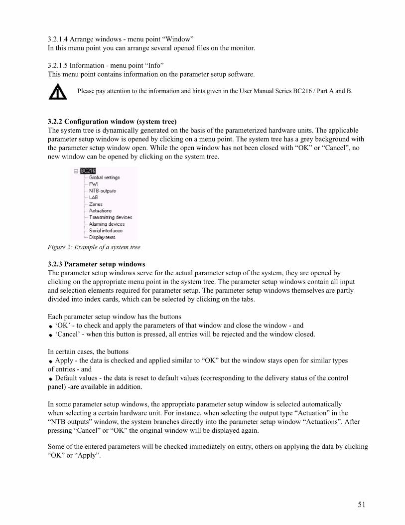
51
3.2.1.4 Arrange windows - menu point “Window”In this menu point you can arrange several opened files on the monitor.
3.2.1.5 Information - menu point “Info”This menu point contains information on the parameter setup software.
Please pay attention to the information and hints given in the User Manual Series BC216 / Part A and B.
3.2.2 Configuration window (system tree)The system tree is dynamically generated on the basis of the parameterized hardware units. The applicableparameter setup window is opened by clicking on a menu point. The system tree has a grey background withthe parameter setup window open. While the open window has not been closed with “OK” or “Cancel”, nonew window can be opened by clicking on the system tree.
Figure 2: Example of a system tree
3.2.3 Parameter setup windowsThe parameter setup windows serve for the actual parameter setup of the system, they are opened byclicking on the appropriate menu point in the system tree. The parameter setup windows contain all inputand selection elements required for parameter setup. The parameter setup windows themselves are partlydivided into index cards, which can be selected by clicking on the tabs.
Each parameter setup window has the buttons ‘OK’ - to check and apply the parameters of that window and close the window - and ‘Cancel’ - when this button is pressed, all entries will be rejected and the window closed.
In certain cases, the buttons Apply - the data is checked and applied similar to “OK” but the window stays open for similar types
of entries - and Default values - the data is reset to default values (corresponding to the delivery status of the control
panel) -are available in addition.
In some parameter setup windows, the appropriate parameter setup window is selected automaticallywhen selecting a certain hardware unit. For instance, when selecting the output type “Actuation” in the“NTB outputs” window, the system branches directly into the parameter setup window “Actuations”. Afterpressing “Cancel” or “OK” the original window will be displayed again.
Some of the entered parameters will be checked immediately on entry, others on applying the data by clicking“OK” or “Apply”.
52
An overview window containing all setable units (zones, actuations, etc.) can be opened with some selectionfields (selection of a logic number of a zone, actuation, transmitting device, alarming device or of a zoneelement) by clicking the field with the right mouse button. The belonging number is directly entered in theselection field by clicking the desired entry.
A selection of the NTB outputs, FWI oc-outputs and FWI inputs is possible similarly in the correspondingwindow by clicking the field “Hardware assignment”, which surrounds the selection field, with the rightmouse button.
The permissible parameters are thoroughly described in Chapter 2: “Parameter setup by means of controlpanel keypad” and in the sub-chapters included in that chapter, please note the information and warning hintsmentioned in these chapters when setting the parameters.
3.2.4 Information windowInformation texts on the chosen system part or concerning the momentarily selected entry are shown in theinformation window.
3.3 Typical parameter setup process with PARSOFT-1 Connect your PC with the serial interface module SIM216-1 of the control panel.
You can also set the parameters of a SIM216-1 used in the control panel for connecting a printer for thispurpose - do not forget to change the parameters of the serial interface back for the printer after completingthe job.
Start PARSOFT-1 on the PC (Programmes - Parsoft - PARSOFT-1)Create either a new configuration file (“File - New configuration...”) or open an already existing configura-
tion file (“File - Open”). Set the COM interface of the PC to the required value (“Communication - Settings...”). In both the above cases you can now - if required - transfer the existing configuration of the control panel to
your PC (“Communication - BC216 . PC”). Notice that setup data currently on the PC are thereby overwrittenby data of the control panel.
Edit the configuration files to suit the requirements and, subsequently, save the data in a file (“File - Save” or “File - Save as...”). Copy the setup data from the PC to the control panel (“Communication - PC . BC216”). Disconnect the connection between PC and SIM216-1, remove the SIM216-1 again from the control panel
if applicable. Set the parameters of the interface from PARSOFT-1 to the initial setting or to “Not defined”. Carefully check all functions of the fire detection control panel. Do not limit this check to the parameters
just modified - you may have also influenced other functions mistakenly!

53
4 Maintenance, reconditioningThis chapter includes only hints on maintenance and reconditioning for the fire detection control panelBC216-1, it does not provide any instructions for the expert maintenance or repair of an installed fire detec-tion system.
This chapter of the manual does not replace the training of a specialist installer by SHE or its authorizedrepresentative for proper planning, installation, commissioning, maintenance and repair for a fire detectionsystem established with the fire detection control panel BC216-1.
4.1 MaintenanceWith the exception of the stand-by batteries, no components with limited functioning period as a result ofwear are installed in the fire detection control panel. The maintenance of the fire detection control panelitself is therefore mainly limited to checks of external damage (e.g., the key pad), a check of the emergencypower supply and an extensive function check.
Reliably prevent that an undesirable activation of one of the transmitting devices or an actuation resultsthrough one of the function tests during the maintenance! Under certain conditions you may be liable for thedamages resulting from this!
Inform the user of the fire detection system that the fire detection system as a whole or in part is notoperational during the maintenance work!
4.1.1 Checking the final charge voltageWith the stand-by batteries charged and the mains voltage connected, the charge voltage of the stand-bybatteries must be between 26.0 and 29.0V depending on the temperature.
A voltage value below 26V with connected mains voltage is only permissible if the stand-by batteries arerecharged after having been discharged. In this case check if the charge current is flowing.
If the voltage of the stand-by batteries drops below 21V in operation during main power failure, the stand-bybatteries will be disconnected from the control panel to prevent total discharge. Once the mains voltagereturns, the stand-by battery charging is started automatically. However, if the voltage of the stand-by batterydrops below approximately 16V (e.g., with a defective battery), charging is no longer started automatically.
Check to see if the charge voltage of the two series-connected 12V-stand-by batteries is identical.
4.1.2 Checking the stand-by batteriesThe useful life of the stand-by batteries employed is specified by the battery manufacturer. The usual stand-bybatteries have an useful life of approximately 4 years, but stand-by batteries with considerably longer periodof usage are available on the market (up to 10 years according to manufacturer’s specifications).
Ensure that the replaced stand-by batteries are properly disposed of. The batteries are based on a lead andsulphuric acid basis, such a battery must not enter the domestic waste under any circumstances!
Clearly mark the newly installed stand-by batteries with an expiry date, corresponding to the useful lifespecified by the manufacturer, taking into account a certain safety factor.
An exact check of the stand-by batteries requires much time and is only possible in cooperation with therespective manufacturing company. A rough estimate of the battery condition, however, is possible through abrief load test with high load (e.g., with a load that would result in total discharge in 5...10 hours). To do so itis essential to disconnect the stand-by batteries from the control panel! Disconnect the series-connectedbatteries and test each battery separately.

54
The clock installed in the control panel has a running reserve of a few minutes. If you have completelyde-energised the control panel, the clock must be reset once the power has been switched on again.
The single batteries must be of the same type; under no circumstances may 12V batteries with differentcapacities be connected in series.
The expected usable life and the age of the series connected 12V batteries ought to be identical.Equal charging of the batteries is to be expected then only. Therefore it is highly recommended to changeboth batteries at a time if one 12V battery has to be changed due to a defect.
4.1.3 Earth leakage monitoringThe fire detection control panel BC216-1 continuously monitors the cabling of the entire fire detection systemfor earth leakage. However, if this check has been switched off during commissioning because system partsmust be continuously connected to the earth potential for company reasons (e.g., with intrinsically safecircuits), an additionally faulty earth leakage cannot be detected automatically by the control panel.
As part of the maintenance in such cases, you should disconnect the circuits connected with the earth poten-tial from the control panel and temporarily re-enable the earth leakage monitoring function on the controlpanel (see Chapter 2.3.1: “Parameter setup of the global settings of the control panel - [Global settings]”). Inthis way you check if the remaining cabling of the fire detection system is free of earth leakages. Subse-quently set the parameters to remove the earth leakage monitoring once again and reconnect the disconnectedcircuits to the control panel.
You may never separate the connection of intrinsically safe circuits with the earth potential(e.g., the equipotential busbar)! Sparks may be generated thereby whose energy is sufficient forignition and, in succession, for starting an explosion in the intrinsically safe area!
4.1.4 Function checkDuring control panel maintenance, carry out a function check
of the displaying installations (light-emitting diodes, LC-display, buzzer) with the function “Display test”, of all keypad buttons, of all inputs (detector zones, fire brigade interface, etc.), of all outputs (fire brigade interface, auxiliary outputs of the NTB216-1, actuations, transmitting devices,
alarming devices, etc.)
You must prevent undesired activations of extinguishing systems or other actuations, unannouncedactivations of transmitting devices or unannounced activations of alarming devices to occur bycarrying out the function checks! Before starting the function checks, contact the person responsiblefor the fire alarm system (e.g., fire prevention officer, safety officer, etc.) in order for him to make therequired mechanical or electrical switch-offs and to inform the concerned persons of the test alarmon time. Before the test activation of a transmitting device you have to inform the concerneddesignated alarm respondents (e.g., the fire brigade) about the imminent activation.
of the devices connected to the INFO bus (fire brigade control unit, etc.) and of other peripheral devices (e.g., printer).
4.1.5 Maintenance support for loop elementsIntelligent loop technique allows to make exact statements on the condition of the ADM- andADMPROelements (detectors and modules) applied on the loop. This information on the condition providesthe basis for a selective and efficient maintenance of the elements. Following information is available on theLC-display or on a connected printer for the maintenance technician:
the parameterized detector or module type (only on the printer) the current measured value the 6 month long-term drift (only on the printer)

55
the alarm threshold adjusted corresponding to the long-term drift (only on the printer) the measured value which the detector or the module presumably will be having in 12 month´s time at
constant ambient conditions (only on the printer) a maintenance recommendation on how many months the detector will presumably be fully operational
without maintenance.
The measured values of the detectors and modules, the upper and lower fault threshold and the alarmthreshold are dependent on the detector brand and the detector type. The values of the most important detec-tors supported by the control panel are listed in below table.
4.1.5.1 Maintenance support on the LC-displayBy calling up the menu point [Zone:] and successively entering the zone number, the element number andselecting the function “Measured val./Maint.”, the current measured value and the maintenance recommenda-tion are displayed on the LC-display for the selected detector. For further information see User Manual SeriesBC216 / Part A, “Operating single elements of detector zones”.
4.1.5.2 Maintenance support on the printerBy calling up the menu point [System] - [Print-out] - [Meas. print-out zone] and entering the desired area,printer filter and the repeat interval you start the print-out of the measured values of the intelligent detectorsconnected to the Loop interfaces LIF64-1 (see User Manual Series BC216 / Part A, description of the menupoint [System]).
You find information on printer settings in Chapter 2.3.11: “Parameter setup of the interfaces- [Interfaces]”.
********************************************************************************02.03.2001 14:21 Measurement zone 0001/013 - 0001/015Filter: Print all********************************************************************************Zone/el. TYPE 09.00 10.00 11.00 12.00 01.01 02.01 ACT. A-VAL 03.02 MAINT0001/013 O-S 65 66 65 67 67 68 69 200 75 >>120001/014 O-S 94 103 102 104 108 109 114 205 123 <00>
Element dirty0001/015 O-S 77 81 83 88 92 96 102 202 118 >=04
Figure 3 Printing example of a detector measured value print-outFollowing information is printed for every detector (from left to right):- the detector type (see following table)- the past 6 month´s mean values,- the actual measured value,- the alarm threshold value of the detector, valid at the time of printing,- the expected measured value in one year´s time and- the maintenance calculation, i.e., for how many months the detector will presumably be working in normal range(<00> means: replace immediately)
Detector condition Apollo System SensorDetector defective, removed or short circuit in the loop line 0 0Detector defective 1 – 7 1 – 32Detector in normal range 8 – 45 33 – 112Dirtiness threshold 45 112Alarm threshold of a new detector 55 I – detector: 150
O – detector: 200T – detector: 166

56
Table 5: Explanation of the type abbreviations used in the measured value print-outThe abbreviation of the detector manufacturer (A = Apollo, S = System Sensor) is appended in theprint-out.
The measured values of control modules (which are used for actuations and alarming devices) of a loop canbe put out in the same way (menu points [Meas. print-out act.] and [Meas. print-out al.d]). The maintenancecalculation is insignificant with these elements (as with monitor modules and manual call points), the mea-sured value of these elements should be constant for its entire life time.
4.1.5.3 Replacement of an ADM- or ADMPRO-detectorThe individual measured values of the past 6 months and the thereby calculated alarm threshold are savedin the control panel for every installed ADM- and ADMPRO-detector. If you replace a faulty or dirty detectorwith a new detector, the mean values and the alarm threshold are adjusted to the new condition relatively fast(i.e., within a few weeks).
Principally refrain from exchanging installed detectors in a system. Every detector is identified by thecontrol panel by its set physical address; measured values are assigned and saved to this address.If you exchange the physical addresses of two detectors and re-insert them in the base, the control panelcontinues to work with these detectors with the historical data of the other detector, respectively!Therefore it is possible for the next maintenance recommendation to provide values of only limited sense.
When replacing a defective or dirty detector with a new detector, it is indispensable to set the same physicaladdress on the new detector which was set on the replaced detector!
4.1.6 Loading a new software version PL149The control panel software PL149 is constantly further developed and adjusted to the progress of the firedetection technology and to changed requirements due to modifications of standards and regulations. Upgrad-ing the fire detection control panel BC216-1 to a new software version is effected by loading the new soft-ware from a PC by means of PARSOFT-1.
Type abbreviation Detector and module typeMCP Manual call pointCM Conventional detector moduleI Ionisation detectorLA1 Laser detector level 1LA5 Laser detector level 5LA9 Laser detector level 9BEA Beam detectorMD Multisensor discoveryO Optical detectorOT Optical-thermal detectorCMN Control module with relay contactCMS Control module with supervisionCM Control moduleCMN Control module withoput supervisionDT Rate-of-rise temperature detectorMT Maximum temperature detectorMM Monitor moduleMCP Monitor module manual call pointMMM Monitor module miniMMS Monitor module for special detectors
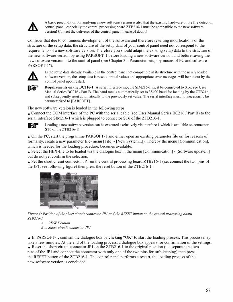
57
A basic precondition for applying a new software version is also that the existing hardware of the fire detectioncontrol panel, especially the central processing board ZTB216-1 must be compatible to the new softwareversion! Contact the deliverer of the control panel in case of doubt!
Consider that due to continuous development of the software and therefore resulting modifications of thestructure of the setup data, the structure of the setup data of your control panel need not correspond to therequirements of a new software version. Therefore you should adapt the existing setup data to the structure ofthe new software version by using PARSOFT-1 before loading a new software version and before saving thenew software version into the control panel (see Chapter 3: “Parameter setup by means of PC and softwarePARSOFT-1").
Is the setup data already available in the control panel not compatible in its structure with the newly loadedsoftware version, the setup data is reset to initial values and appropriate error messages will be put out by thecontrol panel upon restart.
Requirements on the BC216-1: A serial interface module SIM216-1 must be connected to ST6, see UserManual Series BC216 / Part B. The baud rate is automatically set to 38400 baud for loading by the ZTB216-1and subsequently reset automatically to the previously set value. The serial interface must not necessarily beparameterized to [PARSOFT].
The new software version is loaded in the following steps: Connect the COM interface of the PC with the serial cable (see User Manual Series BC216 / Part B) to the
serial interface SIM216-1 which is plugged to connector ST6 of the ZTB216-1.
Loading a new software version can be executed exclusively via interface 1 which is available on connectorST6 of the ZTB216-1!
On the PC, start the programme PARSOFT-1 and either open an existing parameter file or, for reasons offormality, create a new parameter file (menu [File] - [New System...]). Thereby the menu [Communication],which is needed for the loading procedure, becomes available.
Select the HEX-file to be loaded via the dialogue box in the menu [Communication] - [Software update...]but do not yet confirm the selection.
Set the short circuit connector JP1 on the central processing board ZTB216-1 (i.e. connect the two pins ofthe JP1, see following figure) then press the reset button of the ZTB216-1.
Figure 4: Position of the short circuit connector JP1 and the RESET button on the central processing boardZTB216-1
A ... RESET buttonB ... Short-circuit connector JP1
In PARSOFT-1, confirm the dialogue box by clicking “OK” to start the loading process. This process maytake a few minutes. At the end of the loading process, a dialogue box appears for confirmation of the settings.
Reset the short circuit connector JP1 on the ZTB216-1 to the original position (i.e. separate the twopins of the JP1 and connect the connector with only one of the two pins for safe-keeping) then pressthe RESET button of the ZTB216-1. The control panel performs a restart, the loading process of thenew software version is concluded.
58
During the processes described above the fire detection control panel BC216-1 is in an operating conditionsimilar to that during system fault (see User Manual Series BC216 / Part A), i.e. alarm messages can bereceived by the function modules and passed on to the primary alarming device and the primary transmittingdevice. In order to avoid undesired alarms it is indispensable to shut down the connected detector zoneswhile loading a new software version (e.g., by disconnecting the corresponding function modules).
The internal clock of the control panel is stopped during the loading procedure. Therefore you must set thetime newly after completing the loading procedure.
4.2 ReconditioningA multitude of checks is continuously performed internally by the fire detection control panel BC216-1 andreported on the LC-display by using text and acoustically by using the internal buzzer. Detailed additionalinformation on any fault occurred can be called up for each fault by means of the ‘INFO’-button.This information is generally sufficient for the trained specialist installer to rapidly correct the fault.
“Fault” means a fault in the installed fire detection system, but not the activation of a fault detector.
4.2.1 Lost installer codeIt is not possible to read out an installer code from the control panel. Once the installer code saved in thecontrol panel has been lost, access to authorisation level 3 can only be gained with the help of the manufac-turer of the control panel or his national representative.
For this you have to press the -button in the menu point [Authorization code:] (i.e. in authorisationlevel 1). The following appears on the LC-display for 5 seconds:
in the first line the date and the time, in the second line the word “Key number:” and in the third line a 5-digit random figure, the key number.
The indicated date and key number must be given to the manufacturer or his representative who will deter-mine a code number of the day from these two pieces of information. You then enter this code number of theday as installer code, by this automatically delete the forgotten installer code and, as first additional step, youhave to establish a new installer code (see User Manual Series BC216 / Part A).
The code number of the day is only valid as entry code of this control panel on the day displayed on thecontrol panel LC-display when reading out the key number.


![Homicide by Necessity - Chapman University...2006] Homicide by Necessity 121 On the other hand, from a philosophical standpoint, the in-tentional killing of innocents, as in the Trolley](https://img.pdfslide.us/doc/110x75/5edf7441ad6a402d666accef/homicide-by-necessity-chapman-2006-homicide-by-necessity-121-on-the-other.jpg)