Embed Size (px)
Citation preview

EWP FDIG CANADA March 2014
FIRE DESIGN & INSTALLATION
GUIDE
The information in this document pertains to use in CANADA ONLY, Limit States Design. Refer to the Fire Design and Installation, US Version for use in the United States.
LIMIT STATES DESIGN CANADA

2
Boise Cascade EWP • Fire Design and Installation Guide • CANADA • March 2014 LIMIT STATES DESIGN CANADA
2Boise Cascade EWP Product Profiles
Product Profiles . . . . . . . . . . . . . . . . . . . . . . . . . . . . . . . . . . . . . . . 2Introduction, Construction and Fire Safety . . . . . . . . . . . . . . . . . . .3Fire Resistance Ratings . . . . . . . . . . . . . . . . . . . . . . . . . . . . . . . . 445 Minute Resistance Rated Floor and Roof Assemblies . . . . . . . . .5One Hour Fire Resistance Rated Floor and Roof Assemblies . 6 - 11
Two Layers ⅝" Type X Gypsum Wallboard - BCI® and AJS®Joists . . . . . . . . . . . . . . . . . . . . . . . . . . . . . . . . . . . . . 6Two Layers ½" Type C Gypsum Wallboard - BCI® and AJS® Joists . . . . . . . . . . . . . . . . . . . . . . . . . . . . . . . . . . . . 7One Layer ⅝" Type C Gypsum Wallboard - BCI® 60/90 and AJS® Joists . . . . . . . . . . . . . . . . . . . . . . . . . . . . . . . 8One Layer ½" Type C Gypsum Wallboard - BCI® 60/90 and AJS®Joists . . . . . . . . . . . . . . . . . . . . . . . . . . . . . . . . 9One Layer ⅝" Type C Gypsum Wallboard - BCI® 90 Joists and AJS® 25/30 Joists . . . . . . . . . . . . . . . . . . . . . . . 10One Layer ⅝" Type C Gypsum Wallboard & Strips - BCI® 90 Joists and AJS® 25/30 Joists . . . . . . . . . . . . . . . . . . . . . . . 11
Two-Hour Fire Resistance Rated Floor and Roof Assemblies . . .13Three Layer ⅝" Type C Gypsum Wallboard - BCI® and AJS® Joists . . 13
One-Hour Fire Resistance Rated Rim Board Assemblies 13, 15, 16Two-Hour Fire Resistance Rated Rim Board Assemblies . . .14, 17Sprinkler Attachments . . . . . . . . . . . . . . . . . . . . . . . . . . . . . . . . .18Commercial Sprinkler Pipe Weights . . . . . . . . . . . . . . . . . . . . . 18Sprinkler Attachment Details FS01-FS21 . . . . . . . . . . . . . . 18 - 21Residential Sprinkler Details . . . . . . . . . . . . . . . . . . . . . . . . . . . . 21BCI® Joist Hole Location & Sizing . . . . . . . . . . . . . . . . . . . . . . . . 22AJS® Joist Hole Location & Sizing . . . . . . . . . . . . . . . . . . . . 23-24Frequently Asked Questions Regarding Fire Suppression . . . . . .25Lifetime Guarantee . . . . . . . . . . . . . . . . . . . . . . . . . . Back Cover
Tabl
e of
Con
tent
s
BCI® Joists and VERSA-LAM® Beams —Eastern (Lena, LA)
ALLJOIST® (St . Jacques, NB)
BOISE GLULAM® (Homedale, ID)
BCI® Joists: CCMC 13300 VERSA-LAM®: CCMC 12472
BCI® Joists: CCMC 13300 VERSA-LAM®: CCMC 12472
AJS® Joists: CCMC 12787
BOISE GLULAM® Beams are compliant with CSA O122, CSA O177
BCI® Joists and VERSA-LAM® Beams —Western (White City, OR)
Header (Framing) BeamsArchitectural Appearance Beams Columns
Boise Cascade EWP • Fire Design and Installation Guide • CANADA • March 2014
3
LIMIT STATES DESIGN CANADA
3Introduction
Construction and Fire Safety
Boise Cascade manufactures and distributes quality Engineered Wood Products for modern construction throughout the United States and Canada. These products include BCI® & AJS® wood I-joists, VERSA-LAM® beams/columns/studs, BOISE GLULAM® beams/columns, and BOISE RIMBOARD® products. When compared to sawn lumber, Boise Cascade Engineered Wood Products provide higher strength, stiffness and dimensional consistency through more efficient use of raw materials to exacting industry quality standards required for modern construction.
This guide provides detailed information for the design and construction professional about the relationship between Boise Cascade Engineered Wood Products, national building codes, andactual fire events. For further information, contact Boise Cascade EWP Engineering at (800) 964-6999 or your local Boise Cascade representative.
The National Building Code of Canada (NBCC) is divided into three divi-sions; Division B – Acceptable Solutions; Division A – Compliance, Objec-tives and Functional Statements; and Division C – Administrative Provisions. Within Division B, Part 3 provides fire protection solutions for all buildings, with some exceptions of smaller structures such as housing. Part 3 of the NBC applies to buildings exceeding 6 460 square feet in building area or exceeding 3 storeys in building height used for major occupancies classi-fied as: Group C - Residential, Group D – Business and Personal Services, Group E – Mercantile, and Group F – Low Hazard Industrial.
Heavy Timber Construction is defined in section 3.1.4.7. Heavy Timber is allowed in combustible construction if the fire-resistance rating does not exceed 45 minutes. Because of wood’s ability to maintain structural capacity during a fire, Heavy Timber allows large, open areas with exposed beams and columns. For minimum cross-sectional areas required for framing members in Heavy Timber Construction; please see the table below for minimum BOISE GLULAM® and VERSA-LAM® sizes. A calculation method for beams and columns requiring fire-resistance ratings greater than 45 minutes is found in Appendix D-2.11.1 of Division B. Please contact Boise Cascade EWP Engineering for further information.
Supported Assembly Structural Element Minimum Sizes [in x in]Roof Only Columns 5.125 x 7.5Roof Only Beams, Girders 3.125 x 6
Floor or Floor + Roof Columns 7 x 7.5Floor or Floor + Roof Beams, Girders 5.125 x 9 or 7 x 7.5
Fire resistive ratings are defined in section 3.1.7 of Division B. The rating of a material, assembly of materials, or a structural member shall be determined by testing per CAN/ULC-S101 or assigned a rating per Appendix D of the NBCC.
Part 9 of Division B provides solutions for housing and smaller buildings, as defined by subsection 1.3.3.3 of Division A. Specifically, Part 9 applies to buildings of three storeys or less, having an area no greater than 6,460 square feet, and having the classification of Group C, D, E, or F (divisions 2 and 3). Section 9.10 defines fire protection for these types of structures.
4
Boise Cascade EWP • Fire Design and Installation Guide • CANADA • March 2014 LIMIT STATES DESIGN CANADA
Fire Resistance Ratings
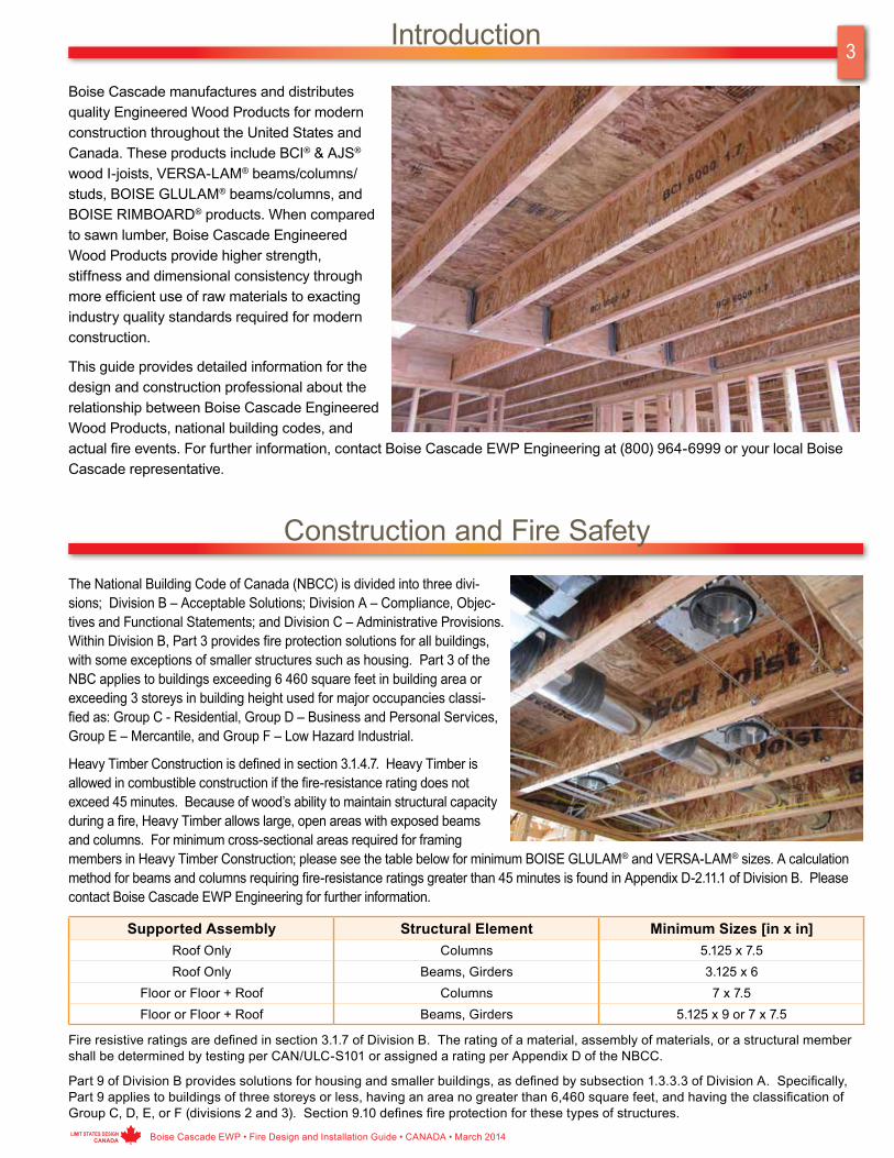
Fire Resistance RatingsFire resistance is the ability of materials or assemblies to prevent or restrict the passage of excessive heat, hot gases, or flames while continuing to support the structural loads. The performance of wall and floor assemblies exposed to fire is determined through testing in accordance with ASTM E 119 or NFPA 251 or CAN/ULC-S101. In a full-scale assembly test (at least 180 ft2 for a floor assembly and 100 ft2 for a wall assembly), a specimen is loaded to the maximum design load and directly exposed to flame. The rate of temperature rise is controlled to follow a standard time-temperature curve. Results of full-scale fire endurance assembly tests provide a repeatable, relative measure of fire resistance based on three failure crite-ria: structural collapse, flame penetration, or excessive temperature rise on the unexposed surface of the assembly. National building codes require that certain types of buildings or occu-pancy classes be constructed with floor and wall assemblies that provide fire endurance for a specified period of time based on these tests. When required by national building codes, fire endurance rated assemblies are available for BCI®, AJS® and VERSA-LAM® products. The fire endurance assemblies in this guide
can be further referenced in the National Building Code Canada and/or assembly listings with APA – The Engineered Wood Association (APA Product Report PR-S201), the accredited testing and product certification agency for Boise Cascade EWP fire resistant assembly details. Per the section titled Certification, located on page xiv of NBCC 2010 Volume 1, accredited certification bodies are found on the Standards Council of Canada (SCC) web site, www.scc.ca. APA – The Engineered Wood Association is listed in the SCC directory; the following is the direct link: http://www.scc.ca/en/accreditation/product-process-and-service-certification/directory-of-accredited-clients. All fire resistant assemblies shown in this guide are found within the APA – The Engineered Association Product Report PR-S201: www.apawood.org/level_b.cfm?content=prd_rept_main.
Boise Cascade EWP • Fire Design and Installation Guide • CANADA • March 2014
5
LIMIT STATES DESIGN CANADA
BASE ASSEMBLYComponent Material Specification
Floor Topping (Optional) VariesReference sound ratings if applicable
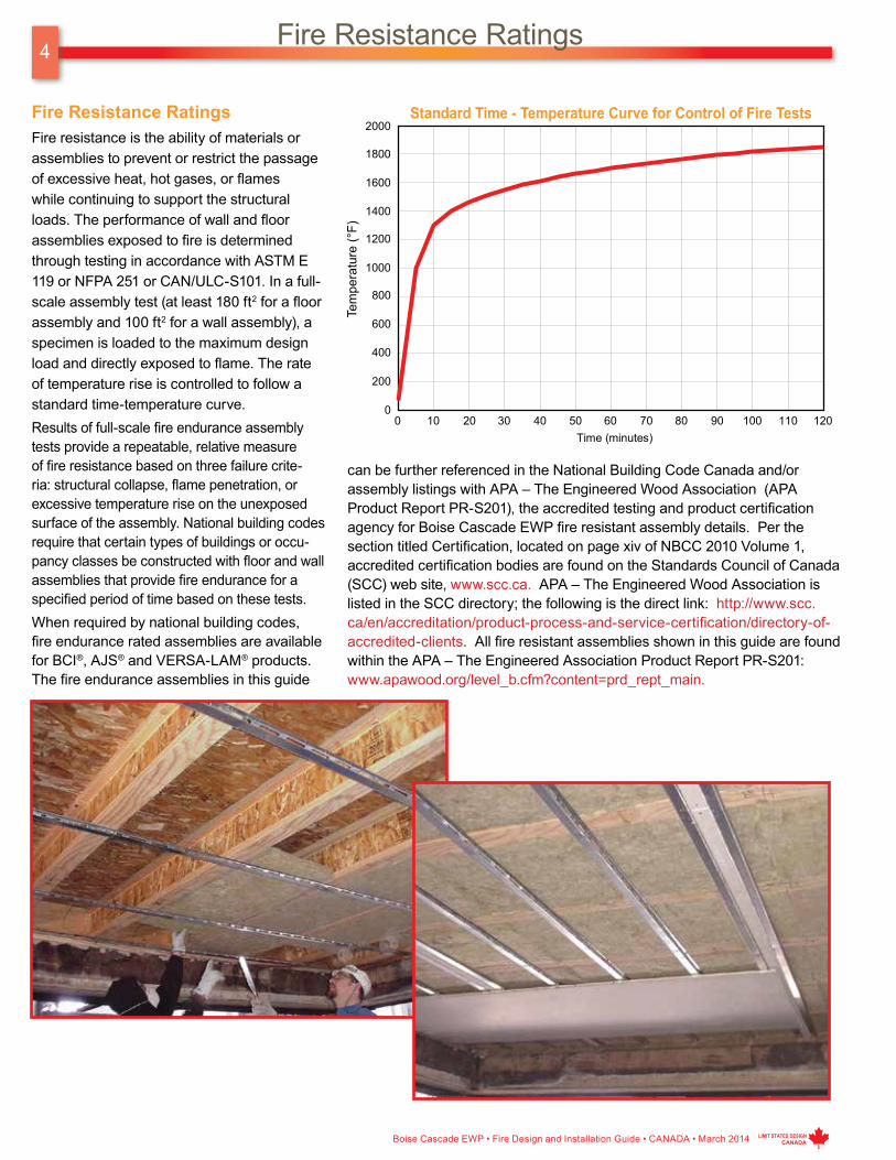
Floor Sheathing Min. 23/32 inch (18 mm) Wood Structural PanelA modified contact construction adhesive must be applied to the top of the joists prior to placing sheathing. The sheets shall be installed with their long edge perpendicular to the joists with end joists centered over the top flange of joists and staggered one joist spacing with adjacent sheets. Floor sheathing must be installed per code requirements..
Insulation Min. 3½ inch (89 mm) Glass Fiber Insulation or 2 inch (51 mm) Rock Wool Insulation, 2.5 pcf Nominal.
Reference sound ratings if applicable.
Structural Members Min. 9½ inch (241mm) Deep JoistsMaximum 24 inch (610 mm) on center spacing. Minimum BCI® flange dimensions of 1⅛ inch (29mm) thick by 1½ inch (38mm) wide.
Minimum AJS® flange dimensions of 1½ inch (38mm) thick by 2½ inch (64mm) wide.
Resilient Channels Min. 0.019 inch (0.5mm) Galvanized Resilient ChannelAttached perpendicular to the bottom flange of the joist with 1⅛ inch (29mm) Type W drywall screws. Channels are spaced a maximum of 16 inches (406mm) on center. Additional channels required at gypsum wallboard end joints such that each board rests on its own channel. These additional channels shall extend to the next joist on each side of the board edges.
Ceiling (1) Layer of ⅝ inch (16mm) Type C Gypsum WallboardInstalled with long dimension perpendicular to resilient channels and fastened with minimum 1⅛ inch (29mm) Type S drywall screws at 7 inches (178 mm) on center. The end joints of the wallboard must be staggered the equivalent of two joist spacings with those of adjacent sheets. Screws shall be minimum 1½ inch (38mm) from board edge and ¾ inch (19mm) from board ends.Finish: The face layer joints must be covered with tape and coated with joint compound. Screw heads must also be covered with joint compound.
REFERENCEBCI® Joists AJS® Joists
2010 NBCC Table A-9.10.3.1.B., Assembly Num. F8, F10, F14, and F20
Similar to 2010 NBCC Table A-9.10.3.1.B., Assembly Num. F8, F10, F14, and F20
APA PR-S201 FR1 APA PR-S201 FR1
45-Minute Fire Resistance Rated Floor and Roof Assembly
One Layer ⅝" Type C Gypsum Wallboard - BCI® and AJS®Joists

6
Boise Cascade EWP • Fire Design and Installation Guide • CANADA • March 2014 LIMIT STATES DESIGN CANADA
One-Hour Fire Resistance Rated Floor and Roof Assemblies
BASE ASSEMBLYComponent Material Specification
Floor Topping (Optional) VariesReference sound ratings if applicable
Floor Sheathing Min. 23/32 inch (18 mm) Wood Structural PanelA modified contact construction adhesive must be applied to the top of the joists prior to placing sheathing. The sheets shall be installed with their long edge perpendicular to the joists with end joists centered over the top flange of joists and staggered one joist spacing with adjacent sheets. Floor sheathing must be installed per code requirements.
Insulation (Optional) Max 9½ inch (241 mm) Glass Fiber InsulationReference sound ratings if applicable
Structural Members Min. 9½ inch (241mm) Deep JoistsMaximum 24 inch (610 mm) on center spacing. Minimum flange dimensions of 1⅛ inch (29mm) thick by 1½ inch (38mm) wide.
Resilient Channels (Optional) Min. 0.019 inch (0.5mm) Galvanized Resilient ChannelAttached perpendicular to the bottom flange of the joist with 1¼ inch (32mm) Type S drywall screws. Channels are spaced a maximum of 16 inches (406mm), 24 inches (610mm) on center when I-joists are spaced a maximum of 16 inches on center.
Ceiling (2) Layers of ⅝ inch (16mm) Type X Gypsum WallboardBase Layer: Install with long dimension perpendicular to joist length. Attached to the bottom flange of the joists using 1¼ inch (32mm) Type W drywall screws at 24 inches (610 mm) on center. The end joints of the wallboard must be centered on the bottom flange of the joist and must be staggered the equivalent of two joist spacings with those of adjacent sheets.Face Layer: Install with long dimension perpendicular to joist length. Attached to the bottom flange of the joists through the first layer using 1⅞ inch (48mm) Type W drywall screws spaced at 12 inches (305mm) on center. The longitudinal joints of this layer must be offset 24 inches (610mm) from those of the base layer. The end joints must be centered on the bottom flange of the joists and offset a minimum of one joist spacing from those of the base layer. Additionally, face layer end joints are attached to the base layer with 1½ inch (38mm) Type G drywall screws at 12 inches (305mm) on center placed 2 inches (51mm) either side of the joint.With Resilient Channels: attached as described above except use 1⅜ inch (35mm) and 1¾ inch (44mm) Type S screws for the base and face layer, respectively. The end joints of the wallboard must be centered on a resilient channel and must be staggered the equivalent of two joist spacings with those of adjacent sheets.Finish: The face layer joints must be covered with tape and coated with joint compound. Screw heads must also be covered with joint compound
SOUND RATING (w/Resilient Channel)Components STC IIC
Base Assembly with Carpet and Padding 54 68Base Assembly with 3½" (89mm) Insulation 55 46Base Assembly with additional layer of ⅝" Sheathing and 9½" Insulation 61 50Base Assembly with Tarkett “Acoustiflor" vinyl and 3½" Insulation 59 50Base Assembly with cushioned vinyl, ¾" Gypsum Concrete and 3½" Insulation 67 51
REFERENCEBCI® Joists AJS® Joists
APA PR-S201 FR2 APA PR-S201 FR2Similar to 2010 NBCC Table A-9.10.3.1.B,
Assembly Num. F4, F9, F11, and F13, F15, F17, and F21.Similar to 2010 NBCC Table A-9.10.3.1.B,
Assembly Num. F4, F9, F11, and F13, F15, F17, and F21.
Two Layers ⅝" Type X Gypsum Wallboard - BCI® and AJS®Joists

Boise Cascade EWP • Fire Design and Installation Guide • CANADA • March 2014
7
LIMIT STATES DESIGN CANADA
BASE ASSEMBLYComponent Material Specification
Floor Topping (Optional) VariesReference sound ratings if applicable
Floor Sheathing Min. 23/32 inch (18 mm) Wood Structural PanelA modified contact construction adhesive must be applied to the top of the joists prior to placing sheathing. The sheets shall be installed with their long edge perpendicular to the joists with end joists centered over the top flange of joists and staggered one joist spacing with adjacent sheets. Floor sheathing must be installed per code requirements..
Insulation (Optional) Max 9½ inch (241 mm) Glass Fiber InsulationReference sound ratings if applicable
Structural Members Min. 9½ inch (241mm) Deep JoistsMaximum 24 inch (610 mm) on center spacing. Minimum flange dimensions of 1⅛ inch (29mm) thick by 1½ inch (38mm) wide.
Resilient Channels (Optional) Min. 0.019 inch (0.5mm) Galvanized Resilient ChannelAttached perpendicular to the bottom flange of the joist with 1¼ inch (32mm) Type S drywall screws. Channels are spaced a maximum of 16 inches (406mm), 24 inches (610mm) on center when I-joists are spaced a maximum of 16 inches on center.
Ceiling (2) Layers of ½ inch (13mm) Type C Gypsum WallboardBase Layer: Install with long dimension perpendicular to joist length. Attached to the bottom flange of the joists using 1¼ inch (32mm) Type W drywall screws at 12 inches (305 mm) on center. The end joints of the wallboard must be centered on the bottom flange of the joist and must be staggered the equivalent of two joist spacings with those of adjacent sheets.Face Layer: Install with long dimension perpendicular to joist length. Attached to the bottom flange of the joists through the first layer using 1⅝ inch (41mm) Type W drywall screws spaced at 12 inches (305mm) on center on intermediate joists and 6 inches (152mm) on center at end joints. The longitudinal joints of this layer must be offset 24 inches (610mm) from those of the base layer. The end joints must be centered on the bottom flange of the joists and offset a minimum of one joist spacing from those of the base layer. Additionally, face layer end joints are attached to the base layer with 1½ inch (38mm) Type G drywall screws at 8 inches (203mm) on center placed 6 inches (152mm) either side of the joint.With Resilient Channels: attached as described above except use 1¼ inch (32mm) and 1⅝ inch (41mm) Type S screws for the base and face layer, respectively. The end joints of the wallboard must be centered on a resilient channel and must be staggered the equivalent of two joist spacings with those of adjacent sheets.Finish: The face layer joints must be covered with tape and coated with joint compound. Screw heads must also be covered with joint compound.
SOUND RATING (w/Resilient Channel)Components STC IIC
Base Assembly with Carpet and Padding 54 68Base Assembly with 3½" (89mm) Insulation 55 46Base Assembly with additional layer of ⅝" Sheathing and 9½" Insulation 61 50Base Assembly with Tarkett “Acoustiflor” vinyl and 3½" Insulation 59 50Base Assembly with cushioned vinyl, ¾" Gypsum Concrete and 3½" Insulation 67 51
REFERENCEBCI® Joists AJS® Joists
APA PR-S201 FR3 APA PR-S201 FR3Similar to 2010 NBCC Table A-9.10.3.1.B,
Assembly Num. F4, F9, F11, and F13, F15, F17, and F21.Similar to 2010 NBCC Table A-9.10.3.1.B,
Assembly Num. F4, F9, F11, and F13, F15, F17, and F21.
Two Layers ½" Type C Gypsum Wallboard - BCI® and AJS® Joists
One-Hour Fire Resistance Rated Floor and Roof Assemblies

8
Boise Cascade EWP • Fire Design and Installation Guide • CANADA • March 2014 LIMIT STATES DESIGN CANADA
One Layer ⅝" Type C Gypsum Wallboard - BCI® 60/90 and AJS® Joists
One-Hour Fire Resistance Rated Floor and Roof Assemblies
BASE ASSEMBLYComponent Material Specification
Floor Topping (Optional) VariesReference sound ratings if applicable
Floor Sheathing Min. 23/32 inch (18 mm) Wood Structural PanelA modified contact construction adhesive must be applied to the top of the joists prior to placing sheathing. The sheets shall be installed with their long edge perpendicular to the joists with end joists centered over the top flange of joists and staggered one joist spacing with adjacent sheets. Floor sheathing must be installed per code requirements.
Insulation Min. 2 inch (51 mm) Mineral Fiber Insulation, Min. 3.5 pcfInstalled adjacent to the bottom flange of the I-Joist and supported by the 1x4 furring strips.
The ends of the batts must be centered over resilient channels.
Structural Members Min. 9½ inch (241mm) Deep JoistsMaximum 24 inch (610 mm) on center spacing. Minimum flange dimensions of 1½ inch (38mm) thick by 1½ inch (38mm) wide.
Furring Strips 1x4 (Nominal) Wood Furring Strips Centered on the bottom flange of the I-Joist and attached with 1½ inch (38mm) Type W screws at 24 inches (610mm) on center.
Resilient Channels Min. 0.019 inch (0.5mm) Galvanized Resilient ChannelAttached perpendicular to the bottom flange of the joist with 1⅞ inch (32mm) Type S drywall screws. Channels are spaced a maximum of 16 inches (406mm), 24 inches (610mm) on center when I-joists are spaced a maximum of 16 inches on center.
Ceiling (1) Layer of ⅝ inch (16mm) Type C Gypsum WallboardInstalled with long dimension perpendicular to resilient channels and fastened with minimum 1⅛ inch (29mm) Type S drywall screws at 7 inches (178 mm) on center. The end joints of the wallboard must be staggered the equivalent of two joist spacings with those of adjacent sheets.Finish: The face layer joints must be covered with tape and coated with joint compound. Screw heads must also be covered with joint compound.
SOUND RATING (w/Resilient Channel)Components STC IIC
Base Assembly with Carpet and Padding 52 66Base Assembly with cushioned vinyl, ¾" Gypsum Concrete 55 49Base Assembly with cushioned vinyl, ¾" Gypsum Concrete, ¼" Acousti-Mat II 58 57
REFERENCEBCI® Joists AJS® Joists
APA PR-S201 FR4 APA PR-S201 FR4

Boise Cascade EWP • Fire Design and Installation Guide • CANADA • March 2014
9
LIMIT STATES DESIGN CANADA
One Layer ½" Type C Gypsum Wallboard - BCI® 60/90 and AJS®Joists
One-Hour Fire Resistance Rated Floor and Roof Assemblies
BASE ASSEMBLYComponent Material Specification
Floor Topping (Optional) VariesReference sound ratings if applicable
Floor Sheathing Min. 23/32 inch (18 mm) Wood Structural PanelA modified contact construction adhesive must be applied to the top of the joists prior to placing sheathing. The sheets shall be installed with their long edge perpendicular to the joists with end joists centered over the top flange of joists and staggered one joist spacing with adjacent sheets. Floor sheathing must be installed per code requirements.
Insulation Min. 1 inch (25 mm) Mineral Fiber Insulation, Min. 6 pcfInstalled parallel to the I-Joist between the furring channel and bottom flange. The sides of the insulation must butt against the support clips. The ends of the batts must be centered over furring channels.
Structural Members Min. 9½ inch (241mm) Deep JoistsMaximum 24 inch (610 mm) on center spacing. Minimum flange dimensions of 1½ inch (38mm) thick by 25/16 inch (59mm) wide.
Furring Channel Min. 0.019 inch (0.5mm) Hat Shaped Galv. Steel ChannelsAttached perpendicular to the bottom flange of the I-Joist, spaced a maximum of 24 inches (406mm) on center and doubled at each wallboard end joint extending to the next joist beyond each joint. The channels must be attached with Simpson Strong-Tie® CSC support clips (or equal) at each intersection with the joists. Clips must be nailed to the side of the joist bottom flange with one 8d x 1½ inch (38mm) long nail.
Ceiling (1) Layer of ½ inch (13mm) Type C Gypsum WallboardInstalled with long dimension perpendicular to furring channels and fastened with minimum 1 inch (25mm) Type S drywall screws at 12 inches (305 mm) on center. The end joints of the wallboard must be staggered the equivalent of two joist spacings with those of adjacent sheets.Finish: The face layer joints must be covered with tape and coated with joint compound. Screw heads must also be covered with joint compound.
REFERENCEBCI® 60/90 Joists AJS® Joists
DCA #3 WIJ-1.4 DCA #3 WIJ-1.4

10
Boise Cascade EWP • Fire Design and Installation Guide • CANADA • March 2014 LIMIT STATES DESIGN CANADA
One-Hour Fire Resistance Rated Floor and Roof AssembliesOne Layer ⅝" Type C Gypsum Wallboard -
BCI® 90 Joists and AJS® 25/30 Joists
BASE ASSEMBLYComponent Material Specification
Floor Topping (Optional) Varies
Floor Sheathing Min. 23/32 inch (18 mm) Wood Structural PanelA modified contact construction adhesive must be applied to the top of the joists prior to placing sheathing. The sheets shall be installed with their long edge perpendicular to the joists with end joists centered over the top flange of joists and staggered one joist spacing with adjacent sheets. Floor sheathing must be installed per code requirements.
Insulation Min. 1½ inch (38mm) Mineral Fiber Insulation, Min. 2.8 pcfInstalled adjacent to the bottom flange of the I-Joist and supported by the furring channels.
The ends of the batts shall be centered over resilient channels.
Structural Members Min. 9½ inch (241mm) Deep JoistsMaximum 24 inch (610 mm) on center spacing. Minimum flange dimensions of 1½ inch (38mm) thick by 3½ inch (89mm) wide.
Resilient Channels Min. 0.019 inch (0.5mm) Resilient ChannelsAttached perpendicular to the bottom flange of the I-Joist with 1⅝ inch (41mm) Type S drywall screws. Channels are spaced a maximum of 16 inches (406mm) on center and doubled at each wallboard end joint extending to the next joist beyond each joint.
Ceiling (1) Layer of ⅝ inch (16mm) Type C Gypsum WallboardInstalled with long dimension perpendicular to resilient channels and fastened with minimum 1⅛ inch (29mm) Type S drywall screws spaced at 12 inches (305mm) on center on intermediate joists and 8 inches (203mm) on center at end joints. The end joints of the wallboard must be stag-gered the equivalent of two joist spacings with those of adjacent sheets.Finish: The face layer joints must be covered with tape and coated with joint compound. Screw heads must also be covered with joint compound.
SOUND RATING*Components STC IIC
Base Assembly with cushioned vinyl 51 46Base Assembly with Carpet and Padding 51 64Base Assembly with cushioned vinyl, Gypsum Concrete 60 50Base Assembly with Carpet and Padding, Gypsum Concrete 60 65
REFERENCEBCI® 90 Joists AJS® 25/30 Joists
Similar to 2010 NBCC Table A-9.10.3.1.B., Assembly Num. F10, F14, and F20DCA 3, WIJ-1.2
APA PR-S201 FR6 APA PR-S201 FR6* Sound ratings from the American Wood Council publication Design for Code Acceptance 3. Retrieved from
http://www.awc.org/publications/DCA/DCA3/DCA3.pdf.

Boise Cascade EWP • Fire Design and Installation Guide • CANADA • March 2014
11
LIMIT STATES DESIGN CANADA
One-Hour Fire Resistance Rated Floor and Roof AssembliesOne Layer ⅝" Type C Gypsum Wallboard & Strips -
BCI® 90 Joists and AJS® 25/30 Joists
BASE ASSEMBLYComponent Material Specification
Floor Topping (Optional) VariesReference sound ratings if applicable
Floor Sheathing Min. 23/32 inch (18 mm) Wood Structural PanelA modified contact construction adhesive must be applied to the top of the joists prior to placing sheathing. The sheets shall be installed with their long edge perpendicular to the joists with end joists centered over the top flange of joists and staggered one joist spacing with adjacent sheets. Floor sheathing must be installed per code requirements.
Insulation Min. 1½ inch (38mm) Mineral Fiber Insulation, Min. 3.5 pcfInstalled adjacent to the bottom flange of the I-Joist and supported by the furring channels.
The ends of the batts shall be centered over resilient channels.
Structural Members Min. 9½ inch (241mm) Deep JoistsMaximum 24 inch (610 mm) on center spacing. Minimum flange dimensions of 1½ inch (38mm) thick by 3½ inch (89mm) wide.
Furring Channels Min. 0.019 inch (0.5mm) Resilient ChannelsAttached perpendicular to the bottom flange of the I-Joist with 1¼ inch (32mm) Type W drywall screws. Channels are spaced a maximum of 16 inches (406mm) on center and doubled at each wallboard end joint extending to the next joist beyond each joint.
Gypsum Strips 2 inch (51mm) wide by ½ inch (13mm) Type C Gypsum WallboardInstalled perpendicular to the joists above each end joint of the ⅝ inch (16mm) gypsum wallboard. The strips are attached with one 1¼ inch (32mm) Type W drywall screw at each joist."
Ceiling (1) Layer of ⅝ inch (16mm) Type C Gypsum WallboardInstalled with long dimension perpendicular to resilient channels and fastened with minimum 1⅛ inch (29mm) Type S drywall screws spaced at 8 inches (203mm) on center. The end joints of the wallboard must be staggered the equivalent of two joist spacings with those of adjacent sheets.Finish: The face layer joints must be covered with tape and coated with joint compound. Screw heads must also be covered with joint compound.
SOUND RATING (w/Resilient Channel)Components STC IIC
Base Assembly with Carpet and Padding 55 62Base Assembly with cushioned vinyl, ¾" Gypsum Concrete 58 45Base Assembly with cushioned vinyl, Gypsum Concrete, ¼" Acousti-Mat II 61 53
REFERENCEBCI® 90 Joists AJS® 25/30 JoistsAPA PR-S201 FR7 APA PR-S201 FR7

12
Boise Cascade EWP • Fire Design and Installation Guide • CANADA • March 2014 LIMIT STATES DESIGN CANADA
Two-Hour Fire Resistance Rated Floor and Roof AssembliesThree Layer ⅝" Type C Gypsum Wallboard - BCI® and AJS® Joists
BASE ASSEMBLYComponent Material Specification
Floor Topping (Optional) VariesReference sound ratings if applicable
Floor Sheathing Min. 23/32 inch (18 mm) Wood Structural PanelA modified contact construction adhesive must be applied to the top of the joists prior to placing sheathing. The sheets shall be installed with their long edge perpendicular to the joists with end joists centered over the top flange of joists and staggered one joist spacing with adjacent sheets. Floor sheathing must be installed per code requirements.
Insulation Max. 3½ inch (89mm) Unfaced Glass Fiber InsulationFriction fitted between I-Joists and supported by stay wires spaced 12 inches (305mm) on center along the joist bottom flange.
Structural Members Min. 9½ inch (241mm) Deep JoistsMaximum 24 inch (610 mm) on center spacing. Minimum flange dimensions of 1⅛ inch (29mm) thick by 2 inch (51mm) wide.
Furring Channels Min. 0.019 inch (0.5mm) Hat Shaped Galv. Steel ChannelsAttached perpendicular to the bottom flange of the I-Joist with 1⅝ inch (41mm) Type S drywall screws penetrating through the wallboard base layer into each joist flange. Channels are spaced a maximum of 16 inches (406mm) on center and doubled at each wallboard end joint extending to the next joist beyond each joint.
Ceiling (3) Layer of ⅝ inch (16mm) Type C Gypsum WallboardBase Layer: Install with long dimension perpendicular to joist length. Attached to the bottom flange of the joists using 1⅝ inch (41mm) Type S drywall screws at 12 inches (305 mm) on center. The end joints of the wallboard must be centered on the bottom flange of the joist and must be staggered the equivalent of two joist spacings with those of adjacent sheets.Middle Layer: attached to furring channels using 1-inch (25mm) Type S drywall screws at 12 inches (305mm) on center with the long dimension perpendicular to furring channels. End joints must be staggered from end joints of adjacent sheets and end joints on the face layer.Face Layer: attached to furring channels through the middle layer using 1⅝ inch (41mm) Type S drywall screws spaced at 8 inches (203mm) on center with long dimension perpendicular to furring channel. End joints must be staggered from end joints of adjacent sheets and staggered 32 inches (813mm) end joints on the middle layer. Edge joints (long dimension) must be offset 24 inches (610mm) from those of the middle layer.Finish: The face layer joints must be covered with tape and coated with joint compound. Screw heads must also be covered with joint compound.
REFERENCEBCI® Joists AJS® Joists
APA PR-S201 FR8 APA PR-S201 FR8

Boise Cascade EWP • Fire Design and Installation Guide • CANADA • March 2014
13
LIMIT STATES DESIGN CANADA
One-Hour Fire Resistance Rated Rim Board AssembliesEnd Wall Application
Notes:• Rim assembly for fire from inside of structure.• Gypsum wallboard shown on the ceiling is to protect the Rim
Board only; it does not necessarily cause the floor assembly to be rated.
• Attach ½" Type X to Rim Board with 1½" Type W drywall screws spaced 12" o.c.
• Attach ⅝" Type X to Rim Board with 2" Type W drywall screws spaced 12" o.c.
• Provide minimum 1¾" bearing for I-Joist.
• Use only fire rated gypsum wallboard. Type C may be substituted for Type X.
• Rim Board and gypsum wallboard thickness are shown as minimums. Thicker Rim Board and gypsum wall board may be substituted.
• Rim board needs to be sized for vertical and lateral load. • Details per APA PR-S201 RB1. Compliance of the fire-
resistance rated construction assemblies with applicable building code is the responsibility of the design professional of record and/or authority having jurisdiction.

14
Boise Cascade EWP • Fire Design and Installation Guide • CANADA • March 2014 LIMIT STATES DESIGN CANADA
End Wall Application
Two-Hour Fire Resistance Rated Rim Board Assemblies
Notes:• Rim assembly for fire from inside of structure.• Gypsum wallboard shown on the ceiling is to protect the Rim
Board only; it does not necessarily cause the floor assembly to be rated.
• Attach ½" Type X to Rim Board with 1½" Type W drywall screws spaced 12" o.c.
• Attach ⅝" Type X to Rim Board with 2" Type W drywall screws spaced 12" o.c.
• Provide minimum 1¾" bearing for I-Joist.
• Use only fire rated gypsum wallboard. Type C may be substituted for Type X.
• Rim Board and gypsum wallboard thickness are shown as minimums. Thicker Rim Board and gypsum wall board may be substituted.
• Rim board needs to be sized for vertical and lateral load. • Details per APA PR-S201 RB1. Compliance of the fire-
resistance rated construction assemblies with applicable building code is the responsibility of the design professional of record and/or authority having jurisdiction.

Boise Cascade EWP • Fire Design and Installation Guide • CANADA • March 2014
15
LIMIT STATES DESIGN CANADA
One-Hour Fire Resistance Rated Rim Board AssembliesInterior Single Wall Application
Notes:• Rim assembly for fire from either side of wall.• Gypsum wallboard shown on the ceiling is to protect the Rim
Board only; it does not necessarily cause the floor assembly to be rated.
• Attach ½" Type X to Rim Board with 1½" Type W drywall screws spaced 12" o.c.
• Attach ⅝" Type X to Rim Board with 2" Type W drywall screws spaced 12" o.c.
• Provide minimum 1¾" bearing for I-Joist.• Use only fire rated gypsum wallboard. Type C may be
substituted for Type X.
• Rim Board and gypsum wallboard thickness are shown as minimums. Thicker Rim Board and gypsum wall board may be substituted.
• When two layers of gypsum wallboard are used, I-joist end nails shall be 16d box nails.
• Rim board needs to be sized for vertical and lateral load. • Details per APA PR-S201 RB2. Compliance of the fire-
resistance rated construction assemblies with applicable building code is the responsibility of the design professional of record and/or authority having jurisdiction.

16
Boise Cascade EWP • Fire Design and Installation Guide • CANADA • March 2014 LIMIT STATES DESIGN CANADA
Interior Double Wall Application
One-Hour Fire Resistance Rated Rim Board Assemblies
Notes:• Rim assembly for fire from either side of wall.• Gypsum wallboard shown on the ceiling is to protect the Rim
Board only; it does not necessarily cause the floor assembly to be rated.
• Attach ½" Type X to Rim Board with 1½" Type W drywall screws spaced 12" o.c.
• Attach ⅝" Type X to Rim Board with 2" Type W drywall screws spaced 12" o.c.
• Provide minimum 1¾" bearing for I-Joist.• Use only fire rated gypsum wallboard. Type C may be
substituted for Type X.
• Rim Board and gypsum wallboard thickness are shown as minimums. Thicker Rim Board and gypsum wall board may be substituted.
• When two layers of gypsum wallboard are used, I-joist end nails shall be 16d box nails.
• Rim board needs to be sized for vertical and lateral load. • Details per APA PR-S201 RB3. Compliance of the fire-
resistance rated construction assemblies with applicable building code is the responsibility of the design professional of record and/or authority having jurisdiction.

Boise Cascade EWP • Fire Design and Installation Guide • CANADA • March 2014
17
LIMIT STATES DESIGN CANADA
Two-Hour Fire Resistance Rated Rim Board AssembliesInterior Double Wall Application
Notes:• Rim assembly for fire from either side of wall.• Gypsum wallboard shown on the ceiling is to protect the Rim
Board only; it does not necessarily cause the floor assembly to be rated.
• Attach ½" Type X to Rim Board with 1½" Type W drywall screws spaced 12" o.c.
• Attach ⅝" Type X to Rim Board with 2" Type W drywall screws spaced 12" o.c.
• Provide minimum 1¾" bearing for I-Joist.• Use only fire rated gypsum wallboard. Type C may be
substituted for Type X.
• Rim Board and gypsum wallboard thickness are shown as minimums. Thicker Rim Board and gypsum wall board may be substituted.
• When two layers of gypsum wallboard are used, I-joist end nails shall be 16d box nails.
• Rim board needs to be sized for vertical and lateral load. • Details per APA PR-S201 RB3. Compliance of the fire-
resistance rated construction assemblies with applicable building code is the responsibility of the design professional of record and/or authority having jurisdiction.
18
Boise Cascade EWP • Fire Design and Installation Guide • CANADA • March 2014 LIMIT STATES DESIGN CANADA
Sprinkler Attachments
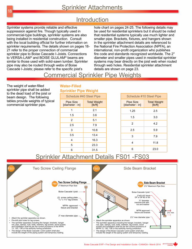
IntroductionSprinkler systems provide reliable and effective suppression against fire. Though typically used in commercial-type buildings, sprinkler systems are also being installed in residential construction. Consult with the local building official for further information on sprinkler requirements. The details shown on pages 18-21 refer to the proper connection of commercial sprinkler pipe to Boise Cascade I-Joists. Connections to VERSA-LAM® and BOISE GLULAM® beams are similar to those used with solid-sawn lumber. Sprinkler pipe may also be routed through webs of Boise Cascade I-Joists; please refer to the specific joist’s
hole chart on pages 24-25. The following details may be used for residential sprinklers but it should be noted that residential systems typically use much lighter and smaller pipe. Brackets, fixtures, and hangers shown in the sprinkler attachment details are referenced to the National Fire Protection Association (NPFA), an international, non-profit organization who publishes fire code and standards recognized worldwide. The 2" diameter and smaller pipes used in residential sprinkler systems may bear directly on the joist web when routed through web holes. Residential sprinkler attachment details are shown on page 23.
Commercial Sprinkler Pipe WeightsThe weight of water-filled sprinkler pipe shall be added to the dead load of the joist or beam design. The following tables provide weights of typical commercial sprinkler pipe.
Water-Filled Sprinkler Pipe Weight
Schedule #40 Steel Pipe
Pipe Size [diameter - in]
Total Weight [lb/ft]
1 2.1
1.5 3.6
2 5.1
2.5 7.9
3 10.8
3.5 13.4
4 16.3
5 23.3
6 31.5
Schedule #10 Steel Pipe
Pipe Size [diameter - in]
Total Weight [lb/ft]
1.25 2.5
1.5 3.0
2 4.2
2.5 5.9
3 7.9
4 11.8
6 23.0
Sprinkler Attachment Details FS01 -FS03
Two Screw Ceiling Flange Side Beam BracketFS01 FS03

Boise Cascade EWP • Fire Design and Installation Guide • CANADA • March 2014
19
LIMIT STATES DESIGN CANADA
Sprinkler Attachment Details FS04 -FS11
Eye Rod Hanger Eye Rod HangerFS04 FS06
I-Joist Hanger U HangerFS07 FS08
Inverted U Hanger U HangerFS09 FS11

20
Boise Cascade EWP • Fire Design and Installation Guide • CANADA • March 2014 LIMIT STATES DESIGN CANADA
Sprinkler Attachment Details FS12 -FS17
Inverted U Hanger Pipe StrapFS12 FS13
U Hanger
Pipe Strap
Inverted U Hanger
Seismic Bracing
FS14
FS16
FS15
FS17
Boise Cascade EWP • Fire Design and Installation Guide • CANADA • March 2014
21
LIMIT STATES DESIGN CANADA
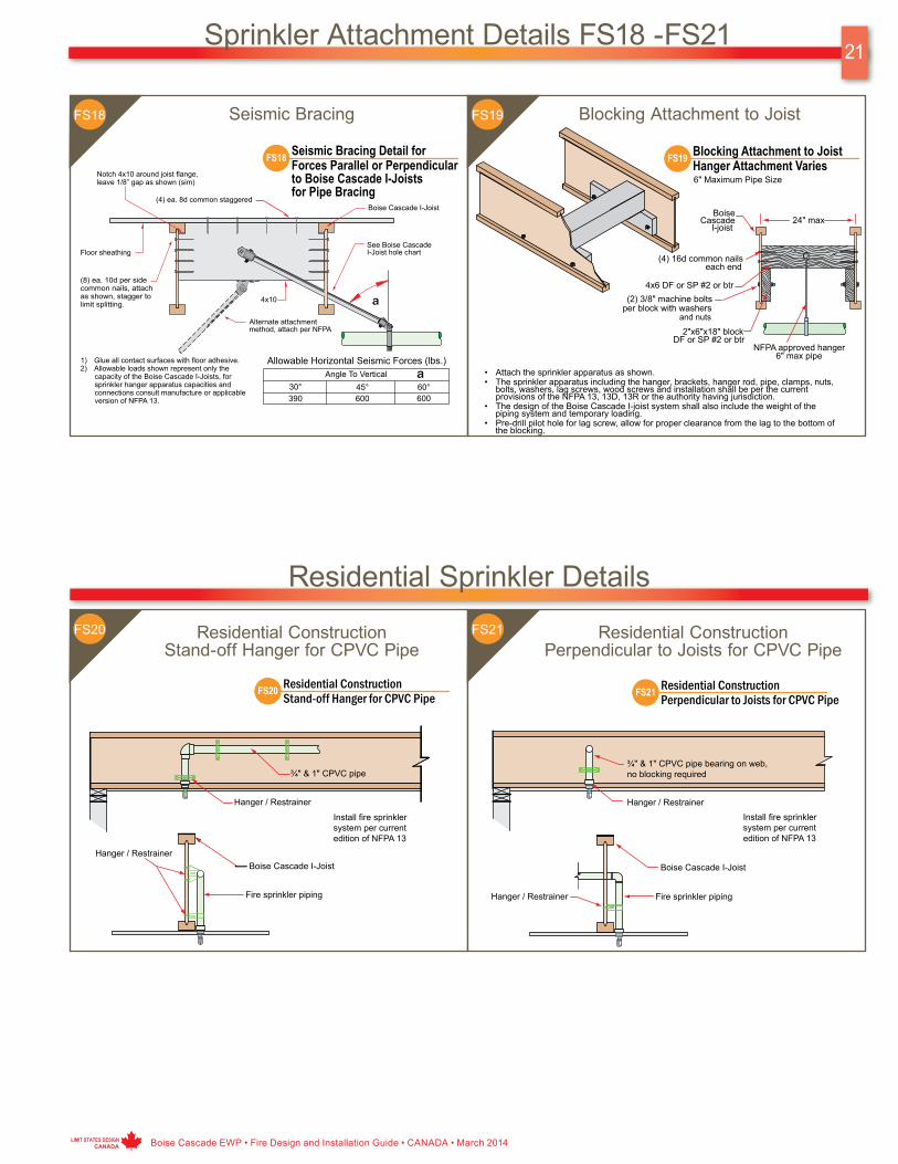
Sprinkler Attachment Details FS18 -FS21
Seismic Bracing Blocking Attachment to JoistFS18 FS19
FS21Residential ConstructionStand-off Hanger for CPVC Pipe
Residential ConstructionPerpendicular to Joists for CPVC Pipe
FS20
Residential Sprinkler Details

22
Boise Cascade EWP • Fire Design and Installation Guide • CANADA • March 2014 LIMIT STATES DESIGN CANADA
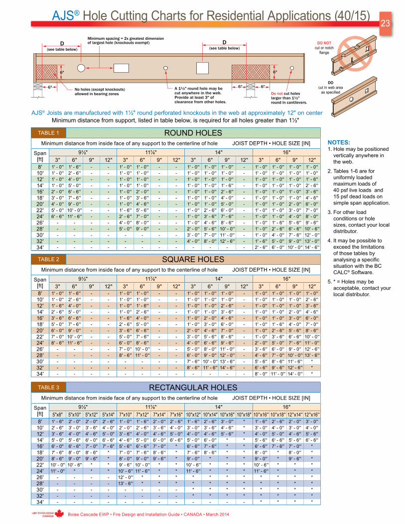
BCI® Hole Cutting Charts for Residential Applications (40/15)
DO cut in web area
as specified
DO NOT cut or notch
flange
TABLE 1 ROUND HOLESMinimum distance from inside face of any support to centerline of hole JOIST DEPTH • HOLE SIZE [IN]
Span[ft]
9½" 11⅞" 14" 16"3" 6" 9" 12" 3" 6" 9" 12" 3" 6" 9" 12" 3" 6" 9" 12"
8' 1' - 0'' 1' - 0'' - - 1' - 0'' 1' - 0'' - - 1' - 0'' 1' - 0'' 1' - 0'' - 1' - 0'' 1' - 0'' 1' - 0'' 1' - 0''10' 1' - 0'' 1' - 0'' - - 1' - 0'' 1' - 0'' - - 1' - 0'' 1' - 0'' 1' - 0'' - 1' - 0'' 1' - 0'' 1' - 0'' 1' - 0''12' 1' - 0'' 2' - 0'' - - 1' - 0'' 1' - 0'' - - 1' - 0'' 1' - 0'' 1' - 0'' - 1' - 0'' 1' - 0'' 1' - 0'' 1' - 0''14' 1' - 0'' 3' - 0'' - - 1' - 0'' 1' - 0'' - - 1' - 0'' 1' - 0'' 1' - 0'' - 1' - 0'' 1' - 0'' 1' - 0'' 2' - 0''16' 1' - 0'' 4' - 0'' - - 1' - 0'' 1' - 0'' - - 1' - 0'' 1' - 0'' 2' - 0'' - 1' - 0'' 1' - 0'' 1' - 0'' 3' - 0''18' 1' - 0'' 5' - 0'' - - 1' - 0'' 2' - 0'' - - 1' - 0'' 1' - 0'' 3' - 0'' - 1' - 0'' 1' - 0'' 1' - 0'' 4' - 0''20' 1' - 6'' 6' - 6'' - - 1' - 0'' 3' - 0'' - - 1' - 0'' 1' - 0'' 4' - 0'' - 1' - 0'' 1' - 0'' 2' - 0'' 5' - 0''22' 2' - 6'' 7' - 6'' - - 1' - 0'' 4' - 0'' - - 1' - 0'' 1' - 6'' 5' - 6'' - 1' - 0'' 1' - 0'' 3' - 0'' 6' - 6''24' 3' - 6'' 9' - 0'' - - 1' - 6'' 5' - 6'' - - 1' - 0'' 2' - 6'' 6' - 6'' - 1' - 0'' 1' - 0'' 4' - 0'' 7' - 6''26' - - - - 2' - 6'' 6' - 6'' - - 1' - 0'' 4' - 0'' 7' - 6'' - 1' - 0'' 2' - 0'' 5' - 0'' 9' - 0''28' - - - - 3' - 6'' 7' - 6'' - - 1' - 6'' 5' - 0'' 9' - 0'' - 1' - 0'' 3' - 0'' 6' - 6'' 10' - 0''30' - - - - - - - - 2' - 6'' 6' - 0'' 10' - 0'' - 1' - 0'' 4' - 0'' 7' - 6'' 11' - 6''32' - - - - - - - - 3' - 6'' 7' - 0'' 11' - 6'' - 2' - 0'' 5' - 0'' 8' - 6'' 12' - 6''34' - - - - - - - - - - - - 3' - 0'' 6' - 0'' 10' - 0'' 14' - 0''
TABLE 2 SQUARE HOLESMinimum distance from inside face of any support to centerline of hole JOIST DEPTH • HOLE SIZE [IN]
Span[ft]
9½" 11⅞" 14" 16"3" 6" 9" 12" 3" 6" 9" 12" 3" 6" 9" 12" 3" 6" 9" 12"
8' 1' - 0'' 1' - 0'' - - 1' - 0'' 1' - 0'' - - 1' - 0'' 1' - 0'' 1' - 0'' - 1' - 0'' 1' - 0'' 1' - 0'' 1' - 0''10' 1' - 0'' 1' - 6'' - - 1' - 0'' 1' - 0'' - - 1' - 0'' 1' - 0'' 1' - 0'' - 1' - 0'' 1' - 0'' 1' - 0'' 2' - 0''12' 1' - 0'' 2' - 6'' - - 1' - 0'' 1' - 0'' - - 1' - 0'' 1' - 0'' 2' - 0'' - 1' - 0'' 1' - 0'' 1' - 0'' 3' - 6''14' 1' - 0'' 3' - 6'' - - 1' - 0'' 2' - 0'' - - 1' - 0'' 1' - 0'' 3' - 0'' - 1' - 0'' 1' - 0'' 2' - 0'' 4' - 6''16' 2' - 0'' 4' - 6'' - - 1' - 0'' 3' - 0'' - - 1' - 0'' 1' - 6'' 4' - 0'' - 1' - 0'' 1' - 0'' 3' - 0'' 6' - 0''18' 3' - 0'' 6' - 0'' - - 2' - 0'' 4' - 0'' - - 1' - 0'' 3' - 0'' 5' - 6'' - 1' - 0'' 1' - 6'' 4' - 0'' 7' - 0''20' 4' - 0'' 7' - 0'' - - 3' - 0'' 5' - 6'' - - 1' - 6'' 4' - 0'' 6' - 6'' - 1' - 0'' 3' - 0'' 5' - 6'' 8' - 6''22' 5' - 0'' 8' - 6'' - - 4' - 0'' 6' - 6'' - - 2' - 6'' 5' - 0'' 8' - 0'' - 1' - 6'' 4' - 0'' 6' - 6'' 9' - 6''24' 6' - 6'' 9' - 6'' - - 5' - 0'' 8' - 0'' - - 3' - 6'' 6' - 0'' 9' - 0'' - 2' - 6'' 5' - 0'' 8' - 0'' 11' - 0''26' - - - - 6' - 0'' 9' - 0'' - - 5' - 0'' 7' - 6'' 10' - 6'' - 3' - 6'' 6' - 0'' 9' - 0'' 12' - 0''28' - - - - 7' - 6'' 10' - 6'' - - 6' - 0'' 8' - 6'' 11' - 6'' - 5' - 0'' 7' - 6'' 10' - 0'' 13' - 6''30' - - - - - - - - 7' - 0'' 10' - 0'' 13' - 0'' - 6' - 0'' 8' - 6'' 11' - 6'' 14' - 6''32' - - - - - - - - 8' - 0'' 11' - 0'' 14' - 0'' - 7' - 0'' 10' - 0'' 12' - 6'' *34' - - - - - - - - - - - - 8' - 6'' 11' - 0'' 14' - 0'' *
TABLE 3 RECTANGULAR HOLESMinimum distance from inside face of any support to centerline of hole JOIST DEPTH • HOLE SIZE [IN]
Span[ft]
9½" 11⅞" 14" 16"5"x8" 5"x10" 5"x12" 5"x14" 7"x10" 7"x12" 7"x14" 7"x16" 10"x12" 10"x14" 10"x16"10"x18" 12"x14" 12"x16" 12"x18"12"x20"
8' 1' - 0'' 1' - 0'' 1' - 6'' 2' - 0'' 1' - 0'' 1' - 6'' 2' - 0'' 2' - 6'' 1' - 6'' 2' - 0'' 3' - 0'' * 2' - 0'' 3' - 0'' * *10' 1' - 6'' 2' - 0'' 2' - 6'' 3' - 0'' 2' - 0'' 2' - 6'' 3' - 0'' 3' - 6'' 2' - 6'' 3' - 6'' 4' - 6'' * 3' - 6'' 4' - 0'' * *12' 2' - 6'' 3' - 0'' 4' - 0'' 4' - 6'' 3' - 0'' 3' - 6'' 4' - 6'' 5' - 0'' 4' - 0'' 4' - 6'' 5' - 6'' * 4' - 6'' 5' - 6'' * *14' 4' - 0'' 4' - 6'' 5' - 0'' 5' - 6'' 4' - 0'' 5' - 0'' 5' - 6'' 6' - 6'' 5' - 0'' 6' - 0'' * * 6' - 0'' 6' - 6'' * *16' 5' - 0'' 5' - 6'' 6' - 6'' 7' - 0'' 5' - 6'' 6' - 0'' 7' - 0'' 7' - 6'' 6' - 6'' 7' - 0'' * * 7' - 0'' * * *18' 6' - 0'' 7' - 0'' 7' - 6'' 8' - 6'' 6' - 6'' 7' - 6'' 8' - 0'' * 7' - 6'' 8' - 6'' * * 8' - 6'' * * *20' 7' - 6'' 8' - 0'' 9' - 0'' 9' - 6'' 8' - 0'' 8' - 6'' 9' - 6'' * 9' - 0'' * * * 9' - 6'' * * *22' 8' - 6'' 9' - 6'' 10' - 0'' * 9' - 0'' 10' - 0'' 10' - 6'' * 10' - 0'' * * * * * * *24' 10' - 0'' 10' - 6'' 11' - 6'' * 10' - 6'' 11' - 0'' * * 11' - 6'' * * * * * * *26' - - - - 11' - 6'' 12' - 6'' * * * * * * * * * *28' - - - - 13' - 0'' 13' - 6'' * * * * * * * * * *30' - - - - - - - - * * * * * * * *32' - - - - - - - - * * * * * * * *34' - - - - - - - - - - - - * * * *
NOTES
1. Hole may be positioned vertically anywhere in the web.
2. Tables 1-3 are for uniformly loaded maximum loads of 40 psf live loads and 15 psf dead loads on simple span application.
3. For other load conditions or hole sizes, contact your local distributor.
4. It may be possible to exceed the limitations of those tables by analysing a specific situation with the BC CALC® Software.
5. * = Holes may be acceptable, contact your local distributor.
BCI® Joists are manufactured with 1½" round perforated knockouts in the web at approximately 12" on centerMinimum distance from support, listed in table below, is required for all holes greater than 1½"
Boise Cascade EWP • Fire Design and Installation Guide • CANADA • March 2014
23
LIMIT STATES DESIGN CANADA
AJS® Hole Cutting Charts for Residential Applications (40/15)
AJS® Joists are manufactured with 1½" round perforated knockouts in the web at approximately 12" on center
DO cut in web area
as specified
DO NOT cut or notch
flange
Minimum distance from support, listed in table below, is required for all holes greater than 1½"
TABLE 1 ROUND HOLESMinimum distance from inside face of any support to the centerline of hole JOIST DEPTH • HOLE SIZE [IN]
Span[ft]
9½" 11⅞" 14" 16"3" 6" 9" 12" 3" 6" 9" 12" 3" 6" 9" 12" 3" 6" 9" 12"
8' 1' - 0'' 1' - 6'' - - 1' - 0'' 1' - 0'' - - 1' - 0'' 1' - 0'' 1' - 0'' - 1' - 0'' 1' - 0'' 1' - 0'' 1' - 0''10' 1' - 0'' 2' - 6'' - - 1' - 0'' 1' - 0'' - - 1' - 0'' 1' - 0'' 1' - 0'' - 1' - 0'' 1' - 0'' 1' - 0'' 1' - 0''12' 1' - 0'' 4' - 0'' - - 1' - 0'' 1' - 0'' - - 1' - 0'' 1' - 0'' 1' - 0'' - 1' - 0'' 1' - 0'' 1' - 0'' 1' - 6''14' 1' - 0'' 5' - 0'' - - 1' - 0'' 1' - 0'' - - 1' - 0'' 1' - 0'' 1' - 6'' - 1' - 0'' 1' - 0'' 1' - 0'' 2' - 6''16' 2' - 0'' 6' - 6'' - - 1' - 0'' 2' - 0'' - - 1' - 0'' 1' - 0'' 2' - 6'' - 1' - 0'' 1' - 0'' 1' - 0'' 3' - 6''18' 3' - 0'' 7' - 6'' - - 1' - 0'' 3' - 6'' - - 1' - 0'' 1' - 0'' 4' - 0'' - 1' - 0'' 1' - 0'' 1' - 0'' 4' - 6''20' 4' - 0'' 9' - 0'' - - 1' - 0'' 4' - 6'' - - 1' - 0'' 1' - 0'' 5' - 0'' - 1' - 0'' 1' - 0'' 2' - 0'' 6' - 0''22' 5' - 0'' 10' - 0'' - - 1' - 6'' 5' - 6'' - - 1' - 0'' 2' - 6'' 6' - 0'' - 1' - 0'' 1' - 0'' 3' - 0'' 7' - 0''24' 6' - 6'' 11' - 6'' - - 2' - 6'' 7' - 0'' - - 1' - 0'' 3' - 6'' 7' - 6'' - 1' - 0'' 1' - 0'' 4' - 0'' 8' - 0''26' - - - - 4' - 0'' 8' - 0'' - - 1' - 0'' 4' - 6'' 8' - 6'' - 1' - 0'' 1' - 6'' 5' - 6'' 9' - 6''28' - - - - 5' - 0'' 9' - 0'' - - 2' - 0'' 5' - 6'' 10' - 0'' - 1' - 0'' 2' - 6'' 6' - 6'' 10' - 6''30' - - - - - - - - 3' - 0'' 7' - 0'' 11' - 0'' - 1' - 0'' 4' - 0'' 7' - 6'' 12' - 0''32' - - - - - - - - 4' - 0'' 8' - 0'' 12' - 6'' - 1' - 6'' 5' - 0'' 9' - 0'' 13' - 0''34' - - - - - - - - - - - - 2' - 6'' 6' - 0'' 10' - 0'' 14' - 6''
TABLE 2 SQUARE HOLESMinimum distance from inside face of any support to the centerline of hole JOIST DEPTH • HOLE SIZE [IN]
Span[ft]
9½" 11⅞" 14" 16"3" 6" 9" 12" 3" 6" 9" 12" 3" 6" 9" 12" 3" 6" 9" 12"
8' 1' - 0'' 1' - 6'' - - 1' - 0'' 1' - 0'' - - 1' - 0'' 1' - 0'' 1' - 0'' - 1' - 0'' 1' - 0'' 1' - 0'' 1' - 0''10' 1' - 0'' 2' - 6'' - - 1' - 0'' 1' - 0'' - - 1' - 0'' 1' - 0'' 1' - 0'' - 1' - 0'' 1' - 0'' 1' - 0'' 2' - 6''12' 1' - 6'' 4' - 0'' - - 1' - 0'' 1' - 6'' - - 1' - 0'' 1' - 0'' 2' - 6'' - 1' - 0'' 1' - 0'' 1' - 0'' 3' - 6''14' 2' - 6'' 5' - 0'' - - 1' - 0'' 2' - 6'' - - 1' - 0'' 1' - 0'' 3' - 6'' - 1' - 0'' 1' - 0'' 2' - 0'' 4' - 6''16' 3' - 6'' 6' - 6'' - - 1' - 6'' 4' - 0'' - - 1' - 0'' 2' - 0'' 4' - 6'' - 1' - 0'' 1' - 0'' 3' - 0'' 6' - 0''18' 5' - 0'' 7' - 6'' - - 2' - 6'' 5' - 0'' - - 1' - 0'' 3' - 0'' 6' - 0'' - 1' - 0'' 1' - 6'' 4' - 0'' 7' - 0''20' 6' - 0'' 9' - 0'' - - 3' - 6'' 6' - 6'' - - 2' - 0'' 4' - 6'' 7' - 0'' - 1' - 0'' 2' - 6'' 5' - 6'' 8' - 6''22' 7' - 0'' 10' - 0'' - - 5' - 0'' 7' - 6'' - - 3' - 0'' 5' - 6'' 8' - 6'' - 1' - 0'' 3' - 6'' 6' - 6'' 10' - 0''24' 8' - 6'' 11' - 6'' - - 6' - 0'' 8' - 6'' - - 4' - 0'' 6' - 6'' 9' - 6'' - 2' - 0'' 5' - 0'' 7' - 6'' 11' - 0''26' - - - - 7' - 0'' 10' - 0'' - - 5' - 0'' 8' - 0'' 11' - 0'' - 3' - 6'' 6' - 0'' 9' - 0'' 12' - 6''28' - - - - 8' - 6'' 11' - 0'' - - 6' - 0'' 9' - 0'' 12' - 0'' - 4' - 6'' 7' - 0'' 10' - 0'' 13' - 6''30' - - - - - - - - 7' - 6'' 10' - 0'' 13' - 6'' - 5' - 6'' 8' - 6'' 11' - 6'' *32' - - - - - - - - 8' - 6'' 11' - 6'' 14' - 6'' - 6' - 6'' 9' - 6'' 12' - 6'' *34' - - - - - - - - - - - - 8' - 0'' 11' - 0'' 14' - 0'' *
TABLE 3 RECTANGULAR HOLESMinimum distance from inside face of any support to the centerline of hole JOIST DEPTH • HOLE SIZE [IN]
Span[ft]
9½" 11⅞" 14" 16"5"x8" 5"x10" 5"x12" 5"x14" 7"x10" 7"x12" 7"x14" 7"x16" 10"x12" 10"x14" 10"x16" 10"x18" 10''x16'' 10''x18'' 12''x14'' 12''x16''
8' 1' - 6'' 2' - 0'' 2' - 0'' 2' - 6'' 1' - 0'' 1' - 6'' 2' - 0'' 2' - 6'' 1' - 6'' 2' - 6'' 3' - 0'' * 1' - 6'' 2' - 6'' 2' - 0'' 3' - 0''10' 2' - 6'' 3' - 0'' 3' - 6'' 4' - 0'' 2' - 0'' 2' - 6'' 3' - 6'' 4' - 0'' 3' - 0'' 3' - 6'' 4' - 6'' * 3' - 0'' 4' - 0'' 3' - 0'' 4' - 0''12' 3' - 6'' 4' - 0'' 4' - 6'' 5' - 0'' 3' - 6'' 4' - 0'' 4' - 6'' 5' - 0'' 4' - 0'' 4' - 6'' 5' - 6'' * 4' - 0'' 5' - 0'' 4' - 6'' 5' - 6''14' 5' - 0'' 5' - 6'' 6' - 0'' 6' - 6'' 4' - 6'' 5' - 0'' 6' - 0'' 6' - 6'' 5' - 0'' 6' - 0'' * * 5' - 6'' 6' - 6'' 5' - 6'' 6' - 6''16' 6' - 0'' 6' - 6'' 7' - 0'' 7' - 6'' 5' - 6'' 6' - 6'' 7' - 0'' * 6' - 6'' 7' - 6'' * * 6' - 6'' 7' - 6'' 7' - 0'' *18' 7' - 6'' 8' - 0'' 8' - 6'' * 7' - 0'' 7' - 6'' 8' - 6'' * 7' - 6'' 8' - 6'' * * 8' - 0'' * 8' - 0'' *20' 8' - 6'' 9' - 0'' 9' - 6'' * 8' - 0'' 9' - 0'' 9' - 6'' * 9' - 0'' * * * 9' - 0'' * 9' - 6'' *22' 10' - 0'' 10' - 6'' * * 9' - 6'' 10' - 0'' * * 10' - 6'' * * * 10' - 6'' * * *24' 11' - 0'' * * * 10' - 6'' 11' - 6'' * * 11' - 6'' * * * 11' - 6'' * * *26' - - - - 12' - 0'' * * * * * * * * * * *28' - - - - 13' - 6'' * * * * * * * * * * *30' - - - - - - - - * * * * * * * *32' - - - - - - - - * * * * * * * *34' - - - - - - - - - - - - * * * *
NOTES:1. Hole may be positioned
vertically anywhere in the web.
2. Tables 1-6 are for uniformly loaded maximum loads of 40 psf live loads and 15 psf dead loads on simple span application.
3. For other load conditions or hole sizes, contact your local distributor.
4. It may be possible to exceed the limitations of those tables by analysing a specific situation with the BC CALC® Software.
5. * = Holes may be acceptable, contact your local distributor.

24
Boise Cascade EWP • Fire Design and Installation Guide • CANADA • March 2014 LIMIT STATES DESIGN CANADA
AJS® Hole Cutting Charts for Residential Applications (40/15)
TABLE 4 ROUND HOLESMinimum distance from inside face of any support to the centerline of hole JOIST DEPTH • HOLE SIZE [IN]
Span[ft]
18" 20" 22" 24"3'' 6'' 9'' 12'' 6'' 9'' 12'' 15'' 6'' 9'' 12'' 15'' 9'' 12'' 15'' 18''
8' 1' - 0'' 1' - 0'' 1' - 0'' 1' - 0'' 1' - 0'' 1' - 0'' 1' - 0'' 2' - 0'' 1' - 0'' 1' - 0'' 1' - 0'' 1' - 0'' 1' - 0'' 1' - 0'' 1' - 0'' 1' - 0''10' 1' - 0'' 1' - 0'' 1' - 0'' 1' - 0'' 1' - 0'' 1' - 0'' 1' - 0'' 3' - 6'' 1' - 0'' 1' - 0'' 1' - 0'' 1' - 0'' 1' - 0'' 1' - 0'' 1' - 0'' 1' - 0''12' 1' - 0'' 1' - 0'' 1' - 0'' 2' - 6'' 1' - 0'' 1' - 0'' 1' - 0'' 4' - 6'' 1' - 0'' 1' - 0'' 1' - 0'' 1' - 0'' 1' - 0'' 1' - 0'' 1' - 0'' 2' - 0''14' 1' - 0'' 1' - 0'' 1' - 0'' 3' - 6'' 1' - 0'' 1' - 0'' 1' - 0'' 6' - 0'' 1' - 0'' 1' - 0'' 1' - 0'' 1' - 6'' 1' - 0'' 1' - 0'' 1' - 0'' 3' - 6''16' 1' - 0'' 1' - 0'' 1' - 0'' 4' - 6'' 1' - 0'' 1' - 0'' 1' - 0'' 7' - 0'' 1' - 0'' 1' - 0'' 1' - 0'' 2' - 6'' 1' - 0'' 1' - 0'' 1' - 0'' 4' - 6''18' 1' - 0'' 1' - 0'' 1' - 0'' 6' - 0'' 1' - 0'' 1' - 0'' 1' - 6'' 8' - 6'' 1' - 0'' 1' - 0'' 1' - 0'' 3' - 6'' 1' - 0'' 1' - 0'' 1' - 0'' 5' - 6''20' 1' - 0'' 1' - 0'' 1' - 0'' 7' - 0'' 1' - 0'' 1' - 0'' 2' - 6'' 9' - 6'' 1' - 0'' 1' - 0'' 1' - 0'' 5' - 0'' 1' - 0'' 1' - 0'' 1' - 0'' 7' - 0''22' 1' - 0'' 1' - 0'' 1' - 6'' 8' - 6'' 1' - 0'' 1' - 0'' 3' - 6'' * 1' - 0'' 1' - 0'' 1' - 0'' 6' - 0'' 1' - 0'' 1' - 0'' 2' - 0'' 8' - 0''24' 1' - 0'' 1' - 0'' 2' - 6'' 9' - 6'' 1' - 0'' 1' - 0'' 5' - 0'' * 1' - 0'' 1' - 0'' 1' - 0'' 7' - 0'' 1' - 0'' 1' - 0'' 3' - 6'' 9' - 6''26' 1' - 0'' 1' - 0'' 3' - 6'' 11' - 0'' 1' - 0'' 1' - 0'' 6' - 0'' * 1' - 0'' 1' - 0'' 2' - 6'' 8' - 6'' 1' - 0'' 1' - 0'' 4' - 6'' 10' - 6''28' 1' - 0'' 1' - 0'' 4' - 6'' 12' - 0'' 1' - 0'' 1' - 0'' 7' - 0'' * 1' - 0'' 1' - 0'' 3' - 6'' 9' - 6'' 1' - 0'' 1' - 0'' 5' - 6'' 12' - 0''30' 1' - 0'' 1' - 0'' 5' - 6'' 13' - 6'' 1' - 0'' 2' - 0'' 8' - 6'' * 1' - 0'' 1' - 0'' 4' - 6'' 11' - 0'' 1' - 0'' 1' - 0'' 6' - 6'' 13' - 0''32' 1' - 0'' 1' - 0'' 7' - 0'' 14' - 6'' 1' - 0'' 3' - 0'' 9' - 6'' * 1' - 0'' 1' - 0'' 5' - 6'' 12' - 0'' 1' - 0'' 2' - 6'' 8' - 0'' 14' - 6''34' 1' - 0'' 1' - 6'' 8' - 0'' 16' - 0'' 1' - 0'' 4' - 6'' 11' - 0'' * 1' - 0'' 1' - 0'' 6' - 6'' 13' - 6'' 1' - 0'' 3' - 6'' 9' - 0'' 15' - 6''
AJS® Joists are manufactured with 1½" round perforated knockouts in the web at approximately 12" on centerMinimum distance from support, listed in table below, is required for all holes greater than 1½"
TABLE 5 SQUARE HOLESMinimum distance from inside face of any support to the centerline of hole JOIST DEPTH • HOLE SIZE [IN]
Span[ft]
18" 20" 22" 24"3'' 6'' 9'' 12'' 6'' 9'' 12'' 15'' 6'' 9'' 12'' 15'' 9'' 12'' 15'' 18''
8' 1' - 0'' 1' - 0'' 1' - 0'' 1' - 0'' 1' - 0'' 1' - 0'' 1' - 0'' 1' - 6'' 1' - 0'' 1' - 0'' 1' - 0'' 1' - 0'' 1' - 0'' 1' - 0'' 1' - 0'' 3' - 0''10' 1' - 0'' 1' - 0'' 1' - 0'' 1' - 0'' 1' - 0'' 1' - 0'' 1' - 0'' 3' - 0'' 1' - 0'' 1' - 0'' 1' - 0'' 1' - 6'' 1' - 0'' 1' - 0'' 1' - 0'' 4' - 6''12' 1' - 0'' 1' - 0'' 1' - 0'' 1' - 6'' 1' - 0'' 1' - 0'' 1' - 0'' 4' - 0'' 1' - 0'' 1' - 0'' 1' - 0'' 2' - 6'' 1' - 0'' 1' - 0'' 1' - 6'' 5' - 6''14' 1' - 0'' 1' - 0'' 1' - 0'' 3' - 0'' 1' - 0'' 1' - 0'' 1' - 6'' 5' - 6'' 1' - 0'' 1' - 0'' 1' - 0'' 4' - 0'' 1' - 0'' 1' - 0'' 2' - 6'' *16' 1' - 0'' 1' - 0'' 1' - 0'' 4' - 0'' 1' - 0'' 1' - 0'' 2' - 6'' 6' - 6'' 1' - 0'' 1' - 0'' 1' - 6'' 5' - 0'' 1' - 0'' 1' - 0'' 4' - 0'' *18' 1' - 0'' 1' - 0'' 1' - 6'' 5' - 0'' 1' - 0'' 1' - 0'' 3' - 6'' 8' - 0'' 1' - 0'' 1' - 0'' 2' - 6'' 6' - 6'' 1' - 0'' 1' - 6'' 5' - 0'' *20' 1' - 0'' 1' - 0'' 2' - 6'' 6' - 6'' 1' - 0'' 1' - 6'' 5' - 0'' 9' - 0'' 1' - 0'' 1' - 0'' 3' - 6'' 7' - 6'' 1' - 0'' 2' - 6'' 6' - 0'' *22' 1' - 0'' 1' - 0'' 3' - 6'' 7' - 6'' 1' - 0'' 2' - 6'' 6' - 0'' 10' - 6'' 1' - 0'' 1' - 0'' 4' - 6'' 9' - 0'' 1' - 0'' 3' - 6'' 7' - 6'' *24' 1' - 0'' 1' - 6'' 5' - 0'' 9' - 0'' 1' - 0'' 3' - 6'' 7' - 0'' 11' - 6'' 1' - 0'' 2' - 0'' 6' - 0'' 10' - 0'' 1' - 0'' 4' - 6'' 8' - 6'' *26' 1' - 0'' 2' - 6'' 6' - 0'' 10' - 0'' 1' - 0'' 4' - 6'' 8' - 6'' * 1' - 0'' 3' - 0'' 7' - 0'' 11' - 6'' 2' - 0'' 5' - 6'' 10' - 0'' *28' 1' - 0'' 3' - 6'' 7' - 0'' 11' - 6'' 2' - 0'' 5' - 6'' 9' - 6'' * 1' - 0'' 4' - 6'' 8' - 0'' 12' - 6'' 3' - 0'' 7' - 0'' 11' - 0'' *30' 1' - 0'' 4' - 6'' 8' - 6'' 12' - 6'' 3' - 0'' 7' - 0'' 11' - 0'' * 2' - 0'' 5' - 6'' 9' - 6'' 14' - 0'' 4' - 0'' 8' - 0'' 12' - 6'' *32' 2' - 6'' 5' - 6'' 9' - 6'' 14' - 0'' 4' - 6'' 8' - 0'' 12' - 0'' * 3' - 0'' 6' - 6'' 10' - 6'' 15' - 0'' 5' - 6'' 9' - 0'' 13' - 6'' *34' 3' - 6'' 7' - 0'' 10' - 6'' 15' - 0'' 5' - 6'' 9' - 0'' 13' - 6'' * 4' - 0'' 7' - 6'' 12' - 0'' 16' - 6'' 6' - 6'' 10' - 6'' 15' - 0'' *
TABLE 6 RECTANGULAR HOLESMinimum distance from inside face of any support to the centerline of hole JOIST DEPTH • HOLE SIZE [IN]
Span[ft]
18" 20" 22" 24"10''x18'' 12''x14'' 12''x16'' 12''x18'' 12''x16'' 12''x18'' 14''x16'' 14''x18'' 12''x18'' 14''x16'' 14''x18'' 16''x18'' 14''x18'' 14''x20'' 16''x18'' 16''x20''
8' 1' - 6'' 1' - 0'' 1' - 6'' 3' - 0'' 1' - 0'' 1' - 6'' 1' - 6'' 3' - 0'' 1' - 0'' 1' - 0'' 2' - 0'' 3' - 0'' 1' - 0'' 2' - 0'' 2' - 0'' 3' - 6''10' 2' - 6'' 1' - 6'' 3' - 0'' 4' - 0'' 1' - 6'' 3' - 0'' 3' - 0'' 4' - 6'' 2' - 0'' 1' - 6'' 3' - 0'' 4' - 6'' 2' - 0'' 3' - 6'' 3' - 0'' *12' 4' - 0'' 3' - 0'' 4' - 0'' 5' - 6'' 2' - 6'' 4' - 0'' 4' - 0'' 5' - 6'' 3' - 0'' 3' - 0'' 4' - 0'' 5' - 6'' 3' - 0'' 4' - 6'' 4' - 6'' *14' 5' - 0'' 4' - 0'' 5' - 6'' 6' - 6'' 4' - 0'' 5' - 6'' 5' - 6'' * 4' - 0'' 4' - 0'' 5' - 6'' * 4' - 0'' 6' - 0'' 5' - 6'' *16' 6' - 6'' 5' - 0'' 6' - 6'' * 5' - 0'' 6' - 6'' 6' - 6'' * 5' - 6'' 5' - 0'' 6' - 6'' * 5' - 6'' 7' - 0'' 7' - 0'' *18' 7' - 6'' 6' - 6'' 8' - 0'' * 6' - 6'' 8' - 0'' 8' - 0'' * 6' - 6'' 6' - 6'' 8' - 0'' * 6' - 6'' 8' - 6'' 8' - 0'' *20' 9' - 0'' 7' - 6'' 9' - 0'' * 7' - 6'' 9' - 0'' 9' - 0'' * 7' - 6'' 7' - 6'' 9' - 0'' * 8' - 0'' 9' - 6'' 9' - 6'' *22' 10' - 0'' 9' - 0'' 10' - 6'' * 9' - 0'' 10' - 6'' 10' - 6'' * 9' - 0'' 9' - 0'' 10' - 6'' * 9' - 0'' * 10' - 6'' *24' 11' - 6'' 10' - 0'' 11' - 6'' * 10' - 0'' 11' - 6'' 11' - 6'' * 10' - 6'' 10' - 0'' * * 10' - 6'' * * *26' 12' - 6'' 11' - 6'' * * 11' - 6'' * * * 11' - 6'' 11' - 6'' * * 11' - 6'' * * *28' * 12' - 6'' * * 12' - 6'' * * * 13' - 0'' 12' - 6'' * * 13' - 0'' * * *30' * 14' - 0'' * * 14' - 0'' * * * 14' - 0'' 14' - 0'' * * 14' - 6'' * * *32' * 15' - 6'' * * 15' - 0'' * * * 15' - 6'' 15' - 6'' * * 15' - 6'' * * *34' * 16' - 6'' * * 16' - 6'' * * * 16' - 6'' 16' - 6'' * * * * * *
NOTES:1. Hole may be positioned
vertically anywhere in the web.
2. Tables 1-6 are for uniformly loaded maximum loads of 40 psf live loads and 15 psf dead loads on simple span application.
3. For other load conditions or hole sizes, contact your local distributor.
4. It may be possible to exceed the limitations of those tables by analysing a specific situation with the BC CALC® Software.
5. * = Holes may be acceptable, contact your local distributor.
DO cut in web area
as specified
DO NOT cut or notch
flange

Boise Cascade EWP • Fire Design and Installation Guide • CANADA • March 2014
25
LIMIT STATES DESIGN CANADA
Q: What is the Smoke Developed Classification?A: The smoke developed classification is a measure of the concentration of smoke a material emits as it burns. VERSA-LAM® has a smoke index of 105, which is lower than most wood structural panels.
Q: What is the difference between Type X and Type C gypsum board?
A: Fire-rated gypsum board is typically available in two separate types, X and C. When exposed to heat, water evaporates from the gypsum and the particles shrink. This causes the gypsum particles to lose their bond and the board disintegrates. In Type X gypsum board, glass fiber is mixed with gypsum during the manufacturing process. The glass fiber acts as reinforcement, increasing the board’s structural capacity for a longer period of time during exposure to fire. Vermiculite ore is added with glass fiber in the production of Type C gypsum board. The vermiculite ore expands with an increase in temperature, in affect counteracting the shrinkage of the gypsum particles. Thus, Type C provides greater fire resistance than Type X. It is very important that the design professional of record specifies the correct type of fire-rated gypsum board per the floor/ceiling assemblies shown on pages 7-13.
Q: Are the adhesives in EWP products fire rated?A: The adhesives used in Boise Cascade EWP products have been extensively tested according to current American Society for Testing and Materials (ASTM) and Canadian Standards Association (CSA) specifications to ensure structural, moisture durability, and heat durability performance.
Q: What is a flame spread rating?A: A flame spread rating is used to assess the surface flammability of building materials and interior finish products by measuring the rate that flame travels across the surface of a material. The level of NBCC requirements for flame-spread ratings is relative to the importance of a space as a means of escape. The more essential the space is as a link to safety for a greater number of occupants in the building, the more restrictive the requirements. It should be noted that flame spread is only a surface measurement and cannot be used to determine the fire resistance of a structural component. Most wood products including Boise Cascade VERSA-LAM®, BCI® and AJS® Joists, Rimboard and BOISE GLULAM® Beams have a flame-spread rating of less than 150 as required by the NBCC.
Q: Are Boise Cascade EWP products available with a fire-retardant treatment?
A: Boise Cascade does not manufacture any BCI®, AJS® or VERSA-LAM® with a fire-retardant treatment and does not allow the products to be pressure-treated by a third-party. Fire-retardant pressure treatments typically reduce the strength and stiffness of the wood. There are some topical treatments on the market for wood that claim to provide a reduced flame spread rating. Boise Cascade has not tested any of these products to substantiate any of the claims made by these treatments and the claims of flame spread rating for these treatments is the responsibility of the treatment manufacturer.
Q: Do Boise Cascade fire assemblies have a UL® listing?
A: Underwriters Laboratories® is one of several product certification bodies accredited by The Standards Council of Canada that provides certification for the fire-resistance of building materials and elements. The fire-endurance rated assemblies in this guide have been tested in accordance with ASTM E119 and CAN\ULC-S101 and certified by APA – The Engineered Wood Association; a Standards Council of Canada accredited certification body. A complete listing of Boise Cascade fire-endurance rated assemblies can be obtained from APA – The Engineered Wood Association at the following web address: www.apawood.org/level_b.cfm?content=prd_rept_main.
Q: What is mineral fiber insulation and how is it specified?
A: Mineral fiber insulation is a fire resistive material composed principally of fibers manufactured from rock, slag, or glass, with or without binders. Mineral fiber insulation is typically used in one-hour floor ceiling assemblies that utilize a single layer of gypsum board (see details on pages 9-13). The mineral fiber insulation batts are basically a fire resistant substitute for the second layer of gypsum board, in order to maintain a one-hour fire rating. Mineral fiber insulation is specified in a thickness (inches) and density (pounds per cubic foot). Though the specified material dimensions should be followed in constructing assemblies, equivalent mineral fiber insulation may be substituted per approval of the project’s design professional of record and Boise Cascade EWP Engineering. For example, if 2" thick - 3.5 pcf thick mineral wool is listed, a thicker but less dense product may be used if approved. An equivalent thickness for 2.8 pcf mineral wool would be 2.5" (equivalent thickness = 2" x (3.5 pcf / 2.8 pcf) = 2.5").
Frequently Asked Questions Regarding Fire Suppression

26
Boise Cascade EWP • Fire Design and Installation Guide • CANADA • March 2014 LIMIT STATES DESIGN CANADA
Fire Design & Installation Guide - Notes

Boise Cascade EWP • Fire Design and Installation Guide • CANADA • March 2014
27
LIMIT STATES DESIGN CANADA
Fire Design & Installation Guide - Notes

®
2014 BOISE CASCADE, TREE-IN-A-CIRCLE, BCI, BC CALC, BC COLUMN, BC FRAMER, BC RIM BOARD, BOISE GLULAM, SIMPLE FRAMING SYSTEM, VERSA-LAM, VERSA-RIM, VERSA-STRAND, and VERSA-STUD are trademarks of Boise Cascade Company or its affiliates.
If in doubt, Call for Engineering Support! 800-964-6999
EWP FDIG CANADA March 2014
Your local retailer
Boise Cascade Engineered Wood Products are manufactured by Boise CascadeDistributed across Canada by CanWel Building Materials Division
Sold by your better local building materials retailer
IT JUST DOESN’T GET ANY BETTER THAN BOISE CASCADE AND CANWEL.
455, boulevard Fénelon, suite 102Dorval (Québec) H9S [email protected]
www.canwel.com
Lifetime GuaranteedQuality and PerformanceBoise Cascade warrants its BCI® Joist,
VERSA-LAM®, and ALLJOIST® products to comply with our specifications, to be free from defects in material and workmanship,
and to meet or exceed our performance specifications for the normal and expected life of the structure when correctly stored,
installed and used according to our Installation Guide.
Langley5350 – 275th StreetLangley, BC V4W 4A3Phone: 604 607-68851 800 665-3448
Saskatoon11 Capital CircleCorman Park, SK S7R 0H4Phone: 306 933-25001 877 954-4448
Brampton15 West DriveBrampton, ON L6T 3T5Phone: 905 792-99031 800 792-9903
Deer Lake10 Spillway RoadDeer Lake, NL A8A 3E7Phone: 709 635-37721 800 563-7517
Kelowna205 Campion StreetKelowna, BC V1X 7S9Phone: 250 765-20361 877 488-8899
Regina1055 Fleury StreetRegina, SK S4N 4W9Phone: 306 569-90711 800 567-6226
Blainville651 Boulevard IndustrialBlainville, QC J7C 3V3Phone: 450 435-69111 800 361-5345
Mount Pearl42 Sagona AvenueDonovans Industrial ParkMount-Pearl, NL A1N 4R3 Phone: 709 745-6760 1 888 745-6760
Calgary9229 Barlow Trail SECalgary, AB T2C 2N8Phone: 403 279-71081 877 656-6166
Winnipeg350 De Baets StreetWinnipeg, MB R2J 0H4Phone: 204 633-48901 800 665-1923
Québec170 LiverpoolSt-Augustin-de-Desmaures, QC G3A 2M5Phone: 418 878-60811 877 877-6081
Edmonton11553 – 154th StreetEdmonton, AB T5M 3N7Phone: 780 451-38501 800 268-7569
Sudbury725 Martindale Road, P.O. Box 655Sudbury, ON P3E 4P8 Phone: 705 674-64691 800 461-1105
Dartmouth70 Simmonds DriveDartmouth, NS B3B 1P6Phone: 902 468-98651 800 565-7913
The information provided herein was up-to-date at the time of printing. This document may be superseded by a updated version. Please confirm that this specifier guide is the most current version at www.BCewp.com.
![Filter Design: A Comparative Study Between the Cascade of ...diceccoj/Final ProjectELE342[1].pdfFilter Design: A Comparative Study Between the Cascade of Two First Order Filters and](https://img.pdfslide.us/doc/110x75/5e86c5d762ce4471a605ce10/filter-design-a-comparative-study-between-the-cascade-of-diceccojfinal-projectele3421pdf.jpg)