Embed Size (px)
Citation preview
Rev: 3-27-13
FIRE DEPARTMENT ● CITY OF NEW YORK
STUDY MATERIAL FOR THE EXAMINATION FOR
THE CERTIFICATE OF FITNESS FOR S-12
CITYWIDE SPRINKLER SYSTEM
Issued 11/29/10 © New York City Fire Department - All rights reserved ®
2
2
Table of Contents NOTICE OF EXAMINATION ……………………………………………………………………………………….….…………3 STUDY MATERIAL AND TEST DESCRIPTON ………………………………………………………………………..…….4 I. INTRODUCTION………………………………………………………………………………………………...……..……..5 II. RESPONSIBILITY OF THE BUILDING OWNER ………………………………………………………………………6 III. OUT OF SERVICE SYSTEM (OOS) ………………………………………………………………………………………6 IV. GENERAL PROCEDURE FOR RECORD KEEPING AND REPORTING………………………………………….9 V. INDIVIDUALS AUTHORIZED TO PERFORM TASKS AS SPECIFIED IN FIRE CODE...........................10 VI. DEFINITIONS …………………………………………………………………………………………………………..…...10 VII. SYSTEM TYPES……………………………………………………………………………………………………………..14 VIII. WATER SUPPLIES FOR SPRINKLER SYSTEMS.……………………………………………..……………….…..20 IX. WATER FLOW ALARMS AND SPRINKLER SYSTEM SUPERVISION ……………………………..………….23 X. SYSTEM COMPONENTS……………………………………………………………………………………..……………24 XI. HANGING, BRACING AND RESTRAINT OF SPRINKLER SYSTEM PIPING …………………………..…….34
XII. MAINTENANCE, TESTING AND INSPECTION FREQUENCIES ………………………………………..………41
- COMPLETE SUMMARY OF TASKS.................................................................................................................................44
- REFERNCE GUIDE .......................................................................................................................................................54
XIII. INSPECTION, MAINTENANCE & TESTING OF WATER BASED SYSTEMS INSPECTIONS ACTIVITIES AND RECORDS ……………………………………………………………..……......62 XIV. LOCAL LAW 58 OF 2009 ………………………………………………………………………….…….……………….72 XV. OBSTRUCTION INVESTIGATION …………………………………………………………………………………..….73 XVI. PICTURES OF DIFFERENT DEVICES OF SPRINKLER SYSTEMS ………………………………………..….74
3
3
NNOOTTIICCEE OOFF EEXXAAMMIINNAATTIIOONN Title: Examination for the Certificate of Fitness for Citywide Sprinkler System (S-12) Date of Test: Written tests are conducted Monday through Friday (except legal holidays) 8:00 AM to 2:30 PM. QQUUAALLIIFFIICCAATTIIOONN RREEQQUUIIRREEMMEENNTTSS
1. Applicants must be at least 18 years of age. 2. Applicants must have a reasonable understanding of the English language.
3. Applicant must provide two forms of identification, at least one identification must be government issued photo identification, such as a State-issued Drivers’ License or Non Drivers License or a passport. 4. Applicants must present a letter of recommendation from his/her
employer. The letter must be on official letterhead, and must state the applicant’s full name, experience and the address where the applicant will work. If the applicants are self-employed or the principal of the company, they must submit a notarized letter attesting to their qualifications. The sample letters are available at the link below http://www.nyc.gov/html/fdny/html/c_of_f/cof_requirements.shtml or the Public Certification Unit, 1st floor, 9 Metro tech Center, Brooklyn, NY 11201.
5. Applicants not currently employed may take the test without the recommendation letter. If the applicants pass the test, FDNY will issue a temporary letter with picture for the job seeking purpose. The C of F card will not be issued unless the applicants are employed and provide the recommendation letter from his/her employer.
APPLICATION INFORMATION Application Fees:$25.00 for originals and $ 5.00 for renewals. The fee may be paid by credit card (no debit), in cash, money order or personal check payable to New York City Fire Department. The $25.00 fee must be payable by all applicants prior to taking the Certificate of Fitness test. Application forms are available at the Public Certification Unit, 1st floor, 9 Metro Tech Center, Brooklyn, NY 11201.
Application Forms: Application forms are available at the Public Certification Unit, 1st floor, 9 Metro Tech Center, Brooklyn, NY 11201 or at this link: http://www.nyc.gov/html/fdny/pdf/a20.pdf
4
4
RENEWAL REQUIREMENTS You will receive a courtesy notice of renewal 90 days before the expiration date. However, it is your responsibility to renew your Certificate. It is very important to renew your C of F before it expires. For renewal, send the renewal notification or a letter stating the C of F # with a fee of $15, money order or personal check payable to “Fire Department City of New York“ to: FDNY (Cashier’s Unit)
9 Metro Tech Center, Brooklyn, NY 11201
Late renewals (90 days after the expiration date, up to 1 year) will incur a $ 25 penalty in addition to the renewal fee. Certificates expired over one year past expiration date will not be renewed. New tests will be required. FDNY also reserves the right to require the applicants to take a re-examination upon submission of renewal applications. TEST INFORMATION The S-12 test will consist of 75 multiple-choice questions, administered on a “touch screen” computer monitor. It is a time-limit test. A passing score of at least 70% is required in order to secure a Certificate of Fitness. Call (718) 999-1988 for additional information and forms. Special material provided during the test: The following 3 materials will be provided to you as a reference material when you take the test at Metro Tech, however, the booklet will not be provided to you during the test. 11.. Temperature Ratings Classifications and Color Coding Table 22.. RReeffeerreennccee GGuuiiddee ffoorr iinnssppeeccttiioonn,, tteessttiinngg aanndd mmaaiinntteennaannccee ((SSeeccttiioonn XXIIII)) 3. IInnssppeeccttiioonn TTeessttiinngg aanndd MMaaiinntteennaannccee ooff SSpprriinnkklleerr SSyysstteemmss AAccttiivviittiieess && RReeccoorrddss ((SSeeccttiioonn XXIIIIII)) 4. Reference guide for innssppeeccttiioonn,, tteessttiinngg aanndd mmaaiinntteennaannccee S-95 Supervision for Fire alarm Systems & other related system WEBSITE Please always check for the latest revised booklet at FDNY website before you take the test, the Certificate of Fitness Study Material link, below http://www.nyc.gov/html/fdny/html/c_of_f/cof_study_materials.shtml
5
5
STUDY MATERIAL AND TEST DESCRIPTON About the Booklet This study material will help you prepare for the written examination for the Certificate of Fitness for Sprinkler Systems. The study materials include information taken from the New 2008 New York City Fire Code (FC) Chapter 9, Fire Department Rules Chapter 9 and NFPA Standard 25, (2002 Edition) Inspection, Testing and Maintenance of Water Based Fire Protection Systems. It is critical that you read and understand this booklet to help increase you chances of passing this exam. About the Test
You must pass a multiple-choice test to qualify for the certificate of fitness. A score of 70% correct is required in order to pass the test. All questions have four answer options. Only one answer is correct for each question. If you do not answer a question, or if you mark more than one answer to a single question, your answer to that question will be scored as incorrect. Read each question carefully before marking your answer. There is no penalty for guessing.
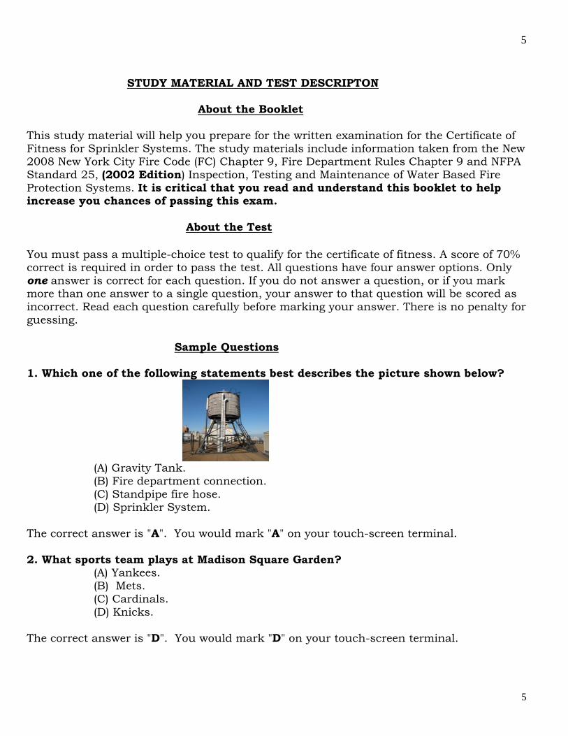
Sample Questions 1. Which one of the following statements best describes the picture shown below?
(A) Gravity Tank. (B) Fire department connection. (C) Standpipe fire hose. (D) Sprinkler System.
The correct answer is "A". You would mark "A" on your touch-screen terminal. 2. What sports team plays at Madison Square Garden?
(A) Yankees. (B) Mets. (C) Cardinals. (D) Knicks.
The correct answer is "D". You would mark "D" on your touch-screen terminal.
6
6
I. INTRODUCTION ______________________________________________________________________________________ A sprinkler system is a fire extinguishing system, other than a water mist system, that utilizes water as the extinguishing agent. Whether a building shall be provided with sprinkler protection or not is generally set forth in the NYC Building Code. The Fire Code however does contain several sprinkler requirements, such as for the high piled combustible storage and for buildings constructed on streets of substandard width. Inspection, testing, servicing and other maintenance of sprinkler systems must be personally supervised (FC901.6.3) and be performed in accordance with NFPA (National Fire Protection Association) Pamphlet #25 2002 edition. All multiple dwellings, factories, office buildings, warehouses, stores and offices, theaters and music halls, and all hospitals and asylums, and all public schools and other public buildings, churches and other places where large numbers of persons are congregated for purposes of worship, instruction or amusement, and all piers, bulkheads, wharves, pier sheds, bulkhead sheds or other waterfront structures shall provide such fire hose, fire extinguishers, buckets, axes, fire hooks, fire doors and other means of preventing and extinguishing fires as the commissioner may direct. Required fire protection systems shall be extended or altered as necessary to maintain and continued protection whenever the building or structure is altered (FC 901.4.1). Systems not complying with this section shall be considered to be impaired. It shall be unlawful to install or maintain any fire protection system or device that has the physical appearance of fire protection equipment but that does not perform a fire protection function where it may be confused with actual fire protection equipment. (FC 901.4.4) An example would be a CCTV camera modeled to look similar to a sprinkler head. Sprinkler and/or standpipe system maintenance and inspections (FC 903.5) 1. Automatic and non-automatic sprinkler systems shall be inspected, tested and maintained as required by NFPA #25 2002 edition by a competent person holding a certificate of fitness, employed by the owner, to see that all parts of the system are in good working order, and that the Fire Department connection or connections, if any, are ready for immediate use by the Fire Department. A detailed record shall be kept of each inspection for examination by any representative of the Fire Department. 2. A supply of at least six extra sprinkler heads shall be kept available on the premises, to replace promptly any fused or damaged sprinklers. Any head which has opened or has been damaged shall be replaced immediately with sprinkler head of similar characteristics such as operating temperature, orifice size, deflector orientation and thermal sensitivity. 3. At least once in five years, the Fire Department connection or connections for a sprinkler system shall be subjected to a hydrostatic pressure test to demonstrate its suitability for Fire Department use. The test shall be arranged to be conducted by a
7
7
Master Fire Suppression Piping Contractor in the presence of a Fire Department representative. The contractor shall be hired by the owner or the owner's representative. 4. There shall be one or more employees with a certificate of fitness to inspect the sprinkler system following the standard of the NFPA 25 of 2002. II. RESPONSIBILITY OF THE BUILDING OWNER_________________________ It shall be the owner’s responsibility to maintain the sprinkler system and to determine the individual qualifications and competencies of the individual his Certificate of Fitness holder to perform certain functions related to inspection, testing and maintenance. 901.6.2 Records. Records of all system inspections, tests, servicing and other maintenance required by this code, the rules or the referenced standards shall be maintained on the premises for a minimum of 3 years and made available for inspection by any department representative. 901.7.1 Impairment coordinator. The building owner shall assign an impairment coordinator to comply with the requirements of this section. In the absence of a specific designee, the owner shall be considered the impairment coordinator. The building owner or their agent shall assign an impairment coordinator to maintain records of all system inspections, tests, servicing and other items of maintenance shall be kept on site for a period of three years and made available for inspection by any member of the FDNY. In absence of a specific designee, the building owner shall be considered the impairment coordinator (FC 901.7.1). III. OUT OF SERVICE SYSTEMS (OOS)____________________________________ Planned removal from service: When the system, or a portion of the sprinkler system, is placed out of service for a scheduled inspection, testing, regular maintenance, minor repairs or for construction affecting not more than 1 floor, the certificate of fitness holder and the impairment coordinator shall be made aware of and authorize the placing of the system out of service. Unplanned out of service condition: A serious defect in the sprinkler system including, but not limited to: an empty tank, a break or major leak in the system’s water piping, inoperative or shut water supply valves, defective fire department connections, construction related shut downs affecting more than one floor, or complete or partial shut downs of the sprinkler system, other than a shut down for a planned removal from service. Fire Department Notifications For Out of Service Conditions:
a) For a planned removal from service, as described above, no notification to the Fire Department is required provided the system will be returned to service within an 8 hour period and when all other fire protection systems in the building (standpipes and alarm systems) are fully operational.

8
8
b) For an unplanned removal from service as described above, the certificate of fitness holder, impairment coordinator, and/or other person responsible for inspecting, maintaining or supervising the operation of a fire protection system shall immediately report such condition to the owner of the building and to the Fire Department Borough Communications office (FC 901.7.5). The telephone numbers are as follows:
Manhattan 212-570-4300 Bronx 718-430-0200 Brooklyn 718-965-8300 Queens 718-476-6200
Staten Island 718-494-4296 c) The initial Fire Department notification shall include the following:
1. A brief description and extent of the out of service condition. 2. The area of the building affected. 3. The type of occupancy 4. The estimated time the system will be out of service. 5. The name and phone number of the person making the notification.
d) When the certificate of fitness holder observes a minor defect or other condition not presenting a serious safety hazard, he or she shall report the defect or condition to the owner, and if the defect or condition is not corrected within 30 days it shall be deemed to be an impairment and reported in writing to the Fire Department (FC 901.7.5). Correspondence should be sent via email [email protected] or by certified documents to:
New York City Fire Department Bureau of Fire Prevention Fire Suppression Unit, 3rd Floor 9 Metro Tech Center Brooklyn, New York 11201
Identifying OOS Systems Using Discs/Tags: Systems that are out of service, both planned and unplanned, shall be immediately identified by placing a tag at each of the following locations: fire department connections, system control valves, fire command center or other clearly visible location in the lobby of the building, indicating which system or part thereof is out of service. Impairment coordinators/building owners shall ensure the placement of these tags by MFSPC’s or MLP (as restricted). In addition, for an unplanned out of service condition, a disc (white or blue) shall be placed at all affected fire department connections to inform responding fire department units of the out of service condition. The impairment coordinator/building owner shall ensure placement of these discs by MFSPC’s, MLP’s (as restricted) or FDNY units. When the condition has been corrected, the disc(s) shall be removed immediately. Tag Requirement: A tag shall be used to indicate that a system, or portion, is out of service (FC901.7.2). A Master Fire Suppression Piping Contractor, Class A or B, or a master plumber (as restricted), shall be required to post tags at the main control valve and
9
9
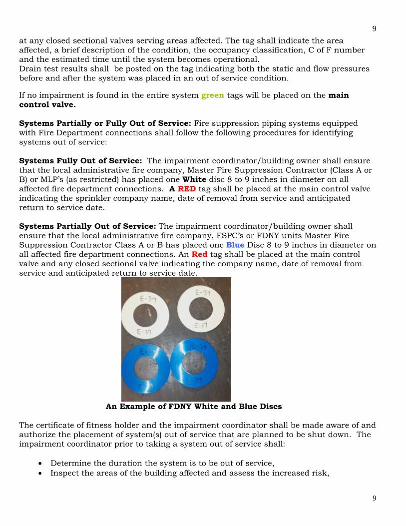
at any closed sectional valves serving areas affected. The tag shall indicate the area affected, a brief description of the condition, the occupancy classification, C of F number and the estimated time until the system becomes operational. Drain test results shall be posted on the tag indicating both the static and flow pressures before and after the system was placed in an out of service condition. If no impairment is found in the entire system green tags will be placed on the main control valve. Systems Partially or Fully Out of Service: Fire suppression piping systems equipped with Fire Department connections shall follow the following procedures for identifying systems out of service: Systems Fully Out of Service: The impairment coordinator/building owner shall ensure that the local administrative fire company, Master Fire Suppression Contractor (Class A or B) or MLP’s (as restricted) has placed one White disc 8 to 9 inches in diameter on all affected fire department connections. A RED tag shall be placed at the main control valve indicating the sprinkler company name, date of removal from service and anticipated return to service date. Systems Partially Out of Service: The impairment coordinator/building owner shall ensure that the local administrative fire company, FSPC’s or FDNY units Master Fire Suppression Contractor Class A or B has placed one Blue Disc 8 to 9 inches in diameter on all affected fire department connections. An Red tag shall be placed at the main control valve and any closed sectional valve indicating the company name, date of removal from service and anticipated return to service date.
An Example of FDNY White and Blue Discs The certificate of fitness holder and the impairment coordinator shall be made aware of and authorize the placement of system(s) out of service that are planned to be shut down. The impairment coordinator prior to taking a system out of service shall:
Determine the duration the system is to be out of service, Inspect the areas of the building affected and assess the increased risk,
10
10
Notify the insurance carrier, the central station operator (if so equipped), the occupants of the affected area, and place out of service tags and discs at the appropriate locations (901.7.4).
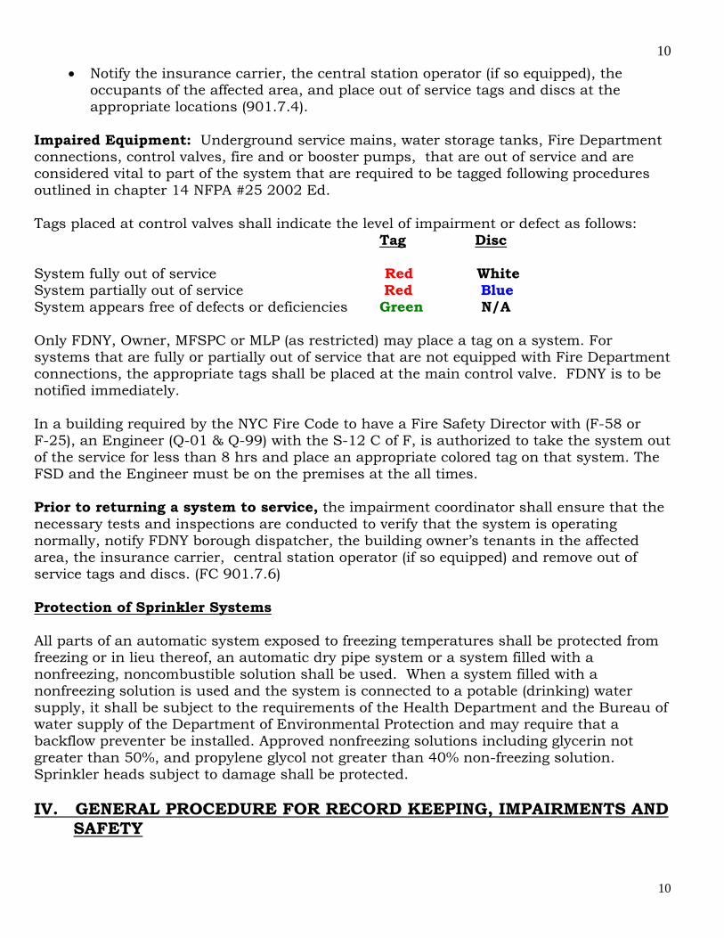
Impaired Equipment: Underground service mains, water storage tanks, Fire Department connections, control valves, fire and or booster pumps, that are out of service and are considered vital to part of the system that are required to be tagged following procedures outlined in chapter 14 NFPA #25 2002 Ed. Tags placed at control valves shall indicate the level of impairment or defect as follows: Tag Disc System fully out of service Red White System partially out of service Red Blue System appears free of defects or deficiencies Green N/A Only FDNY, Owner, MFSPC or MLP (as restricted) may place a tag on a system. For systems that are fully or partially out of service that are not equipped with Fire Department connections, the appropriate tags shall be placed at the main control valve. FDNY is to be notified immediately. In a building required by the NYC Fire Code to have a Fire Safety Director with (F-58 or F-25), an Engineer (Q-01 & Q-99) with the S-12 C of F, is authorized to take the system out of the service for less than 8 hrs and place an appropriate colored tag on that system. The FSD and the Engineer must be on the premises at the all times. Prior to returning a system to service, the impairment coordinator shall ensure that the necessary tests and inspections are conducted to verify that the system is operating normally, notify FDNY borough dispatcher, the building owner’s tenants in the affected area, the insurance carrier, central station operator (if so equipped) and remove out of service tags and discs. (FC 901.7.6) Protection of Sprinkler Systems All parts of an automatic system exposed to freezing temperatures shall be protected from freezing or in lieu thereof, an automatic dry pipe system or a system filled with a nonfreezing, noncombustible solution shall be used. When a system filled with a nonfreezing solution is used and the system is connected to a potable (drinking) water supply, it shall be subject to the requirements of the Health Department and the Bureau of water supply of the Department of Environmental Protection and may require that a backflow preventer be installed. Approved nonfreezing solutions including glycerin not greater than 50%, and propylene glycol not greater than 40% non-freezing solution. Sprinkler heads subject to damage shall be protected. IV. GENERAL PROCEDURE FOR RECORD KEEPING, IMPAIRMENTS AND SAFETY
11
11
It shall be the responsibility of the Certificate of Fitness holder to perform the following: Record keeping - The Certificate of Fitness holder shall maintain a detailed record of all inspections. A record with the date of each inspection, the Certificate of Fitness number, and the signature of the Certificate of Fitness holder shall be posted near the main control valve. A detailed inspection report shall include information relative to conditions of water supply, gravity and pressure tanks and levels therein, valves, risers, piping, sprinkler heads and Fire Department connections, alarms, fire , booster and special service pumps, obstructions, and conditions of all other system equipment and appurtenances. All defects and/or impairments shall be noted on the report. Records shall be readily available to any representative of the Fire Department. These records are to be maintained on site by the building owner for three years. Notification of all defects shall be reported to the owner or their representative by the Certificate of Fitness holder. After 30 days, any of the defects that have not been corrected shall be immediately reported to the Fire Department Borough Communication Office. Failure to make inspections, maintain records, and report defects or violations may be cause for revocation of the Certificate of Fitness and court enforcement proceedings. V. INDIVIDUALS AUTHORIZED TO PERFORM TASKS AS SPECIFIED IN THE NEW YORK CITY FIRE CODE
1. C of F for S-12 -visual inspections only, proper notification and record inspection results for examination by FDNY.
2. C of F holder for S-12* employed by a site-specific building owner with the following certifications: Refrigeration Operating Engineer (Refrigeration Q-99 & Q-01), High Pressure Operating Engineer and NYS High Pressure Operating Engineer are permitted to perform visual inspections, test notification appliances, perform daily and weekly routine maintenance and record all inspection, testing and maintenance results for examination by FDNY.
*(For employees of a single or multiple properties under common ownership employed by the same building owner/management company) 3. Master Fire Suppression Piping Contractor (A or B) (MFSPC) – with S-12 C of F
can inspect, test, maintain and repair/replace all fire standpipe and sprinkler systems components, record maintenance, inspection and test results for examination and evaluation by FDNY.
4. Master Plumber (MP) – with S-12 is limited to residential (R) occupancies 30 sprinkler heads or less without a booster pump.
12
12
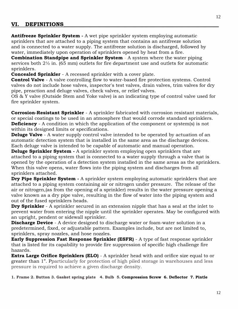
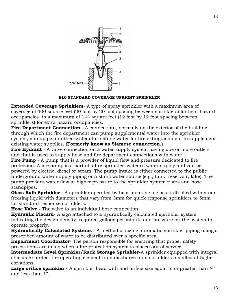
VI. DEFINITIONS_________________________________________________________ Antifreeze Sprinkler System - A wet pipe sprinkler system employing automatic sprinklers that are attached to a piping system that contains an antifreeze solution and is connected to a water supply. The antifreeze solution is discharged, followed by water, immediately upon operation of sprinklers opened by heat from a fire. Combination Standpipe and Sprinkler System - A system where the water piping services both 2½ in. (65 mm) outlets for fire department use and outlets for automatic sprinklers. Concealed Sprinkler - A recessed sprinkler with a cover plate. Control Valve - A valve controlling flow to water-based fire protection systems. Control valves do not include hose valves, inspector's test valves, drain valves, trim valves for dry pipe, preaction and deluge valves, check valves, or relief valves. OS & Y valve (Outside Stem and Yoke valve) is an indicating type of control valve used for fire sprinkler system. Corrosion-Resistant Sprinkler - A sprinkler fabricated with corrosion resistant materials, or special coatings to be used in an atmosphere that would corrode standard sprinklers. Deficiency - A condition in which the application of the component or system(s) is not within its designed limits or specifications. Deluge Valve - A water supply control valve intended to be operated by actuation of an automatic detection system that is installed in the same area as the discharge devices. Each deluge valve is intended to be capable of automatic and manual operation. Deluge Sprinkler System - A sprinkler system employing open sprinklers that are attached to a piping system that is connected to a water supply through a valve that is opened by the operation of a detection system installed in the same areas as the sprinklers. When this valve opens, water flows into the piping system and discharges from all sprinklers attached. Dry Pipe Sprinkler System - A sprinkler system employing automatic sprinklers that are attached to a piping system containing air or nitrogen under pressure. The release of the air or nitrogen,(as from the opening of a sprinkler) results in the water pressure opening a valve known as a dry pipe valve, resulting in the flow of water into the piping system and out of the fused sprinklers heads. Dry Sprinkler - A sprinkler secured in an extension nipple that has a seal at the inlet to prevent water from entering the nipple until the sprinkler operates. May be configured with an upright, pendent or sidewall sprinkler. Discharge Device - A device designed to discharge water or foam-water solution in a predetermined, fixed, or adjustable pattern. Examples include, but are not limited to, sprinklers, spray nozzles, and hose nozzles. Early Suppression Fast Response Sprinkler (ESFR) - A type of fast response sprinkler that is listed for its capability to provide fire suppression of specific high challenge fire hazards. Extra Large Orifice Sprinklers (ELO) - A sprinkler head with and orifice size equal to or greater than 1”. Pparticularly for protection of high piled storage in warehouses and less pressure is required to achieve a given discharge density. 1. Frame 2. Button 3. Gasket spring plate 4. Bulb 5. Compression Screw 6. Deflector 7. Pintle
13
13
EL0 STANDARD COVERAGE UPRIGHT SPRINKLER
Extended Coverage Sprinklers- A type of spray sprinkler with a maximum area of coverage of 400 square feet (20 foot by 20 foot spacing between sprinklers) for light hazard occupancies to a maximum of 144 square feet (12 foot by 12 foot spacing between sprinklers) for extra hazard occupancies. Fire Department Connection - A connection , normally on the exterior of the building, through which the fire department can pump supplemental water into the sprinkler system, standpipe, or other system furnishing water for fire extinguishment to supplement existing water supplies. (Formerly know as Siamese connection.) Fire Hydrant - A valve connection on a water supply system having one or more outlets and that is used to supply hose and fire department connections with water. Fire Pump - A pump that is a provider of liquid flow and pressure dedicated to fire protection. A fire pump is a part of a fire sprinkler system’s water supply and can be powered by electric, diesel or steam. The pump intake is either connected to the public underground water supply piping or a static water source (e.g., tank, reservoir, lake). The pump provides water flow at higher pressure to the sprinkler system risers and hose standpipes. Glass Bulb Sprinkler - A sprinkler operated by heat breaking a glass bulb filled with a non freezing liquid with diameters that vary from 3mm for quick response sprinklers to 5mm for standard response sprinklers. Hose Valve - The valve to an individual hose connection. Hydraulic Placard- A sign attached to a hydraulically calculated sprinkler system indicating the design density, required gallons per minute and pressure for the system to operate properly. Hydraulically Calculated Systems - A method of sizing automatic sprinkler piping using a prescribed amount of water to be distributed over a specific area. Impairment Coordinator- The person responsible for ensuring that proper safety precautions are taken when a fire protection system is placed out of service. Intermediate Level Sprinkler/Rack Storage Sprinkler-A sprinkler equipped with integral shields to protect the operating element from discharge from sprinklers installed at higher elevations. Large orifice sprinkler - A sprinkler head with and orifice size equal to or greater than ¾” and less than 1”.

14
14
Listed Device - A fire protection component that has been tested to perform under parameters specified for its use by a nationally recognized testing agency. Underwriter’s Laboratory (UL) and Factory Mutual (FM) are the two most common. Master Pressure Reducing Valve - A pressure reducing valve installed to regulate pressures in an entire fire protection system and/or standpipe system zone. Main Drain - The primary drain connection located on the system riser and also utilized as a flow test connection. Microbiologically Influenced Corrosion (MIC) - Corrosion caused by the presence of microbes in the water supply that over time attack the interior of metallic piping and cause leaks, pitting, and blockages. Out of service system - A fire protection system that is not fully functional; or whose operation is impaired or is otherwise not in good working order. Old-Style/Conventional Sprinkler- A sprinkler that directs 40% to 60% of the water initially in a downward direction and is designed to be installed with the deflector in either the upright or pendent position. Pendent Sprinkler A sprinkler designed to be installed in such a way that the water stream is directed downward against the deflector. Pintle Screws - A visual indicating device required for sprinklers manufactured prior to 1999 identifying small orifice sprinklers and large orifice sprinklers where orifice size is different than the nominal thread size of the sprinkler head. Pipe Schedule Systems – A method of sizing piping based upon the number of sprinkler heads and the occupancy of the protected area. Preaction Sprinkler System - A sprinkler system employing automatic sprinklers that are attached to a piping system that contains air that may or may not be under pressure, with a supplemental detection system installed in the same areas as the sprinklers. Personal Supervision – Supervision by the holder of a FDNY Certificate of Fitness who is required to personally present on the premises, or other proximate location acceptable to the department, while performing the duties for which the certificate is required. Pressure Control Valve - A pilot operated pressure reducing valve that may be used with a fire or booster pump designed for the purpose of preventing the incoming water supply pressure from dropping below a set pressure. Pressure-Reducing Valve - A valve designed for the purpose of reducing the downstream water pressure under both flowing (residual) and nonflowing (static) conditions. Pressure Relief Valve – A valve designed for the purpose of releasing excess air or water pressure from the Fire Protection Piping System. Pressure Tank - A tank using air pressure to supplying water for water-based fire protection systems. Tank contents to be maintained at one third air to two thirds water. Quick Response Sprinkler Head- A sprinkler having a fusible link with a response time index (RTI) of 50 or less. Recessed Sprinkler - A sprinkler in which all or part of the body, other than the shank thread, is mounted above the ceiling. Residential Sprinkler - A type of fast response sprinkler that has been specifically tested to enhance survivability in the room of fire origin and listed for use in dwelling units. Response Time Index (RTI) – A measurement of the thermal sensitivity of a sprinkler head expressed in (meters-seconds) 1/2. Sprinkler Identification Number (SIN) - Sprinklers manufactured after Jan. 1, 2000 are required to be marked to identify performance characteristics.
15
15
Supervisory signal – A signal indicating the need for action in connection with the supervision of guard tours, fire extinguishing systems or equipment, fire alarm systems or the maintenance features of related systems. Sidewall Sprinkler- A sprinkler having special deflectors that are designed to discharge most of the water away from the nearby wall. Small orifice sprinklers - A sprinkler head with and orifice size smaller than ½”. Solder Link Sprinkler A sprinkler operated by the melting of a metal link, they vary in size and configuration for quick response and standard response sprinklers. The smaller the size of the link, the faster the sprinkler operates. Spray Sprinkler- A type of sprinkler listed for its capability to provide fire control for a wide range of fire hazards. The most commonly used sprinkler since 1953. Sprinkler system - A fire extinguishing system, other than a mist fire extinguishing system that utilizes water as the extinguishing agent. Standard Response Sprinkler Head - A sprinkler having a fusible link with a response time index (RTI) of 80 or more. Supervisory signal-initiating device - An initiating device, such as a valve supervisory switch, water level indicator, or low-air pressure switch on a dry-pipe or pre-action sprinkler system, that triggers a supervisory signal. Testing - A procedure used to determine the status of a system as intended by conducting periodic physical checks on water based fire protection systems such as waterflow tests, fire pump tests, alarm tests, and trip tests of dry pipe, deluge, or preaction valves. These tests follow up on the original acceptance test at intervals specified in the appropriate chapter of NFPA #25, 2002 edition. Upright Sprinkler - A sprinkler designed to be installed in such a way that the water spray is directed upwards against the deflector. Water Spray - Water in a form having a predetermined pattern, particle size, velocity, and density discharge from specially designed nozzles or devices. Water Supply - A source of water that provides the flows [gal/min (L/min)] and pressures [psi (bar)] required by the water-based fire protection system. Wet Pipe Sprinkler System - A sprinkler system employing automatic sprinklers attached to a piping system containing water and connected to a water supply so that water discharges immediately from sprinklers opened by heat from a fire. Water Spray Fixed System - A special fixed pipe system connected to a reliable fire protection water supply and equipped with water spray nozzles for specific water discharge and distribution over the surface or area to be protected. The piping system is connected to the water supply through an automatically or manually actuated valve that initiates the flow of water. An automatic valve is actuated by operation of automatic detection or manual release equipment installed in the same areas as the water spray nozzles. (In special cases, the automatic detection system may also be located in another area.) Water Tank - A tank supplying water for water-based fire protection systems. VII. SYSTEM TYPES_____________________________________________________ AUTOMATIC WET SPRINKLER SYSTEMS Automatic sprinkler systems are designed to automatically distribute water on a fire. The sprinkler system is designed to extinguish the fire entirely, or to prevent the spread of the

16
16
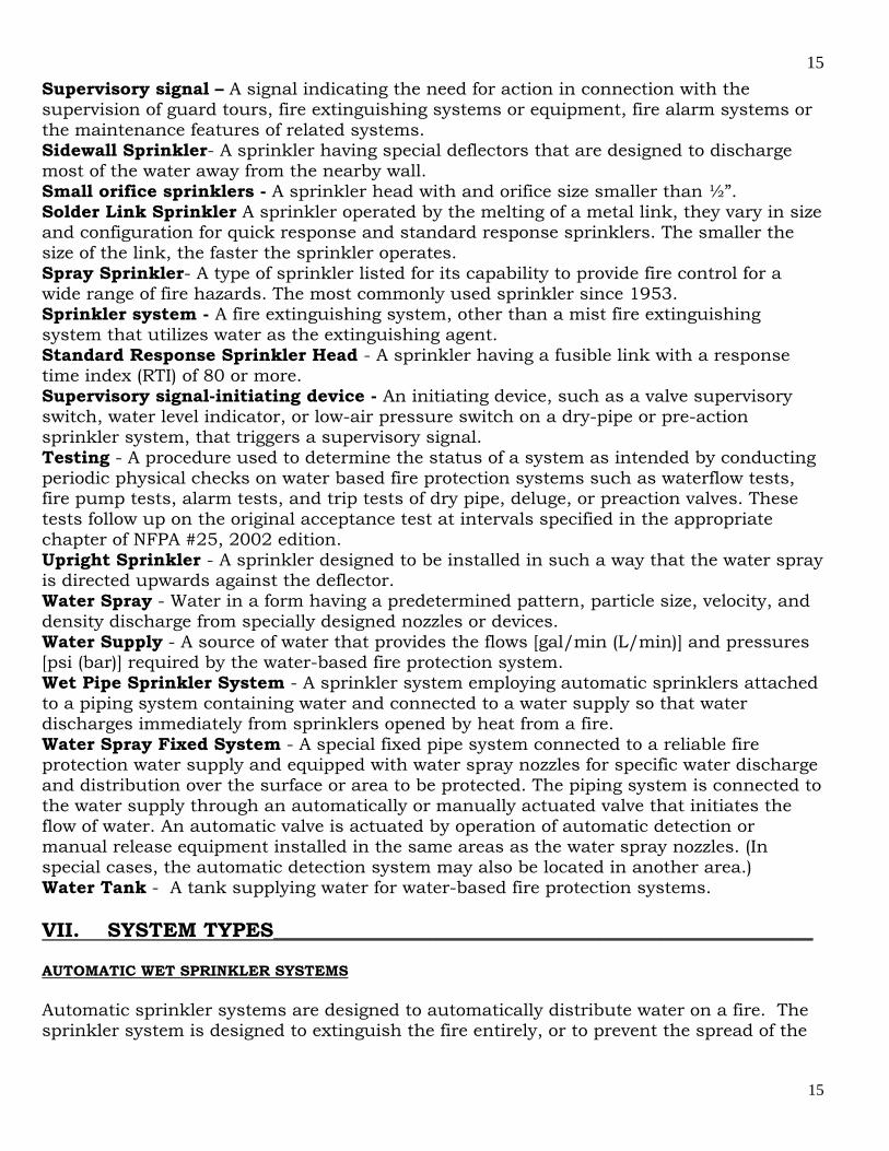
fire. An automatic sprinkler system consists of a series of pipes at or near the ceiling in a building. The sprinkler system is fitted with automatic devices designed to release water on a fire. These devices are called sprinkler heads. The sprinkler heads are normally closed by a disc or cap. This cap is held in place by a heat sensitive releasing element. A rise in temperature to a predetermined level causes the sprinkler head to open. Water is then discharged in the form of spray. When the sprinkler heads open they are said to have fused. The sprinkler heads are fitted at standard intervals on the piping. If more than one head opens, the area sprayed by each overlaps that of the sprinkler head next to it. Sprinkler systems are required by law in various occupancies. They also may be installed voluntarily by the owner of the building. The sprinklers are installed to protect the building and its residents. The installation of sprinklers has a major effect in reducing fire losses. About 96% of the fires are extinguished or controlled when sprinklers are installed. The 4% failure was due to a variety of causes including defective piping, closed supply valves, frozen water lines, improper maintenance, and blocked water supply piping. Automatic sprinklers are very effective for life safety. They signal the existence of a fire. At the same time they discharge water to the burning area. When sprinklers are installed there are rarely problems getting water to the seat of the fire. They also reduce interference with visibility for fire fighting due to smoke. The downward force of the water sprayed from sprinklers lowers the smoke level in the room. The sprinklers also serve to cool the smoke. This makes it possible for persons to remain in the area much longer than they could if the room were without sprinklers. Most standard sprinkler systems have devices that automatically sound an alarm when a sprinkler head discharges water. This alarm is usually an audible signal in the building. In many cases they also give an alarm at a remote location, such as an approved central station company. The central station company monitors the entire fire protection system for water discharge and problems with the equipment. When water discharge or equipment problems are identified the local fire house is immediately notified. This allows the Fire Department to gain control of a fire as quickly as possible. Water is rarely discharged accidentally from sprinkler heads. The most commonly installed system is wet pipe systems which have water in the piping at all times. This type of system is used where the temperature is maintained at minimum of 40F to prevent the system from freezing. A picture of a typical wet pipe system is shown in the picture below:
17
17
A typical wet pipe system Where temperatures drop below freezing the ordinary wet pipe system cannot be used. There are two methods for using automatic sprinklers in places exposed to freezing temperatures. One method is a system where water enters the sprinkler piping only after a control valve is opened. These are dry pipe systems, deluge systems, or preaction systems. The other method adds an antifreeze solution to the water in the wet pipe system. The antifreeze solution is a mixture of chemicals designed to prevent the water from freezing. Antifreeze Solutions - Antifreeze is added to the water in piping exposed to freezing temperatures. When the sprinkler heads fuse the system works in the same way as a wet pipe system. Antifreeze solutions are costly and may be difficult to maintain. Antifreeze is usually used for small unheated areas. Antifreeze solutions may be used only in accordance with applicable local health regulations. Existing Cold Weather Valves - An automatic sprinkler system should not be shut off and drained to avoid freezing during cold weather. However, parts of the sprinkler system may be shut down. Permission must be obtained from the local fire house. Permission may be given to shut off a maximum of 10 sprinkler heads on a wet pipe system. These shutoff valves are commonly referred to as cold weather valves. These valves are no longer permitted to be installed. AUTOMATIC DRY SPRINKLER SYSTEMS Dry Pipe Sprinkler Systems are installed where a wet pipe system cannot be heated to prevent freezing. Under normal conditions there is no water in the piping. Instead the piping in the system is filled with air or nitrogen under pressure. The air pressure in the piping is controlled automatically by an air maintenance device. The system uses standard sprinkler heads. When a sprinkler head is opened by the heat from a fire, the air pressure is reduced in the piping. The drop in air pressure causes a special dry pipe valve to open. A supervisory device signals when the valve is opened. Then water flows into the piping and out of the opened sprinklers. This water flow also sounds a local alarm to alert the

18
18
people in the building of the fire. The alarm may also be transmitted to a central station company. This station will then notify the Fire Department that there is a fire. In buildings where life hazard is very high (e.g., schools, hospitals) the alarm is transmitted directly to the Fire Department. Sometimes a combination of a wet pipe and a dry pipe system may be used when part of the building cannot be heated. A typical dry pipe system
Dry Pipe Valve Designs - These valves prevent water from flowing into the piping until a sprinkler head has opened. The air pressure in the system keeps the clapper closed. This clapper prevents the water from flowing into the system. When the sprinkler head opens it causes a drop of pressure in the piping. This causes the valve to open and allows water into system. Most dry pipe valves are designed so that a moderate air pressure in a dry pipe system will hold back a much greater water pressure. When the clapper has opened the valve is said to have tripped. A picture of a typical dry pipe valve is shown below:
A Typical Clapper Type Dry Valve

19
19
Higher than normal water pressure, a water hammer, may cause the dry valve to trip by accident. Water hammer is caused by a sudden flow of water or a sudden change of water pressure in the system. To reduce this danger air pressure is usually kept well above the normal trip point. The air pressure is usually set at 15 to 20 psi (pounds per square inch) above the normal trip level. Some valves are specially designed for low pressures. In all cases the manufacturer's instructions regarding pressures to be maintained shall be followed. Quick Opening Devices - In a dry pipe system there is a delay between the opening of a sprinkler and the discharge of water. This delay may allow the fire to spread and more sprinkler heads to open. The delay is due to the time required for the air leave the sprinkler piping. This difficulty may be partly overcome by the installation of quick opening devices. Two devices are used to reduce the time needed to open the clapper and allow water into the system. These devices are an accelerator and an exhauster. They are both automatically activated when a drop of 2 psi in air pressure is detected in the system. They quickly change the water and air pressure balance in the system. This change trips the dry pipe valve allowing the water to force its way through the sprinkler piping in less time. The failure of an accelerator or exhauster to operate will increase the normal tripping of a dry pipe valve.
PREACTION SPRINKLER SYSTEMS Preaction systems are designed for situations where there is danger of serious water damage. Water damage is usually caused by damaged sprinklers or broken piping. Under normal conditions there is no water in the piping. The air in the piping may or may not be is under pressure. A preaction valve prevents the water from entering the system. The valve is automatically opened when a fire detection system discovers that there is a fire or smoke condition. The preaction valve is tripped by the fire detection system before any of the sprinkler heads open. A supervisory device signals when the valve is opened. The preaction valve can also be operated manually. The preaction system has several advantages over a dry pipe system. The preaction valve opens sooner because the fire detectors react to heat changes faster than sprinkler heads. Fire and water damage may be decreased because water is sprayed on the fire more quickly the alarm signal is given as soon as the preaction valve is opened. Heat responsive devices are commonly used to trip preaction valves. These devices are also used to activate alarm and supervisory systems. There are three main devices used to trip preaction valves: 1) devices designed to operate at a fixed temperature; 2) devices designed to operate when the temperature in the room increases a set amount in a given time period (rate-of-rise), and 3) devices combining fixed temperature and rate of rise devices. Other ways to activate a preaction valve are smoke detectors, gas detecting systems, hydraulic, electric, manual release, and automatic signals from other safety systems.
20
20
Alarms are standard accessory equipment on water control valves. They provide an audible signal in the building if the valve operates for any reason. An alarm is also sent out if a problem is discovered with the equipment. The alarms send a signal to central station company or a public fire alarm system. Often the signal is sent to both the central station company and the public alarm. Preaction System with a Recycling Feature - A special kind of preaction system is a recycling system for controlling sprinklers. This system shuts off the water when the fire has been put out or the heat drops. If the fire rekindles or the heat rises sharply, water is discharged again. The system continues cycling on and off as long as the fire persists. Combined Dry Pipe and Preaction Systems - These systems have the basic features of both types of systems. The piping system contains air under pressure. A heat detecting device opens the water control valve and a quick opening device. The system then fills with water and operates as a wet pipe system. If the heat detecting system fails, the system will operate as a standard dry pipe system.
DELUGE SPRINKLER SYSTEMS A deluge sprinkler system is equipped with open sprinkler heads designed to wet down an entire area involved in a fire. This system is needed when there is danger of a fire rapidly spreading throughout the building. The deluge system will slow down the spread of the fire. Deluge systems are suitable for hazardous occupancies. This includes buildings in which flammable liquids or other hazardous materials are handled or stored. The sprinkler heads in the deluge system are open at all times. Under normal conditions there is no water in the piping. The air in the piping is not under pressure. A closed control valve prevents water from flowing into the system. A fire detection device automatically opens the control valve when a fire is identified. A supervisory device signals when the valve is opened. When the valve is opened water flows into the system. The water is then discharged out all of the sprinkler heads. The water control valve may also be opened manually.
NON-AUTOMATIC DRY SPRINKLER SYSTEMS In this type of system all pipes are normally dry. Water is supplied when needed by pumping water into the system through the Fire Department connection. Some of these systems are supplied by manual operation of a water control valve and may be equipped with sprinklers with or without fusible links. There are several non-automatic systems: 1) Perforated pipe systems - a single line of piping drilled at intervals for water discharge. These systems are usually found in basements or other areas difficult to reach in fire fighting operations. 2) Open fixed spray nozzles for transformer vaults or other hazardous areas; 3) exterior exposure sprinklers (or window sprinklers) use open sprinkler heads to form an external water curtain on the walls of a building, and 4) Foam supply systems are used for the protection of special hazardous occupancies.
21
21
GARBAGE COMPACTOR SPRINKLER SYSTEMS Waste compactors are usually found in tall multiple dwelling complexes such as apartment buildings. They are used to reduce the trash buildup in a building. They consist of a tall chute with an opening at each floor. These opening are used for trash disposal. Occupants of the buildings take their trash and throw it through the opening and down the chute. The trash piles up at the bottom of the chute where a device regularly crushes the trash into smaller blocks of trash. The blocks of trash are then removed and taken to a garbage dump. The compactor may be located indoors or outdoors. The build-up of trash in the compactor chute is a fire hazard. Fires may be started in several ways, for example, by a smoldering cigarette thrown into the compactor chute. Sprinkler systems must be installed to put out fires that start in the compactor chute. Any of the standard water supply sources may be used to supply the compactor sprinkler system. For example, gravity tanks, fire pumps and pressure tanks are all used as water supply sources. Fire doors shall be installed in the chute to allow firefighter access to burning trash. The Certificate of Fitness holder shall know the location of all sprinkler heads, control valves, supply lines and compactor rooms. A sketch of the entire compactor sprinkler system shall be drawn by the Certificate of Fitness holder. This sketch shall be posted in the compactor room in a frame under glass. The sketch shall be made available to any representatives from the Fire Department. The Certificate of Fitness holder may be questioned about this sketch by inspectors from the Fire Department inspectors during routine inspections. A sign indicating the location of all control valves shall be kept in the compactor room. This sign is shall be displayed with the sketch in the compactor room. All control valves in the sprinkler system shall be labeled. The label is to show the purpose of the valve. Additionally, the labels shall be attached to the yoke of the valves. All indicating valves in the compactor sprinkler system shall be sealed open. A minimum of 6 extra sprinkler heads with the appropriate wrenches shall be available to replace any opened or damaged sprinkler heads. Opened or damaged sprinkler heads shall be replaced immediately. A garden hose connected to a water supply shall be kept in the compactor room. This hose may be used to put out small fires or smoldering material in the compactor room. The Certificate of Fitness holder shall conduct an inspection of the entire sprinkler system at least once a month. Special attention should be given to the condition of the sprinkler heads in the compactor chute and the compactor room. Any defects or violations shall be recorded in a detailed inspection report. All inspections are recorded on a card that shall be kept near the main control valve. The Certificate of Fitness holder shall sign and date the card each time an inspection is made. If any minor defects in the system are discovered they shall be reported to the owner of the building. If repairs are not made within 30 days the Certificate of Fitness Holder must notify the Bureau of Fire Prevention. If any major defects are discovered they shall be reported to the FDNY Dispatcher, the owner of the building, and the Bureau of Fire Prevention. Major defects shall be repaired immediately.
22
22
When a fire is discovered in the compactor the Certificate of Fitness holder should notify the local fire house immediately. He/she should not attempt to enter the compactor chute to put out the fire.
VIII. WATER SUPPLIES FOR SPRINKLER SYSTEMS The sources used to supply water to sprinkler systems are the same as those for standpipe systems. Sprinklers may be supplied from one or a combination of sources. For example, they may be supplied by public mains, gravity tanks, pressure tanks, fire pumps, reservoirs, rivers, or lakes. A single water supply would appear to be all that is needed to supply a sprinkler fire protection system. This assumes that there is enough water at an acceptable pressure. However, a single supply may be out of service (for maintenance or repair) during a fire emergency or it may be disabled during fire or before the fire is fully extinguished. Additionally, the water supply may fall below normal pressure or volume during an emergency. These are just a few reasons why it is good to have a secondary water supply. In some cases it is required by law to have a secondary water supply source. Whether a second source is needed depends on several factors. These factors include the strength and reliability of the primary supply, the value of the property, the height, area, occupancy classification and design of the building. When a sprinkler system is supplied from a public water main, the entire system shall be shut down by closing a non-indicating type control valve. This valve is located between the building and the water main in a box that is recessed into the sidewalk. The location of the box is found by reading a sign on the building or on a post nearby. The sign might read “Shutoff for Sprinkler System Located 6 Feet from This Sign’’, or it may have similar instructions. A special key will be required to operate this valve. Curb Valves - Gate valves of the non-indicating type are provided in water distribution systems. Gate valves allow the sprinkler system to be shut off for repairs or maintenance. Such valves are normally a non-rising stem type. They are operated using a special key wrench. A valve box is located over the valve to keep dirt from the valve. The valve box also provides a convenient access point for the valve wrench to the valve nut. A complete record should be made for each valve in the system. This record should include the exact location, the date it was installed, the make, the direction of opening, number of turns to open, and any maintenance that was performed. The control valve for the building may also be on the outside wall or attached to an upright post, known as a post indicator valve (PIV). The building or section of the building controlled by the valve is usually marked on the post. The position of this valve (open or closed) is shown through a telltale opening in the post. On some posts, a padlock must first be opened to release the operating wrench or wheel handle.

23
23
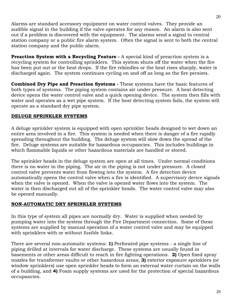
The main water supply for sprinklers may also be controlled by an OS&Y valve (Outside Stem and Yolk valve). The valves are found just inside the building wall on the main riser, or outside in protected pits. It is easy to tell at a glance if the valve is open or shut. When the stem is all the way out the valve is open. When the stem is all the way in the valve is closed. Approved Indicator Valves use a flag that shows the valve position and the valves commonly are used to control the water supply for individual floors in a building. Indication Control valves are also installed to shut off certain sections of an individual floor. Being able to shutoff parts of a building allows the Fire Department to have greater control over the sprinkler system. When a fire is under control in an area the OS&Y valve can be closed to prevent any further water damage. Sometimes repairs must be made to the sprinkler system. When this occurs the indicating control valves are used to close the water supply to only those sections being repaired. This is good safeguard since the rest of the sprinkler system does not have to be shut down. Pumper Connections for Fire Department Use: Normally a sprinkler system is connected to an automatic water supply source. Auxiliary sources of water are supplied through Fire Department connections at the building. Fire Department connections are a standard part of most sprinkler systems. When responding to an alarm most Fire Departments supply water to the standpipe system first. The standpipe system supplies water to the fire hoses to be used within the building. Water is then supplied to the sprinkler system through its own Fire Department connection. Care should be taken that standpipe and the sprinkler connections are properly marked because the connections look the same. The exact purpose of each Fire Department connection should be shown nearby or on the Fire Department connection itself. The New York City Building Code requires Fire Department Connection to be color coded. The Fire Department connection to an automatic sprinkler system shall be painted green. The Fire Department connection to non-automatic sprinkler system shall be painted Silver. The Fire Department connection to a standpipe system shall be painted red. Local Law 58/2009 requires color coding of fire standpipe and fire sprinkler systems to have the risers, cross connections to the water supply piping painted red. The Fire Department connection to a combined standpipe/sprinkler system shall be painted yellow. Fire Department connections must always be accessible. Each connection shall be fitted with a lower check valve. The lower check valve prevents the backflow of the private water supply into the Fire Department connection. The figure below shows the main features of a Fire Department connection.
24
24
Fire Department connection The automatic ball drip device between the lower check valve and the outside Fire Department water from building up in the piping and shall be installed in the horizontal position. This ball drip device makes sure that the Fire Department connection is not blocked by water which has frozen within the piping. If water freezes in the piping, the Fire Department will not be able to pump water into the system. Gravity Tanks: Gravity tanks of adequate capacity and elevation make a good primary supply and may be acceptable as a single supply. A gravity tank may be located on the top of a building or on a tall tower. The water in the tank is distributed throughout the sprinkler system because of the pull of gravity. Pressure Tanks: Pressure tanks have several possible uses in automatic sprinkler fire protection systems. The tank is normally kept at two-thirds full of water and one third full of air. The air pressure in the tank shall be maintained at or above 75 psi. Air for pressure tanks is supplied by air compressors. Because the water is always under pressure it can be forcefully distributed throughout the sprinkler system. An important limitation is the small amount of water that can be stored in such tanks. Where a small pressure tank is accepted as the water supply, the system is called a Limited Supply System. Pressure tanks are often used in situations where an adequate amount of water can be supplied by a public or private source but the water pressure is not adequate. The pressure tank gives a strong starting pressure for the first sprinklers that open. The flow from the tank may be used while the automatic fire pumps begin to increase the water supply pressure. Pressure tanks are often used in tall buildings that need extra water pressure to supply the highest line of sprinkler heads. The pressure tank supplies these sprinkler heads until the Fire Department begins pumping water into the sprinkler system. Fire Pumps: Fire pumps can be used as a main water supply source for sprinkler systems. They may also be used in combination with gravity tanks to supply sprinkler system. Fire pumps are designed to take the water from a supply source and then discharge the water into the fire protection system under pressure. The amount of pressure with which the water is discharged from the pump is called the total head. The total head is measured in pounds per square inch (psi). The higher the psi rating of the pump the greater the
25
25
pressure with which the water can be discharged. Fire Pumps shall be sized to satisfy the hydraulic requirements of the sprinkler system. A fire pump having both a reliable source of power and a reliable suction water supply is an effective piece of equipment. A suction water supply is simply a body of water that the pump can draw water from. Fire pumps are commonly used because they can pump water into the sprinkler system under high pressure. With a good water supply a fire pump can pump water into a sprinkler system for a long time. Manually started pumps may be used as a secondary supply source if the primary water supply will last long enough to allow the pump to be started. This type of system gives an automatic waterflow signal to the Certificate of Fitness holder when the pump must be started. Automatic fire pumps are usually needed where a high water demand may occur immediately. This demand may occur in a deluge system. The automatic fire pump is also used when someone is not always present to activate a manual pump. Automatic fire pumps must have their suction “under a positive head” to avoid the delays of drawing water from a supply source. Under positive head simply means that the water supplying the pump must be fed into the fire pump under pressure. This can be achieved by connecting the fire pump to a suction tank. Water is forced into the pump because of gravity. IX. WATER-FLOW ALARMS AND SPRINKLER SYSTEM SUPERVISION Sprinkler systems should have devices and equipment for signaling when water flow through risers or mains supplying the systems. The flow may be due to fire, leakage, or accidental rupture of the piping. It is important that prompt action is taken when waterflow is signaled by these devices. Functions of Alarms and Supervisory Signals - A sprinkler system with a water alarm serves two functions: 1) It is an effective fire extinguishing system, and 2) It is an automatic fire alarm. An alarm is signaled as soon as a sprinkler head has opened. This is important since it allows the occupants’ time to leave the building. It also signals that the Fire Department should be summoned. Waterflow alarms and fire alarms give warning of the actual occurrence of a fire. They also signal when water flows through the system due to broken pipes. Alarms alert occupants and summon the Fire Department. Any signal, whether waterflow or supervisory, may be used to sound an audible local sprinkler alarm. It may also send a signal to the central station company. The central station company will then contact the local fire house. Supervisory devices are often connected to an approved central station company which monitors the sprinkler system for problems with equipment and when sprinkler heads are opened. The central station company should be notified when any control valves are closed for maintenance or repair. This reduces the number of false alarms.
26
26
Sprinkler systems are required to have an approved water motor gong or an electric bell, horn, or siren on the outside of the building. An electric bell or other audible signal device may also be located inside the building. Water operated devices must be located near the alarm valve, dry pipe valve, or other water control valves in order to avoid long runs of connecting pipe. Devices and Equipment Supervised. Sprinkler system supervision is commonly provided for several purposes. They are used to supervise 1) water supply control valves, 2) low water level in water supply tanks, 3) low temperature in water supply tanks or ground level reservoirs, 4) high or low water level in pressure tanks, 5) high or low air pressure in pressure tanks, 6) high or low air pressure in dry pipe sprinkler systems, 7) failure of electric power supply to fire pumps and, 8) automatic operation of electric fire pumps. Waterflow Alarm Valves - The basic design of most water-flow alarm valves is that of a check valve which lifts from its seat when water flows into a sprinkler system. This alarm then starts an audible signal to alert the occupants in the building that the sprinkler system has been activated. Vane type waterflow - Switches have a paddle inserted inside the main supply piping perpendicular to the direction of flow. Upon waterflow, the paddle switch transmits an alarm. Vane type waterflow switches cannot be installed to monitor waterflow in dry pipe sprinkler systems. Alarm Retarding Devices – An alarm check valve that is exposed to changing water supply pressure needs an alarm retarding device. This is required to prevent false alarms when the check valve clapper is lifted from its seat by a temporary pressure surge. Vane type water flow switches sensitivity can also be adjusted to changing water pressures. X. SYSTEM COMPONENTS______________________________________________
SPRINKLER HEADS Sprinkler heads are made of metal. They are screwed into the piping at standard intervals. The water is prevented from leaving the sprinkler head by an arrangement of levers and links. The levers and links are soldered together on the sprinkler head. The solder is a metal alloy with a fixed melting point. Other types of sprinkler heads use a glass bulb which expands and breaks under heat. The sprinkler head is factory tested to withstand at least 400 psi without injury or leakage. If properly installed, there is little danger of the sprinkler operating unless it is damaged. There are over 50,000 different variations of sprinkler heads. Sprinklers manufactured after 1/1/2000 are required to have a Sprinkler Identification Number (SIN). Sprinkler heads manufactured prior shall be replaced as required with sprinkler heads of similar characteristics such as orifice size, temperature rating, and deflector orientation. A sprinkler head that has been recalled is called the "cycling sprinkler". This sprinkler cycles water on and off depending on the temperature. When the disc reaches a temperature of 165ºF, the valve opens, permitting water to flow. When the disc
27
27
temperature cools the valve closes to shut off the water. These sprinklers and all other sprinklers listed for recall at www.cpsc.gov are subject to replacement. Recalled sprinkler heads
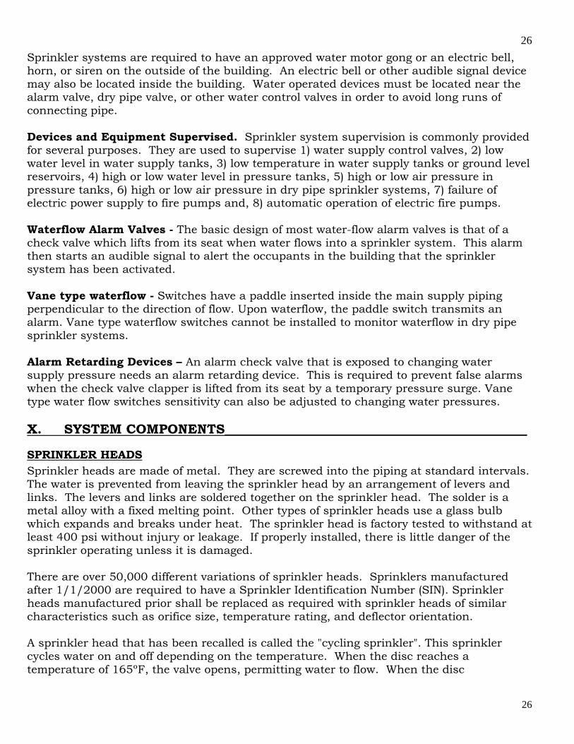
Some sprinkler heads are designed to be used in special situations. Sprinkler heads exposed to corrosive conditions are often covered with a protective coat of wax, or lead. Corrosive vapors are likely to make automatic sprinklers inoperative or slow down the speed of operation. They can also seriously block the spray nozzles in the sprinkler heads. They can damage, weaken or destroy the delicate parts of the sprinkler heads. In most cases such corrosive action takes place over a long time. For this reason the sprinkler heads must be carefully watched for signs of corrosion. Care should be taken to make sure that the protective coating is not damaged when handling or replacing the heads. A typical fusible link type sprinkler head is shown in the picture below.
A Typical Sprinkler Head
Spray Pattern of Sprinkler Heads - The best way to put out a fire is to spray the water from the sprinkler head downward and horizontally. The spray pattern will also prevent the spread of the fire. The force of the water against the deflector creates a heavy spray which is directed outward and downward. The shape of the deflector determines the spray pattern of the water discharged from the sprinkler head. Usually, this is an umbrella shaped spray pattern. At a distance of 4 feet below the deflector, the spray covers a circular area having a diameter of approximately 16 feet when the sprinkler is discharging 15 gpm. Sprinkler Spray patterns must not be obstructed by building components or storage.
28
28
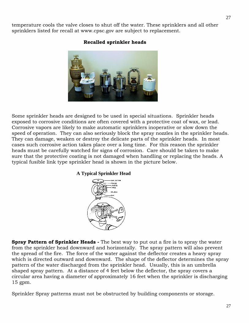
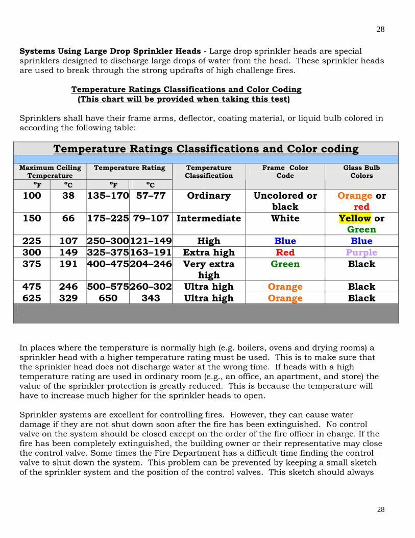
Systems Using Large Drop Sprinkler Heads - Large drop sprinkler heads are special sprinklers designed to discharge large drops of water from the head. These sprinkler heads are used to break through the strong updrafts of high challenge fires. Temperature Ratings Classifications and Color Coding (This chart will be provided when taking this test) Sprinklers shall have their frame arms, deflector, coating material, or liquid bulb colored in according the following table:
Temperature Ratings Classifications and Color coding
Maximum Ceiling Temperature
Temperature Rating
ºF ºC ºF ºC
Temperature Classification
Frame Color Code
Glass Bulb Colors
100 38 135–170 57–77 Ordinary Uncolored or black
Orange or red
150 66 175–225 79–107 Intermediate White Yellow or Green
225 107 250–300 121–149 High Blue Blue 300 149 325–375 163–191 Extra high Red Purple 375 191 400–475 204–246 Very extra
high Green Black
475 246 500–575 260–302 Ultra high Orange Black 625 329 650 343 Ultra high Orange Black
In places where the temperature is normally high (e.g. boilers, ovens and drying rooms) a sprinkler head with a higher temperature rating must be used. This is to make sure that the sprinkler head does not discharge water at the wrong time. If heads with a high temperature rating are used in ordinary room (e.g., an office, an apartment, and store) the value of the sprinkler protection is greatly reduced. This is because the temperature will have to increase much higher for the sprinkler heads to open. Sprinkler systems are excellent for controlling fires. However, they can cause water damage if they are not shut down soon after the fire has been extinguished. No control valve on the system should be closed except on the order of the fire officer in charge. If the fire has been completely extinguished, the building owner or their representative may close the control valve. Some times the Fire Department has a difficult time finding the control valve to shut down the system. This problem can be prevented by keeping a small sketch of the sprinkler system and the position of the control valves. This sketch should always
29
29
be readily available. This sketch is very helpful to the firefighters when they have to work with the sprinkler system. Build-up of Foreign Material on Sprinklers - Sometimes conditions exists which cause a build-up of foreign material on sprinkler heads. This may prevent the sprinkler head from working properly. This build-up is commonly called loading. The build-up of foreign material insulates the sprinkler head. This build-up prevents the sprinkler from opening at the desired temperature. If the build-up is hard, it may prevent the sprinkler from opening. Replace loaded sprinkler heads with new sprinkler heads rather than attempting to clean them. If the deposits are hard, attempts to clean the heads are likely to damage them. This damage may prevent the sprinkler heads from working properly. The damage may also cause the sprinkler head to leak. Deposits of light dust are less serious than hard deposits. Dust build-up may delay the operation of sprinkler heads. However, it will not prevent the eventual discharge of water. Dust deposits can be blown or brushed off. If a brush is used, it should be soft to avoid possible injury to sprinkler parts. Scouring or acidic liquids are likely to damage the sprinkler heads and should not be used for cleaning. Hot solutions of any kind should never be used to clean the sprinkler heads. Removal of protective caps and straps on glass bulb sprinklers shall be performed at the time of installation. Spare Sprinkler Heads Sprinklers required for emergency replacement must be representative of the type of sprinklers installed along with the proper wrenches. These wrenches shall be provided in the spare head cabinet. It is critical sprinklers be replaced with devices that will perform similarly to the original system sprinklers. Sprinklers that are replaced during an emergency by unlicensed individuals require that the devices used have been verified appropriate for the protected area by a Master Fire Suppression Piping Contractor. After activation by fire, sprinklers in close proximity to the affected heads is must always recommended be replaced. A stock of spare sprinklers (not less than 6) shall be kept on the premise where the temperature does not exceed 100 Degrees F and shall include all types and ratings installed in the protected facility and provided as follows:
Under 300 sprinklers six. 301 - 1000 sprinklers twelve. Over 1000 sprinklers twenty four.
PRESSURE TANKS Pressure tanks are enclosed water tanks of limited size. Air pressure in the tank permits forceful discharge of water in the tank into the sprinkler system. A pressure tank may be

30
30
used as a primary or secondary water supply for a sprinkler system. A pressure tank is usually housed in an enclosed structure. The temperature in the enclosure is kept at 40˚ Fahrenheit or above. The heated structure may be located anywhere in the side or even outside of the building. Pressure tanks are to be maintained at approximately two-thirds full of water and one-third full of pressurized air. The minimum acceptable air pressure inside the tank is 75 psi (pounds per square inch). The air pressure in the tank is automatically maintained by an air compressor. The maximum gross capacity of pressure tanks is 9,000 gallons. Some sprinklers systems require more than 6,000 gallons of water. When this occurs several pressure tanks are used in combination to supply the system. A standard pressure tank is shown in the sectional diagram below:
Standard Pressure Tank Pressure Tank Alarms - All pressure tanks used to provide the required primary water supply for a sprinkler system shall be equipped with two high and low alarm systems. One system monitors the high and low air pressure. The other system monitors the high and low water levels. The alarm system automatically monitors the air-to-water volume ratio which should always be 1 (air) to 2 (water). An alarm signals the Certificate of Fitness holder or Central Station operator when the water level or the air pressure falls too high or too low. When this occur the pressure tanks should be adjusted or repaired immediately.

31
31
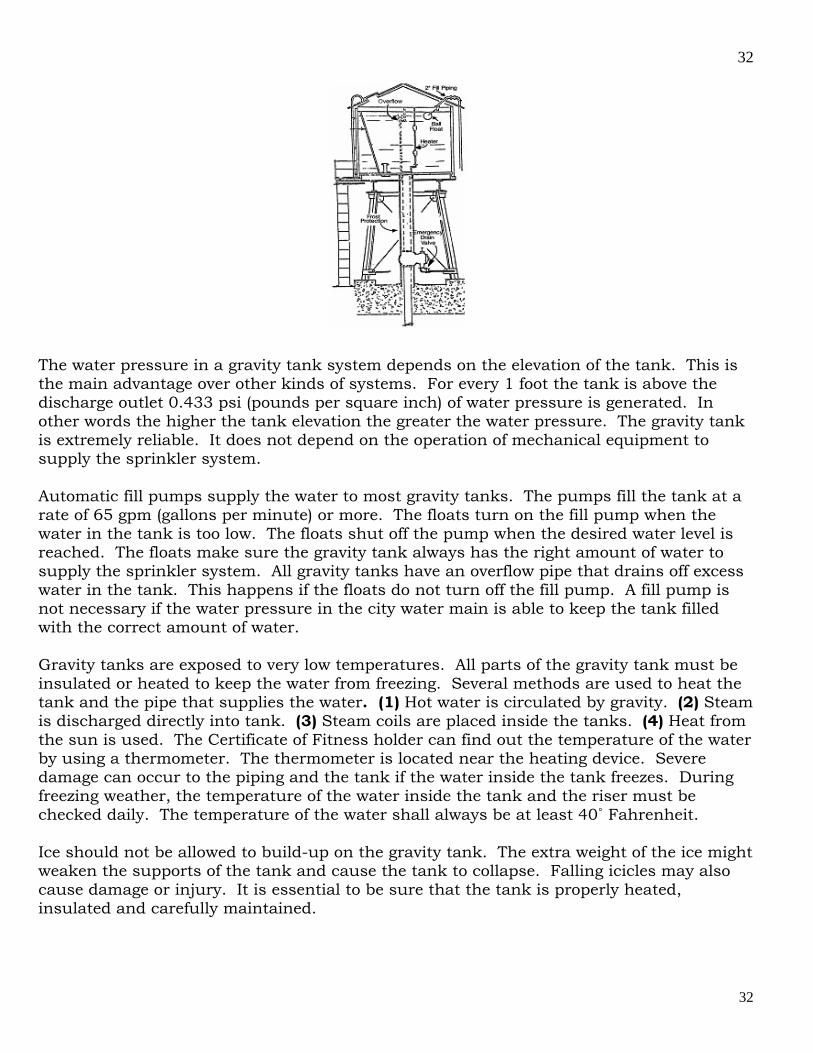
Supervision of the Pressure Tank - The pressure tank may also be supervised by an approved central station company which monitors the entire sprinkler system. Supervisory devices are installed in the pressure tank. These devices alert the central station company when there is a problem with the tank's water level, air pressure, and water temperature. The devices also alert the central station company when water has been discharged from the tank. When sprinkler heads have fused and water has been discharged from the tank the local fire house is notified. The central station company notifies the Certificate of Fitness holder when a problem is caused by equipment failure. Repairs and adjustments shall be made quickly to return the pressure tank to good working order. GRAVITY TANKS Gravity tanks are used for water storage. They are made of wood, steel or concrete. Gravity tanks are used as a primary or secondary water supply source for sprinkler systems. A gravity tank system delivers water from the tank through the sprinkler system without the use of pumping equipment. A gravity tank should be at least 25 feet above the highest line of sprinkler heads that it supplies. Tanks may be located on the tops of buildings or raised on tall supporting towers. Examples of a typical gravity tank are shown below and on the next page.
A Typical Gravity Tanks
32
32
The water pressure in a gravity tank system depends on the elevation of the tank. This is the main advantage over other kinds of systems. For every 1 foot the tank is above the discharge outlet 0.433 psi (pounds per square inch) of water pressure is generated. In other words the higher the tank elevation the greater the water pressure. The gravity tank is extremely reliable. It does not depend on the operation of mechanical equipment to supply the sprinkler system. Automatic fill pumps supply the water to most gravity tanks. The pumps fill the tank at a rate of 65 gpm (gallons per minute) or more. The floats turn on the fill pump when the water in the tank is too low. The floats shut off the pump when the desired water level is reached. The floats make sure the gravity tank always has the right amount of water to supply the sprinkler system. All gravity tanks have an overflow pipe that drains off excess water in the tank. This happens if the floats do not turn off the fill pump. A fill pump is not necessary if the water pressure in the city water main is able to keep the tank filled with the correct amount of water. Gravity tanks are exposed to very low temperatures. All parts of the gravity tank must be insulated or heated to keep the water from freezing. Several methods are used to heat the tank and the pipe that supplies the water. (1) Hot water is circulated by gravity. (2) Steam is discharged directly into tank. (3) Steam coils are placed inside the tanks. (4) Heat from the sun is used. The Certificate of Fitness holder can find out the temperature of the water by using a thermometer. The thermometer is located near the heating device. Severe damage can occur to the piping and the tank if the water inside the tank freezes. During freezing weather, the temperature of the water inside the tank and the riser must be checked daily. The temperature of the water shall always be at least 40˚ Fahrenheit. Ice should not be allowed to build-up on the gravity tank. The extra weight of the ice might weaken the supports of the tank and cause the tank to collapse. Falling icicles may also cause damage or injury. It is essential to be sure that the tank is properly heated, insulated and carefully maintained.
33
33
The gravity tank must always have a full supply of water. A full tank of water is needed to ensure the sprinkler system works properly during a fire. Keeping the tank full of water also prevents wooden tanks from shrinking. A full tank of water helps keep steel tanks from rusting. Gravity Tank Supervision - The gravity tank shall be constantly monitored ensure that the tank and its parts are working. Electrical supervision devices monitor the water temperature and the water level in the gravity tank. These devices send signals to an approved central station company about the water level and water temperature. The central station company notifies the Certificate of Fitness holder when a problem with the gravity tank is detected. The Certificate of Fitness holder shall correct the problem as soon as possible. The supervisory devices are sometimes called high and low alarms since they also send audible signals to alert the Certificate of Fitness holder or central station when there is a problem. The main reason a sprinkler system supplied by a gravity tank fails during a fire is not enough water in the tank. The sprinkler system cannot be supplied if there is not enough water in the tank. A proper water level shall be maintained.
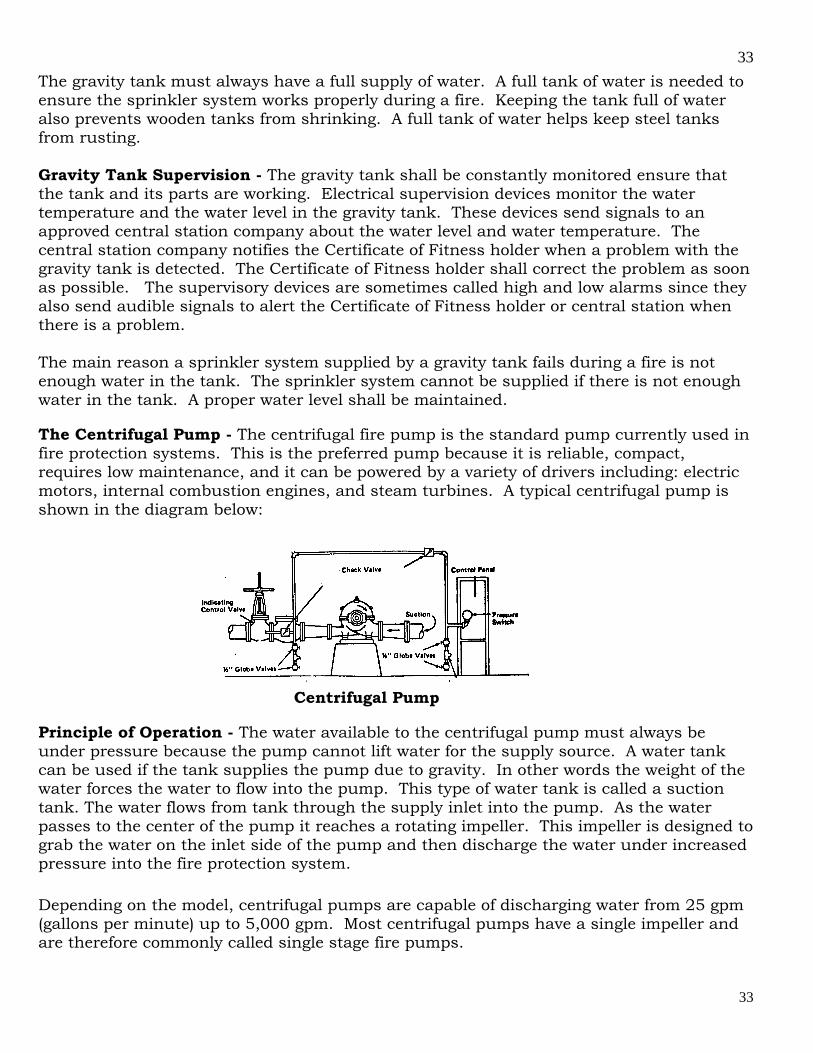
The Centrifugal Pump - The centrifugal fire pump is the standard pump currently used in fire protection systems. This is the preferred pump because it is reliable, compact, requires low maintenance, and it can be powered by a variety of drivers including: electric motors, internal combustion engines, and steam turbines. A typical centrifugal pump is shown in the diagram below:
Centrifugal Pump
Principle of Operation - The water available to the centrifugal pump must always be under pressure because the pump cannot lift water for the supply source. A water tank can be used if the tank supplies the pump due to gravity. In other words the weight of the water forces the water to flow into the pump. This type of water tank is called a suction tank. The water flows from tank through the supply inlet into the pump. As the water passes to the center of the pump it reaches a rotating impeller. This impeller is designed to grab the water on the inlet side of the pump and then discharge the water under increased pressure into the fire protection system. Depending on the model, centrifugal pumps are capable of discharging water from 25 gpm (gallons per minute) up to 5,000 gpm. Most centrifugal pumps have a single impeller and are therefore commonly called single stage fire pumps.
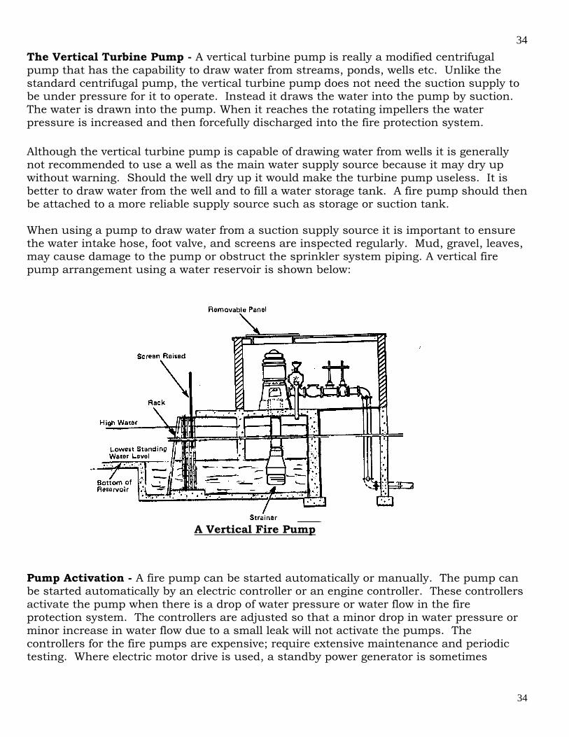
34
34
The Vertical Turbine Pump - A vertical turbine pump is really a modified centrifugal pump that has the capability to draw water from streams, ponds, wells etc. Unlike the standard centrifugal pump, the vertical turbine pump does not need the suction supply to be under pressure for it to operate. Instead it draws the water into the pump by suction. The water is drawn into the pump. When it reaches the rotating impellers the water pressure is increased and then forcefully discharged into the fire protection system. Although the vertical turbine pump is capable of drawing water from wells it is generally not recommended to use a well as the main water supply source because it may dry up without warning. Should the well dry up it would make the turbine pump useless. It is better to draw water from the well and to fill a water storage tank. A fire pump should then be attached to a more reliable supply source such as storage or suction tank. When using a pump to draw water from a suction supply source it is important to ensure the water intake hose, foot valve, and screens are inspected regularly. Mud, gravel, leaves, may cause damage to the pump or obstruct the sprinkler system piping. A vertical fire pump arrangement using a water reservoir is shown below:
A Vertical Fire Pump
Pump Activation - A fire pump can be started automatically or manually. The pump can be started automatically by an electric controller or an engine controller. These controllers activate the pump when there is a drop of water pressure or water flow in the fire protection system. The controllers are adjusted so that a minor drop in water pressure or minor increase in water flow due to a small leak will not activate the pumps. The controllers for the fire pumps are expensive; require extensive maintenance and periodic testing. Where electric motor drive is used, a standby power generator is sometimes
35
35
required. If an engine controller is used the appropriate fuel storage tanks should be filled and checked regularly. When manually activated pumps are installed they are usually used in combination with a gravity tank or a pressure tank. These tanks are designed to operate when there is a pressure drop in the fire protection system. The operation of the pressure tank and the triggering of its supervisory devices (alarms) alert the Certificate of Fitness holder that the fire pump must be activated. The Certificate of Fitness holder (or another responsible individual) should then manually activate the fire pump according to the manufacturer instructions. Manually operated fire pumps are often found in industrial and manufacturing occupancies having personnel on the premises at all times. The Certificate of Fitness holder may only activate a manually operated vertical fire pump arranged as described above. Sometimes remote push buttons are used to activate the pump. These remote push buttons are designed to start the pump but not to stop the fire pump. Pressure Maintenance Pumps (Jockey Pumps) – Pressure maintenance pumps, Some times referred to as jockey, or makeup pumps, are often found on sprinkler systems. These pumps are designed to automatically operate when there is a slight drop in pressure due to the leakage in the system or a pressure surge. The jockey pump restores the pressure in the fire protection system to the desired level. When the drop of pressure in the system greater than the capacity of the jockey pump the fire pump is activated. Booster pumps/special service pumps - Booster pumps are sometimes used in sprinkler systems. They small pumps with limited power are usually located in the basement or taking suction from gravity tanks. The booster pump is used when the water pressure available at the highest sprinkler head does not quite meet the needs of the sprinkler system. This small pump increases the water pressure in the sprinkler system until it reaches acceptable levels. The booster pump should not be confused with the fire pump or the jockey pump. Operation and Supervision - When fire pumps are activated by electric automatic controllers it is essential that they are constantly monitored to ensure the availability of the electrical power supply in case of an emergency. For this reason supervisory devices are installed on the pumps the alert the Certificate of Fitness holder and/or a central monitoring station when there is an electrical power failure. In cases where steam turbines or internal combustion engines are used similar supervisory devices are installed to signal when there is a problem with the controlling equipment.
Fire Pump Location - The fire pump should be housed in a room that is fire resistant or constructed noncombustible material. The pump room should be located as close as possible to the fire protection system. The pump room should be kept clean and accessible at all times. The fire pump, driver, and controller should be protected against possible interruption of service. The temperature inside the pump room should be maintained above 40 degrees Fahrenheit at all times to prevent freezing of the water. The pump room
36
36
should only be used for fire protection functions and not for general plant operations. No storage is permitted in this room. XI. HANGING, BRACING AND RESTRAINT OF SPRINKLER SYSTEM PIPING The structural support of the sprinkler system plays an integral part of system reliability. Missing or defective pipe hangers can cause the entire system to fail from piping rupturing or leaking. Great care and experience must be applied when evaluating the adequacy of the structural support of the system. Piping shall be supported from the building structure in accordance with the NYC Code requirements and NFPA # 13, 2002 edition. The annual visual inspection of system hanging components and bracing is the most complicated and difficult of all the tasks to be performed by the C of F holder. This reference is a starting point and by no means does it fully explain the various means, methods and requirements to adequately perform this annual inspection task. Chapter 9 of the NFPA#13 2002 edition describes in great detail the fundamentals of hanger design and installation and should be used as a reference guide for accurate inspection results that will be reported to the owner and FDNY. There are any numbers of different deficiencies that may be found during the inspection process. They may include system supports being disturbed by the movement of adjacent equipment, deflection or sagging of the building structure, deterioration of the portion of the structure used to support the system and attaching excessive loads to hanging components or piping. Unapproved or makeshift hangers such as perforated strapping or bailing wire are prohibited. Nails shall not be used to fasten the system or building attachments to the structure. Hangers used with plastic piping must be listed for use with the piping material. A visual inspection of the system is performed from the floor to determine if the hangers, bracing and restraints are in place and if the piping has moved from its original location and position. This can be observed if the hanger rods or piping attachments are not being supported adequately from the building, bent, misaligned, loose or missing. Shifting of the system may occur during pressure surges, water hammer, alterations, testing, or operation. The visual inspection of hanging and bracing for sprinkler systems is not required for piping concealed by building construction above ceilings and in concealed spaces. When there is an indication of concealed piping system’s sprinklers heads either too far above or below a hung ceiling, further investigation is required to determine if hangers and supports are defective or missing. No other components shall be supported using the sprinkler system piping or hanger assemblies supporting the system.
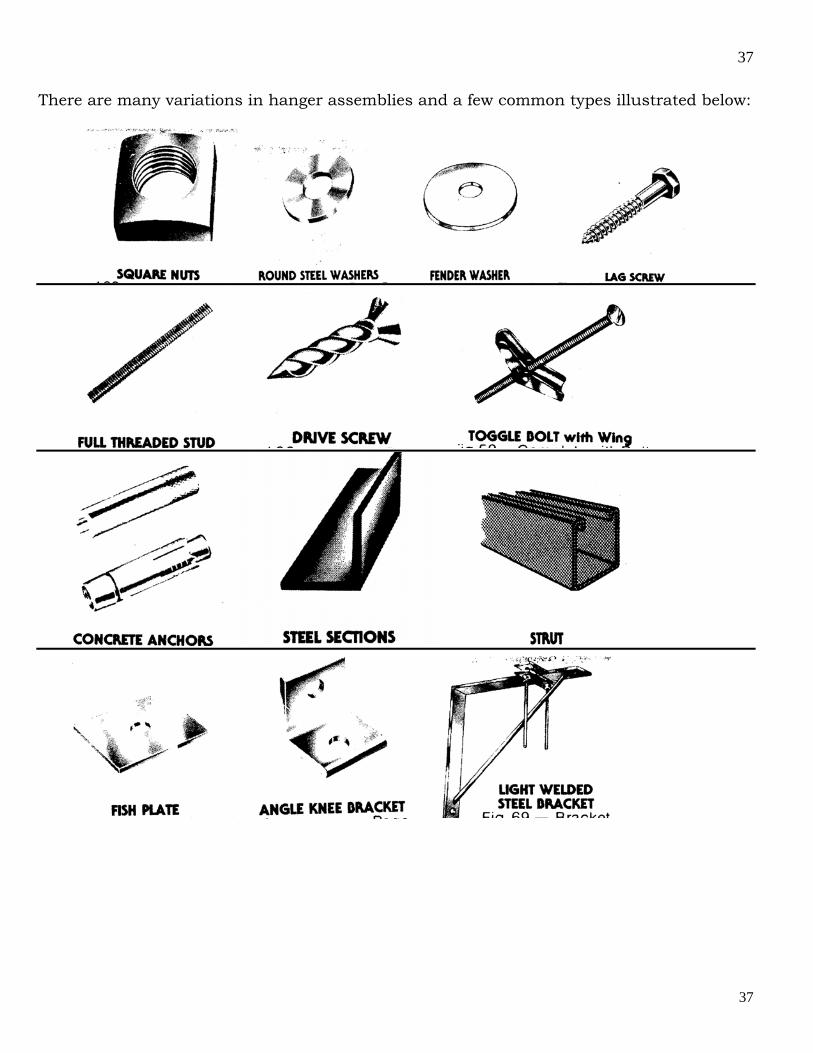
37
37
There are many variations in hanger assemblies and a few common types illustrated below:
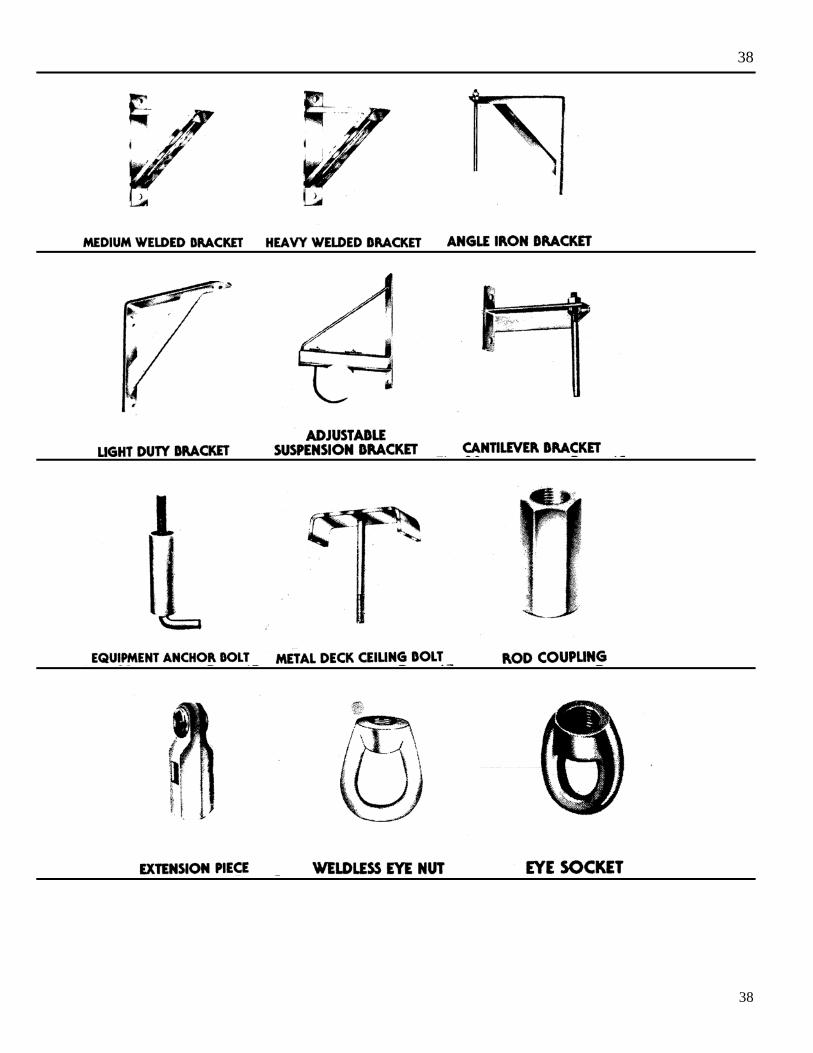
38
38
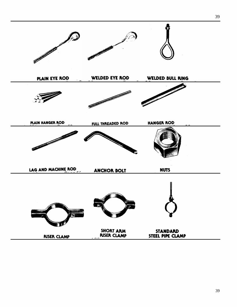
39
39
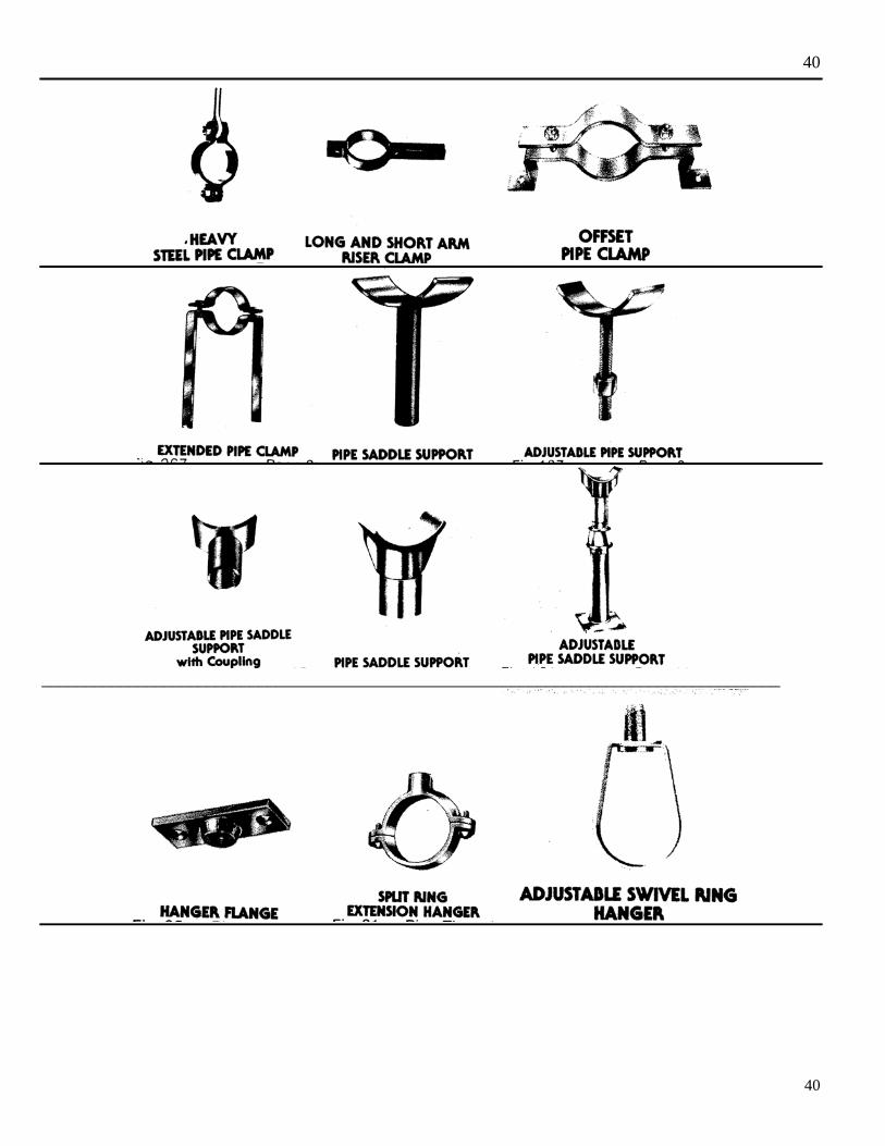
40
40
_____________________________________________________________________________________
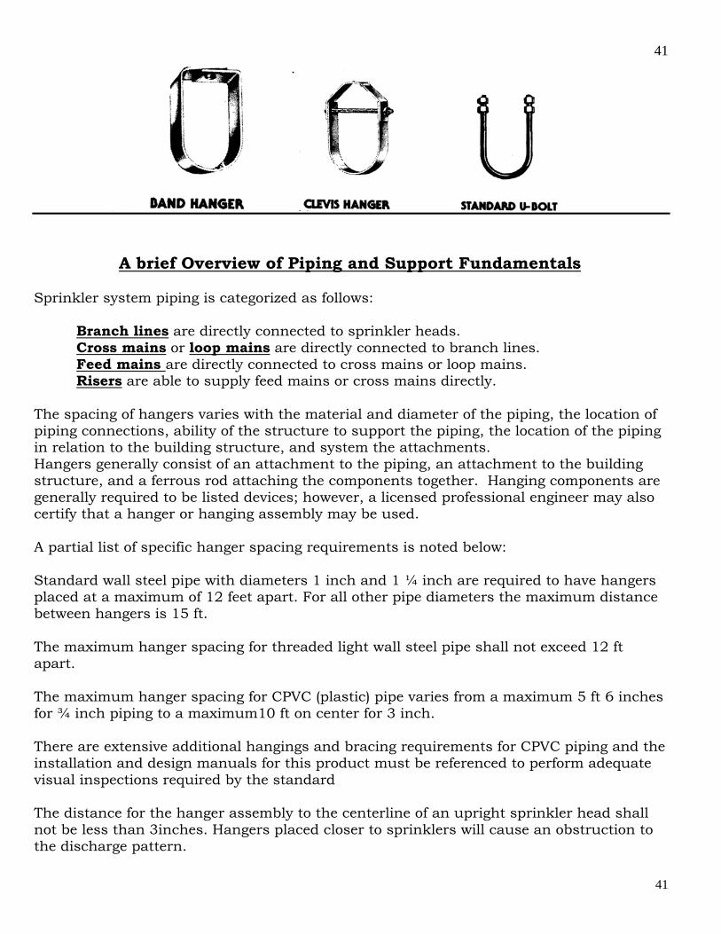
41
41
A brief Overview of Piping and Support Fundamentals
Sprinkler system piping is categorized as follows:
Branch lines are directly connected to sprinkler heads. Cross mains or loop mains are directly connected to branch lines. Feed mains are directly connected to cross mains or loop mains. Risers are able to supply feed mains or cross mains directly.
The spacing of hangers varies with the material and diameter of the piping, the location of piping connections, ability of the structure to support the piping, the location of the piping in relation to the building structure, and system the attachments. Hangers generally consist of an attachment to the piping, an attachment to the building structure, and a ferrous rod attaching the components together. Hanging components are generally required to be listed devices; however, a licensed professional engineer may also certify that a hanger or hanging assembly may be used. A partial list of specific hanger spacing requirements is noted below: Standard wall steel pipe with diameters 1 inch and 1 ¼ inch are required to have hangers placed at a maximum of 12 feet apart. For all other pipe diameters the maximum distance between hangers is 15 ft. The maximum hanger spacing for threaded light wall steel pipe shall not exceed 12 ft apart. The maximum hanger spacing for CPVC (plastic) pipe varies from a maximum 5 ft 6 inches for ¾ inch piping to a maximum10 ft on center for 3 inch. There are extensive additional hangings and bracing requirements for CPVC piping and the installation and design manuals for this product must be referenced to perform adequate visual inspections required by the standard The distance for the hanger assembly to the centerline of an upright sprinkler head shall not be less than 3inches. Hangers placed closer to sprinklers will cause an obstruction to the discharge pattern.

42
42
For systems operating at less than 100 psi, the unsupported length between the end sprinkler head and the last hanger on the line shall not exceed 36 inches for 1 inch piping, 48 inches for 1 ¼ inch piping, and 60 inches for piping 1 ½ inch or larger. For systems operating at pressures of 100 psi or greater, the hanger closest to the last sprinkler on the line shall be of the type that prevents the upward movement of the piping within the hanger assembly. This can be accomplished by the use of a surge restrainer. The cumulative length of an unsupported arm over to a sprinkler head, sprinkler drop, or sprinkler sprig-up shall not exceed 24 inches for steel pipe and 12 inches for copper pipe. System risers (vertical piping passing from floor to floor) shall be supported with riser clamps and hangers located within 24 inches of the centerline of the riser. The distance between supports for risers shall not exceed 25 feet. The minimum size hanger rods are required as follows: Pipe Diameter in inches Rod Diameter in inches Up to and including 4 3/8 Five, Six and Eight ½ Ten and Twelve 5/8
Seismic Restraints The NYC Building Code adopted earthquake code requirements. This reclassification requires the installation of sway bracing for earthquake protection be installed on sprinkler systems in buildings built after 1998. The system piping shall be braced to resist both lateral and longitudinal horizontal seismic loads and to prevent vertical motion resulting from seismic events. Lateral braces shall be spaced at a maximum of 40 feet on centers and are required on all piping 2 ½ inch and larger. The distance from the last brace to the end of the pipe being braced shall not exceed 20 feet. Longitudinal braces shall be spaced at a maximum of 80 feet on centers and are to be provided on feed and cross mains. Piping shall be protected against damage where subject to earthquakes by the use of flexible couplings for piping 2 ½ inch and larger. Flexible connection shall also be provided at building expansion joints, and within 24 inches of top and bottom of the piping dropping down to in rack sprinklers and mezzanines regardless of pipe size. To avoid damage to piping passing through holes in platforms, walls, floors and foundations, a clearance of at least 2 inches shall be provided around the piping and the
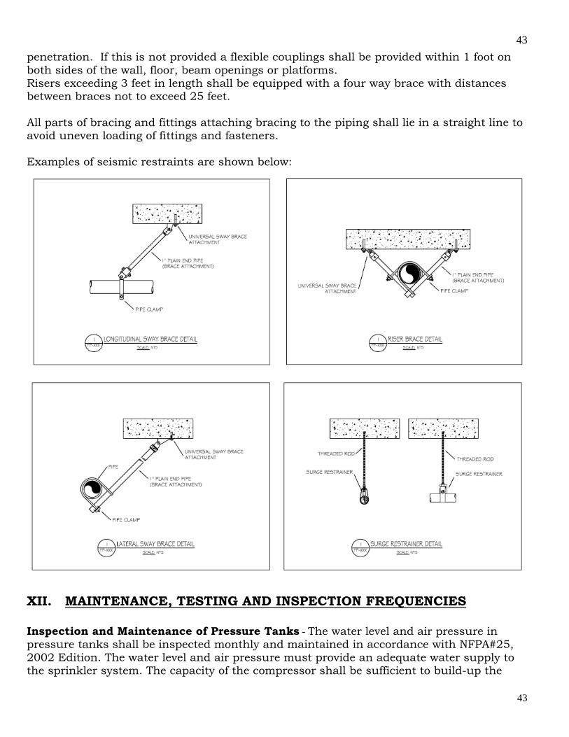
43
43
penetration. If this is not provided a flexible couplings shall be provided within 1 foot on both sides of the wall, floor, beam openings or platforms. Risers exceeding 3 feet in length shall be equipped with a four way brace with distances between braces not to exceed 25 feet. All parts of bracing and fittings attaching bracing to the piping shall lie in a straight line to avoid uneven loading of fittings and fasteners. Examples of seismic restraints are shown below:
XII. MAINTENANCE, TESTING AND INSPECTION FREQUENCIES Inspection and Maintenance of Pressure Tanks - The water level and air pressure in pressure tanks shall be inspected monthly and maintained in accordance with NFPA#25, 2002 Edition. The water level and air pressure must provide an adequate water supply to the sprinkler system. The capacity of the compressor shall be sufficient to build-up the
44
44
tank pressure to 75 psig within 3 hours or less. The water gauge valve shall be opened to examine the water level. When the valve is opened the water will flow into the gauge. This allows the Certificate of Fitness holder to compare the water level in the tank to the desired water level mark. Adjustments to the water level should be made as needed. After visually inspecting the water gauge valve, the valve should be closed. When the valve is closed, the water and air in the tank are isolated from the sight glass. If the gauge glass breaks the volume of water and the air pressure are not affected. The inside of pressure tanks shall be inspected carefully every three years. Rusting in the tank may require repainting or other repairs. The inside of the tank should be thoroughly scraped, wire brushed and repainted. No foreign materials should be allowed to fall into the sprinkler system. The temperature inside the structure housing the pressure tank should be checked daily during cold weather to make sure that the temperature is at least 40˚ Fahrenheit at all times. Inspection and Maintenance of the Gravity Tank - The gravity tank should be regularly inspected and maintained in accordance with NFPA #25, 2002 edition. Maintenance is needed to be sure that the tank functions correctly. Tanks are to be painted regularly to prevent rusting. Before the inside of a gravity tank is repainted the surface should be thoroughly dried. All loose paint, rust, scale, and other surface contamination should be removed. The outside of the gravity tank will require local patching. A complete finish coat of paint is needed when the paint has weathered thin. A new coat of paint also improves the appearance of the tank after it has been patched. Painters shall be careful that scrapings or other foreign materials do not fall down the outlet into the sprinkler piping. The discharge outlet may be covered for protection during repairs. Only a few sheets of paper or a paper bag tied over the end of the settling basin stub should be used. The paper should be removed upon immediately after the job is finished. It is best if gravity tanks are used only for fire protection and for no other purpose. Tanks used for other purposes need to be refilled more often. The tanks become settling basins for sediment mixed in with the water. This sediment is then drawn into the piping. This may cause the sprinkler system to become clogged and not work properly. The local fire house should always be notified when a tank cannot be used for any reason.
Pump Inspection and Maintenance - In order to ensure the reliable operation of the pump in the case of an emergency regular inspections and maintenance shall be conducted by the Certificate of Fitness holder. The pump should be activated each week and run for 10 minutes in accordance to the manufacturer specifications to ensure that it is functioning properly. When the pump is in operation a small water leak on the pump bearings is desirable and should not be considered a malfunction. If an automatic controller operates the fire pump the pump shall be activated by reducing the water pressure in the system. This can be done by opening the test drain or initiating a large water flow from the system. By starting the fire pump this way the Certificate of

45
45
Fitness holder can determine if the automatic controller is working properly. Care should be taken to make sure that the pump does not overheat while conducting the test. The centrifugal pump relies on the water supply for cooling and lubrication and should never be operated without the pump being supplied with water. A visual inspection of all parts of the pump and the controlling equipment should also be conducted each week. This inspection should include the condition and reliability of the power supply. If any problems are discovered with the equipment immediate action should be taken to correct the problem. Fire pumps should be fully tested annually to make sure that the pump, driver, power supply and all other parts are functioning properly. COMMON DEFICIENCIES Common Deficiencies - The most common sprinkler system deficiencies include painted or loaded sprinkler heads, building contents located less than 18 inches below sprinkler deflectors, changes from the original wall locations, ceiling heights, and positioning of mechanical equipment. For concealed sprinkler systems, cover plates with non-factory coatings and the lack of required gap between cover plate and ceiling and blocking of the spray patterns from light fixtures close to the sprinklers are the most common deficiencies seen in the field. Missing trim or cover plates not attached properly to sprinklers may indicate hanger deficiencies and may not allow the sprinkler deflectors to drop below the ceiling blocking the spray pattern. The C of F holder shall assume that the system being inspected is installed is accordance to the NYC Building Code in effect at the time of installation. The C of F holder is to report those items of change that impact the system components regarding, compliance with any retroactive requirements, the condition of the water supply control valves, water and air levels in reserve tanks and condition of same, unusual changes in water supply or system pressures, condition and accessibility of control valves, fire department connections, clearance around sprinkler heads, accessibility of curb valve box ,system control valves , required signage, attachments to piping other than system components, misaligned piping due to impact, missing pipe hangers and supports, excessive operation of pressure relief valves, easily recognized recalled sprinkler heads and visible leakage. Factors that may require further investigation: Installations that don’t appear to be correct including sprinkler heads located more than 22 inches below the ceiling or structure, sprinklers not installed in accordance with their listing, using sprinklers with different RTI in the same protected area or the wrong RTI for the occupancy classification, undersized piping, incompatible piping materials, flexible sprinkler hoses not attached to the building structure, along with areas of the building not protected by the sprinkler system all require further investigation by a qualified MFSPC. When sprinklers are replaced, the following information is critical to be certain that the correct devices have been used. Sprinklers with different diameter glass bulbs will have a different RTI and must not be used together in the same compartment.
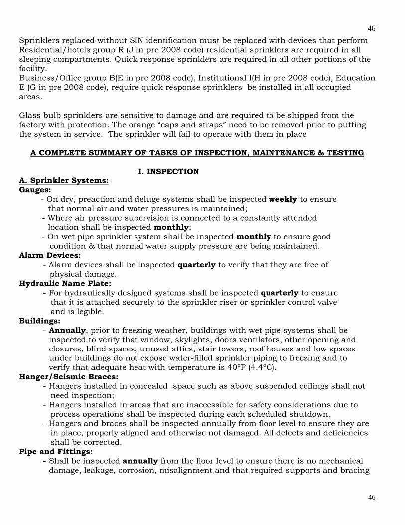
46
46
Sprinklers replaced without SIN identification must be replaced with devices that perform Residential/hotels group R (J in pre 2008 code) residential sprinklers are required in all sleeping compartments. Quick response sprinklers are required in all other portions of the facility. Business/Office group B(E in pre 2008 code), Institutional I(H in pre 2008 code), Education E (G in pre 2008 code), require quick response sprinklers be installed in all occupied areas. Glass bulb sprinklers are sensitive to damage and are required to be shipped from the factory with protection. The orange “caps and straps” need to be removed prior to putting the system in service. The sprinkler will fail to operate with them in place
A COMPLETE SUMMARY OF TASKS OF INSPECTION, MAINTENANCE & TESTING
I. INSPECTION A. Sprinkler Systems: Gauges: - On dry, preaction and deluge systems shall be inspected weekly to ensure that normal air and water pressures is maintained; - Where air pressure supervision is connected to a constantly attended location shall be inspected monthly; - On wet pipe sprinkler system shall be inspected monthly to ensure good condition & that normal water supply pressure are being maintained. Alarm Devices:
- Alarm devices shall be inspected quarterly to verify that they are free of physical damage. Hydraulic Name Plate:
- For hydraulically designed systems shall be inspected quarterly to ensure that it is attached securely to the sprinkler riser or sprinkler control valve and is legible.
Buildings: - Annually, prior to freezing weather, buildings with wet pipe systems shall be
inspected to verify that window, skylights, doors ventilators, other opening and closures, blind spaces, unused attics, stair towers, roof houses and low spaces under buildings do not expose water-filled sprinkler piping to freezing and to verify that adequate heat with temperature is 40ºF (4.4ºC).
Hanger/Seismic Braces: - Hangers installed in concealed space such as above suspended ceilings shall not need inspection; - Hangers installed in areas that are inaccessible for safety considerations due to process operations shall be inspected during each scheduled shutdown. - Hangers and braces shall be inspected annually from floor level to ensure they are in place, properly aligned and otherwise not damaged. All defects and deficiencies shall be corrected.
Pipe and Fittings: - Shall be inspected annually from the floor level to ensure there is no mechanical
damage, leakage, corrosion, misalignment and that required supports and bracing
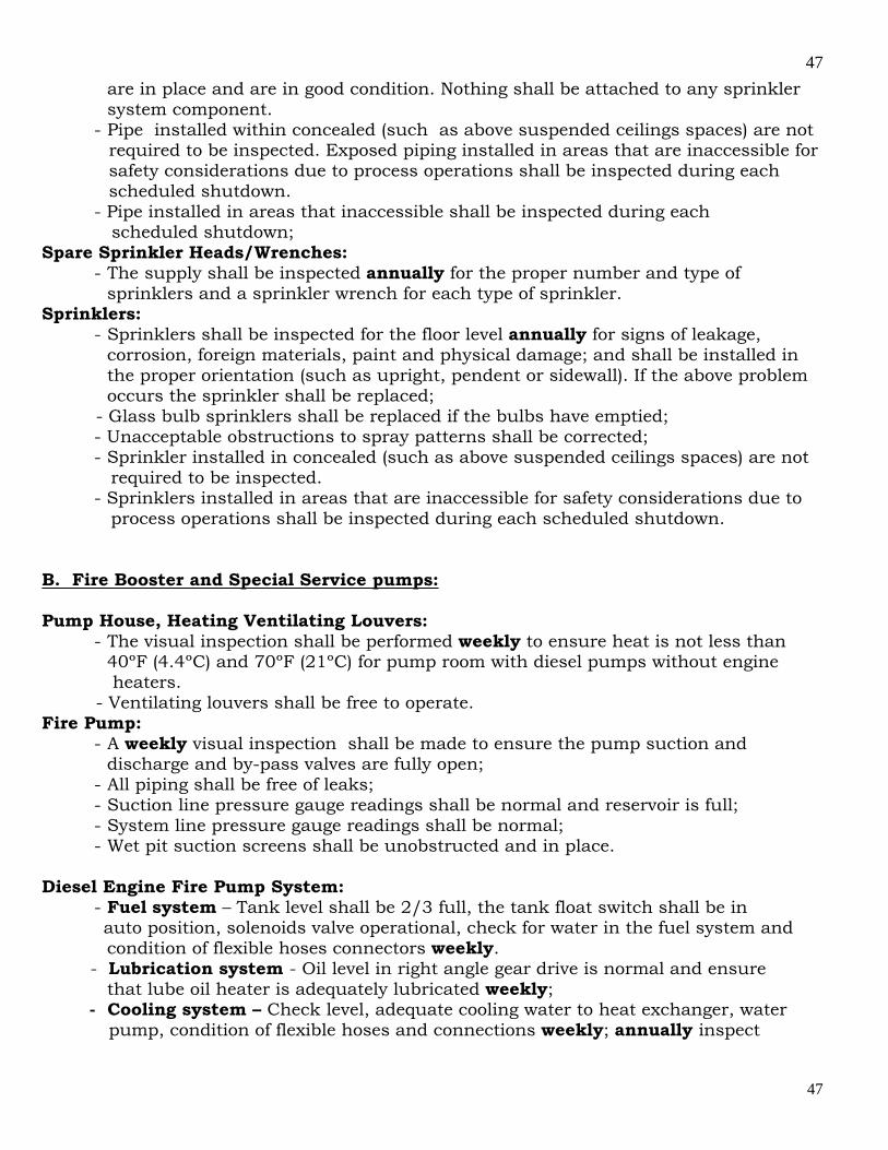
47
47
are in place and are in good condition. Nothing shall be attached to any sprinkler system component.
- Pipe installed within concealed (such as above suspended ceilings spaces) are not required to be inspected. Exposed piping installed in areas that are inaccessible for safety considerations due to process operations shall be inspected during each scheduled shutdown.
- Pipe installed in areas that inaccessible shall be inspected during each scheduled shutdown;
Spare Sprinkler Heads/Wrenches: - The supply shall be inspected annually for the proper number and type of
sprinklers and a sprinkler wrench for each type of sprinkler. Sprinklers:
- Sprinklers shall be inspected for the floor level annually for signs of leakage, corrosion, foreign materials, paint and physical damage; and shall be installed in the proper orientation (such as upright, pendent or sidewall). If the above problem occurs the sprinkler shall be replaced; - Glass bulb sprinklers shall be replaced if the bulbs have emptied;
- Unacceptable obstructions to spray patterns shall be corrected; - Sprinkler installed in concealed (such as above suspended ceilings spaces) are not required to be inspected. - Sprinklers installed in areas that are inaccessible for safety considerations due to process operations shall be inspected during each scheduled shutdown.
B. Fire Booster and Special Service pumps: Pump House, Heating Ventilating Louvers:
- The visual inspection shall be performed weekly to ensure heat is not less than 40ºF (4.4ºC) and 70ºF (21ºC) for pump room with diesel pumps without engine heaters. - Ventilating louvers shall be free to operate.
Fire Pump: - A weekly visual inspection shall be made to ensure the pump suction and
discharge and by-pass valves are fully open; - All piping shall be free of leaks; - Suction line pressure gauge readings shall be normal and reservoir is full; - System line pressure gauge readings shall be normal; - Wet pit suction screens shall be unobstructed and in place.
Diesel Engine Fire Pump System:
- Fuel system – Tank level shall be 2/3 full, the tank float switch shall be in auto position, solenoids valve operational, check for water in the fuel system and condition of flexible hoses connectors weekly. - Lubrication system - Oil level in right angle gear drive is normal and ensure that lube oil heater is adequately lubricated weekly;
- Cooling system – Check level, adequate cooling water to heat exchanger, water pump, condition of flexible hoses and connections weekly; annually inspect
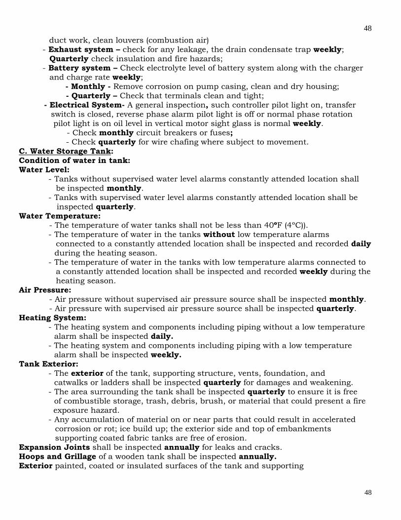
48
48
duct work, clean louvers (combustion air) - Exhaust system – check for any leakage, the drain condensate trap weekly;
Quarterly check insulation and fire hazards; - Battery system – Check electrolyte level of battery system along with the charger
and charge rate weekly; - Monthly - Remove corrosion on pump casing, clean and dry housing; - Quarterly – Check that terminals clean and tight; - Electrical System- A general inspection, such controller pilot light on, transfer switch is closed, reverse phase alarm pilot light is off or normal phase rotation pilot light is on oil level in vertical motor sight glass is normal weekly.
- Check monthly circuit breakers or fuses; - Check quarterly for wire chafing where subject to movement.
C. Water Storage Tank: Condition of water in tank: Water Level:
- Tanks without supervised water level alarms constantly attended location shall be inspected monthly.
- Tanks with supervised water level alarms constantly attended location shall be inspected quarterly. Water Temperature: - The temperature of water tanks shall not be less than 40ºF (4ºC)).
- The temperature of water in the tanks without low temperature alarms connected to a constantly attended location shall be inspected and recorded daily during the heating season.
- The temperature of water in the tanks with low temperature alarms connected to a constantly attended location shall be inspected and recorded weekly during the heating season.
Air Pressure: - Air pressure without supervised air pressure source shall be inspected monthly. - Air pressure with supervised air pressure source shall be inspected quarterly. Heating System:
- The heating system and components including piping without a low temperature alarm shall be inspected daily.
- The heating system and components including piping with a low temperature alarm shall be inspected weekly. Tank Exterior:
- The exterior of the tank, supporting structure, vents, foundation, and catwalks or ladders shall be inspected quarterly for damages and weakening.
- The area surrounding the tank shall be inspected quarterly to ensure it is free of combustible storage, trash, debris, brush, or material that could present a fire
exposure hazard. - Any accumulation of material on or near parts that could result in accelerated
corrosion or rot; ice build up; the exterior side and top of embankments supporting coated fabric tanks are free of erosion.
Expansion Joints shall be inspected annually for leaks and cracks. Hoops and Grillage of a wooden tank shall be inspected annually. Exterior painted, coated or insulated surfaces of the tank and supporting
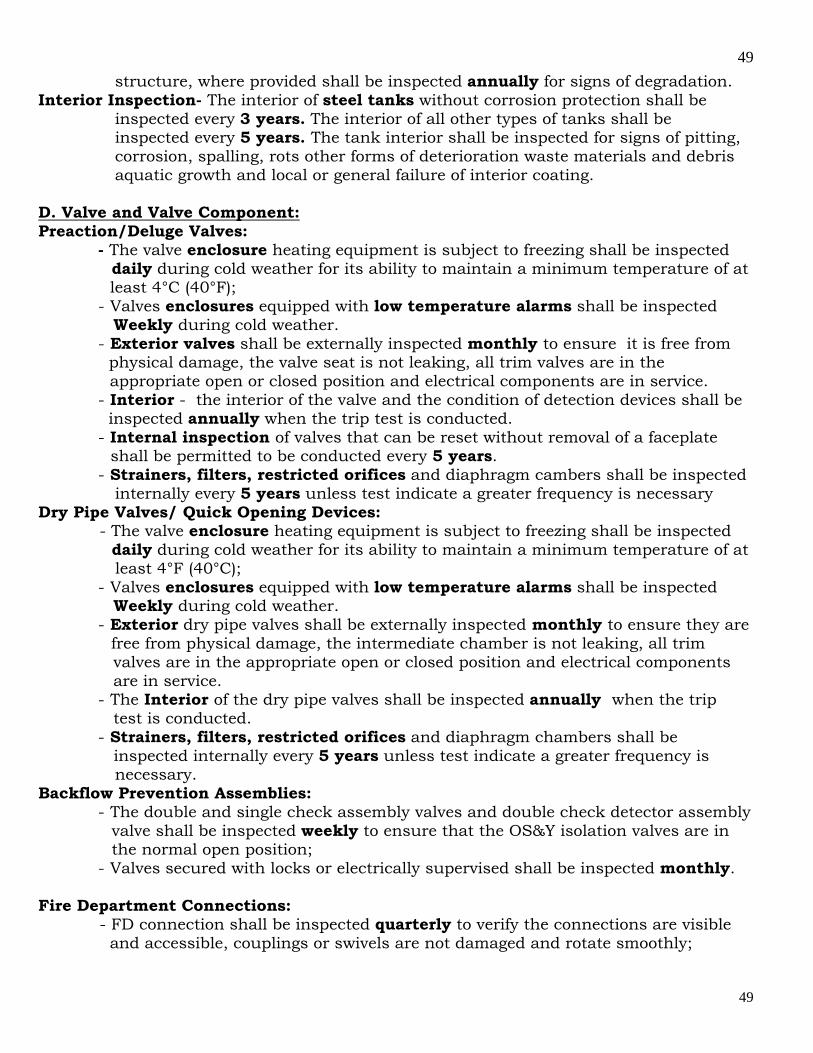
49
49
structure, where provided shall be inspected annually for signs of degradation. Interior Inspection- The interior of steel tanks without corrosion protection shall be inspected every 3 years. The interior of all other types of tanks shall be inspected every 5 years. The tank interior shall be inspected for signs of pitting, corrosion, spalling, rots other forms of deterioration waste materials and debris aquatic growth and local or general failure of interior coating. D. Valve and Valve Component: Preaction/Deluge Valves: - The valve enclosure heating equipment is subject to freezing shall be inspected
daily during cold weather for its ability to maintain a minimum temperature of at least 4°C (40°F);
- Valves enclosures equipped with low temperature alarms shall be inspected Weekly during cold weather.
- Exterior valves shall be externally inspected monthly to ensure it is free from physical damage, the valve seat is not leaking, all trim valves are in the appropriate open or closed position and electrical components are in service.
- Interior - the interior of the valve and the condition of detection devices shall be inspected annually when the trip test is conducted.
- Internal inspection of valves that can be reset without removal of a faceplate shall be permitted to be conducted every 5 years.
- Strainers, filters, restricted orifices and diaphragm cambers shall be inspected internally every 5 years unless test indicate a greater frequency is necessary Dry Pipe Valves/ Quick Opening Devices: - The valve enclosure heating equipment is subject to freezing shall be inspected
daily during cold weather for its ability to maintain a minimum temperature of at least 4°F (40°C);
- Valves enclosures equipped with low temperature alarms shall be inspected Weekly during cold weather.
- Exterior dry pipe valves shall be externally inspected monthly to ensure they are free from physical damage, the intermediate chamber is not leaking, all trim valves are in the appropriate open or closed position and electrical components are in service.
- The Interior of the dry pipe valves shall be inspected annually when the trip test is conducted.
- Strainers, filters, restricted orifices and diaphragm chambers shall be inspected internally every 5 years unless test indicate a greater frequency is necessary. Backflow Prevention Assemblies:
- The double and single check assembly valves and double check detector assembly valve shall be inspected weekly to ensure that the OS&Y isolation valves are in the normal open position;
- Valves secured with locks or electrically supervised shall be inspected monthly. Fire Department Connections: - FD connection shall be inspected quarterly to verify the connections are visible and accessible, couplings or swivels are not damaged and rotate smoothly;
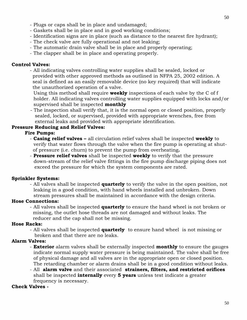
50
50
- Plugs or caps shall be in place and undamaged; - Gaskets shall be in place and in good working conditions; - Identification signs are in place (such as distance to the nearest fire hydrant); - The check valve are fully operational and not leaking; - The automatic drain valve shall be in place and properly operating; - The clapper shall be in place and operating properly.
Control Valves:
- All indicating valves controlling water supplies shall be sealed, locked or provided with other approved methods as outlined in NFPA 25, 2002 edition. A seal is defined as an easily removable device (no key required) that will indicate the unauthorized operation of a valve. Using this method shall require weekly inspections of each valve by the C of f holder. All indicating valves controlling water supplies equipped with locks and/or supervised shall be inspected monthly
- The inspection shall verify that, it is the normal open or closed position, properly sealed, locked, or supervised, provided with appropriate wrenches, free from external leaks and provided with appropriate identification. Pressure Reducing and Relief Valves: Fire Pumps:
- Casing relief valves – all circulation relief valves shall be inspected weekly to verify that water flows through the valve when the fire pump is operating at shut- of pressure (i.e. churn) to prevent the pump from overheating.
- Pressure relief valves shall be inspected weekly to verify that the pressure down-stream of the relief valve fittings in the fire pump discharge piping does not exceed the pressure for which the system components are rated.
Sprinkler Systems: - All valves shall be inspected quarterly to verify the valve in the open position, not
leaking in a good condition, with hand wheels installed and unbroken. Down stream pressures shall be maintained in accordance with the design criteria.
Hose Connections: - All valves shall be inspected quarterly to ensure the hand wheel is not broken or
missing, the outlet hose threads are not damaged and without leaks. The reducer and the cap shall not be missing.
Hose Racks: - All valves shall be inspected quarterly to ensure hand wheel is not missing or
broken and that there are no leaks. Alarm Valves:
- Exterior alarm valves shall be externally inspected monthly to ensure the gauges indicate normal supply water pressure is being maintained. The valve shall be free of physical damage and all valves are in the appropriate open or closed position. The retarding chamber or alarm drains shall be in a good condition without leaks.
- All alarm valve and their associated strainers, filters, and restricted orifices shall be inspected internally every 5 years unless test indicate a greater frequency is necessary. Check Valves -
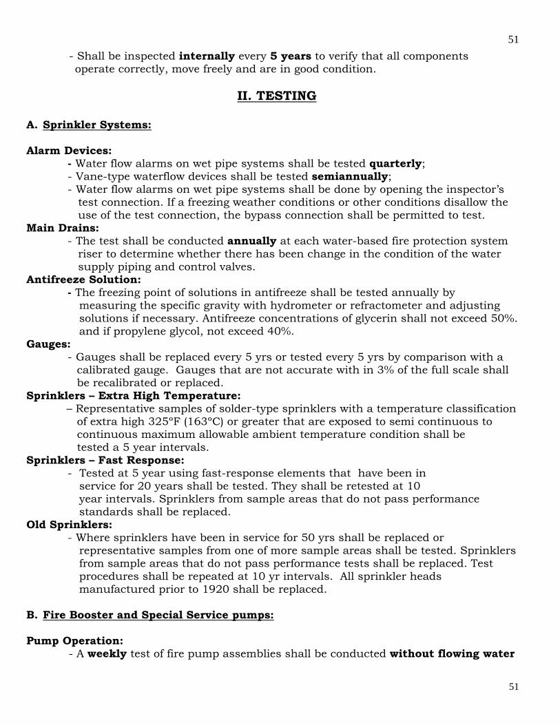
51
51
- Shall be inspected internally every 5 years to verify that all components operate correctly, move freely and are in good condition. II. TESTING A. Sprinkler Systems: Alarm Devices:
- Water flow alarms on wet pipe systems shall be tested quarterly; - Vane-type waterflow devices shall be tested semiannually; - Water flow alarms on wet pipe systems shall be done by opening the inspector’s
test connection. If a freezing weather conditions or other conditions disallow the use of the test connection, the bypass connection shall be permitted to test.
Main Drains: - The test shall be conducted annually at each water-based fire protection system
riser to determine whether there has been change in the condition of the water supply piping and control valves.
Antifreeze Solution: - The freezing point of solutions in antifreeze shall be tested annually by measuring the specific gravity with hydrometer or refractometer and adjusting solutions if necessary. Antifreeze concentrations of glycerin shall not exceed 50%. and if propylene glycol, not exceed 40%. Gauges:
- Gauges shall be replaced every 5 yrs or tested every 5 yrs by comparison with a calibrated gauge. Gauges that are not accurate with in 3% of the full scale shall be recalibrated or replaced.
Sprinklers – Extra High Temperature: – Representative samples of solder-type sprinklers with a temperature classification of extra high 325ºF (163ºC) or greater that are exposed to semi continuous to continuous maximum allowable ambient temperature condition shall be tested a 5 year intervals.
Sprinklers – Fast Response: - Tested at 5 year using fast-response elements that have been in
service for 20 years shall be tested. They shall be retested at 10 year intervals. Sprinklers from sample areas that do not pass performance standards shall be replaced. Old Sprinklers:
- Where sprinklers have been in service for 50 yrs shall be replaced or representative samples from one of more sample areas shall be tested. Sprinklers from sample areas that do not pass performance tests shall be replaced. Test procedures shall be repeated at 10 yr intervals. All sprinkler heads manufactured prior to 1920 shall be replaced. B. Fire Booster and Special Service pumps: Pump Operation: - A weekly test of fire pump assemblies shall be conducted without flowing water
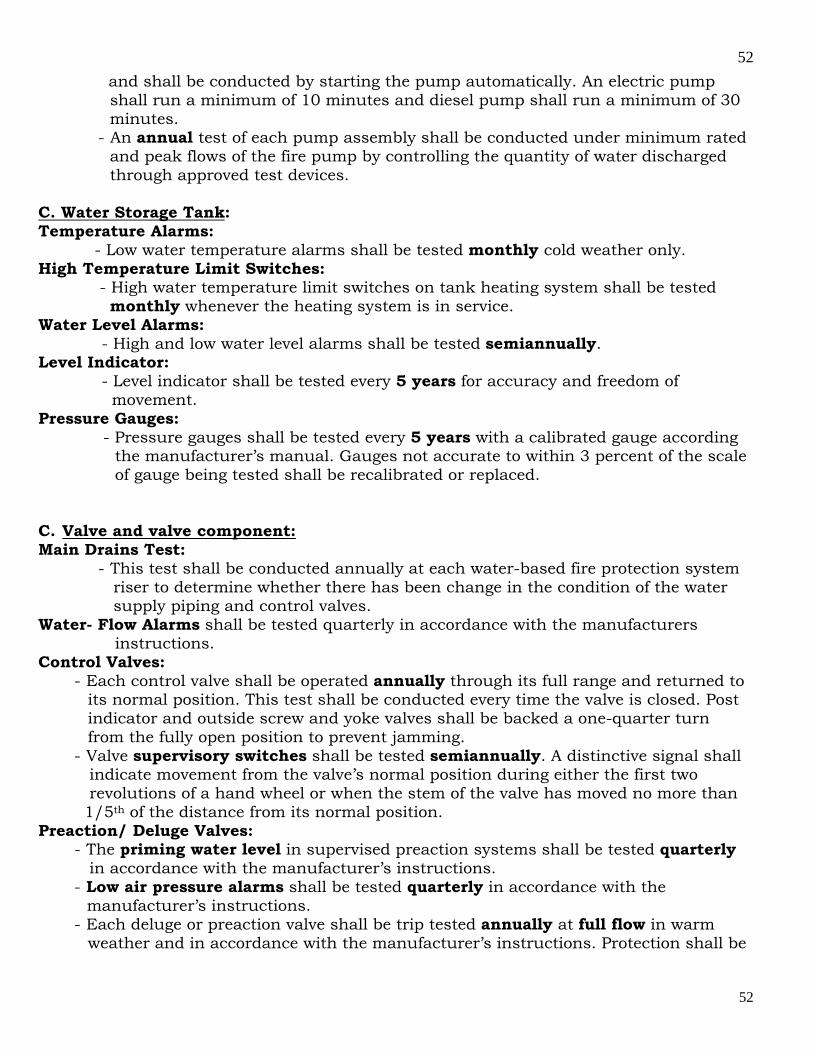
52
52
and shall be conducted by starting the pump automatically. An electric pump shall run a minimum of 10 minutes and diesel pump shall run a minimum of 30 minutes.
- An annual test of each pump assembly shall be conducted under minimum rated and peak flows of the fire pump by controlling the quantity of water discharged through approved test devices. C. Water Storage Tank: Temperature Alarms: - Low water temperature alarms shall be tested monthly cold weather only. High Temperature Limit Switches: - High water temperature limit switches on tank heating system shall be tested monthly whenever the heating system is in service. Water Level Alarms:
- High and low water level alarms shall be tested semiannually. Level Indicator:
- Level indicator shall be tested every 5 years for accuracy and freedom of movement.
Pressure Gauges: - Pressure gauges shall be tested every 5 years with a calibrated gauge according
the manufacturer’s manual. Gauges not accurate to within 3 percent of the scale of gauge being tested shall be recalibrated or replaced. C. Valve and valve component: Main Drains Test:
- This test shall be conducted annually at each water-based fire protection system riser to determine whether there has been change in the condition of the water supply piping and control valves.
Water- Flow Alarms shall be tested quarterly in accordance with the manufacturers instructions. Control Valves:
- Each control valve shall be operated annually through its full range and returned to its normal position. This test shall be conducted every time the valve is closed. Post indicator and outside screw and yoke valves shall be backed a one-quarter turn from the fully open position to prevent jamming.
- Valve supervisory switches shall be tested semiannually. A distinctive signal shall indicate movement from the valve’s normal position during either the first two revolutions of a hand wheel or when the stem of the valve has moved no more than 1/5th of the distance from its normal position. Preaction/ Deluge Valves:
- The priming water level in supervised preaction systems shall be tested quarterly in accordance with the manufacturer’s instructions.
- Low air pressure alarms shall be tested quarterly in accordance with the manufacturer’s instructions.
- Each deluge or preaction valve shall be trip tested annually at full flow in warm weather and in accordance with the manufacturer’s instructions. Protection shall be

53
53
provided for any devices subject to damage by system discharge during tests. Dry Pipe Valves / quick – opening Devices:
- The priming water level shall be tested quarterly. High priming water levels can affect the operation of supervisory air or nitrogen pressure maintenance device. Testing the water level is done by opening the priming level test valve, if water flows, drain it, close the valve when water stops flowing and air discharges, if air discharges when the valve is opened, the priming water level could be too low. To add priming water, refer to manufacturer’s instructions. - Low air pressure alarms shall be tested quarterly in accordance with the manufacturer’s instructions. - Quick-opening devices shall be tested quarterly following the below procedures: - Close the system control valve, open the main drain valve and keep it in the open position, verify that the quick-opening device control valve is open. Open the inspector’s test valve. A burst of air from device indicates that it has tripped. Close the device’s control valve. Return the device to service in accordance with manufacturer’s instructions and return the system to service. - Each dry pipe valve shall be trip tested annually during warm weather. Should be tested in the spring to allow time before the onset of cold weather for all water that has entered the system or condensation to drain to low points or back to the valve. - Every 3 yrs and whenever the system is altered, the dry pipe valve shall be trip tested with the control valve fully open and the quick – opening device in service. - A full flow trip test - requires at least two individuals, one of whom is situated at the dry pipe valve while the other is at the inspector’s test. If possible they should in communication with each other. A full flow trip test is conducted as follows: 1- The main drain valve is fully opened to clean any
accumulated scale or foreign material from the supply water piping. The main drain valve then closed. 2- The system air or nitrogen pressure and the supply water pressure are recorded. 3- The system air or nitrogen pressure is relieved by opening the inspector’s test valve completely. Concurrent with opening the valve, both testers start their stopwatches. If two-way communication is not available, the tester at the dry valve is to react to the start of downward movement on the air pressure gauge. 4- Testers at the dry pipe valve note the air pressure at which the valve trips and note the tripping time. 5 – Testers at the inspector’s test note the time at which water flows steadily from the test connection. This time is noted for comparison purposes to previous tests and is not meant to be a specific pass/fail criterion. Note that NFPA 13, does not require water delivery in 60 seconds for all systems. 6- When clean water flows, the test is terminated by closing the system control valve. 7- The air or nitrogen pressure and the time elapsed are to be recorded as follows: a- from the complete opening of the test valve to the tripping of the valve, b- from the complete opening of inspector’s valve to the start of steady flow from the test connection. 8- All low point drain are opened and then closed when water ceases to flow. The dry pipe valve and quick-opening are reset, if installed, in accordance with the manufacturer’s instruction, and the system is returned to service.
Pressure reducing and relief valves:
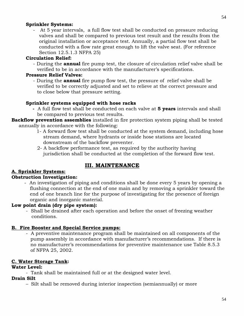
54
54
Sprinkler Systems: - At 5 year intervals, a full flow test shall be conducted on pressure reducing
valves and shall be compared to previous test result and the results from the original installation or acceptance test. Annually, a partial flow test shall be conducted with a flow rate great enough to lift the valve seat. (For reference Section 12.5.1.3 NFPA 25)
Circulation Relief: - During the annual fire pump test, the closure of circulation relief valve shall be
verified to be in accordance with the manufacturer’s specifications. Pressure Relief Valves:
- During the annual fire pump flow test, the pressure of relief valve shall be verified to be correctly adjusted and set to relieve at the correct pressure and to close below that pressure setting.
Sprinkler systems equipped with hose racks
- A full flow test shall be conducted on each valve at 5 years intervals and shall be compared to previous test results.
Backflow prevention assemblies installed in fire protection system piping shall be tested annually in accordance with the following: 1- A forward flow test shall be conducted at the system demand, including hose stream demand, where hydrants or inside hose stations are located downstream of the backflow preventer. 2- A backflow performance test, as required by the authority having jurisdiction shall be conducted at the completion of the forward flow test.
III. MAINTENANCE A. Sprinkler Systems: Obstruction Investigation:
- An investigation of piping and conditions shall be done every 5 years by opening a flushing connection at the end of one main and by removing a sprinkler toward the end of one branch line for the purpose of investigating for the presence of foreign organic and inorganic material. Low point drain (dry pipe system):
- Shall be drained after each operation and before the onset of freezing weather conditions.
B. Fire Booster and Special Service pumps:
- A preventive maintenance program shall be maintained on all components of the pump assembly in accordance with manufacturer’s recommendations. If there is no manufacturer’s recommendations for preventive maintenance use Table 8.5.3 of NFPA 25, 2002.
C. Water Storage Tank: Water Level:
- Tank shall be maintained full or at the designed water level. Drain Silt
– Silt shall be removed during interior inspection (semiannually) or more

55
55
frequently as needed to avoid accumulation to the level of the tank outlet. Embankment-Supported Coated Fabric (ESCF) Suction Tanks: – The maintenance of ESCF tanks shall be done according the tank manufacturer manual. D. Valve and Valve Component: Control Valves:
– The operating stems of outside screw and yoke valves shall be lubricated annually. The valve then shall be completely closed and reopened to test its operation and distribute the lubricant. Preaction/Deluge Valves
– During the annual trip test, the interior of the preaction or deluge valve shall be cleaned thoroughly and the parts replaced or repaired as necessary. Dry Pipe Valves / Quick – Opening Devices
– During the annual trip test, the interior of the preaction or deluge valve shall be cleaned thoroughly and the parts replaced or repaired as necessary.
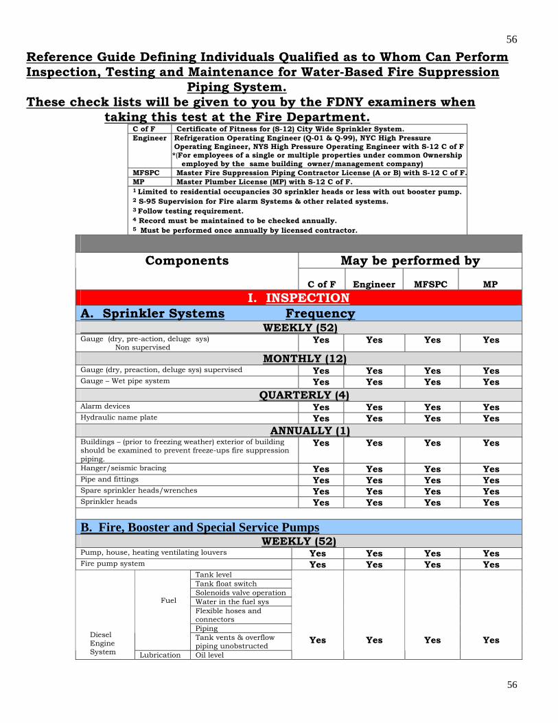
56
56
Reference Guide Defining Individuals Qualified as to Whom Can Perform Inspection, Testing and Maintenance for Water-Based Fire Suppression Piping System. These check lists will be given to you by the FDNY examiners when taking this test at the Fire Department.
C of F Certificate of Fitness for (S-12) City Wide Sprinkler System. Engineer Refrigeration Operating Engineer (Q-01 & Q-99), NYC High Pressure
Operating Engineer, NYS High Pressure Operating Engineer with S-12 C of F *(For employees of a single or multiple properties under common 0wnership employed by the same building owner/management company)
MFSPC Master Fire Suppression Piping Contractor License (A or B) with S-12 C of F.MP Master Plumber License (MP) with S-12 C of F. 1 Limited to residential occupancies 30 sprinkler heads or less with out booster pump. 2 S-95 Supervision for Fire alarm Systems & other related systems. 3 Follow testing requirement. 4 Record must be maintained to be checked annually. 5 Must be performed once annually by licensed contractor.
May be performed by Components
C of F
Engineer
MFSPC
MP
I. INSPECTION
A. Sprinkler Systems Frequency WEEKLY (52) Gauge (dry, pre-action, deluge sys) Non supervised
Yes Yes Yes Yes
MONTHLY (12) Gauge (dry, preaction, deluge sys) supervised Yes Yes Yes Yes Gauge – Wet pipe system Yes Yes Yes Yes QUARTERLY (4) Alarm devices Yes Yes Yes Yes Hydraulic name plate Yes Yes Yes Yes ANNUALLY (1) Buildings – (prior to freezing weather) exterior of building should be examined to prevent freeze-ups fire suppression piping.
Yes Yes Yes Yes
Hanger/seismic bracing Yes Yes Yes Yes Pipe and fittings Yes Yes Yes Yes Spare sprinkler heads/wrenches Yes Yes Yes Yes Sprinkler heads Yes Yes Yes Yes
B. Fire, Booster and Special Service Pumps WEEKLY (52)
Pump, house, heating ventilating louvers Yes Yes Yes Yes Fire pump system Yes Yes Yes Yes
Tank level Tank float switch Solenoids valve operation Water in the fuel sys Flexible hoses and connectors Piping
Fuel
Tank vents & overflow piping unobstructed
Diesel Engine System Lubrication Oil level
Yes
Yes
Yes
Yes

57
57
Lube oil heater system
Crankcase breather
Level Adequate cooling water to heat exchanger Water pumps Cond. Of flexible hoses & connection
Cooling system
Jacket water heater Leakage Drain condensate trap Hangers & supports
Exhaust system
Flexible exhaust section Electrolyte level Terminals clean and tight
Battery system
Equalize charge General inspection Operation of safeties & alarms
Electrical system
Circuit breakers or fuses
MONTHLY (12) Circuit breakers or fuses Yes Yes Yes Yes Diesel Engine System
Charger & charge rate Yes Yes Yes Yes QUARTERLY (4)
Exhaust system
Insulation & fire hazards Diesel Engine System Electrical
system Wire chafing where
subject to movement
Yes Yes Yes Yes
SEMIANNUALLY (2) Diesel Engine System
Electrical system
Operation of safeties and alarms
Yes Yes Yes Yes
ANNUALLY (1) Check accuracy of pressure gauges and sensors Check pump shaft endplay, coupling alignment
Fire pump system
Wet pit suction screens
Yes Yes Yes Yes
Diesel Engine System
Cooling sys
Inspect duct work, clean louvers (combustion air)
Yes Yes Yes Yes
Inspect emergency manual starting means ( without power) Tighten electrical connections as necessary Lubricate mechanical moving parts (excluding starters & relays
Electrical
system 2
Calibrate pressure switch settings
Yes Yes Yes Yes
C. Water Storage Tank DAILY (365)
Water temperature – without low temperature alarms (cold weather)
Yes Yes Yes Yes
Heating System – without low temperature alarms (cold weather)
Yes Yes Yes Yes
WEEKLY (52) Water temperature - with low temperature alarms (cold weather)
Yes Yes Yes Yes
Heating system – with low temperature alarms (cold weather)
Yes Yes Yes Yes
MONTHLY (12)
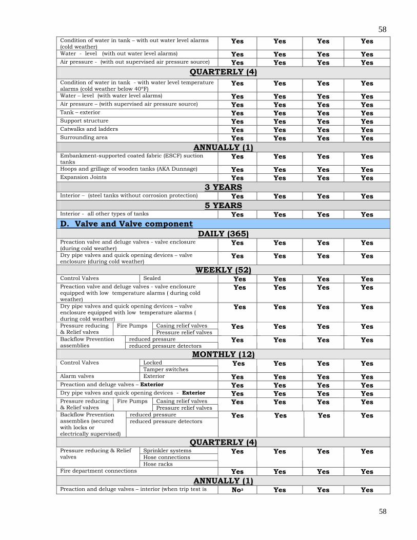
58
58
Condition of water in tank – with out water level alarms (cold weather)
Yes Yes Yes Yes
Water - level (with out water level alarms) Yes Yes Yes Yes Air pressure - (with out supervised air pressure source) Yes Yes Yes Yes
QUARTERLY (4) Condition of water in tank - with water level temperature alarms (cold weather below 40ºF)
Yes Yes Yes Yes
Water – level (with water level alarms) Yes Yes Yes Yes Air pressure – (with supervised air pressure source) Yes Yes Yes Yes Tank – exterior Yes Yes Yes Yes Support structure Yes Yes Yes Yes Catwalks and ladders Yes Yes Yes Yes Surrounding area Yes Yes Yes Yes
ANNUALLY (1) Embankment-supported coated fabric (ESCF) suction tanks
Yes Yes Yes Yes
Hoops and grillage of wooden tanks (AKA Dunnage) Yes Yes Yes Yes Expansion Joints Yes Yes Yes Yes
3 YEARS Interior – (steel tanks without corrosion protection) Yes Yes Yes Yes
5 YEARS Interior - all other types of tanks Yes Yes Yes Yes D. Valve and Valve component
DAILY (365) Preaction valve and deluge valves - valve enclosure (during cold weather)
Yes Yes Yes Yes
Dry pipe valves and quick opening devices – valve enclosure (during cold weather)
Yes Yes Yes Yes
WEEKLY (52) Control Valves Sealed Yes Yes Yes Yes Preaction valve and deluge valves - valve enclosure equipped with low temperature alarms ( during cold weather)
Yes Yes Yes Yes
Dry pipe valves and quick opening devices – valve enclosure equipped with low temperature alarms ( during cold weather)
Yes
Yes Yes Yes
Casing relief valves Pressure reducing & Relief valves
Fire Pumps Pressure relief valves
Yes Yes Yes Yes
reduced pressure Backflow Prevention assemblies reduced pressure detectors
Yes Yes Yes Yes
MONTHLY (12) Locked Control Valves Tamper switches
Yes Yes Yes Yes
Alarm valves Exterior Yes Yes Yes Yes Preaction and deluge valves – Exterior Yes Yes Yes Yes Dry pipe valves and quick opening devices - Exterior Yes Yes Yes Yes
Casing relief valves Pressure reducing & Relief valves
Fire Pumps Pressure relief valves
Yes Yes Yes Yes
reduced pressure Backflow Prevention assemblies (secured with locks or electrically supervised)
reduced pressure detectors Yes Yes Yes Yes
QUARTERLY (4) Sprinkler systems Hose connections
Pressure reducing & Relief valves
Hose racks
Yes Yes Yes Yes
Fire department connections Yes Yes Yes Yes ANNUALLY (1)
Preaction and deluge valves – interior (when trip test is No3 Yes Yes Yes
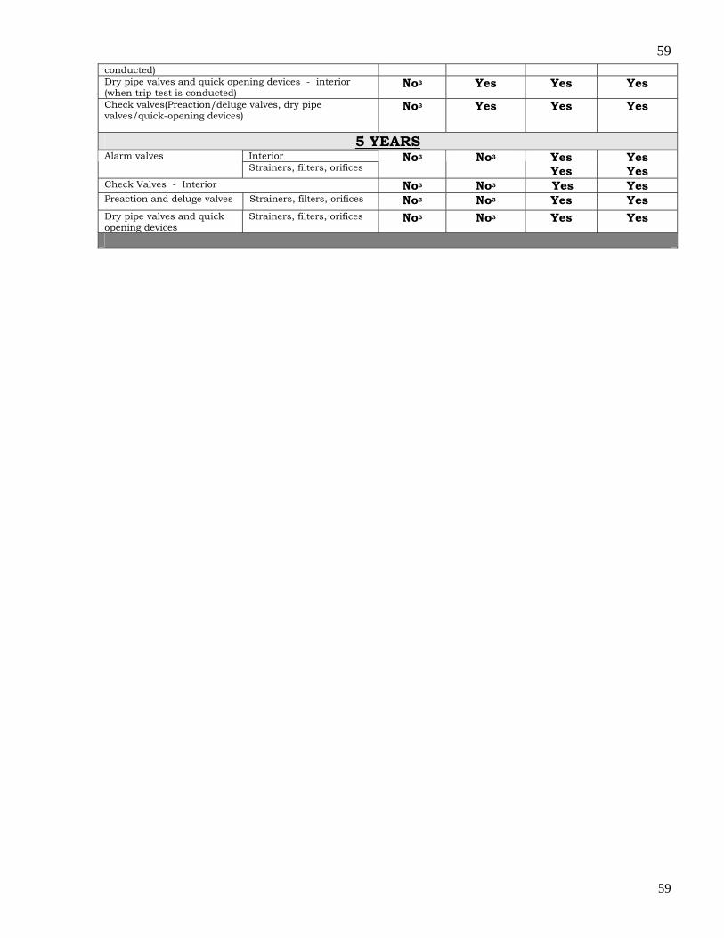
59
59
conducted) Dry pipe valves and quick opening devices - interior (when trip test is conducted)
No3 Yes Yes Yes
Check valves(Preaction/deluge valves, dry pipe valves/quick-opening devices)
No3 Yes Yes Yes
5 YEARS Interior Alarm valves Strainers, filters, orifices
No3 No3 Yes Yes
Yes Yes
Check Valves - Interior No3 No3 Yes Yes Preaction and deluge valves Strainers, filters, orifices No3 No3 Yes Yes Dry pipe valves and quick opening devices
Strainers, filters, orifices No3 No3 Yes Yes

60
60
Reference Guide Defining Individuals Qualified as to Whom Can Perform Inspection, Testing and Maintenance for Water-Based Fire Suppression Piping System These Reference Guide will be given to you by the FDNY examiners when taking this test at the Fire Department.
C of F Certificate of Fitness for (S-12) City wide Sprinkler System. Engineer Refrigeration Operating Engineer (Q-01 & Q-99), NYC High Pressure Operating
Engineer, NYS High Pressure Operating Engineer with S-12 C of F *(For employees of a single or multiple properties under common 0wnership employed by the same building owner/management company)
MFSPC Master Fire Suppression Piping Contractor License with S-12 C of F. MP Master Plumber License (MP) with S-12 C of F. 1 Limited to residential occupancies 30 sprinkler heads or less with out booster pump. 2 S-95 Supervision for Fire alarm Systems & other related systems. 3 Follow testing requirement. 4 Record must be maintained to be checked annually. 5 Must be performed once annually by licensed contractor.
May be performed by Components
C of F Engineer MFSPC MP1
II. TEST
A. Sprinkler Systems QUARTERLY (4)
water motor gong Yes Yes Yes Yes1 Alarm Devices
pressure switch type Yes Yes Yes Yes1 SEMIANNUALLY (2)
Alarm Devices (Vane type water flow devices) Yes Yes Yes Yes1 ANNUALLY (1)
Antifreeze solution No No Yes Yes1 5 YEARS
Gauges - Remove & send for calibration test or replace as required
No Yes4 Yes Yes1 Sprinklers - Remove send for extra high temperature test and replace as required
No No Yes Yes1
10 years & every 10 yrs thereafter Sprinklers - Dry type No No Yes Yes1
20 years & every 10 yrs thereafter Sprinklers – fast response and residential No No Yes Yes1
50 years & every 10 years after Sprinklers (Standard Response) No No Yes Yes1 B. Fire, Booster and Special Service Pumps
WEEKLY (52) Pump operation - No-flow condition No Yes Yes Yes1 Fire pump – Electric pump (minimum of 10 minutes) No Yes Yes Yes1
tank float switch Diesel Engine system Solenoids valve operation
No Yes Yes Yes1
MONTHLY (1) Electrical system 2 Isolating switch & circuit breaker
Battery system Specific gravity or state of charge No
Yes4
Yes Yes1
SEMIANNUALLY (2) Electrical system 2 Operating manual starting means
(electrical) No Yes4 Yes Yes1

61
61
Cooling system
Antifreeze protection level Tank float switch fuel Solenoids valve operation
Diesel Engine System
Electrical system
Operation of safeties and alarms
No
Yes4
Yes Yes1
ANNUALLY (1) Pump operation - Flow condition No No Yes No
Trip circuit breaker( if mechanism provided)
Electrical system 2
Operate emergency manual starting means( without power)
No
No
Yes No
Exhaust system Excessive back pressure No No Yes No Diesel Engine System
Tank vents and overflow piping unobstructed
No No Yes No
C. Water Storage Tank
MONTHLY (12) Temperature alarms (cold weather) No Yes5 Yes Yes1 High temperature limit switches (cold weather) No Yes5 Yes Yes1
SEMIANNUALLY (2) Water level alarms No Yes5 Yes Yes1 5 YEARS Level indicators No Yes5 Yes Yes1 Pressure gauges No Yes5 Yes Yes1 D. Valve and Valve Component
QUARTERLY (4) Main drain No Yes5 Yes Yes1 Water-Flow Alarms No Yes5 Yes Yes1
Priming water Preaction and deluge valves Low air pressure alarm
No Yes5 Yes Yes1 Priming water Low air pressure alarm
Dry pipe valves and Quick Opening devices
Quick-opening devices
No Yes5 Yes Yes1
SEMIANNUALLY (2) Control Valves Supervisory No Yes5 Yes Yes1
ANNUALLY (1) Main drain No No Yes Yes1 Preaction and deluge valves Full flow No No Yes Yes1
Dry pipe valves and Quick Opening devices Trip test No No Yes Yes1 Position Control Valves Operation
No No Yes Yes1 Circulation relief Pressure reducing and Relief valves Pressure relief valves
No No Yes Yes1 Backflow prevention Assemblies No No Yes Yes1
3 YEARS Dry pipe valves and Quick Opening devices
Full flow trip test No No Yes Yes1
5 YEARS Sprinkler systems Hose connections
Pressure reducing & Relief valves
Hose racks
No No Yes Yes1
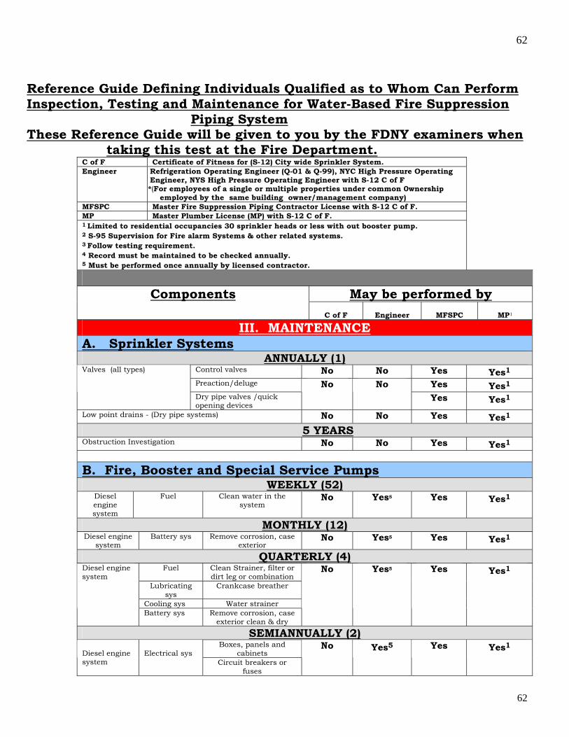
62
62
Reference Guide Defining Individuals Qualified as to Whom Can Perform Inspection, Testing and Maintenance for Water-Based Fire Suppression Piping System These Reference Guide will be given to you by the FDNY examiners when taking this test at the Fire Department.
C of F Certificate of Fitness for (S-12) City wide Sprinkler System. Engineer Refrigeration Operating Engineer (Q-01 & Q-99), NYC High Pressure Operating
Engineer, NYS High Pressure Operating Engineer with S-12 C of F *(For employees of a single or multiple properties under common 0wnership employed by the same building owner/management company)
MFSPC Master Fire Suppression Piping Contractor License with S-12 C of F. MP Master Plumber License (MP) with S-12 C of F. 1 Limited to residential occupancies 30 sprinkler heads or less with out booster pump. 2 S-95 Supervision for Fire alarm Systems & other related systems. 3 Follow testing requirement. 4 Record must be maintained to be checked annually. 5 Must be performed once annually by licensed contractor.
May be performed by Components
C of F
Engineer MFSPC
MP1
III. MAINTENANCE A. Sprinkler Systems
ANNUALLY (1) Control valves No No Yes Yes1 Preaction/deluge Yes Yes1
Valves (all types)
Dry pipe valves /quick opening devices
No No Yes Yes1
Low point drains - (Dry pipe systems) No No Yes Yes1 5 YEARS Obstruction Investigation No No Yes Yes1
B. Fire, Booster and Special Service Pumps
WEEKLY (52) Diesel engine system
Fuel Clean water in the system
No Yes5 Yes Yes1
MONTHLY (12) Diesel engine
system Battery sys Remove corrosion, case
exterior No Yes5 Yes Yes1
QUARTERLY (4) Fuel Clean Strainer, filter or
dirt leg or combination Lubricating
sys Crankcase breather
Cooling sys Water strainer
Diesel engine system
Battery sys Remove corrosion, case exterior clean & dry
No Yes5 Yes Yes1
SEMIANNUALLY (2) Boxes, panels and
cabinets Diesel engine system
Electrical sys
Circuit breakers or fuses
No Yes5 Yes Yes1

63
63
ANNUALLY (1) Hydraulic No No Yes Yes1
Lubricate pump bearings Check accuracy of pressure gauges &
sensors
Pump system
Wet pit suction screens (after each pump opera.)
No No Yes Yes1
Lubricate coupling Mechanical transmission Lubricate right angle gear drive
No No Yes Yes1 Electrical system
Grease motor bearings No No Yes Yes1 Controller, various components No No Yes Yes1 Motor No No Yes Yes1
Inspect duct work clean louvers Rod out heat exchanger
Cooling sys
Antifreeze Oil change Lubrication sys Oil filters
Diesel engine system various components
Exhaust sys Excessive back pressure
No No Yes Yes1
C. Water Storage Tank Water level as required Yes Yes Yes Yes1
SEMIANNUALLY (2) Drain silt No Yes5 Yes Yes1
ANNUALLY (1) Embankment-supported coated fabric (ESCF) suction tanks
No No Yes Yes1
D. Valve and Valve Component
ANNUALLY (1) Control valves No No Yes Yes1 Preaction and Deluge Valves No No Yes Yes1 Dry Pipe Valves and Quick-Opening Devices No No Yes Yes1 Electrical release component for Preaction/deluge system {i.e. smoke detectors) 2
No No Yes Yes1
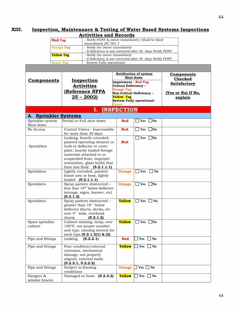
64
64
XIII. Inspection, Maintenance & Testing of Water Based Systems Inspections Activities and Records
Red Tag - Notify FDNY & owner immediately ( Shall be fixed Immediately )FC 901.7
Orange Tag - Notify the owner immediately - If deficiency is not corrected after 30 days Notify FDNY
Yellow Tag - Notify the owner immediately - if deficiency is not corrected after 30 days Notify FDNY
Green Tag System Fully operational
Notification of system
Shut down
Components
Inspection Activities
(Reference NFPA 25 – 2002)
Impairment - Red Tag Critical Deficiency – Orange Tag Non-Critical Deficiency – Yellow Tag System Fully operational- Green
Components Checked
Satisfactory
(Yes or No) If No, explain
I. INSPECTION A. Sprinkler Systems Sprinkler system Shut down
Partial or Full shut down Red Yes No
No Access Control Valves - Inaccessible for more than 30 days
Red Yes No
Sprinklers
Leaking, heavily corroded, painted operating element or bulb or deflector or cover plate, heavily loaded foreign materials attached to or suspended from, improper orientation, glass bulbs that have lost fluid (5.2.1.1.1)
Red
Yes No
Sprinklers Lightly corroded, painted frame arm or boss, lightly loaded (5.2.1.1.1)
Orange Yes No
Sprinklers Spray pattern obstructed – less that 18’” below deflector (storage, signs, banner, etc) (5.2.1.2)
Orange Yes No
Sprinklers Spray pattern obstructed – greater than 18’’ below deflector (ducts, decks, etc over 4’’ wide, overhead doors) (5.2.1.2)
Yellow Yes No
Spare sprinkler cabinet
Cabinet missing, temp, over 100ºF, not proper number and type, missing wrench for each type (5.2.1.3(1) & (2)
Yellow Yes No
Pipe and fittings Leaking (5.2.2.1) Red Yes No
Pipe and fittings Poor condition/external corrosion, mechanical damage, not properly aligned, external loads (5.2.2.1, 5.2.2.2)
Yellow Yes No
Pipe and fittings Subject to freezing conditions
Orange Yes No
Hangers & seismic braces
Damaged or loose (5.2.3.2) Yellow Yes No
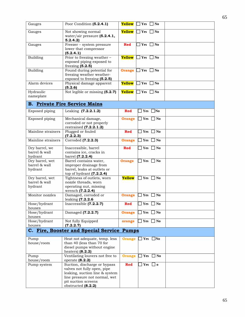
65
65
Gauges Poor Condition (5.2.4.1) Yellow Yes No
Gauges Not showing normal water/air pressure (5.2.4.1, 5.2.4.2)
Yellow Yes No
Gauges Freezer – system pressure lower that compressor (5.2.4.1)
Red Yes No
Building Prior to freezing weather – exposed piping exposed to freezing (5.2.5)
Yellow Yes No
Building Found during potential for freezing weather weather-exposed to freezing (5.2.5)
Orange Yes No
Alarm devices Physical damage apparent (5.2.6)
Yellow Yes No
Hydraulic nameplate
Not legible or missing (5.2.7) Yellow Yes No
B. Private Fire Service Mains Exposed piping Leaking (7.2.2.1.2) Red Yes No
Exposed piping Mechanical damage, corroded or not properly restrained (7.2.2.1.2)
Orange Yes No
Mainline strainers Plugged or fouled (7.2.2.3)
Red Yes No
Mainline strainers Corroded (7.2.2.3) Orange Yes No
Dry barrel, we barrel & wall hydrant
Inaccessible, barrel contains ice, cracks in barrel (7.2.2.4)
Red Yes No
Dry barrel, wet barrel & wall hydrant
Barrel contains water, improper drainage from barrel, leaks at outlets or top of hydrant (7.2.2.4)
Orange Yes No
Dry barrel, wet barrel & wall hydrant
Tightness of outlets, worn nozzle threads, worn operating nut, missing wrench (7.2.2.4)
Yellow Yes No
Monitor nozzles Damaged, corroded or leaking (7.2.2.6
Orange Yes No
Hose/hydrant houses
Inaccessible (7.2.2.7) Red Yes No
Hose/hydrant houses
Damaged (7.2.2.7) Orange Yes No
Hose/hydrant houses
Not fully Equipped (7.2.2.7)
orange Yes No
C. Fire, Booster and Special Service Pumps
Pump house/room
Heat not adequate, temp. less than 40 (less than 70 for diesel pumps without engine heaters) (8.2.2)
Orange Yes No
Pump house/room
Ventilating louvers not free to operate (8.2.2)
Orange Yes No
Pump system Suction, discharge or bypass valves not fully open, pipe leaking, suction line & system line pressure not normal, wet pit suction screens obstructed (8.2.2)
Red Yes o
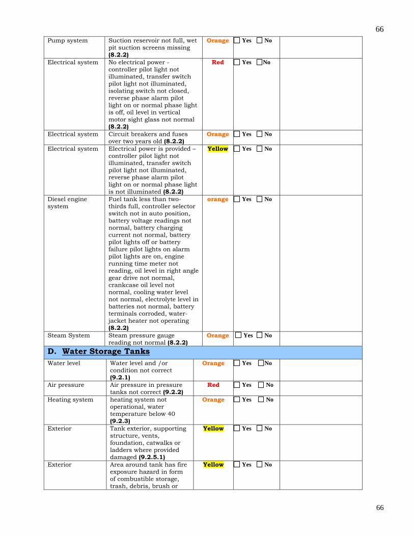
66
66
Pump system Suction reservoir not full, wet pit suction screens missing (8.2.2)
Orange Yes No
Electrical system No electrical power - controller pilot light not illuminated, transfer switch pilot light not illuminated, isolating switch not closed, reverse phase alarm pilot light on or normal phase light is off, oil level in vertical motor sight glass not normal (8.2.2)
Red Yes No
Electrical system Circuit breakers and fuses over two years old (8.2.2)
Orange Yes No
Electrical system Electrical power is provided – controller pilot light not illuminated, transfer switch pilot light not illuminated, reverse phase alarm pilot light on or normal phase light is not illuminated (8.2.2)
Yellow Yes No
Diesel engine system
Fuel tank less than two-thirds full, controller selector switch not in auto position, battery voltage readings not normal, battery charging current not normal, battery pilot lights off or battery failure pilot lights on alarm pilot lights are on, engine running time meter not reading, oil level in right angle gear drive not normal, crankcase oil level not normal, cooling water level not normal, electrolyte level in batteries not normal, battery terminals corroded, water-jacket heater not operating (8.2.2)
orange Yes No
Steam System Steam pressure gauge reading not normal (8.2.2)
Orange Yes No
D. Water Storage Tanks Water level Water level and /or
condition not correct (9.2.1)
Orange Yes No
Air pressure Air pressure in pressure tanks not correct (9.2.2)
Red Yes No
Heating system heating system not operational, water temperature below 40 (9.2.3)
Orange Yes No
Exterior Tank exterior, supporting structure, vents, foundation, catwalks or ladders where provided damaged (9.2.5.1)
Yellow Yes No
Exterior Area around tank has fire exposure hazard in form of combustible storage, trash, debris, brush or
Yellow Yes No
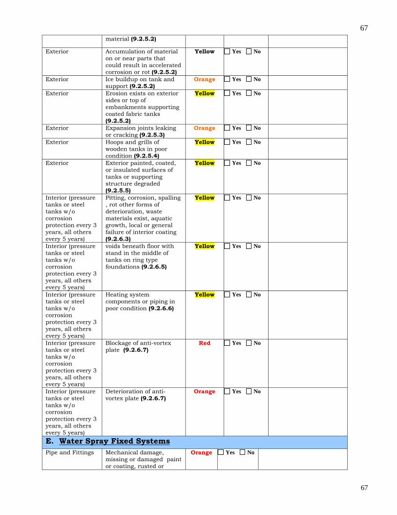
67
67
material (9.2.5.2)
Exterior Accumulation of material on or near parts that could result in accelerated corrosion or rot (9.2.5.2)
Yellow Yes No
Exterior Ice buildup on tank and support (9.2.5.2)
Orange Yes No
Exterior Erosion exists on exterior sides or top of embankments supporting coated fabric tanks (9.2.5.2)
Yellow Yes No
Exterior Expansion joints leaking or cracking (9.2.5.3)
Orange Yes No
Exterior Hoops and grills of wooden tanks in poor condition (9.2.5.4)
Yellow Yes No
Exterior Exterior painted, coated, or insulated surfaces of tanks or supporting structure degraded (9.2.5.5)
Yellow Yes No
Interior (pressure tanks or steel tanks w/o corrosion protection every 3 years, all others every 5 years)
Pitting, corrosion, spalling , rot other forms of deterioration, waste materials exist, aquatic growth, local or general failure of interior coating (9.2.6.3)
Yellow Yes No
Interior (pressure tanks or steel tanks w/o corrosion protection every 3 years, all others every 5 years)
voids beneath floor with stand in the middle of tanks on ring type foundations (9.2.6.5)
Yellow Yes No
Interior (pressure tanks or steel tanks w/o corrosion protection every 3 years, all others every 5 years)
Heating system components or piping in poor condition (9.2.6.6)
Yellow Yes No
Interior (pressure tanks or steel tanks w/o corrosion protection every 3 years, all others every 5 years)
Blockage of anti-vortex plate (9.2.6.7)
Red Yes No
Interior (pressure tanks or steel tanks w/o corrosion protection every 3 years, all others every 5 years)
Deterioration of anti-vortex plate (9.2.6.7)
Orange Yes No
E. Water Spray Fixed Systems
Pipe and Fittings Mechanical damage, missing or damaged paint or coating, rusted or
Orange Yes No
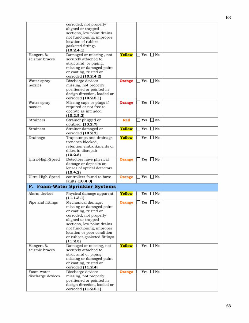
68
68
corroded, not properly aligned or trapped sections, low point drains not functioning, improper location of rubber-gasketed fittings (10.2.4.1)
Hangers & seismic braces
Damaged or missing , not securely attached to structural or piping, missing or damaged paint or coating, rusted or corroded (10.2.4.2)
Yellow Yes No
Water spray nozzles
Discharge devices missing, not properly positioned or pointed in design direction, loaded or corroded (10.2.5.1)
Orange Yes No
Water spray nozzles
Missing caps or plugs if required or not free to operate as intended (10.2.5.2)
Orange Yes No
Strainers Strainer plugged or doubled (10.2.7)
Red Yes No
Strainers Strainer damaged or corroded (10.2.7)
Yellow Yes No
Drainage Trap sumps and drainage trenches blocked, retention embankments or dikes in disrepair (10.2.8)
Yellow Yes No
Ultra-High-Speed Detectors have physical damage or deposits on lenses of optical detectors (10.4.2)
Orange Yes No
Ultra-High-Speed controllers found to have faults (10.4.3)
Orange Yes No
F. Foam-Water Sprinkler Systems
Alarm devices Physical damage apparent (11.1.3.1)
Yellow Yes No
Pipe and fittings Mechanical damage, missing or damaged paint or coating, rusted or corroded, not properly aligned or trapped sections, low point drains not functioning, improper location or poor condition or rubber-gasketed fittings (11.2.3)
Orange Yes No
Hangers & seismic braces
Damaged or missing, not securely attached to structural or piping, missing or damaged paint or coating, rusted or corroded (11.2.4)
Yellow Yes No
Foam-water discharge devices
Discharge devices missing, not properly positioned or pointed in design direction, loaded or corroded (11.2.5.1)
Orange Yes No

69
69
Foam-water discharge devices
Not free to operate as intended (11.2.5.2)
Orange Yes No
Foam-water discharge devices
Missing caps or plugs if required (11.2.5.2)
Yellow Yes No
Foam-water discharge devices
Discharge devices not listed for use with foam concentrate (11.2.5.4)
Orange Yes No
Foam Concentrate strainers
Blow-down vane open or not plugged (11.2.7.2)
Orange Yes No
Drainage Trap sumps and drainage trenches blocked, retention embankments or dikes in disrepair (11.2.8)
Yellow Yes No
Proportioning systems (all)
Proportioning system valves not in correct open/closed position in accordance with specified operating conditions (11.2.9.3)
Red Yes No
Proportioning systems (all)
Concentrate tank does not have correct quantity required by original design (11.2.9.4)
Orange Yes No
Standard pressure proportioner
Automatic drains (ball drip valves) not free or open, external corrosion on foam concentrate tanks (11.2.9.5.1)
Yellow Yes No
Bladder tank proportioned
Water control valve to foam concentrate in “ closed” position (11.2.9.5.2)
Red Yes No
Bladder tank proportioned
Foam in water surrounding bladder (11.2.9.5.2)
Orange Yes No
Bladder tank proportioned
External corrosion on foam concentrate tank (11.2.9.5.2)
Yellow Yes No
Line proportioner Strainer damaged, corroded, plugged or fouled, pressure vacuum vent not operating freely (11.2.9.5.3)
Orange Yes No
Line proportioner External corrosion on foam concentrate tank (11.2.9.5.3)
Yellow Yes No
Standard balanced pressure proportioner
Sensing line valves not open, no power to foam liquid pump (11.2.9.5.4)
Red Yes No
Standard balanced pressure proportioner
Strainer damaged, corroded, plugged of fouled, pressure vacuum vent not operating freely, gauges damaged or not showing proper pressures (11.2.9.5.3)
Orange Yes No
In-Line balanced pressure proportioer
Sensing line valves at pump unit or individual proportioner stations not open, no power to foam liquid pump (11.2.9.5.4)
Red Yes No
In-Line balanced pressure
Strainer damaged, corroded, plugged of
Orange Yes No
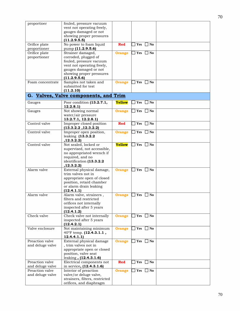
70
70
proportioer fouled, pressure vacuum vent not operating freely, gauges damaged or not showing proper pressures (11.2.9.5.5)
Orifice plate proportioner
No power to foam liquid pump (11.2.9.5.6)
Red Yes No
Orifice plate proportioner
Strainer damaged, corroded, plugged of fouled, pressure vacuum vent not operating freely, gauges damaged or not showing proper pressures (11.2.9.5.6)
Orange Yes No
Foam concentrate Samples not taken and submitted for test (11.2.10)
Orange Yes No
G. Valves, Valve components, and Trim
Gauges Poor condition (13.2.7.1, 12.2.8.1)
Yellow Yes No
Gauges Not showing normal water/air pressure 13.2.7.1, 12.2.8.1)
Orange Yes No
Control valve Improper closed position (13.3.2.2 ,12.3.2.2)
Red Yes No
Control valve Improper open position, leaking (13.3.2.2 ,12.3.2.2)
Orange Yes No
Control valve Not sealed, locked or supervised, not accessible, no appropriated wrench if required, and no identification (13.3.2.2 ,12.3.2.2)
Yellow Yes No
Alarm valve External physical damage, trim valves not in appropriate open of closed position, retard chamber or alarm drain leaking (12.4.1.1)
Orange Yes No
Alarm valve Alarm valve, strainers , filters and restricted orifices not internally inspected after 5 years (12.4.1.2)
Orange Yes No
Check valve Check valve not internally inspected after 5 years (12.4.2.1)
Orange Yes No
Valve enclosure Not maintaining minimum 40ºF temp. (12.4.3.1.1 , 12.4.4.1.1)
Orange Yes No
Preaction valve and deluge valve
External physical damage , trim valves not in appropriate open or closed position, valve seat leaking , (12.4.3.1.6)
Orange Yes No
Preaction valve and deluge valve
Electrical components not in service, (12.4.3.1.6)
Red Yes No
Preaction valve and deluge valve
Interior of preaction valve/or deluge valve, strainers, filters, restricted orifices, and diaphragm
Orange Yes No
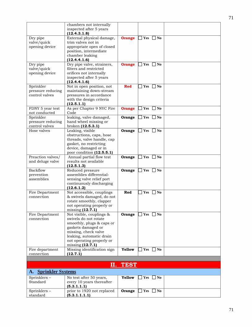
71
71
chambers not internally inspected after 5 years (12.4.3.1.8)
Dry pipe valve/quick opening device
External physical damage, trim valves not in appropriate open of closed position, intermediate chamber leaking (12.4.4.1.6)
Orange Yes No
Dry pipe valve/quick opening device
Dry pipe valve, strainers, filters and restricted orifices not internally inspected after 5 years (12.4.4.1.6)
Orange Yes No
Sprinkler pressure reducing control valves
Not in open position, not maintaining down-stream pressures in accordance with the design criteria (12.5.1.1)
Red Yes No
FDNY 5 year test not conducted
As per Chapter 9 NYC Fire Code
Orange Yes No
Sprinkler pressure reducing control valves
leaking, valve damaged, hand wheel missing or broken (12.5.3.1)
Orange Yes No
Hose valves Leaking, visible obstructions, caps, hose threads, valve handle, cap gasket, no restricting device, damaged or in poor condition (12.5.5.1)
Orange Yes No
Preaction valves/ and deluge valve
Annual partial flow test results not available (12.5.1.3)
Orange Yes No
Backflow prevention assemblies
Reduced pressure assemblies differential-sensing valve relief port continuously discharging (12.6.1.2)
Orange Yes No
Fire Department connection
Not accessible, couplings & swivels damaged, do not rotate smoothly, clapper not operating properly or missing (12.7.1)
Red Yes No
Fire Department connection
Not visible, couplings & swivels do not rotate smoothly, plugs & caps or gaskets damaged or missing, check valve leaking, automatic drain not operating properly or missing (12.7.1)
Orange Yes No
Fire department connection
Missing identification sign (12.7.1)
Yellow Yes No
II. TEST A. Sprinkler Systems Sprinklers – Standard
No test after 50 years, every 10 years thereafter (5.3.1.1.1)
Yellow Yes No
Sprinklers – standard
prior to 1920 not replaced (5.3.1.1.1.1)
Orange Yes No

72
72
Sprinklers – fast response
No test after 20 years, every 10 years thereafter (5.3.1.1.1.2)
Yellow Yes No
Sprinklers – solder-type 325 or greater
No test after 5 years, every 5 years thereafter (5.3.1.1.1.3)
Yellow Yes No
Sprinklers- standard
No test after 75 years, every 5 years thereafter (5.3.1.1.1.4)
Yellow Yes No
Sprinklers – dry type
No test after 10 years, every 10 years thereafter (5.3.1.1.1.5)
Orange Yes No
Sprinklers – subject to harsh environments
(Corrosive atmospheres, corrosive water supply, includes freezers and coolers) No test after 5 years, every 5 years thereafter (5.3.1.1.2)
Yellow Yes No
Sprinklers – solder type
(Commercial-type cooking equipment. & ventilating systems) No replacement after one year (5.4.1.9)
Orange Yes No
Sprinklers in spray coating areas
Plastic or paper bags used to protect against overspray residue, with deposits or residue accumulation (5.4.1.7.1, 5.4.1.7.2)
Red Yes No
Gauges Not replaced or calibrated in 5 years, not accurate within 3% of scale (5.3.2)
Yellow Yes No
Alarm devices Water motor and gong not functioning (5.3.3)
Orange Yes No
Alarm devices Pressure switch or vane type switch not functioning or no alarm (5.3.4)
Orange Yes No
Antifreeze systems
Specific gravity of antifreeze not correct (5.3.2)
Orange Yes No
Main drain Large drop in full flow pressure or slow return to normal static pressure. (10.3.7.1)
Red Yes No
Obstruction Investigation
No inspection of main and branch line after 5 years or inspection revealed presence of MIC, zebra mussels, rust and scale (14.2.1)
Orange Yes No
B. Private Fire Service Mains
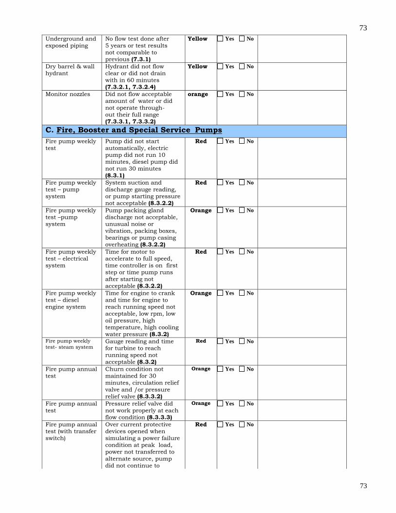
73
73
Underground and exposed piping
No flow test done after 5 years or test results not comparable to previous (7.3.1)
Yellow Yes No
Dry barrel & wall hydrant
Hydrant did not flow clear or did not drain with in 60 minutes (7.3.2.1, 7.3.2.4)
Yellow Yes No
Monitor nozzles Did not flow acceptable amount of water or did not operate through-out their full range (7.3.3.1, 7.3.3.2)
orange Yes No
C. Fire, Booster and Special Service Pumps
Fire pump weekly test
Pump did not start automatically, electric pump did not run 10 minutes, diesel pump did not run 30 minutes (8.3.1)
Red Yes No
Fire pump weekly test – pump system
System suction and discharge gauge reading, or pump starting pressure not acceptable (8.3.2.2)
Red Yes No
Fire pump weekly test –pump system
Pump packing gland discharge not acceptable, unusual noise or vibration, packing boxes, bearings or pump casing overheating (8.3.2.2)
Orange Yes No
Fire pump weekly test – electrical system
Time for motor to accelerate to full speed, time controller is on first step or time pump runs after starting not acceptable (8.3.2.2)
Red Yes No
Fire pump weekly test – diesel engine system
Time for engine to crank and time for engine to reach running speed not acceptable, low rpm, low oil pressure, high temperature, high cooling water pressure (8.3.2)
Orange Yes No
Fire pump weekly test- steam system
Gauge reading and time for turbine to reach running speed not acceptable (8.3.2)
Red Yes No
Fire pump annual test
Churn condition not maintained for 30 minutes, circulation relief valve and /or pressure relief valve (8.3.3.2)
Orange Yes No
Fire pump annual test
Pressure relief valve did not work properly at each flow condition (8.3.3.3)
Orange Yes No
Fire pump annual test (with transfer switch)
Over current protective devices opened when simulating a power failure condition at peak load, power not transferred to alternate source, pump did not continue to
Red Yes No
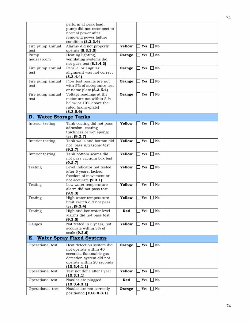
74
74
perform at peak load, pump did not reconnect to normal power after removing power failure condition (8.3.3.4)
Fire pump annual test
Alarms did not properly operate (8.3.3.5)
Yellow Yes No
Pump house/room
Heating lighting, ventilating systems did not pass test (8.3.4.3)
Orange Yes No
Fire pump annual test
Parallel or angular alignment was not correct (8.3.4.4)
Orange Yes No
Fire pump annual test
Flow test results are not with 5% of acceptance test or name plate (8.3.5.4)
Orange Yes No
Fire pump annual test
Voltage readings at the motor are not within 5 % below or 10% above the rated (name-plate) (8.3.5.6)
Orange Yes No
D. Water Storage Tanks
Interior testing Tank coating did not pass adhesion, coating thickness or wet sponge test (9.2.7)
Yellow Yes No
Interior testing Tank walls and bottom did not pass ultrasonic test (9.2.7)
Yellow Yes No
Interior testing Tank bottom seams did not pass vacuum box test (9.2.7)
Yellow Yes No
Testing Level indicator not tested after 5 years, lacked freedom of movement or not accurate (9.3.1)
Yellow Yes No
Testing Low water temperature alarm did not pass test (9.3.3)
Yellow Yes No
Testing High water temperature limit switch did not pass test (9.3.4)
Yellow Yes No
Testing High and low water level alarms did not pass test (9.3.5)
Red Yes No
Gauges Not tested in 5 years, not accurate within 3% of scale (9.3.6)
Yellow Yes No
E. Water Spray Fixed Systems
Operational test Heat detection system did not operate within 40 seconds, flammable gas detection system did not operate within 20 seconds (10.3.4.1.1)
Orange Yes No
Operational test Test not done after I year (10.3.1.1)
Yellow Yes No
Operational test Nozzles are plugged (10.3.4.3.1)
Red Yes No
Operational test Nozzles are not correctly positioned (10.3.4.3.1)
Orange Yes No
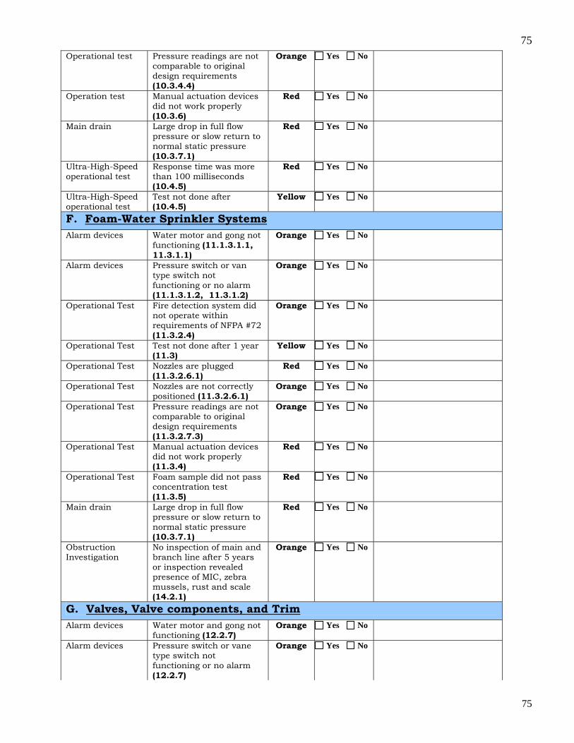
75
75
Operational test Pressure readings are not comparable to original design requirements (10.3.4.4)
Orange Yes No
Operation test Manual actuation devices did not work properly (10.3.6)
Red Yes No
Main drain Large drop in full flow pressure or slow return to normal static pressure (10.3.7.1)
Red Yes No
Ultra-High-Speed operational test
Response time was more than 100 milliseconds (10.4.5)
Red Yes No
Ultra-High-Speed operational test
Test not done after (10.4.5)
Yellow Yes No
F. Foam-Water Sprinkler Systems
Alarm devices Water motor and gong not functioning (11.1.3.1.1, 11.3.1.1)
Orange Yes No
Alarm devices Pressure switch or van type switch not functioning or no alarm (11.1.3.1.2, 11.3.1.2)
Orange Yes No
Operational Test Fire detection system did not operate within requirements of NFPA #72 (11.3.2.4)
Orange Yes No
Operational Test Test not done after 1 year (11.3)
Yellow Yes No
Operational Test Nozzles are plugged (11.3.2.6.1)
Red Yes No
Operational Test Nozzles are not correctly positioned (11.3.2.6.1)
Orange Yes No
Operational Test Pressure readings are not comparable to original design requirements (11.3.2.7.3)
Orange Yes No
Operational Test Manual actuation devices did not work properly (11.3.4)
Red Yes No
Operational Test Foam sample did not pass concentration test (11.3.5)
Red Yes No
Main drain Large drop in full flow pressure or slow return to normal static pressure (10.3.7.1)
Red Yes No
Obstruction Investigation
No inspection of main and branch line after 5 years or inspection revealed presence of MIC, zebra mussels, rust and scale (14.2.1)
Orange Yes No
G. Valves, Valve components, and Trim
Alarm devices Water motor and gong not functioning (12.2.7)
Orange Yes No
Alarm devices Pressure switch or vane type switch not functioning or no alarm (12.2.7)
Orange Yes No
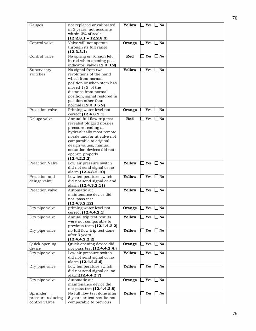
76
76
Gauges not replaced or calibrated in 5 years, not accurate within 3% of scale (12.2.8.1 – 12.2.8.3)
Yellow Yes No
Control valve Valve will not operate through its full range (12.3.3.1)
Orange Yes No
Control valve No spring or Torsion felt in rod when opening post indicator valve (12.3.3.2)
Red Yes No
Supervisory switches
No signal from two revolutions of the hand wheel from normal position or when stem has moved 1/5 of the distance from normal position, signal restored in position other than normal (12.3.3.5.2)
Yellow Yes No
Preaction valve Priming water level not correct (12.4.3.2.1)
Orange Yes No
Deluge valve Annual full flow trip test revealed plugged nozzles, pressure reading at hydraulically most remote nozzle and/or at valve not comparable to original design values, manual actuation devices did not operate properly (12.4.2.2.3)
Red Yes No
Preaction Valve Low air pressure switch did not send signal or no alarm (12.4.3.2.10)
Yellow Yes No
Preaction and deluge valve
Low temperature switch did not send signal or and alarm (12.4.3.2.11)
Yellow Yes No
Preaction valve Automatic air maintenance device did not pass test (12.4.3.2.12)
Yellow Yes No
Dry pipe valve priming water level not correct (12.4.4.2.1)
Orange Yes No
Dry pipe valve Annual trip test results were not comparable to previous tests (12.4.4.2.2)
Yellow Yes No
Dry pipe valve no full flow trip test done after 3 years (12.4.4.2.2.2)
Yellow Yes No
Quick opening device
Quick opening device did not pass test (12.4.4.2.4.)
Orange Yes No
Dry pipe valve Low air pressure switch did not send signal or no alarm (12.4.4.2.6)
Yellow Yes No
Dry pipe valve Low temperature switch did not send signal or no alarm(12.4.4.2.7)
Yellow Yes No
Dry pipe valve Automatic air maintenance device did not pass test (12.4.4.2.8)
Orange Yes No
Sprinkler pressure reducing control valves
No full flow test done after 5 years or test results not comparable to previous
Yellow Yes No
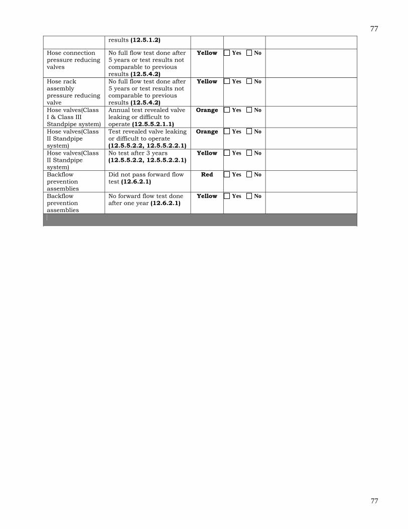
77
77
results (12.5.1.2)
Hose connection pressure reducing valves
No full flow test done after 5 years or test results not comparable to previous results (12.5.4.2)
Yellow Yes No
Hose rack assembly pressure reducing valve
No full flow test done after 5 years or test results not comparable to previous results (12.5.4.2)
Yellow Yes No
Hose valves(Class I & Class III Standpipe system)
Annual test revealed valve leaking or difficult to operate (12.5.5.2.1.1)
Orange Yes No
Hose valves(Class II Standpipe system)
Test revealed valve leaking or difficult to operate (12.5.5.2.2, 12.5.5.2.2.1)
Orange Yes No
Hose valves(Class II Standpipe system)
No test after 3 years (12.5.5.2.2, 12.5.5.2.2.1)
Yellow Yes No
Backflow prevention assemblies
Did not pass forward flow test (12.6.2.1)
Red Yes No
Backflow prevention assemblies
No forward flow test done after one year (12.6.2.1)
Yellow Yes No

78
78
XIV. LOCAL LAW 58 of 2009___________________________________________ Fire Suppression Piping Components to be identified as required by Local 58/2009 NOTE: Only existing visible piping shall be identified as required. When ceilings are removed during renovations, any existing visible system piping shall be identified and painted. Standpipe and Sprinkler Feed Mains - The portion of the standpipe or sprinkler system piping that supplies water to one or more standpipe or sprinkler risers. Standpipe and Sprinkler Cross Connections - The portion of the standpipe or sprinkler system that interconnects the feed mains and risers to the fire department connections. Standpipe and Sprinkler Risers - The vertical portion of the system piping that delivers the water supply for hose connections, and sprinklers on stand alone as well as combined systems, vertically from floor to floor. Fire Department Connections - The portion of the standpipe or sprinkler system that is connected to the fire department pumper connection and supplies the standpipe and sprinkler feed mains, cross connections, and risers. All handles of Indicating Valves - These handles control controlling the water supplies to the standpipe and sprinkler systems. Street water supply - The portion of system piping connected to the discharge of the water meter to the main sprinkler control valves. All pipe material identification information, if present, shall not be painted. Fire Suppression Piping Components not required to be identified as required by Local 58/2009. Fire Department Hose valve bodies and handles, indicating control valve bodies, check valves, jockey pump control valves, trim, test, and drain valve handles. Standpipe Branch Piping - The portion of the piping system connecting one or more hose valve stations. Sprinkler Cross Mains - The portion of the piping system connecting supplying the branch lines either directly or through risers. Sprinkler Feed Mains - The portion of the piping system downstream of a sectional or floor control valve supplying cross mains. Sprinkler Branch Piping - The portion of the piping system to which the sprinkler heads or nozzles are directly connected to. For more info go to the attached URL (NYC Building website Local law 58/2009) http://www.nyc.gov/html/dob/downloads/pdf/ll58of2009.pdf
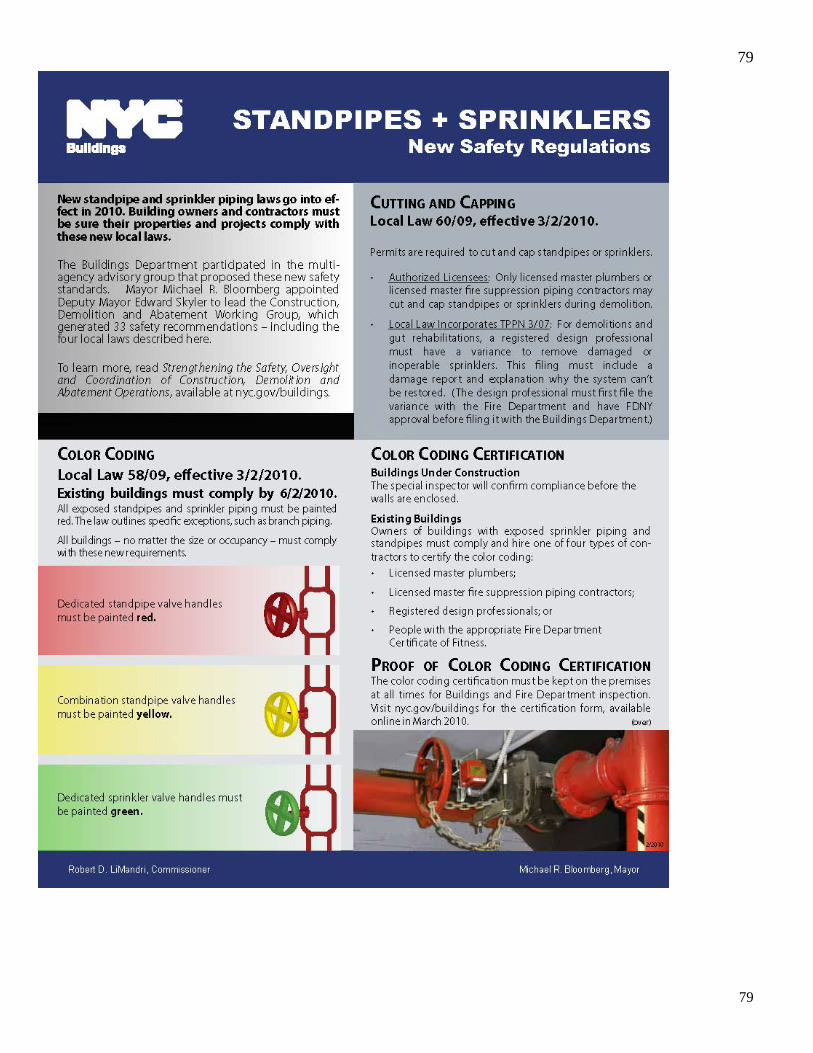
79
79
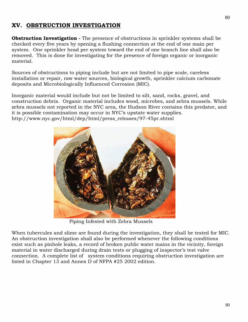
80
80
XV. OBSTRUCTION INVESTIGATION Obstruction Investigation - The presence of obstructions in sprinkler systems shall be checked every five years by opening a flushing connection at the end of one main per system. One sprinkler head per system toward the end of one branch line shall also be removed. This is done for investigating for the presence of foreign organic or inorganic material. Sources of obstructions to piping include but are not limited to pipe scale, careless installation or repair, raw water sources, biological growth, sprinkler calcium carbonate deposits and Microbiologically Influenced Corrosion (MIC). Inorganic material would include but not be limited to silt, sand, rocks, gravel, and construction debris. Organic material includes wood, microbes, and zebra mussels. While zebra mussels not reported in the NYC area, the Hudson River contains this predator, and it is possible contamination may occur in NYC’s upstate water supplies. http://www.nyc.gov/html/dep/html/press_releases/97-45pr.shtml
Piping Infested with Zebra Mussels When tubercules and slime are found during the investigation, they shall be tested for MIC. An obstruction investigation shall also be performed whenever the following conditions exist such as pinhole leaks, a record of broken public water mains in the vicinity, foreign material in water discharged during drain tests or plugging of inspector’s test valve connection. A complete list of system conditions requiring obstruction investigation are listed in Chapter 13 and Annex D of NFPA #25 2002 edition.
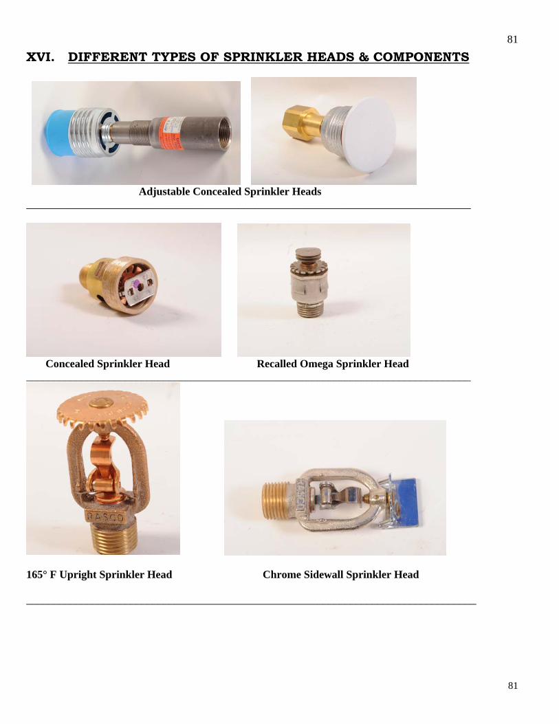
81
81
XVI. DIFFERENT TYPES OF SPRINKLER HEADS & COMPONENTS
Adjustable Concealed Sprinkler Heads _________________________________________________________________________________
Concealed Sprinkler Head Recalled Omega Sprinkler Head _________________________________________________________________________________
165° F Upright Sprinkler Head Chrome Sidewall Sprinkler Head __________________________________________________________________________________

82
82
Adjustable Concealed Sprinkler Head 165°F Upright Sprinkler head __________________________________________________________________________________
Conventional Sprinkler Heads ESFR (286°F) Sprinkler Heads

83
83
Horizontal Sidewall Sprinkler Head Recalled ON-OFF Sprinkler head __________________________________________________________________________________
Sprinkler Head with a factory protective cap Horizontal side wall Sprinkler Head __________________________________________________________________________________
200°F in Rack Sprinkler Head Large Drop 286°F Sprinkler Head _________________________________________________________________________________
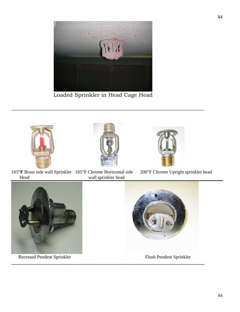
84
84
Loaded Sprinkler in Head Cage Head ______________________________________________________________________
165°F Brass side wall Sprinkler 165°F Chrome Horizontal side 200°F Chrome Upright sprinkler head Head wall sprinkler head
Recessed Pendent Sprinkler Flush Pendent Sprinkler __________________________________________________________________________________
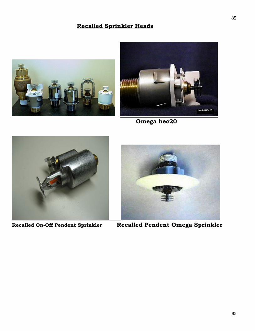
85
85
Recalled Sprinkler Heads
Omega hec20
Recalled On-Off Pendent Sprinkler Recalled Pendent Omega Sprinkler
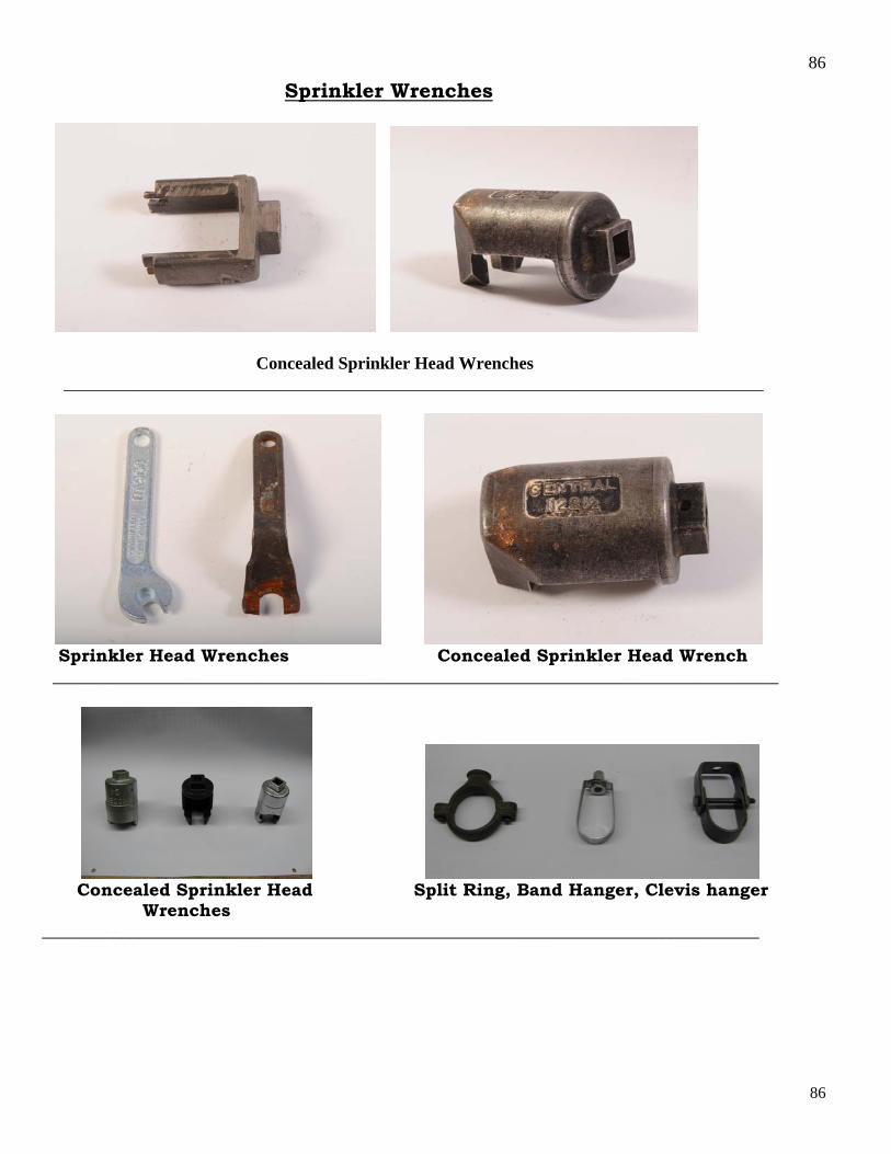
86
86
Sprinkler Wrenches
Concealed Sprinkler Head Wrenches ________________________________________________________________________________
Sprinkler Head Wrenches Concealed Sprinkler Head Wrench ___________________________________________________________________________________
Concealed Sprinkler Head Split Ring, Band Hanger, Clevis hanger Wrenches __________________________________________________________________________________
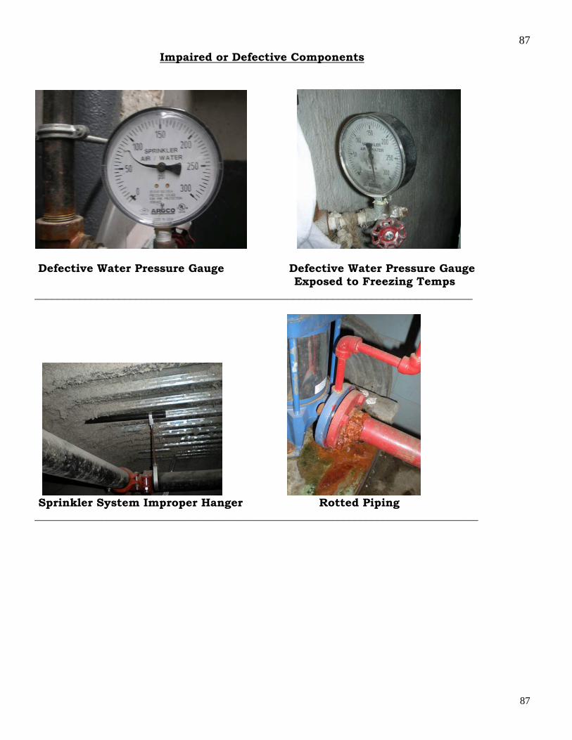
87
87
Impaired or Defective Components
Defective Water Pressure Gauge Defective Water Pressure Gauge Exposed to Freezing Temps ______________________________________________________________________________
Sprinkler System Improper Hanger Rotted Piping _______________________________________________________________________________

88
88
Valves and Valve Connections
OS & Y valve Not Sealed, Locked, Electronically Corroded Curb Valve in Monitored, Labeled and Valve Handle Not Painted Sidewalk Vault ____________________________________________________________________________________
Correct Installation of Hydracually Fire Department Test Manifold Calculated Wet System with Alarm Valve
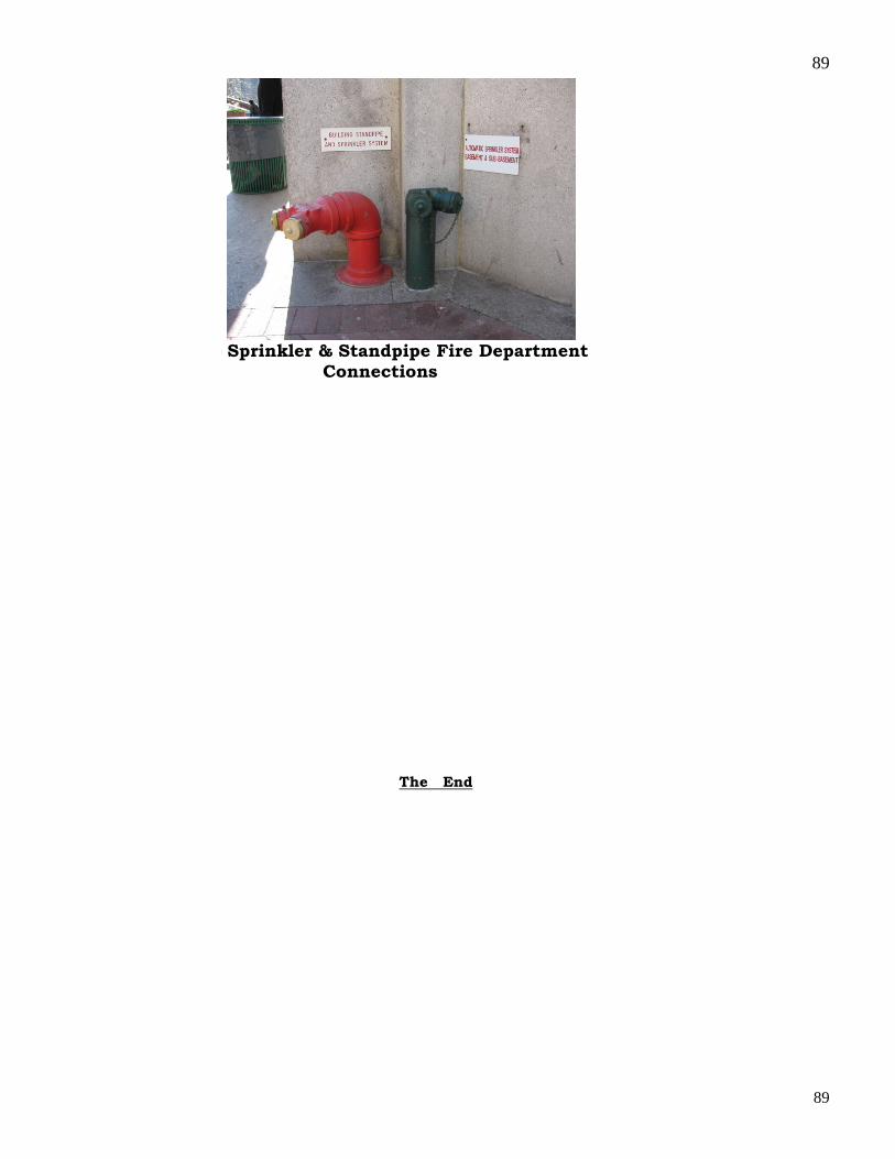
89
89
Sprinkler & Standpipe Fire Department Connections
The End