Embed Size (px)
Citation preview

Advanced Steel Construction Vol. 5, No. 3, pp. 273-288 (2009) 273
FIRE BEHAVIOUR OF STEEL-CONCRETE COMPOSITE MEMBERS WITH AUSTENITIC STAINLESS STEEL
C. Renaud 1 and B. Zhao 2,*
1 Dr, Fire Research and Engineering Section, CTICM,
Espace technologique l’Orme des Merisiers F-91193 Saint Aubin - France 2 Head of the Fire Research section, Research and Engineering Section, CTICM,
Espace technologique l’Orme des Merisiers F-91193 Saint Aubin - France *(Corresponding author: E-mail: [email protected])
Received: 13 November 2007; Revised: 7 March 2008; Accepted: 26 March 2008
ABSTRACT: Within the scope of a European research project, a part of the work was focused on both experimental and numerical investigation of the fire performance of steel-concrete composite members with austenetic stainless steel. For the experimental investigation, an important number of fire tests have been carried out with different composite members. Based on these fire tests, corresponding numerical analysis has been made using advanced calculation models to check, on the one hand, the validity of these models, and on the other hand, to perform parametric studies with the purpose of developing simple calculation methods in order to provide a practical rule for daily design of composite members with austenitic stainless steel. It has been shown through the comparison with both numerical results and fire tests that the proposed calculation methods are suitable to predict with a good accuracy the fire resistance of composite columns with hollow stainless steel section and partially protected floor beams with stainless steel part exposed to fire. Keywords: Fire resistance, stainless steel, composite column with hollow steel section, floor-beams
1. INTRODUCTION Although many European research projects have already shown its remarkable fire resistance, the use of high-strength austenitic stainless steel as steel-concrete composite members remains not very common in practice because of the lack of knowledge on the fire behaviour of this type of structural members. Due to its good performance at elevated temperatures, stainless steel could become a practical alternative solution to conventional structural carbon steel reducing for example the cross-section size of steel profiles or the ratio of additional reinforcing bars which often are needed with carbon steel to achieve the required fire resistance. So, in order to investigate the fire behaviour of composite members with austenitic stainless steel, a total of nine fire tests have been carried out, including both rectangular hollow sections filled with concrete and partially protected slim-floor beams with stainless steel part exposed to fire and carbon steel part encased in concrete. All test members were in grade EN 1.4404 stainless steel, one of the grades commonly used in construction. Based on fire tests, corresponding numerical analyses have been made using the advanced finite element model SISMEF capable of simulating the mechanical behaviour and resistance of composite members exposed to fire. This model was proved already to be in good agreement with several fire tests performed on composite members with conventional structural carbon steel [1-4]. This numerical model was used then to perform parametric studies in order to develop simple design rules for composite columns and floor beams. The proposed design methods are consistent with the general flow charts in EN 1994-1-2 used to check the fire resistance of composites members but including some specific characteristics [5]. The present paper is then devoted to present test results, corresponding numerical simulations and the development of design guidance for investigated composite members with stainless steel.
The Hong Kong Institute of Steel Construction www.hkisc.org
274 Fire Behaviour of Steel-Concrete Composite Members with Austenitic Stainless Steel
2. EXPERIMENTAL PROGRAM Fire tests on seven columns and two beams were conducted in France (Fire station of CTICM in “Maizières-Les-Metz”) for the purpose of obtaining experimental evidence about the structural behaviour of stainless steel-concrete composite members subjected to fire. 2.1 Test Specimens The main characteristics of tested composite columns are summarized in Table 1. All columns were square hollow steel sections with cross-section sizes ranging from 150x8 to 300x8 mm. The column length was 4000 mm. Stainless steel tubes were filled with either reinforced or non-reinforced concrete core. Additional reinforcement, if used, was in four identical longitudinal bars, with a diameter chosen to achieve a ratio of reinforcement As/(As+Ac) of approximately two percent and an axis distance of reinforcing bars us = 30 mm. The stainless steel grade was EN 1.4401. Columns were tested under centric or eccentric load. For centrically loaded columns, a small loading eccentricity of 5 mm was applied to both column ends in order to induce an overall flexural buckling mode of failure under the fire condition.
Table 1. Characteristics of Tested Composite Columns with Hollow Steel Section
Cross-section Rebars Loading Length Column
be (mm)
Stainless Steel grade Diameter
Cover*(mm)
Load (KN)
Ecc. (mm)
n°1 1508 EN1.4401 none - 400 5 mm 4000
n°2 2008 EN1.4401 none - 240 0.25b** 4000
n°3 2008 EN1.4401 4Φ14 30 630 5 mm 4000
n°4 2008 EN1.4401 4Φ14 30 240 0.25b** 4000
n°5 3008 EN1.4401 none - 750 0.5b** 4000
n°6 3008 EN1.4401 4Φ22 30 1000 0.125 b** 4000
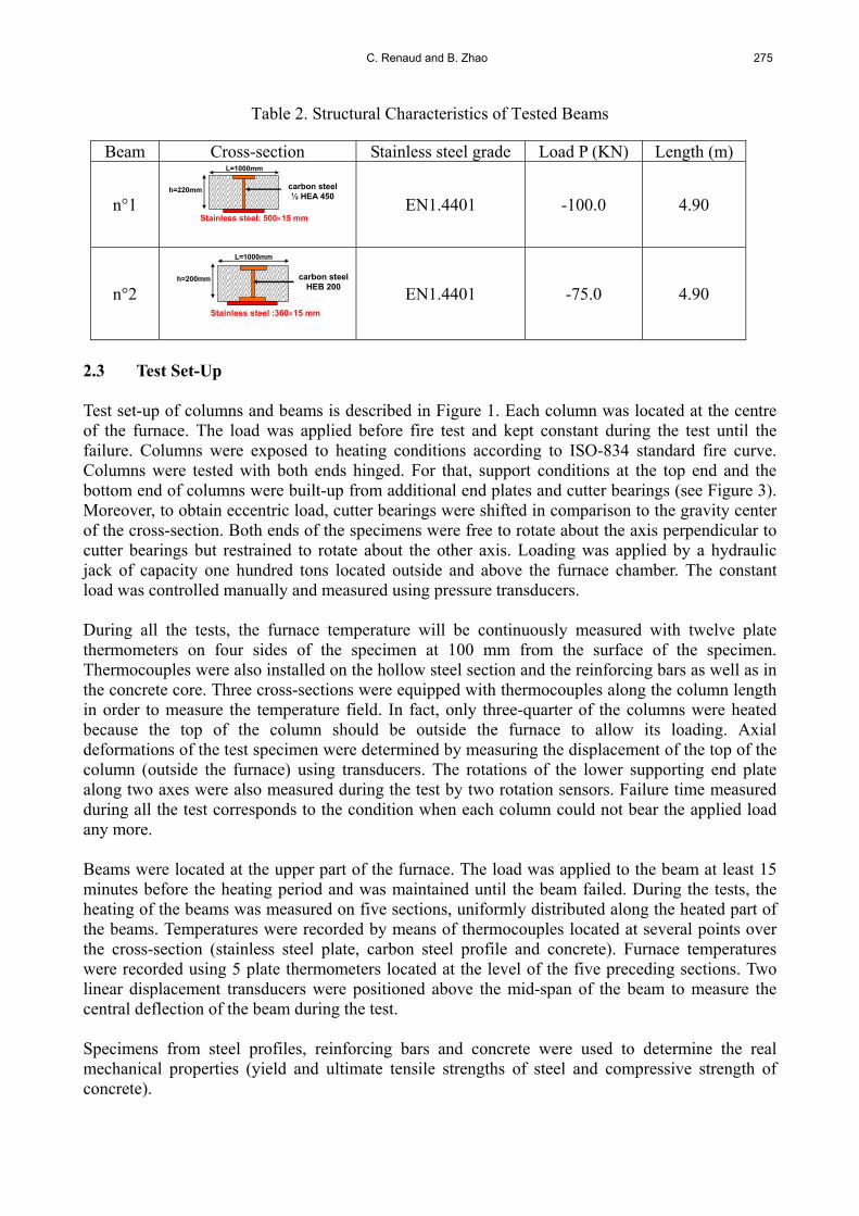
n°7 3008 EN1.4401 4Φ22 30 800 0.25 b** 4000 * distance between the axis of longitudinal reinforcements and the border of concrete core ** external side of hollow steel section The main structural characteristics of tested beams are reported in Table 2. Beams were simply supported hybrid I-section (stainless steel lower flange, carbon steel web and top flange) with a span of 5m. Two different I cross-sections have been tested. The first beam is composed of half HEA 450 and 15mm thick 500 mm stainless steel plate. The second beam is composed of carbon steel HEB 200 and 15mm thick 360 mm stainless steel plate. The carbon steel part of the beams was partially encased with concrete. The loading was applied in two points so that uniform bending moment was present in mid-span area of beams. The load P applied on beams was 100 kN and 75 kN respectively.
C. Renaud and B. Zhao 275
Table 2. Structural Characteristics of Tested Beams
Beam Cross-section Stainless steel grade Load P (KN) Length (m)
n°1
L=1000mm
Stainless steel: 50015 mm
carbon steel ½ HEA 450
h=220mm
EN1.4401 -100.0 4.90
n°2 carbon steel
HEB 200
Stainless steel :36015 mm
L=1000mm
h=200mm
EN1.4401 -75.0 4.90
2.3 Test Set-Up Test set-up of columns and beams is described in Figure 1. Each column was located at the centre of the furnace. The load was applied before fire test and kept constant during the test until the failure. Columns were exposed to heating conditions according to ISO-834 standard fire curve. Columns were tested with both ends hinged. For that, support conditions at the top end and the bottom end of columns were built-up from additional end plates and cutter bearings (see Figure 3). Moreover, to obtain eccentric load, cutter bearings were shifted in comparison to the gravity center of the cross-section. Both ends of the specimens were free to rotate about the axis perpendicular to cutter bearings but restrained to rotate about the other axis. Loading was applied by a hydraulic jack of capacity one hundred tons located outside and above the furnace chamber. The constant load was controlled manually and measured using pressure transducers. During all the tests, the furnace temperature will be continuously measured with twelve plate thermometers on four sides of the specimen at 100 mm from the surface of the specimen. Thermocouples were also installed on the hollow steel section and the reinforcing bars as well as in the concrete core. Three cross-sections were equipped with thermocouples along the column length in order to measure the temperature field. In fact, only three-quarter of the columns were heated because the top of the column should be outside the furnace to allow its loading. Axial deformations of the test specimen were determined by measuring the displacement of the top of the column (outside the furnace) using transducers. The rotations of the lower supporting end plate along two axes were also measured during the test by two rotation sensors. Failure time measured during all the test corresponds to the condition when each column could not bear the applied load any more. Beams were located at the upper part of the furnace. The load was applied to the beam at least 15 minutes before the heating period and was maintained until the beam failed. During the tests, the heating of the beams was measured on five sections, uniformly distributed along the heated part of the beams. Temperatures were recorded by means of thermocouples located at several points over the cross-section (stainless steel plate, carbon steel profile and concrete). Furnace temperatures were recorded using 5 plate thermometers located at the level of the five preceding sections. Two linear displacement transducers were positioned above the mid-span of the beam to measure the central deflection of the beam during the test. Specimens from steel profiles, reinforcing bars and concrete were used to determine the real mechanical properties (yield and ultimate tensile strengths of steel and compressive strength of concrete).

276 Fire Behaviour of Steel-Concrete Composite Members with Austenitic Stainless Steel
Figure 1. Test Set-Up of Structural Members
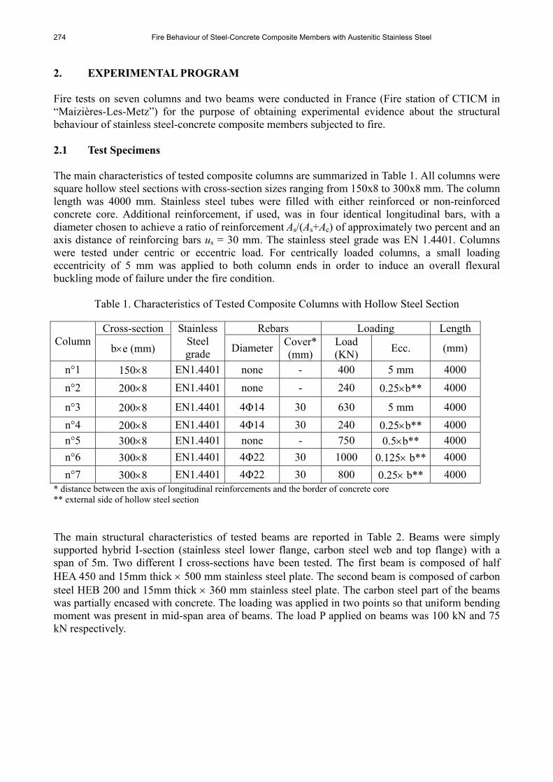
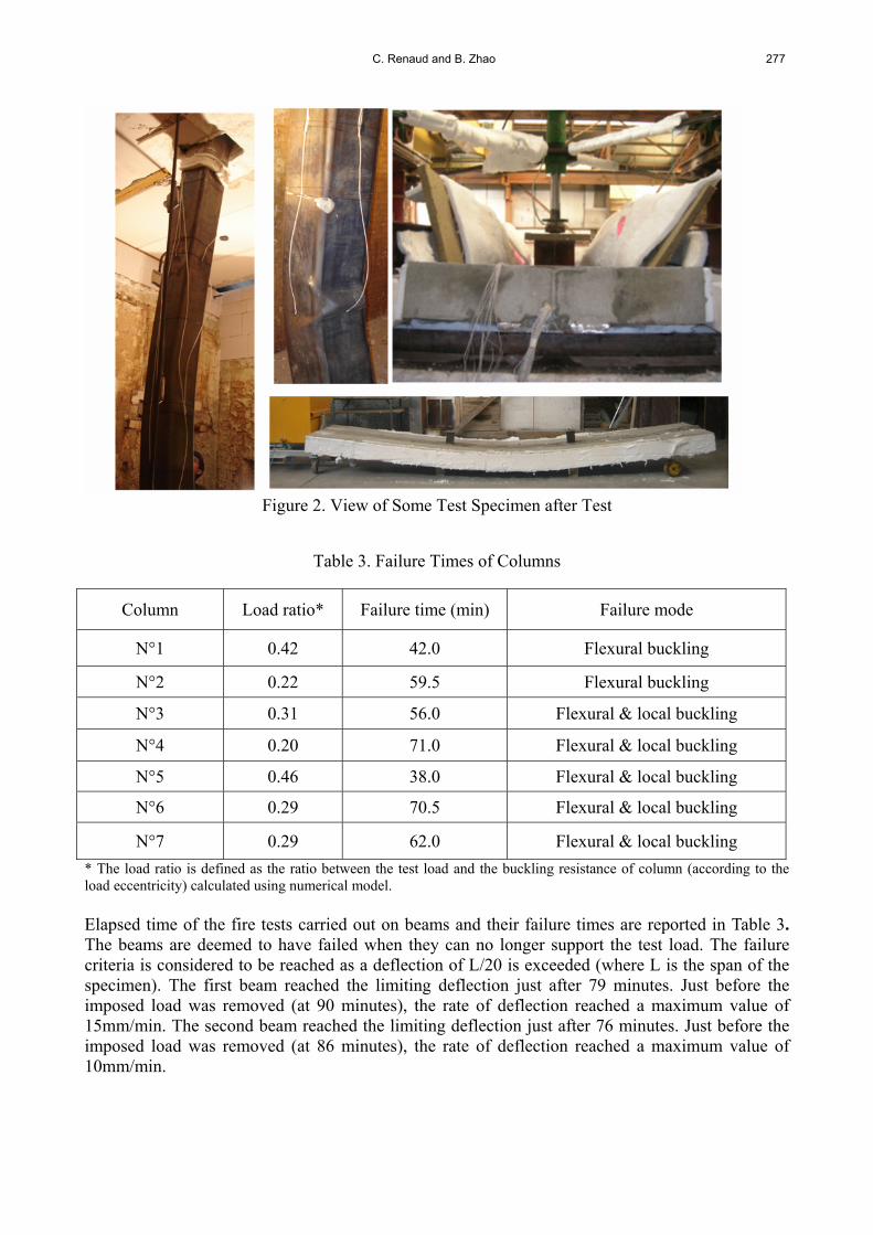
2.4 Test Results Experimental failure times of columns which correspond to the condition when columns could not bear the applied load any more are reported in Table 3. All failure times were higher than expected fire ratings, namely R30 and R60. The main reason is that initial design of columns was made using nominal values of the mechanical properties of materials and assuming a uniform temperature distribution along full column height. Column failures were caused by simple global flexural buckling or flexural buckling combined with local buckling (see Figure 2). The observation after the test shows that the maximum deflection of the column was located either close to the bottom (lower part of the column) or near the mid-height of the specimen. For specimens with the larger cross-section (300x8mm), maximum deflection was observed on the lower part of the columns (due to the non-uniform heating of columns during fire tests). The thermocouple recordings on the other RHS columns showed that columns can be considered to be uniformly heated. In this case, the maximum deflection was observed near the mid-height of the specimen. It is observed also that the local buckling had occurred in hollow steel section of tested columns with large cross-section sizes (200x8mm and 300x8mm). This local buckling may be explained by the fact that these columns have excessive wall slenderness. No local buckling has been observed in the column with small cross-section sizes (150x8mm).
C. Renaud and B. Zhao 277
Figure 2. View of Some Test Specimen after Test
Table 3. Failure Times of Columns
Column Load ratio* Failure time (min) Failure mode
N°1 0.42 42.0 Flexural buckling
N°2 0.22 59.5 Flexural buckling
N°3 0.31 56.0 Flexural & local buckling
N°4 0.20 71.0 Flexural & local buckling
N°5 0.46 38.0 Flexural & local buckling
N°6 0.29 70.5 Flexural & local buckling
N°7 0.29 62.0 Flexural & local buckling
* The load ratio is defined as the ratio between the test load and the buckling resistance of column (according to the load eccentricity) calculated using numerical model. Elapsed time of the fire tests carried out on beams and their failure times are reported in Table 3. The beams are deemed to have failed when they can no longer support the test load. The failure criteria is considered to be reached as a deflection of L/20 is exceeded (where L is the span of the specimen). The first beam reached the limiting deflection just after 79 minutes. Just before the imposed load was removed (at 90 minutes), the rate of deflection reached a maximum value of 15mm/min. The second beam reached the limiting deflection just after 76 minutes. Just before the imposed load was removed (at 86 minutes), the rate of deflection reached a maximum value of 10mm/min.
278 Fire Behaviour of Steel-Concrete Composite Members with Austenitic Stainless Steel
Table 4. Failure Time of Tested Beams
Beams Load ratio* Fire duration (min) Failure time (min) N°1 0.43 90 79 N°2 0.65 86 76
* the load ratio is defined as the ratio between the maximum moment due to applied loads and the moment resistance at room temperature obtained from numerical analysis. 3. NUMERICAL SIMULATIONS The mechanical behaviour of tested composite members has been simulated using the FEM model SISMEF. Temperature distributions in members have been obtained separately, either from 2D heat transfer analyses (based on finite difference or finite element method) or from test data. These temperatures have been used as input data for SISMEF. 3.1 Assumptions for Numerical Simulations In addition to the loading, boundary and heating conditions described in the previous paragraph, the fire behaviour of composite members has been analysed with the following assumptions: The thermal and mechanical material properties of concrete and reinforcing steel bars as a
function of temperature are in accordance with EN 1994-1-2. Material models for stainless steel are from EN 1993-1-2 [6]. It should be underlined that the creep strains of steel and concrete are implicitly included in the stress-strain relationships at elevated temperatures. Moreover, the effect of residual stresses is neglected.
Temperature distributions have been assumed to be uniform over the column height, except at the top of the column where a temperature gradient has been taken into account. The reason is that the top of the column was outside the furnace during the test and was not heated directly by the fire. Temperature distribution over the cross-section of column has been computed separately from 2D heat transfer analysis. To calculate the heat flow transmitted to the surface of hollow steel section during the fire exposure, it is necessary to introduce into the model the values of the convection heat transfer coefficient (hc), the emissivity of fire (εf ) and the emissivity of steel (m). In practice, whatever the nature of materials, the convection coefficient inside the furnaces is taken equal to hc=25 W/m²K under ISO fire. In EN 1991-1-2 [7] and EN 1993-1-2, the emissivity of the fire is taken in general as unity. In the present work, the emissivity of the fire is also assumed as unity. The surface emissivity of the column is applied in accordance with EN 1993-1-2, namely m =0.4. The influence of moisture is considered in a simplified way in the calculation of the temperature filed of columns by assuming that all moisture evaporates, without any moisture mass transfer, at the temperature of 100°C or another temperature within a narrow range with the heat of evaporation giving a corresponding change in the enthalpy-temperature curve. Direct heat transfer was assumed between stainless steel hollow section and concrete core (no gap due to differential thermal elongation of materials).
For beams, temperature distribution has been assumed uniform along their length. The temperature development of the two beam tests was modelled numerically with the computer code ANSYS [8], using the same parameters as those adopted for columns and an emissivity of 0.7 for concrete slab.
C. Renaud and B. Zhao 279
The mechanical interaction between the hollow steel section and the concrete core is neglected, that is slipping has been assumed to occur without significant bond between the steel wall and the concrete core.
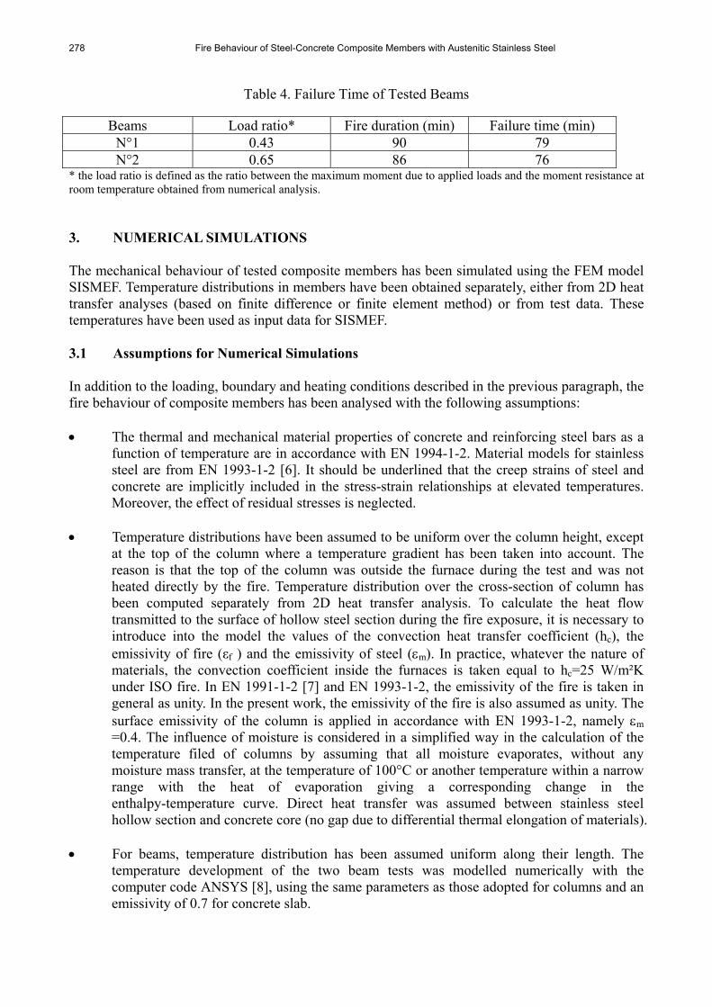
Contribution of the concrete slab on the mechanical fire resistance of beams is neglected. 3.2 Presentation of Some Results The measured temperature rises on composite members were systemically compared to the predicted temperature rises. As example, Figure 3 shows comparisons for reinforced column n°3 and beam n°1.
0
100
200
300
400
500
600
700
800
900
1000
0 5 10 15 20 25 30 35 40 45 50 55 60 65
Calculation
Test
Time (min)
Temperature (°C)
1
4
3
2
T1T4
T
T2
0
100
200
300
400
500
600
700
800
900
1000
0 20 40 60 80 100
Calculation
Test
Time (min)
Temperature (蚓 )
B/4 B/4
h/2
h/4
1 2
3
4
5 6
1, 2
3
4
56
a) Composite column n°3 b) Floor-beam n°1
Figure 3. Comparison between Calculated and Predicted Temperatures
The temperature rises predicted for the hollow steel sections are in good agreement with the measured ones. However, Figure 3 shows fairly large discrepancies between the predicted temperatures and the measured temperatures, particularly for the first 20 minutes. In fact, predicted temperatures rise more slowly. The difference is less than 150°C during the early stage of the tests and decreases quickly with the fire duration. The faster rise in temperature of the hollow steel section might be explained by the role of “heat shield” played by the gap which occurs usually between the hollow section and the concrete core of heated composite columns. This gap is due to the differential thermal elongation of materials (steel and concrete) in the radial direction. It interrupts direct heat conduction between the steel wall and the concrete core. The concrete core is mainly heated then by the thermal radiation from the heated hollow steel section. The temperatures in the longitudinal reinforcing steel bars are evaluated satisfactorily between 0 to 100°C. Once the temperature of 100°C is reached close to the reinforcement, calculated temperatures become more important than those measured (the maximum difference is about 200°C). Globally, the predicted temperature rise rate beyond 100°C is analogous with that observed in test, but somewhat translated towards lower time instants. This translation between the curves is due, on the one hand, to the delaying effect as a result of the gap between the hollow steel section and the concrete core (not taken into account in the thermal analyses) and on the other hand, to the time necessary to the vaporisation of water really enclosed in the concrete. With regard to the point inside the concrete core, the agreement is not so good, but can nevertheless be considered as satisfactory. The difference with calculated curves is of no significant consequence: for low temperatures, the concrete mechanical properties are not affected and for higher temperatures the calculated curve is on the safe side.

280 Fire Behaviour of Steel-Concrete Composite Members with Austenitic Stainless Steel
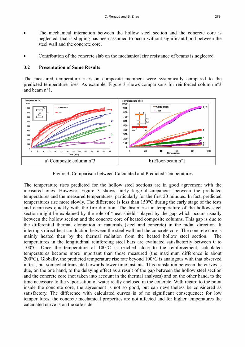
As seen during tests, the bottom of the floor-beam heated up faster than the top, due to fire protection given by the concrete slab. Moreover, it can be noted that the temperatures of stainless steel plates obtained from the numerical model are higher than the test data between 10 to 70 minutes. Then, they become quite close to the measured temperatures. The largest temperature difference in this case is about 100°C at 45 minutes. One reason for this difference might be that the surface properties of the stainless steel plate undergo some changes, which could affect the value of emissivity during the fire exposure. Globally, temperatures calculated for the carbon steel profile are quite close to the measured values. Finally, assuming the thermal parameters recommended in EN 1993-1-2 for stainless steel, the temperature rises predicted for the hollow steel sections are in good agreement with the measured ones. Globally, all calculated temperatures remain overall on the side safe. The many temperature rises recorded during the test allow introducing temperature fields with enough accuracy in the mechanical simulations. So, calculated as well as experimental temperature fields have been systematically used to check the mechanical analyses conducted with SISMEF. As example, axial displacement calculated at the top of the reinforced column n°7 is shown in Figure 4. These displacements are compared with the test values. Same comparison is also given in for beam n°1. From this figure, it can be noted that there is a reasonably good agreement between measured and calculated displacements. The numerical model SISMEF predicts the deformation behaviour of the tested composite columns at a satisfactory level of accuracy. During the early stages of the fire exposure, axial displacement of column increases rapidly due to the quick heating of the external unprotected hollow steel section. As the steel column expands more rapidly than the concrete core, it carries all the applied load. With temperature increase high enough, the load becomes critical due to the decrease of steel strength at elevated temperatures. Then the steel (as well as the column) suddenly contracts with eventual local buckling. At this time the concrete core is loaded almost suddenly and then supports progressively more and more the load with temperature rises. The concrete core, due to lower thermal conductivity and higher heat capacity of concrete, loses its strength more slowly than steel. It provides the fire resistance of the column at these later stages of fire exposure. If the concrete core is reinforced, the composite column can remain stable and the axial displacement decrease more slowly. The strength of the concrete also decreases with time and ultimately, when the concrete core can no longer support the load, failure occurs by buckling. It can be seen that there is also a good correlation between the predicted and the measured displacements of beam, with some differences at the end of test. Displacement increases approximately linearly during the first stage of test and increase very rapidly just before failure occurs by flexural.
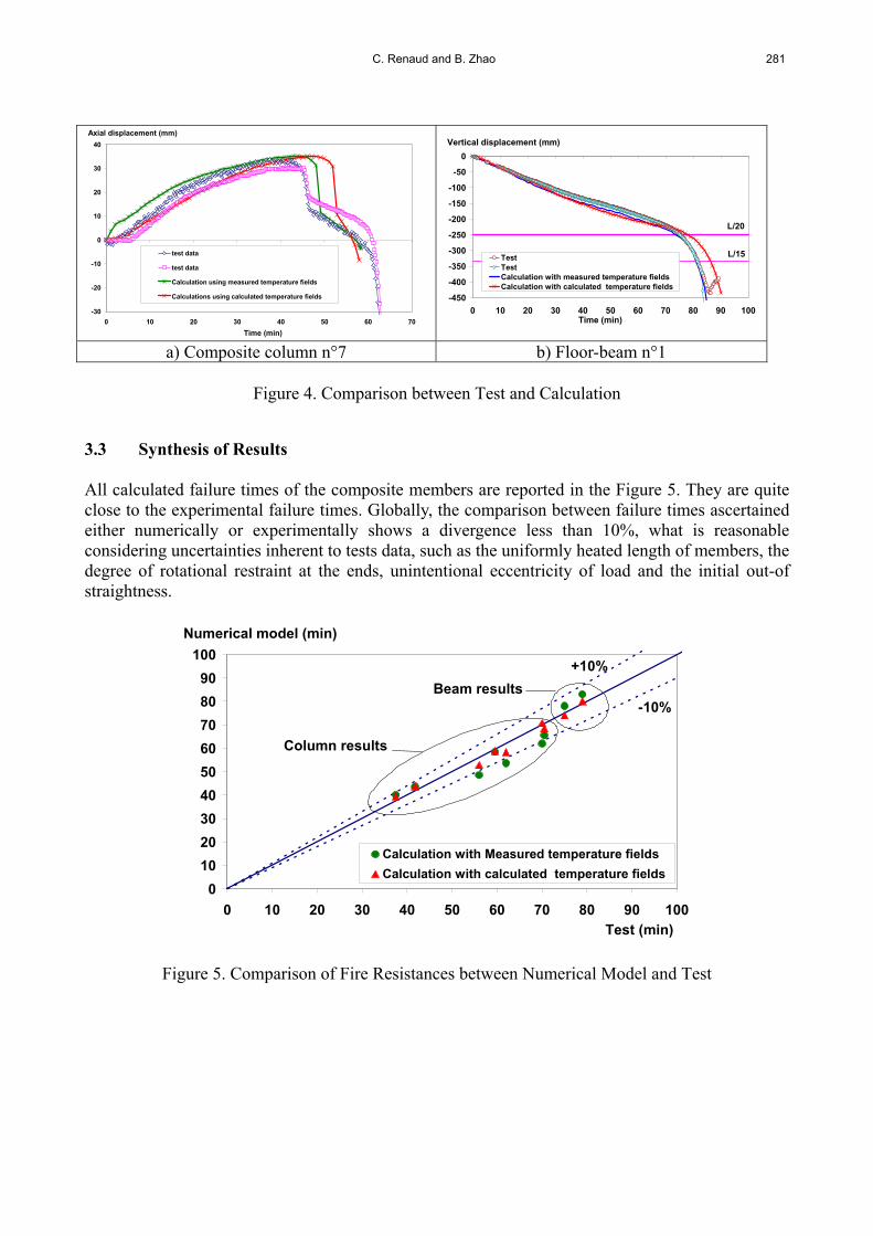
C. Renaud and B. Zhao 281
-30
-20
-10
0
10
20
30
40
0 10 20 30 40 50 60 70
test data
test data
Calculation using measured temperature fields
Calculations using calculated temperature fields
Axial displacement (mm)
Time (min)
-450
-400
-350
-300
-250
-200
-150
-100
-50
0
0 10 20 30 40 50 60 70 80 90 100
TestTestCalculation with measured temperature fieldsCalculation with calculated temperature fields
Time (min)
Vertical displacement (mm)
L/20
L/15
a) Composite column n°7 b) Floor-beam n°1
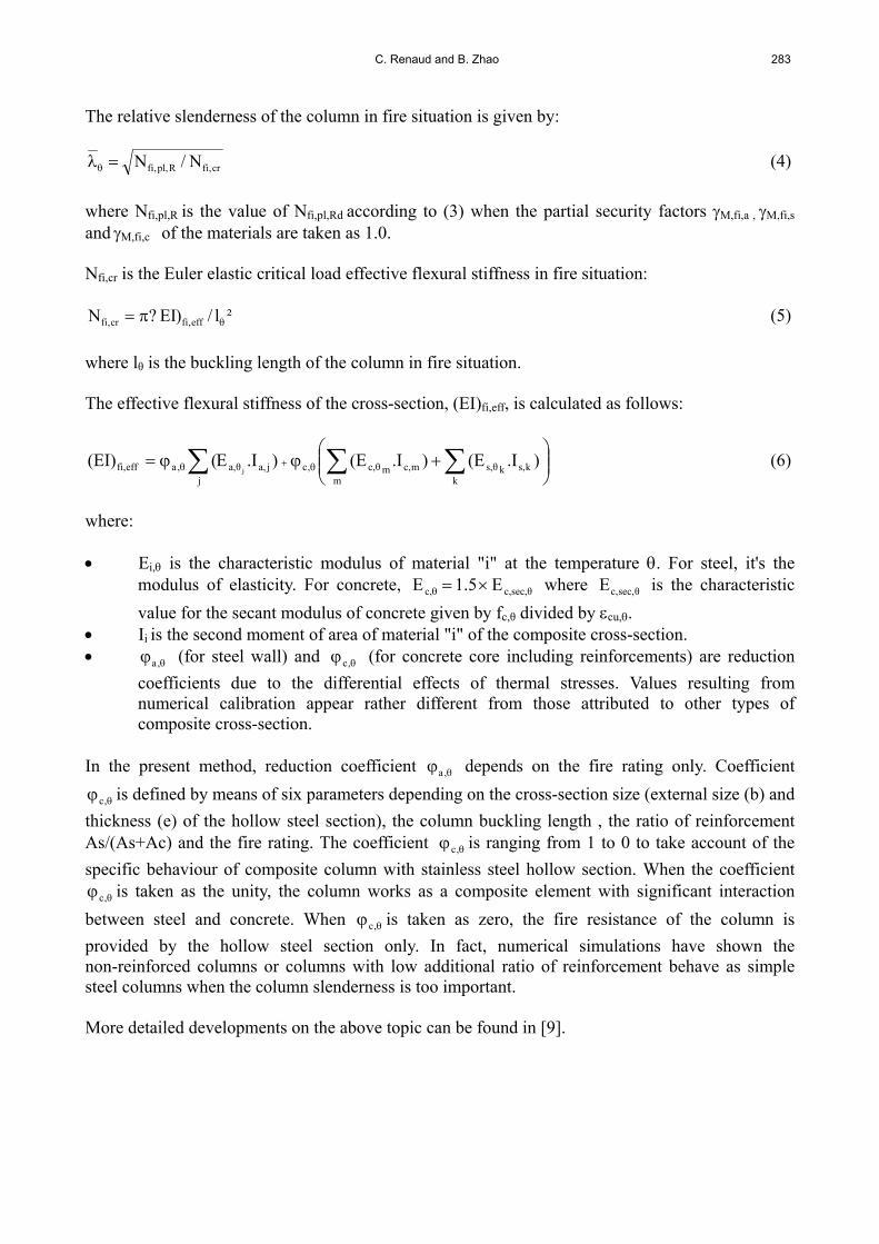
Figure 4. Comparison between Test and Calculation 3.3 Synthesis of Results All calculated failure times of the composite members are reported in the Figure 5. They are quite close to the experimental failure times. Globally, the comparison between failure times ascertained either numerically or experimentally shows a divergence less than 10%, what is reasonable considering uncertainties inherent to tests data, such as the uniformly heated length of members, the degree of rotational restraint at the ends, unintentional eccentricity of load and the initial out-of straightness.
0
10
20
30
40
50
60
70
80
90
100
0 10 20 30 40 50 60 70 80 90 100
Calculation with Measured temperature fields
Calculation with calculated temperature fields
Test (min)
Numerical model (min)
+10%
-10%Beam results
Column results
Figure 5. Comparison of Fire Resistances between Numerical Model and Test

282 Fire Behaviour of Steel-Concrete Composite Members with Austenitic Stainless Steel
4. DEVELOPEMENT OF DESIGN GUIDANCE Parametric studies with the purpose of developing simple calculation models providing a practical rule for daily design have been performed with FEM model SISMEF by varying sensitive parameters susceptible of affecting the fire resistance of composite members under standard fire conditions, such as cross section size, load conditions, eccentricity of loading, buckling length, etc. 4.1 Main Features of Proposed Simple Calculation Method for Composite Columns The simplified design method follows the general flow chart specified in 4.3.5.1.1 of EN 1994-1-2 to check other types of composite columns but includes some specific characteristics which are presented hereafter. 4.1.1 Determination of the axial buckling load in fire situation For a given temperature distribution within the cross-section, the load bearing capacity of a composite column, Nfi,Rd, can be determined from an appropriate buckling column curve which relates the load capacity, Nfi,Rd, to the plastic load, Nfi,pl,Rd, and the elastic critical load, Nfi,cr, as follows:
Rdpl,fi,Rdfi, N)(N (1)
where is the reduction factor for flexural buckling depending on the relative slenderness θ. The reduction factor for flexural buckling is expressed by the following relationships (familiar in steel construction):
22
1
(2)
with 20 )(1
2
1 and =0.76 and 2.00 (buckling curve "d")
The design value of the plastic resistance to axial compression in the fire situation is given by:
k mcfi,M,θc,.sfi,M,θsy,ks,θc,
jafi,M,θay,ja,Rdpl,fi, )/γf(A)/γf(A)/γ.f(AN
mmc,kj (3)
where: Ai is the area of the element "i" of the cross-section. fay,θ, fsy,θ and fc,θ are the characteristic strengths at elevated temperature of the steel of
hollow section, the steel of reinforcing bars and the concrete respectively. For hollow section, the 0.2 % proof characteristic strength of stainless steel is used.
,c is a reduction coefficient taking into account the differential effects of thermal stresses.
It's the same coefficient as that used for the calculation of the effective flexural stiffness.
C. Renaud and B. Zhao 283
The relative slenderness of the column in fire situation is given by:
cr,fiR,pl,fi N/N (4)
where Nfi,pl,R is the value of Nfi,pl,Rd according to (3) when the partial security factors M,fi,a , M,fi,s
and M,fi,c of the materials are taken as 1.0. Nfi,cr is the Euler elastic critical load effective flexural stiffness in fire situation:
²l/)EI?N eff,ficr,fi (5)
where lθ is the buckling length of the column in fire situation. The effective flexural stiffness of the cross-section, (EI)fi,eff, is calculated as follows:
kks,kθs,
mmc,mθc,,cja,θa,
j,aefffi, ).I(E).I(E).IE((EI)
j (6)
where: Ei, is the characteristic modulus of material "i" at the temperature . For steel, it's the
modulus of elasticity. For concrete, θsec,c,c, E5.1E where θsec,c,E is the characteristic
value for the secant modulus of concrete given by fc,θ divided by cu,. Ii is the second moment of area of material "i" of the composite cross-section. ,a (for steel wall) and ,c (for concrete core including reinforcements) are reduction
coefficients due to the differential effects of thermal stresses. Values resulting from numerical calibration appear rather different from those attributed to other types of composite cross-section.
In the present method, reduction coefficient ,a depends on the fire rating only. Coefficient
,c is defined by means of six parameters depending on the cross-section size (external size (b) and
thickness (e) of the hollow steel section), the column buckling length , the ratio of reinforcement As/(As+Ac) and the fire rating. The coefficient ,c is ranging from 1 to 0 to take account of the
specific behaviour of composite column with stainless steel hollow section. When the coefficient
,c is taken as the unity, the column works as a composite element with significant interaction
between steel and concrete. When ,c is taken as zero, the fire resistance of the column is
provided by the hollow steel section only. In fact, numerical simulations have shown the non-reinforced columns or columns with low additional ratio of reinforcement behave as simple steel columns when the column slenderness is too important. More detailed developments on the above topic can be found in [9].
284 Fire Behaviour of Steel-Concrete Composite Members with Austenitic Stainless Steel
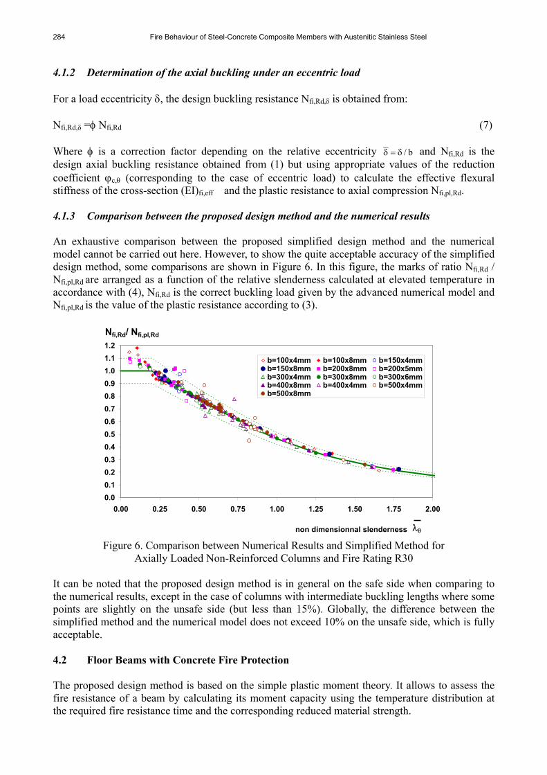
4.1.2 Determination of the axial buckling under an eccentric load For a load eccentricity , the design buckling resistance Nfi,Rd, is obtained from: Nfi,Rd,δ = Nfi,Rd (7) Where is a correction factor depending on the relative eccentricity b/ and Nfi,Rd is the design axial buckling resistance obtained from (1) but using appropriate values of the reduction coefficient c, (corresponding to the case of eccentric load) to calculate the effective flexural stiffness of the cross-section (EI)fi,eff and the plastic resistance to axial compression Nfi,pl,Rd. 4.1.3 Comparison between the proposed design method and the numerical results An exhaustive comparison between the proposed simplified design method and the numerical model cannot be carried out here. However, to show the quite acceptable accuracy of the simplified design method, some comparisons are shown in Figure 6. In this figure, the marks of ratio Nfi,Rd / Nfi,pl,Rd are arranged as a function of the relative slenderness calculated at elevated temperature in accordance with (4), Nfi,Rd is the correct buckling load given by the advanced numerical model and Nfi,pl,Rd is the value of the plastic resistance according to (3).
0.0
0.1
0.2
0.3
0.4
0.5
0.6
0.7
0.8
0.9
1.0
1.1
1.2
0.00 0.25 0.50 0.75 1.00 1.25 1.50 1.75 2.00
b=100x4mm b=100x8mm b=150x4mmb=150x8mm b=200x8mm b=200x5mmb=300x4mm b=300x8mm b=300x6mmb=400x8mm b=400x4mm b=500x4mmb=500x8mm
non dimensionnal slenderness
Nfi,Rd/ Nfi,pl,Rd
Figure 6. Comparison between Numerical Results and Simplified Method for Axially Loaded Non-Reinforced Columns and Fire Rating R30
It can be noted that the proposed design method is in general on the safe side when comparing to the numerical results, except in the case of columns with intermediate buckling lengths where some points are slightly on the unsafe side (but less than 15%). Globally, the difference between the simplified method and the numerical model does not exceed 10% on the unsafe side, which is fully acceptable. 4.2 Floor Beams with Concrete Fire Protection The proposed design method is based on the simple plastic moment theory. It allows to assess the fire resistance of a beam by calculating its moment capacity using the temperature distribution at the required fire resistance time and the corresponding reduced material strength.

C. Renaud and B. Zhao 285
The following simplifying assumptions have been made: The concrete does not contribute to the load bearing capacity at elevated temperatures and
thus may be ignored. Failure of beams occurs when maximum mechanical strain exceeds 2% on the exposed
stainless steel plate. 4.2.1 Main features of proposed simple calculation method The design moment resistance Rdt,fi,M of floor-beams can be determined from:
n
1ifi,Mi,,yiiRdt,fi, /fzAM (8)
where iz is the distance from the plastic neutral axis to the centroid of the elemental area iA . For the calculation of the design value of the moment resistance, the cross-section of the beam is divided into various components: the stainless steel plate, the lower flange of the carbon steel profile (when used); the web of the steel profile (divided in two parts) and the upper flange of the carbon steel profile. For each of these parts, simple rules have been developed which define temperatures and corresponding reduced characteristic strength in function of the standard fire resistance R30, R60, R90 or R120 (see Figure 7 and Table 5).
ef
floor beam Temperature distribution through depth of the beam
Average temperature p 400 lw lf
Depth into the section
stress distribution
NA -
-
Depth into the section
+
bf
hw hl
bp
ep
ew
Figure 7. Temperature and Stress Distributions Along the Depth of Floor Beam
The height hl of the lower part of the web is calculated to:
20
380ln
2
lwl
th
(9)
286 Fire Behaviour of Steel-Concrete Composite Members with Austenitic Stainless Steel
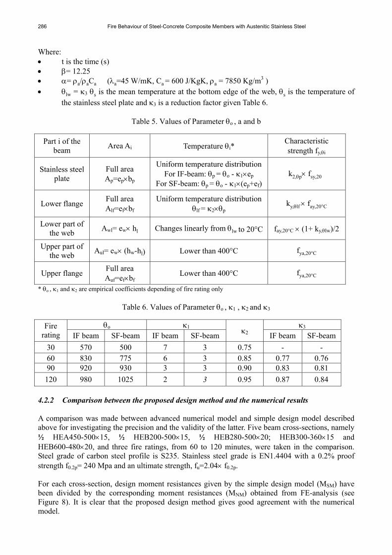
Where: t is the time (s) = 12.25 = a/aCa (a=45 W/mK, Ca = 600 J/KgK, a = 7850 Kg/m3 ) lw = 3 s is the mean temperature at the bottom edge of the web, s is the temperature of
the stainless steel plate and 3 is a reduction factor given Table 6.
Table 5. Values of Parameter o , a and b
Part i of the beam
Area Ai Temperature i* Characteristic strength fy,i
Stainless steel plate
Full area Ap=epbp
Uniform temperature distribution
For IF-beam: p = o - 1ep
For SF-beam: p = o - 1(ep+ef)k2,p fsy,20°
Lower flange Full area Alf=efbf
Uniform temperature distribution lf = 2p
ky,lf fay,20°C
Lower part of the web
Awl= ew hl Changes linearly from lw to 20°C fay,20°C (1+ ky,lw)/2
Upper part of the web
Aul= ew (hw-hl) Lower than 400°C fya,20°C
Upper flange Full area Auf=efbf
Lower than 400°C fya,20°C
* o , 1 and 2 are empirical coefficients depending of fire rating only
Table 6. Values of Parameter o , 1 , 2 and 3
o 1 3 Fire rating IF beam SF-beam IF beam SF-beam
2 IF beam SF-beam
30 570 500 7 3 0.75 - - 60 830 775 6 3 0.85 0.77 0.76 90 920 930 3 3 0.90 0.83 0.81
120 980 1025 2 3 0.95 0.87 0.84
4.2.2 Comparison between the proposed design method and the numerical results A comparison was made between advanced numerical model and simple design model described above for investigating the precision and the validity of the latter. Five beam cross-sections, namely ½ HEA450-50015, ½ HEB200-50015, ½ HEB280-50020; HEB300-36015 and HEB600-48020, and three fire ratings, from 60 to 120 minutes, were taken in the comparison. Steel grade of carbon steel profile is S235. Stainless steel grade is EN1.4404 with a 0.2% proof strength f0.2p= 240 Mpa and an ultimate strength, fu=2.04 f0.2p. For each cross-section, design moment resistances given by the simple design model (MSM) have been divided by the corresponding moment resistances (MNM) obtained from FE-analysis (see Figure 8). It is clear that the proposed design method gives good agreement with the numerical model.

C. Renaud and B. Zhao 287
0.00
0.20
0.40
0.60
0.80
1.00
1.20
60 90 120
IF-BEAM
SF-BEAM
Fire rating (min)
MSM / MNM
+10%
-10%
Figure 8. Comparison of the Proposed Design Method with Numerical Model
4. CONCLUSION In order to investigate the fire behaviour of steel and concrete composite members with austenitic stainless steel, a series of fire tests are conducted within the scope of a European project. The corresponding experimental results are presented in detail in this paper. In parallel, using the advanced finite element model SISMEF, the fire performances of several composite members with stainless austenitic steel have been evaluated and compared with fire test results. These comparisons have shown that the model is capable of predicting the behaviour of composite columns and partially protected Slim-floor beams (failure time, displacements,) with a good accuracy. Then, the fire behaviour of previous composite members has been investigated with a wide range of parametric simulations. Referring to this base of numerical results, simple design methods consistent with the general flow chart used in EN 1994-1-2 to check the other types of composites members but including some specific characteristics have been proposed. It has been shown through the comparison with numerical results that the simple design methods are capable of predicting with a quite good accuracy the fire resistance of composite columns with hollow stainless steel section and partially protected slim-floor beams. REFERENCES [1] Renaud, C., "Modélisation Numérique, Expérimentation et Dimensionnement Pratique des
Poteaux Mixtes Avec Profil Creux Exposés à l’incendie", Thèse de Docteur en génie Civil, INSA de Rennes, France, 2003.
[2] Renaud, C., Aribert, J.M. and Zhao, B., "Advanced Numerical Model for the Fire Resistance of Composite Columns with Hollow Steel Section", Journal of Steel and Composite Structures, 2003, Vol. 3, No. 2, pp. 75-95.

288 Fire Behaviour of Steel-Concrete Composite Members with Austenitic Stainless Steel
[3] Zhao, B. and Aribert, J.M., "Finite Element Method for Steel-Concrete Composite Frames Taking Account of Slip and Large Displacements", European Journal of Finite Element, 1996, Vol. 5, No. 2, pp. 221-249.
[4] Zhao, B., "Modélisation Numérique des Poutres et Portiques Mixtes Acier-béton Avec Glissements et Grands Déplacements", Thèse de docteur en Génie Civil, INSA de RENNES, Franc, 1994.
[5] prEN 1994-1-2, Eurocode 4, “Design of Composite Steel and Concrete Structures: Structural Fire Design”, CEN, 2004.
[6] EN 1993-1-2, Eurocode 3: “Design of Steel Structures – Part 1.2: General Rules – Structural Fire Design”, CEN, 2005.
[7] EN 1991-1-2 - Eurocode 1 "Actions on Structures" – Part 1-2: General Actions – Action on Structures Exposed to Fire, CEN, 2005.
[8] ANSYS, "ANSYS User’s Manual for Revision 8.0 – Volume IV – Theory", Swanson Analysis SYSTEM, INC., Houston USA, 1992.
[9] CTICM, Stainless Steel in Fire (SSIF), Research Contract: RFS-CR-04048; WP2: Composite Members in Fire, Final Report SRI – 07/110 - CR/PB, August 2007.