Embed Size (px)
Citation preview
MASTER’SOFSCIENCEFIREPROTECTIONENGINEERINGCULMINATINGPROJECT
FireAnalysisofTheWalterF.DexterBuildingBuilding34oftheCalifornia Polytechnic,San
LuisObispoCampus
Jeff Jenkins
3/23/2014
1
Statement of Disclaimer This project report is a result of a class assignment; it has been graded and accepted as fulfillment of the course requirements. Acceptance of this report in fulfillment of the course requirements does not imply technical accuracy or reliability. Any use of information in this report is done at the risk of the user. These risks may include, but may not be limited to, catastrophic failure of the device or infringement of patent or copyright laws. California Polytechnic State University at San Luis Obispo and its staff cannot be held liable for any use or misuse of the project.
Keywords: Dexter, Fire, Analysis, Performance, Perscriptive [email protected]
2
TableofContentsExecutive Summary ...................................................................................................... 4
Introduction ................................................................................................................... 5
Egress ............................................................................................................................. 6
Occupancy Classification ............................................................................................ 6
Occupancy Load, Exit Capacity and Exit Arrangement ............................................. 6
Fire Resistance Ratings, Exit Signs and Interior Finish ........................................... 12
Occupant Characteristics .......................................................................................... 15
Pre-Movement and Movement Times ...................................................................... 16
Hand Calculation of Egress Time ............................................................................. 17
Pathfinder .................................................................................................................. 20
Uses and Limitations ................................................................................................. 20
Tenability Performance Criteria................................................................................ 21
Notification .................................................................................................................. 24
Fire Alarm System .................................................................................................... 24
Detection Devices ..................................................................................................... 24
Detection Device Placement ..................................................................................... 28
Scenario ..................................................................................................................... 29
Disposition, Supervisory and Trouble Signals .......................................................... 31
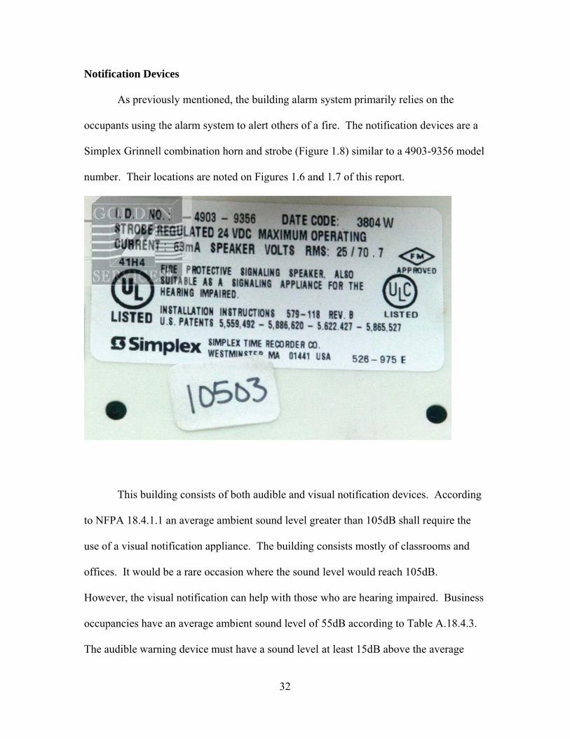
Notification Devices ................................................................................................. 32
Power Supply ............................................................................................................ 34
Maintenance and Testing .......................................................................................... 36
Construction ................................................................................................................ 38
Classification ............................................................................................................. 38
Construction Materials .............................................................................................. 38
Fire Resistance Ratings ............................................................................................. 41
Performance Based Tenability Analysis ................................................................... 43
3
Introduction ............................................................................................................... 43
Fire Scenario ............................................................................................................. 43
Design Fire ................................................................................................................ 44
Temperature .............................................................................................................. 46
Carbon Monoxide ..................................................................................................... 47
Visibility ................................................................................................................... 49
Conclusion ................................................................................................................... 51
4
Executive Summary
The purpose of this report is to provide a fire analysis of the Walter F. Dexter
Building on the California Polytechnic State University, San Luis Obispo Campus. The
report will detail egress analysis, notification systems, and building construction in a
prescriptive approach. The report will also include a performance based analysis of the
building with a designed fire scenario. This performance based analysis will show that in
one of the most likely fire scenarios for the building, there is still ample time for the
occupants to escape safely.
5
Introduction The purpose of this report is to give an initial prescriptive and performance
egress, notification and structural analysis relative to fire protection of the Walter F.
Dexter Building (Building 34) located on the California Polytechnic State University, San
Luis Obispo Campus. The building is a mixed occupancy and includes assembly,
business, industrial, mercantile and storage occupancies as specified in NFPA 101
Chapter 6.1. This report will include floor plans of the building which will specify the
occupancy type for each room as well as the occupant load factor per room. This report
will also specify egress capacities and compare occupant load factors to the egress
capacities in order to ensure there is sufficient egress capacity. Exit corridors, exit sign
placement and the number of exits will also be discussed. All exits in this building were
measured and all capacities were determined using prescribed formulas taken from NFPA
101 unless otherwise noted. For the notification system NFPA 72 was referenced. The
2009 International Building Code (IBC) was used for structural fire protection analysis.
For the performance based egress analysis, occupant characteristics, and pre
movement times will be discussed. Building characteristics such as stairway and
doorway widths taken from the prescriptive analysis are input into a proper hand
calculation in order to give an approximate egress time. Finally, tenability performance
criteria of the building will be discussed. A comparison of computer modeling
(Pathfinder) results for egress and tenability criteria will be made to determine if the
criteria for tenability will be met for a prescribed fire scenario.
6
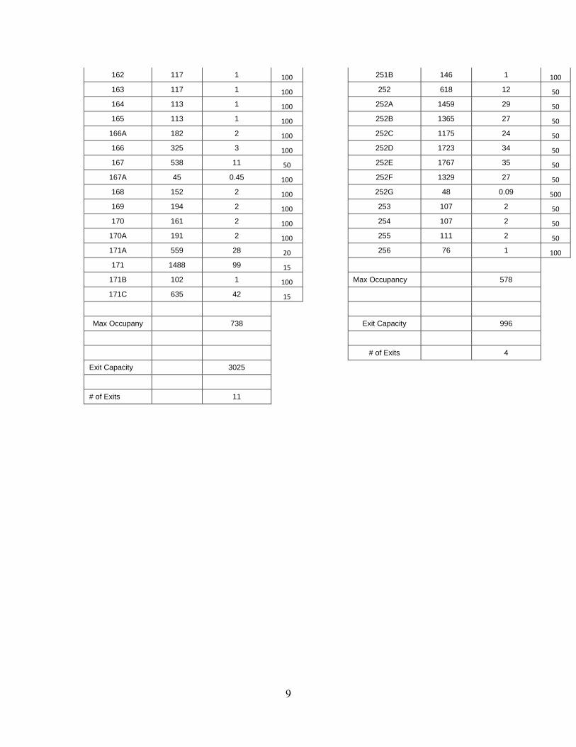
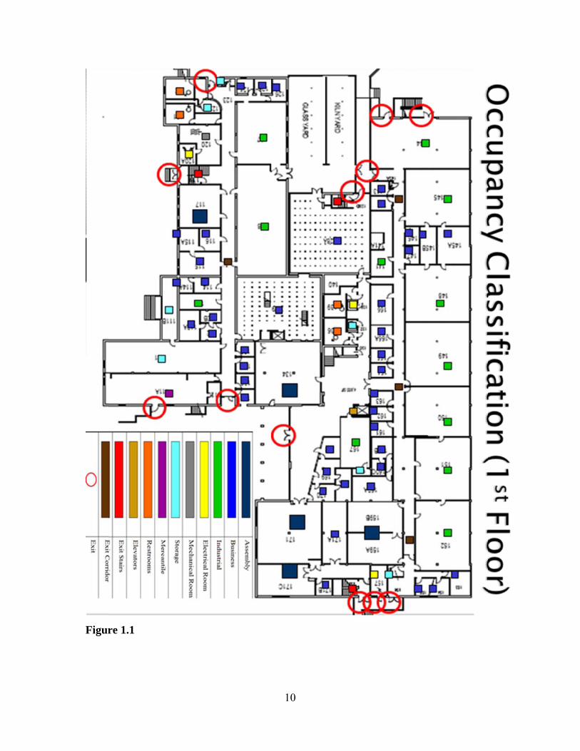
Egress Occupancy Classification
The Walter F. Dexter Building is a mixed occupancy building. The occupancies
include art galleries, labs, classrooms, offices, storage rooms and a vending area. In
order to classify these occupancies NFPA 101 – The Life Safety Code Chapter 6.1 was
consulted. Occupancies were then determined to be Assembly, Industrial, Business,
Storage and Mercantile respectively. Please see Figures 1.1-1.2 for floor plan and
occupancy classification. Points of egress were located as well as exit stairs, exit
corridors, elevators, restrooms and maintenance rooms are marked. This is to establish
an overall view of the building and will be used to make analysis of the egress capacity
for the building.
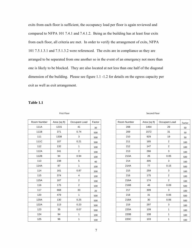
Occupancy Load, Exit Capacity and Exit Arrangement
The occupancy load was calculated for each space in the building. This was done
in accordance with NFPA 101 Table 7.3.1.2. The occupant load gives the minimum
amount of people that will occupy that particular space at any time. A comparison must
then be made to determine if the exit capacity of the floor is sufficient for the occupant
load of the floor. Table 1.1 gives the calculated occupancy load for each space on the
floor. Each floor was then totaled to give the total occupant load. The total occupant
load of the floor was then compared to the exit capacity of the same floor. Exit capacity
of each egress (circled in red) was calculated using NFPA 101 Table 7.3.3.1. Each exit
was measured and then divided by the factor given in the table. From this, the exit
capacity from each egress can be determined. In order to determine if the number of
7
exits from each floor is sufficient, the occupancy load per floor is again reviewed and
compared to NFPA 101 7.4.1 and 7.4.1.2. Being as the building has at least four exits
from each floor, all criteria are met. In order to verify the arrangement of exits, NFPA
101 7.5.1.3.1 and 7.5.1.3.2 were referenced. The exits are in compliance as they are
arranged to be separated from one another so in the event of an emergency not more than
one is likely to be blocked. They are also located at not less than one half of the diagonal
dimension of the building. Please see figure 1.1 -1.2 for details on the egress capacity per
exit as well as exit arrangement.
Table 1.1
First Floor Second Floor
Room Number Area (sq ft) Occupant Load Factor Room Number Area (sq ft) Occupant Load Factor
111A 1215 41 30 208 1464 29 50
111B 371 0.74 500 209 1572 31 50
111 1338 3 500 210 929 19 50
111C 107 0.21 500 211 165 2 100
112 132 1 100 212 147 2 100
112A 241 2 100 213 266 3 100
112B 94 0.94 100 213A 26 0.05 500
113 238 5 40 214 305 3 100
114A 87 1 100 214A 77 0.15 500
114 161 0.87 200 215 259 3 100
115 374 4 100 216 175 2 100
115A 167 2 100 216A 174 2 100
116 175 2 100 216B 46 0.09 500
117 668 33 20 217 309 3 100
120 479 1 500 218 31 0.06 500
120A 130 0.25 500 218A 30 0.06 500
122A 113 0.23 500 219 297 3 100
123 35 0.07 500 220A 109 1 100
124 94 1 100 220B 108 1 100
125 96 1 100 220C 103 1 100
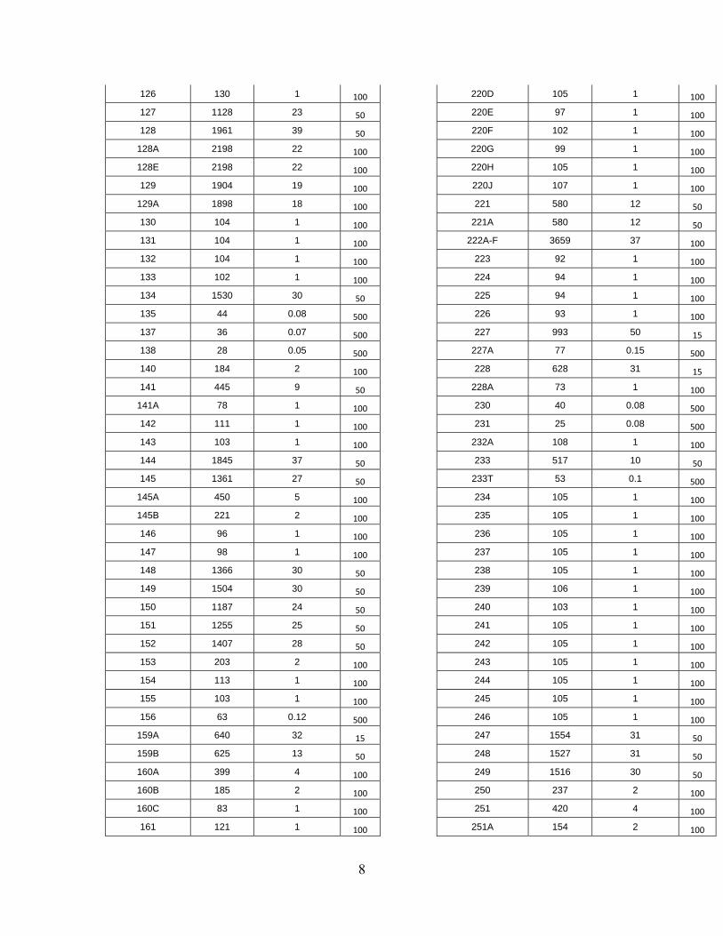
8
126 130 1 100 220D 105 1 100
127 1128 23 50 220E 97 1 100
128 1961 39 50 220F 102 1 100
128A 2198 22 100 220G 99 1 100
128E 2198 22 100 220H 105 1 100
129 1904 19 100 220J 107 1 100
129A 1898 18 100 221 580 12 50
130 104 1 100 221A 580 12 50
131 104 1 100 222A-F 3659 37 100
132 104 1 100 223 92 1 100
133 102 1 100 224 94 1 100
134 1530 30 50 225 94 1 100
135 44 0.08 500 226 93 1 100
137 36 0.07 500 227 993 50 15
138 28 0.05 500 227A 77 0.15 500
140 184 2 100 228 628 31 15
141 445 9 50 228A 73 1 100
141A 78 1 100 230 40 0.08 500
142 111 1 100 231 25 0.08 500
143 103 1 100 232A 108 1 100
144 1845 37 50 233 517 10 50
145 1361 27 50 233T 53 0.1 500
145A 450 5 100 234 105 1 100
145B 221 2 100 235 105 1 100
146 96 1 100 236 105 1 100
147 98 1 100 237 105 1 100
148 1366 30 50 238 105 1 100
149 1504 30 50 239 106 1 100
150 1187 24 50 240 103 1 100
151 1255 25 50 241 105 1 100
152 1407 28 50 242 105 1 100
153 203 2 100 243 105 1 100
154 113 1 100 244 105 1 100
155 103 1 100 245 105 1 100
156 63 0.12 500 246 105 1 100
159A 640 32 15 247 1554 31 50
159B 625 13 50 248 1527 31 50
160A 399 4 100 249 1516 30 50
160B 185 2 100 250 237 2 100
160C 83 1 100 251 420 4 100
161 121 1 100 251A 154 2 100
9
162 117 1 100 251B 146 1 100
163 117 1 100 252 618 12 50
164 113 1 100 252A 1459 29 50
165 113 1 100 252B 1365 27 50
166A 182 2 100 252C 1175 24 50
166 325 3 100 252D 1723 34 50
167 538 11 50 252E 1767 35 50
167A 45 0.45 100 252F 1329 27 50
168 152 2 100 252G 48 0.09 500
169 194 2 100 253 107 2 50
170 161 2 100 254 107 2 50
170A 191 2 100 255 111 2 50
171A 559 28 20 256 76 1 100
171 1488 99 15
171B 102 1 100 Max Occupancy 578
171C 635 42 15
Max Occupany 738 Exit Capacity 996
# of Exits 4
Exit Capacity 3025
# of Exits 11
Figur
re 1.1
10
Figurre 1.2
11
12
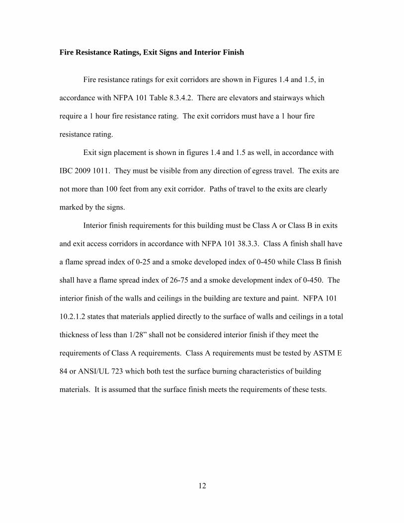
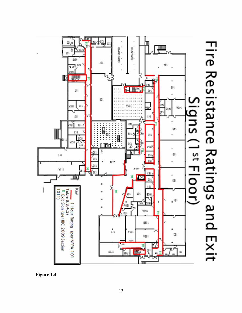
Fire Resistance Ratings, Exit Signs and Interior Finish
Fire resistance ratings for exit corridors are shown in Figures 1.4 and 1.5, in
accordance with NFPA 101 Table 8.3.4.2. There are elevators and stairways which
require a 1 hour fire resistance rating. The exit corridors must have a 1 hour fire
resistance rating.
Exit sign placement is shown in figures 1.4 and 1.5 as well, in accordance with
IBC 2009 1011. They must be visible from any direction of egress travel. The exits are
not more than 100 feet from any exit corridor. Paths of travel to the exits are clearly
marked by the signs.
Interior finish requirements for this building must be Class A or Class B in exits
and exit access corridors in accordance with NFPA 101 38.3.3. Class A finish shall have
a flame spread index of 0-25 and a smoke developed index of 0-450 while Class B finish
shall have a flame spread index of 26-75 and a smoke development index of 0-450. The
interior finish of the walls and ceilings in the building are texture and paint. NFPA 101
10.2.1.2 states that materials applied directly to the surface of walls and ceilings in a total
thickness of less than 1/28” shall not be considered interior finish if they meet the
requirements of Class A requirements. Class A requirements must be tested by ASTM E
84 or ANSI/UL 723 which both test the surface burning characteristics of building
materials. It is assumed that the surface finish meets the requirements of these tests.
Figurre 1.4
13
Figur
re 1.5
14
15
Occupant Characteristics
The main use of this building is labs/classrooms as well as professors’ offices.
The density in the labs should be relatively low as space is allotted for work areas. The
offices are sized to be large enough for one person. The larger labs and classrooms have
at least two exits therefore allowing a quick egress.
Since this building is located on a college campus, it is assumed that the age
range of the majority of the occupants will be young adults. The occupants should be
relatively familiar with the layout of the building as they visit it on a daily basis. Also, as
college takes a while to complete, the occupants may visit the same building for a number
of years. I would therefore expect the occupants to be very familiar with the building
layout. I also expect the occupants of the building to be alert, as it is not used for
sleeping.
The amount of responsibility of the occupants should be relatively low due to the
fact that this is an office and classroom setting. Most of the belongings of the occupants
should be relatively close to them and easy to gather. They will not have much
responsibility for the building itself. In most cases I would expect the occupants to grab a
backpack or laptop and then be ready to evacuate.
Social affiliation between classmates and teachers will likely have an effect on
egress time. Friends will likely gather with each other before making egress. Teachers
may also try to facilitate the evacuation of students, likely keeping them in a group as a
means of accountability.
The commitment of the occupants will also likely add time to egress. Students
will not react to an alarm immediately as they will likely be involved in lecture or lab
16
activity. An unwillingness to break from this activity and assumption that it is a false
alarm can significantly delay egress.
I would expect the occupants to be physically able to get around on their own and
require little assistance otherwise. They should be able to maintain an average walking
speed of 1 meter/sec on flat ground and an average of .5 meter/sec on stairs. I would also
believe that their cognitive ability would be above average as they are in college or
teaching in a college.
Pre-Movement and Movement Times
Taking into account the occupant characteristics above I would expect a relatively
quick evacuation time. It is necessary to take into account that all rooms will not be
occupied at all times. This decreases the amount of people that may need to evacuate at
any given time.
Time to detection in this building should be relatively short due to the fact that
there are always people moving around in this building and it is not used for sleeping.
Students and teachers are constantly entering and exiting classrooms, bathrooms and labs.
From ignition of a fire, I would predict no more than thirty seconds for detection to occur.
Reaction time of the occupants is again something I would consider to be
relatively short. Since the occupants are awake and alert, it should not take much time to
decide to leave. I would estimate around 30 seconds maximum to take action. This is
based on the SFPE Handbook where pre-movement times are taken from a large
department store.
17
Pre-evacuation activity time may be longer than reaction time but still should be
much less than occupants of a residence. Most of the occupants’ valuables are kept in
briefcases or backpacks that are easily packed and ready to go. Teachers and students
may take time to gather and try to stay together while making egress.
Travel time in this building should be considered to be under normal conditions
with density not being a factor. Most occupants will be young adults. Using this
assumption, from Table 4.2.2 it can be gathered that the average walking speed is 1
meter/second on flat ground and .5 meter/second on stairs. Per Table 3-12.6 in the SFPE
Handbook, I would expect 3.0 seconds to open doors.
Hand Calculation of Egress Time
The following will show a calculation of the amount of time it will take to fully
evacuate the Walter Dexter Building (Building 34). Measurements of all stairwells as
well as doorways were taken directly from the building. All assumptions are listed
below. All equations were taken from the NFPA fire protection handbook.
Analysis of Building 34 Please see Figure 1.1 and 1.2 for exit locations. North is assumed to be at the right of the page. Exit stairwells are indicated with a red square and exits are indicated with a red circle. 2nd Story - Stairwell widths from North and going clockwise to West are 44”, 59”, 60” and 58”. The respective door widths are 59”, 59”, 63” and 41”. Two exits give access to the ground floor and have no stairs. Their widths are 66” and 59”. 1st Story – Exit widths from North and going clockwise to West are 70”, 72”, 36”, 41” 36”, 36” and 72”.
18
Assumptions All occupants start egress at the same time. They will use all facilities in optimum balance. Stair risers are 7” tread is 11”. Fs=Fsmax . Floor area = 39000 sq ft. 12ft ceilings. Occupants = 650 per floor. 4’x 8’ landing on floor. Density =.175 persons/sq ft Flow of Stairways Boundary Layer = 6” on each side (Table 4.2.3) Stairway effective width = 32”, 47”, 48” and 46” respectively Doorway Effective width (stairwells) = 47”, 47”, 51” and 29” respectively Fs=Fsmax = 18.5 people/min/ft (Table 4.2.7) Fc= Fs * We (Eqn. 4) Fc = 18.5 * 2.67’= 49.3 people/min for 44” stairs Fc = 18.5 * 3.91’ =72.4 people/min for 59” stairs Fc = 18.5 * 4.0’ = 74 people/min for 60” stairs Fc = 18.5 * 3.8’ = 70.3 people/min for 58” stairs Flow of Doors Boundary Layer = 6” on each side (Table 4.2.3) Doorway effective width (2nd Story) = 54” and 47” respectively
Doorway effective width (1st Story) = 58”, 60”, 24”, 29”, 24”, 24” and 60” respectively
Fs=Fsmax = 24 people/min/ft (Table 4.2.7) Fc= Fs * We (Eqn. 4)
2nd Story Fc = 24* 4.5’ = 108 people/min for 66” door Fc = 24 * 3.9’ = 93.6 people/min for 59” door 1st Story
Fc = 24 * 4.8’ = 115 people/min for 70” door Fc = 24 * 5.0’ = 120 people/min for 72” door Fc = 24 * 2.0’ = 48 people/min for 36” door Fc = 24 * 2.4’ = 57.6 people/min for 41” door Fc = 24 * 2.0’ = 48 people/min for 36” door Fc = 24 * 2.0’ = 48 people/min for 36” door Fc = 24 * 5.0’ = 120 people/min for 72” door Speed of Stairway Flow (stairways limiting flow) S=k-akD (Eqn 1) k= 212 for stairs and 275 for corridors, a = 2.86 (Table 4.2.4) S=196-(2.86*212*.175) = 90 ft/min for travel speed down stairs Travel Distance (stairways limiting flow) Between floors = 12’ * 1.85 (Table 4.2.5) = 22.2’ on stairs + 8’= 30.2’ Travel Time
19
30.2 ft / 90ft/min = .33 min/floor Building Evac Times 2nd Floor - 49.3 people/min for 44” stairs 72.4 people/min for 59” stairs 74 people/min for 60” stairs 70.3 people/min for 58” stairs + 70.3 people/min for 58” stairs 108 people/min for 66” door 93.6 people/min for 59” door 537.9 people/min can evacuate from second floor 650 people / 537.9 people/min = 1.20 min 1.20 min + .33min = 1.53 min to evacuate
1st Floor - 115 people/min for 70” door 120 people/min for 72” door 48 people/min for 36” door + 57.6 people/min for 41” door 48 people/min for 36” door 48 people/min for 36” door 120 people/min for 72” door 557 people/min can evacuate from 1st floor 650 people / 557 people/min = 1.16 min to evacuate 1.16 + 1.53 +.5 (premovement) + .5 (detection) = 3.7 min = total evac time
20
Pathfinder
The evacuation simulator Pathfinder yields the following results. 2.63 minutes + .5 (premovement) + .5 (detection) = 3.63 min = total evac time This is based on 1300 occupants spread at random throughout the building. Features
such as fixed seating and exit only rooms were added to classrooms where applicable.
This figure compares well with the hand calculation yielding a difference of only four
seconds.
Uses and Limitations
This analysis of the evacuation time of this building is based on loose figures. It
is near impossible to calculate the population density due to many factors. It is
impossible to determine where people will go when an emergency occurs. Most will
often try to exit the way they entered. This can greatly increase the density at this exit
and therefore decrease the density at other exits.
Given the use of this building as classrooms, offices and labs, it makes it more
difficult to determine the density as not all rooms will be occupied at all times. The
occupant load of the room cannot be accurately determined because students tend to skip
class and classes can be canceled or held at other locations. Office hours can be canceled
as well.
One major assumption made by this calculation is that all exits will be available in
the event of an emergency. A fire is likely to shut down at least one or more exits due to
21
location and the presence of the products of combustion. Again, this will change the
density of the population using exits.
The use of this gives the designer an opportunity to calculate the effective widths
of doors and stairways. It also gives an estimation of evacuation times. By factoring
different densities, a designer can see how their design will play out in evacuation times.
It can be used as a basis to determine stairway and exit widths base on expected occupant
loads. This gives the opportunity to increase or decrease the widths and see what the
calculated egress time will be.
It should be noted that in this building the first floor and second floor exits do not
coincide with each other. Second floor exits (for the most part) cannot be used by first
floor occupants. This is due to the fact that a majority of the exits are stairwells that are
located outdoors. The midline of the building is located approximately six feet above
ground level at the front of the building. This makes a couple of the exits accessible to
the outside with the use of a ramp. The rear of the building takes on a true two story
above ground level stance.
Tenability Performance Criteria
The objectives summarized in the Life Safety Code Section 4.2 state that:
1) A structure shall be designed, constructed, and maintained to protect occupants who are not intimate with the initial fire development for the time needed to evacuate, relocate or defend in place.
2) Structural integrity shall be maintained for the time needed to evacuate, relocate or defend in place occupants who are not intimate with the initial fire development.
3) Systems utilized to achieve the goals of #1 shall be effective in mitigating the hazard or condition for which they are being used, shall be reliable, shall be
22
maintained to the level at which they were designed to operate and shall remain operational.
It has been calculated that it will take approximately three minutes to evacuate the
Walter Dexter Building given normal occupant loading. This time serves to show that
the building is designed with the adequate number of exits and exit capacities to allow
occupants to escape. The building is designed with all rooms and offices located directly
off of main exit corridors. This is the design feature that allows for quick egress from the
building in the event of an emergency. Rooms with larger occupant capacities offer at
least two exits.
The Walter Dexter Building’s (Building 34) most noticeable design feature is the long
corridors leading to exits. Construction along these corridors must be at least one hour
fire resistive construction according to LSC Table 8.3.4.2. It was calculated that the
egress time for the entire building is approximately three minutes. This design feature
meets the requirements of #1 above. Also, all stairways must be of 1 hour fire resistive
construction. Again this exceeds the requirements for the safe egress time as calculated.
There are no suppression or smoke evacuation systems installed in this building.
Being as such, the only items that must be maintained are the clear corridors and
stairways. As long as no obstructions are introduced (ex. displays, trash cans etc.), egress
times should not be hampered.
A difficulty with this building is determining the path that smoke will take and how it
will affect the occupants. The location of a fire will determine how smoke travels
through the building. If it starts near a stairwell, for instance, the smoke will likely travel
to the second floor and have an effect on occupants there faster than occupants on the
23
first floor. A fire that starts near the end of a corridor on the second floor will likely have
no effect on the first floor occupants for a long period of time.
Smoke will have a large impact on egress time as it can cause a decrease in vision and
an increase in breathing difficulty thereby reducing walking speed and increasing
exposure time. Although the long corridors allow for easy paths of travel, they also act as
channels for smoke. The long corridors may cause occupants to become confused or
disoriented and unable to distinguish which exit is closest to them or which direction will
lead them to safety. As stated before it is difficult to account for all scenarios such as fire
size and location. This will determine which occupants are affected first and how they
will respond. Fire modeling is the best way to deal with a majority of scenarios.
For the simulation, tenability criteria that must be met are a temperature not
exceeding 65 C, visibility must remain above 10 meters and CO concentration must not
exceed 1200 parts per million. These properties will be evaluated later in this report.
24
Notification
Fire Alarm System
The Dexter building is currently protected by a Digital Monitoring Products Inc.
system. The issue number of the system is AH-9874. The system consists primarily of
manual pull stations connected to audible alarms. This is due to the fact that the building
was constructed during the 1940’s. However, heat detectors have been added to room
111A. This is a mercantile occupancy which is currently occupied by Subway
Restaurant. These heat detectors were installed there as the room used to house vending
machines. The fire detection system relies primarily on occupants sounding the alarm.
The fire alarm control panel is located on the ground floor of the building,
adjacent to the electrical room (Room 157). The main keypad behind the enclosure is a
Fire Command 690F model. Cal Poly is currently in the process of updating all alarm
systems to a Notifier system. This building is one of a few remaining with a Digital
Monitoring Products system.
Detection Devices
As previously mentioned, the only fire detection devices in the building are spot
type, ordinary heat detectors (assumed, 135-174F). They protect the Subway Restaurant,
located on the first floor of the building. These detectors are listed as a one-time use
detector and therefore are not inspected. They are built with a fusible link which is
designed to melt when the temperature is increased. When this link melts, the alarm will
be set off inside the building. Subway currently occupies the only room with the heat
25
detectors. This seems to be a good fit as refrigeration equipment as well as ovens maybe
in operation when the building is unoccupied.
There are no other detection devices in the building. This is likely due primarily
to the fact that the building is rarely occupied to capacity due to varying class times. It is
also likely due to the fact that the cost of renovating the alarm does not make economic
sense. The goal is to have the entire campus monitored by one system manufacturer. I
was informed by the risk manager that this is one of the few buildings that is not under a
Notifier system. They are hoping to renovate it and switch the fire alarm system over to a
Notifier system in the next 5 to 10 years. The following figures (1.6 – 1.7) give the
locations of fire alarm pull systems as well as the signal device locations.
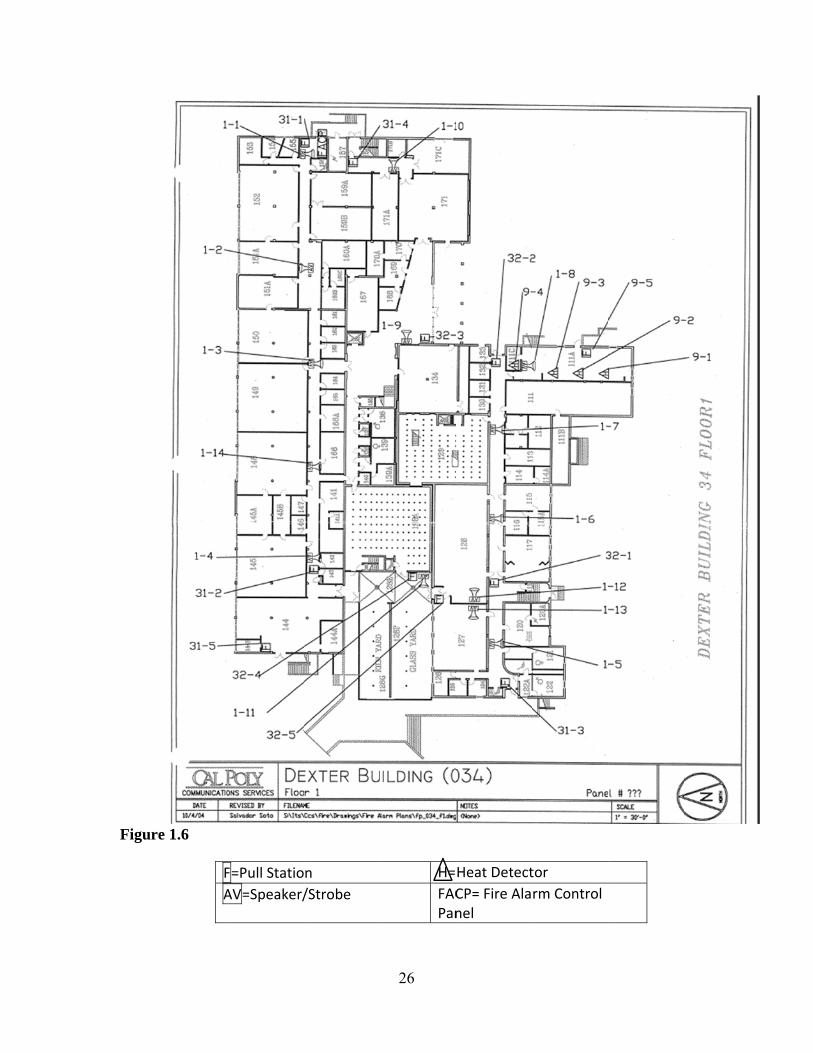
Figur
re 1.6
F
A
F=Pull Statio
AV=Speaker/
n
/Strobe
26
H=
FACPan
Heat Detect
CP= Fire Alanel
tor
rm Control
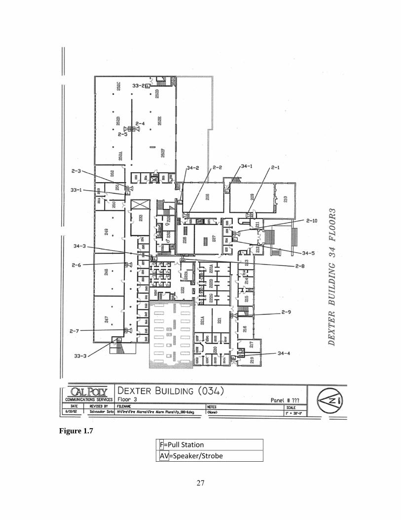
Figur
re 1.7
F=Pull St
AV=Spea
27
ation
aker/Strobe
28
Detection Device Placement
According to NFPA 72 Chapter 17.4, the initiatiating devices shall not be
installed in inaccessbile areas, and shall beinstalled in a manner that provides
accessibility for periodic maintenance. The heat detectors that are installed in room 111A
are easily accessible with a ladder for maintenance. However, these are a one time use
device so no maintenance is required. Chapter 17.5 forbids the detectors to be recessed
into the mounting surface. Upon inspection, it is evident that these detectors are not
recessed into the mounting surface.
Since this is the only room covered by detection devices, Chapter A17.5.3.2 of
NFPA 72 applies. This states that if there are no detectors in the room or area of fire
origin, the fire could exceed the design objectives before being detected by remotely
located detectors. When coverage other than total coverage is required, partial coverage
can be provided in common areas and work spaces such as corridors, lobbies, storage
rooms, equipment rooms and other tenantless spaces. The intent of selective coverage is
to address a specific hazard only.
Where a specific area is to be protected, all points within that area should be
within .7 x the adjusted detector spacing for spot-type detectors as required by 17.6.3.
The ceiling height of room 111A is approximately 12 feet. There are no projections
coming down from the flat ceiling and no partitions in the room. In accordance with
Chapter 17.6.3.5.1 which states on ceilings 10 feet to 30 feet high, heat detector spacing
shall be reduce in accordance with Table 17.6.3.5.1 prior to any additional reductions for
beams, joists, or slope where applicable. Based on this chart, a ceiling height up to and
including 12 feet has a factor of .91 to be multiplied by the listed detector spacing. It is
29
assumed that these detectors have a listed spacing of 30 feet. This means that 30 x .91
gives a spacing of 27.3 feet. There are three detectors that cover a length of
approximately 65 feet. So based on the fact that 27.3x3= 81.9 the coverage area is
approximately 82 feet. This gives an adequate amount of detectors to cover the length of
the room. The width of the room is approximately 20 feet so again the number of
detectors is adequate based on a spacing of 27.3 feet.
As previously mentioned, the building is mostly outfitted with manual actuated
alarm initiating devices. According to NFPA 72 Chapter 17.14 manual pull stations
should be red in color and the background should be of a contrasting color. They should
be mounted between 42 and 48 inches above the floor and be unobstructed. They are to
be mounted within 60 inches of each doorway that exits the building. They will be
located within 200 feet of each other on the same floor. A walkthrough and measurement
of the building provided all of the aforementioned criteria to be true.
Scenario
Since there are only detection devices in the occupancy which is now a Subway
restaurant, a fire would have to propagate there for the detection devices to most quickly
respond to a fire. In this example, we will assume a polyethylene wastebasket filled with
12 milk cartons (Table B.2.3.2.6.2d) that is against the wall on the edge of the room. The
room measures approximately 20 x 65 feet. Ambient temperature is assumed to be 20 C
and the height is 12 feet or 3.65 meters.
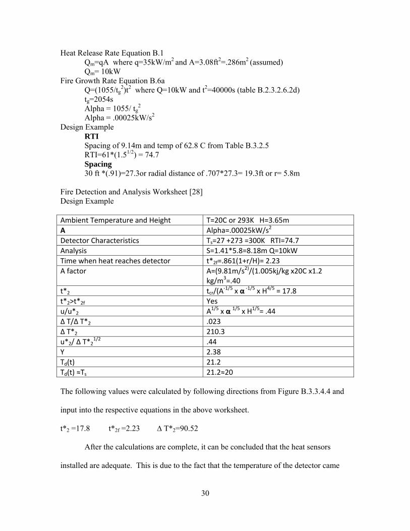
30
Heat Release Rate Equation B.1 Qm=qA where q=35kW/m2
and A=3.08ft2=.286m2 (assumed) Qm= 10kW Fire Growth Rate Equation B.6a Q=(1055/tg
2)t2 where Q=10kW and t2=40000s (table B.2.3.2.6.2d) tg=2054s Alpha = 1055/ tg
2 Alpha = .00025kW/s2 Design Example
RTI Spacing of 9.14m and temp of 62.8 C from Table B.3.2.5 RTI=61*(1.51/2) = 74.7
Spacing 30 ft *(.91)=27.3or radial distance of .707*27.3= 19.3ft or r= 5.8m Fire Detection and Analysis Worksheet [28] Design Example Ambient Temperature and Height T=20C or 293K H=3.65m
Α Alpha=.00025kW/s2
Detector Characteristics Ts=27 +273 =300K RTI=74.7
Analysis S=1.41*5.8=8.18m Q=10kW
Time when heat reaches detector t*2f=.861(1+r/H)= 2.23
A factor A=(9.81m/s2)/(1.005kj/kg x20C x1.2 kg/m3=.40
t*2 tcr/(A‐1/5 x α ‐1/5 x H4/5 = 17.8
t*2>t*2f Yes
u/u*2 A1/5 x α 1/5 x H1/5= .44
∆ T/∆ T*2 .023
∆ T*2 210.3
u*2/ ∆ T*21/2 .44
Y 2.38
Td(t) 21.2
Td(t) ≈Ts 21.2≈20 The following values were calculated by following directions from Figure B.3.3.4.4 and
input into the respective equations in the above worksheet.
t*2 =17.8 t*2f =2.23 ∆ T*2=90.52
After the calculations are complete, it can be concluded that the heat sensors
installed are adequate. This is due to the fact that the temperature of the detector came
31
out slightly larger than the ambient temperature, but only marginally. One would expect
to see a much larger difference in Td(t) and Ts if the current spacing was clearly
inadequate. However, this can be attributed to rounding errors while solving the
problem.
Disposition, Supervisory and Trouble Signals
In order to reset the system the COMMAND key followed by 4 and 7 must be
pressed. The system will reset any smoke detectors and stop the flashing fire zone light if
it returns to normal. A user code must be entered in order to silence the alarm.
NFPA 72 3.3.240.6 defines a supervisory signal as a signal indicating the need for
action in connection with the supervision of guard tours, the fire suppression system or
equipment, or the maintenance features of related systems. Per the manufacturer’s
literature, there are three supervisory signals that this alarm system can generate. They
are Power Trouble, Phone Line and Battery. Power Trouble has two options one is the
type of trouble that occurred with your system and the second is an AC power problem.
Phone line will indicate a problem with either phone line 1 or 2. A battery signal will
indicate a problem with a low battery or the battery exceeding its life expectancy.
A trouble signal is displayed as a LED on the control panel. It will turn on when
there is a problem trying to communicate with the central system. It will also turn on
when there is a problem with the phone line. It will pulse (1 second off and 1 second on)
when there is a problem with the system. When this happens, it is advised to call for
service.
Notif
occup
Simp
numb
to NF
use o
office
Howe
occup
The a
Figur
fication Dev
As previo
pants using t
plex Grinnell
ber. Their lo
This build
FPA 18.4.1.1
of a visual no
es. It would
ever, the vis
pancies have
audible warn
re 1.8
vices
ously mentio
the alarm sy
l combinatio
ocations are n
ding consists
1 an average
otification ap
d be a rare oc
ual notificat
e an average
ning device m
oned, the buil
stem to alert
on horn and s
noted on Fig
s of both aud
e ambient sou
ppliance. Th
ccasion wher
tion can help
ambient sou
must have a
32
lding alarm
t others of a
strobe (Figur
gures 1.6 and
dible and vis
und level gre
he building c
re the sound
p with those
und level of
sound level
system prim
fire. The no
re 1.8) simil
d 1.7 of this
sual notificat
eater than 10
consists mos
level would
who are hea
55dB accord
at least 15dB
marily relies o
otification de
lar to a 4903
report.
tion devices
05dB shall r
stly of classr
d reach 105d
aring impaire
ding to Tabl
B above the
on the
evices are a
-9356 mode
. According
equire the
ooms and
dB.
ed. Business
le A.18.4.3.
average
el
g
s
33
ambient sound level or 5dB above the maximum sound level having a duration of at least
60 seconds, whichever is greater, measured 5 feet above the floor in the area required to
be served by the system in order to be in compliance with 18.4.3.1.
NFPA 18.4.8.1 states that wall mounted audible appliances shall have their tops
above the finished floors at heights of not less than 90 inches and below the finished
ceilings at distances of not less than 6 inches. These devices installed in this building are
combination audio visual appliances so this code does not apply to them. 18.4.8.3 states
that if combination audible/visible appliances are installed, the location of the installed
appliance shall be determined by the requirements of 18.5.4 which is described below.
The visual requirements for these combination devices are given in 18.5. They
must be located and must be of a type, size, intensity and number so that the operating
effect of the appliance is seen by the intended viewers regardless of the viewer’s
orientation. The flash rate shall not exceed 2 flashes per second and have a duration of .2
seconds. The lens for the light must be mounted between 80 and 96 inches above the
finished floor.
All of the appliances in the building met this requirement. However, it is
important to note that most signaling devices are located in the main corridors of the
building. This means that there should be a strobe mounted approximately every 40 feet
in the corridor in accordance with 18.5.4.3 which sets the standard for spacing in rooms.
There is an appliance located approximately every 60 feet. The alternative to this spacing
in the corridor is that a minimum illumination of .0375 lumens/ft2 is provided where
visible notification is required in accordance with 18.5.4.5. For the purposes of this
34
report, it is impractical to measure the intensity of light in the corridor with the alarm
functioning.
As far as the notification in rooms that do not contain a combination notification
device, the only means occupants will be alerted is through audible tones. This violates
the ADA Advisory 215.1 which states that unlike audible alarms, visible alarms must be
located within the space they serve so the signal is visible. Occupants will have to be
warned by others that there is an emergency.
Power Supply
Power supply requirements are made using literature from current Simplex
combination notification devices. Due to the age of the building and the system, it was
not possible to find requirements for the installed devices without physically removing
them from the wall. The combination device used is a Simplex TrueAlert wall mount
with a speaker and strobe combination. The maximum voltage and current are 24 VDC
and 63mA respectively. The speakers draw ½ W of power for a decibel rating of 81 at 10
ft. Total current drawn per device is based on similar combination notification devices.
Figur
Figur
stand
alarm
re 1.9
re 2.0
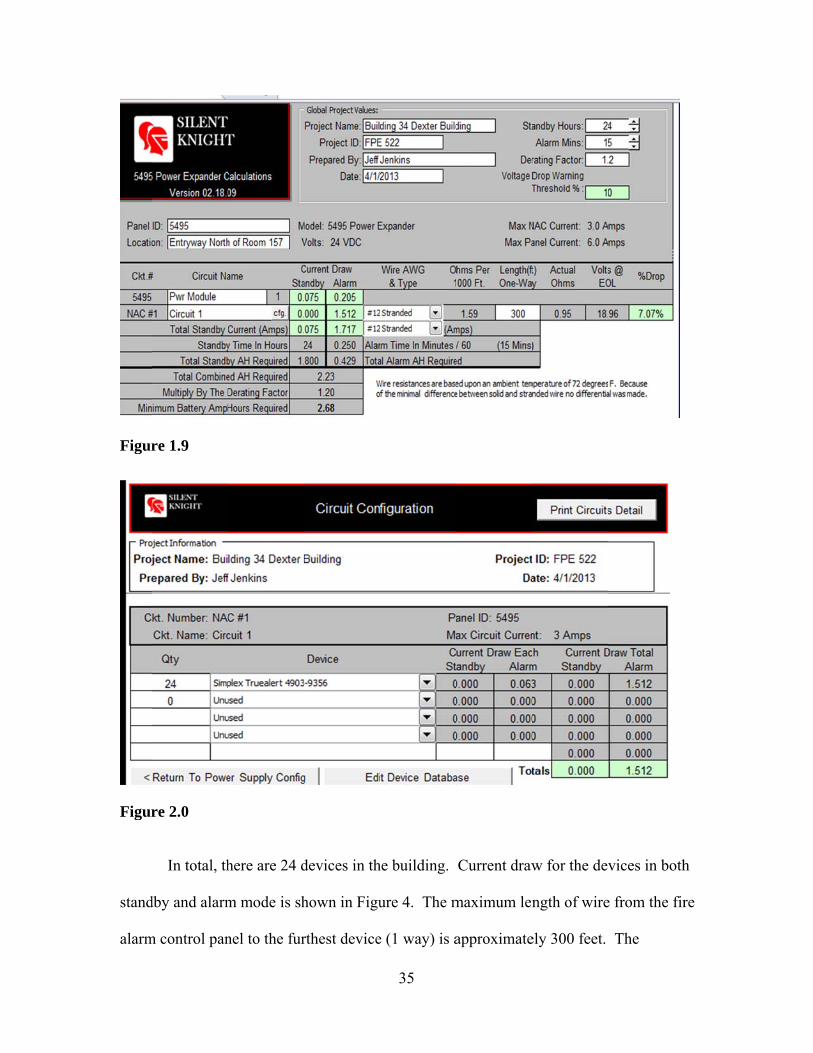
In total, th
dby and alarm
m control pan
here are 24 d
m mode is sh
nel to the fur
devices in th
hown in Figu
rthest device
35
he building.
ure 4. The m
e (1 way) is a
Current draw
maximum len
approximate
w for the dev
ngth of wire
ely 300 feet.
vices in both
e from the fir
The
h
re
36
resistance is calculated in Figure 3. It is assumed that the secondary system must alarm
for 15 minutes and have a 24 hour standby time. The minimum battery amp hours
required was found to be 2.68.
The DMP Fire Alarm Control Panel requires 24 volts and 4 amps maximum. It
is backed up by two 12 volt batteries each rated at 7.5 amp hours. The secondary power
supply for the simplex devices consists of two 12 volt batteries with a capacity of 24 amp
hours. Being as the requirement for the system has been calculated to be a minimum of
2.68 amp hours the 24 amp hour capacity more than meets this requirement.
A reason for the possible discrepancy between these two values is that neither the
alarm standby time in the event of a power failure nor the alarm times are actually
known. At the time of installation, these requirements may have varied from the values
used for this calculation. Also, the actual amperage drawn for the combination devices
has been approximated based on other similar devices.
Maintenance and Testing
The alarm system in the Dexter building undergoes annual testing by Deep Blue
Integration. This is in compliance with NFPA 14.2.1.1. Deep Blue provides a testing
schedule of each building as 14.2.5.2 states that all occupants must be notified. An
inspection report of the findings is given back to the EHS office when the testing is
complete.
The device’s name, location and serial number (if applicable) is posted on this
report. Each device is judged as either passing, failing or not tested. Any discrepancies
are listed at the end of the report. The name of the tester and signature is required at the
37
end of the report. The report states “all tests performed in accordance with California
Code of Regulations Title 19, Section 1.09(a); NFPA 72 CH 7, Sect. 7-2; NFPA 72,
Table 7-8.2; and NFPA 72, Table 7-3.2.”
Testing procedures involve testing the batteries with a load tester. Audio and
visual alarms are tested by activating the alarm notification devices. Confirmation of
proper operation of the audible and visual alarms must then be obtained. The audible
alarms are to be verified that they are at least 15db above the ambient sound levels. The
tester must then verify the reporting at the panel. Correct operation of the speakers and
reporting to the panel must also be tested. The manual pull stations must be checked for
proper operation and checked for reporting at the panel. The heat detectors in this
building are one time use and therefore are not tested.
38
Construction Classification
The building is a mixed occupancy building and is two stories in height. The total
area of the first floor is 39,062 square feet and the total area of the second floor is 31,716
square feet (See Table 1). Based upon Table 503 in the International Building Code, the
building can be either Type I A or B construction for all occupancy classes. An assembly
occupancy makes up the greatest portion of the building. This sets the standard for
building size (508.2.1, 508.2.3). It also precludes the structure from being typed as
anything other than a Type 1 A or B construction classification in accordance with the
2009 International Building Code (Table 503). There are uninsulated steel I beams that
are used for roof rafters in the construction of this building. Typically this would cause
the structure to be typed as Type II or III. However, there is a steel lathe and plaster
which makes up the ceiling of the second story.
Construction Materials
The building is composed primarily of reinforced concrete. Upon inspection, all
exterior and interior load bearing walls are made of concrete. Columns were not found to
be present in the structure. This is likely due to the fact that it is only two stories in
height. Floors were found to be of concrete.
The structure is of tilt up construction. The main load bearing walls and floors
were installed first. Divisions between classrooms and offices were likely added after.
The construction materials of these partitions (non- load bearing walls) is drywall (5/8”
gypsum) over either steel or wood studs. It is assumed that standard stud spacing at
39
sixteen inches on center was used and stud size is approximately 2” x 4”. Stud material
could not be determined while inspecting the building.
The roof of the building is composed of concrete tile. There is a wood supporting
structure underneath consisting of plywood. The supports for the roof are made up of
steel I beams. The interior of the second story ceiling consists of a steel lathe and plaster.
Please see figure 2.1. The interior of the building consisted of concrete and gypsum
walls. The concrete and gypsum walls were both painted while the gypsum walls had an
added textured finish. The floor consists of tile over a concrete floor. The exterior of the
building was covered with a painted concrete finish.
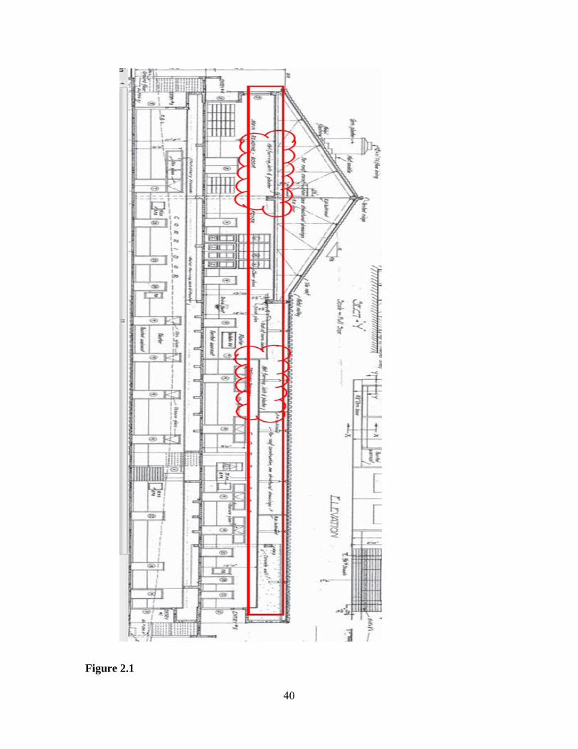
Figurre 2.1
40
41
Fire Resistance Ratings
The fire resistance ratings for a Type 1 A structure are as follows. The primary
structural frame must be of 3 hour fire resistance. There were no structural elements with
a sprayed on fire resistive coating located in the building. Interior and exterior bearing
walls must have this same 3 hour rating. The concrete construction should easily provide
for this rating. There were no exterior non load bearing walls in the structure. If I have
unknowingly miscategorized an exterior wall as load bearing, a fire resistance rating of
one hour would be required for the non-load bearing exterior wall. This is based on a
separation distance from adjoining structures of 10 to 30 feet and a group A occupancy in
accordance with Table 602. All interior non-load bearing walls and partitions are not
required to have a fire resistance rating. Floor construction must have a 2 hour rating.
The roof construction and secondary members must have a 1.5 hour rating. However, in
a group A occupancy, fire protection of structural members are not required but fire
treated wood must be used.
The fire resistance ratings for a Type 1 B structure are as follows. The primary
structural frame must be of 2 hour fire resistance. Interior and exterior bearing walls
must have the same 2 hour rating. Non-load bearing exterior walls must be one hour
rated based on Table 602, a group A occupancy and a 10 to 30 foot separation distance
from adjoining structures. Non-load bearing walls and partitions are not required to have
a fire resistance rating. The floor construction must have a 2 hour fire rating. The roof
and secondary members are allowed to have a 1 hour rating. However, in a group A
42
occupancy, fire protection of structural members is not required but fire treated wood
must be used.
Based upon the requirements for the structure to fall into either the Type I A or B
category, I would call this building a Type I B. The distinguishing feature between I A
and B is the fire resistance rating of the structural members of the roof. The steel lath and
plaster provides a one hour rating not a one and a half hour rating. The problem with
determining the construction type is that the building was constructed in 1948. There
were no codes around at the time. Therefore, the building most closely resembles a Type
IB. Although the members in the roof are not rated, they seem to be consistent with at
the time would be a noncombustible construction type.
The walls being of concrete, are relatively thick in size. This should increase their
fire resistance rating. It provides greater protection for the reinforcing steel members
inside the walls than would thinner walls. Even though no fire resistance rating is
required for the interior walls, they are comprised of 5/8” gypsum which should provide
at a minimum a one hour fire resistance rating. Any kind of fire in this structure would
be room contents. It would be difficult to foresee any part of the structure itself
becoming involved with fire. Failure of the non-load bearing walls can be expected but a
collapse of the structure due to fire would be highly unlikely.
43
Performance Based Tenability Analysis Introduction
For the performance based design and three criteria will be considered. The three
criteria are visibility, temperature, and carbon monoxide exposure. Based upon various
sources the temperature for tenability is approximately 65° C. The visibility for
tenability must remain above 10 meters. Carbon monoxide exposure must remain below
1200 parts per million.
Fire Scenario
After a walkthrough of the building and a review of the Pathfinder results, a likely
location for a fire was determined to be in room 252. Based on NFPA 101, a
combination of design fire scenario five and six are used. Design scenario five is a
slowly developing fire in close proximity to a high occupancy area. It addresses the
concerns regarding a relatively small ignition source causing a significant fire. Design
fire scenario six is the most severe fire resulting from the largest possible fuel load
characteristic of the normal operation of the building. It should also be noted that
through the use of Pathfinder, this room requires the longest time for exit of all occupants
when both exits were available. The location of this fire makes one exit inaccessible to
the occupants. This provided a unique opportunity to see how a fire in a room with the
longest egress time would affect the occupants. They should be noted that using
Pathfinder even with both exits the available only 2-3 occupants exited through the now
blocked exit.
44
Design Fire
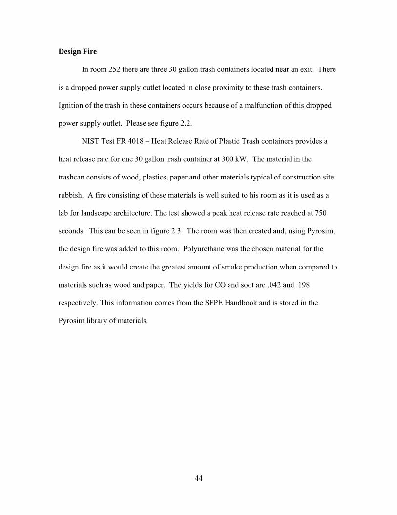
In room 252 there are three 30 gallon trash containers located near an exit. There
is a dropped power supply outlet located in close proximity to these trash containers.
Ignition of the trash in these containers occurs because of a malfunction of this dropped
power supply outlet. Please see figure 2.2.
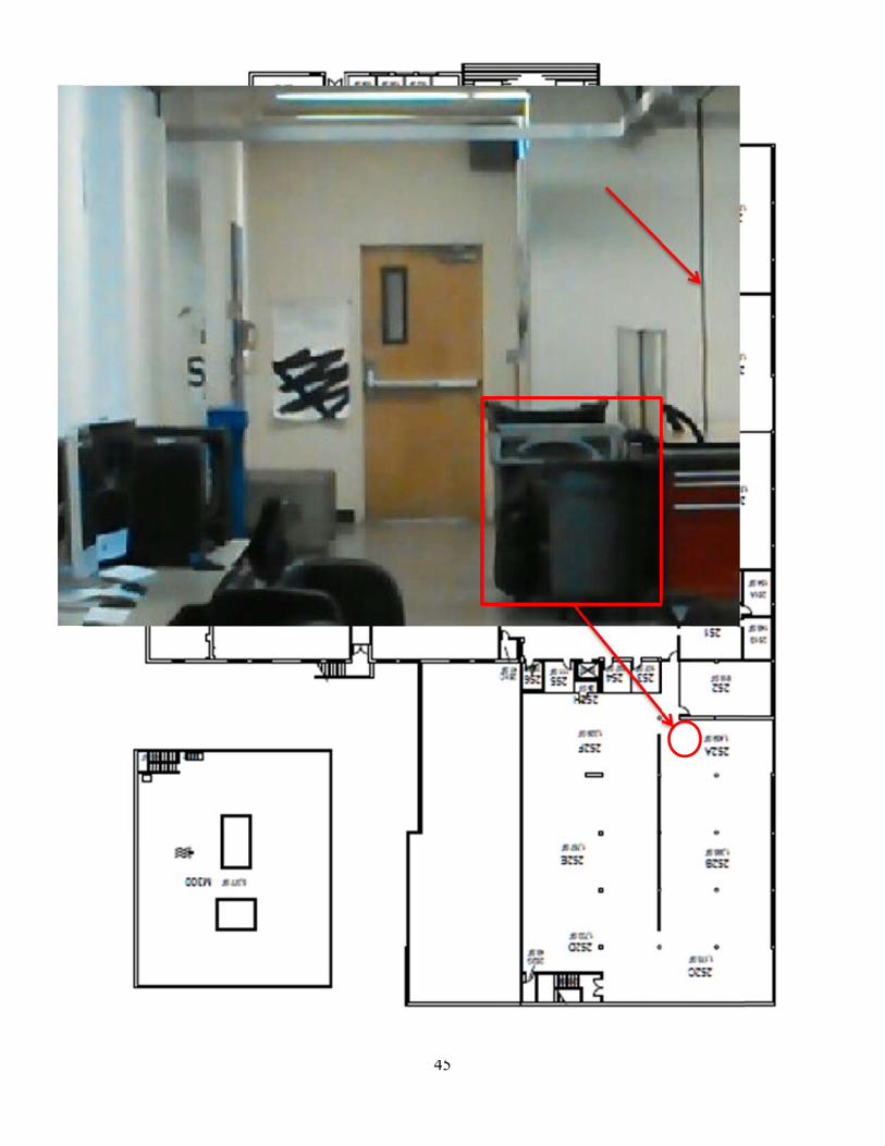
NIST Test FR 4018 – Heat Release Rate of Plastic Trash containers provides a
heat release rate for one 30 gallon trash container at 300 kW. The material in the
trashcan consists of wood, plastics, paper and other materials typical of construction site
rubbish. A fire consisting of these materials is well suited to his room as it is used as a
lab for landscape architecture. The test showed a peak heat release rate reached at 750
seconds. This can be seen in figure 2.3. The room was then created and, using Pyrosim,
the design fire was added to this room. Polyurethane was the chosen material for the
design fire as it would create the greatest amount of smoke production when compared to
materials such as wood and paper. The yields for CO and soot are .042 and .198
respectively. This information comes from the SFPE Handbook and is stored in the
Pyrosim library of materials.
Figuree 2.2
45
Figur
heat r
highe
Temp
used
from
rema
calcu
play a
re 2.3
It should b
release rate o
est heat relea
perature
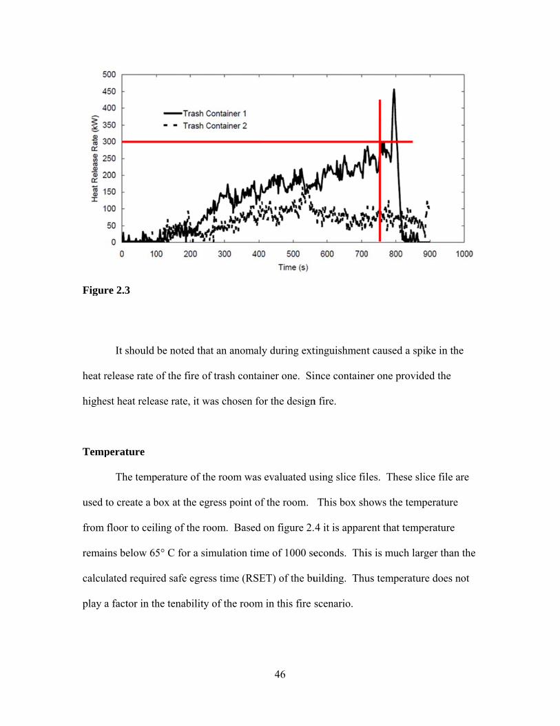
The temp
to create a b
floor to ceil
ins below 65
ulated require
a factor in th
be noted tha
of the fire of
ase rate, it w
erature of th
box at the eg
ling of the ro
5° C for a sim
ed safe egres
he tenability
at an anomaly
f trash conta
was chosen fo
he room was
ress point of
oom. Based
mulation tim
ss time (RSE
of the room
46
y during ext
iner one. Si
or the design
evaluated u
f the room.
on figure 2.
me of 1000 se
ET) of the bu
m in this fire s
tinguishment
ince containe
n fire.
using slice fil
This box sh
4 it is appar
econds. Thi
uilding. Thu
scenario.
t caused a sp
er one provi
les. These s
hows the tem
rent that temp
is is much la
us temperatu
pike in the
ded the
slice file are
mperature
perature
arger than the
ure does not
e
Figur
Carb
conce
atmo
escap
health
in hei
conce
may b
are en
conce
with
re 2.4
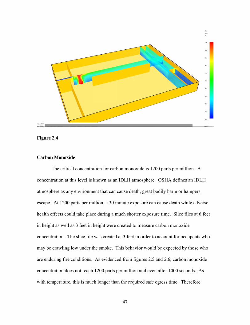
bon Monoxi
The critic
entration at t
sphere as an
pe. At 1200
h effects cou
ight as well
entration. T
be crawling
nduring fire
entration doe
temperature
de
cal concentra
this level is k
ny environme
parts per mi
uld take plac
as 3 feet in h
he slice file
low under th
conditions.
es not reach
, this is muc
ation for carb
known as an
ent that can
illion, a 30 m
ce during a m
height were
was created
he smoke. T
As evidence
1200 parts p
ch longer tha
47
bon monoxid
n IDLH atmo
cause death,
minute expos
much shorter
created to m
d at 3 feet in
This behavio
ed from figu
per million a
an the require
de is 1200 p
osphere. OS
, great bodily
sure can cau
r exposure tim
measure carb
order to acc
or would be e
ures 2.5 and
and even afte
ed safe egre
arts per mill
SHA defines
y harm or ha
use death wh
me. Slice fi
on monoxid
ount for occ
expected by
2.6, carbon
er 1000 seco
ss time. The
lion. A
an IDLH
ampers
hile adverse
iles at 6 feet
de
cupants who
those who
monoxide
onds. As
erefore
carbo
scena
Figur
Figur
on monoxide
ario.
re 2.5
re 2.6
e concentratiion is not a f
48
factor in the tenability off this room inn this fire
49
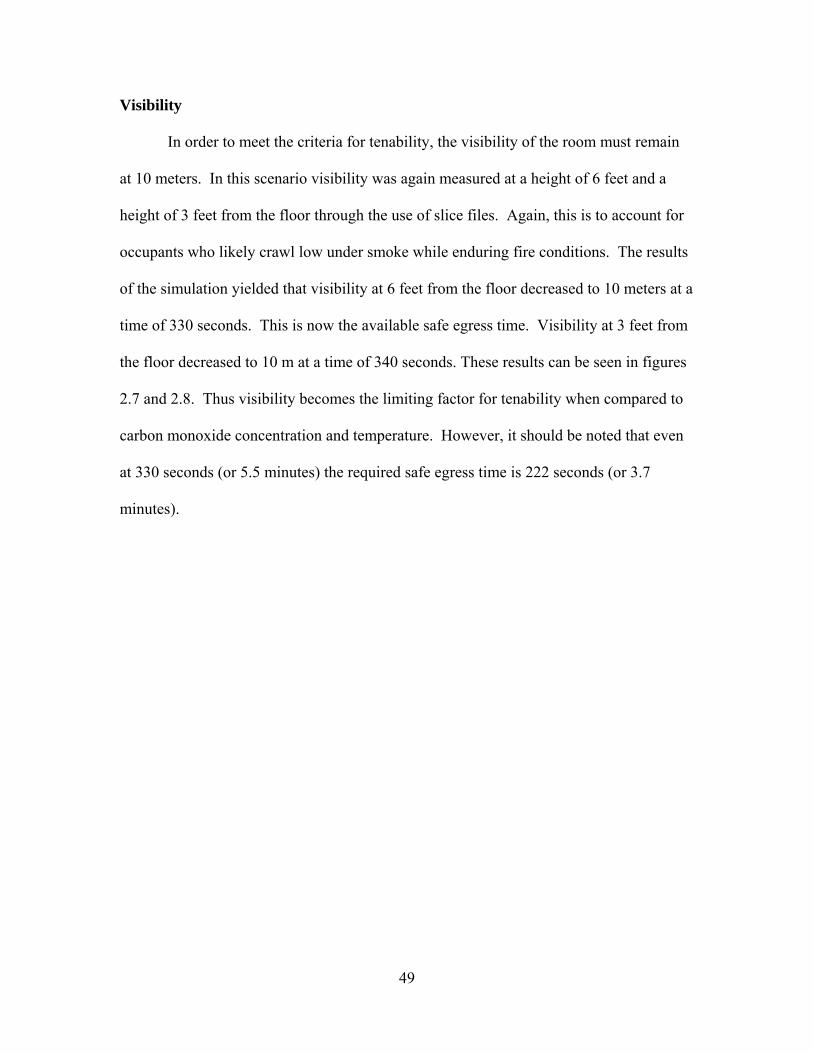
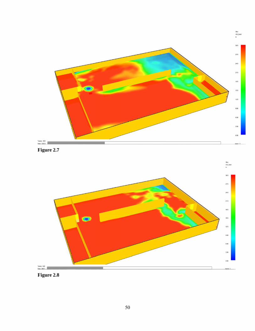
Visibility
In order to meet the criteria for tenability, the visibility of the room must remain
at 10 meters. In this scenario visibility was again measured at a height of 6 feet and a
height of 3 feet from the floor through the use of slice files. Again, this is to account for
occupants who likely crawl low under smoke while enduring fire conditions. The results
of the simulation yielded that visibility at 6 feet from the floor decreased to 10 meters at a
time of 330 seconds. This is now the available safe egress time. Visibility at 3 feet from
the floor decreased to 10 m at a time of 340 seconds. These results can be seen in figures
2.7 and 2.8. Thus visibility becomes the limiting factor for tenability when compared to
carbon monoxide concentration and temperature. However, it should be noted that even
at 330 seconds (or 5.5 minutes) the required safe egress time is 222 seconds (or 3.7
minutes).
Figur
Figur
re 2.7
re 2.8
50
51
Conclusion In this prescriptive egress analysis, it is found that the Walter P. Dexter Building
meets the necessary NFPA 101 requirements that were discussed in this report. The most
critical factor is egress capacity exceeding the occupant load. As calculated, the egress
capacity exceeds the occupant load for each floor. Paths of egress are clearly defined, the
arrangement is appropriate and the number of exits is sufficient.
The building seems to clearly meet the criteria for available safe egress time being
larger than required egress time. It is clear in the hand calculation above that it will take
approximately 3 minutes to evacuate the building. Based on this number the tenability of
the structure in the event of a fire seems adequate. Although the building is lacking
automatic sprinklers and smoke removal systems, the exit capacity and size of both
stairwells and doorways seem adequate to allow for safe egress. Another factor affecting
the tenability is the familiarity of the occupants with the building. It is frequented by
students and faculty who have repeat visits to the structure. This increases their
familiarity with the structure and therefore their ability to make quick egress in the event
of an emergency. They will be able to quickly locate the nearest exit and likely guide
others who are less familiar with the building.
The fire alarm system in the Dexter is a fairly old system relying on the occupants
for activation. There are no automatic suppression devices installed in the building. The
only detection devices in the building are located in one room which is currently a
Subway Restaurant. Spacing of these devices is adequate for the size of the room. The
number of heat detectors for the one room in which they are installed was found to be
accurate. The rooms are lacking visual notification devices. This is in conflict with
52
ADA Advisory 215.1 which states that unlike audible alarms, visible alarms must be
located within the space they serve so the signal is visible. Based on assumptions made
regarding notification device power requirements and wiring, the secondary power
supply was found to be ample. The system is tested annually in accordance with NFPA
72. All devices are checked for proper operation and reporting at the panel.
The Dexter Building on the Cal Poly, San Luis Obispo campus falls into the
category of Type 1 B construction based on the 2009 International Building Code. The
size and type of construction materials used are sufficient to give it the fire resistance
ratings required by the code. It is a mixed occupancy building but a group A occupancy
comprises at least 90% of it. Lecture halls compose the bulk of the occupancies within
the structures. Also, group A occupancies provide the highest requirements for fire
resistance. This is in accordance with life safety being a priority.
Performance based tenability criteria for the designed fire scenario is met by the
building. The designed fire scenario combines scenarios 5 and 6 from the NFPA Life
Safety Code. It is a slowly developing fire in the largest fuel load of the building in close
proximity to a high occupancy area. Three thirty gallon trash cans filled with materials
typically found on a construction site were used.
The required safe egress time from the hand calculation as well as the Pathfinder
simulation was found to be approximately 3.7 minutes. These values differed by only 4
seconds from each other. The fire does not hit a peak heat release rate for 12.5 minutes.
This allows the occupants plenty of time to escape. Of the three tenability criteria,
visibility is the only one that presents a problem at 330 seconds. This is the available safe
egress time. However, it is still well beyond the required safe egress time. A slowly

53
developing fire coupled with a large room area are the reasons why temperature change
and carbon monoxide concentrations are minimal. This also accounts for the visibility
change at the opposite end of the room as smoke travels across cools and descends.