Embed Size (px)
Citation preview
CP/N 52026:C • ECN 05-126
Document 5202608/05/2005
Fire Alarm Control Panel
IFC-3030Operations Manual
Fire Alarm System LimitationsWhile a fire alarm system may lower insurance rates, it is not a substitute for fire insurance!An automatic fire alarm system—typically made up of smoke detectors, heat detectors, manual pull stations, audible warning devices, and a fire alarm control panel with remote notification capability—can provide early warning of a develop-ing fire. Such a system, however, does not assure protection against property damage or loss of life resulting from a fire.
The Manufacturer recommends that smoke and/or heat detec-tors be located throughout a protected premise following the recommendations of the current edition of the National Fire Protection Association Standard 72 (NFPA 72), manufacturer's recommendations, State and local codes, and the recommen-dations contained in the Guide for Proper Use of System Smoke Detectors, which is made available at no charge to all installing dealers. A study by the Federal Emergency Man-agement Agency (an agency of the United States government) indicated that smoke detectors may not go off in as many as 35% of all fires. While fire alarm systems are designed to pro-vide early warning against fire, they do not guarantee warning or protection against fire. A fire alarm system may not provide timely or adequate warning, or simply may not function, for a variety of reasons:
Smoke detectors may not sense fire where smoke cannot reach the detectors such as in chimneys, in or behind walls, on roofs, or on the other side of closed doors. Smoke detectors also may not sense a fire on another level or floor of a building. A second-floor detector, for example, may not sense a first-floor or basement fire.
Particles of combustion or “smoke” from a developing fire may not reach the sensing chambers of smoke detectors because:
• Barriers such as closed or partially closed doors, walls, or chimneys may inhibit particle or smoke flow.
• Smoke particles may become “cold,” stratify, and not reach the ceiling or upper walls where detectors are located.
• Smoke particles may be blown away from detectors by air outlets.
• Smoke particles may be drawn into air returns before reaching the detector.
The amount of “smoke” present may be insufficient to alarm smoke detectors. Smoke detectors are designed to alarm at various levels of smoke density. If such density levels are not created by a developing fire at the location of detectors, the detectors will not go into alarm.
Smoke detectors, even when working properly, have sensing limitations. Detectors that have photoelectronic sensing chambers tend to detect smoldering fires better than flaming fires, which have little visible smoke. Detectors that have ion-izing-type sensing chambers tend to detect fast-flaming fires better than smoldering fires. Because fires develop in different ways and are often unpredictable in their growth, neither type of detector is necessarily best and a given type of detector may not provide adequate warning of a fire.
Smoke detectors cannot be expected to provide adequate warning of fires caused by arson, children playing with matches (especially in bedrooms), smoking in bed, and violent explosions (caused by escaping gas, improper storage of flammable materials, etc.).
Heat detectors do not sense particles of combustion and alarm only when heat on their sensors increases at a predeter-mined rate or reaches a predetermined level. Rate-of-rise heat detectors may be subject to reduced sensitivity over time. For this reason, the rate-of-rise feature of each detector should be tested at least once per year by a qualified fire pro-tection specialist. Heat detectors are designed to protect property, not life.
IMPORTANT! Smoke detectors must be installed in the same room as the control panel and in rooms used by the sys-tem for the connection of alarm transmission wiring, communi-cations, signaling, and/or power. If detectors are not so located, a developing fire may damage the alarm system, crip-pling its ability to report a fire.
Audible warning devices such as bells may not alert people if these devices are located on the other side of closed or partly open doors or are located on another floor of a building. Any warning device may fail to alert people with a disability or those who have recently consumed drugs, alcohol or medica-tion. Please note that:
• Strobes can, under certain circumstances, cause seizures in people with conditions such as epilepsy.
• Studies have shown that certain people, even when they hear a fire alarm signal, do not respond or comprehend the meaning of the signal. It is the property owner's responsi-bility to conduct fire drills and other training exercise to make people aware of fire alarm signals and instruct them on the proper reaction to alarm signals.
• In rare instances, the sounding of a warning device can cause temporary or permanent hearing loss.
A fire alarm system will not operate without any electrical power. If AC power fails, the system will operate from standby batteries only for a specified time and only if the batteries have been properly maintained and replaced regularly.
Equipment used in the system may not be technically com-patible with the control panel. It is essential to use only equip-ment listed for service with your control panel.
Telephone lines needed to transmit alarm signals from a premise to a central monitoring station may be out of service or temporarily disabled. For added protection against tele-phone line failure, backup radio transmission systems are rec-ommended.
The most common cause of fire alarm malfunction is inade-quate maintenance. To keep the entire fire alarm system in excellent working order, ongoing maintenance is required per the manufacturer's recommendations, and UL and NFPA stan-dards. At a minimum, the requirements of NFPA 72 shall be followed. Environments with large amounts of dust, dirt or high air velocity require more frequent maintenance. A main-tenance agreement should be arranged through the local man-ufacturer's representative. Maintenance should be scheduled monthly or as required by National and/or local fire codes and should be performed by authorized professional fire alarm installers only. Adequate written records of all inspections should be kept.
Precau-L-1-2005.fm
2 IFC-3030 Operations Manual — P/N 52026:C 05/19/2005

Installation PrecautionsAdherence to the following will aid in problem-free installation with long-term reliability:WARNING - Several different sources of power can be connected to the fire alarm control panel. Disconnect all sources of power before servicing. Control unit and associ-ated equipment may be damaged by removing and/or insert-ing cards, modules, or interconnecting cables while the unit is energized. Do not attempt to install, service, or operate this unit until manuals are read and understood.
CAUTION - System Re-acceptance Test after Software Changes: To ensure proper system operation, this product must be tested in accordance with NFPA 72 after any pro-gramming operation or change in site-specific software. Re-acceptance testing is required after any change, addition or deletion of system components, or after any modification, repair or adjustment to system hardware or wiring. All compo-nents, circuits, system operations, or software functions known to be affected by a change must be 100% tested. In addition, to ensure that other operations are not inadvertently affected, at least 10% of initiating devices that are not directly affected by the change, up to a maximum of 50 devices, must also be tested and proper system operation verified.
This system meets NFPA requirements for operation at 0-49º C/32-120º F and at a relative humidity (non condensing) of 85% at 30°C (86°F) per NFPA, and 93% ± 2% at 32°C ± 2°C (89.6°F ± 1.1°F) per ULC. However, the useful life of the sys-tem's standby batteries and the electronic components may be adversely affected by extreme temperature ranges and humid-ity. Therefore, it is recommended that this system and its peripherals be installed in an environment with a normal room temperature of 15-27º C/60-80º F.
Verify that wire sizes are adequate for all initiating and indi-cating device loops. Most devices cannot tolerate more than a 10% I.R. drop from the specified device voltage.
Like all solid state electronic devices, this system may operate erratically or can be damaged when subjected to light-ning induced transients. Although no system is completely immune from lightning transients and interference, proper grounding will reduce susceptibility. Overhead or outside aerial wiring is not recommended, due to an increased susceptibility to nearby lightning strikes. Consult with the Technical Ser-vices Department if any problems are anticipated or encoun-tered.
Disconnect AC power and batteries prior to removing or inserting circuit boards. Failure to do so can damage circuits.
Remove all electronic assemblies prior to any drilling, filing, reaming, or punching of the enclosure. When possible, make all cable entries from the sides or rear. Before making modifi-cations, verify that they will not interfere with battery, trans-former, or printed circuit board location.
Do not tighten screw terminals more than 9 in-lbs. Over-tightening may damage threads, resulting in reduced terminal contact pressure and difficulty with screw terminal removal.
This system contains static-sensitive components. Always ground yourself with a proper wrist strap before han-dling any circuits so that static charges are removed from the body. Use static suppressive packaging to protect electronic assemblies removed from the unit.
Follow the instructions in the installation, operating, and pro-gramming manuals. These instructions must be followed to avoid damage to the control panel and associated equipment. FACP operation and reliability depend upon proper installation.
Precau-L-4-2005.fm
FCC WarningWARNING: This equipment generates, uses, and can radiate radio frequency energy and if not installed and used in accordance with the instruction manual may cause interference to radio communications. It has been tested and found to comply with the limits for class A computing devices pursuant to Subpart B of Part 15 of FCC Rules, which is designed to provide reasonable protection against such interference when devices are operated in a commercial environment. Operation of this equipment in a residential area is likely to cause interfer-ence, in which case the user will be required to correct the interference at his or her own expense.
Canadian RequirementsThis digital apparatus does not exceed the Class A limits for radiation noise emissions from digital apparatus set out in the Radio Interference Regulations of the Cana-dian Department of Communications.
Le present appareil numerique n'emet pas de bruits radi-oelectriques depassant les limites applicables aux appa-reils numeriques de la classe A prescrites dans le Reglement sur le brouillage radioelectrique edicte par le ministere des Communications du Canada.
HARSH™, NIS™, Notifier Integrated Systems™, NOTI•FIRE•NET™, and ONYXWorks™ are all trademarks; and FlashScan®, NION®, NOTIFIER®,ONYX®, UniNet®, VeriFire®, and VIEW® are all registered trademarks of Honeywell International Inc. Echelon® is a registered trademark and LonWorks™is a trademark of Echelon Corporation. ARCNET® is a registered trademark of Datapoint Corporation. Microsoft® and Windows® are registered trademarksof the Microsoft Corporation. LEXAN® is a registered trademark of GE Plastics, a subsidiary of General Electric Company.©2005 by Honeywell International Inc. All rights reserved. Unauthorized use of this document is strictly prohibited.
IFC-3030 Operations Manual — P/N 52026:C 05/19/2005 3

Documentation FeedbackYour feedback helps us keep our documentation up-to-date and accurate. If you have any comments or suggestions about our online Help or printed manuals, you can email us.
Please include the following information:
• Product name and version number (if applicable)• Printed manual or online Help• Topic Title (for online Help)• Page number (for printed manual)• Brief description of content you think should be improved or corrected• Your suggestion for how to correct/improve documentation
Send email messages to:
Please note this email address is for documentation feedback only. If you have any technical issues, please contact Technical Services.
4 IFC-3030 Operations Manual — P/N 52026:C 05/19/2005
Table of Contents Section 1 General Information.................................................................................................7
1.1: About This Manual ........................................................................................................................................71.2: Supplemental Information .............................................................................................................................71.3: Introduction to the Control Panel ..................................................................................................................81.4: Operating Features.........................................................................................................................................8
1.4.1: The Display/Keypad ..........................................................................................................................10The Liquid Crystal Display ..................................................................................................................10The Keypad ..........................................................................................................................................10
1.5: Message Formats .........................................................................................................................................121.5.1: System Normal Screen ......................................................................................................................121.5.2: Event Reporting Format ....................................................................................................................13
Point Events Format ............................................................................................................................13System Events Format..........................................................................................................................14
1.6: Navigating Menu and Programming Screens ..............................................................................................151.7: The Main Menu ...........................................................................................................................................15
1.7.1: Event Counts Display ........................................................................................................................161.7.2: More Information ..............................................................................................................................171.7.3: Multiple Event List............................................................................................................................181.7.4: History Display (History Select Screen) ...........................................................................................191.7.5: Read Status ........................................................................................................................................201.7.6: Program/Alter Status .........................................................................................................................201.7.7: Printer Functions ...............................................................................................................................20
Section 2 Operation of the Control Panel............................................................................. 212.1: Overview......................................................................................................................................................21
2.1.1: System Normal ..................................................................................................................................212.1.2: Acknowledging an Event...................................................................................................................21
2.2: Fire Alarm Event .........................................................................................................................................232.2.1: How the Control Panel Indicates a Fire Alarm..................................................................................232.2.2: How to Respond to a Fire Alarm.......................................................................................................232.2.3: Interpreting Type ID Codes...............................................................................................................24
2.3: System or Point Trouble Event ....................................................................................................................252.3.1: How the Control Panel Indicates a System or Point Trouble ............................................................252.3.2: How to Respond to a System or Point Trouble .................................................................................262.3.3: Trouble Types....................................................................................................................................26
Point (Device) Troubles .......................................................................................................................26System Troubles ...................................................................................................................................28
2.3.4: Interpreting Type ID Codes...............................................................................................................292.4: Pre-alarm Event ...........................................................................................................................................30
2.4.1: How the Control Panel Indicates a Pre-alarm ...................................................................................302.4.2: How to Respond to a Pre-Alarm Warning.........................................................................................302.4.3: Interpreting Type ID Codes...............................................................................................................31
2.5: Security Alarm Event ..................................................................................................................................322.5.1: How the Control Panel Indicates a Security Alarm...........................................................................322.5.2: How to Respond to a Security Alarm................................................................................................322.5.3: Interpreting Security Type Codes......................................................................................................33
2.6: Supervisory Signal Event ............................................................................................................................342.6.1: How the Control Panel Indicates an Active Supervisory ..................................................................342.6.2: How to Respond to an Active Supervisory .......................................................................................342.6.3: How to Interpret Type Codes ............................................................................................................35
2.7: Disabled Points Event..................................................................................................................................362.8: Active Event ................................................................................................................................................37
2.8.1: How the Control Panel Indicates an Active Fire Control Point ........................................................372.8.2: How the Control Panel Indicates an Active Non-fire Point ..............................................................37
IFC-3030 Operations Manual — P/N 52026:C 08/05/2005 5
Table of Contents
2.9: Operation of Special System Timers, Presignal, and PAS...........................................................................382.9.1: System (Panel) Timers.......................................................................................................................38
Alarm Verification Timer (VERIFY TIME) ........................................................................................38AC Fail Delay Timer ...........................................................................................................................38Silence Inhibit Timer ............................................................................................................................38Auto Silence Timer ..............................................................................................................................38
2.9.2: Presignal ............................................................................................................................................38How the Panel Indicates a Presignal Alarm .........................................................................................39How to Respond to a Presignal Alarm .................................................................................................39
2.9.3: PAS (Positive Alarm Sequence) ........................................................................................................39
Section 3 Read Status ............................................................................................................ 413.1: Point Select Screen ......................................................................................................................................413.2: Smoke Detector............................................................................................................................................423.3: Heat Detector ...............................................................................................................................................433.4: Monitor Module ...........................................................................................................................................443.5: Control Module ............................................................................................................................................443.6: Panel Input ...................................................................................................................................................463.7: Panel Output.................................................................................................................................................463.8: General Zone................................................................................................................................................473.9: Logic Zone ...................................................................................................................................................473.10: Releasing Zone...........................................................................................................................................483.11: Special Function Zone................................................................................................................................483.12: Trouble Zone..............................................................................................................................................493.13: Annunciator................................................................................................................................................49
Section 4 Viewing and Printing History Information ........................................................... 514.1: Events History..............................................................................................................................................514.2: Time and Date Range Selection for All Events ...........................................................................................524.3: Point Range Select for All Events in Range ................................................................................................53
Section 5 Printing Reports..................................................................................................... 555.1: Printer Functions Screen ..............................................................................................................................555.2: Print Programming Menu Screen.................................................................................................................565.3: Print Programming Menu Screen (2) ...........................................................................................................585.4: Active Points Report Screen ........................................................................................................................595.5: Installed Points Report Screen .....................................................................................................................59
Appendix A Software Type ID Codes.................................................................................... 63Appendix B Releasing Zones ................................................................................................ 67
6 IFC-3030 Operations Manual — P/N 52026:C 08/05/2005

About This Manual General Information
Section 1 General Information
1.1 About This ManualThe following graphics appear in the manual to indicate a caution, a warning, or a note.CAUTION: Information about procedures that could cause programming errors, runtime errors, or equipment damage.
WARNING:Information about procedures that could cause irreversible damage to the control panel, irreversible loss of programming data or personal injury.
Note: Information that highlights an important part of the preceding or subsequent text or illustration.
1.2 Supplemental InformationThe table below provides a list of document sources (manuals) containing additional information regarding the IFC-3030 and optional peripherals.
!
For information on… Refer to… Part No.
Installation IFC-3030 Installation Manual 52024
Programming IFC-3030 Programming Manual 52025
Main Power Supply AMPS-24/E 51907
SLC Wiring Instructions Johnson Controls SLC Wiring Manual 51870
Off-line programming utility VeriFire™ Tools CD help file JVERIFIRE-TCD
Compatible Devices Device Compatibility DocumentCompatible Listings ChartDevice Compatibility Technical Bulletin
5192251364LIT-445180
Annunciators Annunciator Control SystemAnnunciator Fixed ModuleACM-8R Annunciator Control ModuleACM-8R Annunciator Control Module Technical Bulletin LCD-80 ManualLCD-80 Liquid Crystal Display Technical Bulletin LCD-160 Liquid Crystal Display ManualLDM Series Lamp Driver AnnunciatorLDM Lamp Driver Modules Technical Bulletin SCS Smoke Control SystemJNCA Network Control AnnunciatorRPT-485W/RPT-485WF EIA-485 Annunciator Loop Repeater
158421504815342LIT-44512515037LIT-4451515185015885LIT-445161157125186815640
Auxiliary Power Supply,Charger ACPS-2406 Installation ManualAPS-6R Instruction ManualAPS-6R Auxiliary Power Supply Technical Bulletin CHG-120 Battery Charger ManualCHG-120 Battery Charger Technical Bulletin FCPS-24 Field Charger/Power Supply ManualField Charger/Power Supply FCPS-24 Technical Bulletin
5130450702LIT-44520550641LIT-44521050059LIT-445111
Cabinets & Chassis CAB-3/CAB-4 Series Cabinet Installation Instructions 15330
Transponders & Transmitters DPI-232 ManualRFX Wireless Transmitter ManualTM-4 Instructions (Reverse Polarity Transmitter)UDACT Manual (Universal Digital Alarm Communicator/Transmitter)XP TranspondersXP Transponder Technical Bulletin XP5 Series ManualXP5 Series Transponders Technical Bulletin
5149951012514905005015888LIT-44818050786LIT-445230
Table 1.1 Supplemental Documentation (1 of 2)
IFC-3030 Operations Manual — PN 52026:C 08/05/2005 7

General Information Introduction to the Control Panel
1.3 Introduction to the Control PanelThe IFC-3030 is an intelligent Fire Alarm Control Panel (FACP) with features suitable for most applications. The JCPU-3030 comes with a front display/keypad option, which allows programming and viewing options at the panel.There are two basic configuration options for the IFC-3030. It can be ordered with:• a front display/keypad, which allows programming and viewing options at the panel, or• no display keypad.This manual gives instructions using the front display/keypad.Displayless ModeWhen there is no keypad/display at the IFC-3030, the panel is controlled by remote annunciators. VeriFire™ Tools programming is required. The displayless panel has four buttons on its circuit board that are service-level switches for local operation should it become necessary. They are the only buttons, and are clearly marked with ACK for Acknowledge, SIGSIL for Signal Silence, SYSRST for System Reset, and LAMP TEST. These buttons are mainly for installer use: the operator should utilize a remote annunciator for these functions, if possible. The status indicator LEDs on the circuit board are the same as on the display/keypad (refer to "The Display/Keypad" on page 10 of this manual).Refer to VeriFire™ Tools or the JNCA manual for information on programming without an IFC-3030 display/keypad.
1.4 Operating Features• Alarm Verification selection, to reduce unwanted alarms• Positive Alarm Sequence (PAS) and Presignal per NFPA 72• Silence Inhibit timer and Auto Silence timer for Notification Appliance Circuits (NACs)• March time/Temporal code for Panel Circuit modules• Programmable Signal Silence, System Reset, and Alarm Activate functions through monitor
modules• Automatic time-of-day and day-of-week control functions, with holiday option• AWACS (Advanced Warning Addressable Combustion Sensing) with nine field-adjustable
Pre-Alarm levels with programmable Control-By-Event (CBE)• Operate automatic smoke or heat detector sounder/relay base on action Pre-Alarm level, with
general evacuation on alarm level• Security alarm point option with separate audible signal code• Centralized voice paging and audible alarm signaling options
Universal Zone Coder UZC-256 Universal Zone CoderUZC-256 Programming
1521615976
Voice Alarm Systems & Voice Evacuation
XPIQ ManualXPIQ Quad Intelligent Audio Transponder Technical BulletinVEC 25/50 ManualJohnson Controls Voice Alarm System ManualRM-1 Series Remote Microphone Installation DocumentRM-1 Series Remote Microphone Technical Bulletin ACT-2 InstructionsACT-2 Audio Coupling Transformer Technical Bulletin
51013LIT-445235506865186951138LIT-44521251118LIT-445225
Networking Noti•Fire•Net Version 4.0 Manual and HigherNCM-W/F InstructionsIFW Internet Fire Workstation, Network Version 4.0 & Higher
515845153352028
For information on… Refer to… Part No.
Table 1.1 Supplemental Documentation (2 of 2)
8 IFC-3030 Operations Manual — PN 52026:C 08/05/2005

Operating Features General Information
• Programmable Control-By-Event control of outputs from individual alarm or supervisory addressable devices
• Networks with other FACPs and equipment for large applications• Automatic detector sensitivity adjustments based on programmable building occupancy
schedules
IFC-3030 Operations Manual — PN 52026:C 08/05/2005 9
General Information Operating Features
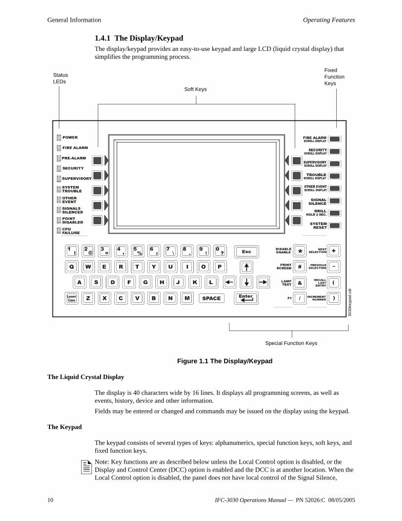
1.4.1 The Display/Keypad The display/keypad provides an easy-to-use keypad and large LCD (liquid crystal display) that simplifies the programming process.
Figure 1.1 The Display/Keypad
The Liquid Crystal Display
The display is 40 characters wide by 16 lines. It displays all programming screens, as well as events, history, device and other information.Fields may be entered or changed and commands may be issued on the display using the keypad.
The Keypad
The keypad consists of several types of keys: alphanumerics, special function keys, soft keys, and fixed function keys.
Note: Key functions are as described below unless the Local Control option is disabled, or the Display and Control Center (DCC) option is enabled and the DCC is at another location. When the Local Control option is disabled, the panel does not have local control of the Signal Silence,
Fixed Function Keys
Soft Keys
Status LEDs
Special Function Keys30
30ke
ypad
.cdr
10 IFC-3030 Operations Manual — PN 52026:C 08/05/2005
Operating Features General Information
System Reset, and Drill Fixed Function keys, or the SIGNAL SILENCE, SYSTEM RESET, and ACKNOWLEDGE soft keys. These functions must be performed by a remote device preprogrammed for this purpose. When this panel is not the DCC on a network, permission must be granted from the DCC before Signal Silence, System Reset, Acknowledge or Drill can be performed at this panel. Pressing one of these keys will automatically send a permission request to the DCC.
KeypadThe alphanumeric portion of the keypad is in standard QWERTY format. This keypad is functional mainly when an entry is requested by the system. Otherwise, pressing the keys results in no entry.
Soft KeysThe ten keys to the right and left of the display function to select commands that appear on the display. Each screen has different information, and each key changes function to suit the screen. Beneath each screen in this manual is a description of the function of each soft key.
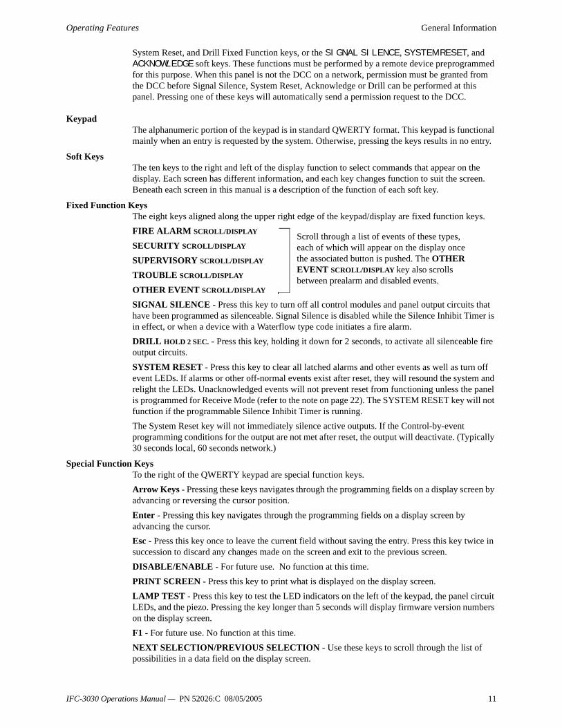
Fixed Function KeysThe eight keys aligned along the upper right edge of the keypad/display are fixed function keys.FIRE ALARM SCROLL/DISPLAY
SECURITY SCROLL/DISPLAY SUPERVISORY SCROLL/DISPLAY TROUBLE SCROLL/DISPLAY
OTHER EVENT SCROLL/DISPLAY SIGNAL SILENCE - Press this key to turn off all control modules and panel output circuits that have been programmed as silenceable. Signal Silence is disabled while the Silence Inhibit Timer is in effect, or when a device with a Waterflow type code initiates a fire alarm.DRILL HOLD 2 SEC. - Press this key, holding it down for 2 seconds, to activate all silenceable fire output circuits.SYSTEM RESET - Press this key to clear all latched alarms and other events as well as turn off event LEDs. If alarms or other off-normal events exist after reset, they will resound the system and relight the LEDs. Unacknowledged events will not prevent reset from functioning unless the panel is programmed for Receive Mode (refer to the note on page 22). The SYSTEM RESET key will not function if the programmable Silence Inhibit Timer is running.The System Reset key will not immediately silence active outputs. If the Control-by-event programming conditions for the output are not met after reset, the output will deactivate. (Typically 30 seconds local, 60 seconds network.)
Special Function KeysTo the right of the QWERTY keypad are special function keys. Arrow Keys - Pressing these keys navigates through the programming fields on a display screen by advancing or reversing the cursor position.Enter - Pressing this key navigates through the programming fields on a display screen by advancing the cursor.Esc - Press this key once to leave the current field without saving the entry. Press this key twice in succession to discard any changes made on the screen and exit to the previous screen.DISABLE/ENABLE - For future use. No function at this time.PRINT SCREEN - Press this key to print what is displayed on the display screen.LAMP TEST - Press this key to test the LED indicators on the left of the keypad, the panel circuit LEDs, and the piezo. Pressing the key longer than 5 seconds will display firmware version numbers on the display screen.F1 - For future use. No function at this time.NEXT SELECTION/PREVIOUS SELECTION - Use these keys to scroll through the list of possibilities in a data field on the display screen.
Scroll through a list of events of these types, each of which will appear on the display once the associated button is pushed. The OTHER EVENT SCROLL/DISPLAY key also scrolls between prealarm and disabled events.
IFC-3030 Operations Manual — PN 52026:C 08/05/2005 11
General Information Message Formats
RECALL LAST ENTRY -For future use. No function at this time. INCREMENT NUMBER - For future use. No function at this time.
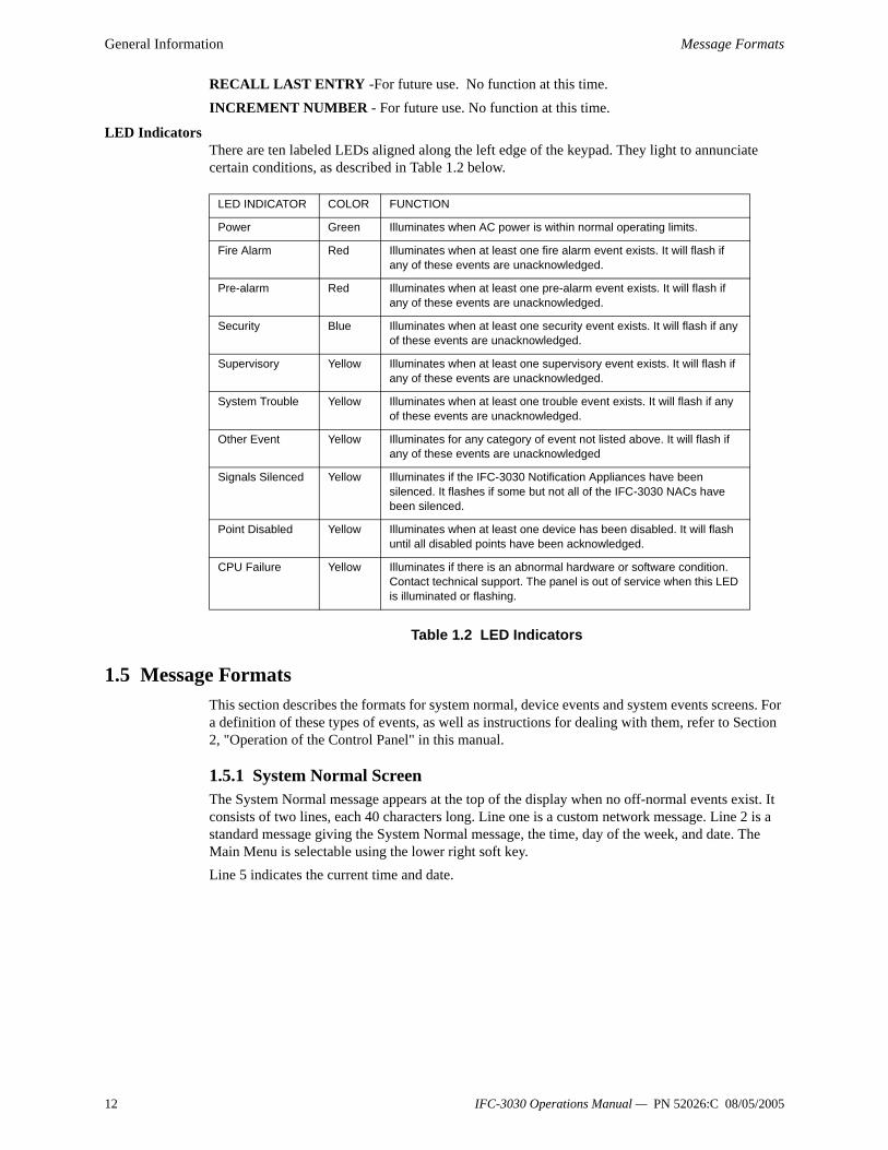
LED IndicatorsThere are ten labeled LEDs aligned along the left edge of the keypad. They light to annunciate certain conditions, as described in Table 1.2 below.
Table 1.2 LED Indicators
1.5 Message FormatsThis section describes the formats for system normal, device events and system events screens. For a definition of these types of events, as well as instructions for dealing with them, refer to Section 2, "Operation of the Control Panel" in this manual.
1.5.1 System Normal ScreenThe System Normal message appears at the top of the display when no off-normal events exist. It consists of two lines, each 40 characters long. Line one is a custom network message. Line 2 is a standard message giving the System Normal message, the time, day of the week, and date. The Main Menu is selectable using the lower right soft key.Line 5 indicates the current time and date.
LED INDICATOR COLOR FUNCTION
Power Green Illuminates when AC power is within normal operating limits.
Fire Alarm Red Illuminates when at least one fire alarm event exists. It will flash if any of these events are unacknowledged.
Pre-alarm Red Illuminates when at least one pre-alarm event exists. It will flash if any of these events are unacknowledged.
Security Blue Illuminates when at least one security event exists. It will flash if any of these events are unacknowledged.
Supervisory Yellow Illuminates when at least one supervisory event exists. It will flash if any of these events are unacknowledged.
System Trouble Yellow Illuminates when at least one trouble event exists. It will flash if any of these events are unacknowledged.
Other Event Yellow Illuminates for any category of event not listed above. It will flash if any of these events are unacknowledged
Signals Silenced Yellow Illuminates if the IFC-3030 Notification Appliances have been silenced. It flashes if some but not all of the IFC-3030 NACs have been silenced.
Point Disabled Yellow Illuminates when at least one device has been disabled. It will flash until all disabled points have been acknowledged.
CPU Failure Yellow Illuminates if there is an abnormal hardware or software condition. Contact technical support. The panel is out of service when this LED is illuminated or flashing.
12 IFC-3030 Operations Manual — PN 52026:C 08/05/2005
Message Formats General Information
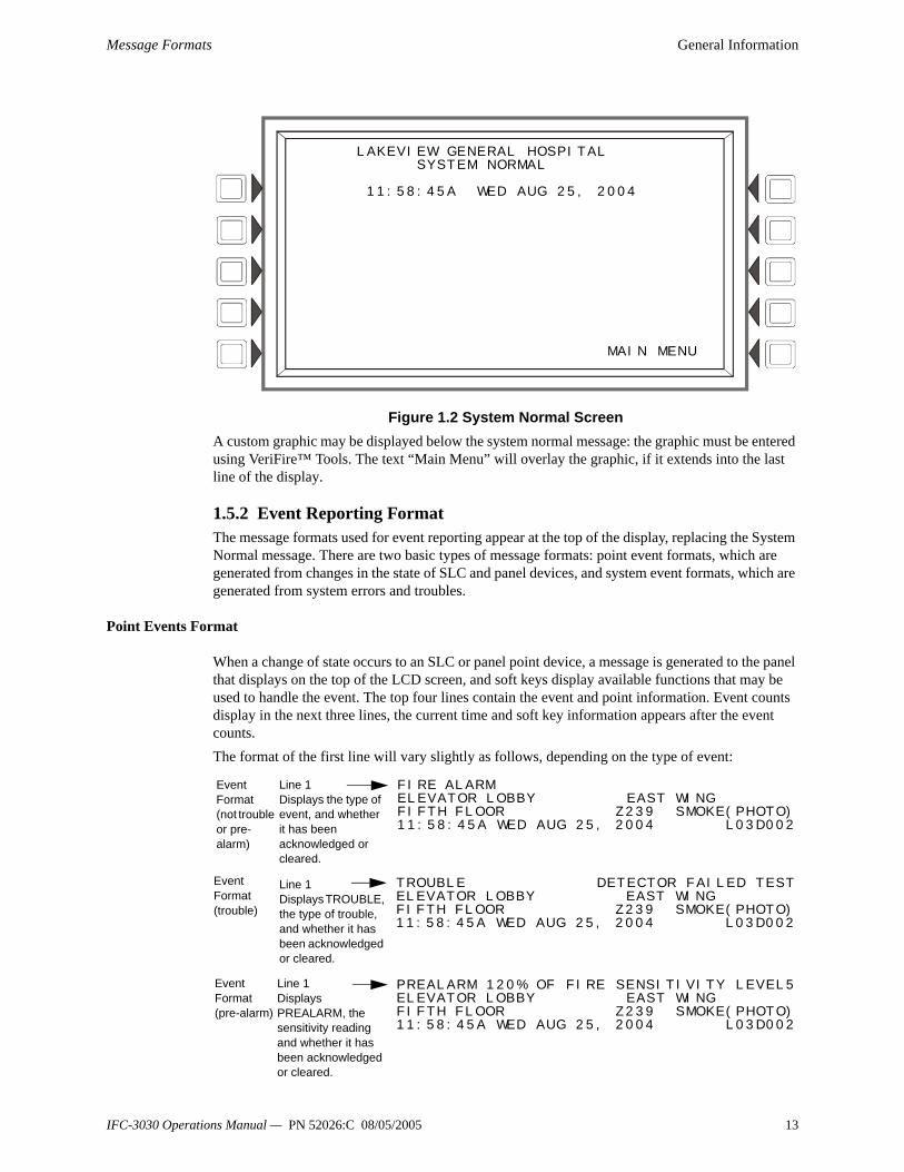
Figure 1.2 System Normal ScreenA custom graphic may be displayed below the system normal message: the graphic must be entered using VeriFire™ Tools. The text “Main Menu” will overlay the graphic, if it extends into the last line of the display.
1.5.2 Event Reporting FormatThe message formats used for event reporting appear at the top of the display, replacing the System Normal message. There are two basic types of message formats: point event formats, which are generated from changes in the state of SLC and panel devices, and system event formats, which are generated from system errors and troubles.
Point Events Format
When a change of state occurs to an SLC or panel point device, a message is generated to the panel that displays on the top of the LCD screen, and soft keys display available functions that may be used to handle the event. The top four lines contain the event and point information. Event counts display in the next three lines, the current time and soft key information appears after the event counts.The format of the first line will vary slightly as follows, depending on the type of event:
LAKEVIEW GENERAL HOSPITAL SYSTEM NORMAL 11:58:45A WED AUG 25, 2004 MAIN MENU
FIRE ALARMELEVATOR LOBBY EAST WINGFIFTH FLOOR Z239 SMOKE(PHOTO)11:58:45A WED AUG 25, 2004 L03D002
Line 1Displays the type of event, and whether it has been acknowledged or cleared.
TROUBLE DETECTOR FAILED TESTELEVATOR LOBBY EAST WINGFIFTH FLOOR Z239 SMOKE(PHOTO)11:58:45A WED AUG 25, 2004 L03D002
Line 1Displays TROUBLE, the type of trouble, and whether it has been acknowledged or cleared.
Event Format (not trouble or pre-alarm)
Event Format (trouble)
Line 1Displays PREALARM, the sensitivity reading and whether it has been acknowledged or cleared.
PREALARM 120% OF FIRE SENSITIVITY LEVEL5ELEVATOR LOBBY EAST WINGFIFTH FLOOR Z239 SMOKE(PHOTO)11:58:45A WED AUG 25, 2004 L03D002
Event Format (pre-alarm)
IFC-3030 Operations Manual — PN 52026:C 08/05/2005 13
General Information Message Formats
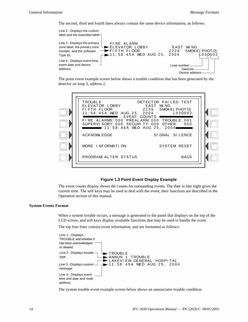
The second, third and fourth lines always contain the same device information, as follows:
The point event example screen below shows a trouble condition that has been generated by the detector on loop 3, address 2.
Figure 1.3 Point Event Display ExampleThe event counts display shows the counts for outstanding events. The date in line eight gives the current time. The soft keys may be used to deal with the event; their functions are described in the Operation section of this manual.
System Events Format
When a system trouble occurs, a message is generated to the panel that displays on the top of the LCD screen, and soft keys display available functions that may be used to handle the event.The top four lines contain event information, and are formatted as follows:
The system trouble event example screen below shows an annunciator trouble condition.
FIRE ALARM ELEVATOR LOBBY EAST WING FIFTH FLOOR Z239 SMOKE(PHOTO)11:58:45A WED AUG 25, 2004 L03D002
Line 2 - Displays the custom label and the extended label
Line 3 - Displays the primary zone label, the primary zone number, and the software Type ID.
Line 4 - Displays event time, event date and device address.
Loop numberDetector
Device address
TROUBLE DETECTOR FAILED TESTELEVATOR LOBBY EAST WING FIFTH FLOOR Z239 SMOKE(PHOTO)11:58:45A WED AUG 25, 2004 L03D002 EVENT COUNTS FIRE ALARMS:000 PREALARM:000 TROUBLE:001SUPERVISORY:000 SECURITY:000 OTHER: 000 11:58:46A WED AUG 25, 2004 ACKNOWLEDGE SIGNAL SILENCE MORE INFORMATION SYSTEM RESET PROGRAM/ALTER STATUS BACK
TROUBLE ANNUN 1 TROUBLE LAKEVIEW GENERAL HOSPITAL 11:58:45A WED AUG 25, 2004
Line 1 - Displays TROUBLE and whether it has been acknowledged or cleared
Line 2 - Displays trouble type
Line 3 - Displays custom message.
Line 4 - Displays event time and date and node address.
14 IFC-3030 Operations Manual — PN 52026:C 08/05/2005

Navigating Menu and Programming Screens General Information
Figure 1.4 System Event Display ExampleThe event counts display shows the counts for outstanding events. The date in line eight gives the current time. The soft keys may be used to deal with the event; their functions are described in the Operation section of this manual.
1.6 Navigating Menu and Programming ScreensThe Main Menu (refer to Figure 1.5) leads to screens with various menu options. Choices may be made from the menu screens by pressing the soft key closest to the menu option.Field information may be added/modified using the keypad and special function keys.Arrow keys on the keypad can be used to navigate between fields on a screen if there are no soft keys to select the fields.Pressing a BACK soft key on a screen returns the programmer to the previous screen without saving the information entered.Pressing an ACCEPT soft key will save information entered on the screen. It may also return to the previous screen and/or perform other functions as described in the soft key section for each screen.When the panel can not read a specified point (that is, if the point entered on the screen for processing does not exist in the panel’s programming) it will display an error screen for several seconds, then return to the screen where the address was entered. The user must check his input and investigate the state of the point.
1.7 The Main MenuThe Main Menu screen is the means by which the programmer can access displays, history information, printing and programming menus. This screen is accessible from the System Normal Screen (Refer to Figure 1.2), and from most other screens by pressing the BACK soft key until it displays.
TROUBLE ANNUN 1 TROUBLE LAKEVIEW GENERAL HOSPITAL 11:58:45A WED AUG 25, 2004 EVENT COUNTS FIRE ALARMS:000 PREALARM:000 TROUBLE:001SUPERVISORY:000 SECURITY:000 OTHER: 000 11:58:46A WED JAUG 25, 2004 ACKNOWLEDGE SIGNAL SILENCE MORE INFORMATION SYSTEM RESET PROGRAM/ALTER STATUS BACK
IFC-3030 Operations Manual — PN 52026:C 08/05/2005 15

General Information The Main Menu
Figure 1.5 Main Menu ScreenSoft KeysPressing the soft keys brings the user to the screens described below.
1.7.1 Event Counts DisplayPressing the soft key to the left of the Event Counts Display message on the Main Menu brings up the Event Counts screen. This screen will automatically display if an off-normal event requiring acknowledgement occurs, unless the panel is in programming mode. Fire alarm events will display even in programming mode.Lines six and seven display current counts of off-normal events in six categories. The counts include both acknowledged and unacknowledged events.
Figure 1.6 Events Count Display ScreenSoft KeysACKNOWLEDGE FIRE ALARM - Press this key to acknowledge an event. The command will read ACKNOWLEDGE FIRE ALARM if the event is a fire alarm. It will read ACKNOWLEDGE if the event is any other type. The command will not display if there are no events to acknowledge.MORE INFORMATION - Press this key to go to the MORE INFORMATION screen, described in Section 1.7.2 below. This button will not display if no off-normal events exist.
LAKEVIEW GENERAL HOSPITAL SYSTEM NORMAL 11:58:45A WED AUG 25, 2004 EVENT COUNTS DISPLAY READ STATUS PROGRAM/ALTER STATUS MULTIPLE EVENT LIST PRINTER FUNCTIONS HISTORY DISPLAY BACK
FIRE ALARMELEVATOR LOBBY EAST WINGFIFTH FLOOR Z005 SMOKE(PHOTO)11:57:45A WED AUG 25, 2004 L03D052
EVENT COUNTSFIRE ALARMS:001 PREALARM:000 TROUBLE:000SUPERVISORY:000 SECURITY:000 DISABLE:000
11:58:45A WED AUG 25, 2004
ACKNOWLEDGE FIRE ALARM SIGNAL SILENCE
MORE INFORMATION SYSTEM RESET
PROGRAM/ALTER STATUS BACK
16 IFC-3030 Operations Manual — PN 52026:C 08/05/2005

The Main Menu General Information
PROGRAM/ALTER STATUS - Press this key to go to the PROGRAM/ALTER STATUS screen, which also can be reached from the main menu. This screen will require a password. For programming instructions, refer to the IFC-3030 Programming Manual.SIGNAL SILENCE - Press this key to silence all IFC-3030 outputs programmed as silenceable.SYSTEM RESET - Press this key to reset the system.
1.7.2 More InformationPressing the More Information soft key displays a screen that contains additional information about the event shown in the top four lines.
Figure 1.7 More Information ScreenDisplayLines 1 through 4 - Event informationLine 5 - Screen titleLines 6 through 9 - The Custom Action Message programmed for the point in alarmLine 10 - blank
Line 11 and 14 - These lines exist only for smoke/heat detectors. They do not display for wireless smoke detectors.
Line 11 VALUES :The screen displays the Alarm and Prealarm values that are in effect when more information is requested. For example, if occupied settings are in effect, occupied values will display.121% OF ALARM - This field gives the detector reading as it relates to its preprogrammed alarm level value (indicated in the next line on the screen). The example above shows the detector exceeding the alarm level by 21%.Note: For Beam detectors in CLIP mode, the alarm value will always equal zero (0)% when it is not in alarm or 100% when it is in alarm. 145% OF PREALARM - This field gives the detector reading as it relates to its preprogrammed prealarm level value (indicated in the next line on the screen). The example above shows the detector exceeding the prealarm level by 45%.
Line 12The screen displays the Alarm and Prealarm levels that are in effect when more information is requested. For example, if unoccupied settings are in effect, they will display.ALARM: 6=1.66% - Six is the preprogrammed alarm level value for this detector: its value is 1.66%, indicating the percent per foot obscuration value assigned to level 6.PREALARM: 3=0.47% - Three is the preprogrammed alarm level value for this detector: its value is 0.47%, indicating the percent per foot obscuration value assigned to level 3.
Line 13
ACKNOWLEDGED FIRE ALARMELEVATOR LOBBY EAST WINGFIFTH FLOOR Z005 SMOKE(PHOTO)11:58:45A WED AUG 25, 2004 L03D052
INFORMATION/ACTIONCALL 203-555-1212GO TO ALARM SITE AND INVESTIGATEAPPROACH THE ALARM LOCATION WITH CAUTIONBRING CELL PHONE AND REPORT WHEN ON SITE
VALUES: 121% OF ALARM, 145% OF PREALARMALARM: 6= 1.66%, PREALARM; 3= 0.47%ACTION/STATUS: NONE/VERY CLEANPEAKS:56% VERIFY COUNT:02 CO-OP:D100,158
12:22:34P WED AUG 25, 2004BACK
IFC-3030 Operations Manual — PN 52026:C 08/05/2005 17

General Information The Main Menu
ACTION/STATUS: NONE/VERY CLEAN - This displays the maintenance status of the device. The message that appears in this field depends on the drift compensation value. A detector will automatically compensate for environmental contaminants and other factors over time, until the tolerance value has been exceeded. The FACP will signal a trouble condition when this level has been reached. Refer to the following table for messages and required action.
Line 13 does not display for Acclimate detectors.Line 14
PEAKS: 56% - This value represents the highest percent per foot obscuration reading taken by this detector. It can be a historical figure, and does not necessarily represent the highest reading for this particular alarm. Re-initializing the detector would reset this value to zero. VERIFY COUNT: 02 - This displays the number of times the detector has gone into alarm. This count aids in differentiating false alarms from actual alarms by showing repeated alarm events that have come into the device. In this example, the detector has gone into alarm two times since the verification count was begun. The FACP will signal a trouble condition when the verify count is exceeded.CO-OP: D100,158 - Indicates the address(es) of any detector(s) linked with the detector that’s in alarm for Co-operative Multi-alarm Sensing. This field does not display for Acclimate detectors, Beam detectors or Heat detectors.
Line 15 - The current time and date are displayed in this line.Line 16
BACK - Press to return to the previous screen.
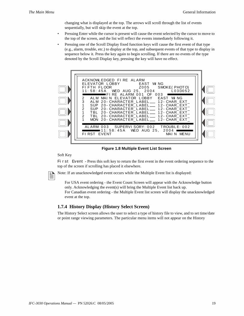
1.7.3 Multiple Event ListPressing the Multiple Event List soft key shows off-normal events simultaneously in groups of eight. One event is shown at the top, and seven are shown in the list below it. The list will consist of the events immediately following the event at the top, with the priority of event types determined by the programmed Event Ordering setting (USA or Canada).
• Using the Next Selection/Previous Selection special function keys to scroll through the list will replace the event at the top of the screen with the first event in the series displayed below it.
• Using the Up/Down arrow keys to scroll through the list will not replace the event at the top of the screen: pressing the arrow keys will scroll a cursor through the seven events below without
Message DescriptionReplace/Malfunction Replace the defective detector. The detector may not
operate properly.None/Very Clean No action necessary. The detector readings are near ideal.None/Clean No action necessary. Although not ideal, the detector will
activate at the selected sensitivity level.None/Fairly Clean No action necessary. The detector will activate at the
selected sensitivity level.Needs Cleaning Clean the detector soon. The detector may cause a false
alarm because it has reached the drift compensation tolerance value.
Needs Immediate Cleaning Clean immediately! The detector is a false alarm risk. The drift compensation tolerance value has been exceeded.
USA Event Order Canada Event OrderFire FireSecurity SupervisorySupervisory TroubleTrouble PrealarmPrealarm DisabledDisabled
18 IFC-3030 Operations Manual — PN 52026:C 08/05/2005
The Main Menu General Information
changing what is displayed at the top. The arrows will scroll through the list of events sequentially, but will skip the event at the top.
• Pressing Enter while the cursor is present will cause the event selected by the cursor to move to the top of the screen, and the list will reflect the events immediately following it.
• Pressing one of the Scroll Display fixed function keys will cause the first event of that type (e.g., alarm, trouble, etc.) to display at the top, and subsequent events of that type to display in sequence below it. Press the key again to begin scrolling. If there are no events of the type denoted by the Scroll Display key, pressing the key will have no effect.
Figure 1.8 Multiple Event List ScreenSoft KeyFirst Event - Press this soft key to return the first event in the event ordering sequence to the top of the screen if scrolling has placed it elsewhere.
Note: If an unacknowledged event occurs while the Multiple Event list is displayed:
For USA event ordering - the Event Count Screen will appear with the Acknowledge button only. Acknowledging the event(s) will bring the Multiple Event list back up.For Canadian event ordering - the Multiple Event list screen will display the unacknowledged event at the top.
1.7.4 History Display (History Select Screen)The History Select screen allows the user to select a type of history file to view, and to set time/date or point range viewing parameters. The particular menu items will not appear on the History
ACKNOWLEDGED FIRE ALARM ELEVATOR LOBBY EAST WING FIFTH FLOOR Z005 SMOKE(PHOTO)11:58:45A WED AUG 25, 2004 L03D052 FIRE ALARM:001 OF 003 2 ALM MAIN ELEVATOR LOBBY EAST WING 3 ALM 20-CHARACTER_LABEL 12-CHAR_EXT_1 SUP 20-CHARACTER_LABEL 12-CHAR_EXT_2 SUP 20-CHARACTER_LABEL 12-CHAR_EXT_1 TBL 20-CHARACTER_LABEL 12-CHAR_EXT_2 TBL 20-CHARACTER_LABEL 12-CHAR_EXT_1 MON 20-CHARACTER_LABEL 12-CHAR_EXT_ ALARM:003 SUPERVISORY:002 TROUBLE:002 11:58:45A WED AUG 25, 2004FIRST EVENT MAIN MENU
IFC-3030 Operations Manual — PN 52026:C 08/05/2005 19

General Information The Main Menu
Display screen if no associated events are in the queue.
Figure 1.9 History Display Select ScreenSoft KeysALL EVENTS, ALARMS ONLY, TROUBLES ONLY, SUPERVISORY ONLY, AND SECURITY/OTHERS - Pushing the associated soft key selects the type of history to be viewed. TIME/DATE INTERVAL - Sets a time/date interval of events to be displayed.POINT RANGE - Sets a range of points for which events will be displayed.Refer to the section "Viewing and Printing History Information" on page 51 for a full description of History Select.
1.7.5 Read StatusPressing the Read Status soft key brings up screens to view the present status of points, zones, and other system information. Refer to the section "Read Status" on page 41 for a full description of Read Status.
1.7.6 Program/Alter StatusPressing the Program/Alter Status soft key brings up screens for panel programming, point programming, autoprogramming, clear programming, altering the status of points, walk test, and other information. A password is required. Refer to this panel’s programming manual for information on these functions.
1.7.7 Printer Functions Pressing the Printer Functions soft key brings up screens to print reports. Refer to the section "Printing Reports" on page 55 for descriptions and illustrations. This key will appear only if a printer has been selected through programming. Refer to this panel’s programmming manual for information on printer selection.
LAKEVIEW GENERAL HOSPITAL SYSTEM NORMAL 11:58:45A WED AUG 25, 2004 N124 HISTORY SELECT ALL EVENTS SECURITY/OTHERS ALARMS ONLY TIME/DATE INTERVAL TROUBLES ONLY POINT RANGE SUPERVISORY ONLY BACK
20 IFC-3030 Operations Manual — PN 52026:C 08/05/2005

Overview Operation of the Control Panel
Section 2 Operation of the Control Panel
2.1 OverviewThe control panel periodically checks for events. An event can be any change in the status of a device, a transfer of information between a device and the FACP, or a transfer of information between two devices. Some events are considered background events and are not seen by the user. The events that are of primary concern to the operator are those identified as off-normal events. An off-normal event is an event which indicates activity or change in condition that requires the attention and/or response of an operator. Examples of possible off-normal events are:• Activation or change in condition of a monitoring device such as a detector or module• System troubles, such as battery problems, device supervision problems, etc.When there are no off-normal events, the panel displays the System Normal screen (refer to Figure 2.1). When there is an off-normal event, the panel will display it (for event formats, refer to "Event Reporting Format" on page 13 ). The action required will vary according to the type of event.
2.1.1 System NormalThe system operates in System Normal mode when no alarms or troubles exist. In this mode, the control panel displays a System Normal message as follows
Figure 2.1 System Normal ScreenThe control panel performs the following functions at regular intervals:• Polls all SLC devices and Panel Circuits to check for valid replies, alarms, troubles, circuit
integrity, and supervisory signals, etc.• Checks power supply troubles and batteries• Refreshes the panel display and updates time• Scans for any panel screen, keypad, and Control Key entries• Performs a detector automatic test operation• Tests system memory• Monitors for microcontroller failureNo action is required of the operator when the panel is operating in Normal mode.
2.1.2 Acknowledging an EventWhen the panel detects an off-normal event and the information is displayed on-screen, one of the
LAKEVIEW GENERAL HOSPITAL SYSTEM NORMAL 11:58:45A WED AUG 25, 2004 MAIN MENU
IFC-3030 Operations Manual — PN 52026:C 08/05/2005 21

Operation of the Control Panel Overview
soft keys displayed on the screen is ACKNOWLEDGE. Use this key to respond to new alarm or trouble signals. When this key is pressed, the control panel does the following:• It silences the piezo sounder on the panel if it is enabled• It transfers the event to the history buffer• If the panel is networked, it will send a network message.There are two types of acknowledge; point and block. Point acknowledge is for fire alarms: fire alarms are acknowledged one at a time when the Acknowledge soft key is pressed. Block acknowledge is for all other types of off-normal events: these events are acknowledged all at the same time, with a single stroke to the Acknowledge soft key.
Note: If Local Control is disabled, acknowledgements can not be made by pressing the ACKNOWLEDGE soft key on the panel display. Events must be acknowledged from a preprogrammed remote location. When DCC (Display and Control Center) participation is enabled, panel acknowledgement can be performed when it is the DCC. When it is not, permission must be granted from the DCC before the panel can make an acknowledgement. Pressing the ACKNOWLEDGE soft key will automatically request permission from the DCC.
Note: If the panel is programmed for Receive Mode, events and the clearing of events must be handled one at a time: each event must be acknowledged, and each clear (whether the clear occurs automatically or as the result of a panel reset) must be acknowledged.
22 IFC-3030 Operations Manual — PN 52026:C 08/05/2005

Fire Alarm Event Operation of the Control Panel
2.2 Fire Alarm Event
2.2.1 How the Control Panel Indicates a Fire AlarmWhen an initiating device (detector or monitor module) activates, the control panel does the following:• Produces a steady audible tone (if the piezo is enabled)• Activates the System Alarm relay (TB4). It will also activate the Security (TB1) and
Supervisory (TB2) relays if their switches have been configured for alarm• Flashes the FIRE ALARM LED• Displays FIRE ALARM in the upper left corner of the display, a Type Code that indicates the type
of device that activated the fire alarm, and other information specific to the device. The message occupies the top four lines of the screen, replacing the System Normal message as shown in Figure 2.2 below. Refer to “Point Events Format” on page 13 for a full description of each message field
• Sends an Alarm message to the History buffer and installed printer and annunciators• Latches the control panel in alarm. (You cannot return the control panel to normal operation
until you correct the alarm condition and reset the control panel)• Initiates any Control-By-Event actions• Starts timers (such as Silence Inhibit, Auto Silence)• Activates the general alarm zone (Z000)
Note: If a monitor module programmed with a WATERFLOW Type Code initiates a fire alarm, the control panel disables the SIGNAL SILENCE key and the Auto Silence Timer.
Figure 2.2 Fire Alarm Message Display Example
2.2.2 How to Respond to a Fire AlarmIf the control panel indicates a fire alarm, the operator can do the following:• To silence the panel sounder:
Press the ACKNOWLEDGE soft key. The local sounder will silence and the FIRE ALARM LED will change from flashing to steady. The control panel will send an acknowledge message to the panel display, history buffer, installed printers and annunciators.
• To silence any activated outputs that are programmed as silenceable:Press the SIGNAL SILENCE soft key. SIGNALS SILENCED LED light steady. The control panel sends a Signal Silenced message to the History buffer, installed printers and annunciators.
FIRE ALARM ELEVATOR LOBBY EAST WING FIFTH FLOOR Z005 SMOKE(PHOTO)11:58:45A WED AUG 25, 2004 L03D052 EVENT COUNTS FIRE ALARMS:001 PREALARM:000 TROUBLE:000SUPERVISORY:000 SECURITY:000 OTHER: 000 11:59:35A WED AUG 25, 2004 ACKNOWLEDGE SIGNAL SILENCE MORE INFORMATION SYSTEM RESET PROGRAM/ALTER STATUS MAIN MENU
IFC-3030 Operations Manual — PN 52026:C 08/05/2005 23
Operation of the Control Panel Fire Alarm Event
1. Check the Alarm message for its location and type. Press the MORE INFORMATION soft key to display the MORE INFORMATION screen and view additional information on the device and possibly preprogrammed text for recommended action. ( Refer to Figure 1.7 on page 17 for an example of the this screen and an explanation of its fields.)
2. Correct the condition causing the alarm.3. When the alarm condition is corrected, press the SYSTEM RESET soft key to return the control
panel to normal operation (indicated by the “System Normal” message). The control panel sends a “System Normal” message to the panel display, History buffer and installed printer.
The soft key PROGRAM/ALTER STATUS is also displayed on this screen. A password is required to enter these menus, which are described in the IFC-3030 Programming manual.
2.2.3 Interpreting Type ID CodesThe Type ID code that displays in the fire alarm message is related to the type and function of the point that initiates the fire alarm. For example, a monitor module with a PULL STATION Type ID code means that the monitor module connects to a manual pull station. If the Type ID code is unfamiliar, refer to "Software Type ID Codes" on page 63. This appendix is an alphabetical list of Type ID codes with an explanation of each.
24 IFC-3030 Operations Manual — PN 52026:C 08/05/2005

System or Point Trouble Event Operation of the Control Panel
2.3 System or Point Trouble Event
2.3.1 How the Control Panel Indicates a System or Point TroubleA system or point trouble occurs when the control panel detects an electrical or mechanical fault. The panel will react differently depending on whether or not there are higher priority unacknowledged events.When no higher priority unacknowledged events are exist, the control panel:• Produces a pulsed audible tone (if the piezo is enabled)• Activates the Trouble relay (TB3)• Flashes the SYSTEM TROUBLE LED• Displays a Type Code that indicates the type of device with a trouble (if a point trouble)• Displays TROUBLE in the upper left corner of the panel display and, if a point trouble, the
type of trouble and information specific to the device. (A system and a point trouble message are shown in the figures below)
• Sends a Trouble message to the history buffer, installed printer and annunciatorsWhen an unacknowledged event with a higher priority exists, the control panel retains the indications of the higher priority event (the message, lit LED, audible tone, etc.) while activating the Trouble relay, flashing the SYSTEM TROUBLE LED, and sending a Trouble message to the history buffer, installed printer and annunciators.A system trouble message is shown in Figure 2.3, and a point trouble is shown in Figure 2.4. Refer to “Event Reporting Format” on page 13 for identification of each message field.
Figure 2.3 Sample Message for System Trouble
TROUBLE ANNUN 1 TROUBLE 11:58:45A WED AUG 25, 2004 EVENT COUNTS FIRE ALARMS:000 PREALARM:000 TROUBLE:001SUPERVISORY:000 SECURITY:000 DISABLE:000 11:59:35A WED AUG 25, 2004 ACKNOWLEDGE SIGNAL SILENCE SYSTEM RESET PROGRAM/ALTER STATUS MAIN MENU
IFC-3030 Operations Manual — PN 52026:C 08/05/2005 25

Operation of the Control Panel System or Point Trouble Event
Figure 2.4 Sample Message for Point Trouble
2.3.2 How to Respond to a System or Point TroubleIf the control panel indicates a trouble, the operator can do the following:
1. Press the ACKNOWLEDGE soft key to silence the panel sounder and switch the SYSTEM TROUBLE LED from flashing to steady—regardless of the number of troubles, alarms, security and supervisory signals.The control panel sends an acknowledge message to the History buffer, installed printers and annunciators.
2. Check the trouble message for an indication of the trouble.• Refer to Table 2.1 or Table 2.2 below for point and system trouble explanations, if necessary.• Press the MORE INFORMATION soft key to display the MORE INFORMATION screen and
view additional information on the device and possibly preprogrammed text for recommended action. ( Refer to Figure 1.7 on page 17 for an example of the this screen and an explanation of its fields.)
3. Correct the condition causing the trouble. If the trouble clears, the control panel sends a Clear Trouble message to the History buffer, installed printers and annunciators.
If all troubles clear and no supervisory signals or fire alarms exist, the control panel does the following:• Returns to Normal operation (indicated by the “System Normal” message)• Sends a “System Normal” message to the panel display, History buffer, installed printers and
annunciators• Restores troubles automatically - even if troubles are not acknowledgedThe soft key PROGRAM/ALTER STATUS is also displayed on this screen. A password is required to enter these menus, which are described in this panel’s programming manual.
2.3.3 Trouble TypesThere are a variety of point or system trouble types that may appear in the trouble message. The tables below give lists of the troubles and indications of their cause.
Point (Device) Troubles
A message from the “Trouble Type” column in Table 2.1 will appear in the upper right corner of the panel display when a point (device) trouble occurs. Use this table to help determine what the trouble is.
TROUBLE DETECTOR FAILED TESTELEVATOR LOBBY EAST WING FIFTH FLOOR SMOKE(PHOTO)11:58:45A WED AUG 25, 2004 L01D136 EVENT COUNTS FIRE ALARMS:000 PREALARM:000 TROUBLE:001SUPERVISORY:000 SECURITY:000 DISABLE:000 11:59:35A WED AUG 25, 2004 ACKNOWLEDGE SIGNAL SILENCE MORE INFORMATION SYSTEM RESET PROGRAM/ALTER STATUS MAIN MENU
26 IFC-3030 Operations Manual — PN 52026:C 08/05/2005

System or Point Trouble Event Operation of the Control Panel
POINT TROUBLESTROUBLE TYPE TROUBLE DESCRIPTION ACTIONAC FAILURE The main or auxiliary power supply has lost AC
power.Determine whether there is an AC power loss or whether the power supply and wiring is correct.
ALIGNMENT MODE A beam detector is in configuration mode. No action is necessary, as the trouble will clear when the configuration is complete. However, the detector will not detect a fire while this trouble exists.
BATTERY HIGH The power supply’s battery charge is too high. Check the batteries for problems. Replace batteries if necessary.
BATTERY LOW The power supply’s battery charge is low, or the RFX device’s battery charge is low.
Check the batteries for problems. Replace batteries if necessary.
BEAM BLOCKED Something has come between the detector’s beam and its reflector.
Investigate and clear the blockage.
BRAND MISMATCH The brand of this SLC device is incompatible with this FACP system.
Replace with compatible device.
CHARGER FAULT The power supply’s battery charger is not working properly.
Correct the fault.
DET FAILED TEST This detector has failed the FACP’s periodic detector test for alarm capabilities.
The detector should be removed and replaced by an authorized service representative.
DUAL ADDRESS There is more than one device of a single type (detector or module) with the same SLC address. A detector and a module can share the same address on an SLC, but two detectors, or two modules, can not. Note that some addressable devices (e.g. certain power supplies, XPIQs and RFXs) may not appear to be detectors or modules, but are addressed on the SLC as such.
Readdress the incorrect device.
GENERAL TROUBLE
The power supply is not working properly. Check the battery for problems. Replace battery if necessary.
GROUND FAULT There is a ground fault on the main or auxiliary power supply.
Correct the fault.
INITIALIZATION MODE
A beam detector is running through its initialization sequence.
The detector will not detect a fire until the initialization process is complete and this trouble has cleared.
INVALID RESPONSE
The device has returned a response to the panel that the panel did not expect.
Check the device for functionality, addressing and wiring.
LOW TEMPERATURE
The temperature read by a Heat+ or Acclimate™+ detector is too low.
Raise the heat in the area of the detector.
LOW THRESHOLD The detector chamber reading is too low; the detector is not operating properly.
The detector must be removed and replaced by an authorized service representative.
MAINTENANCE REQ
The detector is dirty and needs cleaning Clean the detector.
MAINT URGENT The detector requires cleaning immediately. It is a false alarm risk.
Clean the detector immediately.
MISMAT HDWE TYPE
The programming information in the panel’s database for this device does not match the type of device at the address specified.
Correct programming.
MOD EXT PWR LOSS
The control module point has lost external power.
Determine whether there is a DC power loss.
NO ANSWER The device (module or detector) is not responding to the poll. Either the device is not working or it is not connected properly.
Determine whether the device is functional, and connected and addressed properly on the SLC.
NORMAL Indicates activated monitor module set to monitor trouble condition.
Correct trouble condition.
OPEN CIRCUIT The module device has an open circuit on its supervised wiring.
Check the connections from the module to the input or output device to which it is wired.
Table 2.1 Point (Device) Troubles (1 of 2)
IFC-3030 Operations Manual — PN 52026:C 08/05/2005 27

Operation of the Control Panel System or Point Trouble Event
System Troubles
A message from the “Trouble Type” column in Table 2.2 will appear in the second line on the left of the panel display when a device trouble occurs. Use this table to help determine the cause of the trouble.
RFX COMM LOSS Communication has been lost with an RFX device
Check the RFX to determine the problem.
SECURITY TAMPER An RFX device has been removed from its base. Check the RFX device for tampering.SHORT CIRCUIT The module device has a short circuit on its
supervised wiring.Check the connections from the module to the input or output device to which it is wired.
VERIFY OVER MAX This detector, or M302MJ or panel circuit monitor module, which has been programmed to participate in alarm verification, has gone into and come out of its programmed verification limit without going into alarm. Either something is wrong with the detector or there is a condition nearby (such as someone smoking) that causes it to go into verification frequently.
Check the detector and the conditions nearby to determine the problem.
POINT TROUBLESTROUBLE TYPE TROUBLE DESCRIPTION ACTION
Table 2.1 Point (Device) Troubles (2 of 2)
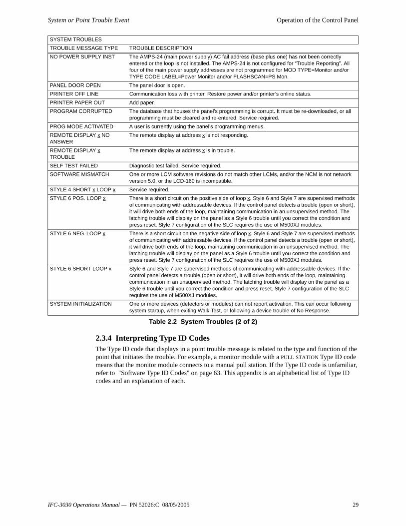
SYSTEM TROUBLESTROUBLE MESSAGE TYPE TROUBLE DESCRIPTIONADV WALK TEST There is an Advanced Walk Test in progress.ANNUN x NO ANSWER The annunciator at address x is not responding.ANNUN x TROUBLE The annunciator at address x is in trouble.AUXILIARY TROUBLE Auxiliary device connected to the IFC-3030 CPU at J5 is in trouble or cable is missing.BASIC WALK TEST A Basic Walk Test is in progress.CORRUPT LOGIC EQUAT The database that houses the panel’s logic equations is corrupt. It must be re-downloaded, or all
programming must be cleared and re-entered.DRILL INITIATED Drill has been initiated locally.DRILL RECEIVED Drill has been initiated remotely.EPROM ERROR The application and/or boot code is corrupt. Service required.EXTERNAL RAM ERROR The external RAM test failed. Service required.GROUND FAULT A ground fault has occurred within the panel.GROUND FAULT LOOP x There is a ground fault on loop x. INTERNAL RAM ERROR The internal RAM test failed. Service required.LOADING.NO SERVICE A program or database download is in progress. The panel is NOT providing fire protection during
the download. Proper authorities should be notified while a download is in progress so that other means of fire protection can be supplied.
LOOP x- x COMM FAILURE Loops x and x are not responding. The LCM and LEM for those loops must be serviced.MAN EVAC INITIATED Local initiation of DRILL.MAN EVAC RECEIVED Network initiation of DRILL.MANUAL MODE ENTERED An annunciator has been placed in manual mode.NCM COMM LOSS Communication is lost between the JCPU-3030 and the NCM.NETWORK FAIL PORT x Communication lost between NCM Port x and corresponding node.NETWORK INCOMPATIBILITY An incompatible product exists on this network.NFPA 24HR REMINDER This message occurs every day at 11 am if any troubles exist.NVRAM BATT TROUBLE Battery backup and/or clock backup is low. Replace battery.NO DEV. INST ON L1 No devices are installed on the system.
Table 2.2 System Troubles (1 of 2)
28 IFC-3030 Operations Manual — PN 52026:C 08/05/2005
System or Point Trouble Event Operation of the Control Panel
2.3.4 Interpreting Type ID CodesThe Type ID code that displays in a point trouble message is related to the type and function of the point that initiates the trouble. For example, a monitor module with a PULL STATION Type ID code means that the monitor module connects to a manual pull station. If the Type ID code is unfamiliar, refer to "Software Type ID Codes" on page 63. This appendix is an alphabetical list of Type ID codes and an explanation of each.
NO POWER SUPPLY INST The AMPS-24 (main power supply) AC fail address (base plus one) has not been correctly entered or the loop is not installed. The AMPS-24 is not configured for “Trouble Reporting”. All four of the main power supply addresses are not programmed for MOD TYPE=Monitor and/or TYPE CODE LABEL=Power Monitor and/or FLASHSCAN=PS Mon.
PANEL DOOR OPEN The panel door is open.PRINTER OFF LINE Communication loss with printer. Restore power and/or printer’s online status.PRINTER PAPER OUT Add paper.PROGRAM CORRUPTED The database that houses the panel’s programming is corrupt. It must be re-downloaded, or all
programming must be cleared and re-entered. Service required.PROG MODE ACTIVATED A user is currently using the panel’s programming menus.REMOTE DISPLAY x NO ANSWER
The remote display at address x is not responding.
REMOTE DISPLAY x TROUBLE
The remote display at address x is in trouble.
SELF TEST FAILED Diagnostic test failed. Service required.SOFTWARE MISMATCH One or more LCM software revisions do not match other LCMs, and/or the NCM is not network
version 5.0, or the LCD-160 is incompatible.STYLE 4 SHORT x LOOP x Service required.STYLE 6 POS. LOOP x There is a short circuit on the positive side of loop x. Style 6 and Style 7 are supervised methods
of communicating with addressable devices. If the control panel detects a trouble (open or short), it will drive both ends of the loop, maintaining communication in an unsupervised method. The latching trouble will display on the panel as a Style 6 trouble until you correct the condition and press reset. Style 7 configuration of the SLC requires the use of M500XJ modules.
STYLE 6 NEG. LOOP x There is a short circuit on the negative side of loop x. Style 6 and Style 7 are supervised methods of communicating with addressable devices. If the control panel detects a trouble (open or short), it will drive both ends of the loop, maintaining communication in an unsupervised method. The latching trouble will display on the panel as a Style 6 trouble until you correct the condition and press reset. Style 7 configuration of the SLC requires the use of M500XJ modules.
STYLE 6 SHORT LOOP x Style 6 and Style 7 are supervised methods of communicating with addressable devices. If the control panel detects a trouble (open or short), it will drive both ends of the loop, maintaining communication in an unsupervised method. The latching trouble will display on the panel as a Style 6 trouble until you correct the condition and press reset. Style 7 configuration of the SLC requires the use of M500XJ modules.
SYSTEM INITIALIZATION One or more devices (detectors or modules) can not report activation. This can occur following system startup, when exiting Walk Test, or following a device trouble of No Response.
SYSTEM TROUBLESTROUBLE MESSAGE TYPE TROUBLE DESCRIPTION
Table 2.2 System Troubles (2 of 2)
IFC-3030 Operations Manual — PN 52026:C 08/05/2005 29

Operation of the Control Panel Pre-alarm Event
2.4 Pre-alarm EventThe Pre-alarm function is used to receive an early warning of potential or incipient fire conditions. The Pre-alarm function provides one of two settings as follows:• Alert – a non-latching setting that causes a Pre-alarm when a detector reaches its programmed
Pre-alarm sensitivity threshold. Non-latching means the condition will automatically restore to normal once the detector’s sensitivity readings drop below its Pre-alarm threshold.
• Action – a latching setting that causes a Pre-alarm when a detector reaches its programmed Pre-alarm level. Latching means the condition will not restore itself to normal once the detector’s sensitivity readings drop below its Pre-alarm threshold. The panel must be reset.
Alert and Action settings are set individually with detector point programming. Individual detector sensitivity threshold settings can have a value of one through nine, and are set by the programmer. A sensitivity threshold setting of zero indicates the detector does not participate in prealarm.For more detailed information on Pre-alarm, refer to this panel’s programming manual.
2.4.1 How the Control Panel Indicates a Pre-alarmWhen a detector activates a Pre-alarm, the control panel does the following if there are no higher priority unacknowledged events:• Pulses the panel sounder (if the piezo is enabled)• Flashes the PRE-ALARM LED• Displays PREALARM in the upper left corner of the LCD, as well as the sensitivity reading, the
type code and other information specific to the detector as shown in Figure 2.5.• Sends a Pre-alarm message to the History buffer, installed printer and annunciators.When an unacknowledged event with a higher priority exists, the control panel retains indications of the higher priority event (the message, lit LED, audible tone, etc.) while flashing the PRE-ALARM LED and sending a Pre-alarm message to the History buffer, installed printer and annunciators.The Pre-alarm screen display is the same for both alert and action conditions. Following is a sample screen for a Pre-alarm message.
Figure 2.5 Sample Pre-alarm Message
2.4.2 How to Respond to a Pre-Alarm WarningIf the control panel indicates a Pre-alarm, the operator can do the following:
1. Press the ACKNOWLEDGE soft key to acknowledge the Pre-alarm.2. Press the MORE INFORMATION soft key to display the MORE INFORMATION screen and
view additional information on the device and possibly preprogrammed text for recommended
PREALARM 120% OF FIRE SENSITIVITY LEVEL4ELEVATOR LOBBY EAST WING FIRST FLOOR DOOR SMOKE(PHOTO)11:58:45A WED AUG 25, 2004 L01D134 EVENT COUNTS FIRE ALARMS:000 PREALARM:001 TROUBLE:000SUPERVISORY:000 SECURITY:000 DISABLE:000 11:59:35A WED AUG 25, 2004 ACKNOWLEDGE SIGNAL SILENCE MORE INFORMATION SYSTEM RESET PROGRAM/ALTER STATUS MAIN MENU
30 IFC-3030 Operations Manual — PN 52026:C 08/05/2005

Pre-alarm Event Operation of the Control Panel
action. ( Refer to Figure 1.7 on page 17 for an example of this screen and an explanation of its fields.)
3. Investigate and correct the condition causing the Pre-alarm.
Note: An Alert Pre-alarm automatically restores to normal when the detector sensitivity drops below the programmed Alert level.
4. Press the SYSTEM RESET soft key if the Pre-alarm message does not clear when the condition causing it is cleared.
A subsequent alarm condition for this detector clears the Action indication from the panel display.The soft key PROGRAM/ALTER STATUS is also displayed on this screen. A password is required to enter these menus, which are described in the IFC-3030 Programming manual.
2.4.3 Interpreting Type ID CodesThe Type ID code that displays in a pre-alarm message is related to the type and function of the detector point that initiates the pre-alarm. For example, a detector with a SMOKE(PHOTO) Type ID code means that the detector is a photoelectric type detector. If the Type ID code is unfamiliar, refer to "Software Type ID Codes" on page 63. This appendix is an alphabetical list of Type ID codes and an explanation of each.
IFC-3030 Operations Manual — PN 52026:C 08/05/2005 31

Operation of the Control Panel Security Alarm Event
2.5 Security Alarm Event(Not Suitable for Canadian Applications)
2.5.1 How the Control Panel Indicates a Security AlarmThe system indicates a Security alarm when a monitor module point programmed with a security Type Code activates. The panel will react differently depending on whether or not there are higher priority unacknowledged events.When no higher priority unacknowledged events exist, the control panel:• Produces a warbling audible tone (if the piezo is enabled)• Activates the Security relay (TB1) if it has been selected for security• Flashes the SECURITY LED (blue)• Displays a Type Code that indicates the type of security alarm being generated• Displays SECURITY in the upper left corner of the panel display along with information specific
to the device• Sends a Security message to the History buffer, installed printers and annunciatorsWhen an unacknowledged event with a higher priority exists, the control panel retains the indications of the higher priority event (the message, lit LED, audible tone, etc.) while activating the Security relay if it is selected for security, flashing the SECURITY LED, and sending a Security message to the history buffer, installed printer and annunciators. If there are silenced alarms (the SIGNALS SILENCED LED is lighted), a Security alarm will resound the panel sounder.A Typical security message that appears on the panel display:
Figure 2.6 Sample Security Alarm Message
2.5.2 How to Respond to a Security AlarmA latching Security Type Code latches the control panel in a security alarm. To return the control panel to normal operation, it is necessary to correct what is causing the security condition, as indicated in the numbered steps below, then reset the control panel. If the control panel indicates a security alarm, take the following action:
1. Press the ACKNOWLEDGE soft key to silence the panel sounder and switch the SECURITY LED from flashing to steady—regardless of the number of troubles, alarms, supervisory, and security signals. The control panel sends a Security message to the History buffer and installed printers.
2. Press the MORE INFORMATION soft key to display the MORE INFORMATION screen and view additional information on the device and possibly preprogrammed text for recommended
SECURITY ALARM ELEVATOR LOBBY EAST WING FIFTH FLOOR AREA MONITOR11:58:45A WED AUG 25, 2004 L01M134 EVENT COUNTS FIRE ALARMS:000 PREALARM:000 TROUBLE:000SUPERVISORY:000 SECURITY:001 DISABLE:000 11:59:35A WED AUG 25, 2004 ACKNOWLEDGE SIGNAL SILENCE MORE INFORMATION SYSTEM RESET PROGRAM/ALTER STATUS MAIN MENU
32 IFC-3030 Operations Manual — PN 52026:C 08/05/2005

Security Alarm Event Operation of the Control Panel
action. ( Refer to Figure 1.7 on page 17 for an example of the this screen and an explanation of its fields.)
3. Correct the condition that activated the Security point. 4. When the Security condition is corrected, press the SYSTEM RESET soft key to return the
control panel to normal operation (indicated by the “System Normal” message). The control panel sends a “System Normal” message to the panel display, History buffer, installed printers and annunciators.
The soft key PROGRAM/ALTER STATUS is also displayed on this screen. A password is required to enter these menus, which are described in the IFC-3030 Programming manual.
2.5.3 Interpreting Security Type CodesThe Type ID code that displays in a security alarm message is related to the type and function of the point that initiates the security alarm. For example, a monitor module with a TAMPER Type ID code means that the monitor module connects to a tamper switch. If the Type ID code is unfamiliar, refer to "Software Type ID Codes" on page 63. This appendix is an alphabetical list of Type ID codes and an explanation of each.
IFC-3030 Operations Manual — PN 52026:C 08/05/2005 33
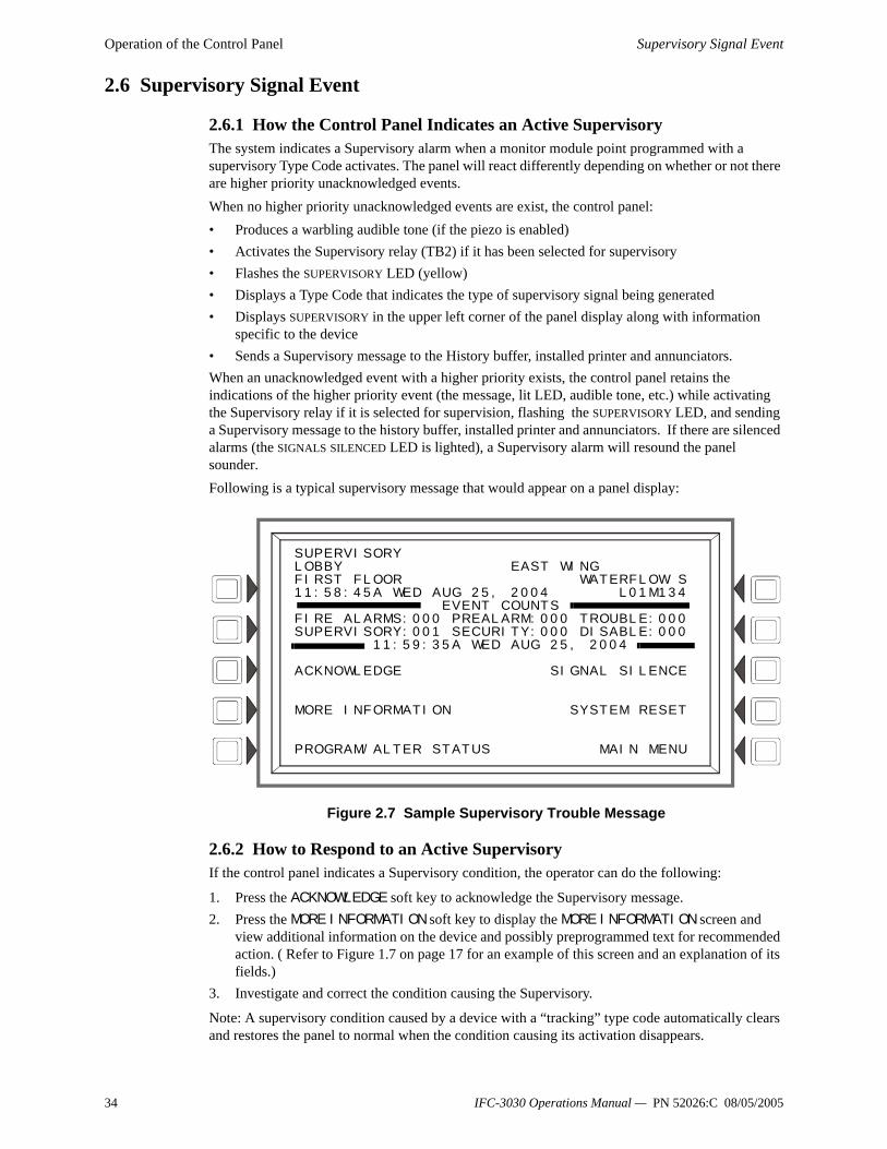
Operation of the Control Panel Supervisory Signal Event
2.6 Supervisory Signal Event
2.6.1 How the Control Panel Indicates an Active SupervisoryThe system indicates a Supervisory alarm when a monitor module point programmed with a supervisory Type Code activates. The panel will react differently depending on whether or not there are higher priority unacknowledged events.When no higher priority unacknowledged events are exist, the control panel:• Produces a warbling audible tone (if the piezo is enabled)• Activates the Supervisory relay (TB2) if it has been selected for supervisory• Flashes the SUPERVISORY LED (yellow)• Displays a Type Code that indicates the type of supervisory signal being generated• Displays SUPERVISORY in the upper left corner of the panel display along with information
specific to the device• Sends a Supervisory message to the History buffer, installed printer and annunciators.When an unacknowledged event with a higher priority exists, the control panel retains the indications of the higher priority event (the message, lit LED, audible tone, etc.) while activating the Supervisory relay if it is selected for supervision, flashing the SUPERVISORY LED, and sending a Supervisory message to the history buffer, installed printer and annunciators. If there are silenced alarms (the SIGNALS SILENCED LED is lighted), a Supervisory alarm will resound the panel sounder.Following is a typical supervisory message that would appear on a panel display:
Figure 2.7 Sample Supervisory Trouble Message
2.6.2 How to Respond to an Active SupervisoryIf the control panel indicates a Supervisory condition, the operator can do the following:
1. Press the ACKNOWLEDGE soft key to acknowledge the Supervisory message.2. Press the MORE INFORMATION soft key to display the MORE INFORMATION screen and
view additional information on the device and possibly preprogrammed text for recommended action. ( Refer to Figure 1.7 on page 17 for an example of this screen and an explanation of its fields.)
3. Investigate and correct the condition causing the Supervisory.
Note: A supervisory condition caused by a device with a “tracking” type code automatically clears and restores the panel to normal when the condition causing its activation disappears.
SUPERVISORY LOBBY EAST WING FIRST FLOOR WATERFLOW S11:58:45A WED AUG 25, 2004 L01M134 EVENT COUNTS FIRE ALARMS:000 PREALARM:000 TROUBLE:000SUPERVISORY:001 SECURITY:000 DISABLE:000 11:59:35A WED AUG 25, 2004 ACKNOWLEDGE SIGNAL SILENCE MORE INFORMATION SYSTEM RESET PROGRAM/ALTER STATUS MAIN MENU
34 IFC-3030 Operations Manual — PN 52026:C 08/05/2005

Supervisory Signal Event Operation of the Control Panel
4. Press the SYSTEM RESET soft key to clear any supervisory condition caused by a device with a latching type code: the supervisory will not automatically clear when the condition causing it is cleared. Latching supervisory type codes are WATERFLOW S, LATCH SUPERV, and SPRINKLR SYS.
The panel will send a system normal message to the History buffer, installed printer and annunciators.
2.6.3 How to Interpret Type CodesThe Type Code that displays in the Supervisory message indicates the function of the point that initiates the Supervisory. For example, a monitor module with a WATERFLOW S Type Code means that the module monitors the state of a waterflow switch. If the Type ID code is unfamiliar, refer to "Software Type ID Codes" on page 63. This appendix is an alphabetical list of Type ID codes and an explanation of each.
IFC-3030 Operations Manual — PN 52026:C 08/05/2005 35
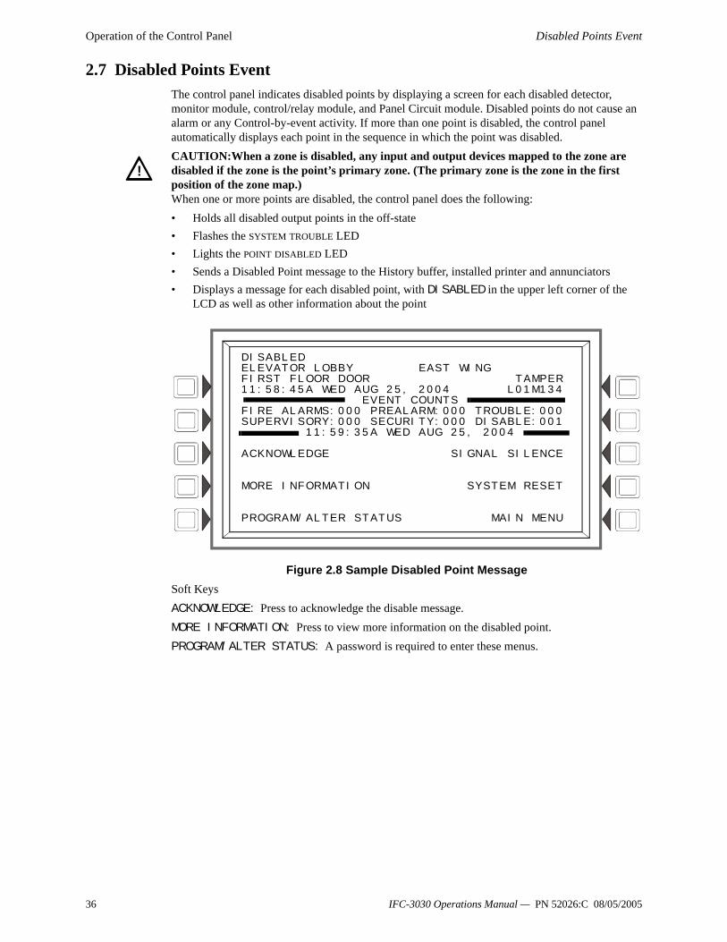
Operation of the Control Panel Disabled Points Event
2.7 Disabled Points EventThe control panel indicates disabled points by displaying a screen for each disabled detector, monitor module, control/relay module, and Panel Circuit module. Disabled points do not cause an alarm or any Control-by-event activity. If more than one point is disabled, the control panel automatically displays each point in the sequence in which the point was disabled.CAUTION:When a zone is disabled, any input and output devices mapped to the zone are disabled if the zone is the point’s primary zone. (The primary zone is the zone in the first position of the zone map.)When one or more points are disabled, the control panel does the following:• Holds all disabled output points in the off-state• Flashes the SYSTEM TROUBLE LED• Lights the POINT DISABLED LED• Sends a Disabled Point message to the History buffer, installed printer and annunciators• Displays a message for each disabled point, with DISABLED in the upper left corner of the
LCD as well as other information about the point
Figure 2.8 Sample Disabled Point MessageSoft KeysACKNOWLEDGE: Press to acknowledge the disable message.MORE INFORMATION: Press to view more information on the disabled point.PROGRAM/ALTER STATUS: A password is required to enter these menus.
!
DISABLEDELEVATOR LOBBY EAST WINGFIRST FLOOR DOOR TAMPER11:58:45A WED AUG 25, 2004 L01M134
EVENT COUNTSFIRE ALARMS:000 PREALARM:000 TROUBLE:000SUPERVISORY:000 SECURITY:000 DISABLE:001
11:59:35A WED AUG 25, 2004
ACKNOWLEDGE SIGNAL SILENCE
MORE INFORMATION SYSTEM RESET
PROGRAM/ALTER STATUS MAIN MENU
36 IFC-3030 Operations Manual — PN 52026:C 08/05/2005
Active Event Operation of the Control Panel
2.8 Active Event
2.8.1 How the Control Panel Indicates an Active Fire Control PointA point with a Type ID of FIRE CONTROL is used for air handler shutdown, intended to override normal operating automatic functions.Activation of a FIRE CONTROL point causes the control panel to do the following:• Initiates the monitor module Control-by-Event• Send a message to the panel display, History buffer, installed printer and annunciators• Does NOT light an indicator at the control panel• Displays ACTIVE in the upper left corner of the LCD, as well as a FIRE CONTROL Type Code
and other information specific to the device
2.8.2 How the Control Panel Indicates an Active Non-fire PointA point with a Type ID of NON-FIRE is used for energy management or other non-fire situations. NON-FIRE point operation does not affect control panel operation, nor does it display a message at the panel LCD. Activation of a NON-FIRE point activates CBE—but does not cause any indication on the control panel. For example, you can program a NON-FIRE point to turn lights in a zone to a lower setting when activated. In this case, when the point activates the control panel activates the point’s CBE to turn the lights down without any audio or visual indication on the control panel.
IFC-3030 Operations Manual — PN 52026:C 08/05/2005 37
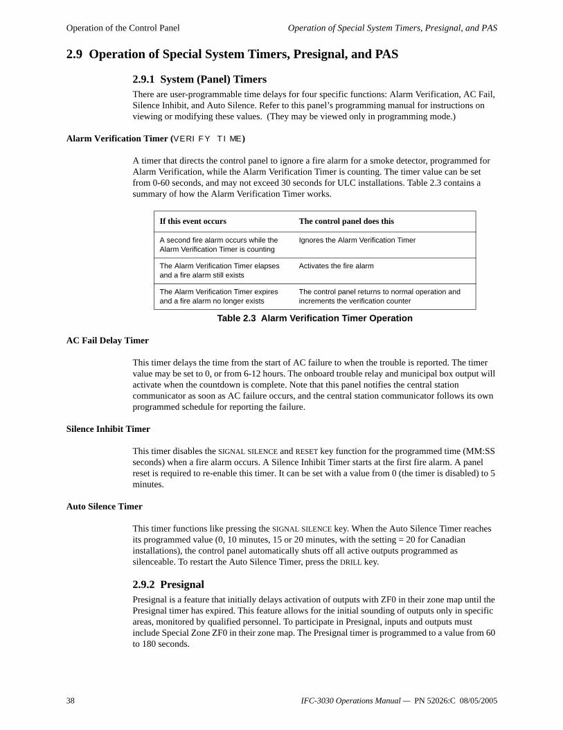
Operation of the Control Panel Operation of Special System Timers, Presignal, and PAS
2.9 Operation of Special System Timers, Presignal, and PAS
2.9.1 System (Panel) TimersThere are user-programmable time delays for four specific functions: Alarm Verification, AC Fail, Silence Inhibit, and Auto Silence. Refer to this panel’s programming manual for instructions on viewing or modifying these values. (They may be viewed only in programming mode.)
Alarm Verification Timer (VERIFY TIME )
A timer that directs the control panel to ignore a fire alarm for a smoke detector, programmed for Alarm Verification, while the Alarm Verification Timer is counting. The timer value can be set from 0-60 seconds, and may not exceed 30 seconds for ULC installations. Table 2.3 contains a summary of how the Alarm Verification Timer works.
Table 2.3 Alarm Verification Timer Operation
AC Fail Delay Timer
This timer delays the time from the start of AC failure to when the trouble is reported. The timer value may be set to 0, or from 6-12 hours. The onboard trouble relay and municipal box output will activate when the countdown is complete. Note that this panel notifies the central station communicator as soon as AC failure occurs, and the central station communicator follows its own programmed schedule for reporting the failure.
Silence Inhibit Timer
This timer disables the SIGNAL SILENCE and RESET key function for the programmed time (MM:SS seconds) when a fire alarm occurs. A Silence Inhibit Timer starts at the first fire alarm. A panel reset is required to re-enable this timer. It can be set with a value from 0 (the timer is disabled) to 5 minutes.
Auto Silence Timer
This timer functions like pressing the SIGNAL SILENCE key. When the Auto Silence Timer reaches its programmed value (0, 10 minutes, 15 or 20 minutes, with the setting = 20 for Canadian installations), the control panel automatically shuts off all active outputs programmed as silenceable. To restart the Auto Silence Timer, press the DRILL key.
2.9.2 PresignalPresignal is a feature that initially delays activation of outputs with ZF0 in their zone map until the Presignal timer has expired. This feature allows for the initial sounding of outputs only in specific areas, monitored by qualified personnel. To participate in Presignal, inputs and outputs must include Special Zone ZF0 in their zone map. The Presignal timer is programmed to a value from 60 to 180 seconds.
If this event occurs The control panel does this
A second fire alarm occurs while the Alarm Verification Timer is counting
Ignores the Alarm Verification Timer
The Alarm Verification Timer elapses and a fire alarm still exists
Activates the fire alarm
The Alarm Verification Timer expires and a fire alarm no longer exists
The control panel returns to normal operation and increments the verification counter
38 IFC-3030 Operations Manual — PN 52026:C 08/05/2005

Operation of Special System Timers, Presignal, and PAS Operation of the Control Panel
How the Panel Indicates a Presignal Alarm
When an initiating device participating in Presignal goes into alarm, the panel LCD displays a fire alarm message. ( Refer to “Fire Alarm Event” on page 23.) If a second alarm occurs while the Presignal timer is counting down, the control panel aborts the Presignal timer countdown and activates all programmed outputs. The fire alarm LED flashes and the panel sounder pulses a steady tone. The control panel latches until the alarm is corrected and the SYSTEM RESET key is pressed to reset the panel.
How to Respond to a Presignal Alarm
Once the Presignal timer has begun counting down, the operator has the duration of the countdown time to respond to the alarm before the control panel automatically activates all outputs with ZF0 in their zone map and CBE linkage to the alarm. The operator can reset the panel if the alarm is determined false, or press DRILL to evacuate the building immediately.
2.9.3 PAS (Positive Alarm Sequence)PAS (Positive Alarm Sequence), used in conjunction with Presignal, allows a 15-second time period for acknowledging an alarm signal from a fire detection/initiating device. If the alarm is not acknowledged within 15 seconds, all programmed outputs activate. If the alarm is acknowledged within 15 seconds, the control panel will enter Presignal mode as described above. The PAS Inhibit switch can be used to turn off the PAS delay timer when the control panel is unattended.
IFC-3030 Operations Manual — PN 52026:C 08/05/2005 39

Operation of the Control Panel Operation of Special System Timers, Presignal, and PAS
40 IFC-3030 Operations Manual — PN 52026:C 08/05/2005

Point Select Screen Read Status
Section 3 Read StatusThis section contains instructions and screen illustrations for Read Status functions and menus using the IFC-3030 display.Read Status allows viewing of detailed device status information without entering a password or halting full fire protection. Information can be viewed while a fire alarm or trouble condition exists. Read Status screens are refreshed periodically with up-to-date information.Read Status can be reached from the Main Menu screen, which is accessible from the System Normal screen and from most other screens by pressing the BACK soft key until it displays. (Refer to Figure 1.5 for an illustration of the Main Menu screen.)Press the READ STATUS soft key on the Main Menu screen to bring up the following screen.
3.1 Point Select ScreenWhen READ STATUS is pressed at the Main Menu, the following screen appears.
Figure 3.1 Point Select Screen for Read StatusSoft KeysPOINT SELECT - Pressing this soft key scrolls through the various device types. The types and their address formats are illustrated in Table 3.1.
Table 3.1 Address Formats
Enter an address to view its attributes (the cursor will be in the underlined section).
Type Address Format
Detector LyyDzzz L=Loop, yy=Loop number (1-10)D=Detector, zzz=Detector address (1-159)
Module LyyMzzz L=Loop, yy=Loop number (1-10)M=Module, zzz=Module address (1-159)
Panel Circuit Pyy.z P=Panel circuit, yy=Panel Module Number (1-12), z=panel module point (1-8)General Zone Zyyy Z=Zone, yyy=Zone number (0-999)Logic Zone ZLyyyy ZL=Logic Zone, yyyy=Logic Zone number(1-1000)Release Zone Ryy R=Releasing Zone, yy=Releasing Zone number (00-09)Special Function Zone
ZFxx ZF=Special Function Zone, x=Special Function Zone number (00, 01, 02, 03, 04, 05, 09)
Trouble Zone ZTyyy ZT=Trouble Zone, yyy=Trouble Zone number (1-100)Annunciator AxxPyy A=Annunciator, xx=ACS address (1-32), P=Point, yy=Point address (1-96)
LAKEVIEW GENERAL HOSPITAL SYSTEM NORMAL 10:22:34A FRI SEP 24, 2004 POINT SELECT POINT SELECT: LyyDzzz (DETECTOR) NEXT POINT ACCEPT PREVIOUS POINT BACK
IFC-3030 Operations Manual — PN 52026:C 08/05/2005 41

Read Status Smoke Detector
NEXT POINT/PREVIOUS POINT - Press to view next or previous point.ACCEPT - Press to accept the displayed point for further viewing.Pressing the ACCEPT soft key on the Point Select Screen will display the information that corresponds to the chosen point. Each point type has its own screen.
Note: The first four lines of the display may indicate an alarm for a point unrelated to the requested point information displayed below them.
3.2 Smoke DetectorWhen a detector address is entered into the Point Select Screen and the ACCEPT soft key is pressed, the following screen will display if the detector is a smoke detector.
Figure 3.2 Smoke Detector Screen - Read StatusDisplayLines 1- 4 - This could display any current event message, or, as in this example, the System Normal message.Line 5 - This line contains the screen title and the address of the point being read.The area between the separator lines, lines 6-14, shows all information concerning the selected point, which is L03D052 in the above example.Line 6 - Line 6 displays two statistics that display for inputs (detectors and modules) and zones; in the above example they are:
AUTOMATIC INACTIVEThe first field displays the point control. There are three designations that could appear in this field
The second field displays the point status. There are three designations that could appear in this field.
The device is a detector (an input device) so by referring to the descriptions below, it can be
Point Control Designation DescriptionAUTOMATIC The point is being controlled automatically by the panel.DISABLED The point has been disabled by an outside source.TROUBLE The point is in a trouble state and is no longer functioning automatically.
Point Status Designation DescriptionINACTIVE The point is currently reporting no events.ACTIVE The point is currently in an off-normal status.PRE-ALARM The point is currently in a prealarm status.
LAKEVIEW GENERAL HOSPITALSYSTEM NORMAL
10:22:34A FRI SEP 24, 2004READ ADDRESS: L03D052
AUTOMATIC INACTIVEELEVATOR LOBBY EAST WINGFIFTH FLOOR Z005 SMOKE(PHOTO)
Z005, Z027, Z066, , ,, , , , ,
VALUES: 011% OF ALARM, 045% OF PREALARM ALARM: 6= 1.66%, PREALARM: 3= 0.47%ACTION/STATUS: NONE/VERY CLEANPEAKS:56% VERIFY COUNT:02 CO-OP:D100,158
10:22:34A FRI SEP 24, 2004BACK
42 IFC-3030 Operations Manual — PN 52026:C 08/05/2005
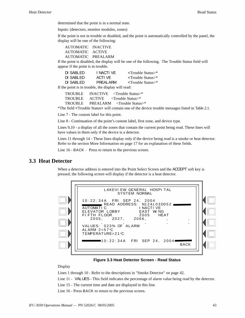
Heat Detector Read Status
determined that the point is in a normal state. Inputs: (detectors, monitor modules, zones)If the point is not in trouble or disabled, and the point is automatically controlled by the panel, the display will be one of the following:
AUTOMATIC INACTIVEAUTOMATIC ACTIVEAUTOMATIC PREALARM
If the point is disabled, the display will be one of the following. The Trouble Status field will appear if the point is in trouble.
DISABLED INACTIVE <Trouble Status>*DISABLED ACTIVE <Trouble Status>*DISABLED PREALARM <Trouble Status>*
If the point is in trouble, the display will read:TROUBLE INACTIVE <Trouble Status>*TROUBLE ACTIVE <Trouble Status>*TROUBLE PREALARM <Trouble Status>*
*The field <Trouble Status> will contain one of the device trouble messages listed in Table 2.1.Line 7 - The custom label for this point.Line 8 - Continuation of the point’s custom label, first zone, and device type.Lines 9,10 - a display of all the zones that contain the current point being read. These lines will have values in them only if the device is a detector.Lines 11 through 14 - These lines display only if the device being read is a smoke or heat detector. Refer to the section More Information on page 17 for an explanation of these fields.Line 16 - BACK - Press to return to the previous screen.
3.3 Heat DetectorWhen a detector address is entered into the Point Select Screen and the ACCEPT soft key is pressed, the following screen will display if the detector is a heat detector.
Figure 3.3 Heat Detector Screen - Read StatusDisplayLines 1 through 10 - Refer to the descriptions in "Smoke Detector" on page 42.Line 11 - VALUES - This field indicates the percentage of alarm value being read by the detector.Line 15 - The current time and date are displayed in this line.Line 16 - Press BACK to return to the previous screen.
LAKEVIEW GENERAL HOSPITAL SYSTEM NORMAL 10:22:34A FRI SEP 24, 2004 READ ADDRESS: N124L03D052 AUTOMATIC INACTIVE ELEVATOR LOBBY EAST WING FIFTH FLOOR Z005 HEAT Z005, Z027, Z066, , , , , , , ,VALUES: 023% OF ALARM ALARM 2=57 oC TEMPERATURE=21 oC 10:22:34A FRI SEP 24, 2004 BACK
IFC-3030 Operations Manual — PN 52026:C 08/05/2005 43

Read Status Monitor Module
3.4 Monitor ModuleWhen a module address is entered into the Point Select Screen and the ACCEPT soft key is pressed, the following screen will display if the point is a monitor module.
Figure 3.4 Monitor Module Screen - Read StatusDisplayLines 1 through 10 - Refer to the descriptions in "Smoke Detector" on page 42.Lines 13 and 14 - When a module is monitoring an AMPS-24 or an ACPS-2406, information will appear in these lines in the following format.
BATTERY VOLTAGE: 27.9 VOLTSCHARGER CURRENT: 0.0 AMPS
Line 15 - The current time and date are displayed in this line.Line 16 - Press BACK to return to the previous screen.
3.5 Control ModuleWhen a module address is entered into the Point Select Screen and the ACCEPT soft key is pressed, the following screen will display if the module is a control module.
Figure 3.5 Control Module Screen - Read StatusDisplayLines 1 through 10 - Refer to the descriptions in "Smoke Detector" on page 42 with the exception of line 6, which is described below.
LAKEVIEW GENERAL HOSPITAL SYSTEM NORMAL 10:22:34A FRI SEP 24, 2004 READ ADDRESS: L03M052 AUTOMATIC INACTIVE ELEVATOR LOBBY EAST WING FIFTH FLOOR Z005 PULL STATION Z022, Z027, Z066, , , , , , , , 10:22:34A FRI SEP 24, 2004 BACK
Battery voltage and charger current will appear in lines 13 and 14 if the module is monitoring an AMPS-24 or an ACPS-2406. See text below.
LAKEVIEW GENERAL HOSPITAL SYSTEM NORMAL 10:22:34A FRI SEP 24, 2004 READ ADDRESS: L03M052 AUTOMATIC OFF ELEVATOR LOBBY EAST WING FIFTH FLOOR Z005 CONTROL Z005, Z027, Z066, , , , , , , , WALK TEST: YES SWITCH INHIBIT: YESSILENCEABLE: YES - RESOUND FIRE 10:22:34A FRI SEP 24, 2004 BACK
44 IFC-3030 Operations Manual — PN 52026:C 08/05/2005

Control Module Read Status
Line 6 - This line displays statistics that display for control module output points; in the above example they are:
AUTOMATIC OFFThe first field displays the point control. There are four designations that could appear in this field
The second field displays the point status. There are three designations that could appear in this field.
The device is a control module (an output device) so by referring to the descriptions below, it can be determined that the point is in a normal state.Outputs: (Control Modules)If the point is not in trouble or disabled and the status is Automatic, the display will read:
AUTOMATIC OFFAUTOMATIC ONAUTOMATIC OFF-HOOK
If the point has been forced into a manual control state, the display will read as follows. <Trouble Status> will appear when there is a point trouble.
MANUAL OFF <Trouble Status>*MANUAL ON <Trouble Status>*MANUAL OFF-HOOK <Trouble Status>*
If the point is disabled, the display will read as follows. <Trouble Status> will appear when there is a point trouble.
DISABLED OFF <Trouble Status>*DISABLED ON <Trouble Status>*DISABLED OFF-HOOK <Trouble Status>*
If the point is in trouble, the display will read:TROUBLE OFF <Trouble Status>*TROUBLE ON <Trouble Status>*TROUBLE OFF-HOOK <Trouble Status>**The field <Trouble Status> will contain one of the device trouble messages listed in Table 2.1.
Line 11 - blank.Line 12 - WALK TEST - Displays YES if the device sounds during audible Walk Test.Line 13 - SILENCEABLE - Displays YES if the operator can manually silence an activated output. The output resounds for fire.Line 14 - SWITCH INHIBIT: YES - Displays YES if the operator can not manually activate an output.Line 15 - The current time and date are displayed in this line.Line 16 - Press BACK to return to the previous screen.
Point Control Designation
Description
AUTOMATIC The point is being controlled automatically by the panel.MANUAL The point has been forced into manual control state by an outside source.DISABLED A status change other than a change to MANUAL control has caused the
point to go off automatic control.TROUBLE
Point Status Designation
Description
OFF The point is currently not activated.ON The point is currently activated.OFF-HOOK The telephone point is currently off-hook.
IFC-3030 Operations Manual — PN 52026:C 08/05/2005 45

Read Status Panel Input
3.6 Panel InputWhen a Panel Input address is entered into the Point Select Screen and the ACCEPT soft key is pressed, the following screen will display.
Figure 3.6 Panel Input Screen - Read StatusDisplayLines 1 through 10 - Refer to the descriptions in "Smoke Detector" on page 42.Line 15 - Current time and date.
3.7 Panel OutputWhen a Panel Output address is entered into the Point Select Screen and the ACCEPT soft key is pressed, the following screen will display
Figure 3.7 Panel Output Screen - Read StatusDisplayLines 1 through 10 - Refer to the descriptions in "Smoke Detector" on page 42 with the exception of line 6. Refer to the section Control Module on page 44 for a description of line 6.WALK TEST - Displays YES if the device sounds during audible Walk Test.SILENCEABLE - Displays YES if the operator can manually silence an activated output. The output resounds for fire.SWITCH INHIBIT: NO - Displays NO if the operator can manually activate an output.
LAKEVIEW GENERAL HOSPITAL SYSTEM NORMAL 10:22:34A FRI SEP 24, 2004 READ ADDRESS: P01.4 AUTOMATIC INACTIVEELEVATOR LOBBY EAST WING FIFTH FLOOR Z005 SMOKE CONVEN Z005, Z027, Z066, , , , , , , , VERIFY COUNT:0 10:22:34A FRI SEP 24, 2004 BACK
LAKEVIEW GENERAL HOSPITAL SYSTEM NORMAL
10:22:34A FRI SEP 24, 2004 READ ADDRESS: P01.4 AUTOMATIC OFFELEVATOR LOBBY EAST WING FIFTH FLOOR Z005 CONTROL Z005, Z027, Z066, , , , , , , ,
WALK TEST: YESSWITCH INHIBIT: YESSILENCEABLE: YES - RESOUND FIRE 10:22:34A FRI SEP 24, 2004
BACK
46 IFC-3030 Operations Manual — PN 52026:C 08/05/2005
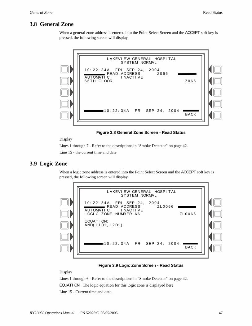
General Zone Read Status
3.8 General ZoneWhen a general zone address is entered into the Point Select Screen and the ACCEPT soft key is pressed, the following screen will display
Figure 3.8 General Zone Screen - Read StatusDisplayLines 1 through 7 - Refer to the descriptions in "Smoke Detector" on page 42.Line 15 - the current time and date
3.9 Logic ZoneWhen a logic zone address is entered into the Point Select Screen and the ACCEPT soft key is pressed, the following screen will display
Figure 3.9 Logic Zone Screen - Read StatusDisplayLines 1 through 6 - Refer to the descriptions in "Smoke Detector" on page 42.EQUATION: The logic equation for this logic zone is displayed hereLine 15 - Current time and date.
LAKEVIEW GENERAL HOSPITAL SYSTEM NORMAL 10:22:34A FRI SEP 24, 2004 READ ADDRESS: Z066 AUTOMATIC INACTIVE66TH FLOOR Z066 10:22:34A FRI SEP 24, 2004 BACK
LAKEVIEW GENERAL HOSPITAL SYSTEM NORMAL 10:22:34A FRI SEP 24, 2004 READ ADDRESS: ZL0066 AUTOMATIC INACTIVELOGIC ZONE NUMBER 66 ZL0066 EQUATION: AND(L1D1,L2D1) 10:22:34A FRI SEP 24, 2004 BACK
IFC-3030 Operations Manual — PN 52026:C 08/05/2005 47
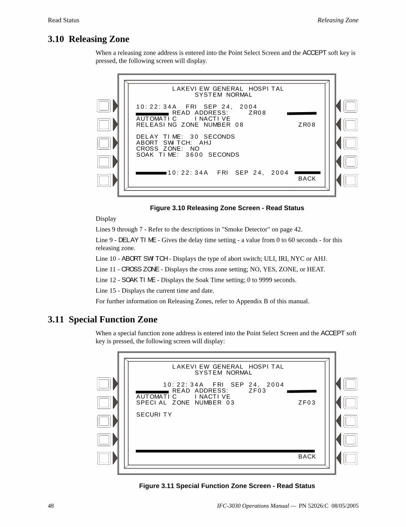
Read Status Releasing Zone
3.10 Releasing ZoneWhen a releasing zone address is entered into the Point Select Screen and the ACCEPT soft key is pressed, the following screen will display.
Figure 3.10 Releasing Zone Screen - Read StatusDisplayLines 9 through 7 - Refer to the descriptions in "Smoke Detector" on page 42.Line 9 - DELAY TIME - Gives the delay time setting - a value from 0 to 60 seconds - for this releasing zone.Line 10 - ABORT SWITCH - Displays the type of abort switch; ULI, IRI, NYC or AHJ.Line 11 - CROSS ZONE - Displays the cross zone setting; NO, YES, ZONE, or HEAT.Line 12 - SOAK TIME - Displays the Soak Time setting; 0 to 9999 seconds.Line 15 - Displays the current time and date.For further information on Releasing Zones, refer to Appendix B of this manual.
3.11 Special Function ZoneWhen a special function zone address is entered into the Point Select Screen and the ACCEPT soft key is pressed, the following screen will display:
Figure 3.11 Special Function Zone Screen - Read Status
LAKEVIEW GENERAL HOSPITAL SYSTEM NORMAL 10:22:34A FRI SEP 24, 2004 READ ADDRESS: ZR08 AUTOMATIC INACTIVERELEASING ZONE NUMBER 08 ZR08 DELAY TIME: 30 SECONDS ABORT SWITCH: AHJ CROSS ZONE: NO SOAK TIME: 3600 SECONDS 10:22:34A FRI SEP 24, 2004 BACK
LAKEVIEW GENERAL HOSPITALSYSTEM NORMAL
10:22:34A FRI SEP 24, 2004READ ADDRESS: ZF03
AUTOMATIC INACTIVESPECIAL ZONE NUMBER 03 ZF03
SECURITY
BACK
48 IFC-3030 Operations Manual — PN 52026:C 08/05/2005

Trouble Zone Read Status
DisplayLines 1 through 6 - Refer to the descriptions in "Smoke Detector" on page 42.Line 7 - The special zone number and function is displayed here.
3.12 Trouble ZoneWhen a trouble zone address is entered into the Point Select Screen and the ACCEPT soft key is pressed, the following screen will display.
Figure 3.12 Trouble Zone Screen - Read StatusDisplayLines 1 through 6 - Refer to the descriptions in "Smoke Detector" on page 42.EQUATION: The equation for this trouble zone is displayed here.Line 15 - Current time and date.
3.13 AnnunciatorWhen an annunciator address is entered into the Point Select Screen and the ACCEPT soft key is pressed, the following screen will display if the point is a monitor module.
Figure 3.13 Annunciator Screen - Read Status
LAKEVIEW GENERAL HOSPITAL SYSTEM NORMAL 10:22:34A FRI SEP 24, 2004 READ ADDRESS: ZT008 AUTOMATIC INACTIVETROUBLE ZONE NUMBER 008 ZT008 EQUATION: AND(T15,T16) 10:22:34A FRI SEP 24, 2004 BACK
LAKEVIEW GENERAL HOSPITALSYSTEM NORMAL
10:22:34A FRI SEP 24, 2004READ ADDRESS: A08P09
MODE: CONTROLACTIVE LED: OFFTROUBLE LED: OFF
SOURCE: L01M001 L01M002
BACK
IFC-3030 Operations Manual — PN 52026:C 08/05/2005 49

Read Status Annunciator
DisplayLines 1- 4 - This could display any current event message, or, as in this example, the System Normal messageLine 5 - Screen title and the address of the point being read.Line 6 - Displays the annunciator mode.Line 7 - Displays the state of the active LED.Line 8 - Displays the state of the trouble LED.Line 10 - Displays the annunciator source(s).
50 IFC-3030 Operations Manual — PN 52026:C 08/05/2005

Events History Viewing and Printing History Information
Section 4 Viewing and Printing History InformationThe control panel maintains a history file of alarm, trouble, supervisory, and security events, each with a time/date stamp. An alarm history is maintained in a buffer that can include up to 1000 events. All events, including alarms, are included in a 4000-event buffer. History events may be viewed onscreen, and a printed list may be generated.To choose a history display screen:Press the HISTORY SELECT soft key at the Main Menu. A menu screen titled History Select will appear. (Refer to Figure 1.9.)
Press the soft key for the type of event history desired to view all of those types of events that are in the history buffer,
ORPress the TIME/DATE INTERVAL or POINT RANGE soft key to choose limiting parameters for what will display onscreen.
The following sections illustrate and explain the history displays.
4.1 Events HistoryPressing a soft key on the History Select screen will display the history for whatever event type chosen. If the ALL EVENTS soft key is pressed, any events in the history file will display, no matter what the type.The screen below is an example of what displays when the ALL EVENTS soft key is pressed. The displayed fields are the same for each event type.
Figure 4.1 Event History ScreenDisplayLines 1-4: Displays any current event message, or, as in this example, the System Normal messageLine 5: Screen title. It will vary depending on the history type chosen for viewing. For example, it will display ALARM HISTORY if the ALARMS ONLY soft key is pressed at the History Select screen.Line 6: Queue location of event that is described in lines 8-11: In the above example, the detector trouble is the fourth of 17 events in the history file.Lines 8 through 11 give more information about the event. Refer to “Event Reporting Format” on page 13 for an explanation of these fields.Soft KeysNEXT EVENT - Press to view next event (In the above example, event 005 of 017).
LAKEVIEW GENERAL HOSPITAL SYSTEM NORMAL 11:58:45A WED AUG 25, 2004 EVENT HISTORY EVENT 004 OF 017 TROUBLE DETECTOR FAILED TESTELEVATOR LOBBY EAST WING FIFTH FLOOR Z005 SMOKE(LASER)10:43:45A TUE AUG 24, 2004 L03D157 NEXT EVENT PRINT EVENT HISTORY PREVIOUS EVENT BACK
IFC-3030 Operations Manual — PN 52026:C 08/05/2005 51

Viewing and Printing History Information Time and Date Range Selection for All Events
PREVIOUS EVENT - Press to view previous event (In the above example, event 003 of 017). PRINT “xxx” HISTORY - Press to print the history for the event(s) chosen. (In the above example, all 17 events). The report will look like this:
4.2 Time and Date Range Selection for All EventsPressing the Time/Date Interval soft key on the History Select screen displays the Time & Date Range Select screen. This screen allows for selection of a time period that defines the range of events to be viewed and/or printed.
Figure 4.2 Time & Date Range Select ScreenDisplaySee description in "Events History" on page 51 for lines 1-5.Soft KeysSTART TIME: - Use the keypad to enter a start time for event viewing in the following format:
HH:MMA/P DDD MM/DD/YYEND TIME: - Use the keypad to enter an end time for event viewing.EVENT TYPE: - Press this soft key to scroll through the following: ALL EVENTS, ALARMS ONLY, TROUBLES ONLY, SUPERVISORY ONLY, SECURITY ONLY, OTHER ONLY. Stop scrolling at the desired event type.ACCEPT: - When entries are made, press this soft key to proceed to the All Events in Interval Screen.All Events in Interval ScreenThis screen is the same as the Event History screen, except for its title. Refer to Figure 4.1 on page 51.
******EVENT HISTORY*************************************************************TROUBLE TM4 NO ANSWER 08:52:05P SAT AUG 14, 2004
ACK TROUBLE TM4 NO ANSWER 08:53:35P SAT AUG 14, 2004
CLEAR TROUBLE TM4 NO ANSWER 08:54:05P SAT AUG 14, 2004
********************************************************************************
LAKEVIEW GENERAL HOSPITAL SYSTEM NORMAL 11:58:45A WED AUG 25, 2004 TIME & DATE RANGE SELECT START TIME: 12:00A THU 08/19/04 END TIME: 02:00P MON 08/23/04 EVENT TYPE: ALL EVENTS ACCEPT BACK
52 IFC-3030 Operations Manual — PN 52026:C 08/05/2005

Point Range Select for All Events in Range Viewing and Printing History Information
4.3 Point Range Select for All Events in RangePressing the Point Range soft key on the Local History Select screen displays the Point Range Select screen. This screen allows for selection of a beginning and an end point that defines the range of events to be viewed and/or printed.Range is selected in the following order:
1. Loop 1 Detectors2. Loop 2 Detectors, etc...3. Loop 10 Detectors4. Loop 1 Modules5. Loop 2 Modules, etc...This FACP can have up to 10 loops, which would all follow the above order for range selection.
1. Loop 10 Modules2. Panel Circuits The range selected below includes all supervisory event types for every point: the selection begins with the first detector on loop one and ends with the last panel circuit.
Figure 4.3 Point Range Select ScreenDisplaySee description in "Events History" on page 51 for lines 1-5.Soft KeysSTART POINT: - Press this key to scroll through the list of various device types: the format will change for each device. Stop at the desired format/device type, then use the keypad to enter a start point for event viewing.END POINT: - Press this key to scroll through the list of various device types: the format will change for each device. Stop at the desired format/device type, then use the keypad to enter an end point for event viewing.EVENT TYPE: - Press this soft key to scroll through the following: ALL EVENTS, ALARMS ONLY, TROUBLES ONLY, SUPERVISORY ONLY, SECURITY ONLY, OTHER ONLY. Stop scrolling at the desired event type.ACCEPT: - When entries are made, press this soft key to proceed to the All Events in Range Screen.All Events in Range ScreenThis screen is the same as the Event History screen, except for its title. Refer to Figure 4.1 on page 51.
LAKEVIEW GENERAL HOSPITAL SYSTEM NORMAL 11:58:45A WED AUG 25, 2004 POINT RANGE SELECT START POINT: L01D001 (DETECTOR) END POINT: P12.8 (MODULE) EVENT TYPE: SUPERVISORY ACCEPT BACK
IFC-3030 Operations Manual — PN 52026:C 08/05/2005 53

Viewing and Printing History Information Point Range Select for All Events in Range
54 IFC-3030 Operations Manual — PN 52026:C 08/05/2005
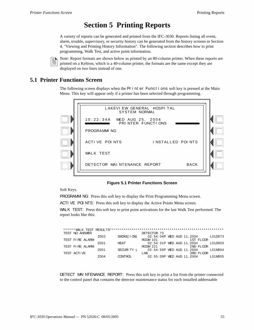
Printer Functions Screen Printing Reports
Section 5 Printing ReportsA variety of reports can be generated and printed from the IFC-3030. Reports listing all event, alarm, trouble, supervisory, or security history can be generated from the history screens in Section 4, "Viewing and Printing History Information". The following section describes how to print programming, Walk Test, and active point information.
Note: Report formats are shown below as printed by an 80-column printer. When these reports are printed on a Keltron, which is a 40-column printer, the formats are the same except they are displayed on two lines instead of one.
5.1 Printer Functions ScreenThe following screen displays when the Printer Functions soft key is pressed at the Main Menu. This key will appear only if a printer has been selected through programming.
Figure 5.1 Printer Functions ScreenSoft KeysPROGRAMMING: Press this soft key to display the Print Programming Menu screen. ACTIVE POINTS: Press this soft key to display the Active Points Menu screen.WALK TEST: Press this soft key to print point activations for the last Walk Test performed. The report looks like this:
DETECT MAINTENANCE REPORT: Press this soft key to print a list from the printer connected to the control panel that contains the detector maintenance status for each installed addressable
LAKEVIEW GENERAL HOSPITAL SYSTEM NORMAL 10:22:34A WED AUG 25, 2004 PRINTER FUNCTIONS PROGRAMMING ACTIVE POINTS INSTALLED POINTS WALK TEST DETECTOR MAINTENANCE REPORT BACK
******WALK TEST RESULTS*********************************************************TEST NO ANSWER DETECTOR 73 Z003 SMOKE(ION) 02:54:04P WED AUG 11,2004 L01D073TEST FIRE ALARM ROOM 101 1ST FLOOR Z001 HEAT 02:54:31P WED AUG 11,2004 L01D003TEST FIRE ALARM ROOM 221 2ND FLOOR Z001 SECURITY L 02:54:59P WED AUG 11,2004 L01M004TEST ACTIVE LAB 3RD FLOOR Z004 CONTROL 02:55:09P WED AUG 11,2004 L01M005
IFC-3030 Operations Manual — PN 52026:C 08/05/2005 55

Printing Reports Print Programming Menu Screen
detector. The report looks like this:
INSTALLED POINTS: Press this soft key to display the Installed Points Menu screen.
5.2 Print Programming Menu ScreenThis screen displays when the PROGRAMMING soft key is pressed on the PRINTER FUNCTIONS screen. Refer to Figure 5.1 on page 55).
Figure 5.2 Print Programming Screen
******DETECTOR MAINTENANCE******************************************************
NORMAL SMOKE(LASER) Detector L01D001 000330us 000340us Comp:000% Pk: 002%
Alarm: 000% PreAlarm: 000% A6P6 V000 L01D001
NORMAL SMOKE ACCLIM Detector L01D002 000030us 000000us Comp:000% Pk: 000%
Alarm: 000% PreAlarm: 000% A8P8 V000 L01D002
Field IdentificationDetector Maintenance Report
State LabelExtended
Label
Current reading of raw analog value in microseconds
Long term average of raw analog value in
microseconds
Compensation percentage
Detector peak
AddressPercent of alarm
threshold*
Percent of prealarm
threshold*
Verification count
Programmed alarm sensitivity*
Programmed prealarm sensitivity*
Alarm: 000% PreAlarm: 000% A6P6 V000 L01D001
NORMAL SMOKE(LASER) Detector L01D001 000330us 000340us Comp:000% Pk: 002%
* Whichever occupancy value is in effect when the report is printed.
PRINT PROGRAMMING MENU
NETWORK PARAMETERS LCD DISPLAY
PANEL SETTING
PANEL TIMERS MORE
BACK
56 IFC-3030 Operations Manual — PN 52026:C 08/05/2005
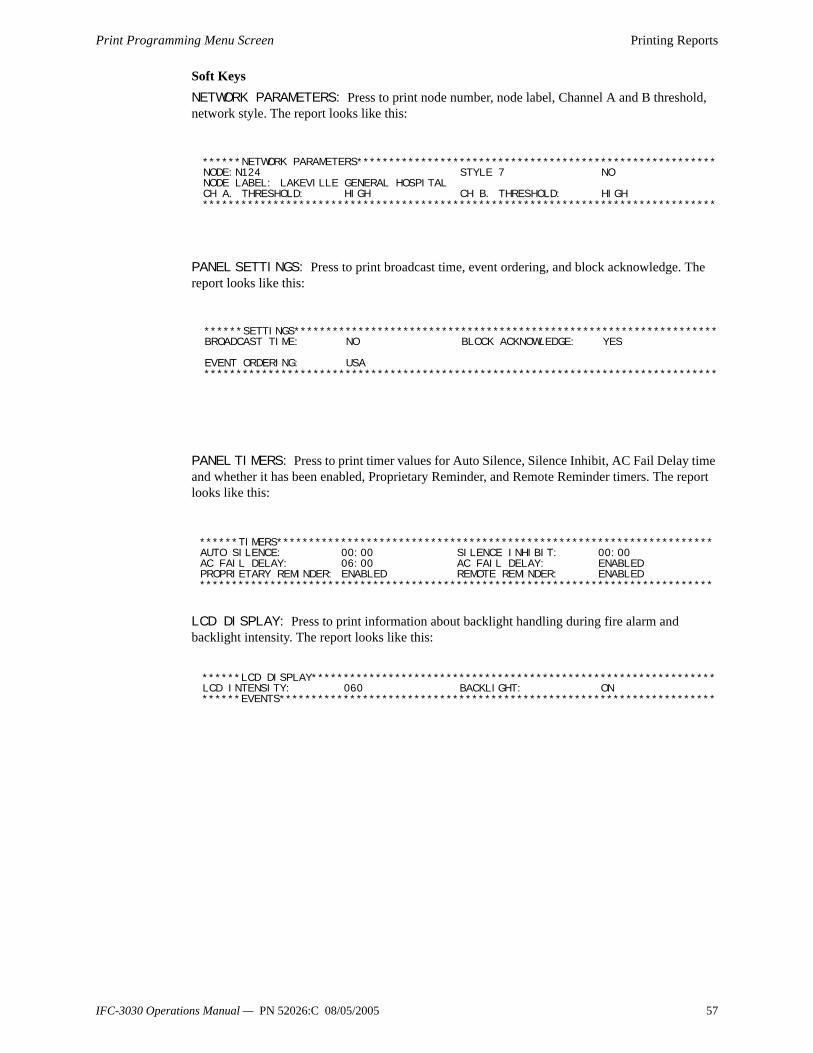
Print Programming Menu Screen Printing Reports
Soft KeysNETWORK PARAMETERS: Press to print node number, node label, Channel A and B threshold, network style. The report looks like this:
PANEL SETTINGS: Press to print broadcast time, event ordering, and block acknowledge. The report looks like this:
PANEL TIMERS: Press to print timer values for Auto Silence, Silence Inhibit, AC Fail Delay time and whether it has been enabled, Proprietary Reminder, and Remote Reminder timers. The report looks like this:
LCD DISPLAY: Press to print information about backlight handling during fire alarm and backlight intensity. The report looks like this:
******NETWORK PARAMETERS********************************************************NODE:N124 STYLE 7 NO NODE LABEL: LAKEVILLE GENERAL HOSPITAL CH A. THRESHOLD: HIGH CH B. THRESHOLD: HIGH ********************************************************************************
******SETTINGS******************************************************************BROADCAST TIME: NO BLOCK ACKNOWLEDGE: YES EVENT ORDERING: USA ********************************************************************************
******TIMERS********************************************************************AUTO SILENCE: 00:00 SILENCE INHIBIT: 00:00 AC FAIL DELAY: 06:00 AC FAIL DELAY: ENABLED PROPRIETARY REMINDER: ENABLED REMOTE REMINDER: ENABLED ********************************************************************************
******LCD DISPLAY***************************************************************LCD INTENSITY: 060 BACKLIGHT: ON ******EVENTS********************************************************************
IFC-3030 Operations Manual — PN 52026:C 08/05/2005 57

Printing Reports Print Programming Menu Screen (2)
5.3 Print Programming Menu Screen (2)The second PRINT PROGRAMMING MENU screen displays when MORE is pressed at the first PRINT PROGRAMMING MENU screen:
Figure 5.3 Print Programming ScreenSoft KeysSUPERVISION: Press to print information on power supply and printer monitoring. The report looks like this:
LOGIC EQUATIONS: Press to print all logic equations (1-1000). The report looks like this:
CUSTOM ACTION MESSAGES: Press to print all custom action messages (1-100). The report looks like this:
EVENT LOGGING: Press to print non-fire and output activations if these events have been chosen for logging during panel programming. The report looks like this:
PRINT PROGRAMMING MENU SUPERVISION EVENT LOGGING LOGIC EQUATIONS CUSTOM ACTION MESSAGES BACK
******SUPERVISION***************************************************************MAIN POWER SUPPLY ADDRESS: L01M006PRINTER: 80-columnTAMPER INPUT: NOAUXILIARY TROUBLE: NO********************************************************************************
******EQUATIONS*****************************************************************ZL001 AND(Z02,Z05,L2D121) ZL002 DEL(10:30:00,11:30:00,L1M140) ********************************************************************************
******CUSTOM ACTION MESSAGE*****************************************************CAM 1 GO TO ALARM SITE AND INVESTIGATE APPROACH THE ALARM LOCATION WITH CAUTION BRING CELL PHONE AND REPORT WHEN ON SITE CAM 2 CALL MANAGER WITH REPORT ********************************************************************************
******EVENT LOGGING*************************************************************NON-FIRE ACTIVATIONS:NO OUTPUT ACTIVATIONS: NO********************************************************************************
58 IFC-3030 Operations Manual — PN 52026:C 08/05/2005

Active Points Report Screen Printing Reports
5.4 Active Points Report ScreenThis screen displays when the ACTIVE POINTS soft key is pressed on the PRINTER FUNCTIONS screen (refer to Figure 5.1 on page 55).
Figure 5.4 Print Active Points ScreenSoft KeysThis screen provides a menu for printing a list of active points for whatever type of list is chosen. The soft key will display on the screen only if there is at least one event in the queue.
Note: For a printed list of history information, refer to the history screens in Section 4, "Viewing and Printing History Information".
5.5 Installed Points Report ScreenThis screen displays when the INSTALLED POINTS soft key is pressed on the PRINTER FUNCTIONS screen (refer to Figure 5.1 on page 55)
Figure 5.5 Print Programming ScreenSoft KeysSLC POINTS:Press to print information on installed SLC points. When the soft key is pressed, a field appears to allow choice of a single SLC or ALL. Toggle until the desired choice appears in
LAKEVIEW GENERAL HOSPITALSYSTEM NORMAL
10:22:34A FRI SEP 24, 2004 ACTIVE POINTS
ALARMS ONLY PREALARMS
TROUBLES ONLY DISABLED POINTS
SUPERVISORY ALARMS ACTIVATED OUTPUTS
SECURITY/OTHER BACK
INSTALLED POINTS MENU SLC POINTS RELEASING ZONES PANEL CIRCUITS SPECIAL ZONES GENERAL ZONES TROUBLE ZONES LOGIC ZONES RANGE ACS BACK
IFC-3030 Operations Manual — PN 52026:C 08/05/2005 59

Printing Reports Installed Points Report Screen
the field, then press ACCEPT. The report looks like this.
Panel Circuits: Press to print a report of installed panel circuit points. The report resembles the installed SLC points with exceptions relative to panel circuits. Refer to the field identification below.
GENERAL ZONES: Press to print a report of installed general zones.
NORMAL SMOKE (ION) Detector L02D129 *** *** NTL*Y *** ** 6666 Z002 , , , , , , , , , L02D129
StatusSoftware Type ID
Detector or Module Point label,
extended labelMulti-Detector
Co-opAddresses
Local Mode Participation (Y or N)Alarm Tracking (T) or Latching (L)
Pre-alarm Alert (T) or Action (L)Alarm Verification Testing (V or *)
Custom Action
Message No.
Weekly Occupancy
Schedule No.
Left to right - Alarm Threshold occupied, Alarm Threshold unoccupied,Prealarm Threshold occupied, Prealarm Threshold unoccupied
******INSTALLED POINTS**********************************************************
NORMAL SMOKE (ION) Detector L02D129 *** *** NTL*Y *** ** 6666 Z002 , , , , , , , , , L02D129
ON RELAY Module L02M005 NL * *** ** ZL001 , , , , , , , , , L02M005
********************************************************************************
Device AddressTen zone fields of zone map (separated by commas)
Field IdentificationSLC Detector Installed Points
Silenceable (S or * - Sounder/Relay Base Only)
******INSTALLED POINTS**********************************************************
NORMAL RELAY Panel Circuit P1.5 NL * 005 **AWSI ZL000 , , , , , , , , , P01.5OFF MONITOR Panel Circuit P2.2 NT * *** ****** ZL30 , , , , , , , , , P02.2
********************************************************************************
StatusSoftware Type ID Point label,
extended label
Local Mode Participation (Y or N)Alarm Tracking (T) or Latching (L)
Alarm Verification Testing (V or *)
Custom Action
Message No.
WeeklyOccupancy
Schedule No.
Device AddressTen zone fields of zone map (separated by commas)
Field IdentificationSLC and Panel Circuit Module Installed Points Silenceable (S or *)
Walk Test Participation (W or *)
Switch Inhibit (I or *)
Audible Walk Test (A or *)
******INSTALLED POINTS**********************************************************
ON GENERAL ZONE General Alarm Z000
ON GENERAL ZONE Zone 001 Z001
OFF GENERAL ZONE Zone 002 Z002
********************************************************************************
60 IFC-3030 Operations Manual — PN 52026:C 08/05/2005

Installed Points Report Screen Printing Reports
LOGIC ZONES: Press to print a report of installed logic zones.
ACS: Press to print information on the device types for addresses 1-32. The report looks like this:
RELEASING ZONES: Press to print a report of installed releasing zones.
SPECIAL ZONES: Press to print a report of installed releasing zones.
TROUBLE ZONES: Press to print a report of installed trouble zones.
******INSTALLED POINTS**********************************************************
ON LOGIC ZONE AND(Z1,NOT(L2M6)ZL0001*
OFF LOGIC ZONE AND(ZL10,NOT(Z75))ZL0011
********************************************************************************
An asterisk in this position indicates this zone appears in a point’s zone map.
******INSTALLED POINTS**********************************************************BOARD 01: 64PT
POINT 01: ACKNOWLEDGE A01.01POINT 02: SILENCE A01.02POINT 03: RESET A01.03POINT 04: CONTROL L02M145 A01.04POINT 05: CONTROL L02M146 A01.05POINT 06: CONTROL L02M009 A01.06POINT 07: CONTROL L02M005 A01.07POINT 08: CONTROL L02M018 A01.08POINT 09: MONITOR ZL0001 A01.09
********************************************************************************
Point functioncolumn
Mapped pointcolumn
ACS pointaddress column
******INSTALLED POINTS**********************************************************
OFF RELEASE ZONE ZR0*
OFF RELEASE ZONE ZR1
********************************************************************************
An asterisk in thisposition indicates this
zone appears in apoint’s zone map.
******INSTALLED POINTS**********************************************************
OFF SPECIAL ZONE ZF0*
********************************************************************************
An asterisk in this position indicates this zone appears in a point’s zone map.
******INSTALLED POINTS**********************************************************
OFF TROUBLE ZONE OR(ZT049,ZT050)
********************************************************************************
IFC-3030 Operations Manual — PN 52026:C 08/05/2005 61
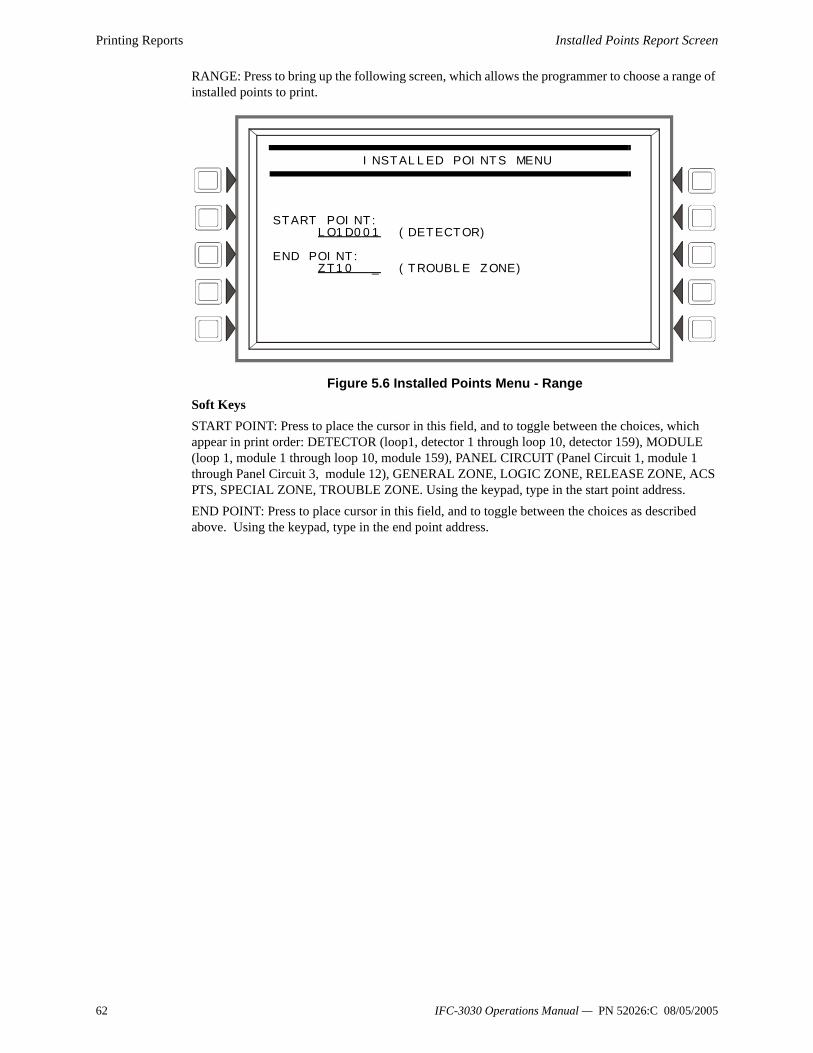
Printing Reports Installed Points Report Screen
RANGE: Press to bring up the following screen, which allows the programmer to choose a range of installed points to print.
Figure 5.6 Installed Points Menu - RangeSoft KeysSTART POINT: Press to place the cursor in this field, and to toggle between the choices, which appear in print order: DETECTOR (loop1, detector 1 through loop 10, detector 159), MODULE (loop 1, module 1 through loop 10, module 159), PANEL CIRCUIT (Panel Circuit 1, module 1 through Panel Circuit 3, module 12), GENERAL ZONE, LOGIC ZONE, RELEASE ZONE, ACS PTS, SPECIAL ZONE, TROUBLE ZONE. Using the keypad, type in the start point address.END POINT: Press to place cursor in this field, and to toggle between the choices as described above. Using the keypad, type in the end point address.
INSTALLED POINTS MENU
START POINT:
LO1D001 (DETECTOR)
END POINT:ZT10 _ (TROUBLE ZONE)
62 IFC-3030 Operations Manual — PN 52026:C 08/05/2005

Software Type ID Codes
Appendix A Software Type ID CodesAlphabetical ListThe following chart lists IFC-3030 Type ID codes in alphabetical order. These codes are assigned during programming based on the types and functions of the devices they are assigned. The codes appear in point message formats.
Software Type ID Code DeviceABORT SWITCH Monitor that provides an abort function for a releasing zone through connection to a UL-listed
abort station)
ACCESS MONTR Monitor for building access
ACK SWITCH Monitor used to silence panel sounder, and to give an acknowledge message on the panel display
AIR REF 7351J detector used to monitor air quality entering a protected area
ALARMS PEND Control module/panel circuit or NAC for output that will activate upon receipt of an alarm condition, and remain in the alarm state until all alarms have been acknowledged. Programmed for switch inhibit
ALLCALL PAGE Monitor used for emulation of AMG-1 All-call switch, activating all speaker circuits
AREA MONITOR Monitor for building access
AUDIBLE CKT Control module/panel circuit relay used on audible circuit NAC
AUDIO SYSTEM Monitor for audio equipment
BELL CIRCUIT Control module used with NAC with bells
blank Operates as CONTROL with no Type ID label
CONTROL Control module used with NAC
CONTROL NAC Control module/ Panel circuit relay or NAC
DRILL SWITCH Monitor used for activation that emulates panel Drill switch, activating silenceable fire outputs
EQUIP MONITR Monitor used for recording access to equipment
EVACUATE SWITCH Monitor used for activation that emulates panel Drill switch, activating silenceable fire outputs
FIRE CONTROL Monitors non-fire activations
FORM C RESET Control module used to interrupt 24V power to four-wire conventional detectors for 30 seconds upon reset. Used in conjunction with a monitor module with a conventional detector Type ID
GEN ALARM Control module, XPC-8 circuit, or XP5-C (NAC mode) configured as a Municipal Box Transmitter for NFPA 72 Auxiliary Fire Alarm Systems applications (MBT-1 required). This Type ID can also be used for general alarm activation. It is programmed as “switch inhibit”.
GEN PEND Control module, XPC-8 circuit, or XP5-C (NAC mode) that will activate upon receipt of an alarm and/or trouble condition, and remain in the ON state until all events have been acknowledged
GEN SUPERVIS Control module, XPC-8, or XP5-C (NAC mode) activated under any supervisory condition (includes sprinkler type). It is programmed as “switch inhibit”
GEN TROUBLE Control module, XPC-8, or XP5-C (NAC mode) activated under any System Trouble condition. It is programmed as “switch inhibit”
HEAT Adjustable threshold heat detector
HEAT+ Adjustable threshold heat detector with a low temperature warning.
HEAT(FIXED) Intelligent 135ºF thermal sensor detector
HEAT(ROR) 15ºF per minute rate-of-rise detector
HEAT DETECT Monitor for conventional heat detector
HORN CIRCUIT Control module/panel circuit relay module used with NAC with horns
INST RELEASE Control module used with NAC. Always non-silenceable and switch-inhibited
ISOLATED NAC Supervised NAC for notification appliance, used with audio isolators. Activates even if there is a short on its NAC circuit. Canada installations only.
ISOLATED SPK Supervised NAC for speaker circuit, used with audio isolators. Activates even if there is a short on its audio circuit. Canada installations only.
LATCH SUPERV Indicates latching supervisory condition
MAN RELEASE Monitor module that provides manual release for a releasing zone through connection to a UL-listed pull station
MAN REL DELAY Monitor module that provides manual release with a 10 second delay for a releasing zone through connection to a UL-listed pull station
MONITOR Alarm-monitoring device
NC MONITOR Alarm monitoring device, where an open circuit=active. SLC onlyNC NON FIRE Monitors non-fire activations, where an open circuit=active. SLC only.
Appendix Table A-1 Software Type ID Codes, Alphabetical List (1 of 3)
IFC-3030 Operations Manual — PN 52026:C 08/05/2005 63

Software Type ID Codes
NC SUP L Indicates latching supervisory conditon, where an open circuit=active. SLC only.
NC SUP T Indicates tracking supervisory conditon, where an open circuit=active. SLC onlyNON FIRE Monitors non fire activations
NONRESET CTL Output unaffected by “System Reset” command
PAS INHIBIT Monitor used to inhibit Positive Alarm Sequence (PAS)
POWER MONITR Monitor for main and auxiliary power supplies
PULL STATION Manual fire-alarm activating device
REL AUDIBLE Activates audio or visual devices steady when releasing starts
REL END BELL Control module used to activate NAC audio or visual device when releasing circuits shut off
REL CKT ULC Control module used to direct outputs to perform a release function as required by ULC
RELAY Form-C relay control module
REL. FORM C Form-C relay that directs outputs to perform a releasing function
RELEASE CKT Directs outputs to perform a releasing function
RESET SWITCH Monitor used to reset the control panel
RF MON MODUL Wireless alarm-monitoring device
RF PULL STA Wireless manual fire alarm-activating device
RFSMOKE(PHOTO) Wireless smoke detector
RF SUPERVSRY Wireless supervisory-monitoring device
SECOND SHOT Monitor module that provides a second manual release for a releasing zone through connection to a UL-listed pull station
SECURITY L Monitor for activation of latching security alarm
SIL SWITCH Monitor used as Signal Silence switch, turning off all activated silenceable outputs
SMOKE ACCLIM Combination photoelectric/heat detector
SMOKE(ACCLIM+) Combination photoelectric/heat detector with low temperature warning
SMOKE CONVEN Conventional smoke detector attached to an M302MJ
SMOKE DETECT Conventional smoke detector attached to an M302MJ
SMOKE(DUCTI) Duct ionization smoke detector
SMOKE(DUCTP) Duct photoelectric smoke detector
SMOKE(HARSH) HARSH smoke detector
SMOKE(ION) Ionization smoke detector
SMOKE(LASER) Laser smoke detector
SMOKE(MULTI) Multisensor smoke detector
SMOKE(PHOTO) Photoelectric smoke detector
SPEAKER Control module for speaker
SPRINKLR SYS Monitor for a waterflow device
STROBE Control module used with NAC with strobes
SUP L(DUCTI) Duct ionization smoke detector, latching
SUP L(DUCTP) Photoelectric smoke detector used as a duct detector to report supervisory condition rather than alarm, latching
SUP L(ION)** Ionization smoke detector, latching
SUP L(LASER)** Laser smoke detector, latching
SUP L(PHOTO)** Photoelectric smoke detector, latching
SUP T(DUCTI)*, ** Duct ionization smoke detector, tracking
SUP T(DUCTP)*, ** Photoelectric smoke detector used as a duct detector to report supervisory condition rather than alarm, tracking
SUP T(ION)*, ** Ionization smoke detector, tracking
SUP T(LASER)*, ** Laser smoke detector, tracking
SUP T(PHOTO)*, ** Photoelectric smoke detector, tracking
SYS MONITOR Monitor for equipment security
TAMPER Monitor for activation of tamper switch
TELE PAGE Monitor used to emulate the page button on an FFT-7, allowing remote paging to a fire area
TELEPHONE Control module for standard telephone circuit
TRACKING SUPERV Monitor for waterflow tamper switches for alarm points
TROUBLE MON Monitor for trouble inputs
WATERFLOW Monitor for waterflow alarm switch
Software Type ID Code Device
Appendix Table A-1 Software Type ID Codes, Alphabetical List (2 of 3)
64 IFC-3030 Operations Manual — PN 52026:C 08/05/2005
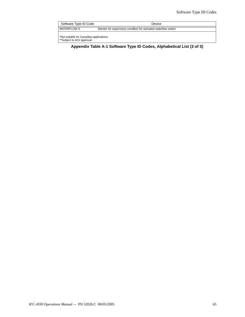
Software Type ID Codes
WATERFLOW S Monitor for supervisory condition for activated waterflow switch
*Not suitable for Canadian applications.**Subject to AHJ approval.
Software Type ID Code Device
Appendix Table A-1 Software Type ID Codes, Alphabetical List (3 of 3)
IFC-3030 Operations Manual — PN 52026:C 08/05/2005 65

Software Type ID Codes
66 IFC-3030 Operations Manual — PN 52026:C 08/05/2005
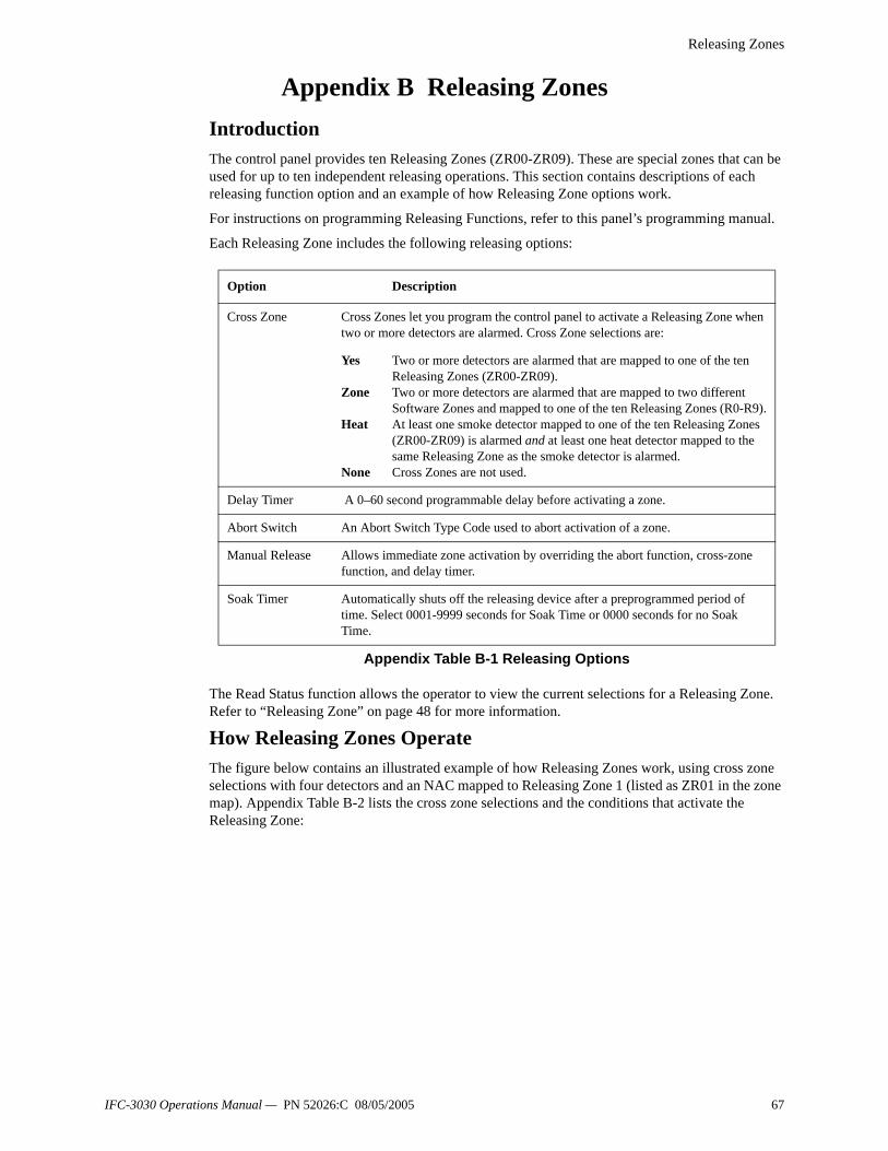
Releasing Zones
Appendix B Releasing ZonesIntroductionThe control panel provides ten Releasing Zones (ZR00-ZR09). These are special zones that can be used for up to ten independent releasing operations. This section contains descriptions of each releasing function option and an example of how Releasing Zone options work.
For instructions on programming Releasing Functions, refer to this panel’s programming manual.
Each Releasing Zone includes the following releasing options:
The Read Status function allows the operator to view the current selections for a Releasing Zone. Refer to “Releasing Zone” on page 48 for more information.
How Releasing Zones OperateThe figure below contains an illustrated example of how Releasing Zones work, using cross zone selections with four detectors and an NAC mapped to Releasing Zone 1 (listed as ZR01 in the zone map). Appendix Table B-2 lists the cross zone selections and the conditions that activate the Releasing Zone:
Option Description
Cross Zone Cross Zones let you program the control panel to activate a Releasing Zone when two or more detectors are alarmed. Cross Zone selections are:
Yes
Zone
Heat
None
Two or more detectors are alarmed that are mapped to one of the ten Releasing Zones (ZR00-ZR09).Two or more detectors are alarmed that are mapped to two different Software Zones and mapped to one of the ten Releasing Zones (R0-R9).At least one smoke detector mapped to one of the ten Releasing Zones (ZR00-ZR09) is alarmed and at least one heat detector mapped to the same Releasing Zone as the smoke detector is alarmed.Cross Zones are not used.
Delay Timer A 0–60 second programmable delay before activating a zone.
Abort Switch An Abort Switch Type Code used to abort activation of a zone.
Manual Release Allows immediate zone activation by overriding the abort function, cross-zone function, and delay timer.
Soak Timer Automatically shuts off the releasing device after a preprogrammed period of time. Select 0001-9999 seconds for Soak Time or 0000 seconds for no Soak Time.
Appendix Table B-1 Releasing Options
IFC-3030 Operations Manual — PN 52026:C 08/05/2005 67

Releasing Zones
Appendix Figure B-1 Illustrated Example of Cross Zone Programming
Listing of each Cross Zone option and the conditions required to activate the Releasing Zone, according to the example shown in Appendix Figure B-1.
Releasing Zone ZR01
General Zone Z002
General Zone Z001
Smoke Detector L02D101
Smoke Detector L02D103
Heat Detector L02D104
Smoke Detector L02D102
SLC NAC
Zone map = Z002 ZR1
Zone map = Z001 ZR01Zone map = Z001 ZR01
INPUTS ZONE MAPL02D101 Smoke Detector Z001, ZR01L02D102 Smoke Detector Z001, ZR01L02D103 Smoke Detector Z002, ZR01L02D104 Heat Detector Z002, ZR01
OUTPUTSLC Module Releasing Circuit ZR01
68 IFC-3030 Operations Manual — PN 52026:C 08/05/2005

Releasing Zones
.
Cross Zone Selection (Cross=) Condition(s) Required to Activate the Releasing zone
Cross=NONE An alarm from any detector activates the releasing circuit.
Cross=YES An alarm from any two detectors activates the releasing circuit.
Cross=ZONE An alarm from two detectors mapped to different Software Zones, but mapped to the same Releasing Zone. • An alarm from L02D101 and L02D103 – detectors mapped to
different zones, but both list ZR01 in their zone map.
• An alarm from L02D102 and L02D104 – detectors mapped to different zones, but both list ZR01 in their zone map.
• An alarm from L02D101 and L02D104 – detectors mapped to different zones, but both list ZR01 in their zone map.
• An alarm from L02D102 and L02D103 – detectors mapped to different zones, but both list ZR01 in their zone map.
Cross=HEAT Activation of heat detector L02D104 and one smoke detector (L02D101, L02D102, or L02D103).
Appendix Table B-2 Example of Cross Zone Selections
IFC-3030 Operations Manual — PN 52026:C 08/05/2005 69

Releasing Zones
70 IFC-3030 Operations Manual — PN 52026:C 08/05/2005
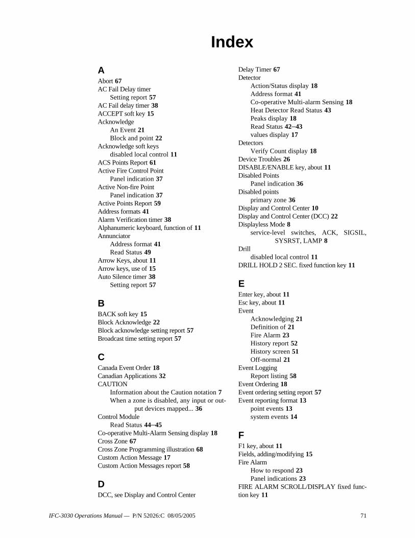
IndexAAbort 67AC Fail Delay timer
Setting report 57AC Fail delay timer 38ACCEPT soft key 15Acknowledge
An Event 21Block and point 22
Acknowledge soft keysdisabled local control 11
ACS Points Report 61Active Fire Control Point
Panel indication 37Active Non-fire Point
Panel indication 37Active Points Report 59Address formats 41Alarm Verification timer 38Alphanumeric keyboard, function of 11Annunciator
Address format 41Read Status 49
Arrow Keys, about 11Arrow keys, use of 15Auto Silence timer 38
Setting report 57
BBACK soft key 15Block Acknowledge 22Block acknowledge setting report 57Broadcast time setting report 57
CCanada Event Order 18Canadian Applications 32CAUTION
Information about the Caution notation 7When a zone is disabled, any input or out-
put devices mapped... 36Control Module
Read Status 44–45Co-operative Multi-Alarm Sensing display 18Cross Zone 67Cross Zone Programming illustration 68Custom Action Message 17Custom Action Messages report 58
DDCC, see Display and Control Center
Delay Timer 67Detector
Action/Status display 18Address format 41Co-operative Multi-alarm Sensing 18Heat Detector Read Status 43Peaks display 18Read Status 42–43values display 17
DetectorsVerify Count display 18
Device Troubles 26DISABLE/ENABLE key, about 11Disabled Points
Panel indication 36Disabled points
primary zone 36Display and Control Center 10Display and Control Center (DCC) 22Displayless Mode 8
service-level switches, ACK, SIGSIL,SYSRST, LAMP 8
Drilldisabled local control 11
DRILL HOLD 2 SEC. fixed function key 11
EEnter key, about 11Esc key, about 11Event
Acknowledging 21Definition of 21Fire Alarm 23History report 52History screen 51Off-normal 21
Event LoggingReport listing 58
Event Ordering 18Event ordering setting report 57Event reporting format 13
point events 13system events 14
FF1 key, about 11Fields, adding/modifying 15Fire Alarm
How to respond 23Panel indications 23
FIRE ALARM SCROLL/DISPLAY fixed func-tion key 11
IFC-3030 Operations Manual — P/N 52026:C 08/05/2005 71
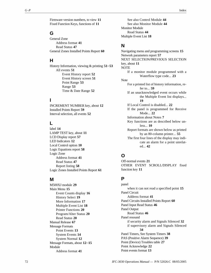
G–P Index
Firmware version numbers, to view 11Fixed Function Keys, functions of 11
GGeneral Zone
Address format 41Read Status 47
General Zones Installed Points Report 60
HHistory Information, viewing & printing 51–53
All events 51Event History report 52Event History screen 51Point Range 53Range 53Time & Date Range 52
IINCREMENT NUMBER key, about 12Installed Points Report 59Interval selection, all events 52
Llabel 14LAMP TEST key, about 11LCD Display report 57LED Indicators 12Local Control option 10Logic Equations report 58Logic Zone
Address format 41Read Status 47Report listing 58
Logic Zones Installed Points Report 61
MM500XJ module 29Main Menu 15
Event Counts display 16History Select 19More Information 17Multiple Event List 18Printer Functions 20Program/Alter Status 20Read Status 20
Manual Release 67Message Formats
Point Events 13System Events 14System Normal 12
Message Formats, about 12–15Module
Address format 41
See also Control Module 44See also Monitor Module 44
Monitor ModuleRead Status 44
Multiple Event List 18
NNavigating menu and programming screens 15Network parameters report 57NEXT SELECTION/PREVIOUS SELECTIONkey, about 11NOTE
If a monitor module programmed with aWaterflow type code... 23
NoteFor a printed list of history information, re-
fer to... 59If an unacknowledged event occurs while
the Multiple Event list displays...19
If Local Control is disabled... 22If the panel is programmed for Receive
Mode... 22Information about Notes 7Key functions are as described below un-
less... 10Report formats are shown below as printed
by an 80-column printer... 55The first four lines of the display may indi-
cate an alarm for a point unrelat-ed... 42
OOff-normal events 21OTHER EVENT SCROLL/DISPLAY fixedfunction key 11
Ppanel
when it can not read a specified point 15Panel Circuit
Address format 41Panel Circuits Installed Points Report 60Panel Input Read Status 46Panel Output
Read Status 46Panel resound
if security alarm and Signals Silenced 32if supervisory alarm and Signals Silenced
34Panel Timers, See System Timers 38PAS (Positive Alarm Sequence) 39Point (Device) Troubles table 27Point Acknowledge 22Point events format 13
72 IFC-3030 Operations Manual — P/N 52026:C 08/05/2005

Index R–S
Point Range select, all events 53Point Trouble
How to respond 26Panel indication 25
Power supplysupervision setting report 58
Pre-alarmAction 30Alert 30How to respond 30latching 30non-latching 30Panel indications 30
Presignal 38How to respond 39Panel Indication 39
Primary ZoneDisabling 36
PrintProgramming Menu 56Programming Menu 2 58
PRINT SCREEN key, about 11Printer
supervision setting report 58Printer Functions screen 55Program/Alter Status 20Proprietary Reminder timer
Setting report 57
RRead Status 41–50
Annunciator 49Detector 42General Zone 47Heat Detector 43Logic Zone 47Monitor Module 44Panel Input 46Panel Output 46Releasing Zone 48Special Function Zone 48Trouble Zone 49
RECALL LAST ENTRY key, about 12Receive Mode 11, 22Releasing Zone
Abort Switch 67Address Format 41Cross Zone 67Delay Timer 67Manual Release 67Read Status 48Soak Timer 67
Releasing Zones (R0-R9) 67–69Releasing Zones Installed Points Report 61Remote Reminder timer
Setting report 57
ReportACS Points 61Custom Action Messages 58Event Logging 58Installed Points 59LCD display settings 57Logic Equations 58Network parameters 57Settings 57Supervision 58Timers 57
Reports 55Resound, see Panel Resound
SSecurity Alarm
How to respond 32Panel indications 32
SECURITY SCROLL/DISPLAY fixed functionkey 11SIGNAL SILENCE fixed function key 11Silence Inhibit timer 11, 38
Setting report 57SLC Installed Points Report 59Smoke Detector, See Detector 42Soak Timer 67Soft Keys, functions of 11Software Type ID Codes 63, 67Special Function Keys 11Special Function Zone
Address format 41Read Status 48ZF0 and Presignal 38
Special Function ZonesInstalled Points Report 61
Supervision report 58SUPERVISORY SCROLL/DISPLAY fixedfunction key 11Supervisory Signal (Active Supervisory)
How to respond 34Panel indication 34
Supplemental Information 7System (Panel) Timers
AC Fail 38AC Fail Delay 57Alarm Verification 38Auto Silence 38, 57Silence Inhibit 38, 57
System event format 14System Normal
Internal panel activity 21System Normal screen 12, 21
custom graphic 13System Reset
disabled local control 11if Silence Inhibit Timer is running 11
IFC-3030 Operations Manual — P/N 52026:C 08/05/2005 73

T–Z Index
silencing active outputs 11SYSTEM RESET fixed function key,
about 11System Trouble
How to respond 26Panel indication 25
System Troubles 28
TTime & Date Range selection, all events 52Timers - See System (Panel) Timers 57Trouble - See System or Point trouble 26TROUBLE SCROLL/DISPLAY fixed functionkey 11Trouble Zone
Address format 41Read Status 49
Trouble Zones Installed Points Report 61Type ID codes, see Software Type ID codes 63
UUSA Event Order 18
VVeriFire
entering custom graphic 13VeriFire™
Use with displayless mode 8
WWARNING
Information about the Warning notation 7
ZZFO, See Special Zone ZF0 38Zones
Address Formats 41Primary, disabling 36See also General Zone, Logic Zone, Trou-
ble Zone, Releasing Zone, SpecialFunction Zone
74 IFC-3030 Operations Manual — P/N 52026:C 08/05/2005

IFC-3030 Operations Manual — P/N 52026:C 08/05/2005 75

Controls Group507 E. Michigan StreetP.O. Box 423Milwaukee, WI 53201
www.johnsoncontrols.com
Release CPrinted in U.S.A.