Embed Size (px)
Citation preview

116-P-BS60/FEE 2005-06-13 1
Fire Alarm Control Panel BS-60
Operator's handbook Program version
P1-BS60-202E-0
Protecting life, environment and property…

BS-60 Operators handbook
116-P-BS60/FEE 2005-06-13 2 Autronica Fire and Security AS
Contents
Page
1. Control panel..................................................................................................4
2. Prewarning .....................................................................................................5 2.1 Indications on the control panel at “Prewarning” ..................................5 2.2 Actions to be taken at “Prewarning”:......................................................5
3. Fire alarm ......................................................................................................7 3.1 Indications on the control panel at “Fire alarm” .....................................7 3.2 Actions to be taken at “Fire alarm”:........................................................7
4. More alarms (Multiple alarms) ...................................................................9 4.1 Indications on the control panel at “More alarms”: ................................9 4.2 Actions to be taken at “More alarms”:....................................................9
5. Fault .............................................................................................................11 5.1 Indications on the control panel at “Fault”: ..........................................11 5.2 Actions to be taken at “Fault”:...............................................................11 5.3 Fault signal from internal buzzer at processor fault or fault with the internal 5V .........................................................................................................12
6. Menu ............................................................................................................13 6.1 Menu structure ......................................................................................13 6.2 Menu operation .....................................................................................15 6.3 “MAIN MENU”....................................................................................15
7. Out-/in-control ............................................................................................16 7.1 Disable ..................................................................................................16
7.1.1 Disablement of address ..................................................................17 7.1.2 Disablement of zone .........................................................................18 7.1.3 Disablement of Fire-Brigade/Fighters (BMA, BMF) ......................19 7.1.4 Disablement of sounder (AK-circuit) ...............................................19 7.1.5 Disablement of controls ....................................................................20
7.1.5.1 Disablement of zone controls...................................................21 7.1.5.2 Disablement of Control-1 ........................................................22 7.1.5.3 Disablement of Control-2 ........................................................22
7.2 Restore ..................................................................................................23 7.2.1 Restoring of address(es)....................................................................23 7.2.2 Restoring of zone ..............................................................................24 7.2.3 Restoring of Fire Brigade/Fighters (BMA/BMF) .........................24 7.2.4 Restoring of sounders .......................................................................25 7.2.5 Restoring of controls.........................................................................25
7.2.5.1 Restoring of zone control.........................................................25 7.2.5.2 Restoring of Control-1 .............................................................26 7.2.5.3 Restoring of Control-2 .............................................................26
7.3 Alarm delay...........................................................................................27
8. Test ...............................................................................................................29 8.1 Test Frontpanel / buzzer........................................................................29 8.2 Test BMA/BMF....................................................................................30 8.3 Test fault ...............................................................................................30 8.4 Test sounders ........................................................................................31
BS-60 Operators handbook
116-P-BS60/FEE 2005-06-13 3 Autronica Fire and Security AS
8.5 Test controls..........................................................................................31 8.5.1 Test zone-controls.............................................................................31 8.5.2 Test Control-1 ...................................................................................32 8.5.3 Test Control-2 ...................................................................................32
8.6 Test alarm..............................................................................................32
9. Show status ..................................................................................................33 9.1 Show status prewarning ........................................................................33 9.2 Show status fault ...................................................................................34 9.3 Show status disablements .....................................................................35 9.4 Show-status Stored-events ....................................................................37
10. System ......................................................................................................38 10.1 Sensitivity .............................................................................................38
10.1.1 Addresses .....................................................................................39 10.1.1.1 Single addresses .....................................................................39 10.1.1.2 Total .......................................................................................39
10.1.2 Beyond-limits.................................................................................40 10.2 Internal ..................................................................................................40
10.2.1 Program version .............................................................................41 10.2.2 Adjust-clock...................................................................................41 10.2.3 Show-clock ....................................................................................41
10.3 Configuration ........................................................................................42
11. Service ......................................................................................................42

BS-60 Operators handbook
116-P-BS60/FEE 2005-06-13 4 Autronica Fire and Security AS
1. Control panel The operating panel consists of a text display (information window), indication lamps, operation buttons and a number key-pad. With these controls and indication devices, the entire fire alarm system is controlled.
Fig. no. 1: BS-60 front panel with text display, indication lamps, operation buttons and a number key-pad.
MORE ALARMS When the black button is pressed, the current alarms in queue are shown in the text display.
SILENCE/RESOUND SOUNDERS When the red button is pressed, all alarm devices and the internal buzzer are switched off/on..
RESET When the green button is pressed, the whole system are reset.
MORE ALARMS Red lamp lights when more alarms are present.
FIRE Red lamps lights in alarm condition.
These three amber (yellow) lamps will have custom designed text:
FUNCTION DISABLED Amber (yellow) lamp lights when the system is partly disabled (isolated).
FAULT Amber (yellow) lamp lights for any fault. Pulsating light.
Buzzer The operating panel has a built-in buzzer which is activated when there is an alarm, prewarning or fault condition.
MAINS Green lamp lights in normal condition.
Indication devices: Operation keys:
SONEALARM
DISABLE
FIRE
Silence&ResoundSounders
RESETMORE
ALARMS
FUNCTIONUTKOBLETPREWARN.
FAUL MAIN
BS 60
1470
258M
369
Device(s) still in alarm Cond.
DEVICES (STILL) IN ALARM COND. Amber (yellow) lamp lights when a address is automatically disabled.
PREWARNING Amber (yellow) lamp lights with a pulsating light when a prewarning has occurred.
Text display: (Information window). This gives information about all the events in the system and is used to programme the control as well.
ZONE These lamps lights and show zones in alarm state.
ZONE These lamps lights and show disabled zones.
Number key-pad The number key-pad is used to do menu selections.

BS-60 Operators handbook
116-P-BS60/FEE 2005-06-13 5 Autronica Fire and Security AS
2. Prewarning
2.1 Indications on the control panel at “Prewarning” Example of text in the display:
FW 1, ZONE NO: 3 ADDRESS: 14 INVESTIGATE PREWARNING LOCATION
If there is a slowly developed fire, the PREWARNING lamp will light before the lamps in the fire sign light up. Threat the prewarning as a normal fire alarm.
2.2 Actions to be taken at “Prewarning”: A. Follow all precautions described in the local fire instructions step by step.
B. Open the control panel door.
C. Press “SOUNDER SILENCE”.
The built-in buzzer will be turned off, but emits a sound signal every fourth minute as long as the door is open. The PREWARNING indication lamp will now change to steady light.
D. Investigate the scene of fire and carry out the necessary actions.
E. Press “RESET”. The following text will appear in the display:
Actions
The amber (yellow) lamp lights with pulsating light when a prewarning has occurred.
The internal buzzer is activated.
Prewarning
Indications
SONEALARM
DISABLE
FIRE
Silence&ResoundSounders
RESETMORE
ALARMS
FUNCTIONUTKOBLETPREWARN.
FAUL MAIN
BS 60
1470
258M
369
Device(s) still in alarm Cond.

BS-60 Operators handbook
116-P-BS60/FEE 2005-06-13 6 Autronica Fire and Security AS
RESET PROCEDURE IN PROGRESS WAIT ..............................
This text will remain for 60 seconds. (The seconds are counted in the display with one point appearing for every second from 0 to 30 seconds, and then the following 30 seconds are counted down by the removal of one point every second from 30 to 0.)
The reset procedure is executed in this 60 second period. If everything is normal the following text will appear in the display: RESET OK NORMAL CONDITION F. Close the door

BS-60 Operators handbook
116-P-BS60/FEE 2005-06-13 7 Autronica Fire and Security AS
3. Fire alarm
3.1 Indications on the control panel at “Fire alarm” Example of text in the display:
AL 1, ZONE NO: 3 ADDRESS NO: 14
This text states that an alarm has been sounded from the detector with address no. 14 in zone no. 3. If there is a fire slowly developed, the PREWARNING lamp will light before the lamps in the fire sign light.
3.2 Actions to be taken at “Fire alarm”: A: Follow the precautions described in the local fire instruction step by step. When the scene of the fire is investigated and the necessary actions are carried out, the sounders may be switched off. B: Open the control panel door. C: Press SILENCE/RESOUND SOUNDERS All the alarm devices will be stopped, including the internal buzzer. (The panel buzzer will emit a sound signal every fourth minute as long as the door is open). If the key is pressed once again the alarm devices will start up again. See sec. 7.3 “Set alarm delay” for more information.
The red lamps light and show which zone is in an alarm state (the yellow lamps show disablements).
Actions
The red FIRE indication lamps lights with pulsating light.
The internal buzzer is activated.
All sounders connected to the fire alarm system are activated.
Fire alarm
Indications
SONEALARM
DISABLE
FIRE
Silence&ResoundSounders
RESETMORE
ALARMS
FUNCTIONUTKOBLETPREWARN.
FAUL MAIN
BS 60
1470
258M
369
Device(s) still in alarm Cond.
BS-60 Operators handbook
116-P-BS60/FEE 2005-06-13 8 Autronica Fire and Security AS
All the alarm sounder outputs from the control panel will be turned off when the operation key “SILENCE/RESOUND SOUNDERS” button is pressed the first time. However, the message to the Fire Brigade/Fighters (BMA-) is not turned off. D: FIRE lights with a steady light. See section 4 if the lamp MORE ALARMS lights. When the scene of the fire is investigated and the necessary actions are carried out, reset the fire alarm control panel to normal condition. E: Press “RESET” The following text will appear in the display:
RESET PROCEDURE IN PROGRESS WAIT..........................
This text will remain for 60 seconds. (The seconds are counted in the display with one point appearing for every second from 0 to 30 seconds, and then the following 30 seconds are counted down by the removal of one point every second from 30 to 0.) If everything is normal the following text will appear in the display:
RESET OK NORMAL CONDITION
F: Close the door Normal condition means that the door on the control panel is closed and only the MAINS lamp is lit. After resetting, an address may still be in an alarm state. This can be due to mechanical damage, water damage, presence of smoke still in the detector’s chamber or an technical fault. If there is any address in an alarm state after resetting, it will be automatically disabled and isolated from the rest of the system. The following text will appear in the display:
1 ALARM ADDRESS(ES) IS DISABLED CONTROL PANEL IN ABNORMAL CONDITION
Contact Autronica’s service department to repair any fault so that the detector(s) can return to normal condition.

BS-60 Operators handbook
116-P-BS60/FEE 2005-06-13 9 Autronica Fire and Security AS
4. More alarms (Multiple alarms)
4.1 Indications on the control panel at “More alarms”: The display then indicates the number of the first and last alarm together with the zone number and the detector address. When more alarms are registered the text in the display may appear as follows:
AL 1, ZONE NO: 3 ADDRESS NO: 14 AL 3, ZONE NO: 6 ADDRESS NO: 35
NOTE! The last alarm will appear in the lower line in the display.
4.2 Actions to be taken at “More alarms”: A: Follow the procedure as given in section 3 A - F. B: In order to find out which alarms are in between the first and the last alarm, press the operation key “MORE ALARMS”. The alarms in between will then appear in the lower line in the text display, one for each press on the key. The alarms will appear in order, i.e. alarm no 2 will appear with the first press on the key (alarm number one will always remain in the top line), alarm number three with the second press of the key, alarm number four with the third press etc.
SONEALARM
DISABLE
FIRE
Silence&ResoundSounders
RESETMORE
ALARMS
FUNCTIONUTKOBLETPREWARN.
FAUL MAIN
BS 60
1470
258M
369
Device(s) still in alarm Cond.
Actions
The red FIRE indication lamps lights with pulsating light.
The internal buzzer is activated.
All sounders connected to the fire alarm system are activated.
The red lamps light and show which zone is in an alarm state, (yellow lamps show disablements.
The red MORE ALARMS indication lamp light.
The upper line in the display indicates the first alarm. The lower line indicates the last alarm.
More alarms
Indications
BS-60 Operators handbook
116-P-BS60/FEE 2005-06-13 10 Autronica Fire and Security AS
When you have gone through all the alarms, the text will show that you have returned back to alarm number two and the built-in buzzer will emit a signal.

BS-60 Operators handbook
116-P-BS60/FEE 2005-06-13 11 Autronica Fire and Security AS
5. Fault
5.1 Indications on the control panel at “Fault”: If the main processor stops, the internal buzzer is activated. By fault condition a fault message appears in the display. For example:
FA 1, ZONE NO: 3 ADDRESS NO: 14
5.2 Actions to be taken at “Fault”: A: Open the door. B: Press “SILENCE/RESOUND SOUNDERS”. (The built-in buzzer emits a sound signal every fourth minute as long as the door is open). FAULT lights with a steady light. C: Press “RESET”. The following text will appear in the display:
RESET PROCEDURE IN PROGRESS WAIT ...
RESET OK NORMAL CONDITION
SONEALARM
UTKOBLET
BRANN
AVSTILL KLOKKER
TILBAKESTILLFLERE
ALARMER
DELER AV ANLEGGETUTKOBLETFORVARSEL
FEIL NETT
BS 60
SLOKKEANLEGGAKTIVERTBRANNVENTILASJONAKTIVERTBRANNVESENMOTTATT MELDING
ALARMSTED UTKOBLET
1470
258M
369
Actions
The amber (yellow) FAULT indication lamp lights with pulsating light.
The internal buzzer is activated.
The text display indicates the fault and location.
Fault
Indications
BS-60 Operators handbook
116-P-BS60/FEE 2005-06-13 12 Autronica Fire and Security AS
D: Close the door. E: If there is still a fault, contact Autronica’s service department to repair any fault so the control panel can return to normal operation.
5.3 Fault signal from internal buzzer at processor fault or fault with the internal 5V • Loss of internal 5V will give continuous signal in the internal buzzer.
• Processor fault will give pulsing- or continuous signal in the internal buzzer.
• At both fault types the display will be dark or the text will be locked.
Fault on processor or internal 5V

BS-60 Operators handbook
116-P-BS60/FEE 2005-06-13 13 Autronica Fire and Security AS
6. Menu
6.1 Menu structure The whole menu structure is shown here, but “CONFIGURATION” and “SERVICE” is described in the “Commissioning handbook” - BS-60. Select Main menu 1--Out/in- 1--Disable 1--Address control 2--Zone A) 3--Fire-Brigade 4--Sounders 5--Controls 1-- Zone-control 2 -- Control-1 2--Restore 1--Address 3 -- Control-2 2--Zone 3--Fire-Brigade 4--Sounders 5--Controls 1-- Zone-control 2 -- Control-1 3--Alarm delay 3 -- Control-2 2--Test 1--Frontpanel/buzzer 2--BMA, BMF 3--Fault 4--Sounders 5--Controls. 1--Zone-control 6--Alarm 2--Control-1 3--Control-2 3--Show- 1--Prewarning status 2--Fault E) 3--Disablements 4--Stored-events 4--System 1--Sensitivity 1--Addresses 1--Single addresses 2--Beyond limits 2--Total 2--Internal 1--Program-version E) 2--Adjust-clock E) 3--Show-clock D) 3--Config. 1--Data 2--Zone 1--Start no. 2--Edit 1--Insert 2--Delete 3--End 3--Automatic B) 4--Save 3--Renumber 4--Delete 5--Service 1--Alarm-test 5--End 2--Custom-text 3--Watchdog-counter
Menu
Menu structure
C)

BS-60 Operators handbook
116-P-BS60/FEE 2005-06-13 14 Autronica Fire and Security AS
REMARKS A) - E) IN ABOVE MENU STRUCTURE A) The “DISABLE SOUNDERS” function is password protected for the English
version..
B) The “SAVE” function is always password protected (special requirements are set to OFF, SOLAS or LPC).
C) The “SERVICE” function is always password protected (special requirements are set to “OFF”, SOLAS or LPC.) The “SERVICE” function is described in the “Commissioning handbook” - BS-60.
D) The DIP-switch 18.7 has to be in position “OFF” to reach the “CONFIGURATION” function. The “CONFIGURATION” function is described in the “Commissioning handbook” - BS-60.
E) The DIP-switch 18.7 has to be in position “ON” to reach the “STORED-EVENTS”, “CUSTOM-TEXT”, “ADJUST-CLOCK” and “SHOW-CLOCK” functions.

BS-60 Operators handbook
116-P-BS60/FEE 2005-06-13 15 Autronica Fire and Security AS
6.2 Menu operation All information given in this section is closely related to the MENU structure given in section 6.1. Please confer this structure when reading the following information. By pressing the ”MENU” key, the system always returns to the main menu. Values which are used are default values from the factory. All values can be changed by using the key-pad. Remember to save the values before closing the door.
6.3 “MAIN MENU” When the control panel door is opened, the following text will appear in the display:
AUTRONICA FIRE ALARM SYSTEM BS-60 USERS MENU
When the alarm delay is activated, the following text will appear in the display: (See section 7.3).
ALARM DELAY H.MM HOUR(S)
H - Hours MM - Minutes By pressing the “MENU” key, the following text will appear in the display:
MAIN MENU: 1:OUT/IN-CONTROL 2:TEST 3: SHOW-STATUS 4:SYSTEM 5:SERVICE
Operation
Main menu

BS-60 Operators handbook
116-P-BS60/FEE 2005-06-13 16 Autronica Fire and Security AS
7. Out-/in-control MAIN MENU Out/in-control Disable Address Zone Fire-Brigade Sounders Controls Zone-control Control-1 Restore Address Control-2 Zone Fire-Brigade Sounders Controls Zone-cotnrol Control-1 Alarm delay Control-2 Select “OUT/IN-CONTROL” function by pressing “1” in the “MAIN MENU”. The following text will appear in the display:
OUT/IN-CONTROL 1:DISABLE 2:RESTORE 3:SET ALARM DELAY
7.1 Disable When disabling parts of the system, the amber (yellow) lamp “FUNCTION DISABLED” on the front of the control panel will light as long as the disabling lasts. The maximum disable time is 98 hours. By selecting disable time of 99 hours, the function will be disabled for ever. Select “DISABLE” function by pressing “1” in the “OUT/IN-CONTROL”-menu. The following text will appear in the display:
DISABLE : 1:ADDRESS 2:ZONE 3:FIRE-BRIGADE 4:SOUNDERS 5:CONTROLS
To reach this function rapidly, press “1” when the front door is opened. For the LPC program version the internal buzzer will be activated approx. every 5 sec. while some parts are disabled.
Out-/in-control
Disable
BS-60 Operators handbook
116-P-BS60/FEE 2005-06-13 17 Autronica Fire and Security AS
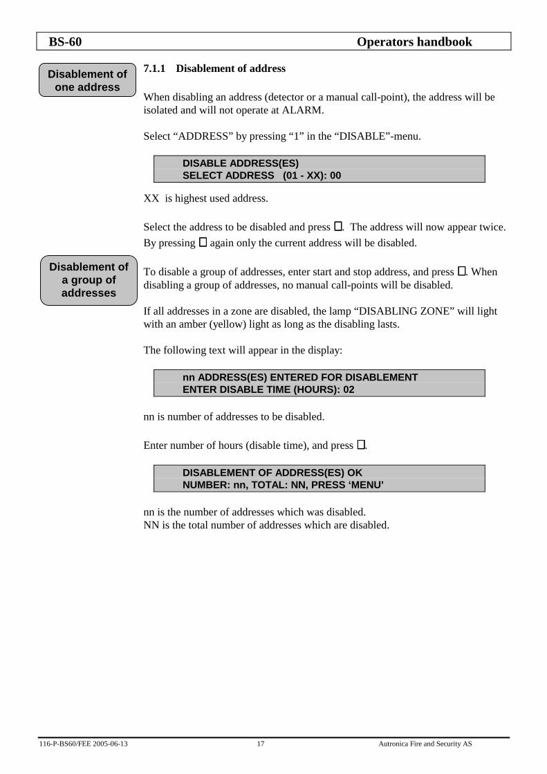
7.1.1 Disablement of address When disabling an address (detector or a manual call-point), the address will be isolated and will not operate at ALARM. Select “ADDRESS” by pressing “1” in the “DISABLE”-menu.
DISABLE ADDRESS(ES) SELECT ADDRESS (01 - XX): 00
XX is highest used address. Select the address to be disabled and press ↵↵↵↵ . The address will now appear twice. By pressing ↵ ↵ ↵ ↵ again only the current address will be disabled. To disable a group of addresses, enter start and stop address, and press ↵↵↵↵ . When disabling a group of addresses, no manual call-points will be disabled. If all addresses in a zone are disabled, the lamp “DISABLING ZONE” will light with an amber (yellow) light as long as the disabling lasts. The following text will appear in the display:
nn ADDRESS(ES) ENTERED FOR DISABLEMENT ENTER DISABLE TIME (HOURS): 02
nn is number of addresses to be disabled. Enter number of hours (disable time), and press ↵↵↵↵ .
DISABLEMENT OF ADDRESS(ES) OK NUMBER: nn, TOTAL: NN, PRESS ‘MENU’
nn is the number of addresses which was disabled. NN is the total number of addresses which are disabled.
Disablement of one address
Disablement of a group of addresses

BS-60 Operators handbook
116-P-BS60/FEE 2005-06-13 18 Autronica Fire and Security AS
7.1.2 Disablement of zone When disabling zone(s), the zone(s) will be isolated and will not operate at alarm, unless a manual call-point is activated. The lamp “ZONE DISABLED” in addition to the lamp “FUNCTION DISABLED” will light with a amber (yellow) light as long as the disabling lasts. Select “ZONE” by pressing “2” in the “DISABLE”-menu. The following text will appear in the display:
DISABLE ZONE SELECT ZONE-NUMBER: 000
Select the zone to be disabled and press ↵↵↵↵ . The following text will appear in the display:
DISABLEMENT OF ZONE NO: YYY ENTER DISABLE TIME (HOURS): 02
YYY is the selected zone to be disabled.
Enter the number of hours (disable time) and press ↵↵↵↵ . The following text will appear in the display:
DISABLEMENT OF ZONE NO: YYY OK PRESS ‘MENU’
YYY is the disabled zone. If an unused zone number is selected, the following text will appear in the display:
ACCESS OF ZONE: YYY IS BLOCKED PRESS ‘MENU’
YYY is the selected zone to be disabled.
Disablement of zone
BS-60 Operators handbook
116-P-BS60/FEE 2005-06-13 19 Autronica Fire and Security AS
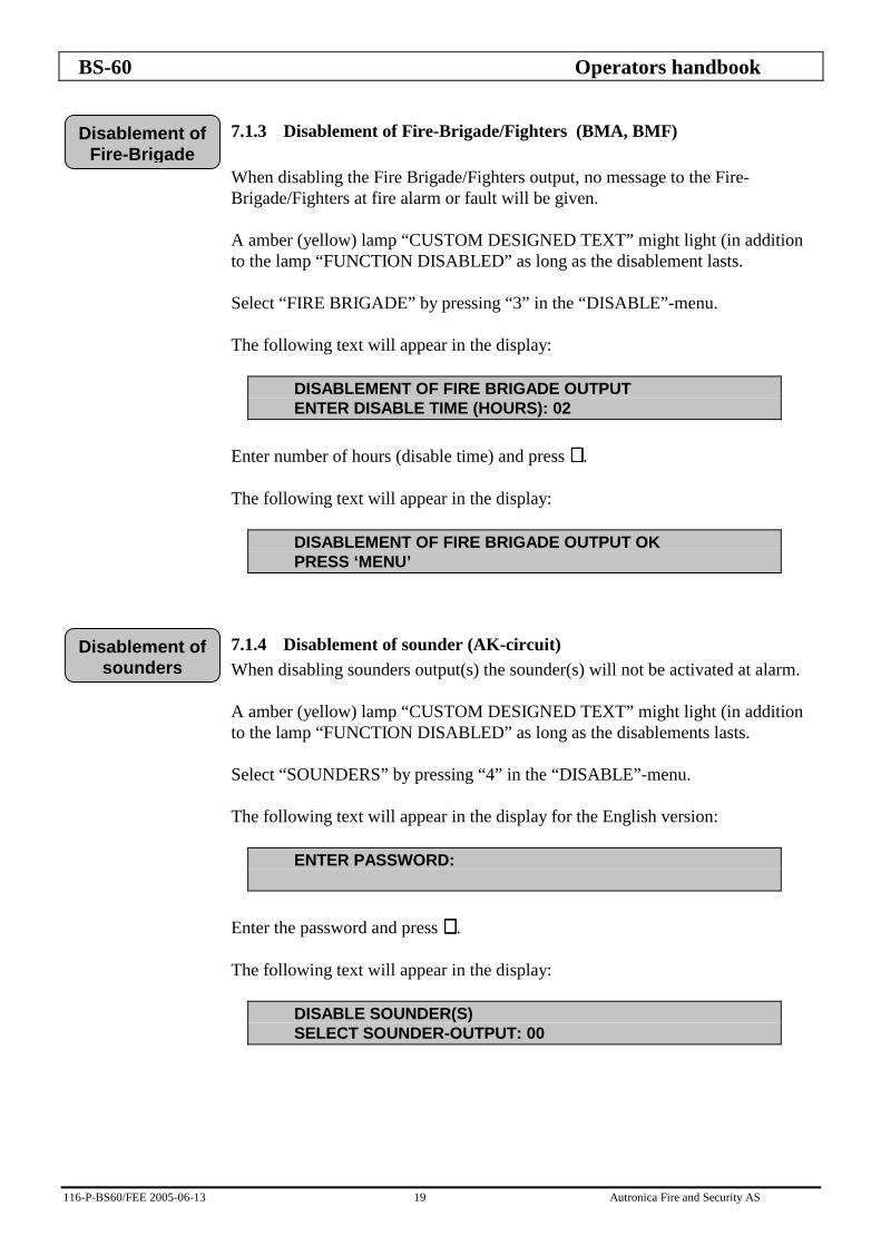
7.1.3 Disablement of Fire-Brigade/Fighters (BMA, BMF) When disabling the Fire Brigade/Fighters output, no message to the Fire-Brigade/Fighters at fire alarm or fault will be given. A amber (yellow) lamp “CUSTOM DESIGNED TEXT” might light (in addition to the lamp “FUNCTION DISABLED” as long as the disablement lasts. Select “FIRE BRIGADE” by pressing “3” in the “DISABLE”-menu. The following text will appear in the display:
DISABLEMENT OF FIRE BRIGADE OUTPUT ENTER DISABLE TIME (HOURS): 02
Enter number of hours (disable time) and press ↵↵↵↵ . The following text will appear in the display:
DISABLEMENT OF FIRE BRIGADE OUTPUT OK PRESS ‘MENU’
7.1.4 Disablement of sounder (AK-circuit) When disabling sounders output(s) the sounder(s) will not be activated at alarm. A amber (yellow) lamp “CUSTOM DESIGNED TEXT” might light (in addition to the lamp “FUNCTION DISABLED” as long as the disablements lasts. Select “SOUNDERS” by pressing “4” in the “DISABLE”-menu. The following text will appear in the display for the English version:
ENTER PASSWORD:
Enter the password and press ↵↵↵↵ . The following text will appear in the display:
DISABLE SOUNDER(S) SELECT SOUNDER-OUTPUT: 00
Disablement of Fire-Brigade
Disablement of sounders

BS-60 Operators handbook
116-P-BS60/FEE 2005-06-13 20 Autronica Fire and Security AS
By pressing ↵ ↵ ↵ ↵ at sounder-output 00, all sounder-outputs will be selected for disablement, and the following text will appear in the display:
DISABLEMENT OF ALL SOUNDER-OUTPUTS ENTER DISABLE TIME (HOURS): 02
Enter number of hours (disable time) and press ↵↵↵↵ . The following text will appear in the display:
DISABLEMENT OF 4 SOUNDER-OUTPUTS OK PRESS ‘MENU’
To disable one sounder-output, select the sounder-output to be disabled, and press ↵↵↵↵ . The following text will appear in the display:
DISABLEMENT OF SOUNDER-OUTPUT: PP ENTER DISABLE TIME (HOURS): 02
PP is the selected sounder-output to be disabled. Enter number of hours (disable time) and press ↵↵↵↵ . The following text will appear in the display:
DISABLEMENT OF SOUNDER-OUTPUT: PP OK PRESS ‘MENU’
PP is disabled sounder-output.
7.1.5 Disablement of controls Select “CONTROLS” by pressing “5” in the “DISABLE”-menu. The following text will appear in the display:
DISABLE CONTROLS: 1:ZONE-CONTR. 2:CONTROL-1 3:CONTROL-2
Disablement of all sounder
Disablement of controls
Disablement of sounders
one by one

BS-60 Operators handbook
116-P-BS60/FEE 2005-06-13 21 Autronica Fire and Security AS
7.1.5.1 Disablement of zone controls When disabling the zone-control(s), the zone-control(s) will not be activated at alarm in the connected zone. Select “ZONE-CONTR.” by pressing “1” in the “DISABLE CONTROLS”-menu, and the following text will appear in the display:
DISABLE ZONE-CONTROL(S) SELECT ZONE-CONTROL: 000
By pressing ↵ ↵ ↵ ↵ at zone-control 000, all zone-controls will be selected for disablement, and the following text will appear in the display:
DISABLEMENT OF ALL ACTIVE ZONE-CONTROLS ENTER DISABLE TIME (HOURS): 02
Enter number of hours (disable time) and press ↵↵↵↵ . The following text will appear in the display:
DISABLEMENT OF NN ZONE-CONTROL(S) OK PRESS ‘MENU’
NN is the number of active zone-controls which is disabled. To disable one zone-control, select the zone-control to be disabled, and press ↵↵↵↵ . The following text will appear in the display:
DISABLEMENT OF ZONE-CONTROL: ZZZ ENTER DISABLE TIME (HOURS): 02
ZZZ is the selected zone-control to be disabled. Enter the number of hours (disable time) and press ↵↵↵↵ . The following text will appear in the display:
DISABLEMENT OF ZONE-CONTROL: ZZZ OK PRESS ‘MENU’
ZZZ is the number of disabled zone-controls. If an unused zone-control is selected, the following text will appear in the display:
ACCESS OF ZONE-CONTROL ZZZ IS BLOCKED PRESS ‘MENU’
ZZZ is the selected zone-control to be disabled.
Disablement of zone controls
Disablement of zone-controls
one by one

BS-60 Operators handbook
116-P-BS60/FEE 2005-06-13 22 Autronica Fire and Security AS
7.1.5.2 Disablement of Control-1 When disabling Control-1 output, the Control-1 will not be activated at alarm. Select “CONTROL-1” by pressing “2” in the “DISABLE CONTROLS”-menu, and the following text will appear in the display:
DISABLEMENT OF CONTROL-1 ENTER DISABLE TIME (HOURS): 02
Enter number of hours (disable time) and press ↵↵↵↵ . The following text will appear in the display:
DISABLEMENT OF CONTROL-1 OK PRESS ‘MENU’
7.1.5.3 Disablement of Control-2 When disabling Control-2 output, the Control-2 will not be activated at alarm or prewarning. Select “CONTROL-2” by pressing “3” in the ”DISABLE CONTROLS”-menu, and the following text will appear in the display:
DISABLEMENT OF CONTROL-2 ENTER DISABLE TIME (HOURS): 02
Enter number of hours (disable time) and press ↵↵↵↵ . The following text will appear in the display:
DISABLEMENT OF CONTROL-2 OK PRESS ‘MENU’
Disablement of Control-2
Disablement of Control-1
BS-60 Operators handbook
116-P-BS60/FEE 2005-06-13 23 Autronica Fire and Security AS
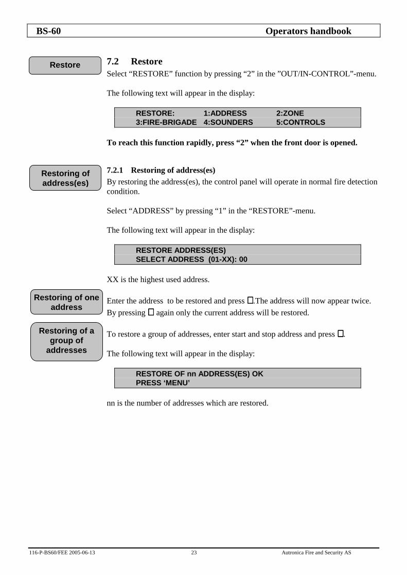
7.2 Restore Select “RESTORE” function by pressing “2” in the ”OUT/IN-CONTROL”-menu. The following text will appear in the display:
RESTORE: 1:ADDRESS 2:ZONE 3:FIRE-BRIGADE 4:SOUNDERS 5:CONTROLS
To reach this function rapidly, press “2” when the front door is opened.
7.2.1 Restoring of address(es) By restoring the address(es), the control panel will operate in normal fire detection condition. Select “ADDRESS” by pressing “1” in the “RESTORE”-menu. The following text will appear in the display:
RESTORE ADDRESS(ES) SELECT ADDRESS (01-XX): 00
XX is the highest used address. Enter the address to be restored and press ↵↵↵↵ .The address will now appear twice. By pressing ↵ ↵ ↵ ↵ again only the current address will be restored. To restore a group of addresses, enter start and stop address and press ↵↵↵↵ . The following text will appear in the display:
RESTORE OF nn ADDRESS(ES) OK PRESS ‘MENU’
nn is the number of addresses which are restored.
Restore
Restoring of address(es)
Restoring of one address
Restoring of a group of
addresses

BS-60 Operators handbook
116-P-BS60/FEE 2005-06-13 24 Autronica Fire and Security AS
7.2.2 Restoring of zone By restoring the zone, all related addresses will be restored and operate in normal fire detection condition. Select “ZONE” by pressing “2” in the “RESTORE”-menu. The following text will appear in the display:
RESTORE ZONE SELECT ZONE -NUMBER: 000
Select the zone-number to be restored and press ↵↵↵↵ . The following text will appear in the display:
RESTORE OF ZONE NO: YYY OK PRESS ‘MENU’
YYY is the restored zone. If an unused zone is selected, the following text will appear in the display:
ACCESS OF ZONE: YYY IS BLOCKED PRESS ‘MENU’
YYY is the selected zone.
7.2.3 Restoring of Fire Brigade/Fighters (BMA/BMF) By restoring the Fire Brigade/Fighters output, the output will operate in normal condition, and message to the Fire Brigade/Fighters at fire alarm and fault will be given. Select “FIRE BRIGADE” by pressing “3” in the “RESTORE”-menu. The following text will appear in the display:
RESTORE OF FIRE BRIGADE OUTPUT OK PRESS ‘MENU’
Restoring of zone
Restoring of Fire Brigade outputs

BS-60 Operators handbook
116-P-BS60/FEE 2005-06-13 25 Autronica Fire and Security AS
7.2.4 Restoring of sounders By restoring the sounder(s) the sounder(s) will operate in normal condition at fire alarm. Select “SOUNDERS” by pressing “4” in the “RESTORE”-menu. The following text will appear in the display:
RESTORE SOUNDER(S) SELECT SOUNDER-OUTPUT: 00
By pressing ↵↵↵↵ at sounder-output 00, all sounder-outputs will be restored, and the following text will appear in the display:
RESTORE OF 4 SOUNDER-OUTPUTS OK PRESS ‘MENU’
To restore one sounder-output, select the sounder-output to be restored, and press ↵↵↵↵ . The following text will appear in the display:
RESTORE OF SOUNDER-OUTPUT: PP OK PRESS ‘MENU’
PP is the selected and restored sounder-output.
7.2.5 Restoring of controls Select “CONTROLS” by pressing “5” in the “RESTORE”-menu. The following text will appear in the display:
RESTORE CONTROLS: 1:ZONE-CONTR. 2:CONTROL-1 3:CONTROL-2
7.2.5.1 Restoring of zone control By restoring the zone-control(s), zone-control(s) will operate in normal condition at fire alarm. Select “ZONE-CONTR.” by pressing “1” in the “RESTORE CONTROLS”-menu. The following text will appear in the display:
RESTORE ZONE-CONTROL(S) SELECT ZONE-CONTROL: 000
Restoring of zone control
Restoring of all zone-controls
Restoring of sounders
Restoring of controls
Restoring of all sounder outputs
Restoring of the sounders
one by one

BS-60 Operators handbook
116-P-BS60/FEE 2005-06-13 26 Autronica Fire and Security AS
By pressing ↵↵↵↵ at zone-control 000, all controls will be restored, and the following text will appear in the display:
RESTORE OF 16 ZONE-CONTROL(S) OK PRESS ‘MENU’
To restore one zone-control, select the zone-control to be restored and press ↵↵↵↵ . The following text will appear in the display:
RESTORE OF ZONE-CONTROL: ZZZ OK PRESS ‘MENU’
ZZZ is the selected zone-control. If an unused zone is selected, the following text will appear in the display:
ACCESS OF ZONE-CONTROL: ZZZ IS BLOCKED PRESS ‘MENU’
ZZZ is the selected zone-control.
7.2.5.2 Restoring of Control-1 By restoring the Control-1 output, the Control-1 will operate in normal condition at alarm. Select “CONTROL-1” by pressing “2” in the “RESTORE CONTROLS”-menu. The following text will appear in the display:
RESTORE OF CONTROL-1 OK PRESS ‘MENU’
7.2.5.3 Restoring of Control-2 By restoring the Control-2 output, the Control-2 will operate in normal condition at alarm or prewarning. Select “CONTROL-2” by pressing “3” in the “RESTORE CONTROLS”-menu. The following text will appear in the display:
RESTORE OF CONTROL-2 OK PRESS ‘MENU’
Restoring of Control-1
Restoring of Control-2
Restoring of zone-controls
one by one
BS-60 Operators handbook
116-P-BS60/FEE 2005-06-13 27 Autronica Fire and Security AS
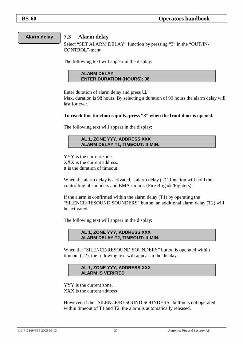
7.3 Alarm delay Select “SET ALARM DELAY” function by pressing “3” in the “OUT/IN-CONTROL”-menu. The following text will appear in the display:
ALARM DELAY ENTER DURATION (HOURS): 08
Enter duration of alarm delay and press ↵↵↵↵ . Max. duration is 98 hours. By selecting a duration of 99 hours the alarm delay will last for ever. To reach this function rapidly, press “3” when the front door is opened. The following text will appear in the display:
AL 1, ZONE YYY, ADDRESS XXX ALARM DELAY T1, TIMEOUT: tt MIN.
YYY is the current zone. XXX is the current address. tt is the duration of timeout. When the alarm delay is activated, a alarm delay (T1) function will hold the controlling of sounders and BMA-circuit. (Fire Brigade/Fighters). If the alarm is confirmed within the alarm delay (T1) by operating the “SILENCE/RESOUND SOUNDERS” button, an additional alarm delay (T2) will be activated. The following text will appear in the display:
AL 1, ZONE YYY, ADDRESS XXX ALARM DELAY T2, TIMEOUT: tt MIN.
When the “SILENCE/RESOUND SOUNDERS” button is operated within timeout (T2), the following text will appear in the display:
AL 1, ZONE YYY, ADDRESS XXX ALARM IS VERIFIED
YYY is the current zone. XXX is the current address However, if the “SILENCE/RESOUND SOUNDERS” button is not operated within timeout of T1 and T2, the alarm is automatically released.
Alarm delay

BS-60 Operators handbook
116-P-BS60/FEE 2005-06-13 28 Autronica Fire and Security AS
The second press on the “SILENCE/RESOUND SOUNDERS” button stops the activation of sounders - and BMA-circuit (Fire Brigade/Fighters). The third press on the “SILENCE/RESOUND SOUNDERS” button will resound the sounders - and BMA-circuits.

BS-60 Operators handbook
116-P-BS60/FEE 2005-06-13 29 Autronica Fire and Security AS
8. Test Main menu Test Frontpanel/buzzer BMA/BMF Fault Sounders Controls Zone-control Alarm Control-1 Control-2 All tests will be terminated by pressing “MENU” or closing the door. If a fire alarm occurs, the tests will be terminated, and the alarm messages will appear in the display. Select “TEST” function by pressing “2” in the “MAIN MENU”. The following text will appear in the display:
TEST 1:FRONTPANEL/BUZZER 2:BMA/BMF 3:FAULT 4:SOUNDERS 5:CONTOLS 6:ALARM
8.1 Test Frontpanel / buzzer Select “FRONTPANEL/BUZZER” by pressing “1” in the “TEST”-menu. The following text will appear in the display:
DISPLAY TEST:
All characters used in the display will appear, and all indication lamps on the control panel front will light. The internal buzzer will be activated approx. every 5. sec. To stop the test press “MENU”.
Test
Test frontpanel/ buzzer
BS-60 Operators handbook
116-P-BS60/FEE 2005-06-13 30 Autronica Fire and Security AS
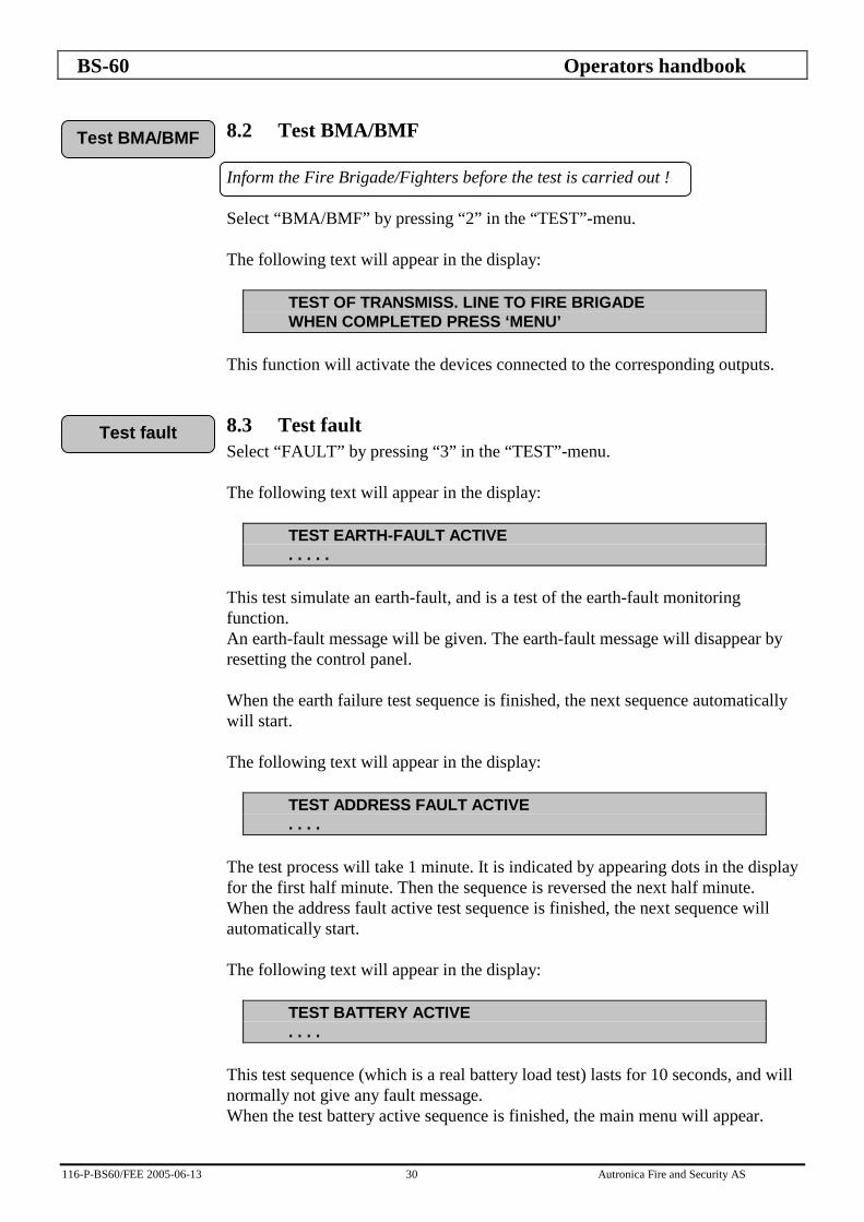
8.2 Test BMA/BMF Inform the Fire Brigade/Fighters before the test is carried out ! Select “BMA/BMF” by pressing “2” in the “TEST”-menu. The following text will appear in the display:
TEST OF TRANSMISS. LINE TO FIRE BRIGADE WHEN COMPLETED PRESS ‘MENU’
This function will activate the devices connected to the corresponding outputs.
8.3 Test fault Select “FAULT” by pressing “3” in the “TEST”-menu. The following text will appear in the display:
TEST EARTH-FAULT ACTIVE . . . . .
This test simulate an earth-fault, and is a test of the earth-fault monitoring function. An earth-fault message will be given. The earth-fault message will disappear by resetting the control panel. When the earth failure test sequence is finished, the next sequence automatically will start. The following text will appear in the display:
TEST ADDRESS FAULT ACTIVE . . . .
The test process will take 1 minute. It is indicated by appearing dots in the display for the first half minute. Then the sequence is reversed the next half minute. When the address fault active test sequence is finished, the next sequence will automatically start. The following text will appear in the display:
TEST BATTERY ACTIVE . . . .
This test sequence (which is a real battery load test) lasts for 10 seconds, and will normally not give any fault message. When the test battery active sequence is finished, the main menu will appear.
Test fault
Test BMA/BMF
BS-60 Operators handbook
116-P-BS60/FEE 2005-06-13 31 Autronica Fire and Security AS
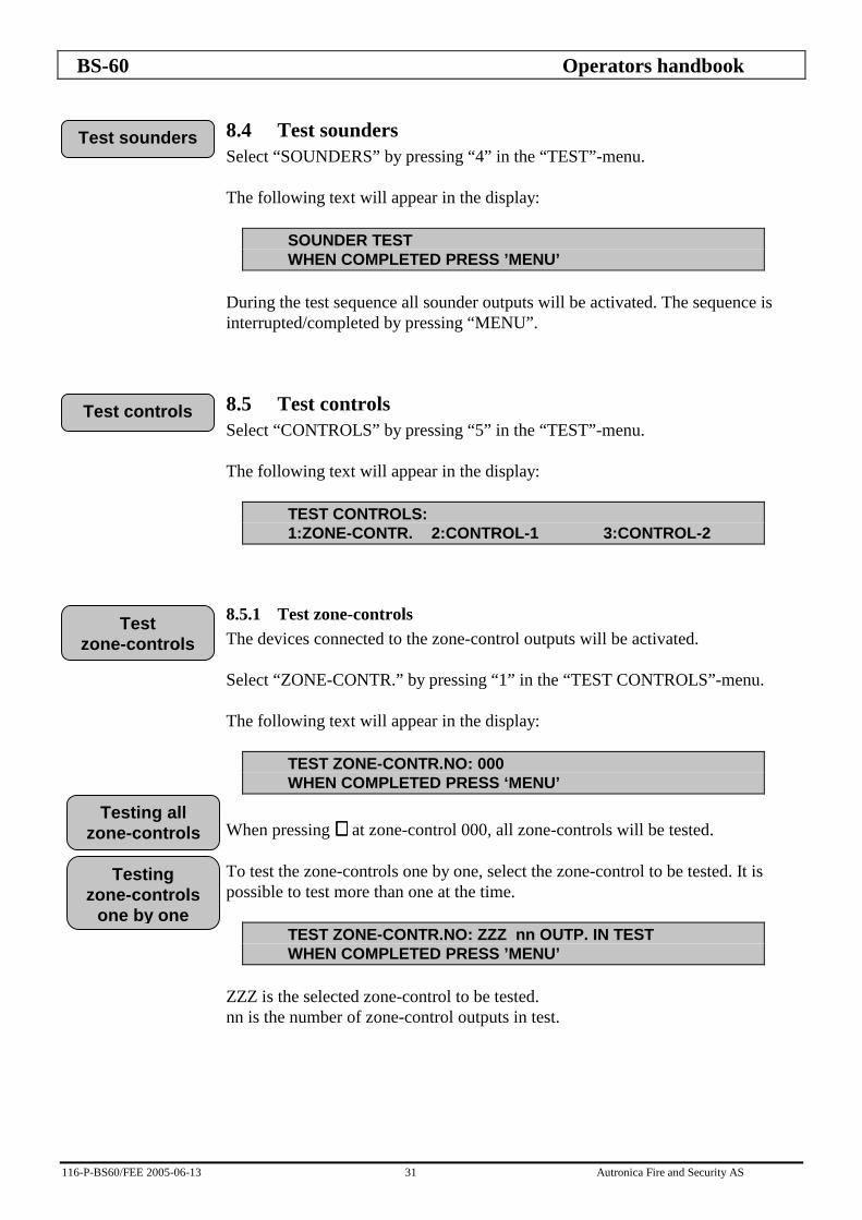
8.4 Test sounders Select “SOUNDERS” by pressing “4” in the “TEST”-menu. The following text will appear in the display:
SOUNDER TEST WHEN COMPLETED PRESS ’MENU’
During the test sequence all sounder outputs will be activated. The sequence is interrupted/completed by pressing “MENU”.
8.5 Test controls Select “CONTROLS” by pressing “5” in the “TEST”-menu. The following text will appear in the display:
TEST CONTROLS: 1:ZONE-CONTR. 2:CONTROL-1 3:CONTROL-2
8.5.1 Test zone-controls The devices connected to the zone-control outputs will be activated. Select “ZONE-CONTR.” by pressing “1” in the “TEST CONTROLS”-menu. The following text will appear in the display:
TEST ZONE-CONTR.NO: 000 WHEN COMPLETED PRESS ‘MENU’
When pressing ↵↵↵↵ at zone-control 000, all zone-controls will be tested. To test the zone-controls one by one, select the zone-control to be tested. It is possible to test more than one at the time.
TEST ZONE-CONTR.NO: ZZZ nn OUTP. IN TEST WHEN COMPLETED PRESS ’MENU’
ZZZ is the selected zone-control to be tested. nn is the number of zone-control outputs in test.
Test sounders
Test controls
Test zone-controls
Testing all zone-controls
Testing zone-controls
one by one

BS-60 Operators handbook
116-P-BS60/FEE 2005-06-13 32 Autronica Fire and Security AS
8.5.2 Test Control-1 Select “CONTROL-1” by pressing “2” in the “TEST CONTROLS”-menu. The following text will appear in the display:
TEST OF CONTROL-1 WHEN COMPLETED PRESS ‘MENU’
The device connected to the Control-1 output will be activated.
8.5.3 Test Control-2 Select “CONTROL-2” by pressing “3” in the “TEST CONTROLS”-menu. The following text will appear in the display:
TEST OF CONTROL-2 WHEN COMPLETED PRESS ‘MENU’
The device connected to the Control-2 output will be activated.
8.6 Test alarm Inform the Fire Brigade/Fighters before the test is carried out ! The control panel will simulate an automatic alarm without changing the state of the panel. (The panel can not see the difference between a real alarm and a simulated alarm.) The fire indicator lamps, zone indicator lamps, alarm devices and the internal buzzer will be activated when the test is carried out. Select “ALARM” by pressing “6” in the “TEST”-menu and the following text will appear in the display:
TEST OF TOTAL ALARM, ADDRESS NO: 00
Enter address to be tested, press ↵↵↵↵ , and the following text will appear in the display:
AL 1, ZONE NO.: YYY, ADDRESS XX
XX is the selected address to be tested. YY is zone information. Press “SOUNDER SILENCE” and “RESET” and the control panel will return to normal condition.
Test alarm
Test Control-1
Test Control-2

BS-60 Operators handbook
116-P-BS60/FEE 2005-06-13 33 Autronica Fire and Security AS
9. Show status Main menu Show status Prewarning Fault Disablements Stored-events Select “SHOW STATUS” function by pressing “3” in the “MAIN MENU”. The following text will appear in the display:
SHOW STATUS: 1:PREWARNING 2:FAULT 3:DISABLEMENT 4:STORED-EVENTS
9.1 Show status prewarning Select “PREWARNING” by pressing “1” in the “SHOW STATUS”-menu. The following text will appear in the display:
SHOW STATUS PREWARNING NO EVENTS, PRESS ‘MENU’
or:
FW n ZONE NO: YYY, ADDRESS NO. XX NUM. OF PW: NN MORE INFORMATION PRESS ↵↵↵↵
n - the order the prewarning was registered. NN - number or prewarnings registered. YYY - zone number XX - address at prewarning
Show status
Show status Prewarning

BS-60 Operators handbook
116-P-BS60/FEE 2005-06-13 34 Autronica Fire and Security AS
9.2 Show status fault Select “FAULT” by pressing “2” in the “SHOW STATUS”-menu. SF - system-fault. n - the order the fault was registered FA - loop/detector fault PP - output number NN - total number of faults XX - address SS - number of system fault YYY - zone FF - number of loop/detector faults ZZZ - zone-control Press ↵↵↵↵ to get more information. If ↵↵↵↵ is not pressed in a few sec. the text always return to the first fault message which was given. The following text will appear in the display:
SHOW-STATUS FAULT NO EVENTS, PRESS ‘MENU’
SF n, BATTERY VOLTAGE UNDER 22,5 VOLT NUM. OF FAULTS: NN MORE INFO. PRESS ↵↵↵↵
SF n, OPEN CIRCUIT SOUNDER OUTP. PP NUM. OF FAULTS: NN MORE INFO. PRESS ↵↵↵↵
NUMBER OF SYSTEM FAULTS: SS SF n, BATTERY VOLTAGE UNDER 22,5 VOLT
NUMBER OF SYSTEM FAULTS: SS SF n, LOW EXTERNAL 24 VOLT OUTP. P
NUMBER OF SYSTEM FAULTS: SS SF n, EARTH FAULT TO MINUS
NUMBER OF SYSTEM FAULT: SS SF n, SHORT CIRCUIT SOUNDER OUTP. PP
NUMBER OF SYSTEM FAULT: SS SF N, MAINS FAILURE
NUMBER OF SYSTEM FAULT: SS SF n, SWITCH S18.1 IS OPEN
NUMBER OF LOOP/DETECTOR FAULTS: FF FA n, ZONE NO: 1, ADDRESS XXX, E0
Show status fault

BS-60 Operators handbook
116-P-BS60/FEE 2005-06-13 35 Autronica Fire and Security AS
9.3 Show status disablements Select “DISABLEMENTS” by pressing “3” in the “SHOW STATUS”-menu. The following text might appear in the display:
SHOW-STATUS DISABLEMENTS 0 DISABLEMENTS IN PANEL
or:
SHOW-STATUS DISABLEMENTS ZONE NO YYY RESTORE TT HOUR(S)
YYY - is the current zone. TT - is disable time left. (The zone YYY will be restored in TT hour(s)). (If more than one zone is disabled, there will be one message for each.) Press ↵ and the following text might appear in the display:
SHOW-STATUS DISABLEMENTS ADDRESS NO XX RESTORE TT HOUR(S)
XX is the current address. tt is disable time left. (The address XX will be restored in TT hour(s)). (If more than one address is disabled, there will be one message for each). Press ↵ , and the following text will appear in the display:
SHOW-STATUS DISABLEMENTS FIRE BRIG. RESTORE TT HOUR(S)
TT is disable time left. (The Fire Brigade/Fighters will be restored in TT hour(s)). Press ↵ , and the following text will appear in the display:
SHOW-STATUS DISABLEMENTS SOUNDER OUTPUT PP RESTORE TT HOUR(S)
PP is the disabled sounder-output. TT is disable time left. (The sounder output PP will be restored in TT hour(s)). (If more than one sounder output is disabled, there will be one message for each).
Show status disablements

BS-60 Operators handbook
116-P-BS60/FEE 2005-06-13 36 Autronica Fire and Security AS
Press ↵↵↵↵ , and the following text will appear in the display :
SHOW-STATUS DISABLEMENTS ZONE-CONTROL: ZZZ RESTORE TT HOUR(S)
ZZZ is the disabled zone-control output. TT is disable time left. (The zone-control ZZZ will be restored in TT hour(s)). (If more than one zone-control is disabled, there will be one message for each). Press ↵ , and the following text might appear in the display:
SHOW-STATUS DISABLEMENTS CONTROL-1 RESTORE TT HOUR(S)
TT is disable time left. (The Control-1 will be restored in TT hour(s)). Press ↵ , and the following text will appear in the display:
SHOW-STATUS DISABLEMENTS CONTROL-2 RESTORE TT HOUR(S)
TT is disable time left. (The Control-2 will be restored in TT hour(s)). Press ↵ , and the following text will appear in the display:
SHOW-STATUS DISABLEMENTS NN DISABLEMENTS IN PANEL
NN is the total number of disablements in panel. By pressing ↵ , the internal buzzer will be activated, and “SHOW-STATUS DISABLEMENTS” will restart. If parts of the panel was disabled for 99 hours, the following text will appear in the display:
SHOW-STATUS DISABLEMENTS ‘part of the system’ RESTORE UNDEF. (LOCAL)
or:
SHOW-STATUS DISABLEMENTS ‘part of the system’ RESTORE UNDEF. (MASTER)

BS-60 Operators handbook
116-P-BS60/FEE 2005-06-13 37 Autronica Fire and Security AS
9.4 Show-status Stored-events This function is only available when the DIP-switch 18.7 is in position ON. Select “STORED-EVENTS” by pressing “4” in the “SHOW-STATUS”-menu and the latest stored event will appear in the display:
DISABLE PANEL FRONT FIRE BRIGADE DATE 27.01.92 T1: 12.16
Example of stored events. Use the ↵ ↵ ↵ ↵ key to scroll forward. Use the “9” to scroll backward. Press “MENU” to return to “MAIN MENU”.
Show-status Stored-events

BS-60 Operators handbook
116-P-BS60/FEE 2005-06-13 38 Autronica Fire and Security AS
10. System Main menu System Sensitivity Addresses Single addresses Beyond limits Total Internal Program-version Adjust-clock Show-clock Config. Data Zone Start no. Edit Insert Automatic Delete Save Renumber End Delete End Select “SYSTEM” function by pressing “4” in “MAIN MENU”. The following text will appear in the display:
SYSTEM: 1:SENSITIVITY 2:INTERNAL 3:CONFIGURATION
The “CONFIGURATION” function is described in “Commissioning Handbook” for the BS-60. The configuration function is only available when the DIP-switch S18.7 is in position ON.
10.1 Sensitivity Select “1” in the “SYSTEM” -menu, and the following text will appear in the display:
SYSTEM SENSITIVITY: 1:ADDRESS 2:BEYOND-LIMITS
The “SYSTEM SENSITIVITY” function enables the user to read the analogue measuring signals from the individual detector (address), or from all addresses connected to the control panel. The analogue signal is automatically updated every 7th second.
System
Sensitivity
BS-60 Operators handbook
116-P-BS60/FEE 2005-06-13 39 Autronica Fire and Security AS
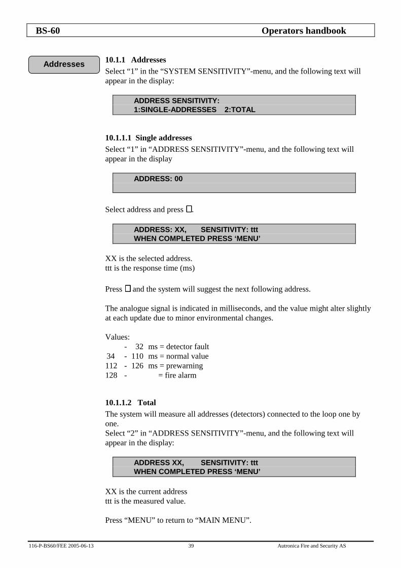
10.1.1 Addresses Select “1” in the “SYSTEM SENSITIVITY”-menu, and the following text will appear in the display:
ADDRESS SENSITIVITY: 1:SINGLE-ADDRESSES 2:TOTAL
10.1.1.1 Single addresses Select “1” in “ADDRESS SENSITIVITY”-menu, and the following text will appear in the display
ADDRESS: 00
Select address and press ↵↵↵↵ .
ADDRESS: XX, SENSITIVITY: ttt WHEN COMPLETED PRESS ‘MENU’
XX is the selected address. ttt is the response time (ms) Press ↵↵↵↵ and the system will suggest the next following address. The analogue signal is indicated in milliseconds, and the value might alter slightly at each update due to minor environmental changes. Values: - 32 ms = detector fault 34 - 110 ms = normal value 112 - 126 ms = prewarning 128 - = fire alarm
10.1.1.2 Total The system will measure all addresses (detectors) connected to the loop one by one. Select “2” in “ADDRESS SENSITIVITY”-menu, and the following text will appear in the display:
ADDRESS XX, SENSITIVITY: ttt WHEN COMPLETED PRESS ‘MENU’
XX is the current address ttt is the measured value. Press “MENU” to return to “MAIN MENU”.
Addresses

BS-60 Operators handbook
116-P-BS60/FEE 2005-06-13 40 Autronica Fire and Security AS
10.1.2 Beyond-limits Select “2” in “SYSTEM SENSITIVITY”-menu, and the following text will appear in the display:
ADDRESSES SENSITIVITY BEYOND LIMITS: HIGH LEVEL: 100 LOW LEVEL: 050
Enter high level value (mS) and press↵↵↵↵ . Enter low value (mS) and press ↵↵↵↵ . The system will measure all addresses (detectors) connected in the loop. Each detector address beyond limits will be indicated for approx. 5 seconds in the display:
SENSITIVITY BEYOND LIMITS TESTING: ADDRESS: XX ttt PRESS ↵ TO STOP
XX is the current address beyond limit. ttt is the measured value (mS) This sequence will automatically be ended when all detector addresses beyond limits are listed, or when ↵↵↵↵ is pressed. The following text will appear in the display:
SENSITIVITY BEYOND LIMIT TESTING: ALL EXAMINED. NN BEYOND LIMITS
NN is the number of detectors beyond limits. Press ↵↵↵↵ to restart the “SENSITIVITY BEYOND LIMIT TESTING” or “MENU” to return to “MAIN MENU”.
10.2 Internal Select “INTERNAL” by pressing “2” in the “SYSTEM”-menu, and the following text will appear in the display:
SYSTEM INTERNAL: 1:PROGRAM-VERSION 2:ADJUST-CLOCK 3:SHOW-CLOCK
The “ADJUST-CLOCK” and the “SHOW-CLOCK” function is only available when the switch S18.7 in position “ON”.
Internal
BS-60 Operators handbook
116-P-BS60/FEE 2005-06-13 41 Autronica Fire and Security AS
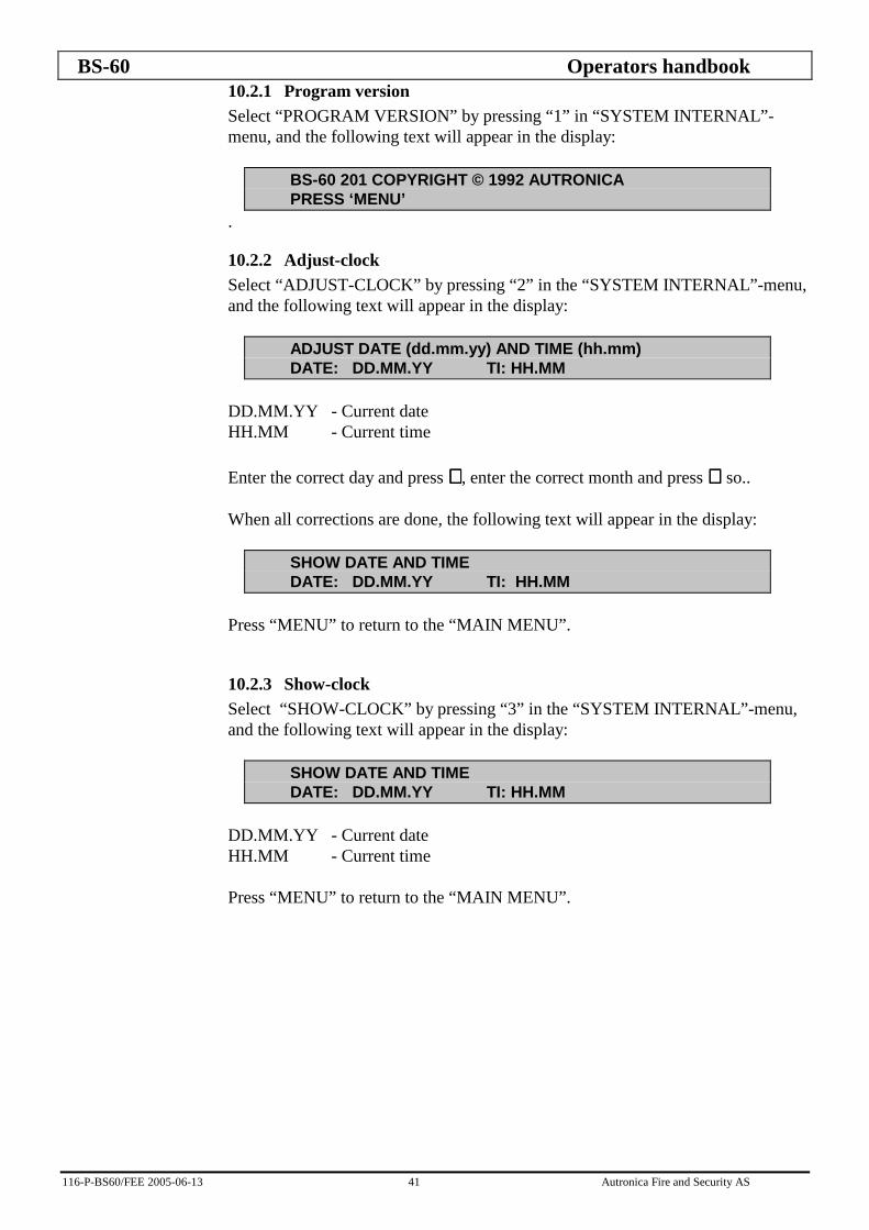
10.2.1 Program version Select “PROGRAM VERSION” by pressing “1” in “SYSTEM INTERNAL”-menu, and the following text will appear in the display:
BS-60 201 COPYRIGHT © 1992 AUTRONICA PRESS ‘MENU’
.
10.2.2 Adjust-clock Select “ADJUST-CLOCK” by pressing “2” in the “SYSTEM INTERNAL”-menu, and the following text will appear in the display:
ADJUST DATE (dd.mm.yy) AND TIME (hh.mm) DATE: DD.MM.YY TI: HH.MM
DD.MM.YY - Current date HH.MM - Current time Enter the correct day and press ↵↵↵↵ , enter the correct month and press ↵ ↵ ↵ ↵ so.. When all corrections are done, the following text will appear in the display:
SHOW DATE AND TIME DATE: DD.MM.YY TI: HH.MM
Press “MENU” to return to the “MAIN MENU”.
10.2.3 Show-clock Select “SHOW-CLOCK” by pressing “3” in the “SYSTEM INTERNAL”-menu, and the following text will appear in the display:
SHOW DATE AND TIME DATE: DD.MM.YY TI: HH.MM
DD.MM.YY - Current date HH.MM - Current time Press “MENU” to return to the “MAIN MENU”.

BS-60 Operators handbook
116-P-BS60/FEE 2005-06-13 42 Autronica Fire and Security AS
10.3 Configuration See "Commissioning handbook" - BS-60 sec. 4 - Configuration.
11. Service See "Commissioning handbook" - BS-60 sec. 5 - Service.
Configuration
Service

![BS60 BATTERY CHARGER user manual.pdf · BS60 BATTERY CHARGER THIS MANUAL CONTAINS IMPORTANT SAFETY AND OPERATING INSTRUCTIONS [ENGLISH] ... the total power consumption is around 0.03kWh](https://img.pdfslide.us/doc/110x75/5bb69dbd09d3f2d32a8b651b/bs60-battery-charger-user-manualpdf-bs60-battery-charger-this-manual-contains.jpg)