Embed Size (px)
Citation preview

11
FIR
E S
AFE
TY
FIRE SAFETY
Fire Damper
LX-5 in libraries of
GOLD MEDAL MTP 2010
FUN CTION The LX-5 fire dampers are designed for buildings where in the event of a fire the affected zone should be isolated from the other zones, by among others, closing fire dampers, while the ventilation and air conditioning systems should operate normally in the other non-affected zones of the building. The performance criteria are satisfied in case of fire from inside to outside as well as outside to inside or both, respectively.
APPLICATION The LX-5 fire dampers installation is allowed within a duct passing through a vertical and horizontal building
partition or directly in building partition. Once the blade of the damper has been closed, the fire-affected zone is
isolated - fire resistance of partition is maintained what prevents the spread of fire into the adjoining
compartments. Fire damper closes as a result of rise in temperature in ventilation duct above 72°C or 95°C and
activation of fuse or by control signal transmitted from the fire alarm control panel if damper is equipped with
remote control mechanism.
DESCRIPTION
The GRYFIT LX-5 fire damper consists of: – rectangular casing made of galvanized steel sheet alternatively stainless or acid proof steel, – movable damper blade made of fire resistant board, – combination of smoke and fire proof seals of damper blade, – control mechanism and optional EMS module enabling fire damper assessment with the TZ tester,
– optional access door provided with a gasket and a cover with quick clamp lever.
EI 120 (ve-ho-i o) S
EN 13501-3+A1:2010
EN 15650:2010
Certificate of Conformity 1488-CPD-0279/W
Damper tightness class: 4 Casing tightness class: C
EN-1751:2002
air
ha
nd
lin
g i
nte
llig
en
ce
Fire Safety
LX-5 SELECTION
BASIC CHARACTERISTICS OF LX-5 WITH RECTAN GULAR FLANGE CONN ECTION
L H
200 250 300 315 350 400 500 600 630 700 800 900 1000 1100 1200 1300 1400 1500
200
2,85 0,86
8
3,60 0,79 10
4,35 0,78 11
4,58 0,77 11
5,10 0,75 13
5,85 0,75 14
7,35 0,72 17
8,85 0,71 20
9,30 0,70 22
10,35 0,70 23
11,85 0,69 26
13,35 0,68 29
14,85 0,68 32
16,35 0,68 35
17,85 0,67 38
19,35 0,67 41
20,85 0,67 44
22,35 0,66 47
S K M
250 3,80 0,70 10
4,80 0,66 12
5,80 0,65 13
6,10 0,64 13
6,80 0,60 15
7,80 0,59 16
9,80 0,57 19
11,80 0,55 22
12,40 0,54 24
13,80 0,54 25
15,80 0,53 26
17,80 0,53 31
19,80 0,52 34
21,80 0,52 37
23,80 0,51 40
25,80 0,51 43
27,80 0,51 46
29,80 0,51 49
S K M
300 4,75 0,63 11
6,00 0,57 13
7,25 0,55 14
7,63 0,52 14
8,50 0,51 16
9,75 0,50 19
12,25 0,48 22
14,75 0,46 25
15,50 0,45 26
17,25 0,45 28
19,75 0,44 31
22,25 0,43 34
24,75 0,42 37
27,25 0,42 40
29,75 0,42 43
32,25 0,41 46
34,75 0,41 49
37,25 0,41 52
S K M
315 5,04 0,60 11
6,36 0,55 13
7,69 0,52 14
8,08 0,51 14
9,01 0,50 16
10,34 0,47 19
12,99 0,45 22
15,64 0,43 25
16,43 0,43 26
18,29 0,42 28
20,94 0,41 31
23,59 0,41 34
26,24 0,40 37
28,89 0,40 40
31,54 0,39 43
34,19 0,39 46
36,84 0,38 49
39,49 0,38 52
S K M
400 6,65 0,52 14
8,40 0,45 16
10,15 0,43 17
10,68 0,42 17
11,90 0,39 19
13,65 0,38 22
17,15 0,35 25
20,65 0,33 28
21,70 0,33 29
24,15 0,32 31
27,65 0,31 34
31,15 0,30 37
34,65 0,30 40
38,15 0,29 43
41,65 0,29 46
45,15 0,28 49
48,65 0,28 52
52,15 0,28 55
S K M
500
8,85 0,45 17
10,80 0,39 19
13,05 0,36 20
13,73 0,34 20
15,30 0,32 22
17,55 0,31 25
22,05 0,28 28
26,55 0,26 31
27,90 0,26 32
31,05 0,25 34
35,55 0,24 37
40,05 0,24 40
44,55 0,23 43
49,05 0,23 46
53,55 0,23 49
58,05 0,22 52
62,55 0,22 55
67,05 0,22 58
S K M
600 10,45 0,41 20
13,20 0,34 22
15,95 0,31 23
16,78 0,30 23
18,70 0,28 25
21,45 0,26 28
26,95 0,23 31
32,45 0,23 34
34,10 0,22 35
37,95 0,22 37
43,45 0,21 40
48,95 0,21 43
54,45 0,20 46
59,95 0,20 49
65,45 0,20 52
70,95 0,20 55
76,45 0,20 58
81,95 0,20 61
S K M
630 11,02 0,40 23
13,92 0,34 25
16,82 0,30 26
17,69 0,28 26
19,72 0,27 28
22,62 0,25 31
28,42 0,23 34
34,22 0,22 37
35,96 0,22 38
40,02 0,21 40
45,82 0,21 43
51,62 0,20 46
57,42 0,20 49
63,22 0,20 52
69,02 0,20 55
74,82 0,19 58
80,62 0,19 61
86,42 0,19 64
S K M
700
12,35 0,38 26
15,60 0,31 28
18,85 0,28 29
19,83 0,26 29
22,10 0,25 31
25,35 0,24 34
31,85 0,22 37
38,35 0,21 40
40,30 0,20 41
44,85 0,20 43
51,35 0,20 46
57,85 0,19 49
64,35 0,19 52
70,85 0,19 55
77,35 0,19 58
83,85 0,19 61
90,35 0,19 64
96,85 0,19 67
S K M
800
14,25 0,35 29
18,00 0,29 31
21,75 0,26 32
22,88 0,25 32
25,50 0,23 34
29,25 0,22 37
36,75 0,20 40
44,25 0,20 43
46,50 0,20 44
51,75 0,19 46
59,25 0,19 49
66,75 0,19 52
74,25 0,19 55
81,75 0,18 58
89,25 0,18 61
96,75 0,18 64
104,25 0,18 67
111,75 0,18 70
S K M
900
16,15 0,33 32
20,40 0,27 34
24,65 0,24 35
25,93 0,23 35
28,90 0,22 37
33,15 0,21 40
41,65 0,20 43
50,15 0,19 46
52,70 0,19 47
58,65 0,19 49
67,15 0,19 52
75,65 0,19 55
84,15 0,18 58
92,65 0,18 61
101,15 0,18 64
109,65 0,18 67
S K M
1000 18,05 0,32 35
22,80 0,26 37
27,55 0,23 38
28,98 0,22 38
32,30 0,21 40
37,05 0,20 43
46,55 0,19 46
56,05 0,18 49
58,90 0,18 50
65,55 0,18 52
75,05 0,18 55
84,55 0,18 58
94,05 0,18 61
103,55 0,18 64
113,05 0,18 67
S K M
1100 19,95 0,31 38
25,20 0,25 40
30,45 0,22 41
32,03 0,21 41
35,70 0,20 43
40,95 0,20 46
51,45 0,19 49
61,95 0,18 52
65,10 0,18 53
72,45 0,18 55
82,95 0,18 58
93,45 0,18 61
103,95 0,18 64
S K M
1200 21,85 0,30 41
27,60 0,24 43
33,35 0,22 44
35,08 0,21 44
39,10 0,20 46
44,85 0,19 49
56,35 0,18 52
67,85 0,18 55
71,30 0,18 56
79,35 0,18 58
90,85 0,18 61
102,35 0,18 64
113,85 0,18 67
S K M
Legend:
– for dimensions not listed in this table assembly in multiple arrangement of fire dampers is provided
– fields shaded in gray are beyond the dimensional range
S – effective area [dm2], M – weight [kg], K – correction value for acoustic calculations
L – dimension of the damper sides without actuator [mm], H – dimension of the damper sides with actuator [mm]
DIM EN SION S OF LX-5 WITH RECTAN GULAR FLANGE CONN ECTION
The dimensions of the open blade
of the damper mounted in the vertical
concrete or masonry partition G = 110 mm
H [mm]
F [mm]
M [mm]
200 0,5 - 250 25,5 - 300 50,5 -
315 58,0 - 350 85,5 - 400 100,5 - 500 150,5 40,5
600 200,5 90,5 630 215,5 105,5 700 250,5 140,5 800 300,5 190,5
900 350,5 240,5
1000 400,5 290,5 1100 450,5 340,5 1200 500,5 390,5
12
50
290
70 145
F M
40
G
H x
L
Hr
x Lr
Fire Safety
LX-5 SELECTION
13
Eff
ect
ive
velo
city
Vk [
m/s
]
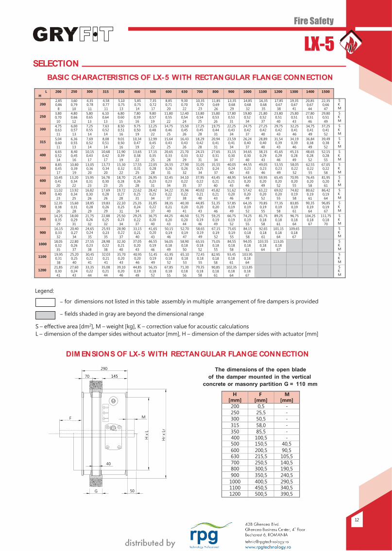
DIM EN SION S OF LX-5 WITH CIRCULAR SLEEVE CONN ECTION
D
[mm]
L and H
[mm]
P
[mm]
A
[mm]
B
[mm]
C
[mm]
Weight
[kg]
K
[ - ]
S
[dm2]
100
200
310,0 90,0 180,0 145,0 9 0,86 2,2
125 310,0 90,0 180,0 145,0 9 0,86 2,2
150 310,0 90,0 180,0 145,0 9 0,86 2,2
160 310,0 90,0 180,0 145,0 9 0,86 2,2
200 310,0 90,0 180,0 145,0 9 0,86 2,2
250 250 370,0 150,0 180,0 145,0 14 0,66 4,0
300 300 370,0 150,0 180,0 145,0 17 0,55 6,2
315 315 370,0 150,0 180,0 145,0 17 0,51 7,0
350 350 400,0 180,0 180,0 145,0 23 0,44 9,0
400 400 400,0 180,0 180,0 145,0 28 0,38 12,2
500 500 540,0 250,0 250,0 215,0 41 0,28 20,2
600 600 640,0 300,0 300,0 265,0 55 0,23 30,2
630 630 640,0 300,0 300,0 265,0 61 0,22 33,6
700 700 740,0 350,0 350,0 315,0 71 0,20 42,2
800 800 840,0 400,0 400,0 365,0 87 0,19 56,2
900 900 940,0 450,0 450,0 415,0 105 0,19 72,2
1000 1000 1040,0 500,0 500,0 465,0 125 0,18 90,2
PRESSURE DROP AND SOUN D POW ER LEVEL
Air flow [m3/h] Correction value for
acoustic calculations
10 10
9 9
8 8
7 7
6 6
5 5
4 4
3 3
2 2
45
40
35
Lw= 30 [dB(A)]
1
1 2 4 6 8 10 20
40 60
1
80 100 1 2
4 6 8 10
20 40
60 80 100
Effective area S [dm2] Pressure drop [Pa]
Legend:
Lw – acoustic pressure level inside damper [dB(A)], K - correction value from tables above
Example: Air flow = 1000 [m3/h] K = 0,51 [ – ]
L x H S
= 315 x 315 [mm] = 0,7 [dm2 ]
Lw
∆P = 31 = 4
[dB(A)] [Pa]
P
C 50
40
A B
Eff
ect
ive
velo
city
Vk [
m/s
]
Ø D
14
Fire Safety
LX-5
1
5 2
Mortaring border
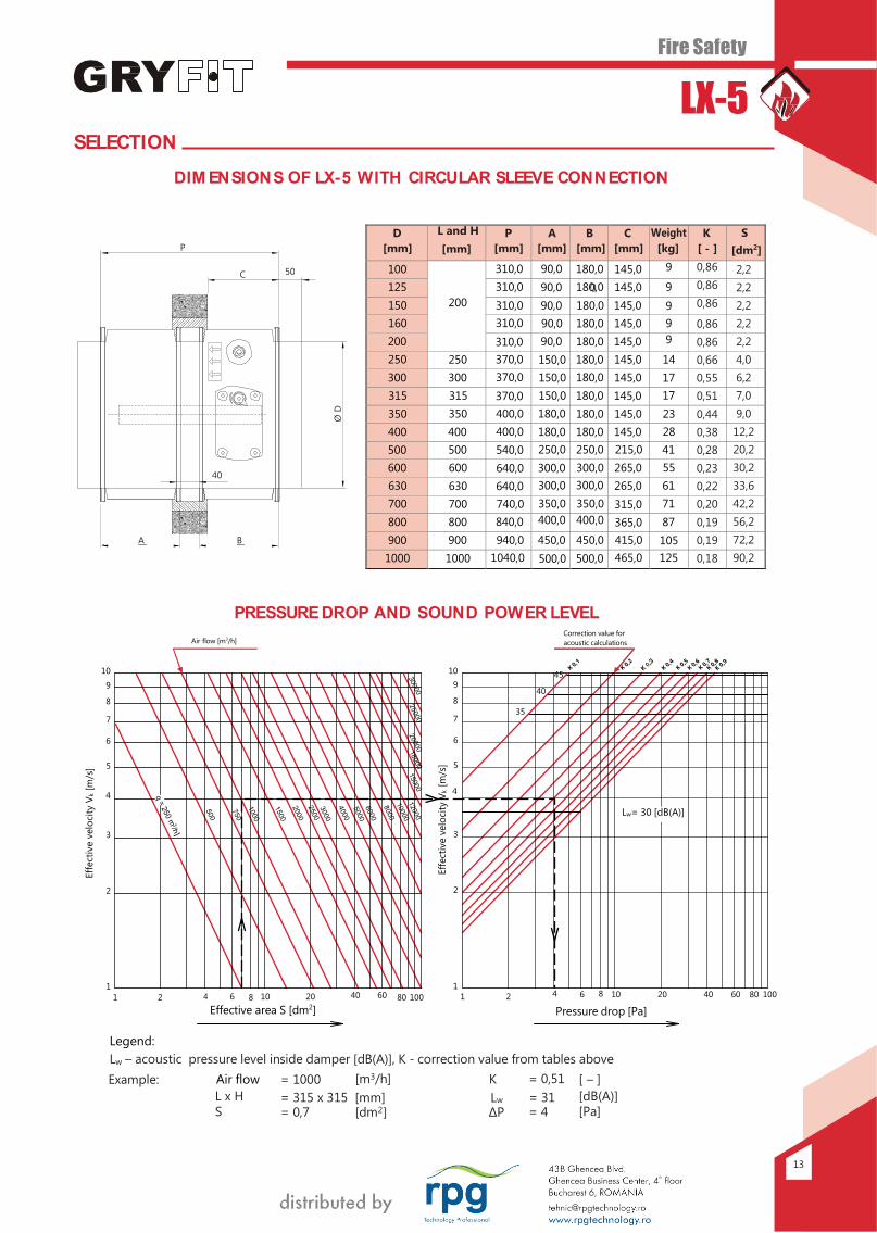
M ETHOD OF IN STALLATION
IN STALLATION OF FIRE DAM PER IN PARTITION WALL
Detail "A"
Installation of fire dampers in partition: – horizontal, – vertical.
M inimum installation opening: Concrete or brick walls Lr x Hr = (L + 90) x (H + 90)
1 - - Partition
wall
M ortaring border:
– is clearly marked by the label on the casing, – damper blade should align with the center line of
the partition wall’s thickness, – if mortaring in wall or ceiling, mortaring border
marking on the fire damper must be strictly observe.
The GRYFIT fire damper can be installed with it’s blade axis positioned horizontally as well as vertically.
2 - - Cement – lime mortar*
* Not delivered by GRYFIT
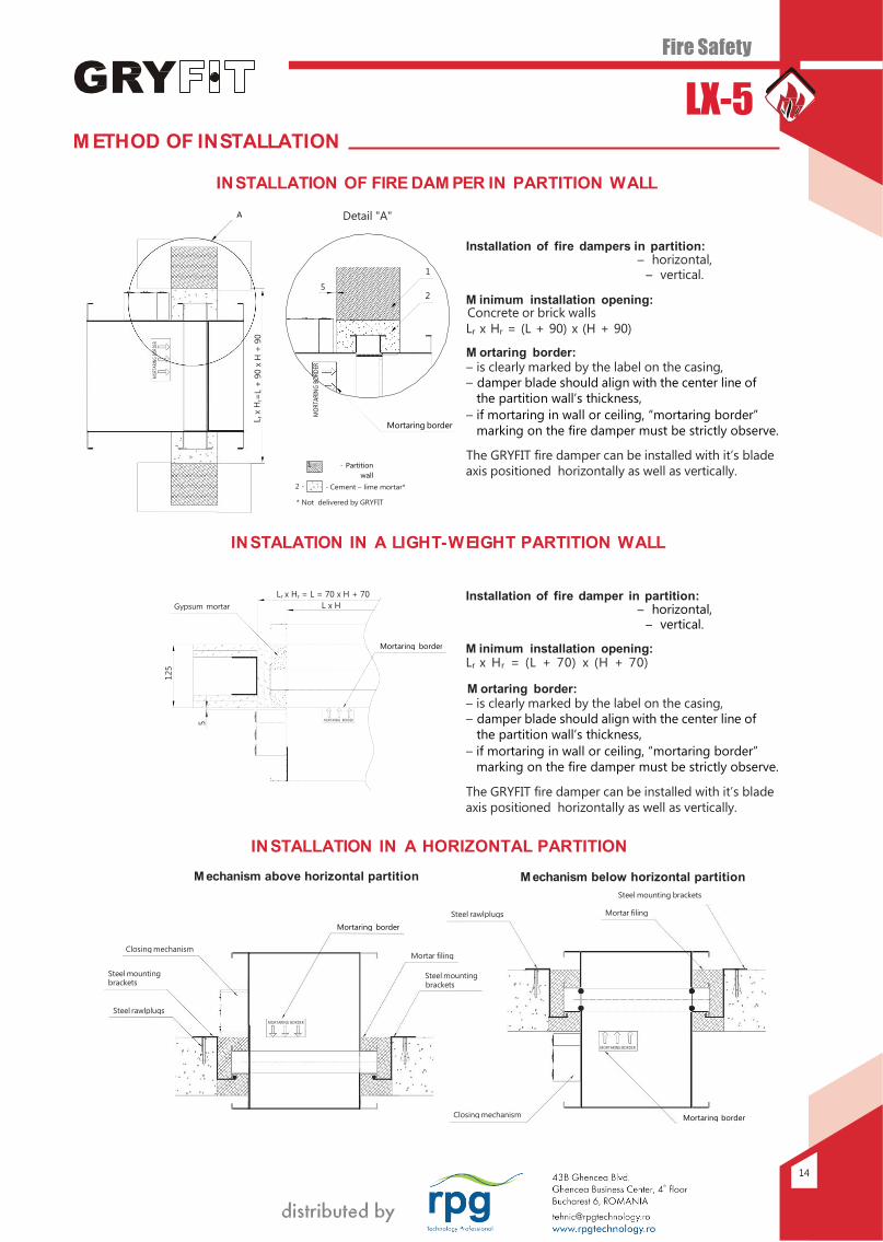
IN STALATION IN A LIGHT-W EIGHT PARTITION WALL
Installation of fire damper in partition: – horizontal, – vertical.
M inimum installation opening: Lr x Hr = (L + 70) x (H + 70)
M ortaring border:
– is clearly marked by the label on the casing, – damper blade should align with the center line of
the partition wall’s thickness, – if mortaring in wall or ceiling, mortaring border
marking on the fire damper must be strictly observe.
The GRYFIT fire damper can be installed with it’s blade axis positioned horizontally as well as vertically.
IN STALLATION IN A HORIZONTAL PARTITION
M echanism above horizontal partition M echanism below horizontal partition
Steel mounting brackets
Steel rawlplugs Mortar filing
Mortaring border
Closing mechanism Mortar filing
Steel mounting brackets
Steel mounting brackets
Steel rawlplugs
MORTARING BORDER
MORTARING BORDER
Closing mechanism Mortaring border
A
Gypsum mortar
Lr x Hr = L = 70 x H + 70 L x H
Mortaring border
MORTARING BORDER
MO
RTAR
ING B
ORD
ER
125
5
L r x
Hr=
L +
90 x
H +
90
MO
RTA
RIN
G B
OR
DER
Fire Safety
LX-5
15
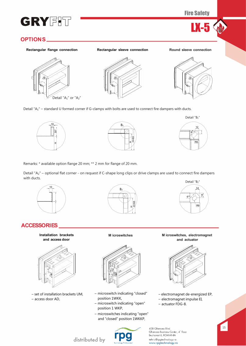
OPTIONS
Rectangular flange connection Rectangular sleeve connection Round sleeve connection
Detail "A1" or "A2"
Detail "A1" – standard U formed corner if G-clamps with bolts are used to connect fire dampers with ducts.
Detail "B1"
Remarks: * available option flange 20 mm; ** 2 mm for flange of 20 mm.
Detail "A2" – optional flat corner - on request if C-shape long clips or drive clamps are used to connect fire dampers
with ducts. Detail "B2"
ACCESSORIES
Installation brackets
and access door
M icroswitches M icroswitches, electromagnet
and actuator
– set of installation brackets UM,
– access door AD,
– microswitch indicating "closed"
position 1WKK,
– microswitch indicating "open"
position 1 WKP,
– microswitches indicating "open"
and "closed" position 1WKKP,
– electromagnet de-energized EP,
– electromagnet impulse EI,
– actuator FDG-8.
10
10 B1 12
R6
B2 14
6**
R6
H
30
*
H H+
63
H H+
63
14
16
Fire Safety
LX-5
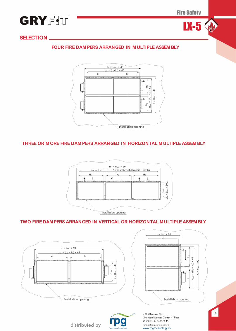
Hr = Hbat. + 90
Hbat. = (H1 + H2 + H3) + (number of dampers - 1) x 65
Installation opening
SELECTION
FOUR FIRE DAM PERS ARRANGED IN M ULTIPLE ASSEM BLY
THREE OR M ORE FIRE DAM PERS ARRANGED IN HORIZONTAL M ULTIPLE ASSEM BLY
TWO FIRE DAM PERS ARRANGED IN VERTICAL OR HORIZONTAL M ULTIPLE ASSEM BLY
H3 H2 H1
Lr = Lbat. + 90 Lbat.
Installation opening
Lr = Lbat. + 90
Lbat. = (L1 + L2) + 65 L1 L2
Installation opening
Lr = Lbat. + 90 Lbat. = (L1+L2) + 65 L1 L2
Installation opening
Hb
at.
Hr
= H
bat.
+ 9
0
H1
H2
Hb
at.
= (
H1+
H2)
+ 6
5
Hr
= H
bat.
+ 9
0
L bat.
L r =
Lb
at.
+ 9
0
H2
H
1
Hb
at.
= (
H1
+ H
2)
+ 6
5
Hr
= H
bat.
+ 9
0
Fire Safety
LX-5 ELECTRICAL WIRING DIAGRAM S
7
EM
Yello
w -
gre
en
wir
e -
23
0 V
on
ly
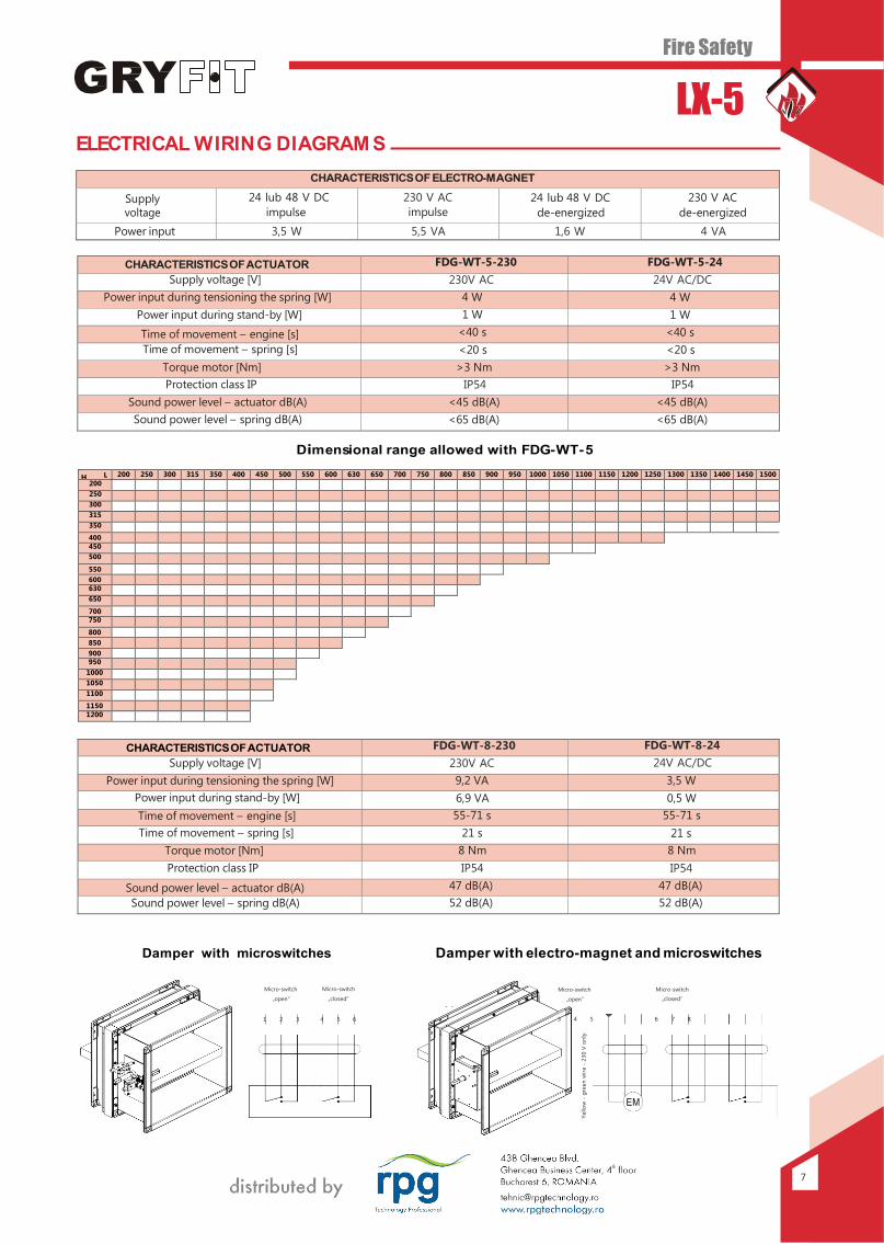
CHARACTERISTICS OF ELECTRO-M AGNET
Supply voltage
24 lub 48 V DC
impulse
230 V AC
impulse 24 lub 48 V DC
de-energized
230 V AC
de-energized
Power input 3,5 W 5,5 VA 1,6 W 4 VA
CHARACTERISTICS OF ACTUATOR FDG-WT-5-230 FDG-WT-5-24
Supply voltage [V] 230V AC 24V AC/DC
Power input during tensioning the spring [W] 4 W 4 W
Power input during stand-by [W] 1 W 1 W
Time of movement – engine [s] <40 s <40 s
Time of movement – spring [s] <20 s <20 s
Torque motor [Nm] >3 Nm >3 Nm
Protection class IP IP54 IP54
Sound power level – actuator dB(A) <45 dB(A) <45 dB(A)
Sound power level – spring dB(A) <65 dB(A) <65 dB(A)
Dimensional range allowed with FDG- WT- 5
H L 200 250 300 315 350 400 450 500 550 600 630 650 700 750 800 850 900 950 1000 1050 1100 1150 1200 1250 1300 1350 1400 1450 1500
200
250
300
315
350
400 450
500
550 600 630
650
700 750
800 850 900 950
1000
1050
1100
1150 1200
CHARACTERISTICS OF ACTUATOR FDG-WT-8-230 FDG-WT-8-24
Supply voltage [V] 230V AC 24V AC/DC
Power input during tensioning the spring [W] 9,2 VA 3,5 W
Power input during stand-by [W] 6,9 VA 0,5 W
Time of movement – engine [s] 55-71 s 55-71 s
Time of movement – spring [s] 21 s 21 s
Torque motor [Nm] 8 Nm 8 Nm
Protection class IP IP54 IP54
Sound power level – actuator dB(A) 47 dB(A) 47 dB(A)
Sound power level – spring dB(A) 52 dB(A) 52 dB(A)
Damper with microswitches Damper with electro-magnet and microswitches
Micro-switch
Micro-switch
Micro-switch
Micro-switch
„open „closed
„open „closed
1 2 3
4 5 6
3 4 5
6 7 8
Fire Safety
LX-5 ELECTRICAL WIRING DIAGRAM S
18
1 2 21 22 23 24 25 26
M <5°
<80°
230 V AC + - -
N +
L1
230 V AC MICROSWITCHES
3 4 1 2 5 6 7 8 9 10
EMS
1 2 1 2 21 22 23 24 25 26
EM M <5°
<80°
Desi
gn c
hang
es
rese
rved
. All
rig
hts
rese
rved
.© G
RYFIT
air
hand
ling
in
telli
gen
ce -
LX
-5-1
6.0
9-B
.4-E
NG
.
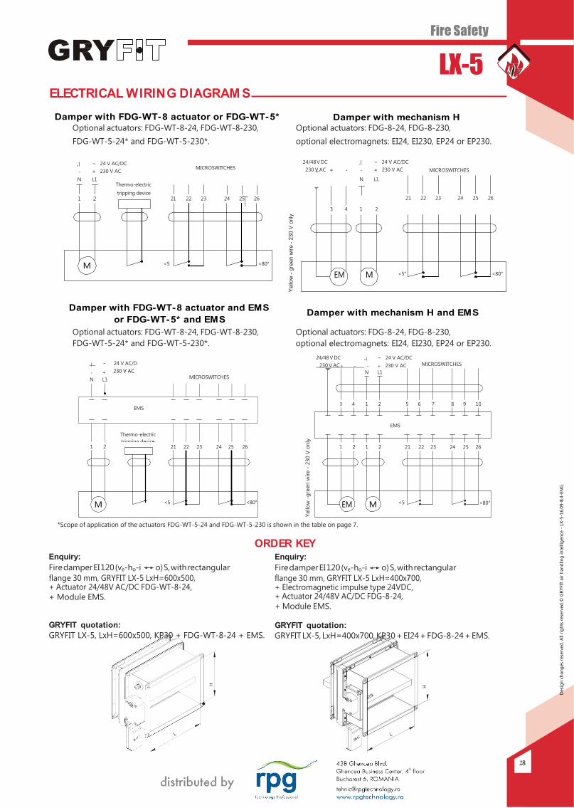
Damper with FDG- WT- 8 actuator or FDG- WT- 5* Damper with mechanism H Optional actuators: FDG-WT-8-24, FDG-WT-8-230, Optional actuators: FDG-8-24, FDG-8-230,
FDG-WT-5-24* and FDG-WT-5-230*. optional electromagnets: EI24, EI230, EP24 or EP230.
~ 24 V AC/DC
- + 230 V AC
MICROSWITCHES 24/48 V DC
230 V AC + -
~ 24 V AC/DC
- + 230 V AC
MICROSWITCHES
N L1
Thermo-electric
tripping device
N L1
3 4 1 2
21 22 23 24 25 26
EM M <5° <80°
Damper with FDG- WT- 8 actuator and EM S
or FDG- WT- 5* and EM S
Damper with mechanism H and EM S
Optional actuators: FDG-WT-8-24, FDG-WT-8-230, Optional actuators: FDG-8-24, FDG-8-230,
FDG-WT-5-24* and FDG-WT-5-230*. optional electromagnets: EI24, EI230, EP24 or EP230.
~
- +
N L1
24 V AC/D
230 V AC
MICROSWITCHES
24/48 V DC
~ 24 V AC/DC
*Scope of application of the actuators FDG-WT-5-24 and FDG-WT-5-230 is shown in the table on page 7.
ORDER KEY Enquiry:
Fire damper EI 120 (ve-ho-i o) S, with rectangular
flange 30 mm, GRYFIT LX-5 LxH=600x500, + Actuator 24/48V AC/DC FDG-WT-8-24, + Module EMS.
GRYFIT quotation:
GRYFIT LX-5, LxH=600x500, KP30 + FDG-WT-8-24 + EMS.
Enquiry:
Fire damper EI 120 (ve-ho-i o) S, with rectangular
flange 30 mm, GRYFIT LX-5 LxH=400x700, + Electromagnetic impulse type 24VDC, + Actuator 24/48V AC/DC FDG-8-24, + Module EMS.
GRYFIT quotation:
GRYFIT LX-5, LxH=400x700, KP30 + EI24 + FDG-8-24 + EMS.
1 2 21 22 23 24 25 26
M <5°
<80°
H
Yello
w -
gre
en
wir
e -
23
0 V
only
Yello
w -
gre
en
wir
e -
230 V
on
ly
H
EMS
Thermo-electric
tripping device