Embed Size (px)
Citation preview
1
Proceedings of the
Annual Stability Conference
Structural Stability Research Council
St. Louis, Missouri, April 16-20, 2013
Finite prism elastic buckling analysis and application in steel foam sandwich
members
Z. Li1, S. Szyniszewski 2 Abstract
The objective of this research is to develop a layer-wise finite prism method for studying the elastic buckling of steel foam sandwich members. Foamed steel, literally steel with internal voids, enables lightweight and stiff components. Steel foam sandwich panels (steel face sheets and low-density, highly porous foam core) exhibit higher bending rigidity and plate buckling strength in comparison to slender, steel plates with the same weight. Analytical sandwich plate buckling solutions are not applicable to buckling analysis of cold-formed sandwich members with interaction between local and global buckling modes. Finite element analysis (either solid 3D or shell representation) provides the most reliable solution; however, its use is complicated, computationally expensive, and not practical for engineers. The proposed layer-wise finite prism solution is an alternative, easy-to-use tool, which builds upon the shape functions available in the literature, and is verified against eigenbuckling finite element solutions implemented in LS-DYNA software. Future research is needed to incorporate the elastic buckling solutions in the direct strength design of sandwich panel members.
1. Introduction
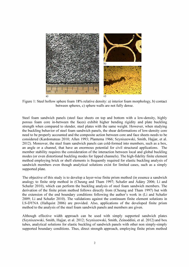
Foamed steel intentionally introduces internal voids in steel, e.g. Figure 1. A number of manufacturing methods are used to introduce the voids from powder metallurgy and sintering of hollow spheres to gasification (Ashby 2000). Steel foams are largely still under development, e.g. (Kremer, Liszkiewicz, and Adkins 2004); however steel foam sandwich panels have been utilized in a demonstration project as a parking garage slab (Hipke 2011) while mass production of aluminum foam sandwich panels already exists (Banhart and Seeliger, 2008). In general, metal foams have high effective bending stiffness and energy absorption. In addition, metal foams have improved thermal conductivity (Neugebauer et al. 2005), enhanced fire resistance (Coquard, Rochais, and Baillis 2010), better noise attenuation (Ashby 2000; Bao and Han 2009), and provide improved electromagnetic and radiation shielding (Losito, Barletta, and Dimiccoli 2010; Xu, Bourham, and Rabiei 2010) when compared with solid metals. A review of applications of metal foams can be found in Smith et al. (2012).
1 Postdoctoral Research Associate, Dept. of Civil Engineering, Johns Hopkins University, <[email protected]> 2 Assistant Professor, Dept. of Civil Engineering, University of Surrey, <[email protected]>
2
a)
b)
c)
Figure 1: Steel hollow sphere foam 18% relative density: a) interior foam morphology, b) contact between spheres, c) sphere walls are not fully dense.
Steel foam sandwich panels (steel face sheets on top and bottom with a low-density, highly porous foam core in-between the faces) exhibit higher bending rigidity and plate buckling strength when compared to slender, steel plates with the same weight. However, when studying the buckling behavior of steel foam sandwich panels, the shear deformations of low-density core need to be properly accounted and the composite action between core and face sheets needs to be considered (Kardomateas 2010; Allen 1993; Plantema 1966; Szyniszewski, Smith, Hajjar, et al. 2012). Moreover, the steel foam sandwich panels can cold-formed into members, such as a box, an angle or a channel, that have an enormous potential for civil structural applications. The member stability requires the consideration of the interaction between local and global buckling modes (or even distortional buckling modes for lipped channels). The high-fidelity finite element method employing brick or shell elements is frequently required for elastic buckling analysis of sandwich members even though analytical solutions exist for limited cases, such as a simply supported plate. The objective of this study is to develop a layer-wise finite prism method (in essence a sandwich analogy to finite strip method in (Cheung and Tham 1997; Schafer and Ádány 2006; Li and Schafer 2010), which can perform the buckling analysis of steel foam sandwich members. The derivation of the finite prism method follows directly from (Cheung and Tham 1997) but with the extension of the end boundary conditions following the author’s work in (Li and Schafer 2009; Li and Schafer 2010). The validations against the continuum finite element solutions in LS-DYNA (Hallquist 2006) are provided. Also, applications of the developed finite prism method to the analysis of the steel foam sandwich panels and members are given. Although effective width approach can be used with simply supported sandwich plates (Szyniszewski, Smith, Hajjar, et al. 2012; Szyniszewski, Smith, Zeinoddini, et al. 2012) and box tubes, analytical solutions for elastic buckling of sandwich panels with other non simply-simply supported boundary conditions. Thus, direct strength approach, employing finite prism method
3
for the calculation of elastic buckling modes, can facilitate efficient and general design procedures for sandwich members of any cross-sectional shape, and undergoing complex, interactive buckling modes. 2. Finite strip method and application to steel foam members
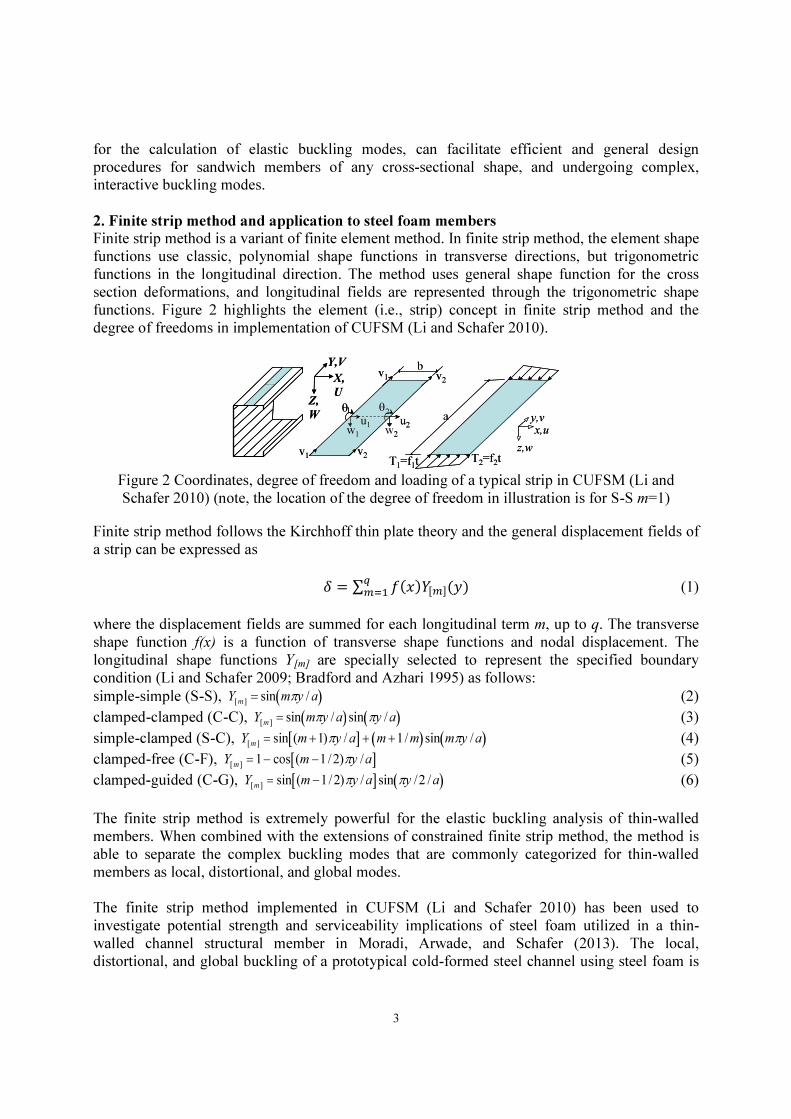
Finite strip method is a variant of finite element method. In finite strip method, the element shape functions use classic, polynomial shape functions in transverse directions, but trigonometric functions in the longitudinal direction. The method uses general shape function for the cross section deformations, and longitudinal fields are represented through the trigonometric shape functions. Figure 2 highlights the element (i.e., strip) concept in finite strip method and the degree of freedoms in implementation of CUFSM (Li and Schafer 2010).
Figure 2 Coordinates, degree of freedom and loading of a typical strip in CUFSM (Li and Schafer 2010) (note, the location of the degree of freedom in illustration is for S-S m=1)
Finite strip method follows the Kirchhoff thin plate theory and the general displacement fields of a strip can be expressed as
� = ∑ ��������(�)���� (1)
where the displacement fields are summed for each longitudinal term m, up to q. The transverse shape function f(x) is a function of transverse shape functions and nodal displacement. The longitudinal shape functions Y[m] are specially selected to represent the specified boundary condition (Li and Schafer 2009; Bradford and Azhari 1995) as follows: simple-simple (S-S), Y[m] = sin mπy /a( ) (2) clamped-clamped (C-C), Y[m]
= sin mπy /a( ) sin πy /a( ) (3) simple-clamped (S-C), Y[m] = sin (m +1)πy /a[ ] + m +1/m( ) sin mπy /a( ) (4) clamped-free (C-F), Y[m] =1− cos (m −1/2)πy /a[ ] (5) clamped-guided (C-G), Y[m]
= sin (m −1/2)πy /a[ ] sin πy /2 /a( ) (6) The finite strip method is extremely powerful for the elastic buckling analysis of thin-walled members. When combined with the extensions of constrained finite strip method, the method is able to separate the complex buckling modes that are commonly categorized for thin-walled members as local, distortional, and global modes. The finite strip method implemented in CUFSM (Li and Schafer 2010) has been used to investigate potential strength and serviceability implications of steel foam utilized in a thin-walled channel structural member in Moradi, Arwade, and Schafer (2013). The local, distortional, and global buckling of a prototypical cold-formed steel channel using steel foam is
v1 v
2
b
x,u
y,v
z,w
a
T1=f
1t T
2=f
2t
u1
w1
θ1
u2
w2
θ2
v1
v2
Y,V
X,
UZ,
W
v1 v
2
b
x,u
y,v
z,w
a
T1=f
1t T
2=f
2t
u1
w1
θ1
u2
w2
θ2
v1
v2
Y,V
X,
UZ,
W
4
examined by finite strip method. For steel foam member studied in Moradi, Arwade, and Schafer (2013), the width to thickness ratio of the web is greater than 10 for which shear deformations are assumed to be negligible. Although finite strip method is powerful for the member stability analysis, it lacks the ability to handle the sandwich sections. The analysis of the sandwich panel sections can be accomplished with either a layer-wise finite strip method, accounting for shear through the thickness (important in soft material such steel foam) or with a finite prism method using continuum mechanics. In this paper, the finite prism method is developed and validated in order to facilitate fast and efficient buckling analysis of steel foam sandwich panels and members. 3. Finite prism method
Similarly to the finite strip method, the essential idea of finite prism method is to reduce a three-dimensional problem to a two-dimensional one with the displacement functions as
� = ∑ ���, �����(�)���� (7)
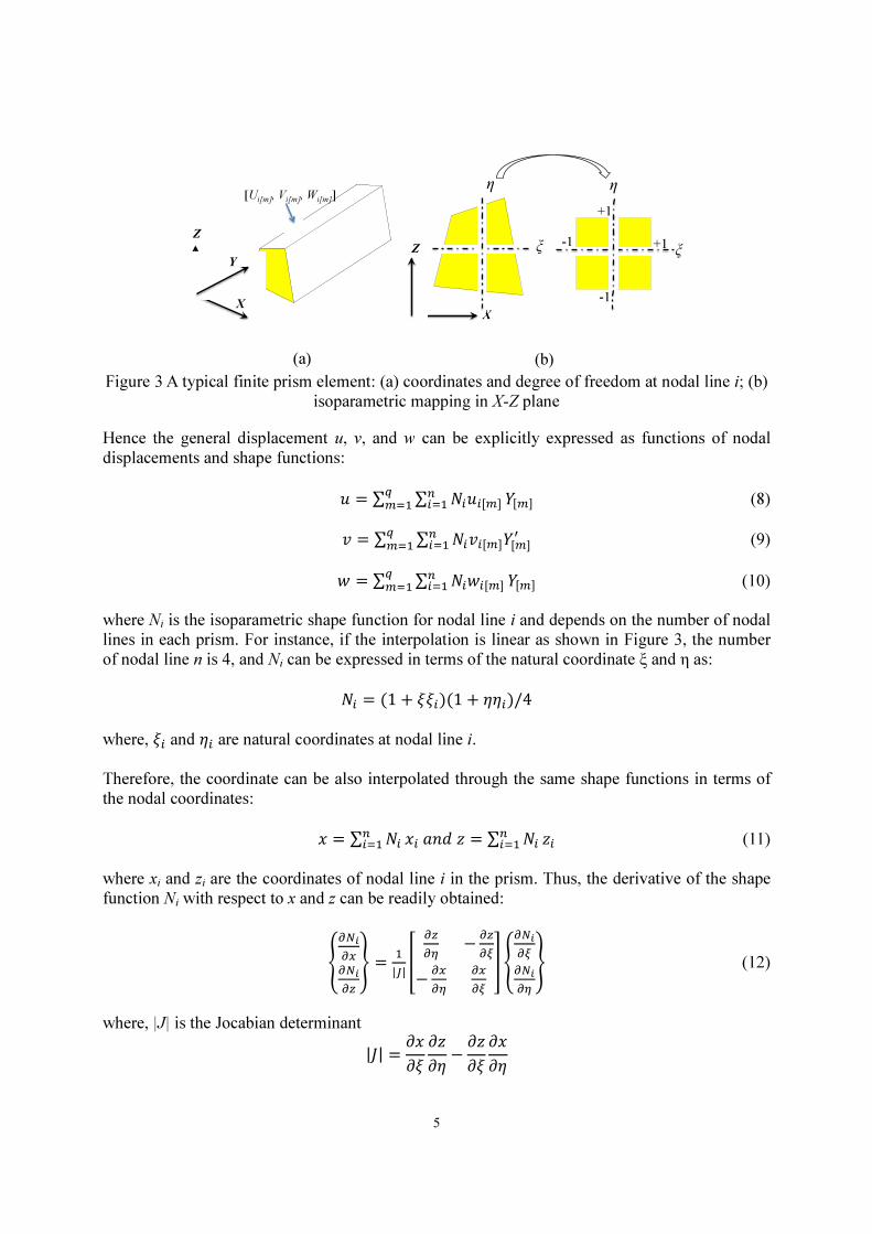
where the displacement fields are summed for each longitudinal term m, up to q; f(x,z) is a function of nodal displacements and shape functions in x-z plane that can be easily formed through an isoparametric element. Note, in essence, the finite strip method follows the same strategy but further reduces to a shell formulation by following the Kirchhoff thin plate theory (see Schafer and Ádány 2006; Li and Schafer 2010). The finite prism method is best suitable for the sections with varying thickness or holes as well as the sandwich panels that consist of different materials, for which the shear deformations and composite actions can be correctly modeled with continuum mechanics. In the finite prism, each cross section, such as the lipped channel in Figure 2, is discretized through the section using quadrilateral mesh. This results in a typical element in a finite prism that is depicted in Figure 3, along with the degrees of freedom (u, v, and w displacements). More specifically, for each node line, the nodal displacements for longitudinal term m are [u[m] v[m]
w[m]]T as shown in (Figure 3, for nodal line i). Note, in Figure 3,the illustration depicts a four-
node linear interpolation of an isoparametric element while the interpolation can be quadratic (8 or 9 nodes) or cubic (12 nodes). Also, the local and global coordinates are the same. Along the longitudinal Y direction, the shape functions Y[m] are specially selected to represent the specified boundary conditions as given in Eq’s. (2)-(6).
5
Figure 3 A typical finite prism element: (a) coordinates and degree of freedom at nodal line i; (b)
isoparametric mapping in X-Z plane
Hence the general displacement u, v, and w can be explicitly expressed as functions of nodal displacements and shape functions:
= ∑ ∑ ���[�]���� ����
���� (8)
� = ∑ ∑ ����[�]�[�]�
������� (9)
= ∑ ∑ �� �[�]���� ����
���� (10)
where Ni is the isoparametric shape function for nodal line i and depends on the number of nodal lines in each prism. For instance, if the interpolation is linear as shown in Figure 3, the number of nodal line n is 4, and Ni can be expressed in terms of the natural coordinate ξ and η as:
�� = (1 + ���)(1 + ���)/4 where, �� and �� are natural coordinates at nodal line i. Therefore, the coordinate can be also interpolated through the same shape functions in terms of the nodal coordinates:
� = ∑ ������ ����� = ∑ ��
���� � (11)
where xi and zi are the coordinates of nodal line i in the prism. Thus, the derivative of the shape function Ni with respect to x and z can be readily obtained:
���
���
� =�
|�|�
�−
�
−�
�
�
�
� ���
�
��
�
� (12)
where, |J| is the Jocabian determinant |�| = ���� ��� −��� ����
Z
Y
X
[Ui[m], Vi[m], Wi[m]]
Z
X
η
ξ
η
ξ -1
-1
+1
+1
(a) (b)
6
For the three-dimensional solid, the strain-displacement relationship can be expressed by the Green-Lagrangian strain tensor as
��� = �
�(�,� + �,�) + �
��,��,� (13)
For the elastic buckling analysis, the elastic stiffness matrix can be derived using the internal strain energy formed by the linear strains while second order strains form the basis of the geometric stiffness matrix.
3.1 Elastic stiffness matrix
By substituting the general displacements (u, v, and w) of the Eq’s. (8)-(10) into Eq. (13), the strain vector can be obtained as
{�} = [�� �� � ����� � �]� = ∑ ∑ ��[�]�[�]����
���� (14)
where Bi[m] is the strain matrix for nodal line i for longitudinal term m that can be explicitly expressed by the derivative of the shape functions as
��[�] =
��������� ��
��[�] 0 0
0 ���[�] 0
0 0��
�[�]���[�]
��
��[�] 0
0��
�[�] ���[�]
��
�[�] 0
��
��[�]!""
""""""# (15)
where ��
� and
��
are the derivatives of Ni with respect to x and z given in Eq. (12).
For orthotropic linear elastic material the compliance matrix S takes the symmetric form,
$ =
���������� �
��−
���
��−
���
��
−���
��
�
��−
���
��
−���
��−
���
��
�
��
0
0
�
���0 0
0�
���0
0 0�
���!"""""""""# (16)
where, Ex, Ey, and Ez are the three Young’s moduli along axes, Gxy, Gyz, and Gzx are the three shear moduli, and vxy, vyz, and vzx are the Poisson’s ratios. Note, for isotropic materials, the compliance matrix can be further simplified by equating Young’s modulus and Poisson’s ratio in
7
all three directions. Therefore, the stiffness matrix C in constitutive law will be the reverse of the compliance matrix S and the stresses are related to the strains as
{%} = &%� %�% '��'� ' �(� = ){*} (17)
The internal strain energy of a prism can then be formulated as + =�
�, {�}�{%}�
�- = ∑ ∑ �
�[�]� ., �[�]
� )�[�]��-/[�]
����
���� = ∑ ∑ �
�[�]� 0�[��][�]
����
����
(18)
where the B[m] is the strain matrix of all the nodal lines in the prism, i.e., Eq. (15) is a submatrix of B[m] for nodal line i, and u[m] is the displacements of all the nodal lines in the prism. The
elastic stiffness matrix corresponding to longitudinal terms m and n is 0�[��] that can be readily integrated from:
0�[��]= , �[�]
� )�[�]��- = ∭�[�]
� )�[�] |�|������ (19)
Through the integration, every element inside stiffness 0�[��] can be separated into two basic integrals: a two-dimensional isoparametric element type integral in X-Z plane that need numerical integration techniques such as Gaussian quadrature and a closed formed integral of trigonometric functions the same as in (Li and Schafer 2010; Li and Schafer 2009). For instance, the linear interpolation in this implementation, 2x2 Gaussian points provides reasonably accurate solution of the stiffness matrix. Finally, the full elastic matrix ke can be expressed as
0� = 20�[��]3��
(20)
Given the longitudinal shape functions chosen here, the stiffness matrix of the finite prism method developed here shares some similarity as the finite strip method in (Schafer and Ádány 2006; Li and Schafer 2010). For the simply-simply (S-S) boundary conditions I1 through I5 are zero when m≠n leaving only a diagonal set of submatrices in ke. For all other boundary conditions ke has non-zero submatrices off the main diagonal and interaction of buckling modes of different half-wavelengths occur.
3.2 Geometric stiffness matrix
The basis of the geometric stiffness matrix is the additional work created by the loading on the second order strains. For the current implementation, only the prism’s shortening in the axial longitudinal direction is considered, which corresponds to the second order terms associated with εy. Hence, the additional work Vp can be written as
-4 =�
�, �∑ ��%��
��� ��
5.��
/� + .��
/� + .��
/�6 �- =∑ ∑ �
�[�]� ., �∑ ��%��
��� �7[�]� 7[�]�
�-/[�] = ∑ ∑ �
�[�]� 0�[��][�]
����
����
����
���� (21)
8
where σi is the longitudinal stress at nodal line i and G[m] is a matrix of all nodal lines consisting the following submatrix of nodal line i as
7�[�] = 8���[�] 0 0
0 ���[�] 0
0 0 ���[�]
9 (22)
The geometric stiffness matrix corresponding to longitudinal terms m and n 0�[��] can be readily integrated from:
0�[��]= , �∑ ��%��
��� �7[�]� 7[�]�
�- = ∭�∑ ��%����� �7[�]
� 7[�] |�|������ (23)
The integration procedure is the same as elastic stiffness matrix, which consists of numerical integration and a close-formed integral. Finally, the full elastic matrix ke can be expressed as
0� = 20�[��]3��
(24)
3.3 Assembly and stability solution
For finite prism method, assembly of the local stiffness matrices (ke and kg) into the global stiffness matrices (Ke and Kg) are similar to the conventional finite element method except that the longitudinal terms complicate the assembly process a bit. There is no coordinate transformation needed unlike in the finite strip method. The global stiffness matrices may be assembled as an appropriate summation of each prism’s stiffness matrices. The following elastic buckling problem can be obtained for a given distribution of nodal stresses in a member:
ΦΛ=Φge
KK (25)
where, Λ is a diagonal matrix containing the eigenvalues (buckling loads) and Φ is a fully populated matrix corresponding to the eigenmodes (buckling modes) in its columns. The resulting orthogonality in Ke and Kg for simply supported boundary conditions makes the solutions for any m independent. For non simply-supported boundary conditions the orthogonality is lost, many longitudinal (m) terms are used. See more details in Li and Schafer (2010) and Li and Schafer (2009).
4. Numerical examples
The studies of plates on both isotropic and steel foam sandwich panels are made to provide validations of the finite prism solutions against finite strip/element solutions. Also, a box section made of steel foam sandwich panels is chosen for the validation of the member against finite element solutions using brick element in LS-DYNA (Hallquist 2006).
9
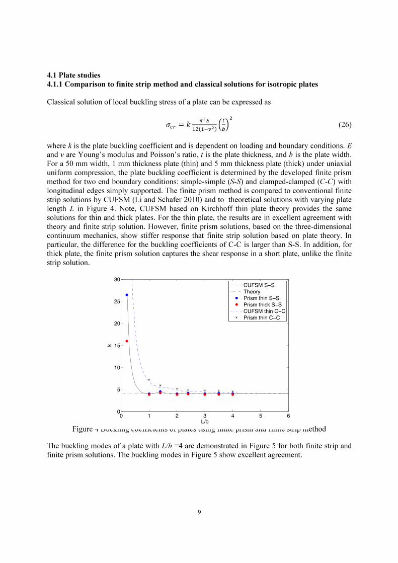
4.1 Plate studies
4.1.1 Comparison to finite strip method and classical solutions for isotropic plates
Classical solution of local buckling stress of a plate can be expressed as
%� = 0 !��
��"�#��$.%&/� (26)
where k is the plate buckling coefficient and is dependent on loading and boundary conditions. E and v are Young’s modulus and Poisson’s ratio, t is the plate thickness, and b is the plate width. For a 50 mm width, 1 mm thickness plate (thin) and 5 mm thickness plate (thick) under uniaxial uniform compression, the plate buckling coefficient is determined by the developed finite prism method for two end boundary conditions: simple-simple (S-S) and clamped-clamped (C-C) with longitudinal edges simply supported. The finite prism method is compared to conventional finite strip solutions by CUFSM (Li and Schafer 2010) and to theoretical solutions with varying plate length L in Figure 4. Note, CUFSM based on Kirchhoff thin plate theory provides the same solutions for thin and thick plates. For the thin plate, the results are in excellent agreement with theory and finite strip solution. However, finite prism solutions, based on the three-dimensional continuum mechanics, show stiffer response that finite strip solution based on plate theory. In particular, the difference for the buckling coefficients of C-C is larger than S-S. In addition, for thick plate, the finite prism solution captures the shear response in a short plate, unlike the finite strip solution.
Figure 4 Buckling coefficients of plates using finite prism and finite strip method
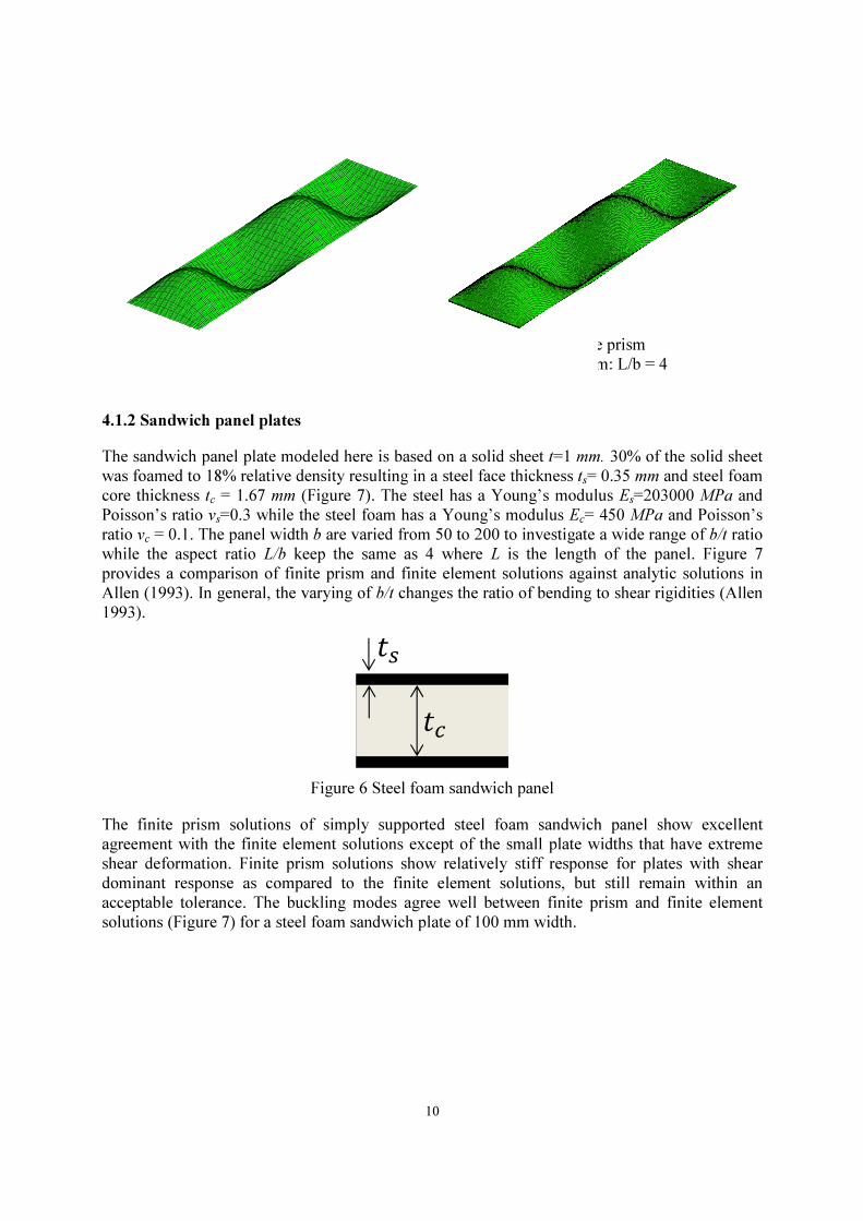
The buckling modes of a plate with L/b =4 are demonstrated in Figure 5 for both finite strip and finite prism solutions. The buckling modes in Figure 5 show excellent agreement.
10
(a) Finite strip (b) Finite prism
Figure 5 Plate buckling modes of finite strip and finite prism: L/b = 4
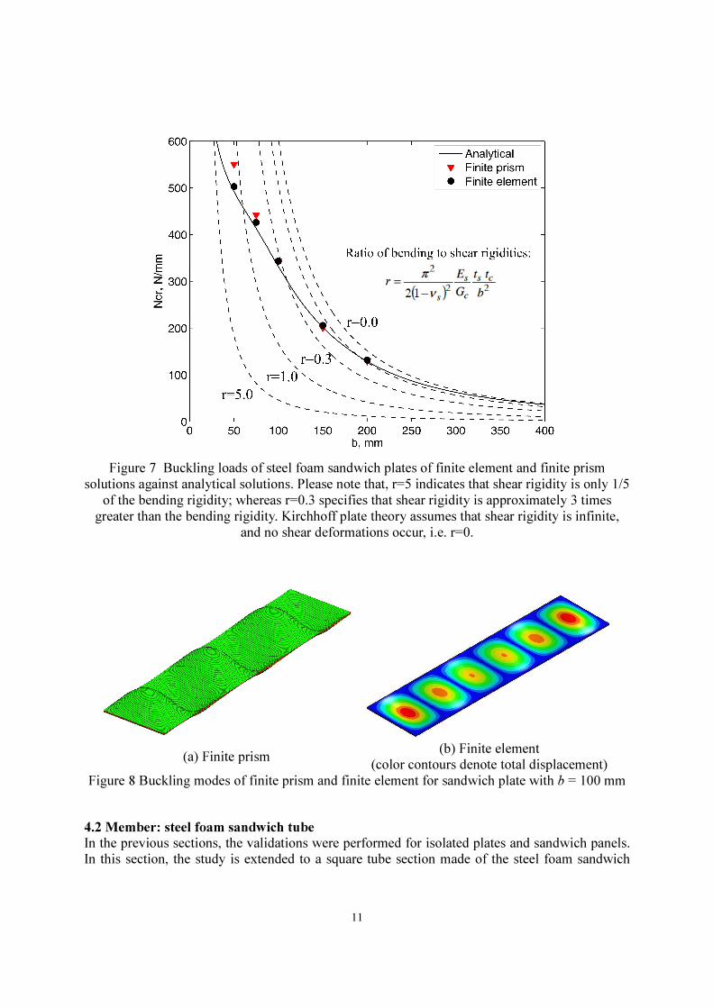
4.1.2 Sandwich panel plates
The sandwich panel plate modeled here is based on a solid sheet t=1 mm. 30% of the solid sheet
was foamed to 18% relative density resulting in a steel face thickness ts= 0.35 mm and steel foam
core thickness tc = 1.67 mm (Figure 7). The steel has a Young’s modulus Es=203000 MPa and
Poisson’s ratio vs=0.3 while the steel foam has a Young’s modulus Ec= 450 MPa and Poisson’s
ratio vc = 0.1. The panel width b are varied from 50 to 200 to investigate a wide range of b/t ratio
while the aspect ratio L/b keep the same as 4 where L is the length of the panel. Figure 7
provides a comparison of finite prism and finite element solutions against analytic solutions in
Allen (1993). In general, the varying of b/t changes the ratio of bending to shear rigidities (Allen
1993).
Figure 6 Steel foam sandwich panel
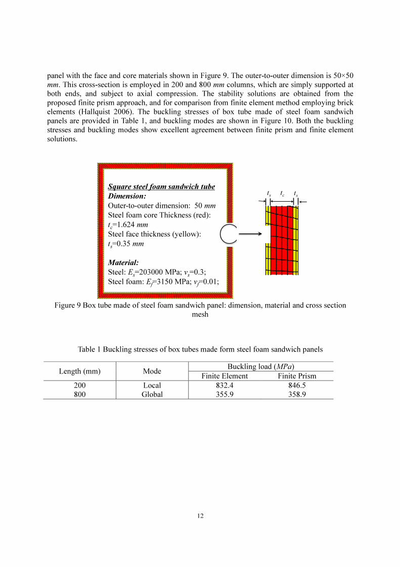
The finite prism solutions of simply supported steel foam sandwich panel show excellent
agreement with the finite element solutions except of the small plate widths that have extreme
shear deformation. Finite prism solutions show relatively stiff response for plates with shear
dominant response as compared to the finite element solutions, but still remain within an
acceptable tolerance. The buckling modes agree well between finite prism and finite element
solutions (Figure 7) for a steel foam sandwich plate of 100 mm width.
11
Figure 7 Buckling loads of steel foam sandwich plates of finite element and finite prism
solutions against analytical solutions. Please note that, r=5 indicates that shear rigidity is only 1/5
of the bending rigidity; whereas r=0.3 specifies that shear rigidity is approximately 3 times
greater than the bending rigidity. Kirchhoff plate theory assumes that shear rigidity is infinite,
and no shear deformations occur, i.e. r=0.
(a) Finite prism (b) Finite element
(color contours denote total displacement)
Figure 8 Buckling modes of finite prism and finite element for sandwich plate with b = 100 mm
4.2 Member: steel foam sandwich tube
In the previous sections, the validations were performed for isolated plates and sandwich panels. In this section, the study is extended to a square tube section made of the steel foam sandwich
12
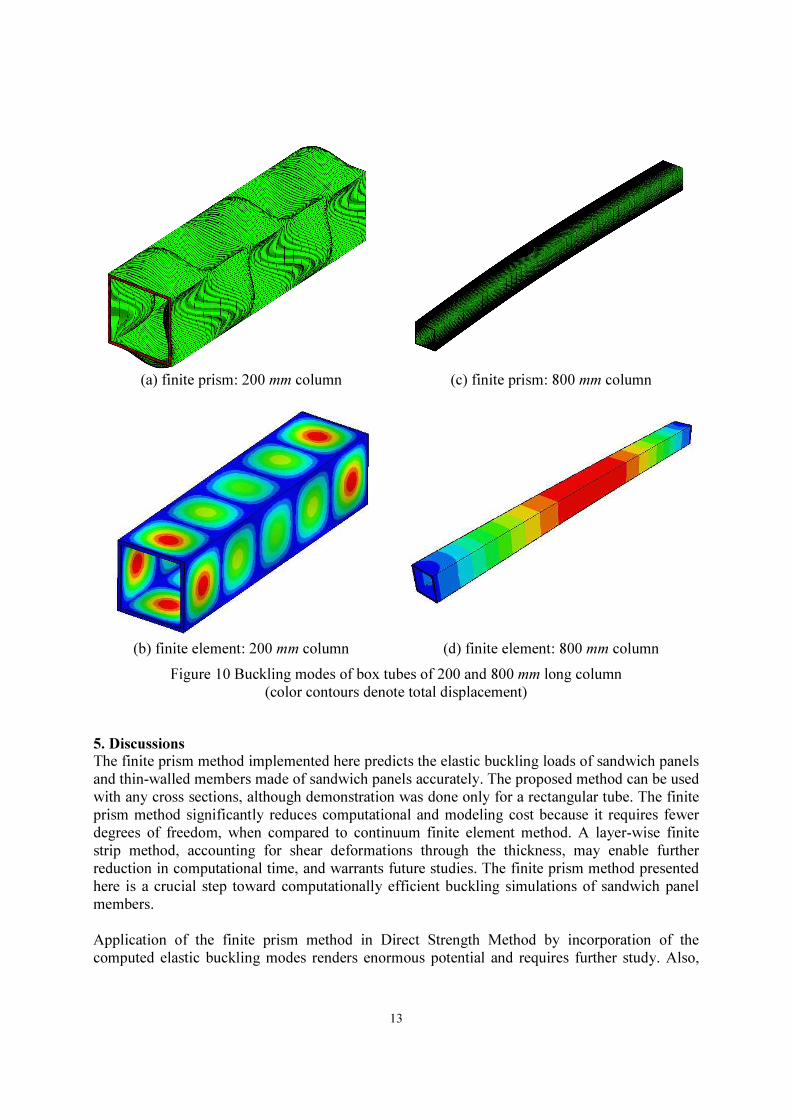
panel with the face and core materials shown in Figure 9. The outer-to-outer dimension is 50×50 mm. This cross-section is employed in 200 and 800 mm columns, which are simply supported at both ends, and subject to axial compression. The stability solutions are obtained from the proposed finite prism approach, and for comparison from finite element method employing brick elements (Hallquist 2006). The buckling stresses of box tube made of steel foam sandwich panels are provided in Table 1, and buckling modes are shown in Figure 10. Both the buckling stresses and buckling modes show excellent agreement between finite prism and finite element solutions.
Figure 9 Box tube made of steel foam sandwich panel: dimension, material and cross section
mesh
Table 1 Buckling stresses of box tubes made form steel foam sandwich panels
Length (mm) Mode Buckling load (MPa)
Finite Element Finite Prism 200 Local 832.4 846.5 800 Global 355.9 358.9
Square steel foam sandwich tube
Dimension:
Outer-to-outer dimension: 50 mm
Steel foam core Thickness (red):
tc=1.624 mm
Steel face thickness (yellow):
ts=0.35 mm
Material:
Steel: Es=203000 MPa; vs=0.3;
Steel foam: Ef=3150 MPa; vf=0.01;
tc t
s t
s
13
(a) finite prism: 200 mm column (c) finite prism: 800 mm column
(b) finite element: 200 mm column (d) finite element: 800 mm column
Figure 10 Buckling modes of box tubes of 200 and 800 mm long column
(color contours denote total displacement)
5. Discussions
The finite prism method implemented here predicts the elastic buckling loads of sandwich panels
and thin-walled members made of sandwich panels accurately. The proposed method can be used
with any cross sections, although demonstration was done only for a rectangular tube. The finite
prism method significantly reduces computational and modeling cost because it requires fewer
degrees of freedom, when compared to continuum finite element method. A layer-wise finite
strip method, accounting for shear deformations through the thickness, may enable further
reduction in computational time, and warrants future studies. The finite prism method presented
here is a crucial step toward computationally efficient buckling simulations of sandwich panel
members.
Application of the finite prism method in Direct Strength Method by incorporation of the
computed elastic buckling modes renders enormous potential and requires further study. Also,
14
future work is needed to the finite prism method and direct strength approach for sandwich members in into the custom version of CUFSM (Li and Schafer 2010). Such custom version will provide engineers and researchers an easy-to-use tool for analysis and design of sandwich members.
6. Conclusions
The finite prism method developed and implemented here provides a straightforward method for calculation of the buckling load of sandwich plates and sandwich members. The finite prism method idealizes a three-dimension problem into a two-dimension formulation with longitudinal fields represented by a specially selected trigonometric shape functions, and enables a full three-dimensional analysis. The longitudinal, end boundary conditions, such as simply supported (S), clamped (C), free (F), and guided (G) are incorporated through the specially selected shape functions. The finite prism method captures the shear deformation through the thickness, in addition to the bending deformation. This is particularly important in sandwich members with deformable steel foam core, which may suffer significant shear deformations. In addition, the finite prism method can capture the composite interaction between the faces and the core of the sandwich panel. The finite prism solutions were validated against finite element solutions employing brick elements in LS-DYNA for both sandwich plates and sandwich members. Although finite prism solution shows slightly stiffer response than finite element solution for edge cases of panels with extreme shear deformations, the finite prism buckling predictions show excellent agreement for the wide spectrum of real-life and practical configurations. The finite prism method is an order to magnitude faster than continuum finite element models. The finite prism method is critical for enabling the direct strength approach for design of thin-walled sandwich members.
References
Allen, Howard G. 1993. Analysis and Design of Structural Sandwich Panels. Pergamon Press. Ashby, M. 2000. Metal Foams : a Design Guide. Boston: Butterworth-Heinemann. Banhart, J., and H.-W. Seeliger. 2008. “Aluminium Foam Sandwich Panels: Manufacture,
Metallurgy and Applications.” Advanced Engineering Materials 10 (9) (September): 793–802. doi:10.1002/adem.200800091.
Bao, H.-Q., and B.-K. Han. 2009. “Transmission Loss of Metallic Foams for the Local Resonance.” In 3rd International Conference on Bioinformatics and Biomedical
Engineering, iCBBE 2009. http://www.scopus.com/inward/record.url?eid=2-s2.0-72749090620&partnerID=40&md5=9404e70afe7de5f7f7dd79a5daa81882.
Bradford, M.A., and M. Azhari. 1995. “Buckling of Plates with Different End Conditions Using the Finite Strip Method.” Computers & Structures 56 (1) (July 3): 75–83. doi:10.1016/0045-7949(94)00528-B.
Cheung, Y. K., and L. G. Tham. 1997. The Finite Strip Method. 1st ed. CRC Press. Coquard, R., D. Rochais, and D. Baillis. 2010. “Conductive and Radiative Heat Transfer in
Ceramic and Metal Foams at Fire Temperatures - Contribution to the Special Issue ‘Materials in Fire’ Guest Editor K. Ghazi Wakili.”
Hallquist, J. 2006. “LS-DYNA: Theory Manual”. Lawrence Software Technology Corporation,Livermore, California.
15
Hipke, T. 2011. “Personal Communication”. Fraunhofer Institute, Chemnitz, Germany. Kardomateas, George A. 2010. “An Elasticity Solution for the Global Buckling of Sandwich
Beams/Wide Panels With Orthotropic Phases.” Journal of Applied Mechanics 77 (2): 021015. doi:10.1115/1.3173758.
Kremer, K, A Liszkiewicz, and J Adkins. 2004. Development of Steel Foam Materials and
Structures, US DOE and AISI Final Report DE-FC36-97ID13554. Newark, DE: Fraunhofer USA – Delaware Center for Manufacturing and Advanced Materials.
Li, Z., and B.W. Schafer. 2009. “Finite Strip Stability Solutions for General Boundary Conditions and the Extension of the Constrained Finite Strip Method.” In Computational
Science, Engineering & Technology Series, ed. B.H.V. Topping, L.F. Costa Neves, and R.C. Barros, 22:103–130. Stirlingshire, UK: Saxe-Coburg Publications. http://www.ctresources.info/csets/chapter.html?id=370.
Li, Z., and B.W. Schafer. 2010. “Buckling Analysis of Cold-formed Steel Members with General Boundary Conditions Using CUFSM: Conventional and Constrained Finite Strip Methods.” In 20th International Specialty Conference on Cold-Formed Steel Structures:
Recent Research and Developments in Cold-Formed Steel Design and Construction. St Louis, MO.
Losito, O., D. Barletta, and V. Dimiccoli. 2010. “A Wide-frequency Model of Metal Foam for Shielding Applications.” IEEE Transactions on Electromagnetic Compatibility 52 (1): 75–81.
Moradi, Mohammadreza, Sanjay R. Arwade, and Benjamin W. Schafer. 2013. “Computational Evaluation of Limit States of Thin-walled Channels Made from Steel Foam.” Thin-
Walled Structures 62 (January): 206–214. doi:10.1016/j.tws.2012.07.007. Neugebauer, R., T. Hipke, J. Hohlfeld, and R. Thümmler. 2005. “Metal Foam as a Combination
of Lightweight Engineering and Damping.” In . Plantema, F. J. 1966. Sandwich Construction: The Bending and Buckling of Sandwich Beams,
Plates and Shells. 1St Edition. John Wiley & Sons Ltd. Schafer, B.W., and S. Ádány. 2006. “Buckling Analysis of Cold-formed Steel Members with
General Boundary Conditions Using CUFSM: Conventional and Constrained Finite Strip Methods.” In Eighteenth International Specialty Conference on Cold-Formed Steel
Structures: Recent Research and Developments in Cold-Formed Steel Design and
Construction. S.t. louis, MO. Smith, B.H., S. Szyniszewski, J.F. Hajjar, B.W. Schafer, and S.R. Arwade. 2012. “Steel Foam
for Structures: A Review of Applications, Manufacturing and Material Properties.” Journal of Constructional Steel Research 71 (April): 1–10. doi:10.1016/j.jcsr.2011.10.028.
Szyniszewski, S., B.H. Smith, J.F. Hajjar, S.R. Arwade, and B.W. Schafer. 2012. “Local Buckling Strength of Steel Foam Sandwich Panels.” Thin-Walled Structures 59 (0) (October): 11–19. doi:10.1016/j.tws.2012.04.014.
Szyniszewski, S., B.H. Smith, V.M. Zeinoddini, J.F. Hajjar, S.R. Arwade, and B.W. Schafer. 2012. “Towards the Design of Cold-formed Steel Foam Sandwich Columns.” In 21st
International Specialty Conference on Cold-Formed Steel Structures, pp.355–372. S.t. louis, MO. http://folio.jhu.edu/faculty_publications/Benjamin%20W._Schafer.
Xu, S., M. Bourham, and A. Rabiei. 2010. “A Novel Ultra-light Structure for Radiation Shielding.” Materials and Design 31 (4): 2140–2146.