Embed Size (px)
Citation preview

IOSR Journal of Mechanical and Civil Engineering (IOSR-JMCE)
e-ISSN: 2278-1684,p-ISSN: 2320-334X, Volume 8, Issue 3 (Sep. - Oct. 2013), PP 08-22 www.iosrjournals.org
www.iosrjournals.org 8 | Page
Finite Element Modeling of a Multi-Storeyed Retrofitted
Reinforced Concrete Frame
Beena Kumari1, Naveen Kwatra
2
(1 Research Scholar, Department of Civil Engineering, Thapar University, Patiala, India)
(2Associate Professor, Department of Civil Engineering, Thapar University, Patiala, India)
Abstract: In the present study, the non-linear response of RC frame using FE modeling under the incremental
loading has been carried out in the first phase of analysis to study the response and load-carrying capacity of a
four storeyed RC frame using non-linear finite element analysis. In the second phase of study an analysis model
for retrofitted RC frame using finite element method using software ATENA is presented. The results obtained
from FE analysis in both cases are compared with the experimental data for four storeyed RC frame tested by
BARC at CPRI. The results from finite element analysis were calculated at the same location as used in
experimental test. The accuracy of the finite element model is assessed by the comparison with experimental
results which are to be in good agreement. The base shear/ displacement curves from finite element analysis
agree well with the experimental results in linear range. The maximum difference in base shear is observed to
be 7.9%.
Key Words: Finite Element modeling, Reinforced concrete frame, fibre reinforced polymer and retrofitted
frame.
I. Introduction In order to evaluate the margin of safety of RC structures against failure an accurate estimation of the
ultimate load is very important and the project of the load-deformation behavior of the structure throughout the
range of elastic and inelastic response is desirable.There are various factors which are accountable for these
deteriorations, such as increasing load, corrosion of steel, earthquake, environmental effects and accidental
impacts on the structure. The increase in scale of modern structures is closely related to the extent and impact of
disaster in terms of human and economical loss in the happening of structural failure [1]. As a result, careful and
detailed structural safety analysis becomes more and more crucial. The purpose of such an analysis is the investigation of the behavior of the structure under all probable loading conditions, both, monotonic and cyclic
The static pushover analysis is becoming a common tool for seismic performance assessment of
existing and new structures. The pushover analysis provides adequate information on seismic demands imposed
by the design ground motion on the structural system and its components. The purpose of pushover analysis is to
evaluate the projected performance of structural systems by estimating performance of a structural system by
estimating its strength and deformation demands in design earthquakes by means of static inelastic analysis, and
comparing these demands to available capacities at the performance levels of interest. The inelastic static
pushover analysis can be viewed as a method for predicting seismic force and deformation demands, which
accounts in an approximate manner for the redistribution of internal forces that no longer can be resisted within
the elastic range of structural behavior [2].
Up-gradation of reinforced concrete structures is required for many different reasons. The concrete may have become structurally inadequate for example, due to deterioration of materials, poor initial design and/or
construction, lack of maintenance, upgrading of design loads or accidental events such as earthquakes. That’s
why repair and rehabilitation has become an increasingly important challenge for the reinforced cement concrete
structures in recent years. The major goals of the retrofitting are to strengthening the retrofitted structures for
life safety and the protection of the structures. The existing deficient structures are retrofitted to improve their
performance in the event of any natural disaster and to avoid large scale damage to life and property. Evaluation
of behaviour of structures after retrofitting is more important.
1.1 Importance and Historical Background of Finite Element Modeling
The complicated analytical modeling of the complex behaviour of reinforced concrete in its non-linear
zone has led engineers in the past to rely heavily on empirical formulas which were derived from numerous
experiments for the design of reinforced concrete structures. The finite element method makes it achievable to take into account the non-linear response. Finite element method of analysis has become a powerful
computational tool with the introduction of digital computers, which allows complex analyses of the nonlinear
response of RC structures to be carried out in a regular mode. Though FEM is useful for obtaining the load

Finite Element Modeling of a Multi-Storeyed Retrofitted Reinforced Concrete Frame
www.iosrjournals.org 9 | Page
deflection behaviour and its crack patterns in various loading conditions but the results of any analytical model
have to be verified by comparing them with experiments in the lab or with full-scale structure [3].
Various researchers have investigated F.E modeling and retrofitting of R.C structures. Kachlakev et al.[3], Amer M. Ibrahim et al. [4], Singhal H.[5], Supaviriyakit et al.[6] and Sanathakumar et al.[7] presented an
analytical analysis model for reinforced concrete beams externally reinforced with fiber reinforced polymer
(FRP) and CFRP laminates using finite elements method adopted. Barbato M. et al.[8] studied the new simple
and efficient two-dimensional frame finite element (FE) able to accurately estimate the load-carrying capacity of
reinforced concrete (RC) beams flexurally strengthened with externally bonded FRP strips and plates. The study
on strengthening of Reinforced Concrete structures by Camata G. et al.[9], Ferracuti et al. [10], Yanga et
al.[11], and Duthinh et al.[12] presented the experimental work for modeling of strengthening of reinforced
concrete beams with externally bonded fibre reinforcement polymers. Mehri et al. [13] worked on the
application of a new high performance fiber reinforced cementitious composite material. The composite can be
applied as a wet mix to the adhesive. The suitability of this technique of member retrofitting to enhance the
strength and ductility of the retrofitted member compared with other methods of local retrofitting, such as steel plates. Perera et al. [14] studied the adhesive connection between FRP and concrete. The test was based on the
beam test, similar to the adherence test for steel reinforcement of concrete. Cardone D. et al. [15] performed an
extensive program of shaking table tests on 1/4-scale three-dimensional R/C frames. It was aimed at evaluating
the usefulness of passive control bracing systems for the seismic retrofit of R/C frames designed for gravity
loads only. Shahawy et al. [16] assessed the effectiveness of external reinforcement in terms of the cracking
moment, maximum moment, deflection, and crack patterns. Four beams (8”x12”x108”) were tested using
minimum steel reinforcement (two ½” diameter bars) and varying the layers of unidirectional CFRP followed by
a non-linear finite element computer model to compare to the results of the experiment.
1.2 Experimental Nonlinear Static Pushover Analysis
Experimentation is an excellent tool for the verification purpose though it is very difficult and un-economical to
perform experiment on full scale structures. The experimentation on full scale real life type structure is the best way to not only study the behavior of the structures under lateral seismic loading but these results can provide
the best database to validate the analytical procedures. In order to bridge this gap between experimental and
analytical data, Reactor Safety Division (RSD), Bhabha Atomic Research Centre (BARC) tested a full–scale
four storeyed structure under lateral monotonically increasing Pushover loads at Central Power Research
Institute (CPRI), Bangalore. The test was conducted under gradually increasing monotonic lateral load in an
inverted triangular pattern till failure [17]. One of the major objectives of this work was to test a real- life
structure under pushover loads. In order to keep the structure as close to reality as possible, no special design for
the structure as such was performed and instead a portion of a real life existing office building was selected.
Thus the structure tested in this work was a replica of a part of an existing office building. The portion
was deliberately selected so that it had certain eccentricities and was un-symmetric in plan. Also the column
sizes and sections were varied along the storey as in the case of original real life structure. Description of Structure: In the present study, non-linear response of RCC control frame using FE Modeling
under the incremental loading has been studied with the intention to investigate the relative importance of
several factors in the non-linear finite element analysis of RCC frames. These include the variation in base-
shear/displacement graph, crack patterns, propagation of the cracks and the crack width on the analytical results.
Geometric and Material Properties The Stress-Strain relationship used is as per I.S.456:2000. The basic material properties used are as follows:
Modulus of Elasticity of steel, Es = 21, 0000 MPa
Modulus of Elasticity of concrete, EC = 22,360.68 MPa
Characteristic strength of concrete, f ck = 20 MPa
Yield stress for steel, fy =415 MPa
Ultimate strain in bending, Ƹcu =0.0035
Model Geometry: The structure analyzed is a four-storeyed, one bay along X-direction and two bays along Y-
direction moment-resisting frame of reinforced concrete with properties as specified above. The concrete floors
are modeled as rigid. The plan of the building is shown in the Fig.1. The bay width, column positions and beams
positions can be seen here.
The load on the structure was applied in an inverted triangular fashion. The ratio of force at “1st floor: 2nd floor:
3rd floor: 4th floor” was kept as “1:2:3:4” as shown in Fig. 1.
The reinforcement details as used in beams and columns are shown in Fig.2.

Finite Element Modeling of a Multi-Storeyed Retrofitted Reinforced Concrete Frame
www.iosrjournals.org 10 | Page
Figure 1 Roof plan, floor plan, sectional elevation and loading pattern
Figure 2 Reinforcement details in beams and columns
II. Finite Element Modeling The program system ATENA offers a variety of material models for different materials and purposes.
The most important material models in ATENA for RCC structure are concrete and reinforcement. These
advanced models take into account all the important aspects of real material behaviour in tension and
compression.
2.1 MODELING OF CONCRETE
Element geometric modeling of concrete has been done using 3D solid brick element with 8 up to 20
nodes in ATENA, shown in Fig.3. 3D solid brick element having three degree of freedom at each node:
translations in the nodal x, y and z directions. This element is capable of plastic deformation, cracking in three
orthogonal directions, and crushing. The most important aspect of this element is the treatment of non-linear
material properties. [18]The process of crack formation can be divided into three stages, Fig.3. The un-cracked
stage is before a tensile strength is reached. The crack formation takes place in the process zone of a potential
crack with decreasing tensile stress on a crack face due to a bridging effect. Finally, after a complete release of
the stress, the crack opening continues without the stress. The tension failure of concrete is characterized by a
regular enhance of cracks, which ultimately disconnect larger parts of the structure. It is usually assumed that cracking formation is a brittle process and that the strength in tension loading direction abruptly goes to zero

Finite Element Modeling of a Multi-Storeyed Retrofitted Reinforced Concrete Frame
www.iosrjournals.org 11 | Page
after such cracks have formed. Therefore, the formation of cracks is certainly one of the most important non-
linear phenomenons, which governs the behaviour of the concrete structures.
Figure 3 Geometry of Brick elements and Stages of Crack Opening [18]
2.2 Modeling of Reinforcement
Geometry and Element Properties of the reinforcement: Modeling of reinforcement in finite element is
much simpler than the modeling of concrete. Reinforcement modeling could be discrete or smeared. In the
present work, a discrete modeling of reinforcement has been done. The reinforcement has been modeled using
bar elements in ATENA. It is a 3D bar element, which has three degrees of freedom at each node; translations in
the nodal x, y and z direction. Bar element is a uni-axial tension-compression element. The stress is assumed to
be uniform over the entire element. This element is capable of plastic deformation, also creep, swelling and
large deflection capabilities are included in the element. Reinforcement can be modeled in two distinct forms:
discrete and smeared. Discrete reinforcement is in form of reinforcing bars. In present study discrete latter approach is used. The bilinear law, elastic-perfectly plastic, is assumed as shown in Figure 4. The initial elastic
part has the elastic modulus of steel Es. The second line represents the plasticity of the steel with hardening and
its slope is the hardening modulus Esh. In case of perfect plasticity Esh =0. Limit strain εL represents limited
ductility of steel.
Figure 4 the bilinear stress-strain law for reinforcement [18]
2.3 Modeling of FRP
Geometry and Element Properties of the FRP: The FRP can be modeled as a 3D shell element (Ahmed shell element) in ATENA. Ahmad shell element used the 20 nodes isoparametric brick element as shown in Figure 5.
The Ahmad shell element implemented in ATENA (Ahmad et al., 1970), can be used to model thin as well as
thick shell or plate structures. In Ahmad shell element every node of element has five degree of freedom, e.g.
three displacements and two rotations in planes normal to mid surface of element. In order to facilitate a simple
connection of this element with other true 3D elements, the five degrees of freedom are transformed into x, y, z
displacement of a top node and x, y displacement of a bottom node degrees of freedom. The two nodes are
located on the normal to mid-surface passing through the original mid-surface element’s node.

Finite Element Modeling of a Multi-Storeyed Retrofitted Reinforced Concrete Frame
www.iosrjournals.org 12 | Page
Figure5. 20 nodes shell element model for FRP [3].
2.4 Summary of Material Properties
2.4.1 Material Properties of RC Frame
Concrete: In ATENA, concrete material is modelled as a 3D nonlinear cementitious2. The physical properties
of 3D nonlinear cementitious2 material are given in “Table2”. The values are calculated as per IS code
456:2000 and remaining are the default values.
Table 2 Material Properties of Concrete Properties Values
Elastic Modulus (Fresh concrete) 22,360 MPa
Poisson Ratio 0.2
Tensile Strength 3.130 Mpa
Compressive Strength 20 Mpa
Specific Material weight 0.024 MN/mE+3
Coefficient of Thermal Expansion 1E-05 1/K
Fixed Crack Model Coefficient 1
Reinforcement Bars: HYSD steel of grade Fe-415 of 28mm, 25mm, 20mm, 16mm and 12mm diameter are
used as main steel while 8mm and 10mm diameter bars are used as shear reinforcement. The properties of these
bars are shown in “Table 3”.
Table 3 Material Properties of Reinforcement Properties Values
Elastic modulus 200000 Mpa
Yield Strength 415 Mpa
Specific Material weight 0.0785 MN/mE+3
Coefficient of Thermal Expansion 1.2E-05 1/K
Steel Plate: The function of the steel plate in the ATENA is for support and for loading. Here, the property of
steel plate is same as the reinforcement bar except its yield strength. The HYSD steel of grade Fe-415 was used
for steel plate.
2.4.2 Material Properties of Retrofitted Frame
Concrete is modeled as 3D Nonlinear Cementitious- 2 material. It is assumed that damage index is 0.6
at final stage. Even after the repair Elastic modulus is assumed to be 0.4 of initial value. The other values of
concrete are incorporated corresponding to 0.4E in the retro-fitted model. The steel reinforcement is also
modeled in the same way as done in case of control frame in previous chapter with one major difference. As the
steel has yielded to its yield point, the value of yield stress is taken 210 MPa instead of 415 MPa. Mbrace
Saturant was used as epoxy in the analysis. The material properties of epoxy are shown in “Table 4”.
Table 4 Material Properties of Epoxy [5] Properties Values
Elastic Modulus 3035 MPa
Poisson Ratio 0.4
Yield Strength 54 Mpa
Specific Material Weight 0.00983 MN/mE+3
Coefficient of Thermal Expansion 5.75E-05 1/K

Finite Element Modeling of a Multi-Storeyed Retrofitted Reinforced Concrete Frame
www.iosrjournals.org 13 | Page
GLASS Fibre Reinforcement Polymer: Mbrace G-sheet EU-900 unidirectional Glass fibre sheet is used in
retrofitting. The properties which are used in the modeling are taken from the Mbrace Product Data, shown in “Table 5”
Table 5. Material Properties of GFRP [5] Properties Values
Strain, stress (0,0); (0.005,390); (0.01,690) MPa
Specific Material Weight 0.026 MN/mE+3
Coefficient of Thermal Expansion 5.E-06 1/K
Elastic Modulus 70 GPa
III. Results And Discussions
Analysis of RC structure has been done in four phases, in first phase FE analysis of RC structure is
performed on ATENA to obtain the deflected shape, Crack pattern and base shear v/s deflection curve and in
second phase compare their results with experimental results as it is already done by “Round Robin Exercise on
Experiment and Analysis of Four Storey Full Scale Reinforced concrete Structure” under Monotonic Push-over
Loads to verify the software results variation, third phase the analysis of RC Retrofitted structure is performed
to obtain the deflected shape, Crack pattern and base shear v/s deflection curve and now in final fourth phase the
comparison in the base shear v/s deflection between experimental control frame, FE control frame and
retrofitted frame has been plotted.
3.1 Non Linear Analysis of RC Structure (First Phase)
Finite element analysis of RCC frame under the static incremental loads has been performed using
ATENA software. The load on the structure has been gradually increased in the steps till failure. When the FE
non linear analysis is completed, the results are shown in third part of the ATENA i.e. Post processing. The
load-deflection values at every step have been recorded, further the crack pattern and cracks propagation at
every step has been studied. The base- shear v/s deflection curves and crack pattern at various floor levels have
been shown in Figure 6 to 13.Subsequently these results are compared with experimental results of Experiment
and Analysis of Four Storey Full Scale Reinforced concrete Structure under Monotonic Push-over Loads’. This
is followed by load deflection curve and the cracking behaviour obtained from the analysis
3.1.1 Base-Shear V/S Deformations at Various Floor Levels
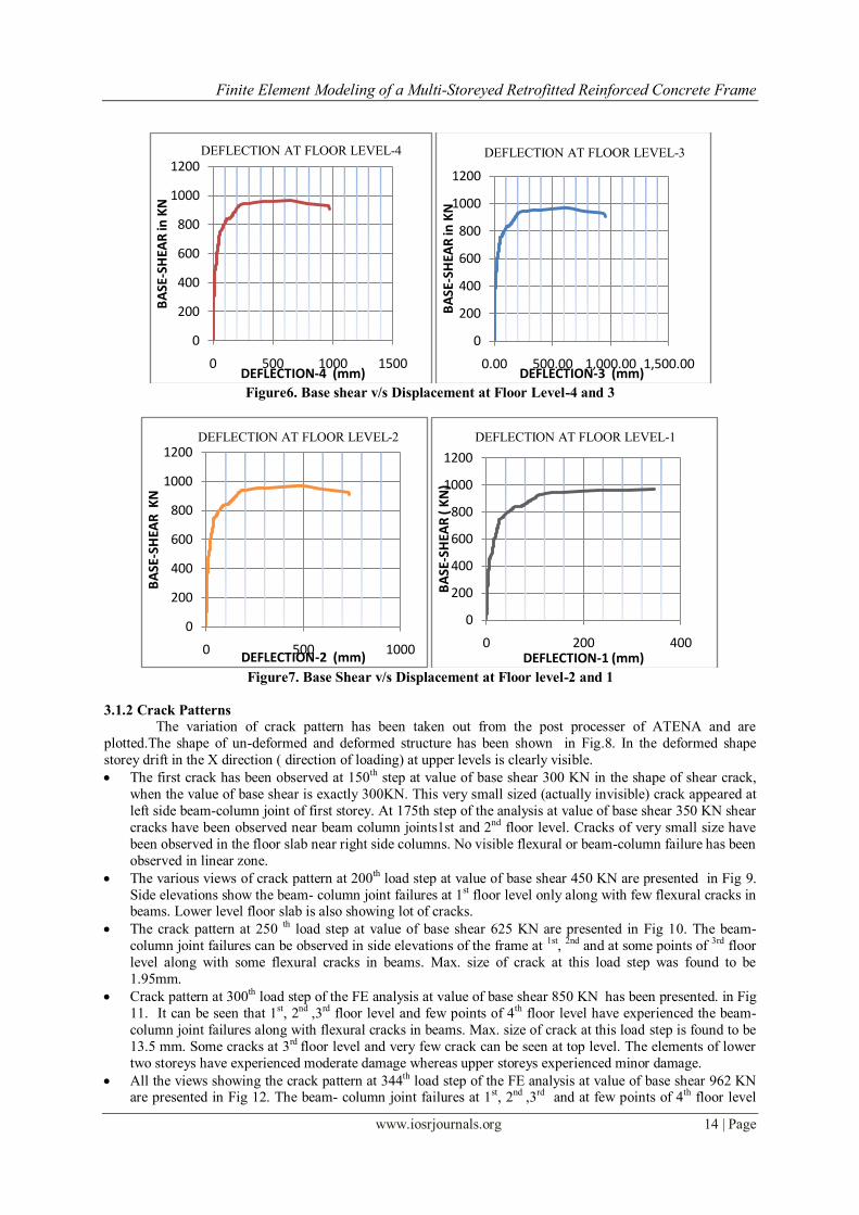
Deflection at the floor level-4 has been plotted in Fig. 6. It can be seen from that the structure behaved linearly
elastic up to the value of base shear around 360 KN. At this point the minor cracks started to get generated at top
floor level. After this point there is a slight curvature in the plot and deflection started increasing with the load
increments. When the base-shear reached to the value of 500 KN, the graph depicted non-linearity in its
behaviour. It is clear from the Figure 6. That at base shear 750 KN, increase in deflection is more with load
increments. At 840 KN base shear deflection has been observed to be 125mm and a rapid increase in
displacement is observed. It has reached to the value of 175mm when base shear is 880 KN. After this point
there is constant increase in deflections and plot has become almost flat after the value of base-shear 927 KN.
Subsequently deflection started increasing without any significant increment in load; it has reached to
the value of 345mm with the base-shear value 952 KN.
Deflection at the floor level-3 has been depicted through Fig. 6. It can be observed from this plot that the load-
deformation behaviour is same as of fourth floor level. The maximum value of deflection has been observed to
be 331mm at the base shear of 952KN.
Deflection at the floor level-1 and level 2 has been depicted through Fig.7. The maximum deflection at base
shear 952 KN has been observed to be 331mm. It has reached to the value of 391mm when base shear is 962
KN, after this it started increasing without any increment in load; it has reached to the value 725 mm. It can be
seen from the Fig. that floor level-1 has experienced the minimum deflection even though the damage
experienced by this floor is maximum. The variation of load-deflection curve is same as per other floor levels.
Finite Element Modeling of a Multi-Storeyed Retrofitted Reinforced Concrete Frame
www.iosrjournals.org 14 | Page
Figure6. Base shear v/s Displacement at Floor Level-4 and 3
Figure7. Base Shear v/s Displacement at Floor level-2 and 1
3.1.2 Crack Patterns
The variation of crack pattern has been taken out from the post processer of ATENA and are
plotted.The shape of un-deformed and deformed structure has been shown in Fig.8. In the deformed shape
storey drift in the X direction ( direction of loading) at upper levels is clearly visible.
The first crack has been observed at 150th step at value of base shear 300 KN in the shape of shear crack,
when the value of base shear is exactly 300KN. This very small sized (actually invisible) crack appeared at
left side beam-column joint of first storey. At 175th step of the analysis at value of base shear 350 KN shear
cracks have been observed near beam column joints1st and 2nd floor level. Cracks of very small size have
been observed in the floor slab near right side columns. No visible flexural or beam-column failure has been
observed in linear zone.
The various views of crack pattern at 200th load step at value of base shear 450 KN are presented in Fig 9.
Side elevations show the beam- column joint failures at 1st floor level only along with few flexural cracks in beams. Lower level floor slab is also showing lot of cracks.
The crack pattern at 250 th load step at value of base shear 625 KN are presented in Fig 10. The beam-
column joint failures can be observed in side elevations of the frame at 1st, 2nd and at some points of 3rd floor
level along with some flexural cracks in beams. Max. size of crack at this load step was found to be
1.95mm.
Crack pattern at 300th load step of the FE analysis at value of base shear 850 KN has been presented. in Fig
11. It can be seen that 1st, 2nd ,3rd floor level and few points of 4th floor level have experienced the beam-
column joint failures along with flexural cracks in beams. Max. size of crack at this load step is found to be
13.5 mm. Some cracks at 3rd floor level and very few crack can be seen at top level. The elements of lower
two storeys have experienced moderate damage whereas upper storeys experienced minor damage.
All the views showing the crack pattern at 344th load step of the FE analysis at value of base shear 962 KN are presented in Fig 12. The beam- column joint failures at 1st, 2nd ,3rd and at few points of 4th floor level
0
200
400
600
800
1000
1200
0 500 1000 1500
BA
SE-S
HEA
R in
KN
DEFLECTION-4 (mm)
DEFLECTION AT FLOOR LEVEL-4
0
200
400
600
800
1000
1200
0.00 500.00 1,000.00 1,500.00
BA
SE-S
HEA
R in
KN
DEFLECTION-3 (mm)
DEFLECTION AT FLOOR LEVEL-3
0
200
400
600
800
1000
1200
0 500 1000
BA
SE-S
HEA
R K
N
DEFLECTION-2 (mm)
DEFLECTION AT FLOOR LEVEL-2
0
200
400
600
800
1000
1200
0 200 400
BA
SE-S
HEA
R (
KN
)
DEFLECTION-1 (mm)
DEFLECTION AT FLOOR LEVEL-1

Finite Element Modeling of a Multi-Storeyed Retrofitted Reinforced Concrete Frame
www.iosrjournals.org 15 | Page
along with flexural cracks in almost all the flexural members can be visualised from different side views All
floor slabs except top level floor slab are showing cracks Some cracks at 3rd floor level and very few crack
have been seen at top level. Major damage has been noticed in elements of lower two storeys whereas 3rd storey experienced moderate damage. The top storey experienced minor damage.
Figure 8. Undeformed and Deformed Shape of RC Frame
Figure 9. Crack Pattern at Step-200 at Base-Shear-450KN
Figure10. Crack Pattern at Step-250 at Base-Shear-625KN
Shear-cracks
BEAM-COLUMN
JOINT FAILURE

Finite Element Modeling of a Multi-Storeyed Retrofitted Reinforced Concrete Frame
www.iosrjournals.org 16 | Page
Figure 11. Crack Pattern at Step-300 at Base-Shear-850KN
Figure 12. Crack Patterns at Step-344 at Base-Shear-962KN
3.1.3 Comparison between the FE Model and the Experimental Results of the Control Frame
Experimental Results of Control Frame [18]
Base shear v/s Floor Displacement (Pushover Curves) the pushover curves as obtained for extreme right side
column (CL20) side are plotted in Fig. 13. As can be seen from the figure the maximum displacement for CL 20
has been obtained as 765mm. The average top drift is therefore equal to round 4% of the total height of the building.
Figure13. Combined Pushover Curve from Experimental Data [18]
0
200
400
600
800
1000
0 200 400 600 800 1000
BA
SE-S
HEA
R (K
N)
DEFLECTION (MM)
BASE SHEAR V/S DEFLECTION
(EXPERIMENTAL)
Dislplacement at 4th floor level
Displacement at 3rd Floor Level
MAX. CRACK SIZE 1.95MM

Finite Element Modeling of a Multi-Storeyed Retrofitted Reinforced Concrete Frame
www.iosrjournals.org 17 | Page
Table7. Comparison of Experimental and FE Model Results of Control RC Frame at Fourth Floor Level SR.NO. EXPERIMENTAL RESULTS
Base Shear(KN) Deflection(mm)
FE MODEL RESULTS
Base Shear(KN) Deflection(mm)
1. 98.1 1 98 2.03
2. 196.2 7 196 4.32
3. 294.3 10 294 6.86
4. 392.4 20 392 10.6
5. 588.6 57 588 28.1
6. 686.7 94 687 49.1
7. 784.8 160 787 84.3
8. 882.9 470 883 177
9. 882.9 765 922 208
10. 392.2 720 952 345
11. -- -- 947 787
12. -- - 927 963
Figure 14. Variation of Base shear v/s Displacement at Floor Level-4 and 3 (Experimental & FE Model)
Figure 15. Variation of Base shear v/s Displacement at Floor Level-2 and 1 (Experimental & FE Model)
3.1.4. Conclusions
The main observations and conclusions drawn are summarized below:
The frame behaved linearly up to a base shear value of 360 KN. At the value of base-shear 500KN, it
depicted non-linearity in its behaviour. Increase in deflection has been observed to be more with base-shear
of 750 KN. At value of base-shear 840 KN, a rapid increase in displacement has been observed. It has
reached the value of 175mm .After this value of base-shear, plastic behaviour has been observed by the
frame as a constant increase in deflection has been observed, after the value of base-shear 927 KN.
Subsequently deflection started increasing without any significant increment in load; it reaches to the value
of 345 mm with the base-shear value 952KN. After this it has kept increasing even at decremental load
steps.
0
200
400
600
800
1000
1200
0 500 1000 1500
BA
SE-S
HEA
R
DEFLECTION-4
BASE-SHEAR V/S DEFLECTION-4
DEF-4 (FE …
0
200
400
600
800
1000
1200
0 500 1000 1500
BA
SE-S
HEA
R (K
N)
DEFLECTION-3( MM)
BASE-SHEAR V/S DEFLECTION-3
DEF-3 (Experimental)
DEF-3 (FE Modal)
0
200
400
600
800
1000
1200
0 500 1000
BA
SE-S
HEA
R (K
N)
DEFLECTION-2 (mm)
BASE-SHEAR V/S DEFLECTION-2
DEF-2 (Experimental)
DEF-2 (FE Modal)
0
200
400
600
800
1000
1200
0 200 400
BA
SE-S
HEA
R (
KN
)
DEFLECTION-1 (mm)
BASE-SHEAR V/S DEFLECTION-1
DEF-1 (Experimental)
DEF-1 (FE Modal)

Finite Element Modeling of a Multi-Storeyed Retrofitted Reinforced Concrete Frame
www.iosrjournals.org 18 | Page
The joints of the structure have displayed rapid degradation and the deflections have increased rapidly in
non- linear zone. Severe damages have occurred at joints at lower floors whereas moderate damages have
been observed in the first and second floors.
The frame has shown variety of failures like beam-column joint failure, flexural failures and shear failures.
Prominent failures shown by FE model are joint failures. Flexural failures have been seen in beams due to
X-directional loading.
After comparing experimental and FE Model base-shear v/s deflection curves of the frame at various floor
levels the FE model results can be said to be reasonably in close agreement with the experimental data from
the full-scale frame test.
The results of FE model of the control frame have found to be higher by 7.9% of the experimental results.
So it can be concluded that FE model push over results holds good with the experimental results though
they are on slightly higher side.
3.2. Results of Retrofitted Frame
3.2.1 Base-Shear V/S Deformations at Various Floor Levels
The load on the structure has been applied in gradual increments till failure. The behaviour of the
elements at every step of load deflection is analyzed with the help of base shear-deflection values at every step,
crack pattern and cracks propagation at every step. From the post-processed data, the values of deflection at
different values of base-shear have been taken and base-shear v/s deflection curves have been plotted in Fig.16
to 18. The behaviour of the structure has been studied at various load levels.
It can be seen from the Figure16 that the retrofitted model has been found to behave totally linearly
elastic up to a value of base shear 250 KN at floor level-4. After this point deflection has been increasing very
slowly with the load increments. It has found to be almost linear till a base shear value of 800 KN, after this
graph has depicted non-linearity in the behaviour of retrofitted frame. After crossing the value of base shear 800
KN, fast increase in the deflection with load increments has been observed. At 850 KN base shear deflection is 10 mm and it has been increasing at fast speed, it crossing 25.4mm when base shear has reached 1300KN. After
this point there is constant increase in deflections without any significant increment in load, graph is almost flat
at 1350KN and deflection has crossed the value of 87.8mm. Base shear v/s deflection curves at floor level-3
depict lesser deflections as compared to top storey deflections as shown in Fig.17. 1st and 2nd floor levels have
experienced very lesser deflections. At base shear of 1000KN structure has been found to suffer severe cracking
at upper floor levels. Cracks in almost every floor have been observed in the FE model.
Results obtained from the analysis are plotted as base shear v/s deflection curves at different floor level are as
given below:
Figure 16. Base shear v/s Displacement at Floor Level-4 and Level-3 3 for Retrofitted Frame
0
200
400
600
800
1000
1200
1400
1600
0 50 100
BA
SE-S
HEA
R (K
N)
DEFLECTION AT FLOOR LEVEL-4 (MM)
BASE-SHEAR V/S DEFLECTION
AT FLOOR LEVEL-4
0
200
400
600
800
1000
1200
1400
0 1 2 3 4
BA
SE-S
HEA
R (K
N)
DEFLECTION AT FLOOR LEVEL -3 (MM)
BASE SHEAR V/S DEFLECTION AT
FLOOR LEVEL-3

Finite Element Modeling of a Multi-Storeyed Retrofitted Reinforced Concrete Frame
www.iosrjournals.org 19 | Page
Figure 17. Base shear v/s Displacement at Floor Level-2 and Level-1 for Retrofitted Frame
3.2.2 Crack Patterns
The variation of crack pattern has been plotted in Figure18 to 20. A discussion on crack pattern has
been presented here.
The crack patterns of the structure at at value of base shear 800 KN has been presented in Figure 18. From
the side elevations, column joint failures at 4st floor level only along with few flexural cracks in beams, can
be seen. Lower level floor slabs have experienced no cracks. Max. size of crack at this load step has been
found to be 0.9mm. This shows that strengthened portion of the frame has experienced no cracking.
The crack patterns at value of base shear 1000 KN are shown in Figure 19. Side elevations show the beam-
column joint failures at 3rd and 4st floor level only along with flexural cracks in beams. Lower level floor
slabs have experienced no cracks. Max. size of crack at this load step has been found to be 1.48 mm.
Mamimum damage has been experienced by column CL-19 at 4th floor level whereas CL-15 was the
member receiving maximum damage 3rd level. Lower level floor slabs experience no cracks. This show that
strengthened portion of the frame has experienced no cracking.
The crack patterns at value of base shear 1150 KN are represented in Figure 20 .The beam- column joint failures at 3rd and 4st floor level can be seen along with flexural cracks have occurred in beams. Lower level
floor slabs experience no cracks. Maximum damage has been experienced by columns CL-15 and CL-19 at
4th floor level whereas CL 15 was the member receiving maximum damage at 3rd level. Lower level floor
slabs experience no cracks. This shows that strengthened portion of the frame has experienced minor
cracking.
It has been observed that frame observed ultimate load at value of base shear 1350 KN. At this level frame
has observed cracks at every level. At this ultimate value of base-shear retrofitted frame has also observed
delamination of FRP wrapping at many places, showing the brittle failure of the frame.
.
Figure 18 Crack Pattern at Step-15 at Base- shear 800 KN
0
200
400
600
800
1000
1200
1400
1600
0 0.05 0.1
BA
SE S
HEA
R (
KN
)
DEFLECTION AT FLOOR LEVEL-1 (MM)
BASE SHEAR V/S DEFLECTION AT
FLOOR LEVEL-1
0
200
400
600
800
1000
1200
1400
0 0.02 0.04 0.06
BA
SE S
HEA
R (K
N)
DEFLECTION AT FLOOR LEVEL-2 (MM)
BASE SHEAR V/S DEFLECTION
AT FLOOR LEVEL-2

Finite Element Modeling of a Multi-Storeyed Retrofitted Reinforced Concrete Frame
www.iosrjournals.org 20 | Page
Figure 19. Crack Pattern at Step-19 at Base-shear 1000 KN
Figure 20. Crack Pattern at Step-22 at Base- shear 1150 KN
3.2.3 COMPARISON BETWEEN THE RESULTS OF CONTROL AND RETROFITTED RC FRAME The comparison in the base shear v/s deflection between experimental control frame, FE control frame and
retrofitted frame has been plotted in Fig. 21. Comparison of cracking patterns between the control and retrofitted
frame has been presented in Fig.22.
The retrofitted model behaved linearly elastic up to the value of base-shear 600KN. The plot has shown
almost negligible curvature up to the base-shear 1250 KN. After this it has observed sudden deflection which indicates frame entering the plastic zone. Fast increase in the value of displacements at fourth floor
level has been observed. The value of deflection at base shear of 1350 KN has been observed as 87mm.
which is very less in comparison with the value of maximum deflection of control frame at ultimate load.
It has been observed from the plot that the retrofitted frame has observed brittle failure, as it has shown
linear behaviour up to base-shear of 1250 KN and shown sudden increase in deflection at almost negligible
increase in load step. The frame has observed total failure at the value of base-shear 1350 KN. This
behaviour indicates decrease in ductility of the frame.
The pattern of cracks has shown strengthened behaviour of retrofitted frame. Lower level floor slabs and
other members have observed minimum cracks opposite to that have been experienced in the case of control
frame.
At ultimate value of base-shear retrofitted frame has observed delamination of FRP wrapping at many places.

Finite Element Modeling of a Multi-Storeyed Retrofitted Reinforced Concrete Frame
www.iosrjournals.org 21 | Page
Figure 21 Comparison Curve of Base shear v/s Displacement at Floor Level-4 (FE Modal, Experimental
& Retrofitted Frame)
Figure 22 Comparison between the control and retrofitted frame
3.2.4 Conclusions The main observations and conclusions drawn are summarized below:
The frame behaved linearly elastic up to a base shear value of around 360 KN. At the value of base-shear
500KN, it depicted non-linearity in its behaviour. Increase in deflection has been observed to be more with
load increments at base-shear of 750 KN showing the elasto-plastic behaviour. At value of base-shear 840
KN, a rapid increase in displacement has been observed. It has reached to the value of 175mm when base
shear is 880 KN. After this value of base-shear, plastic behaviour has been observed by the frame as a
constant increase in deflection has been observed, after the value of base-shear 927 KN. Subsequently
deflection started increasing without any significant increment in load; it reaches to the value of 345 mm
with the base-shear value 952KN. After this it has kept increasing even at decremental load steps.
The joints of the structure have displayed rapid degradation and the inter storey deflections have increased
rapidly in non- linear zone. Severe damages have occurred at joints at lower floors whereas moderate
damages have been observed in the first and second floors. Minor damage has been observed at roof level as shown in figures.
The frame has shown variety of failures like beam-column joint failure, flexural failures and shear failures.
Prominent failures shown by FE model are joint failures. Flexural failures have been seen in beams due to
X-directional loading.
After comparing experimental and FE Model base-shear v/s deflection curves of the frame at various floor
levels the FE model results can be said to be reasonably in close agreement with the experimental data from
the full-scale frame test.
0
200
400
600
800
1000
1200
1400
1600
0 200 400 600 800 1000 1200
BA
SE-S
HEA
R (K
N)
DEFLECTION-4 (MM)
BASE-SHEAR V/S DEFLECTION AT
FLOOR LEVEL-4
DEF-4 (FE Modal)DEF-4 (Experimental)

Finite Element Modeling of a Multi-Storeyed Retrofitted Reinforced Concrete Frame
www.iosrjournals.org 22 | Page
The results of FE model of the control frame have found to be higher by 8% of the experimental results. So
it can be concluded that FE model push over results holds good with the experimental results though they
are on slightly higher side.
The retrofitted model has behaved totally linearly elastic up to a value of base shear 250 KN. It has been
found to be almost linear till a base shear value of 800 KN, after this the non-linearity in the behaviour of
retrofitted frame has been observed. After crossing the value of base shear 800 KN, fast increase in the
deflection with load increments has been observed. After reaching the base-shear of 1300 KN, there is
constant increase in deflections without any significant increment in load and deflection crosses the value of
87.8mm.
Significant increase in the value of base-shear in case of FRP retrofitted FE model has been observed. Base
shear v/s deflection curves at floor level-3 depicts lesser deflections as compared to top storey deflections.
1st and 2nd floor levels have experienced very lesser deflections.
Decrease in ductility has been observed as the frame has experienced failure at lesser values of deflections
at ultimate value of base-shear. Debonding of FRP wrapping has also been observed even at lower value of deflection due to severe failures of beam column joints.
The results of FE model of the retrofitted frame have found to be higher by 29% of the results obtained in
case of control frame.
References [1] A. Habibullah, S. Pyle, Practical Three Dimensional Non-near Static Push-Over Analysis. Structure magazine, winter 1998.
[2] H.G. Kwak, C.F. Fillipou, Finite Element Analysis of Reinforced Concrete Structures Under Monotonic Loading, Structural
Engineering Mechanics and Materials, Report no. UCB/ SEMM-90/14, 1990.
[3] M. Kachlakev, T. Miller, PE. Solomon, P.E; Yim, K. Chansawat, T. Potisuk, Finite Element Modeling of Reinforced Concrete
Structures Strengthened with FRP laminates, Final Report OREGON Department of transportation.2001.
[4] Amer, M. I., Mohammad, M. (2009) , Finite Element Modeling of Reinforced Concrete Strengthened with FRP Laminates,
European Journal of Scientific Research, ISSN 1450-216X, 30 (4), 2009, 526-541.
[5] H. Singhal, Finite Element Modeling of Retrofitted RCC Beams, M.E. Thesis, Thapar University, Patiala.2009.
[6] T.Supaviriyakit, P.Pornpongsaroj, and A. Pimanmas, Finite Element Analysis of FRP Strengthened RC beams, Songklanakarin J.
Science Technology, 26(4), 2004, 497-507.
[7] Santhakumar, R., Chandrasekaran, E. and Dhanaraj, R. ,Analysis of retrofitted reinforced concrete shear beams using carbon fiber
composites, Electronic journal of structural engineering, 4, 2004, 66-74.
[8] M. Barbato, Efficient finite element modeling of reinforced concrete beams retrofitted with fibre reinforced polymers, Journal of
Computers and Structures, 87, 2009, 167-176.N. Pannirselvam, P.N. Raghunath, and K. Suguna, Strength Modeling of Reinforced
Concrete Beam with Externally Bonded Fibre Reinforcement Polymer Reinforcement, American Journal of Engineering and
Applied Sciences, 1(3), 2008, 192-199.
[9] G. Camata, E. Spacone, R. Zarnic, Experimental and non linear Finite Element studies of RC beams strengthened with FRP plates,
Journal of Composites: Part B, 38,2007, 277-288.
[10] B. Ferracuti, B.M. Savoia, C. Mazzotti, A numerical model for FRP-concrete delamination, Journal of Composites, Part B 37, 2006,
356-364.
[11] Z.J. Yang, J.F. Chen, and D. Proverbs, Finite Element Modeling of concrete cover separation failure in FRP plated RC beams,
Construction and Building Materials, Vol 17, 2003, 3-13.
[12] D. Duthinh, and M. Starnes, Strengthening of Reinforced Concrete Beams with Carbon FRP”, Journal of Composites in
Constructions, 2001, 493-498.
[13] M. R. Maheri, Recent Advances in Seismic Retrofit of RC Frames, Asian Journal of Civil Engineering (building and housing) ,6(5)
,2005, 373-391
[14] R. Perera, A. Recuero, A. De Diego., C. Lopez, [Adherence analysis of fiber reinforced polymer strengthened RC beams., Journal
of Computers and Structures, 82, 2004, 1865-1873.
[15] D. Cardone, M. Dolce, F.C. Ponzomm, Experimental behaviour of r/c frames retrofitted with dissipating and recentring braces
,Journal of Earthquake Engineering, 8(3) ,2004, 361-396.
[16] M. Shahawy, M. Arockiasamy, T. Beitelman, and R. Sowrirajan,Reinforced Concrete Rectangular Beams Strengthened with CFRP
Laminates,. Journal of Composites, 27B, 1995, 225-233.
[17] A. Sharma and G.R. Reddy, A report on Round Robin Exercise on experiment and analysis of four storey full scale reinforced
concrete structure under monotonic pushover loads, 2010.
[18] Cervenka Vladimir, Jendele Libor and Cervenka Jan, ATENA theory manual, part 1.
[19] S. M. Ayman, S. Banerjee, Shear enhancement of reinforced concrete beams strengthened with FRP composites laminates” Journal
of Composites: Part B, 38, 2007, 781-793.
[20] A. Goyal, Health Monitoring of Retrofitted Beams by using the Vibration Measurements, M.E. thesis, Thapar University,
Patiala.2007.
[21] O. Benjeddou, M. B. Ouezdou, and A. Bedday, Damaged RC beams repaired by bonding of CFRP laminates, Journal of
Construction and Building Materials, Vol 21, 2007, 1301-1310.
[22] L.V.D. Einde, L. Zhao, F. Seible, Use of FRP Composites in Structural Applications, Construction and Building Materials Vol-17,
2003, 389-403.
[23] R. A Mohammad, C. Christoph, and M. Motavalli, Debonding failure modes of flexural FRP strengthened RC beams, Journal of
Composites: part B, Vol 39, 2007, 826-841.
[24] D. Mostofinejad and S. B. Talaeitaba, Finite Element Modeling of RC connections strengthened with FRP laminates, Iranian
Journal of Science and Technology, Transaction B, Engineering, Vol. 30, 2006, 21-30.