Embed Size (px)
Citation preview
FINITE ELEMENT MICROSTRIP ANTENNA SIMULATOR (FEMAS)
S. Cumhur BASARAN , Yalcin ALBAYRAK, Akdeniz University, Faculty of Engineering, Department of Electrical and Electronics
Campus, 07058 Antalya, TURKEY
[email protected], [email protected]
Abstract In this study, a FEM-based microstrip antenna simulator, namely FEMAS, has been developed. The FEMAS allows analysis and design of three-dimensional microstrip antenna elements and outcomes the related antenna parameters such as input impedance, gain, and radiation pattern. In the paper, the FEM formulation is overviewed and the features of FEMAS are presented. Also, The return loss characteristics of a microstrip antenna achieved by means of FEMAS and Ansoft HFSS are presented.
1. Introduction
Numerical techniques have become a major force in the field of applied electromagnetics. The computing power of computers today has increased to such a large extent that analysis of complex problems is now possible through the use of numerical techniques. Some of the important techniques used are the Finite Element Method (FEM) [1], the Finite Difference Time Domain (FDTD) method [2], the Methods of Moments (MOM) [3] and the Transmission Line Matrix method (TLM). The FEM and the FDTD methods are based on the solution of Maxwell's equations in their differential form (PDE techniques). These techniques are very good at modeling complex, inhomogeneous structures, but they have problems modeling open-region geometries. The MOM solves Maxwell's equations in an integral form (surface integral techniques). This technique is very good at solving open radiation problems but faces problems when it has to deal with complex geometries.
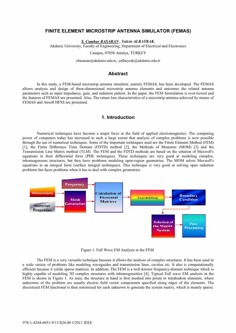
Figure 1. Full Wave EM Analysis in the FEM
The FEM is a very versatile technique because it allows the analysis of complex structures. It has been used in a wide variety of problems like modeling waveguides and transmission lines, cavities etc. It also is computationally efficient because it yields sparse matrices. In addition, The FEM is a well-known frequency-domain technique which is highly capable of modeling 3D complex structures with inhomogeneities [4]. Typical Full wave EM analysis in the FEM is shown in Figure 1. As seen, the structure at hand is first meshed into prism or tetrahedron elements, where unknowns of the problem are usually electric field vector components specified along edges of the elements. The discretized FEM functional is then minimized for each unknown to generate the system matrix, which is mainly sparse.
978-1-4244-6051-9/11/$26.00 ©2011 IEEE
Finally, the FEM system is solved for the edge unknowns via a direct or an iterative solver [4]. In particular, for open (radiation or scattering) problems the computational domain is truncated by an absorbing boundary condition, an artificial absorber or a perfectly-matched layer to simulate the free-space. Alternatively, rather complicated but more accurate truncation can be realized by hybridizing the FEM with the moment method [4].
In this paper, we have introduced a novel microstrip antenna simulator based on the finite element method, namely the in house FEMAS. The simulator is not intended to compete with commercial finite element modeling codes. It does not have a sophisticated mesh generator, graphical output, or unlimited technical support. Its primary strengths is ease-of-use, modest resource requirements, and accurate modeling of three-dimensional microstrip patch antenna configurations over a wide range of frequencies. In addition, it is possible to obtain input impedance and return-loss charecterics and also radiation and gain performances of a microstrip patch antenna. The FEMAS simulator is written in Fotran programming language. Therefore the simulator has no GUI interface and all inputs data are given manuell. We work on visuals and faster version of FEMAS simulator. Our simulation program will become more useful.
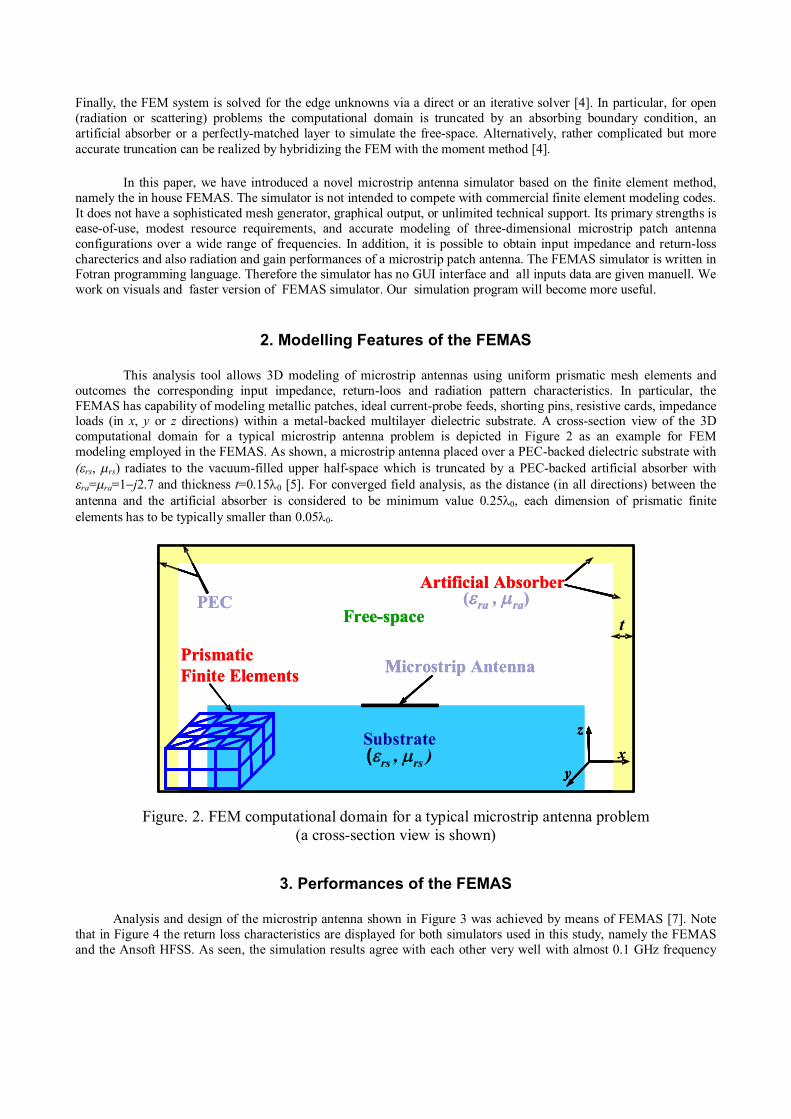
2. Modelling Features of the FEMAS This analysis tool allows 3D modeling of microstrip antennas using uniform prismatic mesh elements and outcomes the corresponding input impedance, return-loos and radiation pattern characteristics. In particular, the FEMAS has capability of modeling metallic patches, ideal current-probe feeds, shorting pins, resistive cards, impedance loads (in x, y or z directions) within a metal-backed multilayer dielectric substrate. A cross-section view of the 3D computational domain for a typical microstrip antenna problem is depicted in Figure 2 as an example for FEM modeling employed in the FEMAS. As shown, a microstrip antenna placed over a PEC-backed dielectric substrate with (rs, rs) radiates to the vacuum-filled upper half-space which is truncated by a PEC-backed artificial absorber with ra=ra=1j2.7 and thickness t=0.150 [5]. For converged field analysis, as the distance (in all directions) between the antenna and the artificial absorber is considered to be minimum value 0.250, each dimension of prismatic finite elements has to be typically smaller than 0.050.
Figure. 2. FEM computational domain for a typical microstrip antenna problem (a cross-section view is shown)
3. Performances of the FEMAS Analysis and design of the microstrip antenna shown in Figure 3 was achieved by means of FEMAS [7]. Note that in Figure 4 the return loss characteristics are displayed for both simulators used in this study, namely the FEMAS and the Ansoft HFSS. As seen, the simulation results agree with each other very well with almost 0.1 GHz frequency
Microstrip Antenna
Free-space
PrismaticFinite Elements
t
y
z
x
PEC
M
Artificial Absorber
t
y
z
xy
z
x(rs , rs )
(ra , ra)
Substrate
Microstrip Antenna
Free-space
PrismaticFinite Elements
t
y
z
xy
z
x
PEC
M
Artificial Absorber
t
y
z
xy
z
x(rs , rs )
(ra , ra)
Substrate
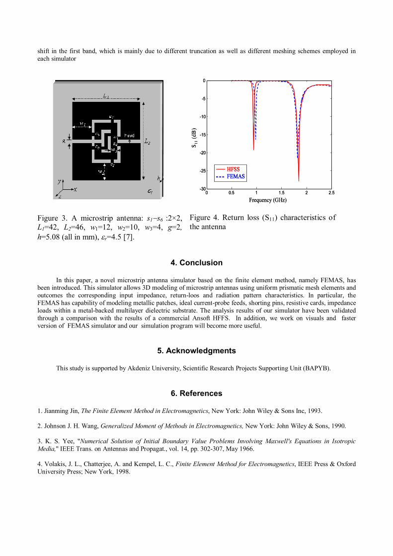
shift in the first band, which is mainly due to different truncation as well as different meshing schemes employed in each simulator
Figure 3. A microstrip antenna: s1s6 :2×2, L1=42, L2=46, w1=12, w2=10, w3=4, g=2, h=5.08 (all in mm), r=4.5 [7].
Figure 4. Return loss (S11) characteristics of the antenna
4. Conclusion
In this paper, a novel microstrip antenna simulator based on the finite element method, namely FEMAS, has been introduced. This simulator allows 3D modeling of microstrip antennas using uniform prismatic mesh elements and outcomes the corresponding input impedance, return-loos and radiation pattern characteristics. In particular, the FEMAS has capability of modeling metallic patches, ideal current-probe feeds, shorting pins, resistive cards, impedance loads within a metal-backed multilayer dielectric substrate. The analysis results of our simulator have been validated through a comparison with the results of a commercial Ansoft HFFS. In addition, we work on visuals and faster version of FEMAS simulator and our simulation program will become more useful.
5. Acknowledgments
This study is supported by Akdeniz University, Scientific Research Projects Supporting Unit (BAPYB).
6. References 1. Jianming Jin, The Finite Element Method in Electromagnetics, New York: John Wiley & Sons Inc, 1993. 2. Johnson J. H. Wang, Generalized Moment of Methods in Electromagnetics, New York: John Wiley & Sons, 1990. 3. K. S. Yee, "Numerical Solution of Initial Boundary Value Problems Involving Maxwell's Equations in Isotropic Media,'' IEEE Trans. on Antennas and Propagat., vol. 14, pp. 302-307, May 1966. 4. Volakis, J. L., Chatterjee, A. and Kempel, L. C., Finite Element Method for Electromagnetics, IEEE Press & Oxford University Press; New York, 1998.
0 0.5 1 1.5 2 2.5-30
-25
-20
-15
-10
-5
0
HFSSFEMAS
Frequency (GHz)S 11
(dB
)0 0.5 1 1.5 2 2.5
-30
-25
-20
-15
-10
-5
0
HFSSFEMASHFSSFEMAS
Frequency (GHz)S 11
(dB
)

5. Ozdemir, T. and Volakis, J. L., A comparative sturdy of an absorber boundary condition and an artificial absorber for truncating finite element mesh, Radio Sci., 29, 255-1263, 1994. 6. Jacobs, D. A. H., A generalization of the conjugate gradient method to solve complex systems, IMA J. Numerical Anal., 6, 447-452,1986. 7. Basaran, S. C., GSM/DCS microstrip antenna design using finite element method, International Journal of Engineering & Applied Science, 2(1), 44-53, 2009.