Embed Size (px)
Citation preview
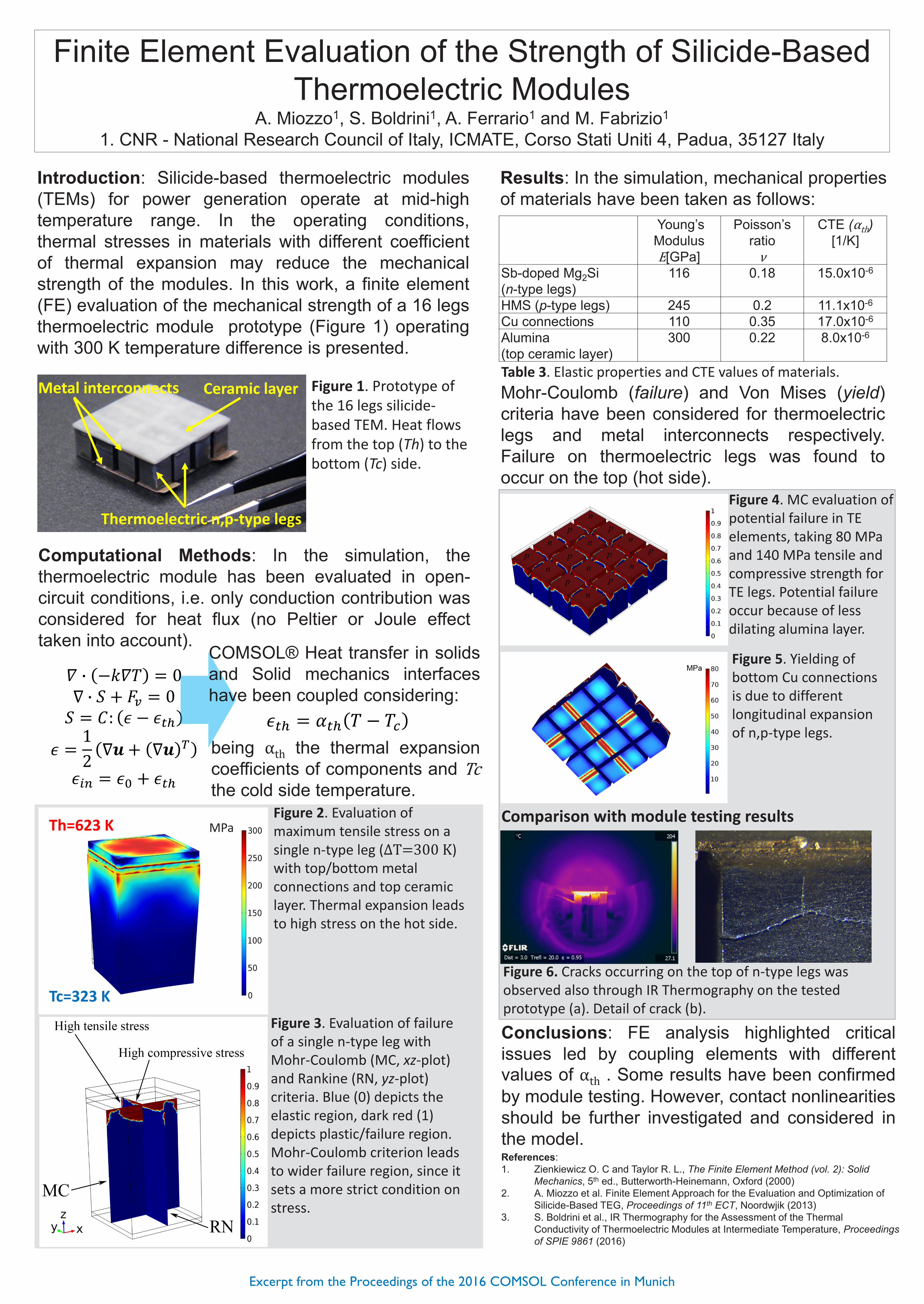
Finite Element Evaluation of the Strength of Silicide-Based Thermoelectric Modules
A. Miozzo1, S. Boldrini1, A. Ferrario1 and M. Fabrizio1
1. CNR - National Research Council of Italy, ICMATE, Corso Stati Uniti 4, Padua, 35127 Italy
Introduction: Silicide-based thermoelectric modules(TEMs) for power generation operate at mid-hightemperature range. In the operating conditions,thermal stresses in materials with different coefficientof thermal expansion may reduce the mechanicalstrength of the modules. In this work, a finite element(FE) evaluation of the mechanical strength of a 16 legsthermoelectric module prototype (Figure 1) operatingwith 300 K temperature difference is presented.
Computational Methods: In the simulation, thethermoelectric module has been evaluated in open-circuit conditions, i.e. only conduction contribution wasconsidered for heat flux (no Peltier or Joule effecttaken into account).
Results: In the simulation, mechanical propertiesof materials have been taken as follows:
References:1. Zienkiewicz O. C and Taylor R. L., The Finite Element Method (vol. 2): Solid
Mechanics, 5th ed., Butterworth-Heinemann, Oxford (2000)2. A. Miozzo et al. Finite Element Approach for the Evaluation and Optimization of
Silicide-Based TEG, Proceedings of 11th ECT, Noordwjik (2013) 3. S. Boldrini et al., IR Thermography for the Assessment of the Thermal
Conductivity of Thermoelectric Modules at Intermediate Temperature, Proceedings of SPIE 9861 (2016)
Figure 1. Prototype of the 16 legs silicide-based TEM. Heat flows from the top (Th) to the bottom (Tc) side.
COMSOL® Heat transfer in solidsand Solid mechanics interfaceshave been coupled considering:
Mohr-Coulomb (failure) and Von Mises (yield)criteria have been considered for thermoelectriclegs and metal interconnects respectively.Failure on thermoelectric legs was found tooccur on the top (hot side).
Thermoelectric n,p-type legs
Metal interconnects Ceramic layer
Young’s Modulus
[GPa]
Poisson’s ratio
ν
CTE (α )[1/K]
Sb-doped Mg2Si(n-type legs)
116 0.18 15.0x10⁻⁶
HMS (p-type legs) 245 0.2 11.1x10⁻⁶
Cu connections 110 0.35 17.0x10⁻⁶
Alumina(top ceramic layer)
300 0.22 8.0x10⁻⁶
Figure 4. MC evaluation of potential failure in TE elements, taking 80 MPa and 140 MPa tensile and compressive strength for TE legs. Potential failure occur because of less dilating alumina layer.
Figure 5. Yielding of bottom Cu connections is due to different longitudinal expansion of n,p-type legs.
Figure 6. Cracks occurring on the top of n-type legs was observed also through IR Thermography on the tested prototype (a). Detail of crack (b).
Comparison with module testing results
Conclusions: FE analysis highlighted criticalissues led by coupling elements with differentvalues of α . Some results have been confirmedby module testing. However, contact nonlinearitiesshould be further investigated and considered inthe model.
being α the thermal expansioncoefficients of components andthe cold side temperature.
Tc=323 K
Th=623 K
Figure 3. Evaluation of failure of a single n-type leg with Mohr-Coulomb (MC, xz-plot) and Rankine (RN, yz-plot) criteria. Blue (0) depicts the elastic region, dark red (1) depicts plastic/failure region. Mohr-Coulomb criterion leads to wider failure region, since it sets a more strict condition on stress.
Figure 2. Evaluation of maximum tensile stress on a single n-type leg (∆T=300 K) with top/bottom metal connections and top ceramic layer. Thermal expansion leads to high stress on the hot side.
MPa
Table 3. Elastic properties and CTE values of materials.
Excerpt from the Proceedings of the 2016 COMSOL Conference in Munich