Embed Size (px)
Citation preview
Jurnal Tribologi 22 (2019) 1-17
Received 29 June 2018; received in revised form 28 August 2018; accepted 12 January 2019. To cite this article: Kadam et al. (2019). Finite element analysis on nano-indentation behavior in columnar 7YSZ EB-PVD thermal barrier coatings. Jurnal Tribologi 22, pp.1-17.
© 2019 Malaysian Tribology Society (MYTRIBOS). All rights reserved.
Finite element analysis on nano-indentation behavior in columnar 7YSZ EB-PVD thermal barrier coatings Nikhil Rajendra Kadam *, Karthikeyan, G., Dhananjay Kulkarni
Birla Institute of Technology & Science, Pilani, K.K. Birla Goa Campus, NH-17B, Zuarinagar, 403726 Goa, INDIA. *Corresponding author: [email protected]
KEYWORDS ABSTRACT
Thermal barrier coatings Nano-indentation Finite element method Columnar microstructure Kink bands Shear bands
Nano-indentation is an important technique to characterize elastic/plastic deformation of Thermal Barrier Coatings (TBCs). In this paper, the nanoindentation of 7YSZ TBC with columnar grain structure is performed using Finite Element Method (FEM) based on a nonlinear contact model. An indentation model subjected to a quasi-static with rigid indenter and the deformable surface is considered with contact mechanics approach. The FE simulation compares the effect of different indenter shapes (spherical, flat and conical) with a variation of contact friction, columnar friction, and the ratio of columnar gap to the width on elastic/plastic, load-displacement response in detailed. The simulation results showed the clear difference in the load-displacement response for different indenter shapes with a variation of parameters. In all cases, the force acting on the indenter gradually increases with an increase in impression depth. For flat indenter, we observed the largest deformation value resulting in the largest force acting on the indenter compared to spherical and conical ones. Also, the indenter shapes strongly affect the orientation and formation of kink and shear bands. The flat indenter results in a more localized pattern of von-mises stress and compressive stress distribution leading to a larger force for the same magnitude of the displacement.
Jurnal Tribologi 22 (2019) 1-17
2
NOMENCLATURE TBCs Thermal Barrier Coatings EB-PVD Electron Beam-Physical Vapour Deposition APS Atmospheric plasma spray COFI Contact friction COFC Columnar friction R Ratio of columnar gap to the width Cw Columnar grain width (µm) Cg Columnar gap (µm) YSZ Yttria stabilized zirconia FEM Finite element method FEA Finite element analysis 3D Three dimensional 2D Two dimensional D Radius of spherical indenter (µm) Θ Inclination angle of flat and conical indenter (º) l The overall length of columnar grains (µm) ρ Density (Kg/m3) E Young’s modulus (GPa) ν Poisson ratio σy Yield stress (MPa) σMises Von-mises stress (MPa) σ1, σ2, σ3 Principle stress (MPa) δ Impression depth (µm) 1.0 INTRODUCTION
Thermal Barrier Coatings (TBCs) are an advanced coating material which plays a vital role to protect gas turbine and aero engines allowing them to operate at high inlet gas temperatures. In the 1960s, first TBCs were successfully applied to exhaust nozzle of X-15 rocket (Miller, 1987). Later in the 1970s and by 1980s, TBCs was commercially applied to various hot component surfaces of gas turbine and aero engines (Miller, 1995). Yttria Stabilized Zirconia (YSZ) is the most common material applied as TBCs onto the surface component due to its low thermal conductivity and superior mechanical properties.
The TBC system is the multilayer structure consisting of superalloy substrate and metallic bond coat such as NiCoCrAlY in order to provide mechanical bonding, reduce thermal expansion coefficient mismatch and protection of substrate from high-temperature erratic environment conditions. The final layer is the ceramic top coat which provides actual thermal barrier forming a thermal insulation layer and protects the component surface against high gas temperatures and erratic environments (Karlsson, 2007; Zhang et al., 2016). The most common deposition process to deposit TBC is Electron-Beam Physical Vapor Deposition (EB-PVD) and Atmospheric Plasma Spray (APS) (Schulz et al., 2003). The EB-PVD TBC consists of columnar grain structure and APS consists of splat layer structure. But EB-PVD is superior because it offers numerous advantages such as uniform coating thickness, smooth coating surface finish, strong adhesion, high strain tolerance, better oxidation and corrosion resistance resulting better TBC lifespan. The continued
Jurnal Tribologi 22 (2019) 1-17
3
development in the field of TBCs is envisioned as prime reliant to increase in high inlet gas temperatures and thrust-to-weight ratio for the improvement in performance of advanced gas turbine and aero engines (Levi, 2004). The TBCs are capable of providing temperature drop and allowing the component surface to operate even at higher inlet gas temperatures (Gong et al., 2005; Myoung et al., 2013).
Nano-indentation is an important method to characterize elastic/plastic deformation behavior of TBCs as the physical investigation is very complicated with many mechanical properties and can’t reflect the real behavior during its functioning. The Finite Element (FE) simulation can help to study complex indentation problems for optimizing the coating microstructure and thickness to improve the properties of TBCs under specific conditions. (Lugscheider et al., 2001) used an indentation method to study mechanical properties of zirconia TBCs produced by EB-PVD. In columnar structure TBC, the grain and grain boundaries have different mechanical properties in perpendicular and parallel direction. (Panich and Sun, 2004) studied nanoindentation of soft coating on a harder substrate and reported the relationship between impression depth and yield strength ratio with a radius of indenter tip. (Chen et al., 2004) studied the plastic deformation behavior and densification of columnar TBC with columnar distortions caused by impression using FEM. The relationship was found between the deformation behavior and constituent properties such as column width and friction coefficients. A similar investigation is carried out by (Wang et al., 2014) to study the effect of indenter shapes on the elastic/plastic behavior of columnar grains and inner sub-grains under micro-indentation. The results showed that both the friction coefficient plays an important role in affecting the band formation and deformation behavior of columnar TBCs. (Karthik et al., 2012) studied ball indentation process to characterize mechanical properties based on the deformable material under spherical indenter. The influence of contact friction on a load-displacement curve with strain hardening exponent and indentation depth is used to study pile-up/sink-in phenomenon using FEM. (Zhao et al., 2006) proposed the 3D-FEA technique to determine residual stresses, elastic modulus, and yield stress of linear elastic, perfectly plastic bulk material from the load-displacement curve with conical indentation. (Vasinonta and Beuth, 2001) studied the interfacial toughness in TBCs using indentation technique developed by FEM. The study is conducted by taking into account the deformation of the bond coat, substrate, indenter shape, specimen size and friction coefficients in the structure. It is found that the friction coefficients and specimen size shows the significant effect on the results obtained by indentation model on coating adhesion. The toughness plot characterizes the loss of coating adhesion with exposure to high temperature. (Zisis and Fleck, 2010) studied FE model to determine the erosion mechanism using elastic /plastic indentation of columnar TBCs under spherical indenter. The geometry and the material parameters were varied in order to find the level of induced tensile stress which can lead to cracking phenomenon in the coating structure. (Keshavarz et al., 2013) studied the mechanical properties with respect to adhesion of the top coat zirconia with the interfacial bond coat using indentation technique. The relationship is found between the hardness of the coating and the substrate preheat temperature. With higher substrate temperature, the columnar grain structure becomes coarser leading to weaker grain boundaries. The increase in deposition temperature results in increasing hardness of the coating structure. (Capitanu et al., 2018) investigated the failure mechanism and coating adhesion using single pass single indenter scratch test to avoid the occurrence of fatigue phenomenon in case of multi-pass single indenter with different coating thickness. It was found that the increase in coating thickness results in improvement in the hardness value of the coating structure. On the
Jurnal Tribologi 22 (2019) 1-17
4
other hand, the pile-up and sink-in phenomenon are reduced with the improvement in the hardness of the coating.
The objective of this paper is to simulate nano-indentation process to characterize the mechanical properties such as stress distribution, friction coefficients and elastic/plastic deformation behavior on columnar structure 7YSZ TBCs. The columnar grain structure TBC produced with the EB-PVD process is used to study the indentation process with different indenter shapes such as spherical, flat and conical shape indenters. The nanoindentation process will help to find the effects of varying ratio of columnar gap to the width, contact friction and columnar friction on deformation behavior and formation of kink and shear bands in the columnar structure. 2.0 FINITE ELEMENT ANALYSIS AND MODEL DESCRIPTION
To simplify FE analysis, the 3D model is reduced to 2D axsymmetrical, in order to reduce computational time and model size. The 2D axisymmetric indentation model for TBC produce with the EB-PVD process for nano-indentation incorporating the commercial finite element software Abaqus 2016 version is used.
2.1 Geometric Model and Material Properties
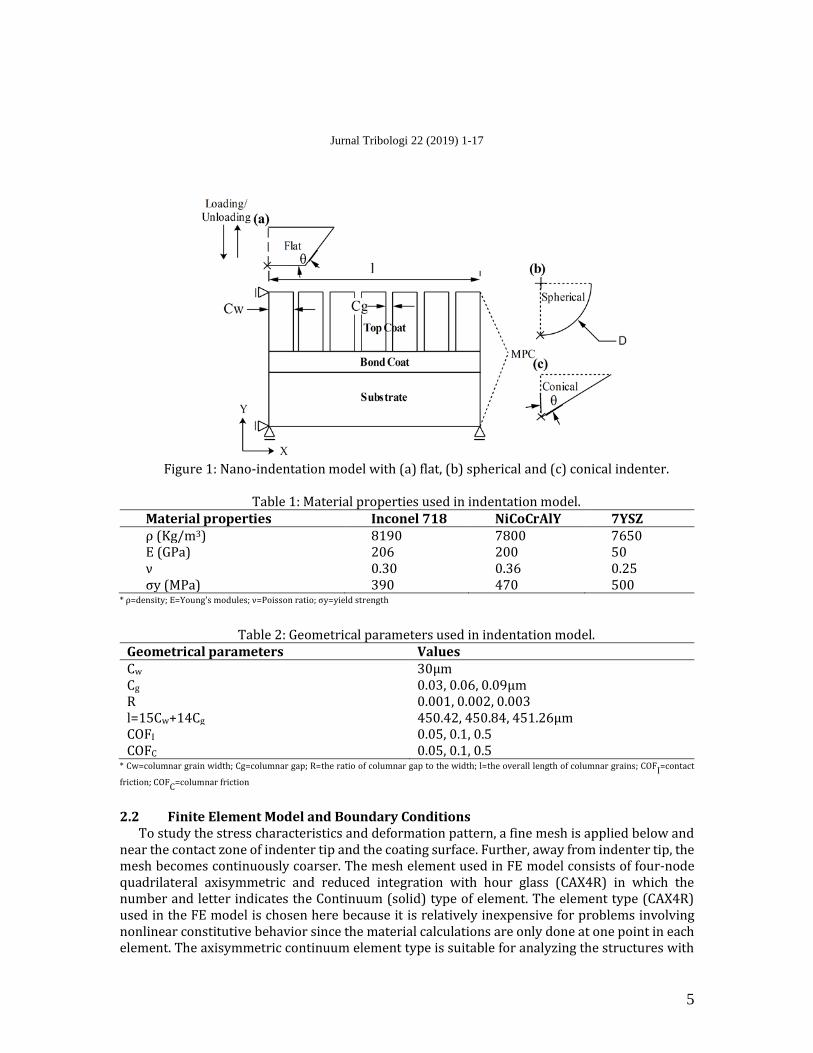
The 2D axisymmetric contact model for TBC structure composed of three layers, namely Inconel 718 nickel-based superalloy substrate with a thickness of 3mm, NiCoCrAlY metallic bond coat with 100μm and 7YSZ ceramic top coat with 250μm is developed and implemented for nano-indentation as shown in Figure 1. The material properties and geometrical parameters used in indentation model are listed in Table 1 and Table 2, respectively. The following assumptions are considered for the simulation steps: (a) The multilayers structure of TBC is assumed to be homogeneous and isotropic, (b) The material properties included in the indentation model for the ceramic top coat is considered to be linear elastic, while bond coat and substrate was considered to be elastic/plastic, and (c) The 3D model is reduced to 2D axisymmetric contact model. Before deformation, the columnar grains are assumed to be straight and parallel with columnar grain width (Cw) and varying columnar gap (Cg).
Different types of indenter shapes such as spherical, flat and conical were considered for the impression on the TBC structure to study the deformation behavior of the columnar structure. As indentation model is 2D axisymmetric, half indenter geometry is considered which is assumed as a rigid body. The indenter is to be considered as master surface as it is rigid body and coating surface is to be considered as slave surface to establish the contact couple between the indenter and the coating. Usually, the indenter has the high elastic modulus and low Poisson's ratio compared to the superalloy substrate and the coating material, hence it is to be considered as an analytical rigid body in order to save computational time. Consider D as the diameter of spherical indenter as 400μm and θ as the inclination angle of flat as 135° and conical indenter at 70.3° as represented in Figure 1. The reference key point is considered on the indenter tip in order to set and apply displacement to the indenter. The simulation is carried out in two steps i.e. loading and unloading with the displacement of 50µm gradually applied to the reference key point of the indenter tip. The coefficient between the indenter tip and columnar top coat is considered to be contact friction (COFI), and the contact between the adjacent columnar grains is considered to be columnar friction (COFC).
Jurnal Tribologi 22 (2019) 1-17
5
Figure 1: Nano-indentation model with (a) flat, (b) spherical and (c) conical indenter.
Table 1: Material properties used in indentation model.
Material properties Inconel 718 NiCoCrAlY 7YSZ ρ (Kg/m3) 8190 7800 7650 E (GPa) 206 200 50 ν 0.30 0.36 0.25 σy (MPa) 390 470 500
* ρ=density; E=Young's modules; ν=Poisson ratio; σy=yield strength
Table 2: Geometrical parameters used in indentation model.
Geometrical parameters Values Cw 30μm Cg 0.03, 0.06, 0.09μm R 0.001, 0.002, 0.003 l=15Cw+14Cg 450.42, 450.84, 451.26μm COFI 0.05, 0.1, 0.5 COFC 0.05, 0.1, 0.5
* Cw=columnar grain width; Cg=columnar gap; R=the ratio of columnar gap to the width; l=the overall length of columnar grains; COFI=contact
friction; COFC
=columnar friction
2.2 Finite Element Model and Boundary Conditions
To study the stress characteristics and deformation pattern, a fine mesh is applied below and near the contact zone of indenter tip and the coating surface. Further, away from indenter tip, the mesh becomes continuously coarser. The mesh element used in FE model consists of four-node quadrilateral axisymmetric and reduced integration with hour glass (CAX4R) in which the number and letter indicates the Continuum (solid) type of element. The element type (CAX4R) used in the FE model is chosen here because it is relatively inexpensive for problems involving nonlinear constitutive behavior since the material calculations are only done at one point in each element. The axisymmetric continuum element type is suitable for analyzing the structures with

Jurnal Tribologi 22 (2019) 1-17
6
axisymmetric geometry subjected to axisymmetric loading. Also, the continuum element type can be used to build the model of nearly any shape subjected to any loading condition. The process of indentation is simulated in two steps i.e. loading and unloading. In loading step, the full displacement is given to the reference tip of the indenter tip in the –ve y direction till the reaction force reach to the maximum value to obtain the maximum plastic deformation in the columnar coating. Second, in unloading step, the indenter is returned to its original position by applying +ve y direction displacement where the elastic recovery in the coating occurs. The following boundary conditions are applied to the indentation model as shown in Figure 1: (a) The bottom of the substrate is constrained at Uy=0, (b) The centerline of TBC structure i.e. the axis of symmetry is constrained at Ux=0, and (c) The periodic boundary conditions with Multi-Point Couple (MPC) and tie constraint is applied on the right side of TBC model for the same displacement along the horizontal direction. 3.0 RESULTS AND DISCUSSION
In this work, an effect of different indenter shapes like spherical, flat and conical indenters is studied with gradually applied impression depth of 50µm. The results obtained are based on the variation of contact friction (COFI) at an interface between indenter and the coated surface, columnar friction (COFC) and the ratio of columnar gap to the columnar width (R) for different cases. The influence of both variations of contact frictions with a columnar gap (Cg=0.03, 0.06 and 0.09) on the deformation of columnar grain structure is explored using three types of contact values i.e. frictionless contact with 0.05, sliding contact with 0.1, and sticking contact with 0.5 (Chen et al., 2004). The results obtained are discussed in the following categories such as load vs. displacement behavior, von-mises stress, shear stress, and deformation behavior for different cases. 3.1 Load vs. Displacement Behavior
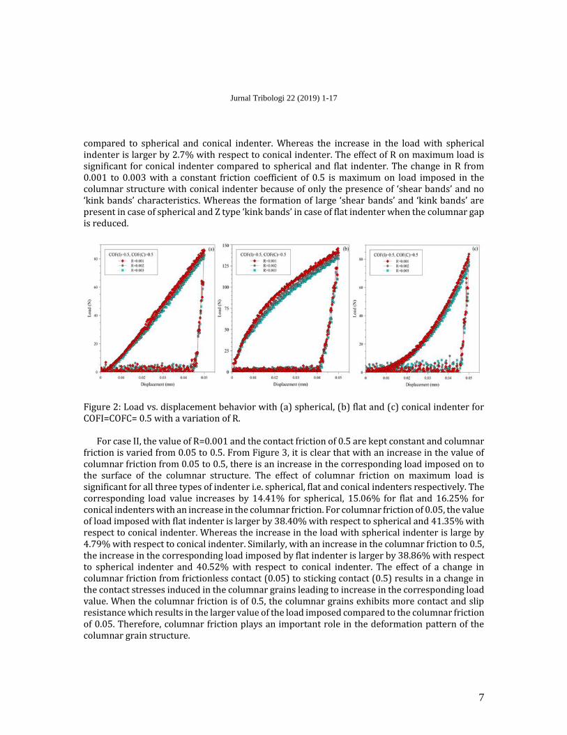
Figure 2-4 shows the load vs. displacement behavior on the coated surface with spherical, flat and conical indentation respectively for different cases. The study has been conducted by keeping two variables constant at their specific values and the effect of the third variable is studied. In load vs. displacement behavior, case I represents both friction coefficients are kept constant at 0.5 with variation of R from 0.001 to 0.003, case II represents R of 0.001 and contact friction of 0.5 to be constant with variation of columnar friction from 0.05 to 0.5, and case III represents R of 0.001 and columnar friction of 0.5 to be constant with variation of contact friction from 0.05 to 0.5 respectively.
For the case I, both friction coefficients are kept constant at 0.5 and variation of the ratio of columnar gap to the width from 0.001 to 0.003 as shown in Figure 2 for different types of indenter shape. From Figure 2, it is clear that as the ratio of columnar gap to the width is increased from 0.001 to 0.003, there is a decrease in the maximum load imposed on the columnar structure. For the larger columnar gap, the contact stresses will decrease for the same impression depth which results in a decrease in value of the corresponding load. The corresponding load value decreases by 4.17% for spherical indenter, 4.88% for flat indenter and 9.46% for conical indenter with an increase in the ratio of columnar gap to the width from 0.001 to 0.003. For R=0.001, the value of load imposed on the columnar structure with flat indenter is larger by 38.87% with respect to spherical indenter and by 40.52% with respect to conical indenter. The maximum load value imposed with flat indenter is larger because of more contact area with columnar grain structure
Jurnal Tribologi 22 (2019) 1-17
7
compared to spherical and conical indenter. Whereas the increase in the load with spherical indenter is larger by 2.7% with respect to conical indenter. The effect of R on maximum load is significant for conical indenter compared to spherical and flat indenter. The change in R from 0.001 to 0.003 with a constant friction coefficient of 0.5 is maximum on load imposed in the columnar structure with conical indenter because of only the presence of ‘shear bands’ and no ‘kink bands’ characteristics. Whereas the formation of large ‘shear bands’ and ‘kink bands’ are present in case of spherical and Z type ‘kink bands’ in case of flat indenter when the columnar gap is reduced.
Figure 2: Load vs. displacement behavior with (a) spherical, (b) flat and (c) conical indenter for COFI=COFC= 0.5 with a variation of R.
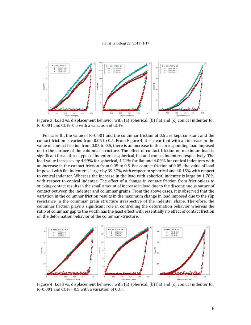
For case II, the value of R=0.001 and the contact friction of 0.5 are kept constant and columnar friction is varied from 0.05 to 0.5. From Figure 3, it is clear that with an increase in the value of columnar friction from 0.05 to 0.5, there is an increase in the corresponding load imposed on to the surface of the columnar structure. The effect of columnar friction on maximum load is significant for all three types of indenter i.e. spherical, flat and conical indenters respectively. The corresponding load value increases by 14.41% for spherical, 15.06% for flat and 16.25% for conical indenters with an increase in the columnar friction. For columnar friction of 0.05, the value of load imposed with flat indenter is larger by 38.40% with respect to spherical and 41.35% with respect to conical indenter. Whereas the increase in the load with spherical indenter is large by 4.79% with respect to conical indenter. Similarly, with an increase in the columnar friction to 0.5, the increase in the corresponding load imposed by flat indenter is larger by 38.86% with respect to spherical indenter and 40.52% with respect to conical indenter. The effect of a change in columnar friction from frictionless contact (0.05) to sticking contact (0.5) results in a change in the contact stresses induced in the columnar grains leading to increase in the corresponding load value. When the columnar friction is of 0.5, the columnar grains exhibits more contact and slip resistance which results in the larger value of the load imposed compared to the columnar friction of 0.05. Therefore, columnar friction plays an important role in the deformation pattern of the columnar grain structure.
Jurnal Tribologi 22 (2019) 1-17
8
Figure 3: Load vs. displacement behavior with (a) spherical, (b) flat and (c) conical indenter for R=0.001 and COFI=0.5 with a variation of COFC.
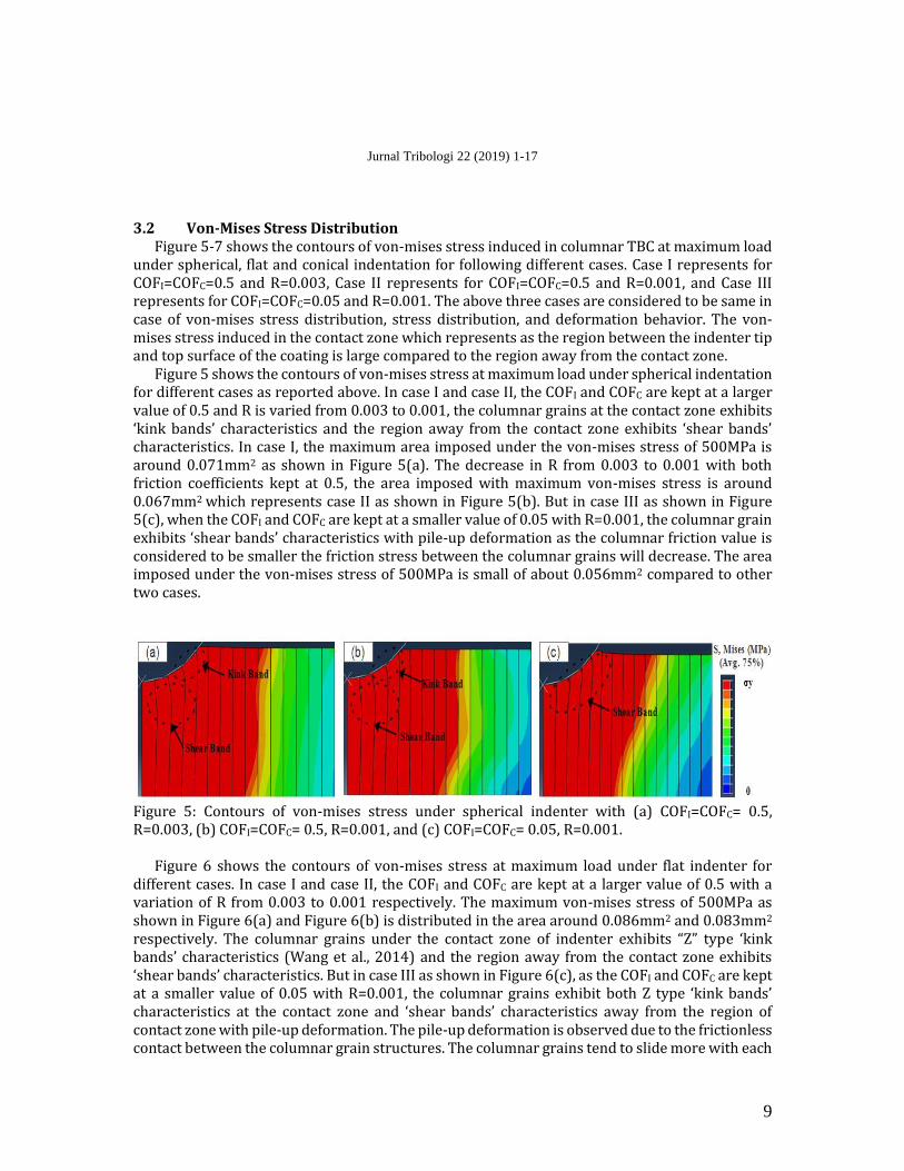
For case III, the value of R=0.001 and the columnar friction of 0.5 are kept constant and the
contact friction is varied from 0.05 to 0.5. From Figure 4, it is clear that with an increase in the value of contact friction from 0.05 to 0.5, there is an increase in the corresponding load imposed on to the surface of the columnar structure. The effect of contact friction on maximum load is significant for all three types of indenter i.e. spherical, flat and conical indenters respectively. The load value increases by 4.99% for spherical, 4.21% for flat and 4.09% for conical indenters with an increase in the contact friction from 0.05 to 0.5. For contact friction of 0.05, the value of load imposed with flat indenter is larger by 39.37% with respect to spherical and 40.45% with respect to conical indenter. Whereas the increase in the load with spherical indenter is large by 1.78% with respect to conical indenter. The effect of a change in contact friction from frictionless to sticking contact results in the small amount of increase in load due to the discontinuous nature of contact between the indenter and columnar grains. From the above cases, it is observed that the variation in the columnar friction results in the maximum change in load imposed due to the slip resistance in the columnar grain structure irrespective of the indenter shape. Therefore, the columnar friction plays a significant role in controlling the deformation behavior whereas the ratio of columnar gap to the width has the least effect with essentially no effect of contact friction on the deformation behavior of the columnar structure.
Figure 4: Load vs. displacement behavior with (a) spherical, (b) flat and (c) conical indenter for R=0.001 and COFC= 0.5 with a variation of COFI.
Jurnal Tribologi 22 (2019) 1-17
9
3.2 Von-Mises Stress Distribution Figure 5-7 shows the contours of von-mises stress induced in columnar TBC at maximum load
under spherical, flat and conical indentation for following different cases. Case I represents for COFI=COFC=0.5 and R=0.003, Case II represents for COFI=COFC=0.5 and R=0.001, and Case III represents for COFI=COFC=0.05 and R=0.001. The above three cases are considered to be same in case of von-mises stress distribution, stress distribution, and deformation behavior. The von-mises stress induced in the contact zone which represents as the region between the indenter tip and top surface of the coating is large compared to the region away from the contact zone.
Figure 5 shows the contours of von-mises stress at maximum load under spherical indentation for different cases as reported above. In case I and case II, the COFI and COFC are kept at a larger value of 0.5 and R is varied from 0.003 to 0.001, the columnar grains at the contact zone exhibits ‘kink bands’ characteristics and the region away from the contact zone exhibits ‘shear bands’ characteristics. In case I, the maximum area imposed under the von-mises stress of 500MPa is around 0.071mm2 as shown in Figure 5(a). The decrease in R from 0.003 to 0.001 with both friction coefficients kept at 0.5, the area imposed with maximum von-mises stress is around 0.067mm2 which represents case II as shown in Figure 5(b). But in case III as shown in Figure 5(c), when the COFI and COFC are kept at a smaller value of 0.05 with R=0.001, the columnar grain exhibits ‘shear bands’ characteristics with pile-up deformation as the columnar friction value is considered to be smaller the friction stress between the columnar grains will decrease. The area imposed under the von-mises stress of 500MPa is small of about 0.056mm2 compared to other two cases.
Figure 5: Contours of von-mises stress under spherical indenter with (a) COFI=COFC= 0.5, R=0.003, (b) COFI=COFC= 0.5, R=0.001, and (c) COFI=COFC= 0.05, R=0.001.
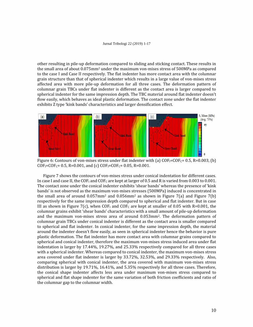
Figure 6 shows the contours of von-mises stress at maximum load under flat indenter for
different cases. In case I and case II, the COFI and COFC are kept at a larger value of 0.5 with a variation of R from 0.003 to 0.001 respectively. The maximum von-mises stress of 500MPa as shown in Figure 6(a) and Figure 6(b) is distributed in the area around 0.086mm2 and 0.083mm2 respectively. The columnar grains under the contact zone of indenter exhibits “Z” type ‘kink bands’ characteristics (Wang et al., 2014) and the region away from the contact zone exhibits ‘shear bands’ characteristics. But in case III as shown in Figure 6(c), as the COFI and COFC are kept at a smaller value of 0.05 with R=0.001, the columnar grains exhibit both Z type ‘kink bands’ characteristics at the contact zone and ‘shear bands’ characteristics away from the region of contact zone with pile-up deformation. The pile-up deformation is observed due to the frictionless contact between the columnar grain structures. The columnar grains tend to slide more with each
Jurnal Tribologi 22 (2019) 1-17
10
other resulting in pile-up deformation compared to sliding and sticking contact. These results in the small area of about 0.075mm2 under the maximum von-mises stress of 500MPa as compared to the case I and Case II respectively. The flat indenter has more contact area with the columnar grain structure than that of spherical indenter which results in a large value of von-mises stress affected area with more pile-up deformation for all three cases. The deformation pattern of columnar grain TBCs under flat indenter is different as the contact area is larger compared to spherical indenter for the same impression depth. The TBC material around flat indenter doesn’t flow easily, which behaves as ideal plastic deformation. The contact zone under the flat indenter exhibits Z type ‘kink bands’ characteristics and larger densification effect.
Figure 6: Contours of von-mises stress under flat indenter with (a) COFI=COFC= 0.5, R=0.003, (b) COFI=COFC= 0.5, R=0.001, and (c) COFI=COFC= 0.05, R=0.001.
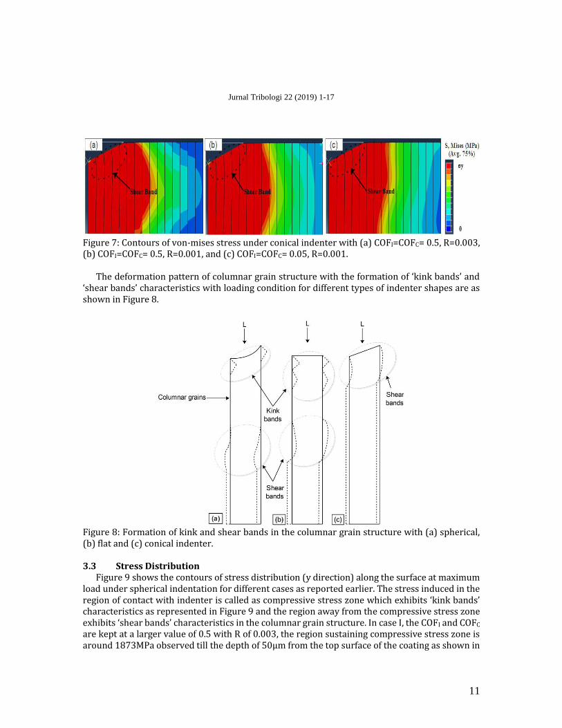
Figure 7 shows the contours of von-mises stress under conical indentation for different cases. In case I and case II, the COFI and COFC are kept at larger of 0.5 and R is varied from 0.003 to 0.001. The contact zone under the conical indenter exhibits ‘shear bands’ whereas the presence of ‘kink bands’ is not observed as the maximum von-mises stresses (500MPa) induced is concentrated in the small area of around 0.057mm2 and 0.056mm2 as shown in Figure 7(a) and Figure 7(b) respectively for the same impression depth compared to spherical and flat indenter. But in case III as shown in Figure 7(c), when COFI and COFC are kept at smaller of 0.05 with R=0.001, the columnar grains exhibit ‘shear bands’ characteristics with a small amount of pile-up deformation and the maximum von-mises stress area of around 0.053mm2. The deformation pattern of columnar grain TBCs under conical indenter is different as the contact area is smaller compared to spherical and flat indenter. In conical indenter, for the same impression depth, the material around the indenter doesn’t flow easily, as seen in spherical indenter hence the behavior is pure plastic deformation. The flat indenter has more contact area with columnar grains compared to spherical and conical indenter, therefore the maximum von-mises stress induced area under flat indentation is larger by 17.44%, 19.27%, and 25.33% respectively compared for all three cases with a spherical indenter. Whereas compared to conical indenter, the maximum von-mises stress area covered under flat indenter is larger by 33.72%, 32.53%, and 29.33% respectively. Also, comparing spherical with conical indenter, the area covered with maximum von-mises stress distribution is larger by 19.71%, 16.41%, and 5.35% respectively for all three cases. Therefore, the conical shape indenter affects less area under maximum von-mises stress compared to spherical and flat shape indenter for the same variation of both friction coefficients and ratio of the columnar gap to the columnar width.
Jurnal Tribologi 22 (2019) 1-17
11
Figure 7: Contours of von-mises stress under conical indenter with (a) COFI=COFC= 0.5, R=0.003, (b) COFI=COFC= 0.5, R=0.001, and (c) COFI=COFC= 0.05, R=0.001.
The deformation pattern of columnar grain structure with the formation of ‘kink bands’ and
‘shear bands’ characteristics with loading condition for different types of indenter shapes are as shown in Figure 8.
Figure 8: Formation of kink and shear bands in the columnar grain structure with (a) spherical, (b) flat and (c) conical indenter.
3.3 Stress Distribution
Figure 9 shows the contours of stress distribution (y direction) along the surface at maximum load under spherical indentation for different cases as reported earlier. The stress induced in the region of contact with indenter is called as compressive stress zone which exhibits ‘kink bands’ characteristics as represented in Figure 9 and the region away from the compressive stress zone exhibits ‘shear bands’ characteristics in the columnar grain structure. In case I, the COFI and COFC are kept at a larger value of 0.5 with R of 0.003, the region sustaining compressive stress zone is around 1873MPa observed till the depth of 50µm from the top surface of the coating as shown in
Jurnal Tribologi 22 (2019) 1-17
12
Figure 9(a). The region away from the compressive stress zone sustains the compressive stress of about 1435MPa. In case II, when COFI and COFC are kept at a larger value of 0.5 with a change in the R from 0.003 to 0.001, the area under compressive stress zone of about 1853MPa is increased and observed till the depth of 80µm as shown in Figure 9(b). The region away from the compressive stress zone sustains stress around 1430MPa. But in case III, when the COFI and COFC are kept at a smaller value of 0.05 with R=0.001, the region sustaining compressive stress zone of 1435MPa is induced and found till the depth of 150µm and away from the compressive stress zone is of about 1057MPa as shown in Figure 9(c). Comparing above cases, it is found that when both friction coefficients are considered to be smaller with the smaller R, the area under compressive stress zone is large compared to the larger value of both friction coefficients with the same R
Figure 9: Contours of stress distribution at maximum load under spherical indenter with (a) COFI=COFC= 0.5, R=0.003, (b) COFI=COFC= 0.5, R=0.001, and (c) COFI=COFC= 0.05, R=0.001.
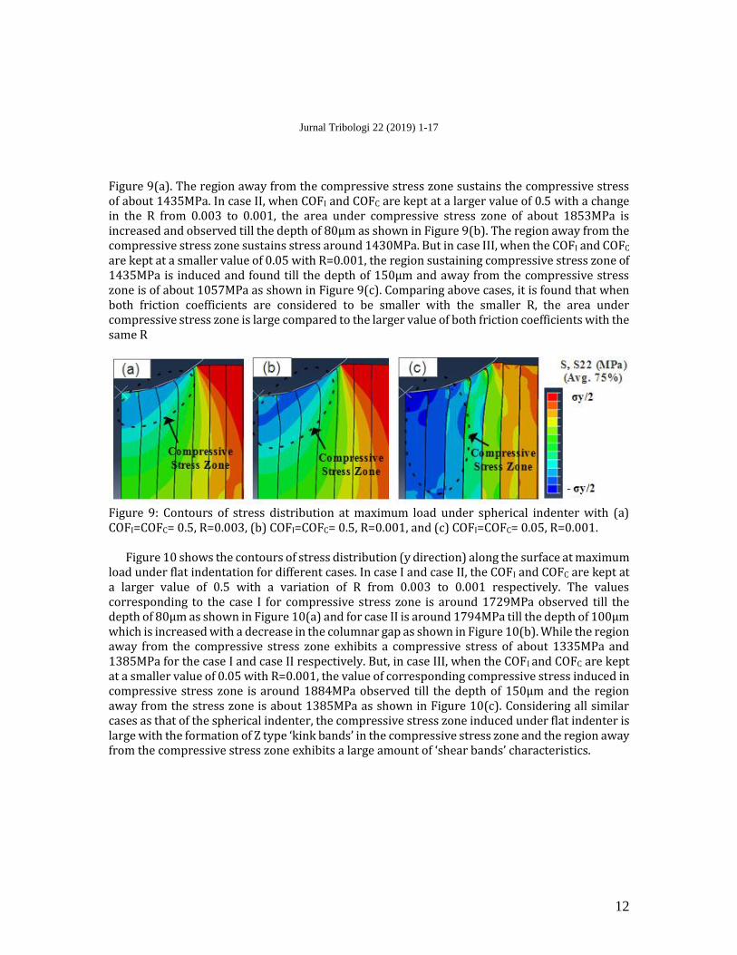
Figure 10 shows the contours of stress distribution (y direction) along the surface at maximum load under flat indentation for different cases. In case I and case II, the COFI and COFC are kept at a larger value of 0.5 with a variation of R from 0.003 to 0.001 respectively. The values corresponding to the case I for compressive stress zone is around 1729MPa observed till the depth of 80µm as shown in Figure 10(a) and for case II is around 1794MPa till the depth of 100µm which is increased with a decrease in the columnar gap as shown in Figure 10(b). While the region away from the compressive stress zone exhibits a compressive stress of about 1335MPa and 1385MPa for the case I and case II respectively. But, in case III, when the COFI and COFC are kept at a smaller value of 0.05 with R=0.001, the value of corresponding compressive stress induced in compressive stress zone is around 1884MPa observed till the depth of 150µm and the region away from the stress zone is about 1385MPa as shown in Figure 10(c). Considering all similar cases as that of the spherical indenter, the compressive stress zone induced under flat indenter is large with the formation of Z type ‘kink bands’ in the compressive stress zone and the region away from the compressive stress zone exhibits a large amount of ‘shear bands’ characteristics.
Jurnal Tribologi 22 (2019) 1-17
13
Figure 10: Contours of stress distribution at maximum load under flat indenter with (a) COFI=COFC= 0.5, R=0.003, (b) COFI=COFC= 0.5, R=0.001, and (c) COFI=COFC= 0.05, R=0.001.
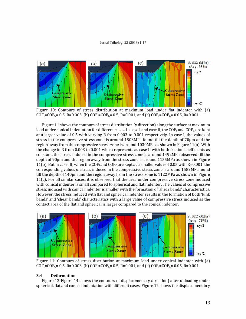
Figure 11 shows the contours of stress distribution (y direction) along the surface at maximum
load under conical indentation for different cases. In case I and case II, the COFI and COFC are kept at a larger value of 0.5 with varying R from 0.003 to 0.001 respectively. In case I, the values of stress in the compressive stress zone is around 1503MPa found till the depth of 70µm and the region away from the compressive stress zone is around 1030MPa as shown in Figure 11(a). With the change in R from 0.003 to 0.001 which represents as case II with both friction coefficients as constant, the stress induced in the compressive stress zone is around 1492MPa observed till the depth of 90µm and the region away from the stress zone is around 1155MPa as shown in Figure 11(b). But in case III, when the COFI and COFC are kept at a smaller value of 0.05 with R=0.001, the corresponding values of stress induced in the compressive stress zone is around 1582MPa found till the depth of 140µm and the region away from the stress zone is 1122MPa as shown in Figure 11(c). For all similar cases, it is observed that the area under compressive stress zone induced with conical indenter is small compared to spherical and flat indenter. The values of compressive stress induced with conical indenter is smaller with the formation of ‘shear bands’ characteristics. However, the stress induced with flat and spherical indenter results in the formation of both ‘kink bands’ and ‘shear bands’ characteristics with a large value of compressive stress induced as the contact area of the flat and spherical is larger compared to the conical indenter.
Figure 11: Contours of stress distribution at maximum load under conical indenter with (a) COFI=COFC= 0.5, R=0.003, (b) COFI=COFC= 0.5, R=0.001, and (c) COFI=COFC= 0.05, R=0.001.
3.4 Deformation
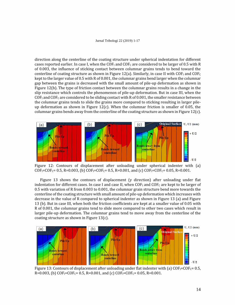
Figure 12-Figure 14 shows the contours of displacement (y direction) after unloading under spherical, flat and conical indentation with different cases. Figure 12 shows the displacement in y
Jurnal Tribologi 22 (2019) 1-17
14
direction along the centerline of the coating structure under spherical indentation for different cases reported earlier. In case I, when the COFI and COFC are considered to be larger of 0.5 with R of 0.003, the influence of sticking contact between columnar grains tends to bend toward the centerline of coating structure as shown in Figure 12(a). Similarly, in case II with COFI and COFC kept to the larger value of 0.5 with R of 0.001, the columnar grains bend larger when the columnar gap between the grains is decreased with the small amount of pile-up deformation as shown in Figure 12(b). The type of friction contact between the columnar grains results in a change in the slip resistance which controls the phenomenon of pile-up deformation. But in case III, when the COFI and COFC are considered to be sliding contact with R of 0.001, the smaller resistance between the columnar grains tends to slide the grains more compared to sticking resulting in larger pile-up deformation as shown in Figure 12(c). When the columnar friction is smaller of 0.05, the columnar grains bends away from the centerline of the coating structure as shown in Figure 12(c).
Figure 12: Contours of displacement after unloading under spherical indenter with (a) COFI=COFC= 0.5, R=0.003, (b) COFI=COFC= 0.5, R=0.001, and (c) COFI=COFC= 0.05, R=0.001.
Figure 13 shows the contours of displacement (y direction) after unloading under flat
indentation for different cases. In case I and case II, when COFI and COFC are kept to be larger of 0.5 with variation of R from 0.003 to 0.001, the columnar grain structure bend more towards the centerline of the coating structure with small amount of pile-up deformation which increases with decrease in the value of R compared to spherical indenter as shown in Figure 13 (a) and Figure 13 (b). But in case III, when both the friction coefficients are kept at a smaller value of 0.05 with R of 0.001, the columnar grains tend to slide more compared to other two cases which result in larger pile-up deformation. The columnar grains tend to move away from the centerline of the coating structure as shown in Figure 13(c).
Figure 13: Contours of displacement after unloading under flat indenter with (a) COFI=COFC= 0.5, R=0.003, (b) COFI=COFC= 0.5, R=0.001, and (c) COFI=COFC= 0.05, R=0.001.
Jurnal Tribologi 22 (2019) 1-17
15
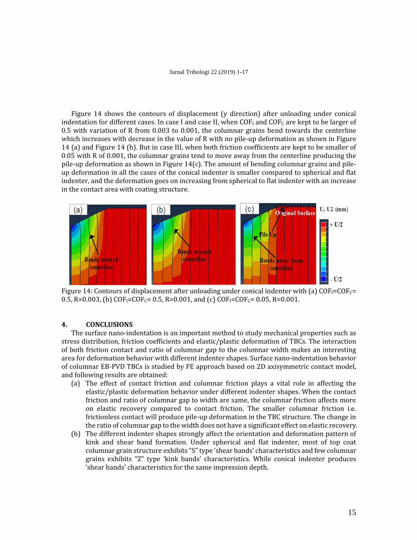
Figure 14 shows the contours of displacement (y direction) after unloading under conical
indentation for different cases. In case I and case II, when COFI and COFC are kept to be larger of 0.5 with variation of R from 0.003 to 0.001, the columnar grains bend towards the centerline which increases with decrease in the value of R with no pile-up deformation as shown in Figure 14 (a) and Figure 14 (b). But in case III, when both friction coefficients are kept to be smaller of 0.05 with R of 0.001, the columnar grains tend to move away from the centerline producing the pile-up deformation as shown in Figure 14(c). The amount of bending columnar grains and pile-up deformation in all the cases of the conical indenter is smaller compared to spherical and flat indenter, and the deformation goes on increasing from spherical to flat indenter with an increase in the contact area with coating structure.
Figure 14: Contours of displacement after unloading under conical indenter with (a) COFI=COFC= 0.5, R=0.003, (b) COFI=COFC= 0.5, R=0.001, and (c) COFI=COFC= 0.05, R=0.001.
4. CONCLUSIONS
The surface nano-indentation is an important method to study mechanical properties such as stress distribution, friction coefficients and elastic/plastic deformation of TBCs. The interaction of both friction contact and ratio of columnar gap to the columnar width makes an interesting area for deformation behavior with different indenter shapes. Surface nano-indentation behavior of columnar EB-PVD TBCs is studied by FE approach based on 2D axisymmetric contact model, and following results are obtained:
(a) The effect of contact friction and columnar friction plays a vital role in affecting the elastic/plastic deformation behavior under different indenter shapes. When the contact friction and ratio of columnar gap to width are same, the columnar friction affects more on elastic recovery compared to contact friction. The smaller columnar friction i.e. frictionless contact will produce pile-up deformation in the TBC structure. The change in the ratio of columnar gap to the width does not have a significant effect on elastic recovery.
(b) The different indenter shapes strongly affect the orientation and deformation pattern of kink and shear band formation. Under spherical and flat indenter, most of top coat columnar grain structure exhibits “S” type ‘shear bands’ characteristics and few columnar grains exhibits “Z” type ‘kink bands’ characteristics. While conical indenter produces ‘shear bands’ characteristics for the same impression depth.
Jurnal Tribologi 22 (2019) 1-17
16
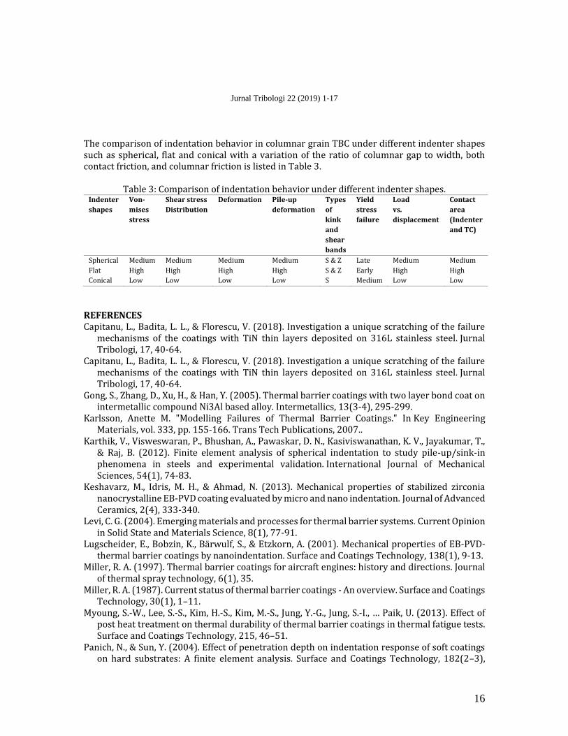
The comparison of indentation behavior in columnar grain TBC under different indenter shapes such as spherical, flat and conical with a variation of the ratio of columnar gap to width, both contact friction, and columnar friction is listed in Table 3.
Table 3: Comparison of indentation behavior under different indenter shapes. Indenter
shapes
Von-
mises
stress
Shear stress
Distribution
Deformation Pile-up
deformation
Types
of
kink
and
shear
bands
Yield
stress
failure
Load
vs.
displacement
Contact
area
(Indenter
and TC)
Spherical Medium Medium Medium Medium S & Z Late Medium Medium
Flat High High High High S & Z Early High High
Conical Low Low Low Low S Medium Low Low
REFERENCES Capitanu, L., Badita, L. L., & Florescu, V. (2018). Investigation a unique scratching of the failure
mechanisms of the coatings with TiN thin layers deposited on 316L stainless steel. Jurnal Tribologi, 17, 40-64.
Capitanu, L., Badita, L. L., & Florescu, V. (2018). Investigation a unique scratching of the failure mechanisms of the coatings with TiN thin layers deposited on 316L stainless steel. Jurnal Tribologi, 17, 40-64.
Gong, S., Zhang, D., Xu, H., & Han, Y. (2005). Thermal barrier coatings with two layer bond coat on intermetallic compound Ni3Al based alloy. Intermetallics, 13(3-4), 295-299.
Karlsson, Anette M. "Modelling Failures of Thermal Barrier Coatings." In Key Engineering Materials, vol. 333, pp. 155-166. Trans Tech Publications, 2007..
Karthik, V., Visweswaran, P., Bhushan, A., Pawaskar, D. N., Kasiviswanathan, K. V., Jayakumar, T., & Raj, B. (2012). Finite element analysis of spherical indentation to study pile-up/sink-in phenomena in steels and experimental validation. International Journal of Mechanical Sciences, 54(1), 74-83.
Keshavarz, M., Idris, M. H., & Ahmad, N. (2013). Mechanical properties of stabilized zirconia nanocrystalline EB-PVD coating evaluated by micro and nano indentation. Journal of Advanced Ceramics, 2(4), 333-340.
Levi, C. G. (2004). Emerging materials and processes for thermal barrier systems. Current Opinion in Solid State and Materials Science, 8(1), 77-91.
Lugscheider, E., Bobzin, K., Bärwulf, S., & Etzkorn, A. (2001). Mechanical properties of EB-PVD-thermal barrier coatings by nanoindentation. Surface and Coatings Technology, 138(1), 9-13.
Miller, R. A. (1997). Thermal barrier coatings for aircraft engines: history and directions. Journal of thermal spray technology, 6(1), 35.
Miller, R. A. (1987). Current status of thermal barrier coatings - An overview. Surface and Coatings Technology, 30(1), 1–11.
Myoung, S.-W., Lee, S.-S., Kim, H.-S., Kim, M.-S., Jung, Y.-G., Jung, S.-I., … Paik, U. (2013). Effect of post heat treatment on thermal durability of thermal barrier coatings in thermal fatigue tests. Surface and Coatings Technology, 215, 46–51.
Panich, N., & Sun, Y. (2004). Effect of penetration depth on indentation response of soft coatings on hard substrates: A finite element analysis. Surface and Coatings Technology, 182(2–3),
Jurnal Tribologi 22 (2019) 1-17
17
342–350. Schulz, U., Leyens, C., Fritscher, K., Peters, M., Saruhan-Brings, B., Lavigne, O., … Caliez, M. (2003).
Some recent trends in research and technology of advanced thermal barrier coatings. Aerospace Science and Technology, 7(1), 73–80.
Vasinonta, A., & Beuth, J. L. (2001). Measurement of interfacial toughness in thermal barrier coating systems by indentation. Engineering Fracture Mechanics, 68(7), 843–860.
Wang, L., Zhong, X. H., Yang, J. S., Tao, S. Y., Zhang, W., Wang, Y., & Sun, X. G. (2014). Finite element simulation of surface micro-indentation behavior of yttria stabilized zirconia thermal barrier coatings with microstructural characteristic of columnar grains and sub-grains based on a nonlinear contact model. Computational Materials Science, 82, 244–256.
Zhang, D., Zhao, Z., Wang, B., Li, S., & Zhang, J. (2016). Investigation of a new type of composite ceramics for thermal barrier coatings. Materials & Design, 112, 27–33.
Zhao, M., Chen, X., Yan, J., & Karlsson, A. M. (2006). Determination of uniaxial residual stress and mechanical properties by instrumented indentation. Acta Materialia, 54(10), 2823–2832.
Zisis, T., & Fleck, N. A. (2010). The elastic-plastic indentation response of a columnar thermal barrier coating. Wear, 268(2–3), 443–454.