Embed Size (px)
Citation preview
ICCM2014
28-30th
July, Cambridge, England
1
Finite Element Analysis of sustainable and deconstructable semi-rigid beam-to-
column composite joints
*Abdolreza Ataei1, Mark A. Bradford
2
1,2Centre for Infrastructure Engineering & Safety, School of Civil & Environmental Engineering, UNSW Australia,
Sydney, NSW 2052, Australia
Corresponding author: [email protected]
In this paper, an innovative sustainable semi-rigid beam-to-column composite joint with
deconstructable bolted shear connectors is modelled by using the general purpose software
ABAQUS. The structural mechanics of this joint considered in the paper requires careful
consideration, in order to capture the response accurately using computational techniques as the
interactions of the various components is complex. Three laboratory test specimens having
sustainable and deconstructable semi-rigid beam-to-column joints have been tested and the results
are used for validation of the finite element model. Precast “green concrete” (GC) slabs having
reduced CO2 emissions during their manufacture were attached compositely to the steel beam via
pre-tensioned bolted shear connectors, with the composite beam being connected to H-section
columns using a flush end plate with two rows of bolts. The experimental testing was full-sized,
with all the components being of the same size as would be met in practice. The numerical model
simulates the composite beam-to-column connection under hogging moment and includes the non-
linear material properties of all constitutive materials of the composite joint. For validation of the
computational procedure, the results of the numerical modelling are compared in the paper with the
experimental results, with good agreement being demonstrated.
Keywords: FE modelling, Semi-rigid composite joint, deconstructablility, Precast, Connections
Introduction
The traditional flush end plate semi-rigid composite connection is one of the best choices for connecting a composite beam to a column. This kind of connection has several advantages such as its ease of construction as well as being economical compared to a rigid connection. Apart from these benefits, the rigidity in this connection can allow for adequate moment distribution in the frames. These composite connections have higher initial stiffness and moment capacity as well as rotational capacity compared with steel connections, owing to the contribution of the reinforcing bars located in the slab. The induced tensile forces are resisted by the top bolts and the reinforcing bars and compressive forces are resisted by the steel beam. The reinforcing bars contribute significantly to the strength and stiffness of the connection. Traditional composite systems utilise concrete derived from Portland cement, which is one of the largest global sources of CO2 emissions. Moreover, the traditional composite floor systems such as a solid reinforced concrete slab or profiled metal decking floor systems are common systems in composite structures. For typical construction practices for these types of systems, concrete casting, profiled steel decking placing and conventional reinforcing detailing are undertaken on-site, which is time consuming and labour intensive, and which can increase the cost of construction, and they can lead to quality reductions in the construction industry. Combining precast GC slabs having reduced emissions during their manufacture with steel elements by using a deconstructable shear connection may solve these problems and concerns associated with traditional composite structures. Pre-tensioned high strength bolts installed through holes in precast GC slabs into pre-drilled holes in the steel beam produce a composite flooring system that can be deconstructed at the end of the life of the structure (Bradford and Pi 2012a,b, 2013; Rowe and Bradford 2013; Ataei and Bradford 2013; Lee and Bradford 2013). Marshall et al. (1971) appear to be the first researchers to have reported the use of bolted shear connection, but the context of the usage is not clear. Twelve push tests using high strength bolts as shear connectors were carried out and reported by Dallam (1968). In these set of tests, the bolts were embedded in the concrete slab and pre-tensioned by the turn-of-nut method after the concrete had aged 28 days. He pointed out
2
that high strength bolts displayed a higher capacity and ultimate strength than stud shear connectors. Six full-scale simply supported composite beams with high-strength bolted shear connectors were tested by Dallam and Harpster (1968), but the bolted shear connectors were embedded in the concrete slabs. Based on this, they concluded that pre-tensioned high strength bolts provide a very rigid connection between the steel beam and concrete slab at service loads, and a reserve capacity sufficient to develop the ultimate moment capacity of the fully composite section is attainable. A series of tests was conducted on three types of 22-mm diameter post-installed shear connectors under static and fatigue loading by Kwon et al. (2010). It was concluded that bolted shear connectors exhibited significantly higher fatigue strengths than stud shear connectors. Five full-scale non-composite beams were constructed to investigate the retrofitting of the bridge beams by Kwon et al. (2011). The reinforced concrete slabs were attached compositely to the steel girder via post-installed connectors in four beams. It was concluded that the strength and stiffness of the non-composite bridge girder can be improved significantly. In the tests conducted by Kwon et al. (2010, 2011), the bolts were embedded in the concrete or grout. Lee and Bradford (2013) conducted two series of push-out tests to obtain the behaviour of the post-installed pre-tensioned bolted shear connectors. The first and the second series of this experimental study included five and four push-out specimens, respectively. All specimens in the first series and two specimens in the second series were constructed by using post-installed pre-tensioned bolted shear connectors. The major differences between the first and second series were size of the precast slab, the reinforcement and the number of bolts. These studies did not focus on the testing and modelling of deconstructable and sustainable semi-rigid flush end plate composite joints. In order to provide a robust and efficient means for modelling sustainable semi-rigid beam-to-column composite connections with deconstructable bolted shear connectors, the present paper presents a three-dimensional modelling using ABAQUS software. Three specimens having sustainable and deconstructable semi-rigid beam-to-column joints have been tested and the results are used for validation of the finite element model. Precast GC slabs are attached compositely to the steel beam via pre-tensioned bolted shear connectors and the composite beam is connected to H-section columns using a flush end plate with two rows of bolts. The model simulates a composite beam-to-column connection under hogging moment and it includes the non-linear material properties of all constitutive materials of the composite joint. Almost all components were modelled as being of the same size as in the experimental tests, including the steel beam, steel column, flush end plate and bolts in the connection region. For validation of the model, the results of the numerical modelling are compared with the experimental test results and good agreement is achieved. The modelling is shown to provide an efficacious technique for conducting parametric studies, so as to develop design guidance in this novel application in composite construction.
Finite Element Model
Material modelling
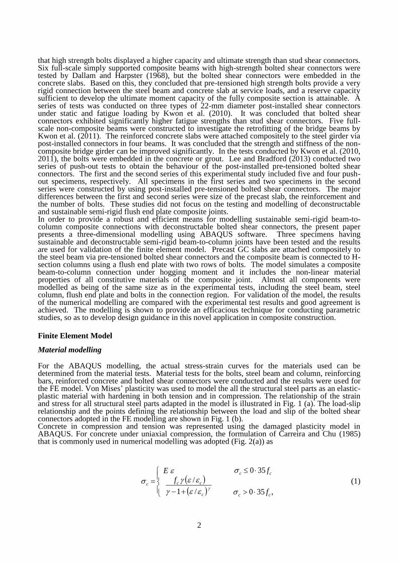
For the ABAQUS modelling, the actual stress-strain curves for the materials used can be determined from the material tests. Material tests for the bolts, steel beam and column, reinforcing bars, reinforced concrete and bolted shear connectors were conducted and the results were used for the FE model. Von Mises’ plasticity was used to model the all the structural steel parts as an elastic-plastic material with hardening in both tension and in compression. The relationship of the strain and stress for all structural steel parts adapted in the model is illustrated in Fig. 1 (a). The load-slip relationship and the points defining the relationship between the load and slip of the bolted shear connectors adopted in the FE modelling are shown in Fig. 1 (b). Concrete in compression and tension was represented using the damaged plasticity model in ABAQUS. For concrete under uniaxial compression, the formulation of Carreira and Chu (1985) that is commonly used in numerical modelling was adopted (Fig. 2(a)) as
c
cccf
E
/1
/
,350
350
cc
cc
f
f
(1)
3
where 0020 c ,
551432/3
cf (2)
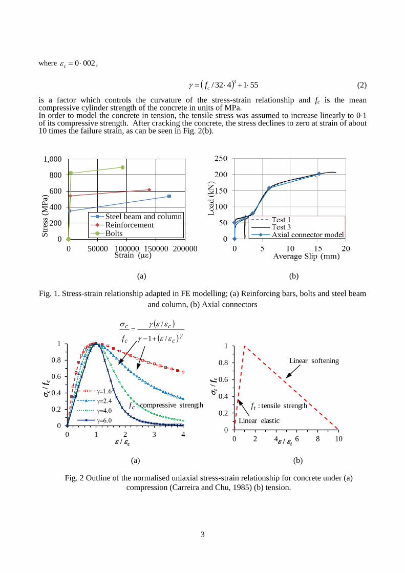
is a factor which controls the curvature of the stress-strain relationship and fc is the mean compressive cylinder strength of the concrete in units of MPa. In order to model the concrete in tension, the tensile stress was assumed to increase linearly to 01 of its compressive strength. After cracking the concrete, the stress declines to zero at strain of about 10 times the failure strain, as can be seen in Fig. 2(b).
(a) (b)
Fig. 1. Stress-strain relationship adapted in FE modelling; (a) Reinforcing bars, bolts and steel beam
and column, (b) Axial connectors
(a) (b)
Fig. 2 Outline of the normalised uniaxial stress-strain relationship for concrete under (a)
compression (Carreira and Chu, 1985) (b) tension.
0
200
400
600
800
1,000
0 50000 100000 150000 200000
Str
ess
(MP
a)
Strain ()
Steel beam and columnReinforcementBolts
0
0.2
0.4
0.6
0.8
1
0 1 2 3 4
c / f
c
/ c
1.6
2.4
4.0
6.0
0
0.2
0.4
0.6
0.8
1
0 2 4 6 8 10
t
/ f
t
/ t
c
c
c
c
f /1
/
strength tensile:tfstrength ecompressiv:cf
softeningLinear
elasticLinear
4
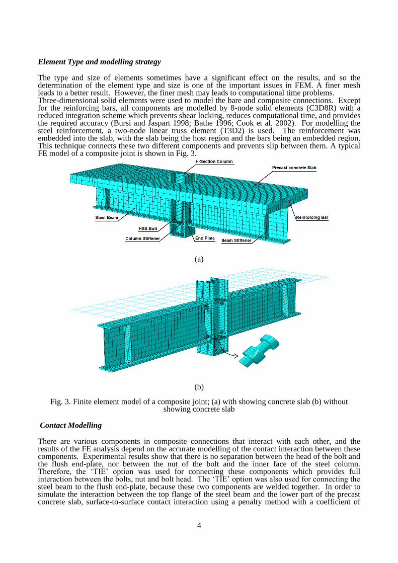
Element Type and modelling strategy
The type and size of elements sometimes have a significant effect on the results, and so the determination of the element type and size is one of the important issues in FEM. A finer mesh leads to a better result. However, the finer mesh may leads to computational time problems. Three-dimensional solid elements were used to model the bare and composite connections. Except for the reinforcing bars, all components are modelled by 8-node solid elements (C3D8R) with a reduced integration scheme which prevents shear locking, reduces computational time, and provides the required accuracy (Bursi and Jaspart 1998; Bathe 1996; Cook et al. 2002). For modelling the steel reinforcement, a two-node linear truss element (T3D2) is used. The reinforcement was embedded into the slab, with the slab being the host region and the bars being an embedded region. This technique connects these two different components and prevents slip between them. A typical FE model of a composite joint is shown in Fig. 3.
(a)
(b)
Fig. 3. Finite element model of a composite joint; (a) with showing concrete slab (b) without showing concrete slab
Contact Modelling
There are various components in composite connections that interact with each other, and the results of the FE analysis depend on the accurate modelling of the contact interaction between these components. Experimental results show that there is no separation between the head of the bolt and the flush end-plate, nor between the nut of the bolt and the inner face of the steel column. Therefore, the ‘TIE’ option was used for connecting these components which provides full interaction between the bolts, nut and bolt head. The ‘TIE’ option was also used for connecting the steel beam to the flush end-plate, because these two components are welded together. In order to simulate the interaction between the top flange of the steel beam and the lower part of the precast concrete slab, surface-to-surface contact interaction using a penalty method with a coefficient of
5
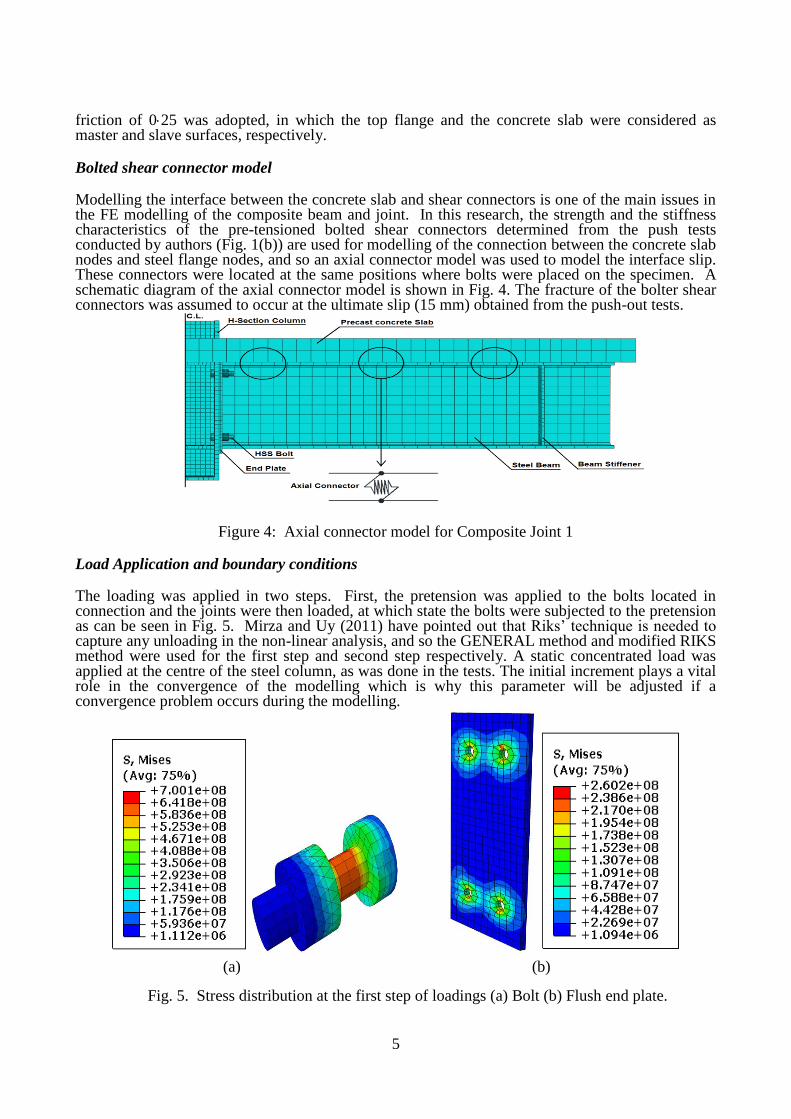
friction of 025 was adopted, in which the top flange and the concrete slab were considered as master and slave surfaces, respectively. Bolted shear connector model
Modelling the interface between the concrete slab and shear connectors is one of the main issues in the FE modelling of the composite beam and joint. In this research, the strength and the stiffness characteristics of the pre-tensioned bolted shear connectors determined from the push tests conducted by authors (Fig. 1(b)) are used for modelling of the connection between the concrete slab nodes and steel flange nodes, and so an axial connector model was used to model the interface slip. These connectors were located at the same positions where bolts were placed on the specimen. A schematic diagram of the axial connector model is shown in Fig. 4. The fracture of the bolter shear connectors was assumed to occur at the ultimate slip (15 mm) obtained from the push-out tests.
Figure 4: Axial connector model for Composite Joint 1
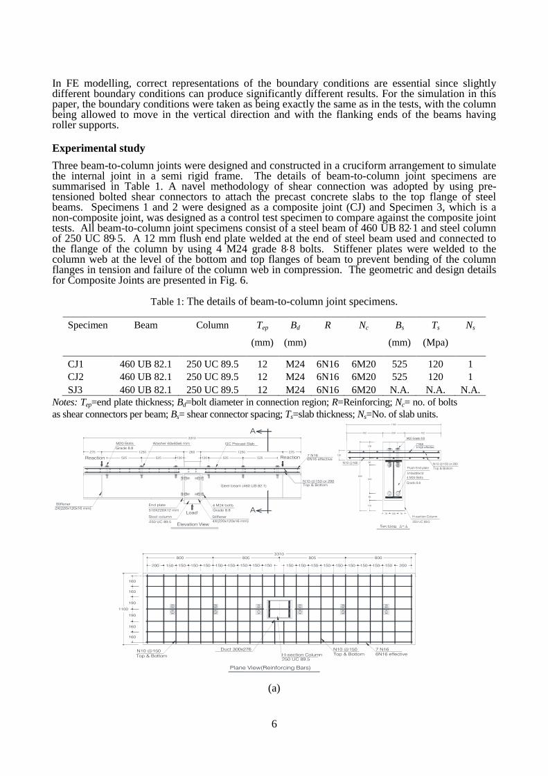
Load Application and boundary conditions
The loading was applied in two steps. First, the pretension was applied to the bolts located in connection and the joints were then loaded, at which state the bolts were subjected to the pretension as can be seen in Fig. 5. Mirza and Uy (2011) have pointed out that Riks’ technique is needed to capture any unloading in the non-linear analysis, and so the GENERAL method and modified RIKS method were used for the first step and second step respectively. A static concentrated load was applied at the centre of the steel column, as was done in the tests. The initial increment plays a vital role in the convergence of the modelling which is why this parameter will be adjusted if a convergence problem occurs during the modelling.
(a) (b)
Fig. 5. Stress distribution at the first step of loadings (a) Bolt (b) Flush end plate.
6
In FE modelling, correct representations of the boundary conditions are essential since slightly different boundary conditions can produce significantly different results. For the simulation in this paper, the boundary conditions were taken as being exactly the same as in the tests, with the column being allowed to move in the vertical direction and with the flanking ends of the beams having roller supports.
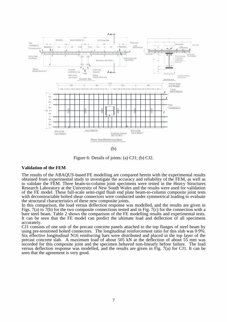
Experimental study
Three beam-to-column joints were designed and constructed in a cruciform arrangement to simulate the internal joint in a semi rigid frame. The details of beam-to-column joint specimens are summarised in Table 1. A navel methodology of shear connection was adopted by using pre-tensioned bolted shear connectors to attach the precast concrete slabs to the top flange of steel beams. Specimens 1 and 2 were designed as a composite joint (CJ) and Specimen 3, which is a non-composite joint, was designed as a control test specimen to compare against the composite joint tests. All beam-to-column joint specimens consist of a steel beam of 460 UB 821 and steel column of 250 UC 895. A 12 mm flush end plate welded at the end of steel beam used and connected to the flange of the column by using 4 M24 grade 88 bolts. Stiffener plates were welded to the column web at the level of the bottom and top flanges of beam to prevent bending of the column flanges in tension and failure of the column web in compression. The geometric and design details for Composite Joints are presented in Fig. 6.
Table 1: The details of beam-to-column joint specimens.
Specimen Beam Column Tep
(mm)
Bd
(mm)
R Nc Bs
(mm)
Ts
(Mpa)
Ns
CJ1 460 UB 82.1 250 UC 89.5 12 M24 6N16 6M20 525 120 1
CJ2 460 UB 82.1 250 UC 89.5 12 M24 6N16 6M20 525
120 1
SJ3 460 UB 82.1 250 UC 89.5 12 M24 6N16 6M20 N.A. N.A. N.A.
Notes: Tep=end plate thickness; Bd=bolt diameter in connection region; R=Reinforcing; Nc= no. of bolts
as shear connectors per beam; Bs= shear connector spacing; Ts=slab thickness; Ns=No. of slab units.
(a)
Reaction Reaction
Load
120 120525525
GC Precast Slab
525525
2601250 1250275 275
N10 @150 or 200
Top & Bottom
7 N16
6N16 effective
M20 Bolts
3310
Washer 60x60x6 mm
Elevation View
A
A
4X(220x120x16 mm)
Stiffener
2X(220x120x16 mm)
Stiffener
Steel beam (460 UB 82.1)
Steel column
250 UC 89.5
End plate
510X220X12 mm
4 M24 bolts
Grade 8.8
Grade 8.8
1100
830
125
85
340
85
195
422 422
4 M24 Bolts
120
256
78 78100
H-section Column
250 UC 89.5
Flush End plate
510x220x12
Grade 8.8
N10 @150 or 200
Top & Bottom
7 N16
6 N16 effective
N10 @160
M20 Grade 8.8
1100
805
3310
H-section Column
805800 800
150150200 150150150150150 200
160
7 N16
6N16 effective
Plane View(Reinforcing Bars)
150150 150
160
190
190
160
160
N10 @150
Top & Bottom
N10 @150
Top & Bottom
Duct 300x276
250 UC 89.5
150 150150 150 150150150150
7
(b)
Figure 6: Details of joints: (a) CJ1; (b) CJ2.
Validation of the FEM
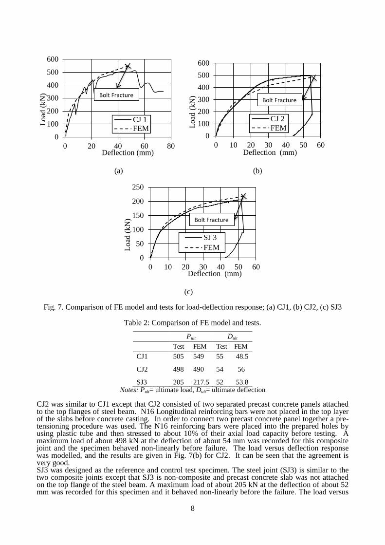
The results of the ABAQUS-based FE modelling are compared herein with the experimental results obtained from experimental study to investigate the accuracy and reliability of the FEM, as well as to validate the FEM. Three beam-to-column joint specimens were tested in the Heavy Structures Research Laboratory at the University of New South Wales and the results were used for validation of the FE model. These full-scale semi-rigid flush end plate beam-to-column composite joint tests with deconstructable bolted shear connectors were conducted under symmetrical loading to evaluate the structural characteristics of these new composite joints. In this comparison, the load versus deflection response was modelled, and the results are given in Figs. 7(a) to 7(b) for the two composite connections tested and in Fig. 7(c) for the connection with a bare steel beam. Table 2 shows the comparison of the FE modelling results and experimental tests. It can be seen that the FE model can predict the ultimate load and deflection of all specimens accurately. CJ1 consists of one unit of the precast concrete panels attached to the top flanges of steel beam by using pre-tensioned bolted connectors. The longitudinal reinforcement ratio for this slab was 09%. Six effective longitudinal N16 reinforcing bars were distributed and placed in the top layer of the precast concrete slab. A maximum load of about 505 kN at the deflection of about 55 mm was recorded for this composite joint and the specimen behaved non-linearly before failure. The load versus deflection response was modelled, and the results are given in Fig. 7(a) for CJ1. It can be seen that the agreement is very good.
Reaction Reaction
Load
120 120525525
GC Precast Slab
525525
2601250 1250275 275
N10 @150 or 200
Top & Bottom
7 N16
6N16 effective
M20 Bolts
4X(220x120x16 mm)
Stiffener
3310
Washer 60x60x6 mm
Elevation View
2X(220x120x16 mm)
Stiffener
A
A
Anchor Head
and Wedges
Plate
1100X80x8mm
Pre-tensioned bar
Steel beam (460 UB 82.1)
Steel column
250 UC 89.5
End plate
510X220X12 mm
4 M24 bolts
Grade 8.8
Plastic pipe
1100
830
125
85
340
85
195
422 422
4 M24 Bolts
120
Section A-A
256
78 78100
H-section Column
250 UC 89.5
Flush End plate
510x220x12
Grade 8.8
N10 @150
Top & Bottom
7 N16
6 N16 effective
N10 @160
M20 Grade 8.8Plastic pipe
1100
805
3310
H-section Column
805800 800
150150200 150150150150150 200
160
Plane View(Reinforcing Bars)
150150 150
160
190
190
160
160
N10 @150
Top & Bottom
N10 @150
Top & Bottom
Duct 300x276
250 UC 89.5
150 150150 150 150150150150
Anchor Head
and Wedges
7 N16
6N16 effective
Plate
1100X80x8mm
8
(a) (b)
(c)
Fig. 7. Comparison of FE model and tests for load-deflection response; (a) CJ1, (b) CJ2, (c) SJ3
Table 2: Comparison of FE model and tests.
Pult Dult
Test FEM Test FEM
CJ1 505 549 55 48.5
CJ2 498 490 54 56
SJ3 205 217.5 52 53.8 Notes: Pult= ultimate load, Dult= ultimate deflection
CJ2 was similar to CJ1 except that CJ2 consisted of two separated precast concrete panels attached to the top flanges of steel beam. N16 Longitudinal reinforcing bars were not placed in the top layer of the slabs before concrete casting. In order to connect two precast concrete panel together a pre-tensioning procedure was used. The N16 reinforcing bars were placed into the prepared holes by using plastic tube and then stressed to about 10% of their axial load capacity before testing. A maximum load of about 498 kN at the deflection of about 54 mm was recorded for this composite joint and the specimen behaved non-linearly before failure. The load versus deflection response was modelled, and the results are given in Fig. 7(b) for CJ2. It can be seen that the agreement is very good. SJ3 was designed as the reference and control test specimen. The steel joint (SJ3) is similar to the two composite joints except that SJ3 is non-composite and precast concrete slab was not attached on the top flange of the steel beam. A maximum load of about 205 kN at the deflection of about 52 mm was recorded for this specimen and it behaved non-linearly before the failure. The load versus
0
100
200
300
400
500
600
0 20 40 60 80
Load
(kN
)
Deflection (mm)
CJ 1
FEM0
100
200
300
400
500
600
0 10 20 30 40 50 60
Load
(kN
)
Deflection (mm)
CJ 2
FEM
0
50
100
150
200
250
0 10 20 30 40 50 60
Load
(kN
)
Deflection (mm)
SJ 3
FEM
Bolt Fracture Bolt Fracture
Bolt Fracture
9
deflection response was modelled, and the results are given in Fig. 7(c) for SJ3. It can be seen that the agreement is very good.
Failure modes
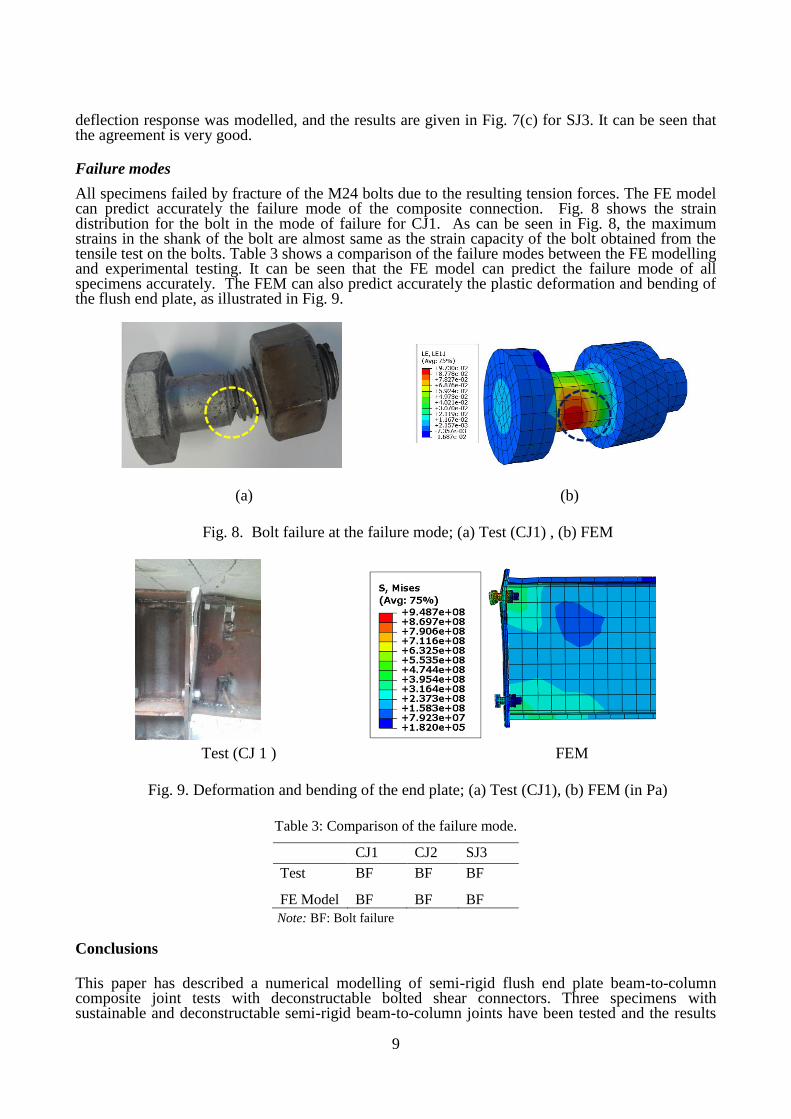
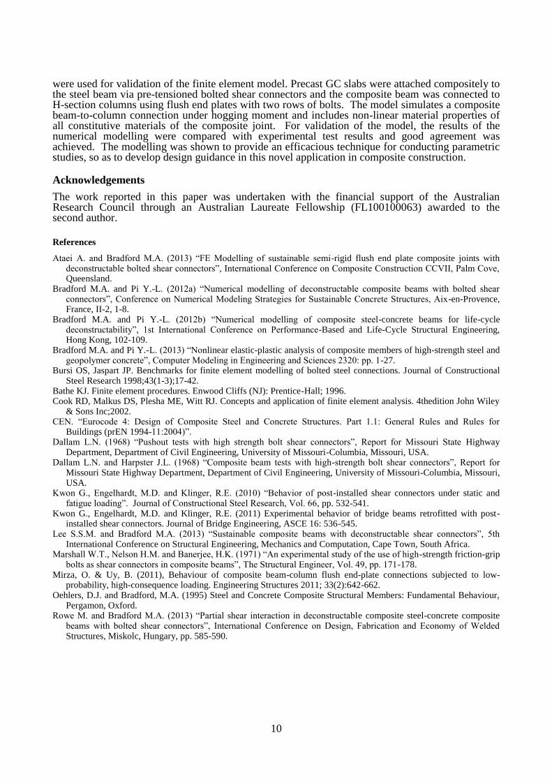
All specimens failed by fracture of the M24 bolts due to the resulting tension forces. The FE model can predict accurately the failure mode of the composite connection. Fig. 8 shows the strain distribution for the bolt in the mode of failure for CJ1. As can be seen in Fig. 8, the maximum strains in the shank of the bolt are almost same as the strain capacity of the bolt obtained from the tensile test on the bolts. Table 3 shows a comparison of the failure modes between the FE modelling and experimental testing. It can be seen that the FE model can predict the failure mode of all specimens accurately. The FEM can also predict accurately the plastic deformation and bending of the flush end plate, as illustrated in Fig. 9.
(a) (b)
Fig. 8. Bolt failure at the failure mode; (a) Test (CJ1) , (b) FEM
Test (CJ 1 ) FEM
Fig. 9. Deformation and bending of the end plate; (a) Test (CJ1), (b) FEM (in Pa)
Table 3: Comparison of the failure mode.
CJ1 CJ2 SJ3
Test BF BF BF
FE Model BF BF BF
Note: BF: Bolt failure
Conclusions
This paper has described a numerical modelling of semi-rigid flush end plate beam-to-column composite joint tests with deconstructable bolted shear connectors. Three specimens with sustainable and deconstructable semi-rigid beam-to-column joints have been tested and the results
10
were used for validation of the finite element model. Precast GC slabs were attached compositely to the steel beam via pre-tensioned bolted shear connectors and the composite beam was connected to H-section columns using flush end plates with two rows of bolts. The model simulates a composite beam-to-column connection under hogging moment and includes non-linear material properties of all constitutive materials of the composite joint. For validation of the model, the results of the numerical modelling were compared with experimental test results and good agreement was achieved. The modelling was shown to provide an efficacious technique for conducting parametric studies, so as to develop design guidance in this novel application in composite construction.
Acknowledgements
The work reported in this paper was undertaken with the financial support of the Australian Research Council through an Australian Laureate Fellowship (FL100100063) awarded to the second author.
References
Ataei A. and Bradford M.A. (2013) “FE Modelling of sustainable semi-rigid flush end plate composite joints with deconstructable bolted shear connectors”, International Conference on Composite Construction CCVII, Palm Cove, Queensland.
Bradford M.A. and Pi Y.-L. (2012a) “Numerical modelling of deconstructable composite beams with bolted shear connectors”, Conference on Numerical Modeling Strategies for Sustainable Concrete Structures, Aix-en-Provence, France, II-2, 1-8.
Bradford M.A. and Pi Y.-L. (2012b) “Numerical modelling of composite steel-concrete beams for life-cycle deconstructability”, 1st International Conference on Performance-Based and Life-Cycle Structural Engineering, Hong Kong, 102-109.
Bradford M.A. and Pi Y.-L. (2013) “Nonlinear elastic-plastic analysis of composite members of high-strength steel and geopolymer concrete”, Computer Modeling in Engineering and Sciences 2320: pp. 1-27.
Bursi OS, Jaspart JP. Benchmarks for finite element modelling of bolted steel connections. Journal of Constructional Steel Research 1998;43(1-3);17-42.
Bathe KJ. Finite element procedures. Enwood Cliffs (NJ): Prentice-Hall; 1996. Cook RD, Malkus DS, Plesha ME, Witt RJ. Concepts and application of finite element analysis. 4thedition John Wiley
& Sons Inc;2002. CEN. “Eurocode 4: Design of Composite Steel and Concrete Structures. Part 1.1: General Rules and Rules for
Buildings (prEN 1994-11:2004)”. Dallam L.N. (1968) “Pushout tests with high strength bolt shear connectors”, Report for Missouri State Highway
Department, Department of Civil Engineering, University of Missouri-Columbia, Missouri, USA. Dallam L.N. and Harpster J.L. (1968) “Composite beam tests with high-strength bolt shear connectors”, Report for
Missouri State Highway Department, Department of Civil Engineering, University of Missouri-Columbia, Missouri, USA.
Kwon G., Engelhardt, M.D. and Klinger, R.E. (2010) “Behavior of post-installed shear connectors under static and fatigue loading”. Journal of Constructional Steel Research, Vol. 66, pp. 532-541.
Kwon G., Engelhardt, M.D. and Klinger, R.E. (2011) Experimental behavior of bridge beams retrofitted with post-installed shear connectors. Journal of Bridge Engineering, ASCE 16: 536-545.
Lee S.S.M. and Bradford M.A. (2013) “Sustainable composite beams with deconstructable shear connectors”, 5th International Conference on Structural Engineering, Mechanics and Computation, Cape Town, South Africa.
Marshall W.T., Nelson H.M. and Banerjee, H.K. (1971) “An experimental study of the use of high-strength friction-grip bolts as shear connectors in composite beams”, The Structural Engineer, Vol. 49, pp. 171-178.
Mirza, O. & Uy, B. (2011), Behaviour of composite beam-column flush end-plate connections subjected to low-probability, high-consequence loading. Engineering Structures 2011; 33(2):642-662.
Oehlers, D.J. and Bradford, M.A. (1995) Steel and Concrete Composite Structural Members: Fundamental Behaviour, Pergamon, Oxford.
Rowe M. and Bradford M.A. (2013) “Partial shear interaction in deconstructable composite steel-concrete composite beams with bolted shear connectors”, International Conference on Design, Fabrication and Economy of Welded Structures, Miskolc, Hungary, pp. 585-590.