Embed Size (px)
Citation preview
FINITE ELEMENT ANALYSIS OF RECTANGULAR REINFORCED CONCRETE WALLS UNDER BI-DIRECTIONAL LOADING
A. NIROOMANDI1, S. PAMPANIN2, R. P. DHAKAL2, M. SOLEYMANI ASHTIANI3
1 PhD candidate, University of Canterbury 2 Professor, University of Canterbury
3 Structural Engineer, Ian Connor Consulting Ltd ABSTRACT Most of the experimental and numerical studies available in the literature on seismic assessment of rectangular Reinforced Concrete (RC) walls have focused on two-dimensional response using uni-directional cyclic loading testing protocol. While investigating RC members under bi-directional loading started several years ago, the effects of this type of loading regime on RC walls have not yet been fully understood and possibly underestimated. However, recent observations in Chile, New Zealand and Japan earthquakes have highlighted more complex failure mechanisms confirming the need for further investigations on the bi-directional response of walls. Perception of walls performing as 2D elements without being affected by bi-directional loading and complexity of test setup to investigate this behaviour, have potentially lead to such lack of data. Thus, it is necessary to develop a reliable numerical model capable of simulating RC walls under uni- and bi-directional loadings before any step towards experimental studies. In this paper DIANA, a nonlinear Finite Element (FE) based software, is utilised to simulate seismic response of rectangular RC walls subjected to uni- and bi-directional loadings. Curved shell and embedded bar elements are used in modelling. This type of model does not require plane sections to remain plane along the wall and steel reinforcing bars (longitudinal and transverse) along the length and width of the wall can be modelled in their actual locations. In addition, by using curved shell elements the out-of-plane deformations may be accounted for in case of bi-directional loading or to simulate out-of-plane instability. The numerical results are compared with a set of experimental data available in the literature. In order to validate the model, force-displacement curves and failure mechanisms of each wall under uni- and bi-directional loadings are compared to the experimental results. INTRODUCTION In recent earthquakes in Chile (2010) and New Zealand (2011), peculiar failure mechanisms were observed in RC walls (Fig. 1) which differed from the traditional 2D-based response [1]. Effect of bi-directional loading on the performance of RC walls was of interest which was typically ignored in code guidelines for both new design and assessment of existing buildings. In the past decades, the effects of bi-directional loading have been recognized and studied through experimental and numerical investigations for both columns [2-6] and beam-column joints [7, 8]. However, due to the inaccurate and simplistic assumption that walls would mostly respond as in-plane structural elements, the effect of bi-directional loading was overlooked for

walls. Even a structural ‘column’ with a section aspect ratio (length to width) higher than a certain threshold (i.e. four), is commonly considered to act as a wall, hence bi-directional loading effects are not considered.
(a) (b)
Fig. 1. Wall failure modes observed in recent earthquakes in (a) Chile [9] and (b) New Zealand [10]
A large number of experimental and numerical studies were conducted on seismic behaviour of RC walls; most of which focused on uni-directional cyclic lateral loading simulating the response of a proto-type structure during an earthquake. Only a small number of these studies scrutinized the bi-directional loading effects. Tatsuya [11] tested five one-third scaled wall specimens; one under uni-directional and four under bi-directional loadings. The tests showed a smaller deformational capacity for the specimens tested under bi-directional loading compared to the benchmark specimen subjected to uni-directional loading (by 33%). However, the same failure mode (web crushing) was observed in both cases. Nevertheless, not much difference was observed in shear strength and flexural stiffness between the two loading regimes. It should be noted that the walls tested by Tatsuya had a shear span ratio of 2 and axial load ratio between 13.3-17.4%. In a more recent experimental study by Kabeyasawa et al. [12], eight one-third scaled specimens were tested (four under uni-directional and four under bi-directional loading). The flexural strengths were not much different between the two loading types. However, under bi-directional loading, relatively smaller deformation capacity was observed compared to those tested under uni-directional loading (by 25-38%). It should be noted that the walls tested by Kabeyasawa et al. had shear span ratios of 1.925 and 2.31. Axial load ratios were between 7.5-12.4%. In this paper a FE model capable of simulating RC walls under bi-directional loading is utilized and validated with experimental results conducted by other researchers. Such model can be beneficial for the preliminary step of any experimental campaign on RC walls under bi-directional loading.
PROPOSED FINITE ELEMENT MODEL In this study, DIANA software [13] is used to simulate RC walls under cyclic loading. Dealing with the complexities involved in nonlinear concrete modelling (compressive and tensile behaviour) in RC structures, availability of material models to incorporate cyclic loading and powerful variety of elements are some of many appealing features of DIANA which led to the selection of this software [14-16]. A description of the adopted material and elements is provided below. Material models Concrete: total strain rotating crack model Total strain rotating crack model which is developed based on the Modified Compression Field Theory (MCFT), originally developed by Vecchio et al. [17] is used to model concrete. This model follows a smeared crack approach for the fracture energy [18]. Here the model proposed by Mander et al. [19] is used for both confined and unconfined concrete. The modulus of elasticity of concrete, Ec, is estimated using Eq. 1 [20].
cc fE '5000 (1)
Where, f’c is the compressive strength of concrete. The ultimate compression strain in concrete, εcu, is calculated using Eq. (2) which is proposed by Priestley et al. [21] and is a conservative estimation of the equation proposed by Mander et al. [19].
'4.1004.0 ccsuyhscu ff (2)
Where ρs = volumetric ratio of confining steel (ρs=ρx+ρy), ρx=Avx/(dc×s), ρy=Avy/(bc×s), ρx and ρy = transverse reinforcement ratios in the x and y directions, respectively, Avx and Avy = the total area of transverse bars running in the x and y directions, respectively, bc and dc = core dimensions to centrelines of perimeter hoop in the x and y directions, respectively, s = centre-to-centre spacing of hoops, fyh = yield stress of transverse reinforcement, εsu = steel strain at
maximum tensile stress and ccf ' = maximum confined concrete stress [19].
According to Priestley et al. [21], when the member is subjected to bending or combined bending and axial compression, ultimate compression strain resulting from Eq. (2) tends to be conservative by at least 50%. Therefore, the ultimate compression strain of concrete is considered 1.5 times that resulting from Eq. (1). One of the other inputs required for the total strain rotating crack model is the concrete response under uniaxial tensile loading. The uniaxial concrete response under tension is defined following the model proposed by Hordijk [22]. The fracture energy ‘Gf’ may be determined from Eq. (3) proposed by CEB-FIP model code 1990 [23].
7.010/'03.0 cf fG (3)
Steel reinforcement: Menegotto-Pinto model Cyclic performance of reinforced concrete elements is highly dependent on nonlinear response of reinforcing bars under cyclic loading. Reinforcing bars undergo cyclic degradation during loading reversal, which is an important nonlinear behaviour; more commonly known as the Bauschinger effect. The Menegotto-Pinto [24] model which has a bilinear backbone curve and considers Bauschinger effect is used to model steel reinforcements.
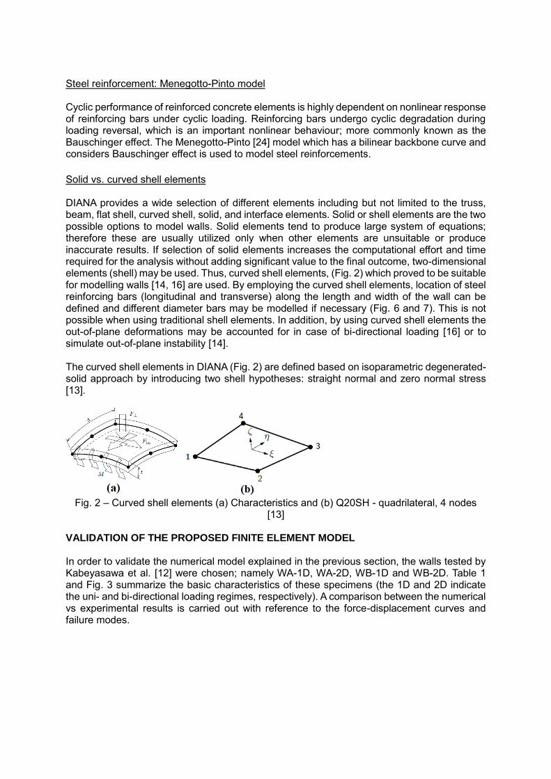
Solid vs. curved shell elements DIANA provides a wide selection of different elements including but not limited to the truss, beam, flat shell, curved shell, solid, and interface elements. Solid or shell elements are the two possible options to model walls. Solid elements tend to produce large system of equations; therefore these are usually utilized only when other elements are unsuitable or produce inaccurate results. If selection of solid elements increases the computational effort and time required for the analysis without adding significant value to the final outcome, two-dimensional elements (shell) may be used. Thus, curved shell elements, (Fig. 2) which proved to be suitable for modelling walls [14, 16] are used. By employing the curved shell elements, location of steel reinforcing bars (longitudinal and transverse) along the length and width of the wall can be defined and different diameter bars may be modelled if necessary (Fig. 6 and 7). This is not possible when using traditional shell elements. In addition, by using curved shell elements the out-of-plane deformations may be accounted for in case of bi-directional loading [16] or to simulate out-of-plane instability [14]. The curved shell elements in DIANA (Fig. 2) are defined based on isoparametric degenerated-solid approach by introducing two shell hypotheses: straight normal and zero normal stress [13].
Fig. 2 – Curved shell elements (a) Characteristics and (b) Q20SH - quadrilateral, 4 nodes
[13] VALIDATION OF THE PROPOSED FINITE ELEMENT MODEL In order to validate the numerical model explained in the previous section, the walls tested by Kabeyasawa et al. [12] were chosen; namely WA-1D, WA-2D, WB-1D and WB-2D. Table 1 and Fig. 3 summarize the basic characteristics of these specimens (the 1D and 2D indicate the uni- and bi-directional loading regimes, respectively). A comparison between the numerical vs experimental results is carried out with reference to the force-displacement curves and failure modes.
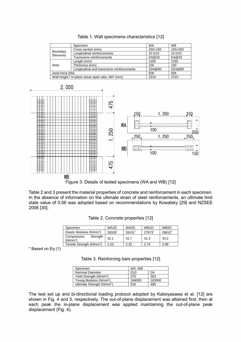
Table 1. Wall specimens characteristics [12]
Specimen WA WB
Boundary Elements
Cross section (mm) 250×150 150×250
Longitudinal reinforcements 10 D10 10 D10
Transverse reinforcements D4@33 D4@33
Web
Length (mm) 1350 1250
Thickness (mm) 100 100
Longitudinal and transverse reinforcements 2D4@80 2D4@80
Axial force (kN) 506 506
Wall height / In-plane shear span ratio, M/V (mm) 2310 2310
Figure 3. Details of tested specimens (WA and WB) [12]
Table 2 and 3 present the material properties of concrete and reinforcement in each specimen. In the absence of information on the ultimate strain of steel reinforcements, an ultimate limit state value of 0.06 was adopted based on recommendations by Kowalsky [29] and NZSEE 2006 [30].
Table 2. Concrete properties [12]
Specimen WA1D WA2D WB1D WB2D
Elastic Modulus (N/mm2) 28328* 28151* 27973* 28810*
Compressive Strength (N/mm2)
32.1 31.7 31.3 33.2
Tensile Strength (N/mm2) 2.33 2.32 2.74 2.98
* Based on Eq (1)
Table 3. Reinforcing bars properties [12]
Specimen WA, WB
Nominal Diameter D10 D4
Yield Strength (N/mm2) 375 353
Young Modulus (N/mm2) 184000 163000
Ultimate Strength (N/mm2) 516 485
The test set up and bi-directional loading protocol adopted by Kabeyasawa et al. [12] are shown in Fig. 4 and 5, respectively. The out-of-plane displacement was attained first, then at each peak the in-plane displacement was applied maintaining the out-of-plane peak displacement (Fig. 4).
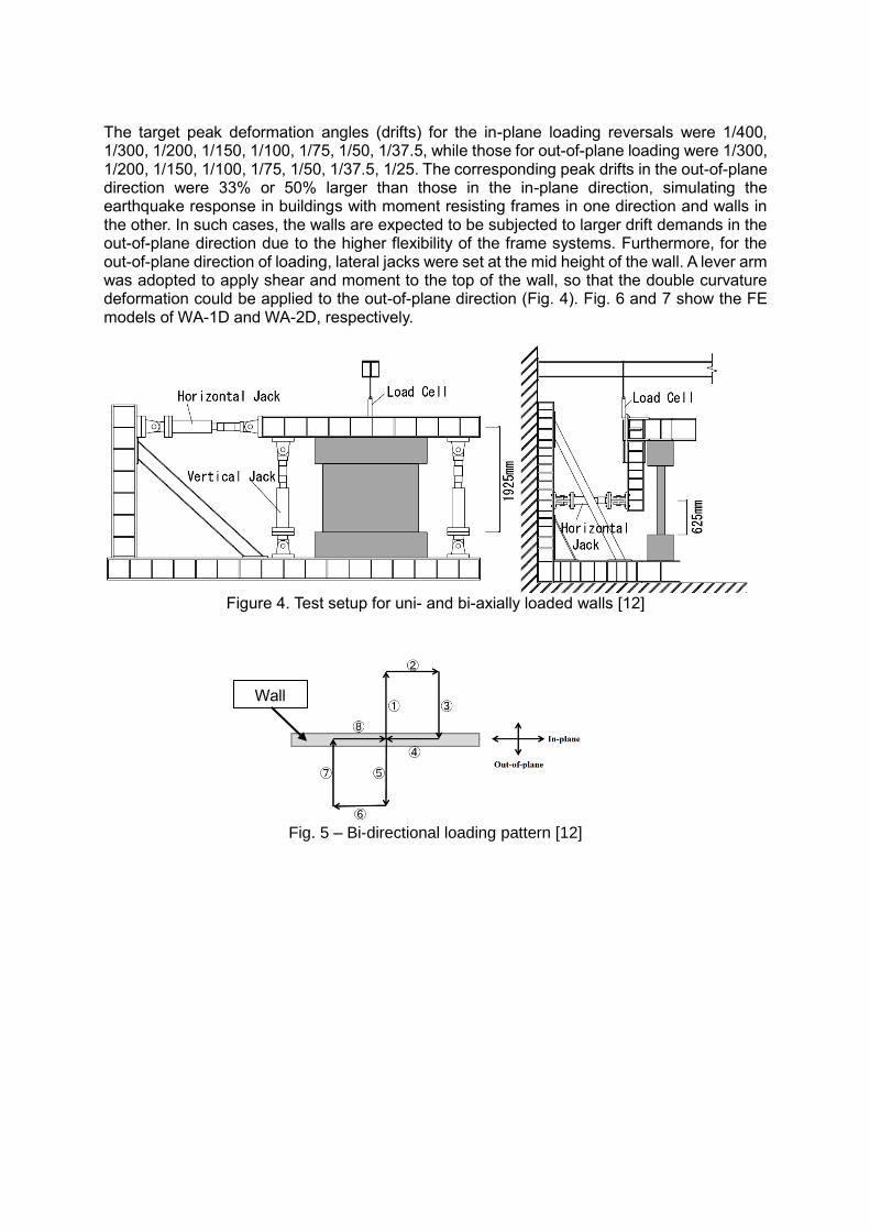
The target peak deformation angles (drifts) for the in-plane loading reversals were 1/400, 1/300, 1/200, 1/150, 1/100, 1/75, 1/50, 1/37.5, while those for out-of-plane loading were 1/300, 1/200, 1/150, 1/100, 1/75, 1/50, 1/37.5, 1/25. The corresponding peak drifts in the out-of-plane direction were 33% or 50% larger than those in the in-plane direction, simulating the earthquake response in buildings with moment resisting frames in one direction and walls in the other. In such cases, the walls are expected to be subjected to larger drift demands in the out-of-plane direction due to the higher flexibility of the frame systems. Furthermore, for the out-of-plane direction of loading, lateral jacks were set at the mid height of the wall. A lever arm was adopted to apply shear and moment to the top of the wall, so that the double curvature deformation could be applied to the out-of-plane direction (Fig. 4). Fig. 6 and 7 show the FE models of WA-1D and WA-2D, respectively.
Figure 4. Test setup for uni- and bi-axially loaded walls [12]
Fig. 5 – Bi-directional loading pattern [12]
Wall
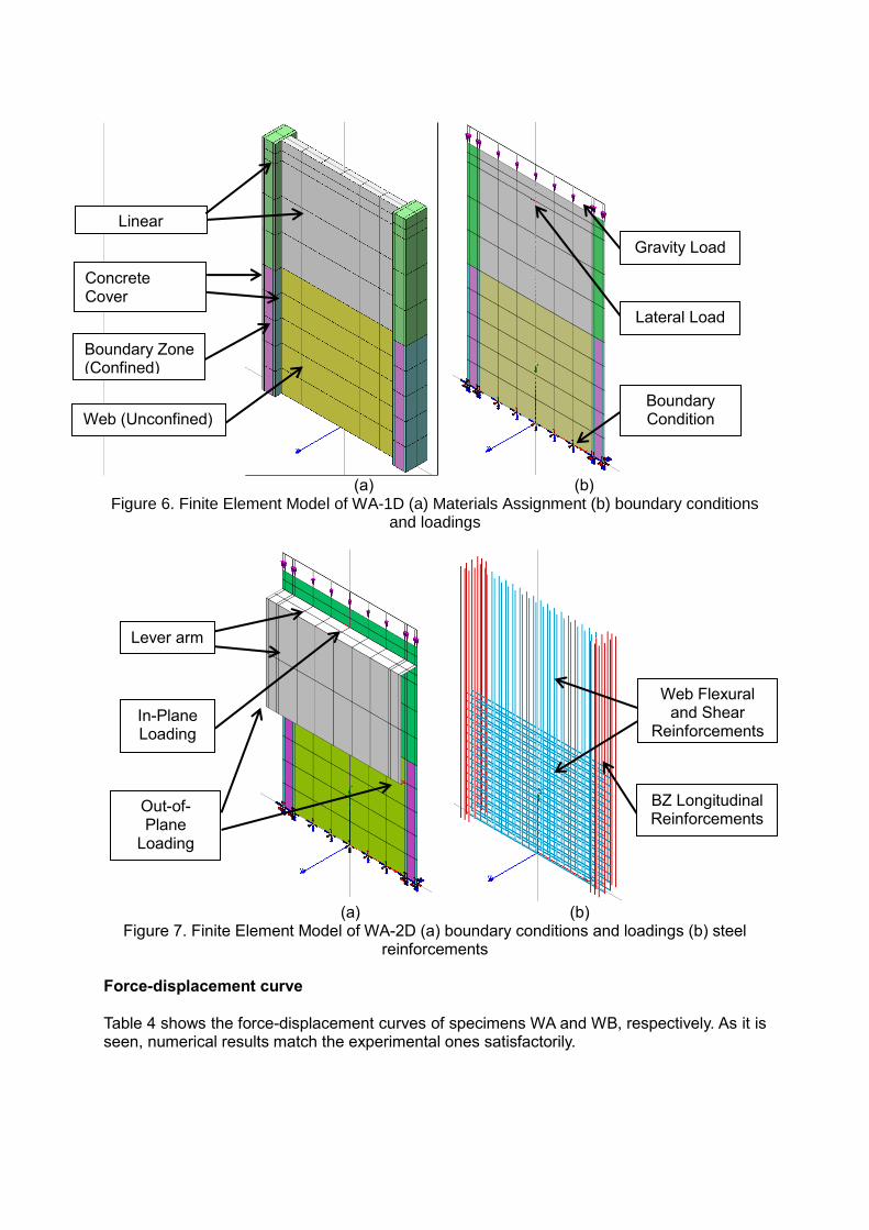
(a) (b) Figure 6. Finite Element Model of WA-1D (a) Materials Assignment (b) boundary conditions
and loadings
(a) (b)
Figure 7. Finite Element Model of WA-2D (a) boundary conditions and loadings (b) steel reinforcements
Force-displacement curve Table 4 shows the force-displacement curves of specimens WA and WB, respectively. As it is seen, numerical results match the experimental ones satisfactorily.
Linear Concrete
Concrete Cover (Unconfined)
Boundary Zone (Confined)
Web (Unconfined)
BZ Longitudinal Reinforcements
Web Flexural and Shear
Reinforcements
Gravity Load
Lever arm
Out-of-Plane
Loading
Lateral Load
Boundary Condition
In-Plane Loading

Table 4. Force-displacement curves, FE analyses vs experiment
Wall name
Uni-directional loading Bi-directional loading
WA
WB
Table 5 shows the ultimate drift, maximum strength capacity and failure mode of each wall. Note that the point of ultimate displacement is considered when 20% reduction in strength is reached [31]. As can be seen in this table, not much difference is observed in the flexural strengths and stiffness when the walls were under bi-directional loading. However under bi-directional loading, displacement capacity was decreased by 32 and 21% for WA and WB, respectively. The energy dissipation was also decreased in cases where walls underwent bi-directional loading.
Table 5 – Ultimate drift, maximum strength and failure mode of each wall
Wall name
Ultimate drift capacity Maximum strength capacity (kN)
Failure mode FE (+)
EXP (+)
FE (-) EXP (-) FE (+)
EXP (+)
FE (-) EXP (-)
WA-1D 0.032 0.037 -0.027 -0.027 470 454 -469 -478 Shear-flexure
WA-2D 0.025 0.028 -0.02 -0.021 452 440 -445 -440 Sliding shear
WB-1D 0.035 0.035 -0.027 -0.027 474 455 -475 -472 Shear-flexure
WB-2D 0.028 0.029 -0.023 -0.028 460 466 -456 -476 Sliding shear
Failure patterns Flexural behaviour was observed in the experiments for both specimens WA-1D and WB-1D under uni-directional loading, up to the cyclic loading with 2.67% drift. However, at the next loading cycle towards 4% drift, a brittle shear failure occurred in both specimens (WA-1D and WB-1D). It can be seen in Table 6.
-800
-600
-400
-200
0
200
400
600
800
-0.04 -0.03 -0.02 -0.01 0 0.01 0.02 0.03 0.04
Ho
riz
on
tal
Fo
rce
(kN
)
In-plane Drift Angle (rad.)
WA-1D DIANA
WA-1D EXP
-800
-600
-400
-200
0
200
400
600
800
-0.04 -0.03 -0.02 -0.01 0 0.01 0.02 0.03 0.04
Ho
rizo
nta
l F
orc
e (k
N)
In-plane Drift Angle (rad.)
WA-2D DIANA
WA-2D EXP
-800
-600
-400
-200
0
200
400
600
800
-0.04 -0.03 -0.02 -0.01 0 0.01 0.02 0.03 0.04
Ho
rizon
tal
Forc
e (
kN
)
In-plane Drift Angle (rad.)
WB-1D DIANA
WB-1D EXP
-800
-600
-400
-200
0
200
400
600
800
-0.04 -0.03 -0.02 -0.01 0 0.01 0.02 0.03 0.04
Horiz
on
tal
Forc
e (k
N)
In-plane Drift Angle (rad.)
WB-2D DIANA
WB-1D EXP
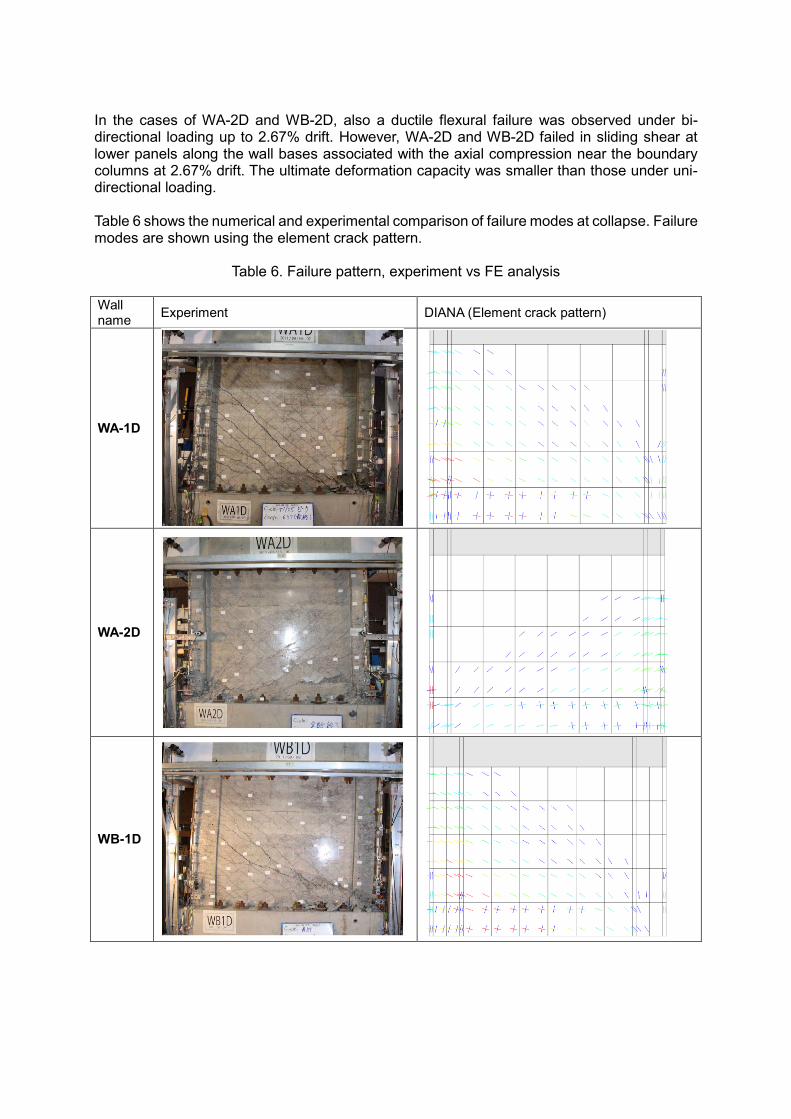
In the cases of WA-2D and WB-2D, also a ductile flexural failure was observed under bi-directional loading up to 2.67% drift. However, WA-2D and WB-2D failed in sliding shear at lower panels along the wall bases associated with the axial compression near the boundary columns at 2.67% drift. The ultimate deformation capacity was smaller than those under uni-directional loading. Table 6 shows the numerical and experimental comparison of failure modes at collapse. Failure modes are shown using the element crack pattern.
Table 6. Failure pattern, experiment vs FE analysis
Wall name
Experiment DIANA (Element crack pattern)
WA-1D
WA-2D
WB-1D

WB-2D
CONCLUSION After recent earthquakes in Chile (2010) and New Zealand (2011), some concerns arose regarding the seismic performance of RC walls and specifically regarding the effects of bi-directional loading on them. In this paper, a finite element model capable of simulating cyclic response of RC walls under uni- and bi-directional loading is utilized and validated with the experimental results available in the literature. It was shown that the FE model can simulate the behaviour of RC walls under uni- and bi-directional loadings and is able to predict the force-displacement curves and the failure mode of the wall. Such FE model can be used for numerical study purposes on RC walls under uni- and bi-directional loadings before any step towards experimental studies. Based on such experimental and numerical evidences, recommendations can be provided to improve current practice for both the design of new walls and the assessment of existing ones to assist engineers in their daily practice. ACKNOWLEDGEMENTS Financial support of this research was provided by the SAFER Concrete Research Project funded by the Natural Hazards Research Platform (NHRP) and the MBIE Wall project. REFERENCES 1. Paulay, T. and M.J.N. Priestley, seismic design of reinforced concrete and masonry
buildings. 1992, New York, USA: John Wiley & Sons, Inc. 2. Umehara, H. and J.O. Jirsa, Short rectangular RC columns under bidirectional
loadings. Journal of Structural Engineering, 1984. 110(3): p. 605-618. 3. Low, S.S. and J.P. Moehle, Experimental study of reinforced concrete columns
subjected to multi-axial cyclic loading. 1987: Earthquake Engineering Research Center, University of California.
4. Zeris, C.A. and S.A. Mahin, Behavior of reinforced concrete structures subjected to
biaxial excitation. Journal of structural engineering, 1991. 117(9): p. 2657-2673. 5. Qiu, F., et al., Experimental tests on reinforced concrete columns under biaxial quasi-
static loading. Engineering Structures, 2002. 24(4): p. 419-428.

6. Boys, A., D. Bull, and S. Pampanin. Seismic performance assessment of inadequately detailed reinforced concrete columns. in The New Zealand Society for Earthquake Engineering (NZSEE) Annual Technical Conference. 2008.
7. Leon, R. and J.O. Jirsa, Bidirectional loading of RC beam-column joints. Earthquake
spectra, 1986. 2(3): p. 537-564. 8. Akguzel, U. and S. Pampanin, Effects of variation of axial load and bidirectional loading
on seismic performance of GFRP retrofitted reinforced concrete exterior beam-column joints. Journal of Composites for Construction, 2010. 14(1): p. 94-104.
9. NIST, Recommendations for Seismic Design of Reinforced Concrete Wall Buildings
Based on Studies of the 2010 Maule, Chile Earthquake. 2014. 10. Elwood, K., S. Pampanin, and W.Y. Kam. 22 February 2011 Christchurch earthquake
and implications for the design of concrete structures. in The International Symposium on Engineering Lessons Learned from the 2011 Great East Japan Earthquake. 2012. Tokyo, Japan.
11. Tatsuya, I. Post-yield behaviours of multi-story reinforced concrete shear walls
subjected to bilateral deformations under axial loading. in The Eleventh World Conference on Earthquake Engineering. 1996.
12. Kabeyasawa, T., et al. Effects of bi-directional lateral loading on the strength and
deformability of reinforced concrete walls with/without boundary columns. in The Tenth U.S. National Conference on Earthquake Engineering. 2014.
13. DIANA, DIANA Manual Release 9.6, TNO DIANA BV. 2015: Delft, the Netherlands. 14. Dashti, F., R.P. Dhakal, and S. Pampanin. Numerical simulation of shear wall failure
mechanisms. in The New Zealand Society for Earthquake Engineering (NZSEE) Annual Technical Conference. 2014. Auckland, New Zealand.
15. Jünemann, R., et al. Inelastic finite element models to assess earthquake damage of
RC wall buildings. in The New Zealand Society for Earthquake Engineering (NZSEE) Annual Technical Conference. 2016. Christchurch, New Zealand.
16. Niroomandi, A., et al. Finite element analysis of RC rectangular shear walls under bi-
directional loading. in The New Zealand Society for Earthquake Engineering (NZSEE) Annual Technical Conference. 2016. Christchurch, New Zealand.
17. Vecchio, F.J. and M.P. Collins, The modified compression-field theory for reinforced
concrete elements subjected to shear. ACI J., 1986. 83(2): p. 219-231. 18. Litton, R.W., A contribution to the analysis of concrete structures under cyclic loading.
1975: University of California, Berkeley. 19. Mander, J.B., M.J.N. Priestley, and R. Park, Theoretical stress-strain model for
confined concrete. Journal of structural engineering, 1988. 114(8): p. 1804-1826. 20. Priestley, M.J.N., M.C. Calvi, and M.J. Kowalsky, Displacement-Based Seismic Design
of Structures. 2007, IUSS Press: Pavia, Italy. 21. Priestley, M.N., F. Seible, and G.M. Calvi, Seismic design and retrofit of bridges. 1996,
John Wiley & Sons: New York, USA.

22. Hordijk, D.A., Local approach to fatigue of concrete. 1991, TU Delft, Delft University of Technology.
23. CEB-FIP-Model-Code, Comite euro-international du beton, in Bulletin d’information.
1990. 24. Menegotto, M. and P.E. Pinto, Method of analysis for cyclically loaded reinforced
concrete frames including changes in geometry and non-elastic behavior of elements under combined normal forces and bending moment. IASBE Proceedings, 1973.
25. Filippou, F.C., E.P. Popov, and V.V. Bertero, Effects of bond deterioration on hysteretic
behavior of reinforced concrete joints. 1983: Earthquake Engineering Research Center, University of California, Berkeley, California.
26. Reissner, E., The effect of transverse shear deformation on the bending of elastic
plates. 1945. 27. Reissner, E., On bending of elastic plates. Quart. Appl. Math, 1947. 5(1): p. 55-68. 28. Mindlin, R.D., Influence of rotary inertia and shear on flexural motions of isotropic
elastic plates. 1951. 29. Kowalsky, M.J., Deformation limit states for circular reinforced concrete bridge
columns. Journal of Structural Engineering, 2000. 126(8): p. 869-878. 30. NZSEE, Assessment and Improvement of the Structural Performance of Buildings in
Earthquake. 2006, Recommendations of a NZSEE Study Group on Earthquake Risk Buildings: New Zealand.
31. ASCE41-13, Seismic Evaluation and Retrofit of Existing Buildings. 2013, American
Society of Civil Engineers, Reston, Virginia.