Embed Size (px)
Citation preview
Journal of Civil Engineering and Architecture 11 (2017) 420-432 doi: 10.17265/1934-7359/2017.05.002
Finite Element Analysis of Polygon Shaped Shell Roof
Attia Mousa1 and Hesham El Naggar2
1. Professor of Civil Engineering, University of Bahrain, Manama, Kingdom of Bahrain;
2. Professor of Civil Engineering, , Western University, London, Ontario, N6A 5B9, Canada
Abstract: A new spherical triangular finite element based on shallow shell formulation is developed in this paper. The element has six degrees of freedom at each corner node, five of which are the essential external degrees of freedom and the additional sixth is associated with the in-plane shell rotation. The displacement fields of the element satisfy the exact requirement of rigid body modes of motion. The element is based on independent strain assumption insofar as it is allowed by the compatibility equations. The element developed herein is first validated by applying it to the analysis of a benchmark problem involving a standard spherical shell with simply supported edges. The results of the analysis showed that reasonably accurate results were obtained even when modeling the shells using fewer elements compared to other shell element types. The element is then used in a finite element model to analyze polygon shaped spherical roof structures. The distribution of the various components of deflection and stress is obtained. Furthermore, the effect of introducing circular arched beams as stiffeners spanning the two diagonally opposite end corners is investigated. It is found that the stiffeners reduced the deflections and the stresses in the roof structure by considerable value. Key words: Finite element, shell roof, polygon shape.
1. Introduction
Considerable attention has been given to applying
the finite element method in the analysis of curved
structures. Grafton and Strome [1] developed conical
segments for the analysis of shell of revolution. Later,
Jones and Strome [2] modified the method and used
meridional elements which were found to lead to
considerably improved results for the stresses. Curved
rectangular and cylindrical shell elements were also
developed (Connor and Brebbia [3], Cantin and
Clough [4], and Sabir and lock [5]). However, to
model a shell of spherical shape using the finite
element method, triangular and rectangular spherical
shell elements are needed.
Several spherical shell elements have been
developed to analyze shells of spherical shape. Most
notably, the higher order elements of Lindberg et al.
[6], Yang [7] and Dawe [8] have resulted in an
improvement of the accuracy of the results. However,
this improvement is achieved at the expense of
Corresponding author: Attia Mousa, Ph.D., professor of
civil and structural engineering; research fields: finite elements and numerical analysis. E-mail: [email protected].
increased computational efforts and storage.
Meanwhile, a simple alternative strain-based approach
has been used to develop curved elements. In this
approach, the exact terms representing all the rigid
body modes and the displacement functions
representing the element strain are determined by
assuming independent strain functions insofar as it is
allowed by the compatibility equations (Ashwell and
Sabir [9]). This approach has been employed
successfully in the development of different
cylindrical, hyperbolic and conical shell elements by
Sabir et al. [9-12] and by Mousa et at. [13-15]. These
elements were found to yield faster convergence when
compared with other available finite elements. The
strain-based approach was also used to develop
rectangular and triangular spherical shell elements
(Sabir [16], Sabir and Djoudi [17], and Mousa [18]).
These spherical elements possess only the five
essential external nodal degrees of freedom at each
corner node and were found to have excellent
convergence.
Most spherical shell structures are supported by
circular arched beams. In finite element analysis, these
D DAVID PUBLISHING
Finite Element Analysis of Polygon Shaped Shell Roof
421
beams are usually modeled using finite elements
having six degrees of freedom at each end node to
represent their general three dimensional forms of
deformation. These six degrees of freedom are the
usual five essential external degrees used in shell
analysis together with a sixth representing the rotation
about the normal to the shell surface. It is therefore of
interest to introduce in the shell an additional degree
of freedom (as a sixth degree) representing this in
plane (as drilling) rotation in order to enhance the
compatibility between the spherical shell and curved
beam elements.
The strain based approach, also known as the
Cardiff Approach, is employed in the present study to
develop a triangular strain-based spherical shell
element. This element has an in-plane rotation as a
sixth degree of freedom. A shallow shell formulation
is used to obtain the displacement fields. The element
has six degrees of freedom at each of the three corners,
the rigid modes are exactly represented and the
straining is based on independent strains enforcing the
elastic compatibility equations.
The element developed herein is first tested by
applying it to the solution of a benchmark shell
problem, and is then used to analyze a four-corner
cross shaped roof structure. The distribution of the
various components of stress and deflection is
obtained. The stiffening effect of circular arched
central beams on the performance of the roof is also
investigated.
2. Development of Displacement Functions for the New Triangular Spherical Shell Element
2.1 Theoretical Considerations
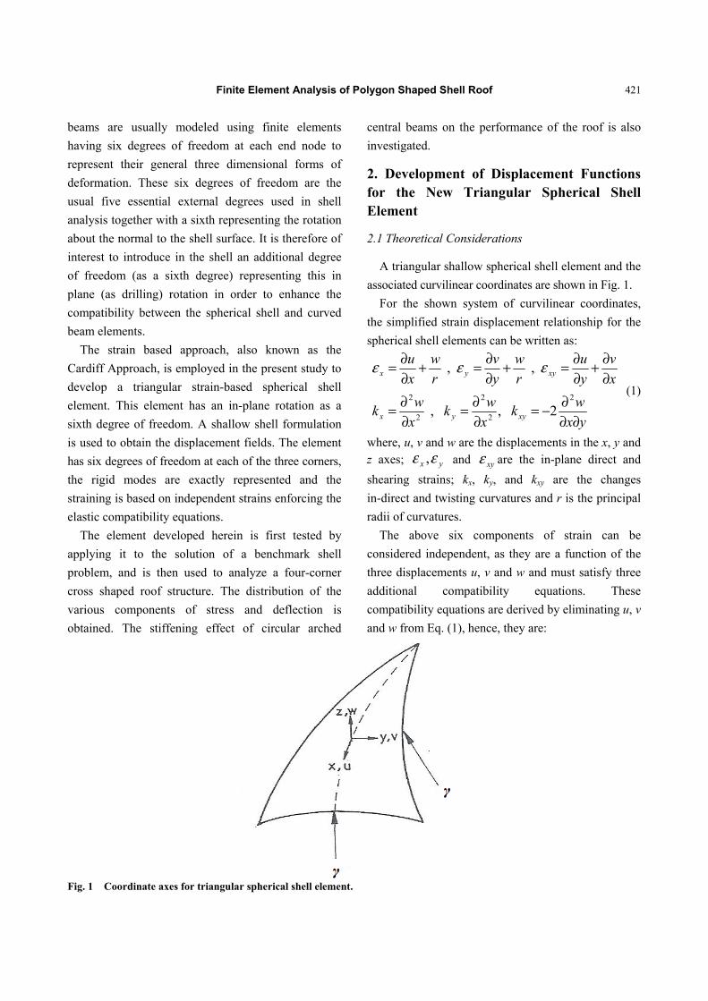
A triangular shallow spherical shell element and the
associated curvilinear coordinates are shown in Fig. 1.
For the shown system of curvilinear coordinates,
the simplified strain displacement relationship for the
spherical shell elements can be written as:
yx
wk
x
wk
x
wk
x
v
y
u
r
w
y
v
r
w
x
u
xyyx
xyyx
∂∂∂−=
∂∂=
∂∂=
∂∂+
∂∂=+
∂∂=+
∂∂=
2
2
2
2
2
2 , ,
, , εεε (1)
where, u, v and w are the displacements in the x, y and z axes; yx εε , and xyε are the in-plane direct and
shearing strains; kx, ky, and kxy are the changes
in-direct and twisting curvatures and r is the principal
radii of curvatures.
The above six components of strain can be
considered independent, as they are a function of the
three displacements u, v and w and must satisfy three
additional compatibility equations. These
compatibility equations are derived by eliminating u, v
and w from Eq. (1), hence, they are:
Fig. 1 Coordinate axes for triangular spherical shell element.
Finite Element Analysis of Polygon Shaped Shell Roof
422
2 2 2 2 2
2
0
/ 2 / 0
/ 2 / 0
x y xy x y
xy x
xy y
y x x y k r k r
k x k y
k y k x
ε ε ε∂ ∂ + ∂ ∂ − ∂ ∂ ∂ + + =
∂ ∂ − ∂ ∂ =
∂ ∂ − ∂ ∂ =
(2)
In order to keep the element as simple as possible
and to avoid the difficulties associated with internal
non-geometric degrees of freedom, the developed
element should possess six degrees of freedom at each
of the four corner nodes: u, v, w, θx, θy and φ. Thus,
the shape functions for a rectangular element should
contain 24 independent constants.
To obtain the displacement fields due to rigid body
movements, all the six strains given by Eq. (1) are
equated to zero and the resulting partial differential
equations are integrated to yield:
yaxaaw
xaar
y
r
xa
r
xya
r
yav
yaar
xya
r
x
r
ya
r
xau
3211
65
22
3211
643
2
211
22
22
2
++−=
−+
−−+−=
+++
−−−=
(3)
These displacement fields are due to the six
components of the rigid body displacements and are
represented in terms of the constants a1 to a6. If the
element has six degrees of freedom for each of the
three corner nodes, the displacement fields should be
represented by 18 independent constants. Having used
six constants for the representation of the rigid body
modes, the remaining 12 constants are available for
expressing the displacements due to the strains within
the element. These constants can be apportioned
among the strains in several ways. For the present
element, the following is proposed:
7 8
2 2 3
15 16 17
1
2 2 6
x a a y
y xy ya a a
r
ε = +
− + +
2 3 2
9 10 12 13 14
1
2 6 2y
x x x ya a x a a a
rε
= + − + +
(4)
11axy =ε
yaxaakx 141312 ++=
yaxaak y 171615 ++=
( )18 14 172 2xyk a a x a y= + +
Eq. (4) is derived by first assuming the
un-bracketed terms and adding the terms between
brackets to satisfy the compatibility condition
(Eq. (2)). It is then equated to the corresponding
expressions in terms of u, v and w from Eq. (1) and
the resulting equations are integrated to obtain:
−+−+
+++−+=
r
y
r
yxa
r
ya
r
yxa
r
xa
r
xa
ya
yaxyaxau
12424
6
2462232
18
4
16
3
14
4
13
3
1211
2
10872
−++++
−+++−=
r
x
r
xya
r
ya
r
xya
r
ya
r
xa
xaxyaya
xav
1242466
24
2232
18
4
17
3
16
3
15
4
1411109
2
82
(5)
262
2262
18
3
17
2
16
2
15
2
14
3
13
2
122
xya
ya
xya
ya
yxa
xa
xaw
−−−
−−−−=
Finite Element Analysis of Polygon Shaped Shell Roof
423
The complete displacement functions for the
element are obtained by adding the corresponding
expressions for u, v and w from Eqs. (3) and (5). The
translational degrees of freedom for the element are u,
v, w. The three rotations about the x, y and z axes are
given by:
22
2
18
2
17
1615
2
143
xa
ya
xyayax
aay
wx
−−
−−−=∂∂=θ
222 18
2
1614
2
13122
ya
yaxya
xaxaa
x
wy −−−−−=
∂∂=θ
−−−−
+−++−=
∂∂−
∂∂=
r
y
r
xa
r
ya
r
xa
yaxaar
xa
r
ya
y
u
x
v
44 6
66
2
1
22
18
3
16
3
14
108632φ (6)
The stiffness matrix K for the shell element is then
calculated in the usual manner, i.e.,
{ }1 1dT T v− − = K C B DB C (7)
where, B and D are the strain and elasticity matrices,
respectively, and C is the matrix relating the nodal
displacements to the constant a1 to a18.
3. Consistent Load Vector
The simplest method to establish an equivalent set
of nodal forces is the lumping process. An alternative
and more accurate approach for dealing with
distributed loads is the use of a consistent load vector
which is derived by equating the work done by the
distributed load through the displacement of the
element to the work done by the nodal generalized
loads through the nodal displacements. If a
rectangular shell element is acted upon by a
distributed load q per unit area in the direction of w,
the work done by this load is given by:
1 d da b
a b
P qw x y− −
= (8)
where, a and b are the projected half length of the
sides of the triangular element in the x and y directions,
respectively. If w is taken to be represented by:
{w} = [NT]{a}=[NT][C-1]{d} (9)
where, NT for the present element is given by (see Eqs.
(3) and (5)):
2 3 2T
2 2 3
[ 1, , ,0,0,0,0,0,0,0,0, , , ,2 6 2
]2 2 6 2
x x x yx y
y xy y xy
= − − − −
− − − −
N
{a} is the vector of the independent constants, 1[ ]−C is the inverse of the transformation matrix and
{d} is a vector of the nodal degrees of freedom. The
work done by the consistent nodal generalized force
through the nodal displacements {d} is given by:
T2 { } { }P d= F (10)
Hence, from Eqs. (8)-(10), the nodal forces are
obtained, i.e.:
{ } { }[ ] 1T d da b
T
a b
q a x y−
− −
= F N C N (11)
Eq. (11) gives the nodal forces for a single
element; and the nodal forces for the whole structure
are obtained by assembling the elements’ nodal
forces.
Finite Element Analysis of Polygon Shaped Shell Roof
424
4. Problems Considered
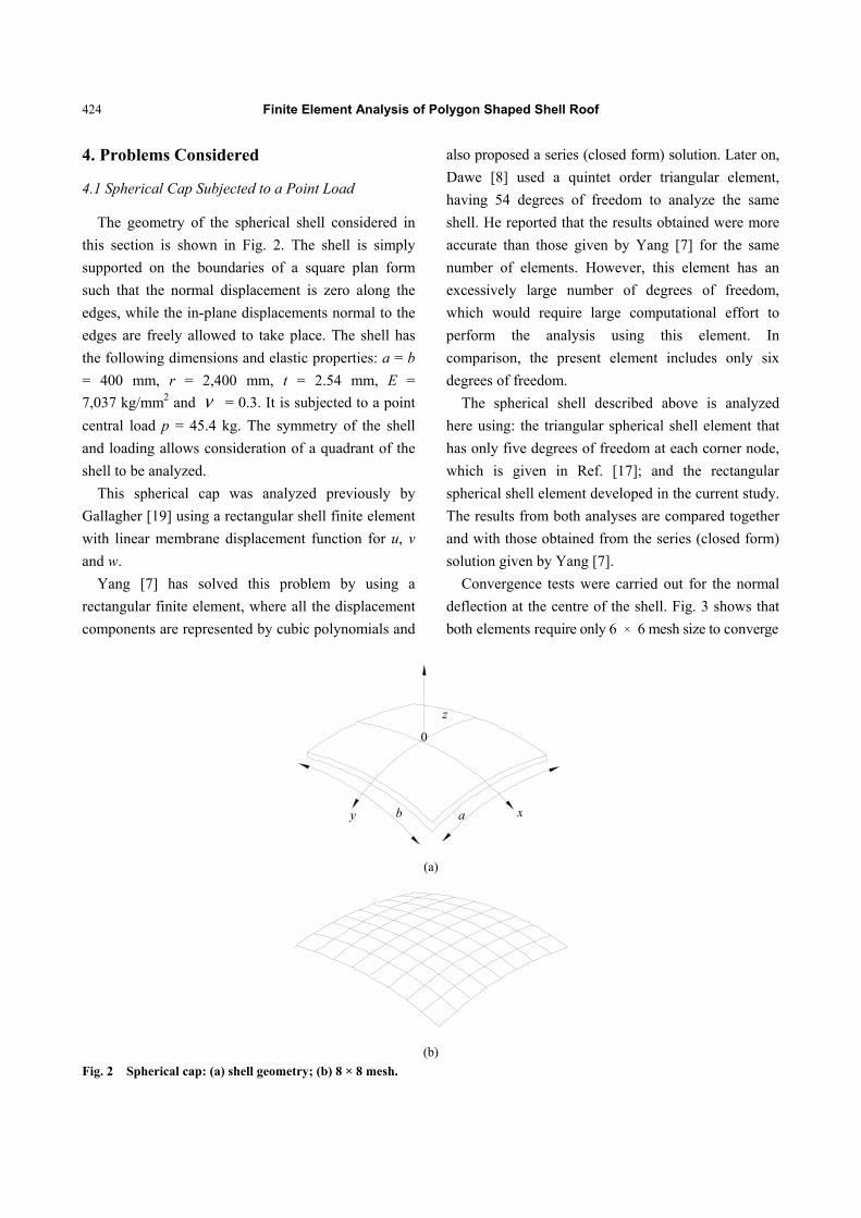
4.1 Spherical Cap Subjected to a Point Load
The geometry of the spherical shell considered in
this section is shown in Fig. 2. The shell is simply
supported on the boundaries of a square plan form
such that the normal displacement is zero along the
edges, while the in-plane displacements normal to the
edges are freely allowed to take place. The shell has
the following dimensions and elastic properties: a = b
= 400 mm, r = 2,400 mm, t = 2.54 mm, E =
7,037 kg/mm2 and ν = 0.3. It is subjected to a point
central load p = 45.4 kg. The symmetry of the shell
and loading allows consideration of a quadrant of the
shell to be analyzed.
This spherical cap was analyzed previously by
Gallagher [19] using a rectangular shell finite element
with linear membrane displacement function for u, v
and w.
Yang [7] has solved this problem by using a
rectangular finite element, where all the displacement
components are represented by cubic polynomials and
also proposed a series (closed form) solution. Later on,
Dawe [8] used a quintet order triangular element,
having 54 degrees of freedom to analyze the same
shell. He reported that the results obtained were more
accurate than those given by Yang [7] for the same
number of elements. However, this element has an
excessively large number of degrees of freedom,
which would require large computational effort to
perform the analysis using this element. In
comparison, the present element includes only six
degrees of freedom.
The spherical shell described above is analyzed
here using: the triangular spherical shell element that
has only five degrees of freedom at each corner node,
which is given in Ref. [17]; and the rectangular
spherical shell element developed in the current study.
The results from both analyses are compared together
and with those obtained from the series (closed form)
solution given by Yang [7].
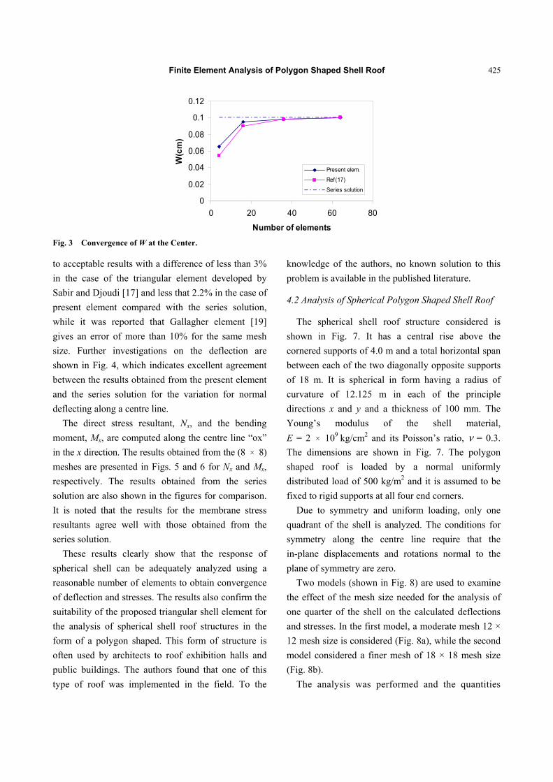
Convergence tests were carried out for the normal
deflection at the centre of the shell. Fig. 3 shows that
both elements require only 6 × 6 mesh size to converge
(a)
(b)
Fig. 2 Spherical cap: (a) shell geometry; (b) 8 × 8 mesh.
xy
z
0
ab
Finite Element Analysis of Polygon Shaped Shell Roof
425
0
0.02
0.04
0.06
0.08
0.1
0.12
0 20 40 60 80
Number of elements
W(c
m)
Present elem.
Ref(17)
Series solution
Fig. 3 Convergence of W at the Center.
to acceptable results with a difference of less than 3%
in the case of the triangular element developed by
Sabir and Djoudi [17] and less that 2.2% in the case of
present element compared with the series solution,
while it was reported that Gallagher element [19]
gives an error of more than 10% for the same mesh
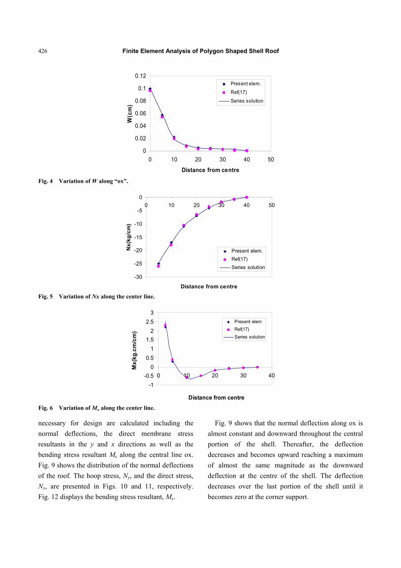
size. Further investigations on the deflection are
shown in Fig. 4, which indicates excellent agreement
between the results obtained from the present element
and the series solution for the variation for normal
deflecting along a centre line.
The direct stress resultant, Nx, and the bending
moment, Mx, are computed along the centre line “ox”
in the x direction. The results obtained from the (8 × 8)
meshes are presented in Figs. 5 and 6 for Nx and Mx,
respectively. The results obtained from the series
solution are also shown in the figures for comparison.
It is noted that the results for the membrane stress
resultants agree well with those obtained from the
series solution.
These results clearly show that the response of
spherical shell can be adequately analyzed using a
reasonable number of elements to obtain convergence
of deflection and stresses. The results also confirm the
suitability of the proposed triangular shell element for
the analysis of spherical shell roof structures in the
form of a polygon shaped. This form of structure is
often used by architects to roof exhibition halls and
public buildings. The authors found that one of this
type of roof was implemented in the field. To the
knowledge of the authors, no known solution to this
problem is available in the published literature.
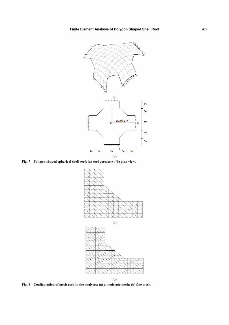
4.2 Analysis of Spherical Polygon Shaped Shell Roof
The spherical shell roof structure considered is
shown in Fig. 7. It has a central rise above the
cornered supports of 4.0 m and a total horizontal span
between each of the two diagonally opposite supports
of 18 m. It is spherical in form having a radius of
curvature of 12.125 m in each of the principle
directions x and y and a thickness of 100 mm. The
Young’s modulus of the shell material,
E = 2 × 10⁹ kg/cm2 and its Poisson’s ratio, ν = 0.3.
The dimensions are shown in Fig. 7. The polygon
shaped roof is loaded by a normal uniformly
distributed load of 500 kg/m2 and it is assumed to be
fixed to rigid supports at all four end corners.
Due to symmetry and uniform loading, only one
quadrant of the shell is analyzed. The conditions for
symmetry along the centre line require that the
in-plane displacements and rotations normal to the
plane of symmetry are zero.
Two models (shown in Fig. 8) are used to examine
the effect of the mesh size needed for the analysis of
one quarter of the shell on the calculated deflections
and stresses. In the first model, a moderate mesh 12 ×
12 mesh size is considered (Fig. 8a), while the second
model considered a finer mesh of 18 × 18 mesh size
(Fig. 8b).
The analysis was performed and the quantities
Finite Element Analysis of Polygon Shaped Shell Roof
426
0
0.02
0.04
0.06
0.08
0.1
0.12
0 10 20 30 40 50
Distance from centre
W(c
m)
Present elem.
Ref(17)
Series solution
Fig. 4 Variation of W along “ox”.
-30
-25
-20
-15
-10
-5
00 10 20 30 40 50
Distance from centre
Nx(
kg/c
m)
Present elem.Ref(17)Series solution
Fig. 5 Variation of Nx along the center line.
-1-0.5
00.5
11.5
22.5
3
0 10 20 30 40
Distance from centre
Mx(
kg.c
m/c
m)
Present elemRef(17)Series solution
Fig. 6 Variation of Mx along the center line.
necessary for design are calculated including the
normal deflections, the direct membrane stress
resultants in the y and x directions as well as the
bending stress resultant Mx along the central line ox.
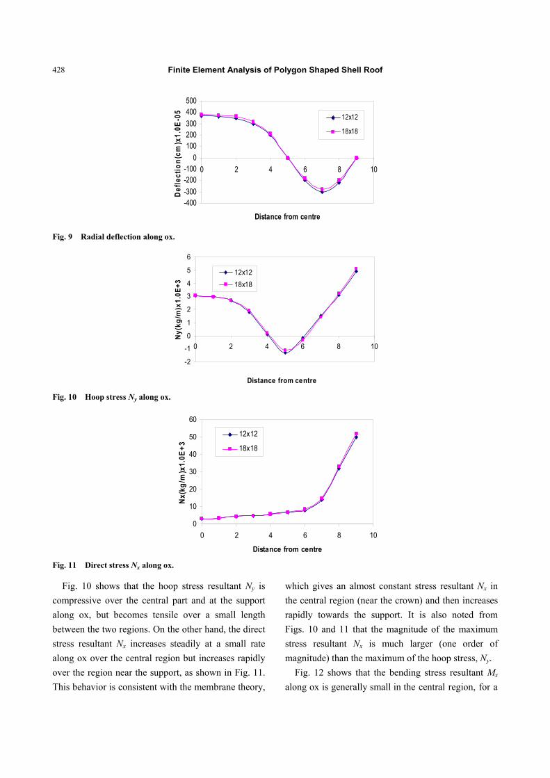
Fig. 9 shows the distribution of the normal deflections
of the roof. The hoop stress, Ny, and the direct stress,
Nx, are presented in Figs. 10 and 11, respectively.
Fig. 12 displays the bending stress resultant, Mx.
Fig. 9 shows that the normal deflection along ox is
almost constant and downward throughout the central
portion of the shell. Thereafter, the deflection
decreases and becomes upward reaching a maximum
of almost the same magnitude as the downward
deflection at the centre of the shell. The deflection
decreases over the last portion of the shell until it
becomes zero at the corner support.
Finite Element Analysis of Polygon Shaped Shell Roof
427
(a)
(b)
Fig. 7 Polygon shaped spherical shell roof: (a) roof geometry; (b) plan view.
(a)
(b)
Fig. 8 Configuration of mesh used in the analyses: (a) a moderate mesh; (b) fine mesh.
Finite Element Analysis of Polygon Shaped Shell Roof
428
-400-300-200-100
0100200300400500
0 2 4 6 8 10
Distance from centre
Defle
ctio
n(cm
)x1.
0E-0
5
12x12
18x18
Fig. 9 Radial deflection along ox.
-2
-1
0
1
2
3
4
5
6
0 2 4 6 8 10
Distance from centre
Ny(
kg/m
)x1.
0E+3
12x1218x18
Fig. 10 Hoop stress Ny along ox.
0
10
20
30
40
50
60
0 2 4 6 8 10
Distance from centre
Nx(
kg/m
)x1.
0E+3
12x12
18x18
Fig. 11 Direct stress Nx along ox.
Fig. 10 shows that the hoop stress resultant Ny is
compressive over the central part and at the support
along ox, but becomes tensile over a small length
between the two regions. On the other hand, the direct
stress resultant Nx increases steadily at a small rate
along ox over the central region but increases rapidly
over the region near the support, as shown in Fig. 11.
This behavior is consistent with the membrane theory,
which gives an almost constant stress resultant Nx in
the central region (near the crown) and then increases
rapidly towards the support. It is also noted from
Figs. 10 and 11 that the magnitude of the maximum
stress resultant Nx is much larger (one order of
magnitude) than the maximum of the hoop stress, Ny.
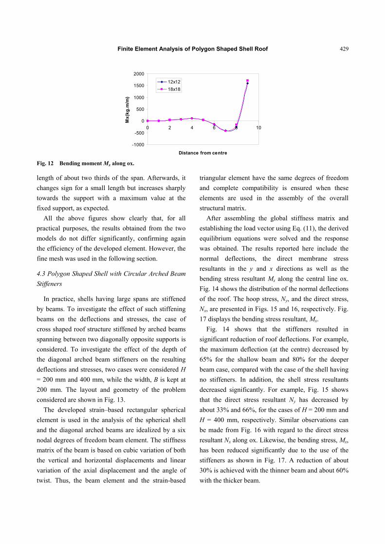
Fig. 12 shows that the bending stress resultant Mx
along ox is generally small in the central region, for a
Finite Element Analysis of Polygon Shaped Shell Roof
429
-1000
-500
0
500
1000
1500
2000
0 2 4 6 8 10
Distance from centre
Mx(
kg.m
/m)
12x1218x18
Fig. 12 Bending moment Mx along ox.
length of about two thirds of the span. Afterwards, it
changes sign for a small length but increases sharply
towards the support with a maximum value at the
fixed support, as expected.
All the above figures show clearly that, for all
practical purposes, the results obtained from the two
models do not differ significantly, confirming again
the efficiency of the developed element. However, the
fine mesh was used in the following section.
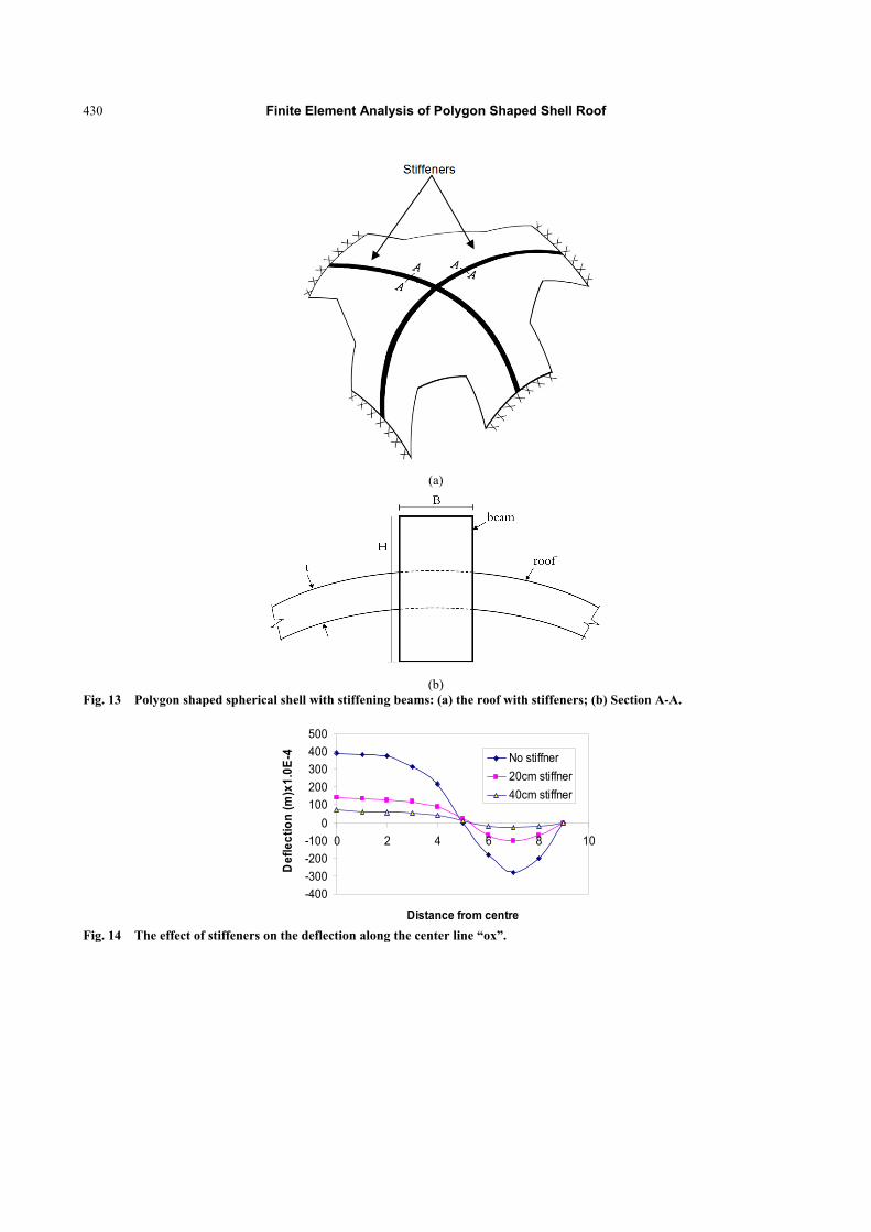
4.3 Polygon Shaped Shell with Circular Arched Beam
Stiffeners
In practice, shells having large spans are stiffened
by beams. To investigate the effect of such stiffening
beams on the deflections and stresses, the case of
cross shaped roof structure stiffened by arched beams
spanning between two diagonally opposite supports is
considered. To investigate the effect of the depth of
the diagonal arched beam stiffeners on the resulting
deflections and stresses, two cases were considered H
= 200 mm and 400 mm, while the width, B is kept at
200 mm. The layout and geometry of the problem
considered are shown in Fig. 13.
The developed strain–based rectangular spherical
element is used in the analysis of the spherical shell
and the diagonal arched beams are idealized by a six
nodal degrees of freedom beam element. The stiffness
matrix of the beam is based on cubic variation of both
the vertical and horizontal displacements and linear
variation of the axial displacement and the angle of
twist. Thus, the beam element and the strain-based
triangular element have the same degrees of freedom
and complete compatibility is ensured when these
elements are used in the assembly of the overall
structural matrix.
After assembling the global stiffness matrix and
establishing the load vector using Eq. (11), the derived
equilibrium equations were solved and the response
was obtained. The results reported here include the
normal deflections, the direct membrane stress
resultants in the y and x directions as well as the
bending stress resultant Mx along the central line ox.
Fig. 14 shows the distribution of the normal deflections
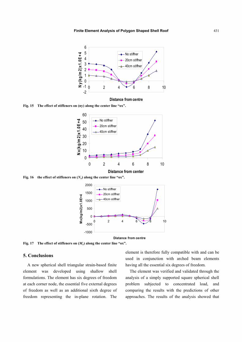
of the roof. The hoop stress, Ny, and the direct stress,
Nx, are presented in Figs. 15 and 16, respectively. Fig.
17 displays the bending stress resultant, Mx.
Fig. 14 shows that the stiffeners resulted in
significant reduction of roof deflections. For example,
the maximum deflection (at the centre) decreased by
65% for the shallow beam and 80% for the deeper
beam case, compared with the case of the shell having
no stiffeners. In addition, the shell stress resultants
decreased significantly. For example, Fig. 15 shows
that the direct stress resultant Ny has decreased by
about 33% and 66%, for the cases of H = 200 mm and
H = 400 mm, respectively. Similar observations can
be made from Fig. 16 with regard to the direct stress
resultant Nx along ox. Likewise, the bending stress, Mx,
has been reduced significantly due to the use of the
stiffeners as shown in Fig. 17. A reduction of about
30% is achieved with the thinner beam and about 60%
with the thicker beam.
Finite Element Analysis of Polygon Shaped Shell Roof
430
(a)
(b)
Fig. 13 Polygon shaped spherical shell with stiffening beams: (a) the roof with stiffeners; (b) Section A-A.
-400-300-200-100
0100200300400500
0 2 4 6 8 10
Distance from centre
Def
lect
ion
(m)x
1.0E
-4 No stiffner20cm stiffner40cm stiffner
Fig. 14 The effect of stiffeners on the deflection along the center line “ox”.
Finite Element Analysis of Polygon Shaped Shell Roof
431
-2-10123456
0 2 4 6 8 10
Distance from centre
Ny(
kg/m
2)x1
.0E+
4 No stiffner20cm stiffner40cm stiffner
Fig. 15 The effect of stiffeners on (ny) along the center line “ox”.
0
1020
30
4050
60
0 2 4 6 8 10
Distance from center
Nx(
kg/m
2)x1
.0E+
4 No stiffner20cm stiffner40cm stiffner
Fig. 16 the effect of stiffeners on (Nx) along the center line “ox”.
-1000
-500
0
500
1000
1500
2000
0 2 4 6 8 10
Distance from centre
Mx(
kg/m
2)x1
.0E+
4
No stiffner20cm stiffner40cm stiffner
Fig. 17 The effect of stiffeners on (Mx) along the center line “ox”.
5. Conclusions
A new spherical shell triangular strain-based finite
element was developed using shallow shell
formulations. The element has six degrees of freedom
at each corner node, the essential five external degrees
of freedom as well as an additional sixth degree of
freedom representing the in-plane rotation. The
element is therefore fully compatible with and can be
used in conjunction with arched beam elements
having all the essential six degrees of freedom.
The element was verified and validated through the
analysis of a simply supported square spherical shell
problem subjected to concentrated load, and
comparing the results with the predictions of other
approaches. The results of the analysis showed that
Finite Element Analysis of Polygon Shaped Shell Roof
432
reasonably accurate results were obtained even
modeling the shells using fewer elements compared to
other shell element types.
The developed element was then used in a finite
element model to analyze the response of polygon
shaped spherical roof structure. The distribution of
normal deflection and the various components of
stresses are evaluated. The results showed that this
type of shell roof exhibits large deflections at the
centre and large stresses at the corners because of its
non uniform shape and supporting conditions. The
response of the roof stiffened using diagonal arched
beams was also analyzed. The diagonally lined
stiffeners were found to considerably reduce the
deflections and stresses of cross shaped spherical roof
structures.
References
[1] Grafton, P. E., and Strome, D. R. “Analysis of Ax Symmetric Shells by the Direct Stiffness Method.” AIAA 1 (1): 2342-7.
[2] Jones, R. E., and Strome, D. R. 1966. “Direct Stiffness
Method Analysis of Shells of Revolution Utilizing
Curved Elements.” AIAA 4: 1519-25.
[3] Brebbia, C., and Connor, J. J. 1967. “Stiffness Matrix for
Shallow Rectangular Shell Element.” J. Eng. Mech. Div.
ASCE 93 EMS: 43-65.
[4] Cantin, G., and Clough, R. W. “A Curved Cylindrical
Shell Finite Element.” AIAA Journal 6: 1057-62.
[5] Sabir, A. B., and Lock, A. C. “A Curved Cylindrical Shell Finite Element.” Int. J. Mech. Sci. 14: 125.
[6] Cowper, G. R., Lindberg, G. M., and Olson, M. D. “A Shallow Shell Finite Element of Triangular Shape.” Int. J. Solids and Structures 6: 1133-56.
[7] Yang, T. Y. 1973. “High Order Rectangular Shallow Shell Finite Element.” J. Eng. Mech. Div. ASCE 99 EM1: 157.
[8] Dawe, D. J. 1975. “High Order Triangular Finite Element for Shell Analysis.” Int. J. Solids Structures 11: 1097-110.
[9] Ashwell, D. G., and Sabir, A. B. “A New Cylindrical Shell Finite Element Based on Simple Independent Strain Functions.” Int. J. Mech. Sci. 14: 171-83.
[10] Sabir, A. B., and Charchaechi, T. A. 1982. “Curved Rectangular and General Quadrilateral Shell Finite Elements for Cylindrical Shells.” The Math. of Finite Element and Appli. IV: 231-9.
[11] Sabir, A. B., and Ramadhani, F. 1985. “A Shallow Shell Finite Element for General Shell Analysis.” Variation Method In Engineering Proceedings of The 2nd International Conference, University of Southampton. England.
[12] Sabir, A. B., and Djoudi, M. S. 1990. “A Shallow Shell Triangular Finite Element for the Analysis of the Analysis of Hyperbolic Parabolic Shell Roof.” FEMCAD, Struct. Eng. and Optimization, 49-54.
[13] Mousa, A. I. 1998. “Finite Element Analysis of a Gable Roof.” Computational Structural Engineering in Practice 6 (7): 256-68.
[14] Mousa, A. I., and Kameshki, E. 2017. “Strain Based Finite Element for Analysis of Cylindrical Shell Dam.” American Journal of Engineering Research 6 (2): 119-28.
[15] Mousa, A. I., and Sabir, A. B. 1994. “Finite Element Analysis of Fluted Conical Shell Roof Structures.” Computational Structural Engineering in Practice 6 (2): 173-81.
[16] Sabir, A. B. 1997. “Strain Based Shallow Spherical Shell Element.” In Proc. Int. Conf on the Math. Finite elements and application, Brunel University, England.
[17] Sabir, A. B., and Djoudi, M. S. 1998. “A Shallow Shell Triangular Finite Element for the Analysis of Spherical Shells.” Structural Analysis J., PP51-57.
[18] Mousa, A. I., and Djoudi, M. S. 2015. “A Shallow Shell Finite Element for the Linear and Nonlinear Analysis of Spherical Shells.” International Journal of Civil and Environmental Engineering 15 (5): 24-9.
[19] Gallagher, R. H. 1966. “The Development and Evaluation of Matrix Methods for Thin Shell Structural Analysis.” Ph.D. thesis, State University of New York Buffalo.


![DESIGN AND ANALYSIS OF SPLIT RING RESONATOR BASED ...ictactjournals.in/paper/IJME_Vol_4_Iss_4_Paper_4_687_692.pdf · patch antenna [17], Polygon patch antenna [18], W-shaped microstrip](https://img.pdfslide.us/doc/110x75/5ffd0bf10bbfba4951293444/design-and-analysis-of-split-ring-resonator-based-patch-antenna-17-polygon.jpg)