Embed Size (px)
Citation preview
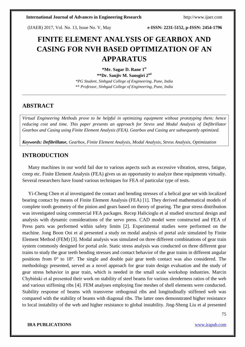
International Journal of Advances in Engineering Research http://www.ijaer.com
(IJAER) 2017, Vol. No. 13, Issue No. V, May e-ISSN: 2231-5152, p-ISSN: 2454-1796
75
IRA PUBLICATIONS www.irapub.com
FINITE ELEMENT ANALYSIS OF GEARBOX AND
CASING FOR NVH BASED OPTIMIZATION OF AN
APPARATUS
*Mr. Sagar D. Rane 1st
**Dr. Sanjiv M. Sansgiri 2nd
*PG Student, Sinhgad College of Engineering, Pune, India
** Professor, Sinhgad College of Engineering, Pune, India
ABSTRACT
Virtual Engineering Methods prove to be helpful in optimizing equipment without prototyping them; hence
reducing cost and time. This paper presents an approach for Stress and Modal Analysis of Defibrillator
Gearbox and Casing using Finite Element Analysis (FEA). Gearbox and Casing are subsequently optimized.
Keywords: Defibrillator, Gearbox, Finite Element Analysis, Modal Analysis, Stress Analysis, Optimization
INTRODUCTION
Many machines in our world fail due to various aspects such as excessive vibration, stress, fatigue,
creep etc. Finite Element Analysis (FEA) gives us an opportunity to analyze these equipments virtually.
Several researchers have found various techniques for FEA of particular type of tests.
Yi-Cheng Chen et al investigated the contact and bending stresses of a helical gear set with localized
bearing contact by means of Finite Element Analysis (FEA) [1]. They derived mathematical models of
complete tooth geometry of the pinion and gears based on theory of gearing. The gear stress distribution
was investigated using commercial FEA packages. Recep Halicioglu et al studied structural design and
analysis with dynamic considerations of the servo press. CAD model were constructed and FEA of
Press parts was performed within safety limits [2]. Experimental studies were performed on the
machine. Jong Boon Ooi et al presented a study on modal analysis of portal axle simulated by Finite
Element Method (FEM) [3]. Modal analysis was simulated on three different combinations of gear train
system commonly designed for portal axle. Static stress analysis was conducted on three different gear
trains to study the gear teeth bending stresses and contact behavior of the gear trains in different angular
positions from 0° to 18°. The single and double pair gear teeth contact was also considered. The
methodology presented, served as a novel approach for gear train design evaluation and the study of
gear stress behavior in gear train, which is needed in the small scale workshop industries. Marcin
Chybiński et al presented their work on stability of steel beams for various slenderness ratios of the web
and various stiffening ribs [4]. FEM analyses employing fine meshes of shell elements were conducted.
Stability response of beams with transverse orthogonal ribs and longitudinally stiffened web was
compared with the stability of beams with diagonal ribs. The latter ones demonstrated higher resistance
to local instability of the web and higher resistance to global instability. Jing-Sheng Liu et al presented
International Journal of Advances in Engineering Research http://www.ijaer.com
(IJAER) 2017, Vol. No. 13, Issue No. V, May e-ISSN: 2231-5152, p-ISSN: 2454-1796
76
IRA PUBLICATIONS www.irapub.com
an optimization procedure for composite panel structures with stiffening ribs [5]. The procedure
employs standard Finite Element based structural analysis, structural system profile analysis, and multi-
factor optimization techniques to predict the optimum structural design. A composite antenna reflector
structure in space environment was optimized. Laminate, sandwich configuration and rib shape in the
structure were optimized in this application. H. Hosseini-Toudeshky et al developed an approximate
method for design of bead stiffened composite panels [6]. In their research, finite elements based
buckling analyses were performed for various panels with different beads spacing, beads depths, beads
radiuses and panels lengths. The analysis of results has shown that the beads spacing is of chief
significance as far as the panel buckling load is concerned. H. Hosseini-Toudeshky et al again presented
a study on new methods of stabilizing techniques used for the panels, webs and ribs of composite
structures [7]. They performed parametric study to access the effects of important design parameters
such as, bead length, number of beads, bead radius, bead depth and bead spacing on the initial buckling
load of the panels. The results show that there is optimum bead spacing for each panel containing more
than one bead, which can be estimated using a simple equation.
In this paper, an approach for Stress and Modal analyses of Defibrillator Casing and Geartrain will
be presented using HyperWorks, and Optimization of the Casing and Gearbox apparatus will be carried
out with the aim of reducing Stress, Noise, Vibrations and Harshness.
GEARTRAIN STRESS ANALYSIS
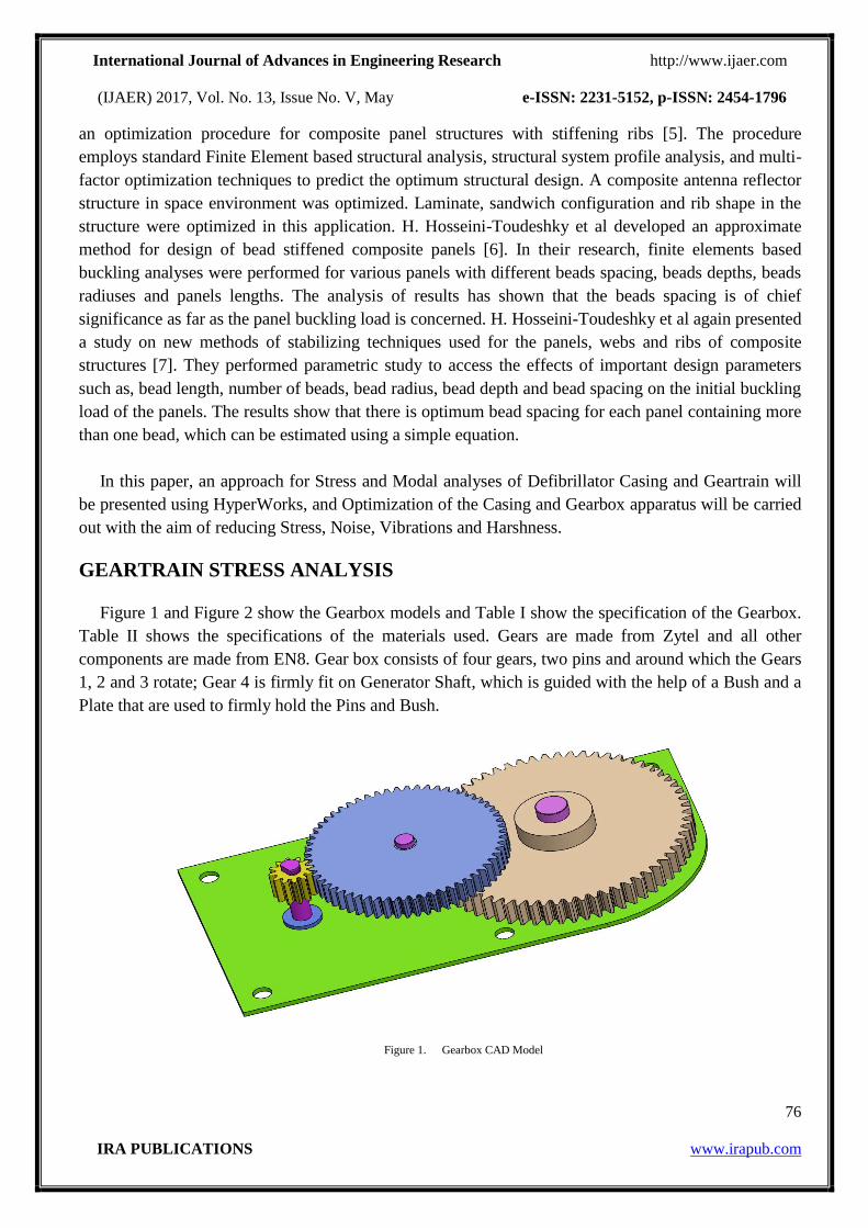
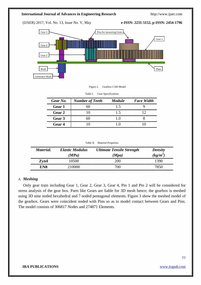
Figure 1 and Figure 2 show the Gearbox models and Table I show the specification of the Gearbox.
Table II shows the specifications of the materials used. Gears are made from Zytel and all other
components are made from EN8. Gear box consists of four gears, two pins and around which the Gears
1, 2 and 3 rotate; Gear 4 is firmly fit on Generator Shaft, which is guided with the help of a Bush and a
Plate that are used to firmly hold the Pins and Bush.
Figure 1. Gearbox CAD Model
International Journal of Advances in Engineering Research http://www.ijaer.com
(IJAER) 2017, Vol. No. 13, Issue No. V, May e-ISSN: 2231-5152, p-ISSN: 2454-1796
77
IRA PUBLICATIONS www.irapub.com
Figure 2. Gearbox CAD Model
Table I. Gear Specifications
Gear No. Number of Teeth Module Face Width
Gear 1 60 1.5 9
Gear 2 10 1.5 12
Gear 3 60 1.0 8
Gear 4 10 1.0 10
Table II. Material Properties
Material. Elastic Modulus
(MPa)
Ultimate Tensile Strength
(Mpa)
Density
(kg/m3)
Zytel 10500 200 1390
EN8 210000 700 7850
A. Meshing
Only gear train including Gear 1, Gear 2, Gear 3, Gear 4, Pin 1 and Pin 2 will be considered for
stress analysis of the gear box. Parts like Gears are liable for 3D mesh hence; the gearbox is meshed
using 3D nine noded hexahedral and 7 noded pentagonal elements. Figure 3 show the meshed model of
the gearbox. Gears were coincident noded with Pins so as to model contact between Gears and Pins.
The model consists of 306817 Nodes and 274871 Elements.
Gear 1
Gear 2
Gear 3
Gear 4
Bush
Generator Shaft
Plate
Pins for mounting Gears
International Journal of Advances in Engineering Research http://www.ijaer.com
(IJAER) 2017, Vol. No. 13, Issue No. V, May e-ISSN: 2231-5152, p-ISSN: 2454-1796
78
IRA PUBLICATIONS www.irapub.com
Figure 3. Gearbox Finite Element Model
B. Boundary Conditions
Capturing proper boundary conditions is an important criterion for getting good results. To get an
idea about the boundary conditions for stress analysis of a geartrain using HyperWorks, a small model
was considered as shown in Figure 4. Rigid Body Elements (RBE2) were used as shown in Figure 5 for
constraining the motion of Gear around Y axis and also imposing Torque. 100 Nmm torque was given
at the independent node and one tooth of the Gear was fully constrained using SPCs as shown in Figure
6. Satisfactory reaction force was obtained at the constraints on tooth of Gear.
Figure 4. Small Model
Figure 5. Use of RBE2 Elements to Impose Torque
Independent node so as define constraints and torque
Rigids to maintain same constraints as centre
International Journal of Advances in Engineering Research http://www.ijaer.com
(IJAER) 2017, Vol. No. 13, Issue No. V, May e-ISSN: 2231-5152, p-ISSN: 2454-1796
79
IRA PUBLICATIONS www.irapub.com
Figure 6. Constraints
C. Results
Gear to gear contact was simulated using RBE2 as shown in Figure 7. The Geartrain was analyzed
with same approach as discussed. 15000 Nmm torque was imposed on Pin 1 about Y direction, Pin 2
was free to rotate around Y axis and Generator Shaft was kept stationary.
Figure 7. Contact between Gear 1 and Gear 2
The result for stress analysis of gear train is shown in Figure 8. Maximum stress is found to be 78.4
MPa on Gear 1 which is less than the yield strength of the Gear material. Geartrain was hence found to
be safe under 15000 Nmm torque.
Figure 8. Stress Analysis Result
GEARBOX MODAL ANALYSIS
Constraints to obtain support
reactions due to torque.
Constrains to rotate only
around Y-axis and 100 Nmm
Torque
Rigids used to simulate
contact between gears.
International Journal of Advances in Engineering Research http://www.ijaer.com
(IJAER) 2017, Vol. No. 13, Issue No. V, May e-ISSN: 2231-5152, p-ISSN: 2454-1796
80
IRA PUBLICATIONS www.irapub.com
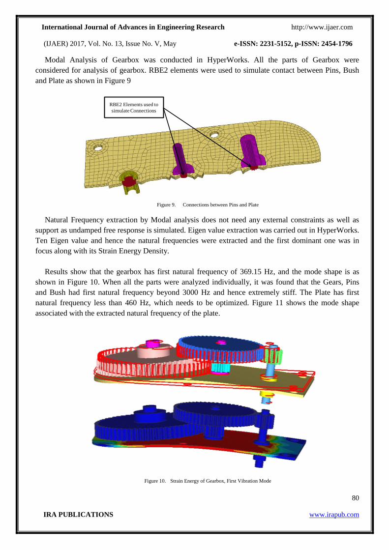
Modal Analysis of Gearbox was conducted in HyperWorks. All the parts of Gearbox were
considered for analysis of gearbox. RBE2 elements were used to simulate contact between Pins, Bush
and Plate as shown in Figure 9
Figure 9. Connections between Pins and Plate
Natural Frequency extraction by Modal analysis does not need any external constraints as well as
support as undamped free response is simulated. Eigen value extraction was carried out in HyperWorks.
Ten Eigen value and hence the natural frequencies were extracted and the first dominant one was in
focus along with its Strain Energy Density.
Results show that the gearbox has first natural frequency of 369.15 Hz, and the mode shape is as
shown in Figure 10. When all the parts were analyzed individually, it was found that the Gears, Pins
and Bush had first natural frequency beyond 3000 Hz and hence extremely stiff. The Plate has first
natural frequency less than 460 Hz, which needs to be optimized. Figure 11 shows the mode shape
associated with the extracted natural frequency of the plate.
Figure 10. Strain Energy of Gearbox, First Vibration Mode
RBE2 Elements used to
simulate Connections
International Journal of Advances in Engineering Research http://www.ijaer.com
(IJAER) 2017, Vol. No. 13, Issue No. V, May e-ISSN: 2231-5152, p-ISSN: 2454-1796
81
IRA PUBLICATIONS www.irapub.com
Figure 11. Energy of Plate, First Vibration Mode
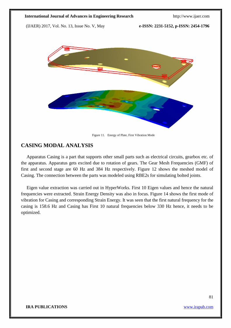
CASING MODAL ANALYSIS
Apparatus Casing is a part that supports other small parts such as electrical circuits, gearbox etc. of
the apparatus. Apparatus gets excited due to rotation of gears. The Gear Mesh Frequencies (GMF) of
first and second stage are 60 Hz and 384 Hz respectively. Figure 12 shows the meshed model of
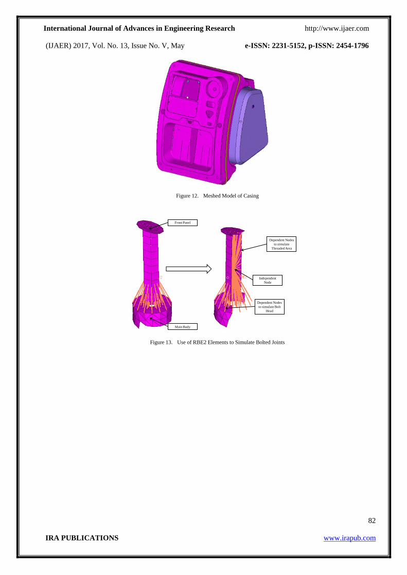
Casing. The connection between the parts was modeled using RBE2s for simulating bolted joints.
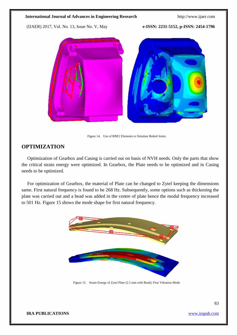
Eigen value extraction was carried out in HyperWorks. First 10 Eigen values and hence the natural
frequencies were extracted. Strain Energy Density was also in focus. Figure 14 shows the first mode of
vibration for Casing and corresponding Strain Energy. It was seen that the first natural frequency for the
casing is 158.6 Hz and Casing has First 10 natural frequencies below 330 Hz hence, it needs to be
optimized.
International Journal of Advances in Engineering Research http://www.ijaer.com
(IJAER) 2017, Vol. No. 13, Issue No. V, May e-ISSN: 2231-5152, p-ISSN: 2454-1796
82
IRA PUBLICATIONS www.irapub.com
Figure 12. Meshed Model of Casing
Figure 13. Use of RBE2 Elements to Simulate Bolted Joints
Front Panel
Main Body
Independent
Node
Dependent Nodes
to simulate Bolt
Head
Dependent Nodes
to simulate
Threaded Area
International Journal of Advances in Engineering Research http://www.ijaer.com
(IJAER) 2017, Vol. No. 13, Issue No. V, May e-ISSN: 2231-5152, p-ISSN: 2454-1796
83
IRA PUBLICATIONS www.irapub.com
Figure 14. Use of RBE2 Elements to Simulate Bolted Joints
OPTIMIZATION
Optimization of Gearbox and Casing is carried out on basis of NVH needs. Only the parts that show
the critical strain energy were optimized. In Gearbox, the Plate needs to be optimized and in Casing
needs to be optimized.
For optimization of Gearbox, the material of Plate can be changed to Zytel keeping the dimensions
same. First natural frequency is found to be 268 Hz. Subsequently, some options such as thickening the
plate was carried out and a bead was added in the centre of plate hence the modal frequency increased
to 501 Hz. Figure 15 shows the mode shape for first natural frequency.
Figure 15. Strain Energy of Zytel Plate (2.5 mm with Bead); First Vibration Mode
International Journal of Advances in Engineering Research http://www.ijaer.com
(IJAER) 2017, Vol. No. 13, Issue No. V, May e-ISSN: 2231-5152, p-ISSN: 2454-1796
84
IRA PUBLICATIONS www.irapub.com
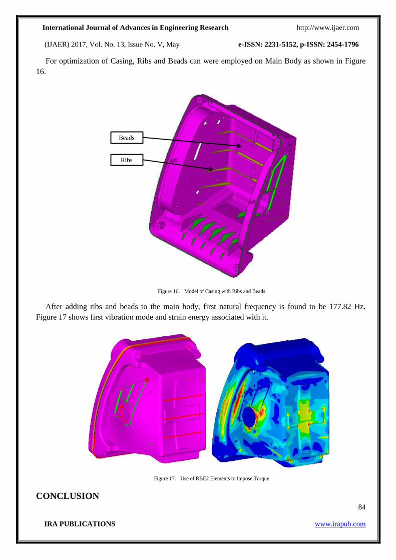
For optimization of Casing, Ribs and Beads can were employed on Main Body as shown in Figure
16.
Figure 16. Model of Casing with Ribs and Beads
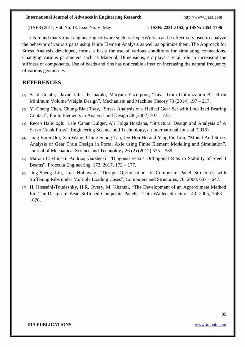
After adding ribs and beads to the main body, first natural frequency is found to be 177.82 Hz.
Figure 17 shows first vibration mode and strain energy associated with it.
Figure 17. Use of RBE2 Elements to Impose Torque
CONCLUSION
Beads
Ribs
International Journal of Advances in Engineering Research http://www.ijaer.com
(IJAER) 2017, Vol. No. 13, Issue No. V, May e-ISSN: 2231-5152, p-ISSN: 2454-1796
85
IRA PUBLICATIONS www.irapub.com
It is found that virtual engineering software such as HyperWorks can be effectively used to analyze
the behavior of various parts using Finite Element Analysis as well as optimize them. The Approach for
Stress Analysis developed, forms a basis for use of various conditions for simulating connections.
Changing various parameters such as Material, Dimensions, etc plays a vital role in increasing the
stiffness of components. Use of beads and ribs has noticeable effect on increasing the natural frequency
of various geometries.
REFERENCES
[1] Sa'id Golabi, Javad Jafari Fesharaki, Maryam Yazdipoor, “Gear Train Optimization Based on
Minimum Volume/Weight Design”, Mechanism and Machine Theory 73 (2014) 197 – 217.
[2] Yi-Cheng Chen, Chung-Biau Tsay, “Stress Analysis of a Helical Gear Set with Localized Bearing
Contact”, Finite Elements in Analysis and Design 38 (2002) 707 – 723.
[3] Recep Halicioglu, Lale Canan Dulger, Ali Tolga Bozdana, “Structural Design and Analysis of A
Servo Crank Press”, Engineering Science and Technology, an International Journal (2016)
[4] Jong Boon Ooi, Xin Wang, Ching Seong Tan, Jee-Hou Ho and Ying Pio Lim, “Modal And Stress
Analysis of Gear Train Design in Portal Axle using Finite Element Modeling and Simulation”,
Journal of Mechanical Science and Technology 26 (2) (2012) 575 – 589.
[5] Marcin Chybiński, Andrzej Garstecki, “Diagonal versus Orthogonal Ribs in Stability of Steel I
Beams”, Procedia Engineering, 172, 2017, 172 – 177.
[6] Jing-Sheng Liu, Len Hollaway, “Design Optimisation of Composite Panel Structures with
Stiffening Ribs under Multiple Loading Cases”, Computers and Structures, 78, 2000, 637 – 647.
[7] H. Hosseini-Toudeshky, H.R. Ovesy, M. Kharazi, “The Development of an Approximate Method
for, The Design of Bead-Stiffened Composite Panels”, Thin-Walled Structures 43, 2005, 1663 –
1676.


![Welcome [ntrs.nasa.gov] · Welcome https: //ntrs.nasa.gov ... RBE3 vs RBE2 Components ... – Evaluated use of RBE3 elements Change from RBE3 to RBE2 elements had less effect than](https://img.pdfslide.us/doc/110x75/5b5e83fe7f8b9a553d8cb160/welcome-ntrsnasagov-welcome-https-ntrsnasagov-rbe3-vs-rbe2-components.jpg)