Embed Size (px)
Citation preview

INTERNATIONAL JOURNAL OF PROFESSIONAL ENGINEERING STUDIES Volume VIII /Issue 2 / JAN 2017
IJPRES
FINITE ELEMENT ANALYSIS OF FATIGUE OVER DAMGED COMPOSITES UNDER CRACK PROPAGATION
1 MUTLOORI EZEKIEL, 2 D.V. SUBBARAO
1 Pg Scholar, Department of MECH, Malla Reddy College Of Engineering And Technology
(Sponsored by C.M.R. Educational society) Autonomous Institution – UGC, Govt. of India, NAAC-A Grade,
Accredited by AICTE-NBA, Affiliated to JNTUH Hyderabad, Maisammaguda, Dhulapally post, Secunderabad-
500100 2 Assistant Professor, Department of MECH, Malla Reddy College Of Engineering And Technology
(Sponsored by C.M.R. Educational society) Autonomous Institution – UGC, Govt. of India, NAAC-A Grade,
Accredited by AICTE-NBA, Affiliated to JNTUH Hyderabad, Maisammaguda, Dhulapally post, Secunderabad-
500100
ABSTRACT
Now a day’s composites are being widely used in
many applications. Composites are blend of two or
more materials forming a component. Fatigue life is
an important consideration used by the designers.
Each and every component designated with fatigue
number. Fatigue is a damage which is caused due to
continuous loading and unloading, certainly known
as cyclic loading. Continuous fiber reinforced metal
matrix composites are projected for use in high
temperature stiffness critical part that will be
subjected to cyclic loadings. This project presents a
general overview of the fatigue behavior of
composite fiber such as carbon fiber and Glass fiber
and presents the Crack propagation in composite
fiber. A numerical study was performed to
investigate the dynamic crack propagation on carbon
fiber and glass fiber reinforced composite plates
utilizing the finite element method. A rectangular
plate of uniform thickness, which had a propagating
crack, was used for the study. The plate was a
unidirectional composite panel and the load was
applied in the longitudinal direction of the composite
plate. The objective of the study was to examine the
effect of different composite material properties,
different ply orientations and densities on the
fracture. The metal matrix composite are grouped in
four types 1) Matrix dominated 2) Fiber dominated 3)
Self-similar damage 4) Fiber/matrix interfacial
failure. These four types of damage will be discussed
and illustrated by example with the emphasis on the
fatigue of un-notched laminates. The Crack
propagation and Fatigue life of the composite fiber is
analyzed by using MSC Fatigue software.
The experiment was performed on one of the
aluminum plate in order to investigate the Dynamic
crack propagation on the rectangular plate by using
composite fiber such as carbon fiber and glass fiber
validate the results of numerical simulation.
Introduction To Composites
Composite material is a material composed of two
or more distinct phases matrix phase and dispersed
phase and having bulk properties different properties
from those of any of the constituents.
Classification Of Composites:
Composites are classified into 3 groups namely
1. Particle Reinforced Composites.
2. Fiber Reinforced Composites.
INTERNATIONAL JOURNAL OF PROFESSIONAL ENGINEERING STUDIES Volume VIII /Issue 2 / JAN 2017
IJPRES
3. Sandwichpanel composites.
1. Particle Reinforced Composites are sub divided
into:
a) Large Particle composites.
b) Dispersion strengthened Composites.
2. Fiber Reinforced Composites are sub divided into:
a) Continuous and Aligned fiber Composites
b) Discontinuous and Randomly Oriented fiber
Composites.
3. Structural Composites are sub divided into:
a) Laminar Composites.
b) Sandwich Panels.
Structural-Composites
A structural composite is normally composed of both
homogeneous and composite materials, the properties
of which depend not only the properties of the
constituent materials but also on the geometrical
design of the most common structural composites;
only a relatively superficial examination is offered
here for them.
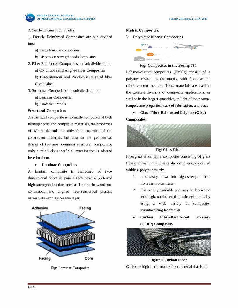
Laminar Composites
A laminar composite is composed of two-
dimensional sheet or panels they have a preferred
high-strength direction such as I found in wood and
continuous and aligned fiber-reinforced plastics
varies with each successive layer.
Fig: Laminar Composite
Matrix Composites:
Polymeric Matrix Composites
Fig: Composites in the Boeing 787
Polymer-matrix composites (PMCs) consist of a
polymer resin 1 as the matrix, with fibers as the
reinforcement medium. These materials are used in
the greatest diversity of composite applications, as
well as in the largest quantities, in light of their room-
temperature properties, ease of fabrication, and cost.
Glass Fiber-Reinforced Polymer (Gfrp)
Composites:
Fig: Glass Fiber
Fiberglass is simply a composite consisting of glass
fibers, either continuous or discontinuous, contained
within a polymer matrix.
1. It is easily drawn into high-strength fibers
from the molten state.
2. It is readily available and may be fabricated
into a glass-reinforced plastic economically
using a wide variety of composite-
manufacturing techniques.
Carbon Fiber-Reinforced Polymer
(CFRP) Composites
Figure 6 Carbon Fiber
Carbon is high-performance fiber material that is the

INTERNATIONAL JOURNAL OF PROFESSIONAL ENGINEERING STUDIES Volume VIII /Issue 2 / JAN 2017
IJPRES
most commonly used reinforcement in advanced (i.e.,
nonfiberglass) polymer-matrix composites. The
reasons for this are as follows:
1. Carbon fiber has the highest specific
modulus and specific strength of all
reinforcing fiber materials.
2. They retain their high-tensile modulus and
high strength at elevated temperatures;
high-temperature oxidation, however, may
be a problem.
Aramid Fiber-Reinforced Polymer
Composites
Fig: Aramid composite
Aramid fibers are high-strength, high-modulus
materials that were introduced in the early 1970s.
They are especially desirable for their outstanding
strength-to weight ratios, which are superior to
metals.
Ceramic-Matrix Composites
Fig: Ceramic Matrix Composite
Ceramic matrix composites (CMCs) provide high
temperature oxidation stability relative to metals and
enhanced toughness relative to monolithic ceramics.
Ultra met offers durable, refractory CMCs that
survive the severe environments of propulsion and
thermal management systems. Because they are
fabricated through a rapid melt infiltration process,
Ultra met CMCs are far less costly than composites.
Small particles of partially stabilized zirconia are
dispersed within the matrix material, often A12O3 or
ZrO2 itself. Typically, CaO, MgO, Y2O3, and CeO
are used as stabilizers.
Properties:
Mechanics
The physical properties of composite materials are
generally not isotropic (independent of direction of
applied force) in nature, but rather are typically
anisotropic (different depending on the direction of
the applied force or load).
For the special case of orthogonal isotropy, there are
three different material property constants for each of
Young’s Modulus, Shear Modulus and the Poisson’s
ratio – a total of 9 constants to describe the
relationship between force/ moments and
strains/curvatures. Techniques that take advantage of
the anisotropic properties of the materials include
mortise and tenon joints (in natural composites such
as wood) Pi joints in synthetic composites.
Failure
Shock, impact, or repeated cyclic stresses can cause
the damage to the composites.
Resin Systems
Depending on the particular thermoplastic material
used, thermoplastic matrix components can, however,
be used over a wide range of temperature from 100°c
to 3000°c. The advantages of thermoplastic matrices
are their improved fracture toughness over the thermo
set matrix and their potential of much lower cost in
the manufacturing of finished composites. For the
purpose of a simple classification, we may divide the
thermo set polymers into five categories. Polyester
resin,

INTERNATIONAL JOURNAL OF PROFESSIONAL ENGINEERING STUDIES Volume VIII /Issue 2 / JAN 2017
IJPRES
(i) Polyester resins,
(ii) Epoxy resin,
(iii) Vinyl ester resin,
(iv) Phenolic resin and
(v) High performance resins.
Different Types Of Fuselage Skin:
The fuselage is an aircraft's main body section that
holds crew and passengers or cargo. In single-engine
aircraft it will usually contain an engine, although in
some amphibious aircraft the single engine is
mounted on a pylon attached to the fuselage which in
turn is used as a floating hull.
There are three types of fuselage structure:
Truss type structure:
This type of structure is still in use in many
lightweight aircraft using welded steel tube trusses. A
box truss fuselage structure can also be built out of
wood often covered with plywood as can be seen on
this Ibis canard fuselage.
Fig: Truss Type Structure
Monocoque structure:
Monocoque is a structural approach that supports
loads through an object's external skin, similar to an
egg shell. The term is also used to indicate a structure
in which the skin provides the main structural
support, although this is rare and is usually confused
with either semi-monocoque or a unibody. The word
monocoque comes from the Greek for single (mono)
and French for shell (coque).
Semi-Monocoque Structure:
This is the preferred method of constructing an all-
aluminum fuselage. First, a series of frames in the
shape of the fuselage cross sections are held in
position on a rigid fixture. These frames are then
joined with lightweight longitudinal elements called
stringers.
Fig: Semi Monocoque Structure
Different Types Of Rivets used:
Rivets
Before modern welding techniques came into
common use, riveting was one of the most common
methods for joining sheet metal. Since the advent of
the new welding techniques and modern machines
that form seams on sheet metal, riveted seams are not
so common in modern sheet metal work.
Fig: Rivets
Riveting
Riveting may be done by hand or by machine. When
the job is performed by hand, as is usually the case in
sheet metal work, it is done with a hammer and rivet
set.
Rivet Sizes
The size of rivets is determined by the
weight of 1,000 rivets i.e. 1N. Rivets weigh 1 N. per
thousand, 2 N. rivets weigh 2 N. per thousand.
Flathead rivets vary in diameter from 3/32" to 7/16"
in steps of 1/32". Other rivets vary in size with 1/8"
INTERNATIONAL JOURNAL OF PROFESSIONAL ENGINEERING STUDIES Volume VIII /Issue 2 / JAN 2017
IJPRES
and 3/16" snaphead rivets being the most popular in
the sheet metal shop.
Fig: Rivet Sizes
Types of Rivet and Rivet-Head
The way in which thin material is joined to thick
material with countersunk rivets.
Always use the correct rivet for a particular metal to
be riveted. When riveting aluminium, for example,
use aluminium rivets; and when riveting copper use
copper rivets.
Fig: Standard Types of Rivet Heads
Fig: Countersunk Riveting Of Thin Material To
Thick Material
Defects in Riveted Joint
When making joints with rivets, the following points
should be followed to prevent many common defects:
1. Use The correct allowance for edge clearance and
pitch when marking out.
2. Use the proper type of rivet as specified on the
drawing.
3. Use rivets of the correct length.
Properties Of Typical Composite Materials
Various types of composite materials are possible by
choosing different constituents mixed in different
proportions. Those composites have higher specific
modulus and higher specific strength than steel.
Fiber properties dictate the stiffness of
unidirectional composites. For higher strength of
unidirectional composites, the ultimate strain is
generally lower at failure. For some composites, the
increase of stiffness has resulted in lowering the
strength zth stress-strain curve for unidirectional
composites in general is linear.
Advantages Of Composites:
1) A higher performance for a give weight
leads to fuel savings.
2) Part count is reduced.
3) Production cost is reduced. Composites
may be made by a wide range of processes.
Disadvantages Of Composites:
1) Composites are more brittle than wrought
metals and thus are more easily damaged.
Current Applications Ofcompositesin Aerospace:
The application of composites in place of
metal requires different approaches to the design and
service of structural components
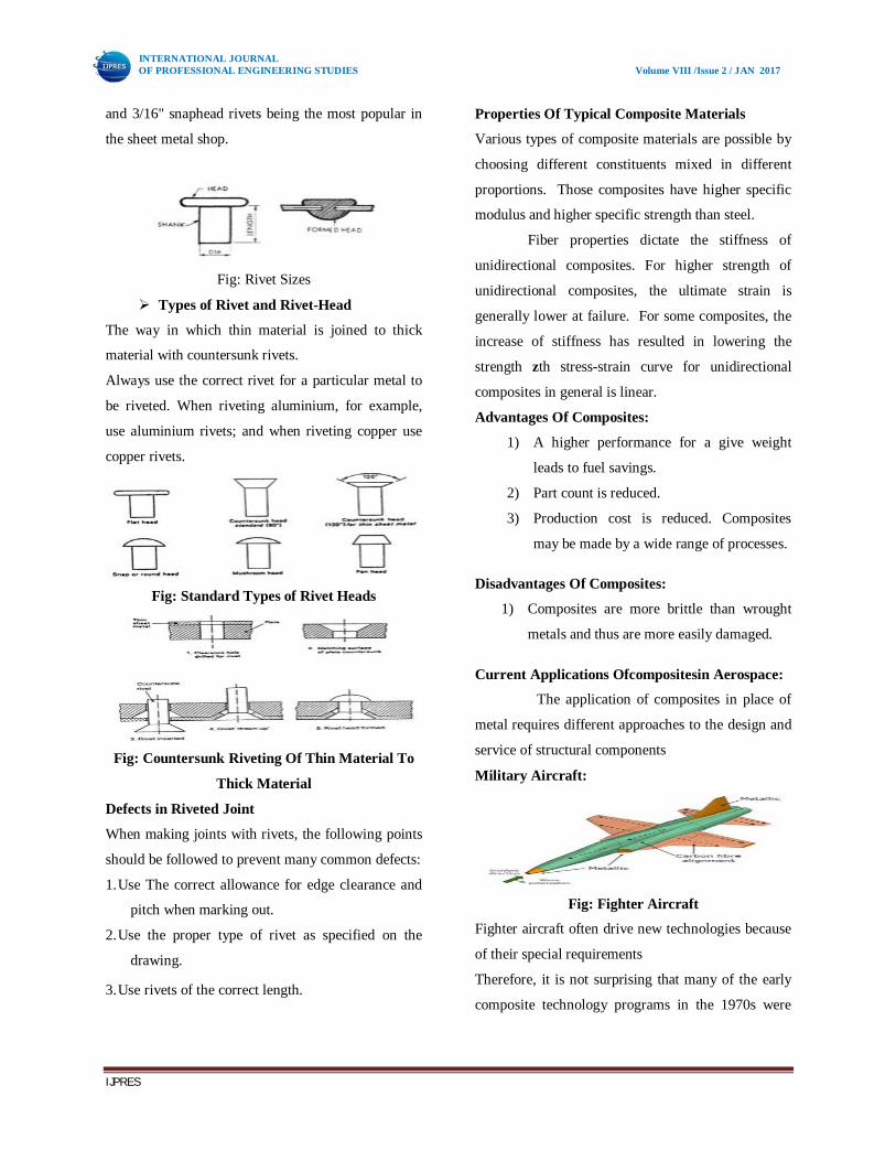
Military Aircraft:
Fig: Fighter Aircraft
Fighter aircraft often drive new technologies because
of their special requirements
Therefore, it is not surprising that many of the early
composite technology programs in the 1970s were

INTERNATIONAL JOURNAL OF PROFESSIONAL ENGINEERING STUDIES Volume VIII /Issue 2 / JAN 2017
IJPRES
part of fighter aircraft development projects such as
the F15, Alphajet,Tornado and Mirage.
Introduction to Project:
In materials science, fatigue is the progressive and
localized structural damage that occurs when a
material is subjected to cyclic loading. The nominal
maximum stress values are less than the ultimate
tensile stress limit, and may be below the yield stress
limit of the material.
Fatigue occurs when a material is subjected to
repeated loading and unloading. If the loads are
above a certain threshold, microscopic cracks will
begin to form at the stress concentrators such as the
surface, persistent slip bands (PSBs), and grain
interfaces. Eventually a crack will reach a critical
size, and the structure will suddenly fracture.
Fatigue failures often occur quite suddenly with
catastrophic (disastrous) results and although most
insidious for metals, polymers and ceramics (except
for glasses) are also susceptible to sudden fatigue
failures. Fatigue causes brittle like failures even in
normally ductile materials with little gross plastic
deformation occurring prior to fracture.
The simplest is completely reversed constant
amplitude where the alternating stress varies from a
maximum tensile stress to a minimum compressive
stress of equal magnitude.
Fig: Comparison of Metal and Composite
Stiffness Reduction
Importance of composites in Aero space
In the year 2005 a new damage accumulation model
for fatigue life prediction of composite laminates is
proposed has been studied. The model is constructed
on the ply level and uses a new multiaxial damage
index to consider the damage caused by different
stress components. The fatigue life is predicted based
on the proposed model and experimental results of
the unidirectional laminates. The numerical results
are compared with the experimental data for balanced
laminates.
Literature of composites in Aerospace
Composites are widely being used in many
applications like sporting goods, boating, building
construction, aviation industry etc, due to its high
strength and low weight advantages. Progressive loss
of stiffness during fatigue of a composite is a very
important characteristic.
Fig: Load curve for fatigue analysis
Fatigue Crack Propagation:
Crack growth rate da/dn is related to the cyclic stress
intensity factor range Δk, according to the power law
relationship formulated by paries and erdogan (1963).
da/dn = A (Δk)^m
The applied cyclic stress intensity range is given by:
Δk = YΔσ√πa
Y is a geometric factor, Δσ is the cyclic stress range,
and a is the crack length.
(S-N) Curve
S-NFrefers to a plot of Constant Amplitude Stress
Level (S) verses Number of Cycles to Failure (NF).
Fig: S-NF Curve
Introduction to Fatigue:
Fatigue, or metal fatigue, is the failure of a
component as a result of cyclic stress. The failure

INTERNATIONAL JOURNAL OF PROFESSIONAL ENGINEERING STUDIES Volume VIII /Issue 2 / JAN 2017
IJPRES
occurs in three phases: crack initiation, crack
propagation, and catastrophic overload failure.
Theoretical calculations:
Specimen’s diameter:
Sheet diameter = 1st raw material sheet length (l)
210+210=420
Sheet diameter= 2nd raw material sheet length (l)
210+150=360
Hole diameter =5 mm
Pitch diameter=12.
Width = 150
The mechanical properties =(0.2% yield stress =
291MPa,
Ultimate strength = 433 MPa,
Elongation = 13%
fatigue crack growth behavior of this material are
similar to those of the western Al 2024-T3 alloy
Force controlled riveting was applied using a
squeezer mounted in the grips of a MTS 810 fatigue
machine.The same machine was utilized in the
fatigue tests carried out under constant amplitude
loading at a stress ratio of 0.1.
Selecting the Correct Size of Rivet
To obtain the full strength of a riveted joint, a rivet of
the correct diameter and length must be used.
TD 25.1 (Urwin's formula);
Fatigue calculations
What is Finite Element Analysis?
FEA consists of a computer model of a material or
design that is stressed and analyzed for specific
results. It is used in new product design, and existing
product refinement.
Software’s used:
Solid-works: For CAD modeling of the lap jointed
fuselage skin and rivets
Hyper-mesh: For Meshing the model.
Radioss(solver): Radioss is used for solving the
structural analysis problems.
ANSYS Fatigue: Used for calculating the life span of
the fuselage skin under repeated loads.
Construction Of Fuselage Skin:
The fuselage skins are constructed by using lap joint
and by using nuts and bolts.In our case the fuselage
skin is joined together by using the lap joint.
Fig: Typical Fuselage Longitudinal Riveted Lap
Splice Joint
Figure: Geometry dimensions of the Fuselage
Geometry model:
Figure: Geometry of the fuselage skin with lap joint
Exploded view:
Figure: Exploded view of the geometry

INTERNATIONAL JOURNAL OF PROFESSIONAL ENGINEERING STUDIES Volume VIII /Issue 2 / JAN 2017
IJPRES
Meshing of the Geometrical model:
The fuselage skin is meshed by using the hyper-
mesh.Shell elements are used for fuselage skin and
beam elements are used for rivets modeling
Figure: Mesh model of the Fuselage skin
Modeling of rivets and rigid for coupling of rivets
and fuselage:
Figure: Mesh model with Bolts at hole locations
Figure: Exploded view of the bolt location
Enlarged view of the assembly showing rivets in pink
colour
Figure: Enlarged view of the Assembly
Material properties:
Table 1: Material properties
Load acting in our case:
Tensile load:
Figure: Load acting over the fuselage
Boundary conditions:
Figure: Constraint locations
Different load cases considering for analysis:
Loading Cases
Case 1: Material used as aluminum
Case 2: Composites (carbon fiber) with piles
orientation as(0/45/90/-45/0)
Case 3: Composites (carbon fiber) with piles
orientation as (0/90/0/90/0)
Case 4:Composites (carbon fiber) with piles
orientation as (0/45/90/-45/90/0/0)
Analysis results:
Case 1: Material–Aluminum
Displacement plot
Figure: Displacement contour plot

INTERNATIONAL JOURNAL OF PROFESSIONAL ENGINEERING STUDIES Volume VIII /Issue 2 / JAN 2017
IJPRES
Figure: Von Misses stress contour plot
Stress plot
Case 2
Ply Orientation of Carbon-Fiber (0/45/90/-45/0)
Displacement plot
Figure: Displacement contour plot
Stress plot
Figure: Von-Misses stress contour plot
Figure: Principal stress in Ply 1
Figure: Principal stresses in Ply 2
Figure: Principal stresses in ply 3
Figure: Principal stresses in ply 4
Figure: Principal stresses in ply
Table 2: Tabulated results for case 2
Case 3:
Ply Orientation of Carbon-Fiber(0/90/0/90/0)
Displacement plot
Figure: Displacement Contour plot

INTERNATIONAL JOURNAL OF PROFESSIONAL ENGINEERING STUDIES Volume VIII /Issue 2 / JAN 2017
IJPRES
Stress plot
Figure: Von-Misses stress contour plot
Figure: Principal stress in ply 1
Table 3: Tabulated results for case 3
Case 4
Ply Orientation of Carbon-Fiber (0/45/90/-
45/90/0/0)
Displacement plot
Figure: Displacement contour plot
Stress plot
Figure: Von Misses stress plot
Figure: Principal stress in ply 1
Table 4: Tabulated results for the case 4
Figure: S -N Curve for the Aluminium 2024
Figure: Unit Load acting for Fatigue analysis
Figure 1: Total life of the component
Figure: Logarithmic life of the component
By performing the fatigue analysis over the
composite fuselage structure the number of life
cycles it can with stand is 7e12
Results And Discussions
Tabulated results
From the table 5 we conclude that 2 different material
having different properties.

INTERNATIONAL JOURNAL OF PROFESSIONAL ENGINEERING STUDIES Volume VIII /Issue 2 / JAN 2017
IJPRES
Where aluminum has applications requiring high
strength to weight ratio, as well as good fatigue
resistance.Where carbon fiber has good mechanical
properties and having good fatigue resistance then
aluminum.From the above experiment we can
conclude that the case 4 with 7 plies has more
stiffness when compared to other so we replace the
aluminium with the Carbon Fiber containing 7 plies.
Conclusion
Carbon fiber composite is capable of withstanding
higher amount of load when compared to that of
aluminium 2024. The Application of aluminium in
the construction of aircraft fuselage can be replaced
by the carbon fibre effectively. The advantage of
replacing the aluminium 2024 by the carbon fibre is
not only it can withstand load in its operating
condition but also we will be reducing the weight of
the total fuselage skin by half. By using the carbon-
fiber the weight is reduced with indirectly increases
the fuel efficiency of the airplane.since now a day’s
composites are playing a main role in increasing the
overall efficiency of the commercial aircrafts by
reducing the weight and to withstanding enough
loads in its manuvering, takeoff and landing
operations, the usage of carbon fiber will be very
useful in the aerospace industry.
Future scope:
1. Increasing the efficiency of composite single-shear
lap joints.
2. CFRP with aluminum alloy plates can be tested in
experimental.
3. CFRP with aluminum alloy plates can be tested in
experimentaland can find the strength and stress
distribution with differentcomposite materials.
4. The joint design can be made and optimization of
riveted jointcan be performed.
5. Stress and Failure Analysis of Laminated
Composite PinnedJoints can be performed. Carbon
fiber airframes mean that aircraft can be very
different in shape such a design could significantly
improve a plane's lift-to-drag ratio - making it much
more aerodynamically efficient, and also reduce its
overall weight.
References
1. www.callister –materials-sicence-an.html
2.www. Kawaius.com/carbon-fiber-pdf
3.Muller,R.P.G.(1995) Phd thesis ,Delft University of
Technology ,Netherlands.
4.www. Fiber materialsinc.com/cc comp.html
AUTHORS:
1. MUTLOORI EZEKIEL
Pg Scholar,
Department of MECH,
Malla Reddy College Of Engineering And
Technology (Sponsored by C.M.R. Educational
society) Autonomous Institution – UGC, Govt. of
India, NAAC-A Grade, Accredited by AICTE-
NBA, Affiliated to JNTUH Hyderabad,
Maisammaguda, Dhulapally post, Secunderabad-
500100
2. D.V. SUBBARAO
Assistant Professor
Department of MECH,
Malla Reddy College Of Engineering And
Technology (Sponsored by C.M.R. Educational
society) Autonomous Institution – UGC, Govt. of
India, NAAC-A Grade, Accredited by AICTE-NBA,
Affiliated to JNTUH Hyderabad, Maisammaguda,
Dhulapally post, Secunderabad-500100