Embed Size (px)
Citation preview

8/13/2019 Finite Element Analysis of Castellated Steel - MR WAKCHAURE, A v SAGADE
http://slidepdf.com/reader/full/finite-element-analysis-of-castellated-steel-mr-wakchaure-a-v-sagade 1/8
ISSN: 2277-3754International Journal of Engineering and Innovative Technology (IJEIT)
ISO 9001:2008 Certified
Volume 2, Issue 1, July 2012
365
Abstract — Use of castellated beam for various structures
rapidl y gaining appeal. Th is is due to incr eased depth of section
without any additional weight, high strength to weight ratio,
their lower maintenance and painting cost. The principle
advantage of castell ated beam is increase in vert ical bending
stif fness, ease of service provision and attr active appearance.
However one consequence of presence of web openi ng i s the
development of various local eff ects. I n thi s paper steel I section
was selected, castell ated beams were fabr icated with i ncrease in
depth of web openi ngs. To analyze the behavior of castell ated
steel beams having an I -shaped cross-section, modeli ng is
conducted using finite element software package ANSYS14.
Anal ysis is carri ed out on beam with two point load and simply
supported support conditi on. The defl ection at centre of beam
and study of vari ous fail ure patterns are studied. The beams with
increase in depth are then compared with each other and with
parent section f or vari ous parameters and for servi ceabili ty
cri teria. F rom the fi ni te element analysis resul ts, it i s concluded
that, the Castellated steel beam behaves satisfactorily with
regards to serviceabili ty requir ements up to a max imum web
opening depth of 0.6h. Castell ated beams have proved to be
effi cient for moderately loaded longer spans where the design iscontrol led by defl ection .
I ndex Terms - Castellated Beam, Web Opening, Cellular
Beam, Virendeel Mechanism, Plastic Hinges.
I. INTRODUCTION
Engineers are constantly trying to improve the materials
and practices of design and construction. One such
improvement occurred in built-up structural members in the
mid-1930, an engineer working in Argentina, Geoffrey
Murray Boyd, is castellated beam. Castellated beams are
such structural members, which are made by flame cutting arolled beam along its centerline and then rejoining the two
halves by welding so that the overall beam depth is increased
by 50% for improved structural performance against
bending. Since Second World War many attempts have been
made by structural engineers to find new ways to decrease the
cost of steel structures. Due to limitations on minimum
allowable deflection, the high strength properties of
structural steel cannot always be utilized to best advantage.
As a result several new methods aimed at increasing stiffness
of steel member, without any increase in weight of steel
required. Castellated beam is one of the best solutions.
The responsibility of a Structural Engineer lies in not
merely designing the structure based on safety and
serviceability considerations but he also has to consider the
functional requirements based on the use to which the
structure is intended. While designing a power plant
structure or a multi-storied building, the traditional
structural steel framing consists of beams and girders with
solid webs. These hinder the provision of pipelines and air
conditioning ducts, electrical wiring required for satisfactory
functioning for which the structure is put up.
The re-routing of services (or increasing the floor height at
the design stage for accommodating them) leads to additional
cost and is generally unacceptable. The provision of beams
with web openings has become an acceptable engineering
practice, and eliminates the probability of a service engineer
cutting holes subsequently in inappropriate locations. Beams
with web openings can be competitive in such cases, even
though other alternatives to solid web beams such as stub
girders, trusses etc are available. This form of construction
maintains a smaller construction depth with placement of
services within the girder depth, at the most appropriate
locations. The introduction of an opening in the web of the
beam alters the stress distribution within the member and
also influences its collapse behavior.
Fig.1 Terminology
Web Post: The cross-section of the castellated beam where
the section is assumed to be a solid cross-section.
Throat Width: The length of the horizontal cut on the root
beam. The length of the portion of the web that is included
with the flanges.
Throat Depth: The height of the portion of the web that
connects to the flanges to form the tee section.
II. FORMULATION OF RESEARCH OBJECTIVESTo achieve economy, castellated beam fabricated from its
parent solid webbed „I‟ section should have maximum
possible depth. An available literature does not deal with the
Finite Element Analysis of Castellated Steel
BeamM.R.Wakchaure, A.V. Sagade

8/13/2019 Finite Element Analysis of Castellated Steel - MR WAKCHAURE, A v SAGADE
http://slidepdf.com/reader/full/finite-element-analysis-of-castellated-steel-mr-wakchaure-a-v-sagade 2/8

8/13/2019 Finite Element Analysis of Castellated Steel - MR WAKCHAURE, A v SAGADE
http://slidepdf.com/reader/full/finite-element-analysis-of-castellated-steel-mr-wakchaure-a-v-sagade 3/8

8/13/2019 Finite Element Analysis of Castellated Steel - MR WAKCHAURE, A v SAGADE
http://slidepdf.com/reader/full/finite-element-analysis-of-castellated-steel-mr-wakchaure-a-v-sagade 4/8
ISSN: 2277-3754International Journal of Engineering and Innovative Technology (IJEIT)
ISO 9001:2008 Certified
Volume 2, Issue 1, July 2012
368
Fig.6 Position Of force application for Ic 210
Fig.7 Total Deflection of ISMB 150
Fig.8 Total Deflection of Ic 210 mm
Fig.9 Total Deflection of Ic 225 mm
Fig. 10 Total deflection for Ic 240
Fig.11 Maximum Stress of ISMB 150mm

8/13/2019 Finite Element Analysis of Castellated Steel - MR WAKCHAURE, A v SAGADE
http://slidepdf.com/reader/full/finite-element-analysis-of-castellated-steel-mr-wakchaure-a-v-sagade 5/8
ISSN: 2277-3754International Journal of Engineering and Innovative Technology (IJEIT)
ISO 9001:2008 Certified
Volume 2, Issue 1, July 2012
369
Fig.12 Maximum Stress of Ic 210mm
Fig.13 Maximum Stress of Ic 225mm
Fig.14 Maximum Stress of Ic 240mm
IV. R ESULTS OF ANSYS ANALYSIS
All Tables are shown in Appendix.
Graph.1Load v/s Deflection ISMB150
Graph.2 Load v/s Deflection for Ic210
Graph.3 Load v/s Deflection for Ic225
8/13/2019 Finite Element Analysis of Castellated Steel - MR WAKCHAURE, A v SAGADE
http://slidepdf.com/reader/full/finite-element-analysis-of-castellated-steel-mr-wakchaure-a-v-sagade 6/8
ISSN: 2277-3754International Journal of Engineering and Innovative Technology (IJEIT)
ISO 9001:2008 Certified
Volume 2, Issue 1, July 2012
370
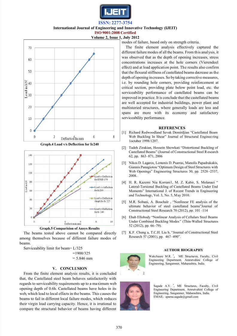
Graph.4 Load v/s Deflection for Ic240
Graph.5 Comparision of Ansys Results
The beams tested above cannot be compared directly
among themselves because of different failure modes of
beams.
Serviceability limit for beam= L/325
=1900/325
= 5.846 mm
V. CONCLUSION
From the finite element analysis results, it is concluded
that, the Castellated steel beam behaves satisfactorily with
regards to serviceability requirements up to a maximum web
opening depth of 0.6h. Castellated beams have holes in its
web, which lead to local effects in the beams. This causes the beams to fail in different local failure modes, which reduces
their virgin load carrying capacity. Hence, it is irrational to
compare the structural behavior of beams having different
modes of failure, based only on strength criteria.
The finite element analysis effectively captured the
different failure modes of all the beams. From this analysis, it
was observed that as the depth of opening increases, stressconcentrations increases at the hole corners (Vierendeel
effect) and at load application point. The results also confirm
that the flexural stiffness of castellated beams decrease as the
depth of opening increases. So by taking corrective measures,
i.e. by rounding hole corners, providing reinforcement at
critical section, providing plate below point load, etc. the
serviceability performance of castellated beams can be
improved in practice. It is conclude that the castellated beams
are well accepted for industrial buildings, power plant and
multistoried structures, where generally loads are less and
spans are more with its economy and satisfactory
serviceability performance.
REFERENCES[1] Richard Redwoodland Sevak Demirdjian “Castellated Beam
Web Buckling In Shear” Journal of Structural Engineering
1october 1998/1207.
[2] Tadeh Zirakian, Hossein Showkati “Distortional Buckling of
Castellated Beams” (Journal of Constructional Steel R esearch
62, pp. 863 – 871, 2006
[3] Nikos D. Lagaros, Lemonis D. Psarras, Manolis Papadrakakis,
Giannis Panagiotou “Optimum Design of Steel Structures with
Web Openings” Engineering Structures 30, pp. 2528 – 2537,
2008.
[4] H. R. Kazemi Nia Korrani1, M. Z. Kabir, S. Molanaei “
Lateral-Torsional Buckling of Castellated Beams Under End
Moments” International J. of R ecent Trends in Engineering
and Technology, Vol. 3, No. 5, May 2010.
[5] M.R. Soltani, A. Bouchaïr , “Nonlinear FE analysis of the
ultimate behavior of steel castellated beams”Journal of
Constructional Steel Research 70 (2012), pp. 101 – 114
[6] Ehab Ellobody “Nonlinear Analysis of Cellulars Steel Beams
Under Combined Buckling Modes” (Thin-Walled Structures
52 (2012), pp. 66 – 79).
[7] K.F. Chung a, T.C.H. Liu b, “Journal of Constructional Steel
Research 57 (2001), pp. 467 – 490”.
AUTHOR BIOGRAPHY
Wakchaure M.R. *, ME Structures, Faculty, Civil
Engineering Department, Amrutvahini College of
Engineering, Sangamner, Maharashtra, India.
Sagade A.V. *, ME Structures, Faculty, Civil
Engineering Department, Amrutvahini College of
Engineering, Sangamner, Maharashtra, India.EMAIL: [email protected]

8/13/2019 Finite Element Analysis of Castellated Steel - MR WAKCHAURE, A v SAGADE
http://slidepdf.com/reader/full/finite-element-analysis-of-castellated-steel-mr-wakchaure-a-v-sagade 7/8
ISSN: 2277-3754International Journal of Engineering and Innovative Technology (IJEIT)
ISO 9001:2008 Certified
Volume 2, Issue 1, July 2012
371
Appendix
Table I. Load and Deflections of ISMB 150
&Table II.Load and Deflections of Ic=210
Table.III Load Vs Deflection for Ic 225
&
Table.IV Load v/s Deflection for Ic 240
Sr. No. Load ( kN) Deflection (mm)
1 0 0
2 10 0.43572
3 20 0.87945
4 30 1.3412
5 40 1.7549
6 50 2.1888
7 60 2.5782
8 70 3.0065
9 80 3.4618
10 90 3.8235
11 100 4.2372
12 110 4.651
13 120 5.0647
Sr. No. Load ( kN) Deflection (mm)
1 0 0
2 10 0.6648
320 1.3338
430 2.0085
540 2.6839
650 3.3652
760 4.0506
870 4.7402
980 5.4341
10 90 6.1325
11100 6.8345
12110 7.5412
13120 8.2522
Sr.No. Load ( kN) Deflection (mm)
1 0 0
2 10 0.8099
3 20 1.6199
4 30 2.4298
5 40 3.23976 50 4.0497
7 60 4.8596
8 70 5.6695
9 80 6.4795
10 90 7.2894
11 100 8.0993
12 110 8.8534
13 115 9.3143
Sr. No. Load ( kN) Deflection (mm)
1 0 0
2 10 0.8934
3 20 1.8018
4 30 2.7130
5 40 3.6347
6 50 4.5686
7 60 5.5123
8 65 5.9880

8/13/2019 Finite Element Analysis of Castellated Steel - MR WAKCHAURE, A v SAGADE
http://slidepdf.com/reader/full/finite-element-analysis-of-castellated-steel-mr-wakchaure-a-v-sagade 8/8
ISSN: 2277-3754International Journal of Engineering and Innovative Technology (IJEIT)
ISO 9001:2008 Certified
Volume 2, Issue 1, July 2012
372
Table V. Comparison of ANSYS Results for Serviceability Limit
Sr. No. Beam Deflection
(mm)
Load by
ANSYS
(kN)
Local Mode Of Failure Global Mode of failure
1 ISMB
150
5.84
135 Failure of compression flange Lateral Torsional buckling
2 Ic 210 85 Failure of compression flange Flexural buckling of Web
3 Ic 225 70 Failure of compression flange and
Vierendeel effect
Web buckling
4 Ic 240 65 Vierendeel effect and Failure of
compression flange
Flexural buckling of Web


![Numerical analysis of castellated beams with oval openings · of castellated beams with various openings, i.e., square, hexagonal, and circular. Wakchaure and Sagade [5] undertook](https://img.pdfslide.us/doc/110x75/6065a854826ddc2c1d7fe375/numerical-analysis-of-castellated-beams-with-oval-openings-of-castellated-beams.jpg)