Embed Size (px)
Citation preview

International Research Journal of Engineering and Technology (IRJET) e-ISSN: 2395 -0056
Volume: 03 Issue: 04 | April-2016 www.irjet.net p-ISSN: 2395-0072
© 2016, IRJET | Impact Factor value: 4.45 | ISO 9001:2008 Certified Journal | Page 2605
Finite Element Analysis of a Portal Axle Gear Train using
Metallic and Composite Spur Gears
Umesh Shinde1, Deepak C Patil2
1Dept of Mechanical Engineering, KLE Dr.MSSCET Belagavi, Karnataka, India 2Professor, Dept of Mechanical Engineering, KLE Dr.MSSCET Belagavi, Karnataka, India
---------------------------------------------------------------------***---------------------------------------------------------------------
Abstract - The portal axle is generally a gearbox that is designed for off road driving conditions. It is installed between the wheel and the axle shaft to give higher ground clearance to the vehicle. The modeling and simulation of spur gears in portal axle is important to predict the actual motion behavior. In this study, static analysis of portal axle is simulated using finite element method (FEM) for both metallic and composite gears. The three gear trains being analyzed are gear train without idler gear, one idler gear and two idler gears. FEM static stress analysis is also simulated on three different gear trains to study the gear teeth bending stress and contact stress behavior of the gear trains. This methodology serves as a novel approach for gear train design evaluation, and the study of gear stress behavior in gear train which is needed in the small workshop scale industries.
Key Words: Portal axle, Spur gears, Stress analysis, Gear train, Metallic and Composite Gears.
1.INTRODUCTION
Fig 1: Normal and Portal Axle
The portal axle is a gearbox unit with at least two gears (input and output gear) combined to give greater off-set between the input gear and output gear. Portal axles are commonly installed on four wheel-drive (4WD) vehicles for driving on off-road conditions and to gain additional ground clearance to protect underneath components from damage. Fig. 1 shows the comparison between a normal vehicle and a vehicle with a portal axle.
The modeling and simulation of such all-terrain vehicles are important to predict the actual motion behavior.
When designing gears for portal axle, consideration of the gear train dynamic response is critical. In this situation, the structural stress level may become very high and generate structural deficiencies. The present work is carried taking metallic and composite gears. For metallic cast steel is considered and for composite carbon fiber epoxy is taken for the analysis purpose. Positioning of each gear in a gear train to the desired position for FEM simulation requires accurate contact settings, constraints and positioning technique. The critical stress calculated using FEM is recorded at the input gear shaft and output gear shaft and simulated for three different gear trains. Finally, discussions and conclusions are pointed out from the analysis of this work.
2. MODEL OF GEAR SHAFT AND IDLER GEAR
Fig. 2. Gear shafts assembly of the portal axle unit
Fig. 2 shows the assembly model of the three-gear system of the portal axle unit. In this analysis, the model of the input gear shaft, output gear shaft, and idler gear is only considered in FEM analysis to save computing time. This ignores the interaction of the housing fitting and the bearings fitting of the portal axle. The output shaft and input shaft of the portal axle are modeled as the same gear shaft which shares the same design parameters. The gear shaft is modeled using the Solid Works 2014. The length of the shaft is 200 mm and the diameter is 30 mm. The idler gear, which is meshed between the input gear and output gear, is model with the same shaft diameter and having a shorter length of 100 mm. The idler gear is positioned between the input gear and output gear to offset the vertical distance and allow only one directional rotation.

International Research Journal of Engineering and Technology (IRJET) e-ISSN: 2395 -0056
Volume: 03 Issue: 04 | April-2016 www.irjet.net p-ISSN: 2395-0072
© 2016, IRJET | Impact Factor value: 4.45 | ISO 9001:2008 Certified Journal | Page 2606
All gears (gear shaft and idler gear) are modeled following the same gear design parameters and material properties for both metallic and composite gears as shown in Table 2.3 and Table 2.4. The effects of gear case hardening, gear tempering and other gear heat treatment process are not considered in this study. Therefore, only the material of the gear is taken account into the analysis in FEM.
Table 2.1: Gear Shaft Parameters
Gear type Standard involute, full depth teeth
Number of teeth (N) 20
Pitch diameter (d) 80 mm
Module (M) 4.00 mm
Diametral pitch ( pd ) 250 mm-1
Pressure angle ( ) 20°
Addendum (mm) 1.0 M
Dedendum (mm) 1.25 M
Face width (bw) 40 mm
2.1 Model of the three different Gear Trains
Table 2.2: Three different gear train
There are three different gear train designs
considered in the interest of this research, and three different gear trains are assembled as shown in Table 2.2 so that FEM simulation can be carried out separately. A gear train with no idler gear which is made up of two identical gear shafts is constrained to mesh with one and another. The gear shafts are set at center distance 80 mm and are aligned vertically with reference to both the gear shaft axis.
A gear train with one idler gear is built up of two gear shafts and one idler gear. The idler gear is the
intermediate gear which connects between the two gear shafts. The center distance between the input gear and idler gear is 80 mm and the input gear is aligned to 45º from horizontal to mesh with the idler gear. Similarly, the center distance between the output gear and idler gear is 80 mm and the output gear is aligned 120 45º from horizontal downwards. A gear train with two idler gears is arranged in the same position compared to the gear train with one idler gear but with one idler gear attached on the other side between the input gear and output gear. All gear components in gear trains are constrained to rotate based on a gear ratio of 1:1 for FE analysis in the later sections.
2.2 Material Selection
2.2.1 Metallic Gear: Cast Steel
Cast steel was the first type of steel that allowed alloys to be added to the iron. Prior to this method, manufacturers had not been able to get steel hot enough to melt. By heating blister steel in a clay crucible placed directly into a fire, Huntsman allowed the metal to reach up to 2900°F (1600°C). Melting allowed other elements, such as nickel, to be mixed into the metal, thus strengthening the steel.
Cast steel has a rough finish. It often has surface holes created by gas bubbling during the heating process. An elastic metal, this type of steel is very tough, having four times the tensile strength of cast iron. Tensile strength is how much pressure, created by pulling, an object can withstand before it breaks.
Table 2.3: Properties of Cast Steel
Cast Steel
Density 7870 kg/m3
Young modulus 200 GPa
Poisson’s ratio 0.29
Tensile strength 518.8 MPa
Ultimate Tensile Strength
540 MPa
Yield Tensile Strength
415 MPa
2.2.2 Composite Gear: 50% Carbon Fibers and Epoxy Resin Matrix
A composite material can be defined as a combination of two or more materials that results in better properties than those of the individual components used alone. In contrast to metallic alloys, each material retains its separate chemical, physical, and mechanical properties. The two constituents are reinforcement and a matrix. The main advantages of composite materials are their high strength and stiffness, combined with low density, when compared
International Research Journal of Engineering and Technology (IRJET) e-ISSN: 2395 -0056
Volume: 03 Issue: 04 | April-2016 www.irjet.net p-ISSN: 2395-0072
© 2016, IRJET | Impact Factor value: 4.45 | ISO 9001:2008 Certified Journal | Page 2607
with bulk materials, allowing for a weight reduction in the finished part. The reinforcing phase provides the strength and stiffness. In most cases, the reinforcement is harder, stronger, and stiffer than the matrix. The reinforcement is usually a fiber or a particulate. Particulate composites have dimensions that are approximately equal in all directions.
Carbon fibers are available from a number of domestic and foreign manufacturers in a wide range of forms having an even wider range of mechanical properties. The earliest commercially available carbon fibers were produced by thermal decomposition of rayon precursor materials.
Epoxy resins are widely used in filament-wound composites and are suitable for molding prepress. They are reasonably stable to chemical attacks and are excellent adherent shaving slow shrinkage during curing and no emission of volatile gases. These advantages, however, make the use of epoxies rather expensive. Also, they cannot be expected beyond a temperature of 140ºC. Their use in high technology areas where service temperatures are higher, as a result, is ruled out. Epoxy-reinforced concrete and glass-reinforced and carbon-reinforced epoxy structures are used in building and bridge structures.
Table 2.4: Properties of Composite Gear
Composite Gear: 50% Carbon Fibers and Epoxy Resin Matrix
Density 1800 kg/
Young modulus 450 GPa
Poisson’s ratio 0.30
Tensile strength 52 MPa
Compressive strength 600 MPa
3. Static Stress Analysis
Static stress analysis using FEM was performed on the three types of gear train, focusing mainly on the gear tooth bending stress and contact stress caused by two contacting gear teeth. FEM stress analysis was simulated on gear trains with different combinations (without idler, one idler and two idler gears). The three types of gear train bending stress and contact stress behavior are analyzed separately with respect to metallic and composite gear.
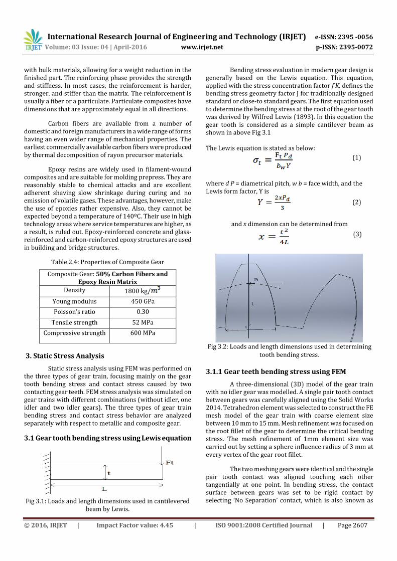
3.1 Gear tooth bending stress using Lewis equation
Fig 3.1: Loads and length dimensions used in cantilevered
beam by Lewis.
Bending stress evaluation in modern gear design is generally based on the Lewis equation. This equation, applied with the stress concentration factor f K, defines the bending stress geometry factor J for traditionally designed standard or close-to standard gears. The first equation used to determine the bending stress at the root of the gear tooth was derived by Wilfred Lewis (1893). In this equation the gear tooth is considered as a simple cantilever beam as shown in above Fig 3.1
The Lewis equation is stated as below:
(1)
where d P = diametrical pitch, w b = face width, and the Lewis form factor, Y is
(2)
and x dimension can be determined from
(3)
Fig 3.2: Loads and length dimensions used in determining
tooth bending stress.
3.1.1 Gear teeth bending stress using FEM
A three-dimensional (3D) model of the gear train with no idler gear was modelled. A single pair tooth contact between gears was carefully aligned using the Solid Works 2014. Tetrahedron element was selected to construct the FE mesh model of the gear train with coarse element size between 10 mm to 15 mm. Mesh refinement was focused on the root fillet of the gear to determine the critical bending stress. The mesh refinement of 1mm element size was carried out by setting a sphere influence radius of 3 mm at every vertex of the gear root fillet.
The two meshing gears were identical and the single pair tooth contact was aligned touching each other tangentially at one point. In bending stress, the contact surface between gears was set to be rigid contact by selecting ‘No Separation’ contact, which is also known as
International Research Journal of Engineering and Technology (IRJET) e-ISSN: 2395 -0056
Volume: 03 Issue: 04 | April-2016 www.irjet.net p-ISSN: 2395-0072
© 2016, IRJET | Impact Factor value: 4.45 | ISO 9001:2008 Certified Journal | Page 2608
linear contact. Frictional or nonlinear contact was ignored in this analysis to reduce computing time.
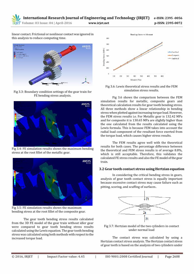
Fig 3.3: Boundary condition settings of the gear train for FE bending stress analysis.
Fig 3.4: FE simulation results shows the maximum bending stress at the root fillet of the metallic gear.
Fig 3.5: FE simulation results shows the maximum bending stress at the root fillet of the composite gear.
The gear tooth bending stress results calculated from the 3D FE model of the gear train without idler gear were compared to gear tooth bending stress results calculated using the Lewis equation. The gear tooth bending stress was calculated using both methods with respect to the increased torque load.
Fig 3.6: Lewis theoretical stress results and the FEM simulation stress results.
Fig 3.6 shows the comparison between the FEM simulation results for metallic, composite gears and theoretical calculation results for gear tooth bending stress. All three methods show a linear relationship in bending stress when plotted against increasing torque load. However, the FEM stress results i.e. For Metallic gear is 132.42 MPa and for composite it is 130.65 MPa are slightly higher than the one calculated from the results calculated using the Lewis formula. This is because FEM takes into account the radial load component of the resultant force exerted from the torque load, which causes higher stress results.
The FEM results agree well with the theoretical results for both cases. The percentage difference between the theoretical and FEM stress results is of average 8.8%, which is still acceptable. Therefore, this validates the calculated FE stress results and also the FE model of the gear train.
3.2 Gear tooth contact stress using Hertzian equation
In considering the critical bending stress in gears, analysis of gear tooth contact stress is equally important because excessive contact stress may cause failure such as
pitting, scoring, and scuffing of surfaces.
Fig 3.7: Hertzian model of the two cylinders in contact under normal load
The contact stress was calculated by using a
Hertzian contact stress analysis. The Hertzian contact stress of gear teeth is based on the analysis of two cylinders under

International Research Journal of Engineering and Technology (IRJET) e-ISSN: 2395 -0056
Volume: 03 Issue: 04 | April-2016 www.irjet.net p-ISSN: 2395-0072
© 2016, IRJET | Impact Factor value: 4.45 | ISO 9001:2008 Certified Journal | Page 2609
a radial load. It is assumed in the gear model that the radii of cylinders are the radii of curvature of the involute tooth forms of the mating teeth at the band of contact. The band of contact between the two cylinders can be calculated as 2a where the deformed distance, a is equal to
(4)
The Hertzian theory assumes an elliptic stress distribution, as seen in the Fig.; the maximum stress is in the middle and equals to
(5)
where W is the normal load, 1 E and 2 E are the modulus of
elasticity of the pinion and gear, respectively, and are
Poisson’s ratios of the pinion and gear, respectively, and
is the face width of pinion. and are the respective radii
of the involute curve at the contact point, as shown in Fig.
However, the pitch radius of the pinion and gear
denoted as and , respectively, can be related to the
gear involute radii as and .
Hence, the Hertzian equation for contact stresses in the teeth becomes (6)
In the Hertz contact stress equation, a few assumptions are made, such as pure bending of short beam, elliptic distribution of stresses at tooth contact, and friction between the gear contacting surfaces is not accounted in the stress equation. A question therefore arises concerning their accuracy. The elastic compression of two-dimensional bodies in contact cannot be calculated solely from the contact stresses given by the Hertzian theory.
Fig 3.8: Two involute teeth in contact
3.2.1 Gear tooth contact stress using FEM
The 3D FE gear train with no idler gear is imported into the ANSYS Workbench. FEM settings of gear train without idler gear FE model are described in this section for close comparison with the Hertzian contact model, which describes on two identical and symmetrical cylindrical contacts. Single pair tooth contact between gears was carefully aligned using the Solid Works program. For contact stress analysis between two interacting gear teeth, non-linear contact or also known as frictional contact was assigned. The coefficient of friction of the contacting gear tooth surface was set to 0.2.
The load and constraints were set similar to the one set for FEM bending analysis as shown in Fig 3.3. The cylindrical support, which only allows free rotation, represents the virtual bearings to support the gear. Moment of 200 Nm was applied at the shaft of the input gear and the shaft of the output gear is fully constrained.
Fig 3.9: FEM stress distribution of the two contacting gear
teeth in side view for metallic gear.
Fig 3.10: FEM stress distribution of the two contacting gear teeth in side view for composite gear.
Fig 3.8 and Fig 3.9 shows the stress distribution of the two contacting gears in side view when subjected to 200 Nm torque. The maximum stress of 685.66 MPa for metallic gear and 680.85 MPa for composite gear occurs at the gear teeth surface of the gear. From the side view, the contact stress distribution between the two gears is not precise because the contacting nodes are not arranged in a similar pattern. The nodes built from the element of both gear teeth

International Research Journal of Engineering and Technology (IRJET) e-ISSN: 2395 -0056
Volume: 03 Issue: 04 | April-2016 www.irjet.net p-ISSN: 2395-0072
© 2016, IRJET | Impact Factor value: 4.45 | ISO 9001:2008 Certified Journal | Page 2610
must coincide to form a much precise solution to contact stress.
A more detailed contact stress distribution on the gear tooth surface of the input gear can be seen in Fig. after putting input gear model to hidden. It is expected that a long stretch of high stress band contact should be formed along the gear tooth surface. However, this is not the case due to uneven node formation along the gear tooth surface.
Fig 3.11: Hertzian theoretical stress results and the FEM
simulation stress results.
The percentage difference between the theoretical and FEM stress results is on average 7.3%. There is a difference in the results calculated between both methods because the Hertz equation does not consider the tangential force, which contributes to frictional force on the gear tooth surface. FEM results agree well with the theoretical results for both cases. The slight difference between the two methods is acceptable, which validates the calculated FE contact stress results and the FE model of the gear train.
4. Conclusion
The gear tooth bending stress and contact stress were validated by comparing the FEM stress results with the results calculated from Lewis theory and Hertz theory. Both Lewis stress and contact stress have good agreement with difference of 8.8% to 7.3% on average. In bending stress analysis, the gear train without an idler gear has the highest stress among the other two. Besides, the input gear has overall higher root bending stress compared to the root bending stress at the output gear.
The study in weight reduction and stress distribution of spur gear for cast steel and composite materials has been done. On the basis of that study, the analysis of both cast steel and composite materials are analyzed in the application of gear box which is used in automobile portal vehicles in which weight reduction was found by reduction of 77%. From these analysis we got the stress values for composite materials is less as compared to the cast steel spur gear. So from these analysis results, we conclude that, the stress induced is less as compared to the
cast steel spur gear. So, Composite materials are capable of using in automobile vehicle gear boxes.
REFERENCES
[1] Bhandari V B 2010, Design of Machine Elements, Tata McGraw Hill, New Delhi.
[2] S. S. Rao, 2011, The Finite Element Method in Engineering.
[3] Tawanda Mushiri, Charles M bohwa, “Analysis of a gear train using finite element modelling” International Conference on Operations Excellence and Service Engineering Orlando, Florida, USA, September 10-11, 2015.
[4] S. Mahendran, K.M. Eazhil, “Design and Analysis of Composite Spur Gear” International Journal of Research and Scientific Innovation, Volume I, Issue VI, November 2014.
[5] V. Siva Prasad, Syed Altaf Hussain, V. Pandurangadu, K. Palani Kumar, “Modeling and Analysis of Spur Gear for Sugarcane Juice Machine under Static Load Condition by Using FEA”, International Journal of Modern Engineering Research (IJMER), Vol.2, Issue.4, July-Aug 2012 pp-2862-2866, ISSN: 2249- 6645.
[6] Utkarsh. M. Desai, Dhaval. A. Patel, “Modeling And Stress Analysis Of Composite Material For Spur Gear Under Static Loading Condition” Technical Research Organisation India.
[7] Mahebub Vohra, 2 Prof. Kevin Vyas, “Comparative Finite Element Analysis of Metallic and Non Metallic Spur Gear” IOSR Journal of Mechanical and Civil Engineering (IOSR-JMCE), Volume 11, Issue 3 Ver. IV (May- Jun. 2014), PP 136-145.
[8] Sanjay K. Khavdu1, Prof. Kevin M. Vyas2, “Finite Element Analysis of Lathe Machine Tumbler Gear Mechanism” International Journal of Research in Aeronautical And Mechanical engineering, Vol.3 Issue.4, April 2015. Pgs.: 36-44.