Embed Size (px)
Citation preview

This article was downloaded by: [University of Connecticut]On: 11 October 2014, At: 14:33Publisher: Taylor & FrancisInforma Ltd Registered in England and Wales Registered Number: 1072954 Registered office: Mortimer House,37-41 Mortimer Street, London W1T 3JH, UK
International Journal of Computational Fluid DynamicsPublication details, including instructions for authors and subscription information:http://www.tandfonline.com/loi/gcfd20
Finite difference gas-kinetic BGK scheme forcompressible inviscid flow computationAshraf A. Omar a , Ong J. Chit b , Lim J. Hsuh b & Waqar Asrar aa Department of Mechanical Engineering , Faculty of Engineering, International IslamicUniversity Malaysia , P. O. Box 10, 50728, Kuala Lumpur, Malaysiab Faculty of Mechanical Engineering, University Technology MARA Pulau Pinang , 13500,Permatang Pauh, Penang, MalaysiaPublished online: 24 Apr 2008.
To cite this article: Ashraf A. Omar , Ong J. Chit , Lim J. Hsuh & Waqar Asrar (2008) Finite difference gas-kinetic BGK schemefor compressible inviscid flow computation, International Journal of Computational Fluid Dynamics, 22:3, 183-192, DOI:10.1080/10618560701812824
To link to this article: http://dx.doi.org/10.1080/10618560701812824
PLEASE SCROLL DOWN FOR ARTICLE
Taylor & Francis makes every effort to ensure the accuracy of all the information (the “Content”) containedin the publications on our platform. However, Taylor & Francis, our agents, and our licensors make norepresentations or warranties whatsoever as to the accuracy, completeness, or suitability for any purpose of theContent. Any opinions and views expressed in this publication are the opinions and views of the authors, andare not the views of or endorsed by Taylor & Francis. The accuracy of the Content should not be relied upon andshould be independently verified with primary sources of information. Taylor and Francis shall not be liable forany losses, actions, claims, proceedings, demands, costs, expenses, damages, and other liabilities whatsoeveror howsoever caused arising directly or indirectly in connection with, in relation to or arising out of the use ofthe Content.
This article may be used for research, teaching, and private study purposes. Any substantial or systematicreproduction, redistribution, reselling, loan, sub-licensing, systematic supply, or distribution in anyform to anyone is expressly forbidden. Terms & Conditions of access and use can be found at http://www.tandfonline.com/page/terms-and-conditions

Finite difference gas-kinetic BGK scheme for compressible inviscid flow computation
Ashraf A. Omara*, Ong J. Chitb, Lim J. Hsuhb and Waqar Asrara
aDepartment of Mechanical Engineering, Faculty of Engineering, International Islamic University Malaysia, P. O. Box 10, 50728
Kuala Lumpur, Malaysia; bFaculty of Mechanical Engineering, University Technology MARA Pulau Pinang, 13500 Permatang Pauh,
Penang, Malaysia
(Received 5 July 2007; final version received 27 October 2007 )
In this paper, the gas-kinetic Bhatnagar–Gross–Krook (BGK) scheme is developed using the finite difference method
and applied to simulate 2D compressible inviscid flow. The numerical scheme employed in this study, namely the BGK
scheme, is based on the collisional Boltzmann model. The high-order resolution of this scheme is obtained by utilising
the monotone upstream-centred schemes for conservation law-type primitive variable reconstruction. As for the time
integration part of the scheme, a multistage Runge–Kutta method is employed. In order to assess the computational
characteristics of the numerical scheme, namely accuracy and robustness, three flow problems are selected in this study.
They are supersonic channel flow, supersonic wedge cascade and circular arc bump. The computed results of these test
cases are validated with available exact solutions and numerical results from the central difference scheme with total
variation diminishing (TVD) formulation. It shows that the BGK scheme is an accurate and robust scheme in comparison
to the central difference scheme with TVD when used to simulate 2D compressible inviscid flows.
Keywords: gas-kinetic BGK scheme; compressible inviscid flow; Boltzmann model; MUSCL; multistage
Runge–Kutta method
1. Introduction
Throughout the history of computational fluid dynamics
development, many numerical schemes have been created
to solve practical application of gas dynamics problems.
The key design criterion of any numerical schemes is to
maximise robustness and accuracy. This requirement is
particularly important in compressible flow solutions
involving high-speed flow where intense shock waves and
boundary layers may simultaneously exist. Among those
notable and successful are the Godunov-type and flux
vector splitting schemes. Besides these numerical
schemes that stem from the discretisation of the Euler
equations, the gas-kinetic schemes have attracted much
attention in recent years due to their high robustness and
accuracy in solving compressible flow problems.
Recent developments have seen the emergence of
another class of scheme known as the gas-kinetic schemes
that are developed based on the Boltzmann equation (Xu
1998a, Ong 2004). Mainly, there are two groups of gas-
kinetic schemes and the difference lies within the type of
Boltzmann equation used in the gas evolution stage. One
of them is the well-known kinetic flux vector splitting
(KFVS) scheme which is based on the collisionless
Boltzmann equation and the other is based on the
collisional Bhatnagar–Gross–Krook (BGK) model (Ong
et al. 2004a) where the BGK scheme is derived. Like any
other flux-vector-splitting (FVS) method, the KFVS
scheme is very diffusive and less accurate in comparison
with the Roe-type flux-difference-splitting (FDS)method.
The diffusivity of the FVS schemes is mainly due to the
particle or wave-free transport mechanism, which sets the
Courant-Friedrichs-Lewy (CFL) time step equal to
particle collision time (Xu 1998b). In order to reduce
diffusivity, particle collisions have to be modelled and
implemented into the gas evolution stage. One of the
distinct approaches to take particle collision into
consideration in gas evolution can be found in Xu
(1998a). In this method, the collision effect is considered
by the BGK model as an approximation of the collision
integral in theBoltzmannequation. It is found that this gas-
kinetic BGK scheme possesses accuracy that is superior to
the flux vector splitting schemes and avoids the anomalies
of FDS-type schemes (Chae et al. 2000, Ong et al. 2003,
Ong et al. 2004b, Abdusslam et al. 2006, Ong et al. 2006).
2. Numerical methods
The 2D normalised compressible Euler equations can be
written in the strong conservation form as
›W
›tþ
›F
›xþ
›G
›y¼ 0; ð1Þ
ISSN 1061-8562 print/ISSN 1029-0257 online
q 2008 Taylor & Francis
DOI: 10.1080/10618560701812824
http://www.informaworld.com
*Corresponding author. Email: [email protected]
International Journal of Computational Fluid Dynamics
Vol. 22, No. 3, March 2008, 183–192
Dow
nloa
ded
by [
Uni
vers
ity o
f C
onne
ctic
ut]
at 1
4:33
11
Oct
ober
201
4

where
W ¼
r
rU
rV
r1
26666664
37777775; F ¼
rU
rU 2 þ p
rUV
ðr1þ pÞU
26666664
37777775;
G ¼
rV
rUV
rV 2 þ p
ðr1þ pÞV
26666664
37777775;
where r, U, V, p and 1 are the macroscopic density,
x-component of velocity, the y-component of velocity,
the pressure and total energy, respectively. Subsequently,
Equation (1) is transformed into curvilinear coordinates
(j, h). Hoffmann and Chiang (1993) provide a detailed
description about this matter.
A standard BGK scheme is based on the collisional
Boltzmann equation and it is written in two dimensions
as (Xu 1998a)
›f
›tþ u
›f
›xþ v
›f
›y¼
ðg2 f Þ
t; ð2Þ
where f is the real particle distribution function and g is the
equilibrium state approached by f within a collision time
scale t. Both f and g are functions of space x, y; time t;
particle velocity u, v; and internal degrees of freedom 6.
The equilibrium state g in the 2D BGK model for the
Euler equations is the Maxwell–Boltzmann distribution
function and it has the following form
g ¼ rl
p
� �ðKþ2Þ=2
e2l½ðu2UÞ2þðv2VÞ2þ6 2�; ð3Þ
where l is a function of density and pressure, l ¼ r/2p. 6
is a K dimensional vector which accounts for the internal
degrees of freedom such as molecular rotation,
translation and vibration. The dimensional vector, K is
related to the specific heat ratios and the space dimension
by the relation K ¼ (4 2 2g)/(g 2 1), where for a
diatomic gas g ¼ 1.4.
The relations between the densities of mass r,
momentum (rU, rV), and total energy 1 with the
distribution function f are derived from the following
moment relation
r
rU
rV
1
0BBBBB@
1CCCCCA ¼
ðfC dJ; ð4Þ
where dJ ¼ dudvd6 is the volume element in the phase
space while C is the vector of moments given as
C ¼
1
u
v
12ðu2 þ v2 þ 62Þ
0BBBBB@
1CCCCCA; ð5Þ
with the moment relation defined in Equation (4), a
similar approach could be adopted in obtaining the
numerical fluxes across cell interfaces and they are given
as
Fx ¼
ðufC dJ Gy ¼
ðvfC dJ; ð6Þ
where Fx and Gy are the physical flux in the x- and y-
direction, respectively.
A general solution for f of Equation (3) at the cell
interface (xiþ1/2, yj) in two-dimensions is obtained as Ong
et al. (2004b)
f ð0; 0; t; u; v; 6Þ ¼ ð12 wÞgo þ wf oð2ut;2vtÞ; ð7Þ
where w ¼ e 2t/t is an adaptive parameter. For a first-
order scheme w can be fixed in the numerical
calculations. When the BGK scheme is extended to
high-order, the value of w should depend on the real flow
situations.
Finally, the gas-kinetic BGK numerical flux across
the cell interface in the x-direction can be computed as
Fx ¼
ðuf ð0; 0; t; u; v; 6ÞC dJ
Fx ¼ ð12 wÞFex þ wFf
x;
ð8Þ
where Fex is the equilibrium flux function and Ff
x is the
non-equilibrium or free stream flux function. Hence, the
numerical flux for the BGK scheme at the cell interface
in the x-direction are obtained from Equation (8) as
Fiþ1=2; j ¼ ð12 wÞFeiþ1=2; j þ wF
f
iþ1=2; j ð9Þ
while the numerical flux at the cell interface in the
y-direction is obtained in a similar manner and the
A.A. Omar et al.184
Dow
nloa
ded
by [
Uni
vers
ity o
f C
onne
ctic
ut]
at 1
4:33
11
Oct
ober
201
4

resulting relation is presented as
Gi; jþ1=2 ¼ ð12 wÞGei; jþ1=2 þ wG
f
i; jþ1=2: ð10Þ
In extending the numerical scheme to high-order
spatial accuracy, the monotone upstream-centred
schemes for conservation law approach (Hirsch 1990)
is adopted together with the minmod limiter. Hence, the
left and right states of the primitive variables r, U, V, p at
a cell interface could be obtained through the non-linear
reconstruction of the respective variables and are given as
Ql ¼ Qi; j þ1
2f
DQiþ1=2; j
DQi21=2; j
� �DQi21=2; j
Qr ¼ Qiþ1; j 21
2f
DQiþ3=2; j
DQiþ1=2; j
� �DQiþ1=2; j;
ð11Þ
where Q is a primitive variable and the subscripts l and r
correspond to the left and right sides of a considered cell
interface. In addition, DQiþ1/2, j ¼ Qiþ1, j 2 Qi, j.
The minmod limiter used in the reconstruction of flow
variables in Equation (11) is given as
fðVÞ ¼ minmodð1;VÞ ¼ max½0;minð1;VÞ�: ð12Þ
For the time integration of steady state problems, an
explicit formulation is chosen for the current solver
which utilises a fourth-order Runge–Kutta method.
Applying this method to the generalised 2D Euler
equations provides the following results
�Wð1Þi; j ¼ �W
ni; j
�Wð2Þi; j ¼ �W
ni; j 2
Dt
4
› �F
›j
� �ð1Þ
i; j
þ› �G
›h
� �ð1Þ
i; j
" #
�Wð3Þi; j ¼ �W
ni; j 2
Dt
3
› �F
›j
� �ð2Þ
i; j
þ› �G
›h
� �ð2Þ
i; j
" #
�Wð4Þi; j ¼ �W
ni; j 2
Dt
2
› �F
›j
� �ð3Þ
i; j
þ› �G
›h
� �ð3Þ
i; j
" #
�Wnþ1i; j ¼ �W
ni; j 2 Dt
› �F
›j
� �ð4Þ
i; j
þ› �G
›h
� �ð4Þ
i; j
" #:
ð13Þ
3. Results and discussions
In this paper, the numerical algorithm of the BGK
scheme will be tested with three typical test cases for
computing 2D inviscid compressible flow, namely
supersonic channel flow, supersonic wedge cascade and
circular arc bump. All the simulations executed for the
test cases are done using second-order accuracy.
The computed numerical solutions of the BGK scheme
are compared with available exact solutions and results
from central difference scheme with TVD for compara-
tive and validation purposes. A grid independence study
is implemented to determine the most feasible mesh size
to be used for the test cases. Only a brief discussion about
this aspect is included, which is located in the first test
case, i.e. supersonic channel flow. The same procedure is
adopted for the remaining test cases without any further
elaboration.
3.1 Supersonic channel flow
This particular flow problem is taken from Hoffmann and
Chiang (1993) where a channel which includes both
compression and expansion corners is used to illustrate
the formation of oblique shock and expansion waves and
their reflection and interaction. The rationalisation
behind this selection is simply because analytical results
can be calculated and used to validate the numerical
results computed from the BGK scheme and central
difference scheme with TVD.
The physical dimensions of the domain is given by
the grid and shown in Figure 1. The compression/expan-
sion angle for the channel is 108. The number of grid
points for the domain is 241 £ 131. The following free
stream conditions are used to initialise the flow:
p ¼ 100 kPa T ¼ 300K M ¼ 2:0;
where p, T and M are pressure, temperature and Mach
number, respectively. The boundary conditions used for
this problem consist of a supersonic inlet and outlet at the
left and right of the physical domain while an inviscid
wall condition is applied at the lower and upper wall.
The pressure and density contours showing the
formation of the oblique shock, expansion wave and
their reflection and interaction are shown in Figures 2 and 3
for the BGK scheme, and in Figures 4 and 5 for the
central scheme with TVD. The pressure and density
contours for both of the schemes seem to agree with each
other very well. In order to obtain a better understanding
Figure 1. Physical mesh for the supersonic channel.
International Journal of Computational Fluid Dynamics 185
Dow
nloa
ded
by [
Uni
vers
ity o
f C
onne
ctic
ut]
at 1
4:33
11
Oct
ober
201
4

Figure 2. Pressure contours of the BGK scheme.
Figure 3. Density contours of the BGK scheme.
Figure 4. Pressure contours of the central scheme.
Figure 5. Density contours of the central scheme.
A.A. Omar et al.186
Dow
nloa
ded
by [
Uni
vers
ity o
f C
onne
ctic
ut]
at 1
4:33
11
Oct
ober
201
4

of the computational characteristics of both schemes, the
computed pressure and density distributions along the
lower surface are compared to the analytical solutions
calculated from Hoffmann and Chiang (1993).
The pressure distributions for both of the schemes
compared against the analytical solution is shown in
Figure 6. It can be seen from this plot that the computed
results for the BGK and central scheme with TVD agree
very well to the analytical solution, except the BGK
scheme is able to give a higher pressure value after the
wave reflection and interaction region. As for the density
distributions, Figure 7 illustrates a comparison made
between the BGK scheme and central scheme with TVD
against the analytical solutions. This figure shows that
the BGK scheme is able to provide a better resolution of
the inviscid compressible flow in comparison with the
central scheme especially in regions after the oblique
shock and expansion wave.
A quantitative understanding about the numerical
results presented for this test case can be obtained by
calculating the percentage errors between the numerical
results with the analytical solutions. The following relation
is used to calculate the percentage error:
% error ¼Numerical2 Analyticalj j
Analytical£ 100%:
Figures 8 and 9 contain the data calculated for the pressure
and density percentage errors along the lower surface of the
channel, respectively. The percentage errors in the figures
are calculated based on the available analytical data which
starts from location x ¼ 0 to 0.52m only. Overall, the
percentage errors for the BGK scheme are lower than the
central scheme. This deduction is made through a close
examination of the data points contained in Figures 8 and 9.
Figure 6. Comparison of pressure distributions along thelower surface.
Figure 7. Comparison of density distributions along the lowersurface.
Figure 8. Percentage error distributions for the pressure alongthe lower surface.
Figure 9. Percentage error distributions for the density alongthe lower surface.
International Journal of Computational Fluid Dynamics 187
Dow
nloa
ded
by [
Uni
vers
ity o
f C
onne
ctic
ut]
at 1
4:33
11
Oct
ober
201
4

These outcomes can be translated to state that the BGK
scheme is more capable of resolving the flow field than the
central scheme.
The choice for the mesh size is determined by
conducting a grid independence study. This is done
by opting for a coarser grid size to start with, followed by
finer grid sizes until a satisfactory numerical result is
achieved. For this test case, the chosen grid is about
31,571 (241 £ 131) points. Two additional mesh sizes
are needed in order to implement the grid independence
study. Hence, a coarser mesh size of 7865 (121 £ 65)
points and a finer mesh size of 70,756 (361 £ 196) points
are selected. The former accounts for about 75% of size
reduction and the latter is about 124% of size increment in
comparison to the current grid size being used. These two
mesh sizes are tested with the numerical solver for this
flow problem and the results produced are shown in
Figure 10. As can be seen from this figure, the pressure
distribution generated by the mesh size of 7865 is not as
accurate as the two other mesh sizes. This implies that the
solution produced by the mesh size of 7865 is still
dependable on the grid resolution. However, when
observing the pressure distributions for both the 31,571
and the 70,756 mesh sizes, they are in good agreement
with the analytical data and to each other. This shows that
the grid has reached independence with respect to the flow
solution. Thus, the mesh with 241 £ 131 grid points is
used in this test problem in order to avoid unnecessary
extra computing time in using a finer mesh.
3.2 Supersonic wedge cascade
Another test case of internal flow is selected to further
evaluate the computational characteristics of the BGK
scheme. This particular flow problem is taken from Roe
(1982) and Fottner (1990) where a cascade of wedges
is used to illustrate the shock capturing ability of the
method for oblique shocks. The rationalisation behind
this selection is simply because analytical results can be
calculated from characteristic theory and oblique shock
relations (Fottner 1990) to validate the numerical results
computed from the BGK scheme and compare with the
central scheme.
Figure 10. Pressure distributions along the lower surface forgrid independence study.
Figure 11. Physical mesh of the wedge cascade.
A.A. Omar et al.188
Dow
nloa
ded
by [
Uni
vers
ity o
f C
onne
ctic
ut]
at 1
4:33
11
Oct
ober
201
4
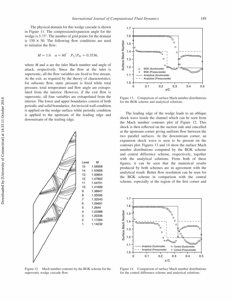
The physical domain for this wedge cascade is shown
in Figure 11. The compression/expansion angle for the
wedge is 5.738. The number of grid points for the domain
is 150 £ 50. The following flow conditions are used
to initialise the flow:
M ¼ 1:6 a ¼ 608 P2=P01 ¼ 0:3536;
where M and a are the inlet Mach number and angle of
attack, respectively. Since the flow at the inlet is
supersonic, all the flow variables are fixed to free stream.
At the exit, as required by the theory of characteristics,
for subsonic flow, static pressure is fixed while total
pressure, total temperature and flow angle are extrapo-
lated from the interior. However, if the exit flow is
supersonic, all four variables are extrapolated from the
interior. The lower and upper boundaries consist of both
periodic and solid boundaries. An inviscid wall condition
is applied on the wedge surface while periodic condition
is applied to the upstream of the leading edge and
downstream of the trailing edge.
The leading edge of the wedge leads to an oblique
shock wave inside the channel which can be seen from
the Mach number contours plot of Figure 12. This
shock is then reflected on the suction side and cancelled
at the upstream corner giving uniform flow between the
two parallel surfaces. At the downstream corner, an
expansion shock wave is seen to be present on the
contours plot. Figures 13 and 14 show the surface Mach
number distributions computed by the BGK scheme
and central difference scheme, respectively, together
with the analytical solutions. From both of these
figures, it can be seen that the numerical results
produced by both schemes are in agreement with the
analytical result. Better flow resolution can be seen for
the BGK scheme in comparison with the central
scheme, especially at the region of the first corner and
Figure 12. Mach number contours by the BGK scheme for thesupersonic wedge cascade flow.
Figure 13. Comparison of surface Mach number distributionsfor the BGK scheme and analytical solutions.
Figure 14. Comparison of surface Mach number distributionsfor the central difference scheme and analytical solutions.
International Journal of Computational Fluid Dynamics 189
Dow
nloa
ded
by [
Uni
vers
ity o
f C
onne
ctic
ut]
at 1
4:33
11
Oct
ober
201
4

parallel surfaces of the wedge cascade. The description
of the flow at the expansion corner is rather
unsatisfactory. Nonetheless, the numerical results
illustrated here are by far much better than the one
presented in Roe (1982). Another interesting aspect that
can be observed from Figures 13 and 14 is the shock
resolution capability of the BGK scheme where it is
better than the central difference scheme with TVD.
It can be seen that the BGK scheme is able to resolve
the shock location much better than the central
difference scheme with TVD.
For a more detailed analysis of the numerical results
presented above, the percentage errors for the Mach
number distributions on the suction and pressure sides of
the cascade are calculated for both the BGK and central
schemes. These are shown in Figures 15 and 16 for the
suction and pressure sides, respectively, where only a
few selected data points of interest are shown. Browsing
the percentage errors shown in these figures and
comparing the one from the BGK scheme with the
central scheme, one may observe that the percentage
error for the BGK scheme in general is less than the
central scheme.
3.3 Circular arc bump
The transonic flow over a circular arc bump is a typical
test case that is often used to assess the accuracy of the
numerical schemes. The descriptions of this test case
are taken from Ferziger and Peric (1996). The geometry
of the problem is shown in Figure 17 with a mesh size
of 181 £ 51. The thickness to chord ratio of the
circular arc is 10% with the chord length selected as
one unit. The length of the channel upstream and
downstream of the bump is chosen to be one unit as
well. The flow is initialised with a flow Mach number
of 0.675 at zero angle of attack. As for the boundaries,
the following conditions are applied. At the inlet, the
boundary condition is set according to the subsonic
flow. As for the outlet, the boundary condition is set
according to the theory of characteristics where for the
subsonic flow condition, static pressure is fixed and
three other flow variables are extrapolated from interior
points and for the supersonic flow condition, all flow
variables are extrapolated. The inviscid wall condition is
set at the lower and upper walls.
The contours for the Mach number for the BGK and
central schemes are shown in Figures 18 and 19,
respectively. As shown in the plots, there is a shock
occurring at the lower wall for a transonic flow
condition. Both of the schemes are able to predict the
location of this shock reasonably. The Mach number
distributions along the lower surface of the problem are
shown in Figure 20 for both the BGK scheme and
central scheme with TVD which are compared with the
numerical solution from Ferziger and Peric (1996). This
figure shows that both of the schemes are able to
resolve the shock and predict its location accurately.
However, the BGK scheme for inviscid flows is better
Figure 15. Percentage error distributions for the surface Machnumber on the suction side.
Figure 16. Percentage error distributions for the surface Machnumber on the pressure side. Figure 17. Physical mesh for the circular arc bump.
A.A. Omar et al.190
Dow
nloa
ded
by [
Uni
vers
ity o
f C
onne
ctic
ut]
at 1
4:33
11
Oct
ober
201
4

than the central scheme in describing the flow after the
shock, especially in regions close to the outlet when
compared to the solution provided by Ferziger and
Peric (1996).
4. Conclusion
A numerical solver based on the collisional BGK
model of the Boltzmann equation has been successfully
developed to simulate compressible inviscid flow.
Three test cases of this flow realm are selected to
assess the computational characteristics of the devel-
oped numerical solver. The computed results of the test
problems clearly demonstrate that the BGK scheme is
able to provide a very good resolution of the flow when
compared against the central difference scheme with
TVD and available exact solutions. In brief, this paper
concludes that the BGK scheme formulated via the
finite difference method is an accurate and robust
numerical scheme for computing 2D compressible
inviscid flows.
Acknowledgements
The authors would like to acknowledge the support of the
Institute of Research, Development and Commercialisation
(IRDC) under the project No. 600-IRDC/ST 5/3/887.
Figure 18. Mach number contours of the BGK scheme.
Figure 19. Mach number contours of the central scheme.
Figure 20. Comparison of Mach number distributions alongthe lower surface.
International Journal of Computational Fluid Dynamics 191
Dow
nloa
ded
by [
Uni
vers
ity o
f C
onne
ctic
ut]
at 1
4:33
11
Oct
ober
201
4

References
Abdusslam, S.N., Ong, J.C., Harun, M.M., Omar, A.A. and Asrar, W.,2006. Application of gas-kinetic BGK scheme for solving 2-Dcompressible inviscid flow around linear turbine cascade.International Journal for Computational Methods in EngineeringScience and Mechanics, 7 (6), 403–410.
Chae, D.S., Kim, C.A. and Rho, O.H., 2000. Development of animproved gas-kinetic BGK scheme for inviscid and viscous flows.Journal of Computational Physics, 158, 1–27.
Ferziger, J.H. and Peric, M., 1996. Computational methods in fluiddynamics. Germany: Springer, 287–289.
Fottner, L., 1990. Test cases for computation of internal flows inaero engine components. Advisory group for aerospace researchand development (AGARD), advisory report number 275,pp. 22–23.
Hirsch, C., 1990. The numerical computation of internaland external flows. vol. 2 Chapter 21 New York: John Wiley &Sons.
Hoffmann, K.A. and Chiang, S.T., 1993. Computational fluid dynamicsfor engineers. vol. 2, Chapters 11 and 14, Wichita, KS:Engineering education system.
Ong, J.C., 2004 Computational analysis of gas-kinetic BGK scheme forinviscid compressible flow, Thesis (MSc). University PutraMalaysia, Malaysia.
Ong, J.C., Omar, A.A. and Asrar, W., 2003. Evaluation of gas-kineticschemes for 1D inviscid compressible flow problem. InternationalJournal of Computational Engineering Science (IJCES), 4 (1),829–851.
Ong, J.C., Omar, A.A., Asrar, W. and Hamdan, M.M., 2004a.Development of gas-kinetic BGK scheme for two-dimensionalcompressible inviscid flows. AIAA paper 2004-2708.
Ong, J.C., Omar, A.A., Asrar, W. and Hamdan, M.M., 2004b. Animplicit gas-kinetic BGK scheme for two-dimensional compres-sible inviscid flows. AIAA Journal, 42 (7), 1293–1301.
Ong, J.C., Omar, A.A., Asrar, W. and Zaludin, Z.A., 2006. Gas-kineticBGK scheme for hypersonicflowsimulation.AIAApaper2006-0990.
Roe, P.L., 1982. Numerical methods in aeronautical fluid dynamics.London: Academic Press, 189–210.
Xu, K., 1998a. Gas-kinetic scheme for unsteady compressible flowsimulations. Von Karman institute for fluid dynamics lecture series.vol. 1998–03 Belgium: Von Karman Institute, Rhode St Genese.
Xu, K., 1998b. Gas-kinetic theory based flux splitting method for idealmagnetohydrodynamics. ICASE, Report, 98-53, November.
A.A. Omar et al.192
Dow
nloa
ded
by [
Uni
vers
ity o
f C
onne
ctic
ut]
at 1
4:33
11
Oct
ober
201
4