Embed Size (px)
Citation preview

Proudly 100% New Zealand owned and operated
CARREL-ELECTRADE LTDnot just products... solutions!
www.carrel-electrade.co.nz
Auckland661 Great South Road, PenroseTelephone: 09 525 1753Fax: 09 525 1756
Christchurch73B Brisbane Street
Telephone: 03 366 1242Fax: 03 379 1991
FINDER’S RANGE OF DIN MOUNTED TIMERS
80 & 83 SERIES
MULTI-VOLTAGE & MULTI-FUNCTION


www.carrel-electrade.co.nz
1
Proudly 100% New Zealand owned and operated
Carrel-Electrade Ltd is the new force in Electrical Control and Automation in New Zealand. As manufacturers, importers and distributors of electrical equipment the company has more than 60 years of history and experience behind it, cementing its status as one of New Zealand’s major suppliers of specialised electrical measuring and control equipment to industry.
The company maintains long-standing values such as service, dependability and
our on demand.
Our range of products provide customers with cost effective solutions from the not
power supply/power generation sectors.
Carrel-Electrade Ltd is New Zealand’s only manufacturer of analogue panel instruments, timber moisture meters and electrical transducers.
Our T Series and LP Series electrical transducers, as with all products we manufacture, have been designed to meet the requirements of international standards and meticulous attention is paid to the quality and robustness of the units.
The latest range of “intelligent” transducers feature the ability to communicate directly with PLC’s, computers and SCADA systems.
Our design and development team has wide experience in analogue and digital circuitry and we specialise in measuring and monitoring electrical systems.
In addition to standard products we work closely with end users to develop specialised
of standard products, or completely new designs. When coupled with the experience and expertise of our technical and sales staff and our national distribution network with warehouses in Auckland and Christchurch, Carrel-Electrade Ltd truly offer…
not just products... solutions!
Visit our website at:
Contact us:
Auckland661 Great South RoadPenroseP.O. Box 11078EllerslieTelephone: 09 525 1753Fax: 09 525 1756
Christchurch73B Brisbane StreetChristchurchTelephone: 03 366 1242Fax: 03 379 1991
Our Sales TeamBusiness Development ManagerWayne Lewis0274 329 737Technical ManagerColin Wichman0274 532 649Hazardous Area SpecialistRichard Woolhouse0274 728 704AucklandRik Higgott0275 858 614AucklandGarrie Taylor0275 912 299Waikato, Bay of PlentyGuy Burgess0274 979 247Wellington, Central North Island (West), Nelson, MarlboroughSteve Fieldhouse0274 438 181Hawkes Bay, Central North Island (East)Glyn Clements0274 321 356Canterbury, Otago, SouthlandMark Booth0274 358 668Christchurch, West CoastMartin Laws0274 979 248
Webwww.carrel-electrade.co.nz
CARREL-ELECTRADE LTDnot just products... solutions!

3
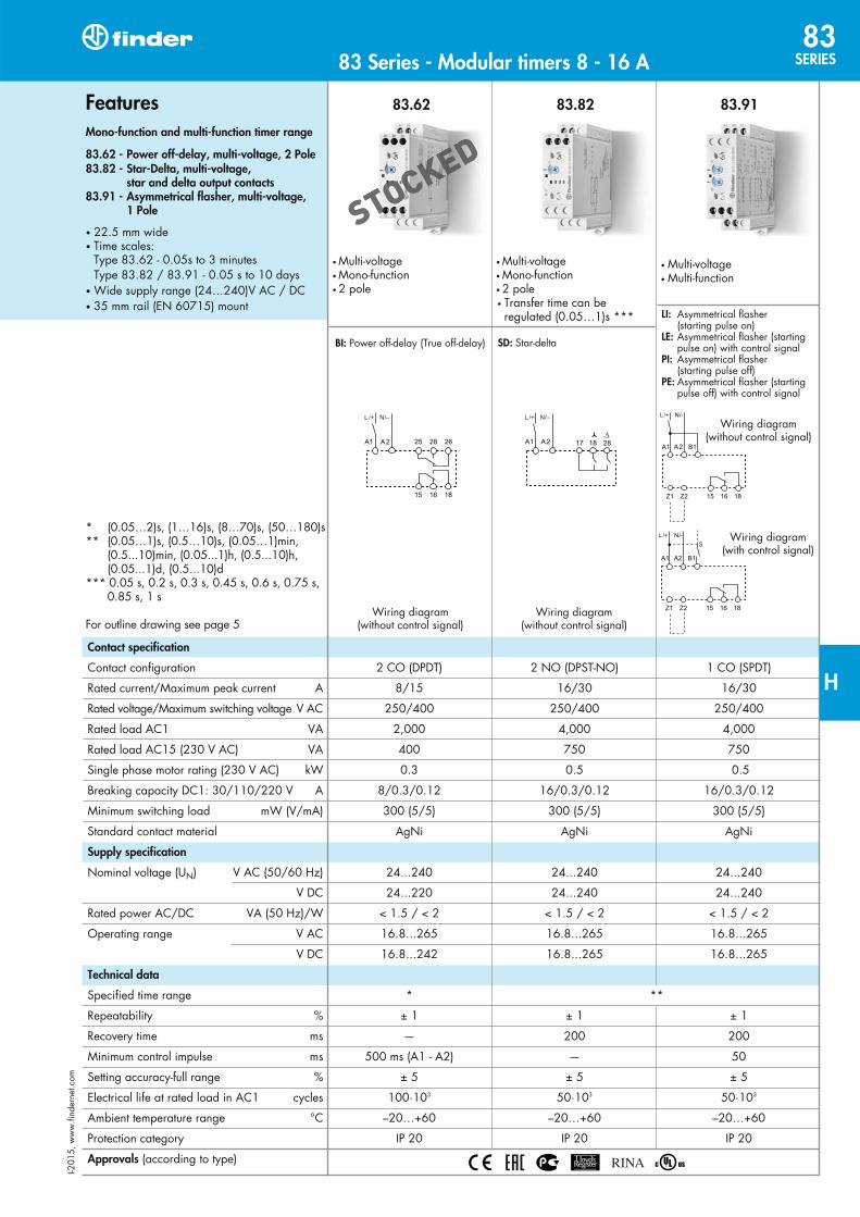
83.62 83.82 83.91
LI:
LE:
PI:
PE:
BI:
Contact specification
Supply specification
Technical data
Approvals
FeaturesMono-function and multi-function timer range
83.62 - Power off-delay, multi-voltage, 2 Pole83.82 - Star-Delta, multi-voltage, star and delta output contacts83.91 - Asymmetrical flasher, multi-voltage, 1 Pole
SD:
83 Series - Modular timers 8 - 16 A83
SERIES
H
STTTTTTTTTTTTTTTTTTOOOOOOOOOOOOOOOOOOOOOOCCCCCCCCCCCCCCCKKKKKKKKKKKEEEEEEEEEEEDDDD

83.01 83.02 83.52
AI: DI: GI: SW: BE: CE: DE: WD:
AI: DI: GI: SW: BE: CE: DE: WD:
AE: EEa:
FE: GE: IT: BEp:
DEp:
SHp:
Contact specification
Supply specification
Technical data
Approvals
1
FeaturesMulti-function timer range
83.01 - Multi-function & multi-voltage, 1 Pole83.02 - Multi-function & multi-voltage, 2 Pole (timed + instantaneous options), external time setting potentiometer option83.52 - Multi-function & multi-voltage, 2 Pole (timed + instantaneous options), external time setting potentiometer option, pause function option
83 Series - Modular timers 12 - 16 A83
SERIES
H
STTTTTTTTTTTTTTTTTTTTTTTTTTOOOOOOOOOOOOOOOOOOOOOOOOOOOCCCCCCCCCCCCCCCCKKKKKKKKKKKKKKEEEEEEEEEEEDDDD
STSTTTTTTTTTOOOOOOOOOOOOOOOOOOOOOOOOOOOCCCCCCCCCCCCCCCCCCKKKKKKKKKKKKKKKEEEEEEEEEEEEDDDDDD

6
Functions
060.72
AccessoriesSheet of marker tags,
087.02.2
Potentiometer
83SERIE S 83 Series - Modular timers 16 A
H
STOCKEDKED
TTTTTTTTTTTTTTTTTTTTTTTTTTOOOOOOOOOOOOOOOOOOOOOOOOOOOOOOOOOOOOOOOOOOOOOOOOOOOCCCCCCCCCCCCCCCCCCCCCCCCCCCCCCCCCCCCCCCCCCCCCCCCCCCKKKKKKKKKKKKKKKKKKKKKKKKKKKKKKKKKKKKKKKE
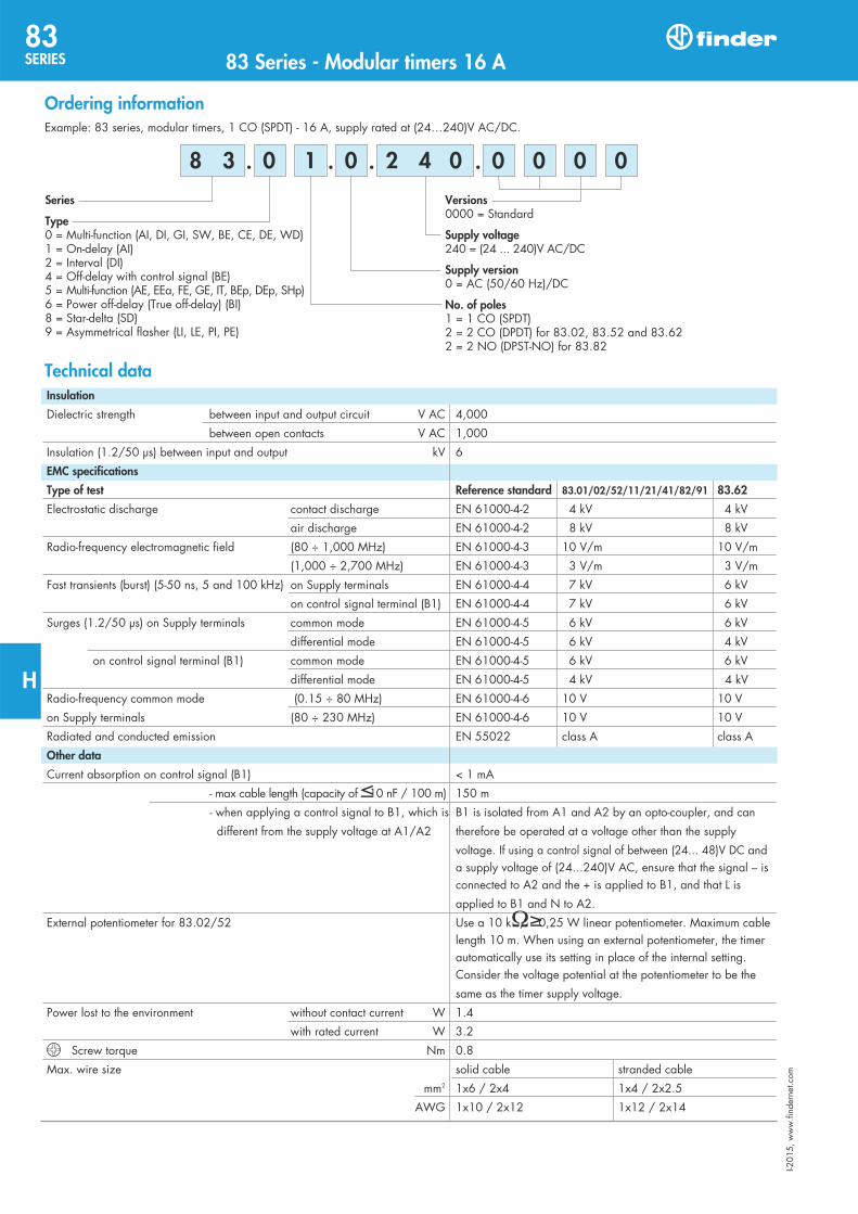
Versions
Supply voltage
Supply version
No. of poles
Series
Type
0 1 0
Ordering information
. . . . 2 4 0 8 3
Insulation
EMC specifications
Type of test Reference standard 83.01/02/52/11/21/41/82/91 83.62
Other data
Technical data
4
0 0 0 0
83SERIE S 83 Series - Modular timers 16 A
H

7
Multi-function Type83.0183.02
(AI) On-delay.
(DI) Interval.
(GI) Pulse delayed.
(SW) Symmetrical flasher (starting pulse on).
(BE) Off-delay with control signal.
(CE) On- and off-delay with control signal.
(DE) Interval with control signal on.
(WD) Watchdog (Retriggerable interval with control signal on).
Wiring diagram
83.02 type
Contact mode selector Functions without control signal (example: AI) Functions with control signal (example: BE)
Functions U S
83 Series - Modular timers 16 A83
SERIES
H
8
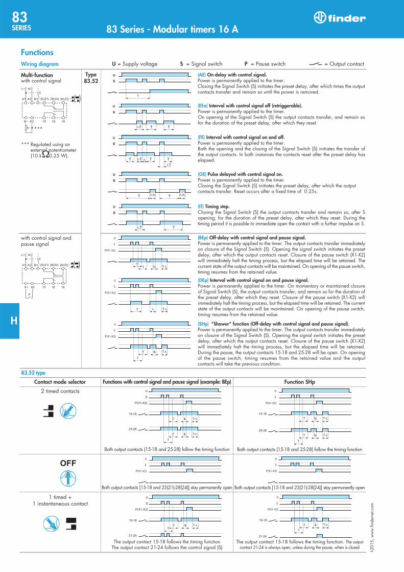
Multi-function Type83.52
(AE) On-delay with control signal.
Wiring diagram
T
(EEa) Interval with control signal off (retriggerable).
(FE) Interval with control signal on and off.
(GE) Pulse delayed with control signal on.
(IT) Timing step.
(BEp) Off-delay with control signal and pause signal.
(DEp) Interval with control signal on and pause signal.
(SHp) “Shower” function (Off-delay with control signal and pause signal).
Functions U S P
83.52 type
Contact mode selector Functions with control signal and pause signal (example: BEp) Function SHp
83SERIE S 83 Series - Modular timers 16 A
H
9
83.91Asymmetrical recycler
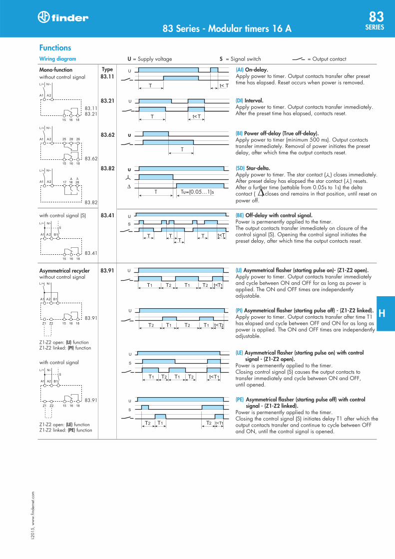
Mono-function Type83.11
(AI) On-delay.
(DI) Interval.
(BI) Power off-delay (True off-delay).
(SD) Star-delta.
(BE) Off-delay with control signal.
(LI) Asymmetrical flasher (starting pulse on)- (Z1-Z2 open).
(PI) Asymmetrical flasher (starting pulse off) - (Z1-Z2 linked).
(LE) Asymmetrical flasher (starting pulse on) with control signal - (Z1-Z2 open).
(PE) Asymmetrical flasher (starting pulse off) with control signal - (Z1-Z2 linked).
(LI)(PI)
(LE)(PE)
Wiring diagram
Functions
83.62
83.21
83.82
83.41
U S
83 Series - Modular timers 16 A83
SERIES
H
5
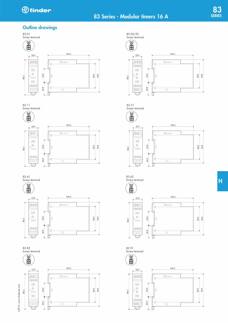
Outline drawings
83 Series - Modular timers 16 A83
SERIES
H

80.61 80.82
4
Wiring diagram(without control signal)
Multi-voltageMono-functionTransfer time can be regulated (0.05…1)s
SD: Star-delta
FeaturesMono-function timer range
80.61 - Power off-delay (True off-delay), multi-voltage80.82 - Star-delta, multi-voltage
17.5 mm wideRotary range selector, and timing trimmerFour time scales from 0.05s to 3 min (type 80.61)Six time scales from 0.1s to 20min (type 80.82)High input/output isolation35 mm rail (EN 60715) mount
1 CO (SPDT) 2 NO (DPST-NO)
8/15 6/10
250/400 250/400
2,000 1,500
400 300
0.3 —
8/0.3/0.12 6/0.2/0.12
300 (5/5) 500 (12/10)
AgNi AgNi
24...240 24...240
24…220 24...240
< 0.6/ < 0.6 < 1.3/ < 0.8
16.8...265 16.8...265
16.8...242 16.8...265
(0.05…2)s, (1…16)s, (8…70)s, (50…180)s (0.1...2)s, (1...20)s, (0.1...2)min, (1...20)min
± 1 ± 1
— 100
500 (A1-A2) —
± 5 ± 5
100·103 60·103
–10…+50 –10…+50
IP 20 IP 20
Multi-voltageMono-function
Contact specification
Contact configuration
Rated current/Maximum peak current A
Rated voltage/Maximum switching voltage V AC
Rated load AC1 VA
Rated load AC15 (230 V AC) VA
Single phase motor rating (230 V AC) kW
Breaking capacity DC1: 30/110/220 V A
Minimum switching load mW (V/mA)
Standard contact material
Supply specification
Nominal voltage (UN) V AC (50/60 Hz)
V DC
Rated power AC/DC VA (50 Hz)/W
Operating range V AC
V DC
Technical data
Specified time range
Repeatability %
Recovery time ms
Minimum control impulse ms
Setting accuracy-full range %
Electrical life at rated load in AC1 cycles
Ambient temperature range °C
Protection category
Approvals (according to type)
BI: Power off-delay (True off-delay)
Wiring diagram(without control signal)
80.61 / 80.82Screw terminal
FOR UL RATINGS SEE: “General technical information” page
For outline drawing see page 6
III-2
015,
ww
w.fi
nder
net.c
om
80SERIE S 80 Series - Modular timers 6 - 8 A
H
STTOOOOOOOOOOOOOOOOOOOOCCCCCCCCCCCCCCCCCCCCCCCCCCCCCCCCCCCCCCCCCCCCKKKKKKKKKKKEEEEEEEEEEEDD
STOCKED
STTTTTTTTTTTTTTTTTTTTTTTTTTTTTTTTTTTTTTTTTTTTTTTTTTTTTTOOOOOOOOOOOOOOOOOOOOOOOOOOOOOOOOOOOOOOOOOOOOOOOOOOOOOOOOOOOOOOOOOCCCCCCCCCCCCCCCCCCCCCKKKKKKKKKKKKKKKKKKEEEEED
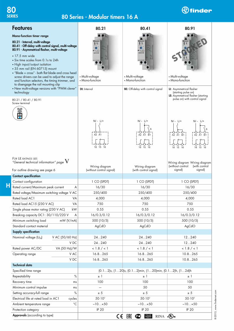
80.21 80.41 80.91
Multi-voltageMono-function
LI: Asymmetrical flasher (starting pulse on) LE: Asymmetrical flasher (starting pulse on) with control signal
Wiring diagram(without control
signal)
Wiring diagram(with control
signal)
1 CO (SPDT) 1 CO (SPDT) 1 CO (SPDT)
16/30 16/30 16/30
250/400 250/400 250/400
4,000 4,000 4,000
750 750 750
0.55 0.55 0.55
16/0.3/0.12 16/0.3/0.12 16/0.3/0.12
500 (10/5) 500 (10/5) 500 (10/5)
AgCdO AgCdO AgCdO
24...240 24...240 12...240
24...240 24...240 12...240
< 1.8 / < 1 < 1.8 / < 1 < 1.8 / < 1
16.8...265 16.8...265 10.8...265
16.8...265 16.8...265 10.8...265
(0.1…2)s, (1…20)s, (0.1…2)min, (1…20)min, (0.1…2)h, (1…24)h
± 1 ± 1 ± 1
100 100 100
— 50 50
± 5 ± 5 ± 5
50·103 50·103 50·103
–10…+50 –10…+50 –10…+50
IP 20 IP 20 IP 20
Multi-voltageMono-function
DI: Interval
Wiring diagram(without control signal)
Contact specification
Contact configuration
Rated current/Maximum peak current A
Rated voltage/Maximum switching voltage V AC
Rated load AC1 VA
Rated load AC15 (230 V AC) VA
Single phase motor rating (230 V AC) kW
Breaking capacity DC1: 30/110/220 V A
Minimum switching load mW (V/mA)
Standard contact material
Supply specification
Nominal voltage (UN) V AC (50/60 Hz)
V DC
Rated power AC/DC VA (50 Hz)/W
Operating range V AC
V DC
Technical data
Specified time range
Repeatability %
Recovery time ms
Minimum control impulse ms
Setting accuracy-full range %
Electrical life at rated load in AC1 cycles
Ambient temperature range °C
Protection category
Approvals (according to type)
FeaturesMono-function timer range
80.21 - Interval, multi-voltage80.41 - Off-delay with control signal, multi-voltage80.91 - Asymmetrical flasher, multi-voltage
17.5 mm wideSix time scales from 0.1s to 24hHigh input/output isolation35 mm rail (EN 60715) mount“Blade + cross” - both flat blade and cross head
screw drivers can be used to adjust the range and function selectors, the timing trimmer, and to disengage the rail mounting clip New multi-voltage versions with “PWM clever”
technology
80.21 / 80.41 / 80.91Screw terminal
FOR UL RATINGS SEE: “General technical information” page
For outline drawing see page 6Wiring diagram
(with control signal)
Multi-voltageMono-function
BE: Off-delay with control signal
2
III-2
015,
ww
w.fi
nder
net.c
om
80SERIE S 80 Series - Modular timers 16 A
H
STSTTTTTTTTTTTTOOOOOOOOOOOOOOOOOOOOOOOOOOOOOOOOOOOOOOOOOOOOOOOOOOOOOOOOOOOOOOOOOOOOOOOOOOOOOOOOOOOCCCCCCCCCCCCCCCCCCCCCCCCCCCCCCCCCCCCCCCCCCCCCCCCCCCCCCCCCCCCKKKKKKKKKKKKKKKKKEEEEEEEEEEEEEEEEEEDDD

80.01 80.11
1 CO (SPDT) 1 CO (SPDT)
16/30 16/30
250/400 250/400
4,000 4,000
750 750
0.55 0.55
16/0.3/0.12 16/0.3/0.12
500 (10/5) 500 (10/5)
AgCdO AgCdO
12…240 24...240
12…240 24...240
< 1.8 / < 1 < 1.8 / < 1
10.8...265 16.8...265
10.8...265 16.8...265
(0.1…2)s, (1…20)s, (0.1…2)min, (1…20)min, (0.1…2)h, (1…24)h
± 1 ± 1
100 100
50 —
± 5 ± 5
50·103 50·103
–10…+50 –10…+50
IP 20 IP 20
Wiring diagram(without control signal)
Multi-voltageMono-function
Multi-voltageMulti-function
AI: On-delayDI: IntervalSW: Symmetrical flasher (starting pulse on)BE: Off-delay with control signalCE: On- and off-delay with control signalDE: Interval with control signal on
AI: On-delay
Wiring diagram(with control signal)
Wiring diagram(without control signal)
Contact specification
Contact configuration
Rated current/Maximum peak current A
Rated voltage/Maximum switching voltage V AC
Rated load AC1 VA
Rated load AC15 (230 V AC) VA
Single phase motor rating (230 V AC) kW
Breaking capacity DC1: 30/110/220 V A
Minimum switching load mW (V/mA)
Standard contact material
Supply specification
Nominal voltage (UN) V AC (50/60 Hz)
V DC
Rated power AC/DC VA (50 Hz)/W
Operating range V AC
V DC
Technical data
Specified time range
Repeatability %
Recovery time ms
Minimum control impulse ms
Setting accuracy-full range %
Electrical life at rated load in AC1 cycles
Ambient temperature range °C
Protection category
Approvals (according to type)
1
FeaturesMulti-function and mono-function timer range
80.01 - Multi-function & multi-voltage80.11 - On-delay, multi-voltage
17.5 mm wideSix time scales from 0.1s to 24hHigh input/output isolation35 mm rail (EN 60715) mount“Blade + cross” - both flat blade and cross head
screw drivers can be used to adjust the range and function selectors, the timing trimmer, and to disengage the rail mounting clip New multi-voltage versions with “PWM clever”
technology
80.01 / 80.11Screw terminal
FOR UL RATINGS SEE: “General technical information” page
For outline drawing see page 6
III-2
015,
ww
w.fi
nder
net.c
om80 Series - Modular timers 16 A
80SERIES
H
STSTTTTTTTTTTTTTTTTTOOOOOOOOOOOOOOOOOOOOOOOOOOOOOOOOOOOOOOOOOOOOOOOOOOOOOCCCCCCCCCCCCCCCCCCCCCCKKKKKKKKKKKKKKKKKEEEEEEEEEEEEEEEDD

(AI) On-delay.Apply power to timer. Output contacts transfer after presettime has elapsed. Reset occurs when power is removed.
(DI) Interval.Apply power to timer. Output contacts transfer immediately. After the preset time has elapsed, contacts reset.
(SW) Symmetrical flasher (starting pulse on).Apply power to timer. Output contacts transfer immediately and cycle between ON and OFF for as long as power isapplied. The ratio is 1:1 (time on = time off).
(BE) Off-delay with control signal.Power is permenently applied to the timer. The outputcontacts transfer immediately on closure of the SignalSwitch (S). Opening the Signal Switch initiates the presetdelay, after which time the output contacts reset.
(DE) Interval with control signal on.Power is permenently applied to the timer.On momentary or maintained closure of Signal Switch (S),the output contacts transfer, and remain so for the durationof the preset delay, after which they reset.
(CE) On- and off-delay with control signal.Power is permenently applied to the timer. Closing theSignal Switch (S) initiates the preset delay, after which timethe output contacts transfer. Opening the Signal switchinitiates the same preset delay, after which time the outputcontacts reset.
Functions
With control signal
Without control signal Type80.0180.71
Contacts NO output contactSupply voltageLED*
OFF
ON
ON
ON
U = Supply voltage
S = Signal switch
= Output contactOpen
Open
Open(Timing in Progress)
Closed
15 - 18
15 - 18
15 - 18
15 - 16
15 - 16
15 - 16
15 - 16
15 - 18
Open Closed
* The LED on type 80.61 is illuminated only when the supply voltage is applied to the timer; during the timing period the LED is not illuminated.
NOTE: The function must be set before energising the timer.
control signal terminal B1.
* With DC supply, positive polarity has to be connected to B1 terminal (according to EN 60204-1).
A1 - A2 = 230 V AC B1 - A2 = 12 V DC
Wiring diagram
80.0180.71
80.71
80.01
80.71
80.01
7
Without control signal = Start via contact in supply line (A1).With control signal = Start via contact into control terminal (B1).
III-2
015,
ww
w.fi
nder
net.c
om80 Series - Modular timers 1 - 6 - 8 - 16 A
80SERIES
H
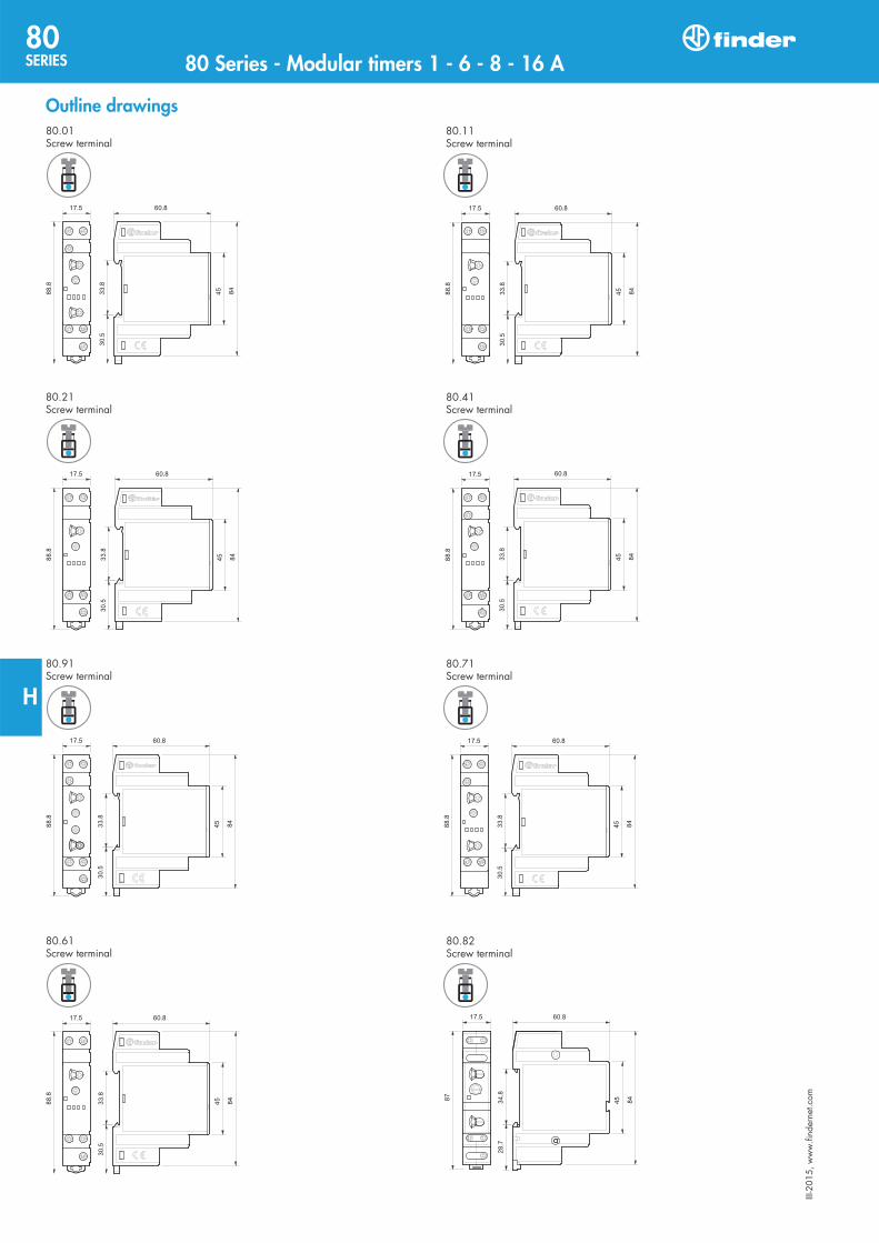
6
Outline drawings80.01Screw terminal
80.11Screw terminal
80.21Screw terminal
80.41Screw terminal
80.91Screw terminal
80.71Screw terminal
80.61Screw terminal
80.82Screw terminal
III-2
015,
ww
w.fi
nder
net.c
om
80SERIE S 80 Series - Modular timers 1 - 6 - 8 - 16 A
H
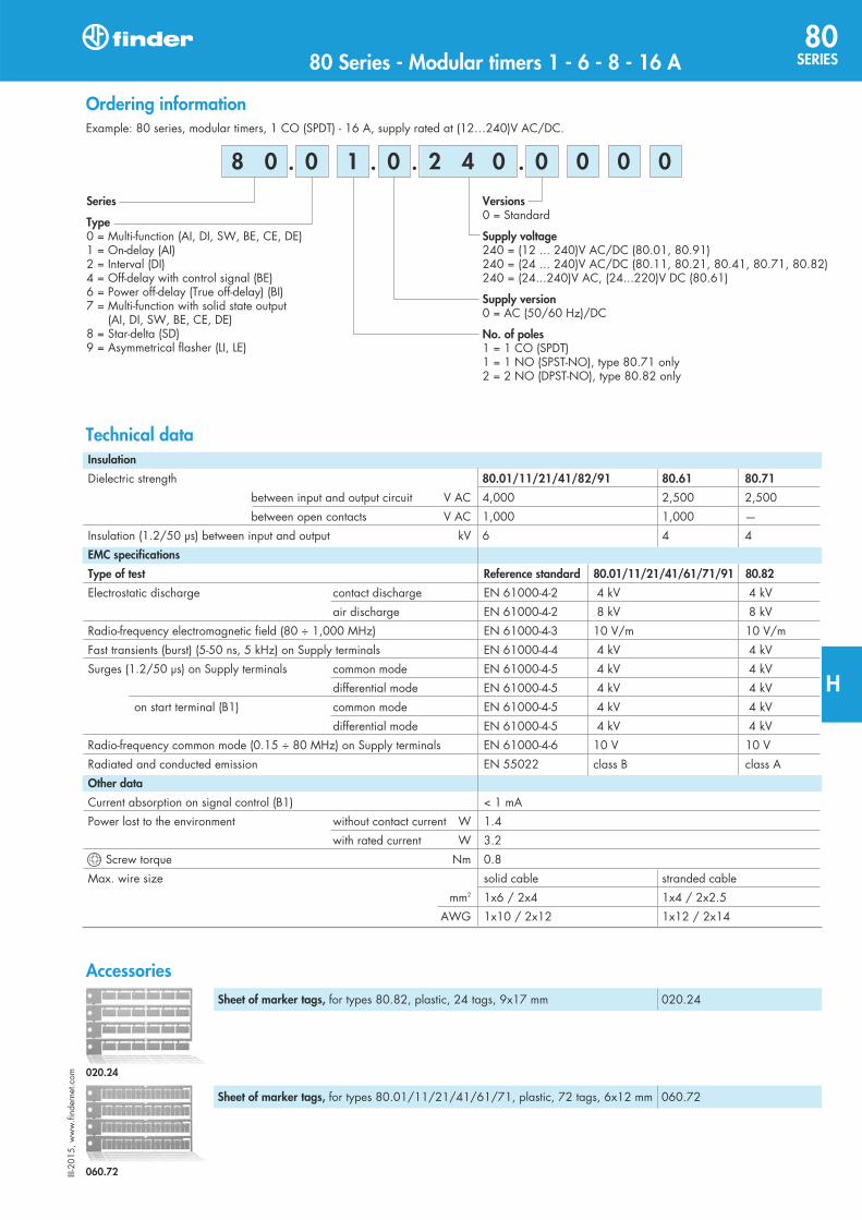
Example: 80 series, modular timers, 1 CO (SPDT) - 16 A, supply rated at (12…240)V AC/DC.
Versions0 = Standard
Supply voltage240 = (12 ... 240)V AC/DC (80.01, 80.91)240 = (24 ... 240)V AC/DC (80.11, 80.21, 80.41, 80.71, 80.82)240 = (24...240)V AC, (24...220)V DC (80.61)
Supply version0 = AC (50/60 Hz)/DC
No. of poles1 = 1 CO (SPDT)1 = 1 NO (SPST-NO), type 80.71 only2 = 2 NO (DPST-NO), type 80.82 only
Series
Type0 = Multi-function (AI, DI, SW, BE, CE, DE)1 = On-delay (AI)2 = Interval (DI)4 = Off-delay with control signal (BE)6 = Power off-delay (True off-delay) (BI)7 = Multi-function with solid state output
(AI, DI, SW, BE, CE, DE)8 = Star-delta (SD)9 = Asymmetrical flasher (LI, LE)
0 1 0 0 0 0 0
Ordering information
. . . . 2 4 0 8 0
Insulation
Dielectric strength 80.01/11/21/41/82/91 80.61 80.71
between input and output circuit V AC 4,000 2,500 2,500
between open contacts V AC 1,000 1,000 —
Insulation (1.2/50 µs) between input and output kV 6 4 4
EMC specifications
Type of test Reference standard 80.01/11/21/41/61/71/91 80.82
Electrostatic discharge contact discharge EN 61000-4-2 4 kV 4 kV
air discharge EN 61000-4-2 8 kV 8 kV
Radio-frequency electromagnetic field (80 ÷ 1,000 MHz) EN 61000-4-3 10 V/m 10 V/m
Fast transients (burst) (5-50 ns, 5 kHz) on Supply terminals EN 61000-4-4 4 kV 4 kV
Surges (1.2/50 µs) on Supply terminals common mode EN 61000-4-5 4 kV 4 kV
differential mode EN 61000-4-5 4 kV 4 kV
on start terminal (B1) common mode EN 61000-4-5 4 kV 4 kV
differential mode EN 61000-4-5 4 kV 4 kV
Radio-frequency common mode (0.15 ÷ 80 MHz) on Supply terminals EN 61000-4-6 10 V 10 V
Radiated and conducted emission EN 55022 class B class A
Other data
Current absorption on signal control (B1) < 1 mA
Power lost to the environment without contact current W 1.4
with rated current W 3.2
Screw torque Nm 0.8
Max. wire size solid cable stranded cable
mm2 1x6 / 2x4 1x4 / 2x2.5 AWG 1x10 / 2x12 1x12 / 2x14
Technical data
AccessoriesSheet of marker tags, for types 80.82, plastic, 24 tags, 9x17 mm 020.24
5
Sheet of marker tags, for types 80.01/11/21/41/61/71, plastic, 72 tags, 6x12 mm 060.72
020.24
060.72III-2
015,
ww
w.fi
nder
net.c
om80 Series - Modular timers 1 - 6 - 8 - 16 A
80SERIES
H