Embed Size (px)
Citation preview

FINANCE, RISK, & SUPPLY CHAIN MANAGEMENTSupply Chain Management
City of Vancouver, Finance, Risk, & Supply Chain Management Supply Chain Management 453 West 12th Avenue Vancouver, British Columbia V5Y 1V4 Canada tel: 604.873.7263 fax: 604.873.7057 website: vancouver.ca
March 8, 2017
INVITATION TO TENDER “ITT” NO. PS20162048 KITSILANO COMMUNITY CENTER ENERGY RETROFIT CONSTRUCTION
AMENDMENT No. 2
A) RE: DRAWING E4 – COMMUNITY CENTER LOWER FLOOR PLAN
THE FOLLOWING IS ADDED:
Detail 1: Community Centre – Lower Floor
i) Route wiring and conductor for the new CDP#1 panel in the ceiling space of thelower floor corridor or 12’ AFF of the upper level gymnasium.
B) RE: DRAWING E5 – COMMUNITY CENTER UPPER FLOOR AND MECHANICAL ROOMS
THE FOLLOWING IS ADDED:
Detail 2: Mech Room – Upper Plan – New
i) New Panels ‘M1’ and ‘CDP#1’ shall be relocated to the north wall.
C) RE: DRAWING S201
THE FOLLOWING IS ADDED:
i) Drawing S201 Addendum 01 dated 2017/02/22.
D) RE: DRAWING M-2.1: ICE RINK PARTIAL PLAN – AREA 1
THE FOLLOWING IS AMENDED:
Drawing Notes:
i) The last drawing note labeled 15 to be changed from 15 to 16.
ii) Note 16 shall refer to the new mechanical room doors (RM37).
E) RE: DRAWING M-4.1: ICE RINK HEATING SYSTEM SCHEMATIC - NEW
THE FOLLOWING IS AMENDED:
Storage Tank T-1 Detail
Drawing Notes:
i) Note 3 shall be revised to read: “Tank drain 1.5”
ii) Note 4 shall be revised to read: “Saddles for tank”
INVITATION TO TENDER “ITT” NO. PS20162048 KITSILANO COMMUNITY CENTER ENERGY RETROFIT CONSTRUCTION
AMENDMENT No. 2
Page 2 of 3
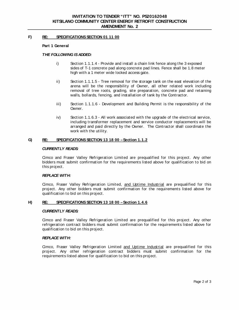
F) RE: SPECIFICATIONS SECTION 01 11 00
Part 1 General
THE FOLLOWING IS ADDED:
i) Section 1.1.1.4 - Provide and install a chain link fence along the 3 exposedsides of T-1 concrete pad along concrete pad lines. Fence shall be 1.8 meterhigh with a 1 meter wide locked access gate.
ii) Section 1.1.1.5 - Tree removal for the storage tank on the east elevation of thearena will be the responsibility of Owner, all other related work includingremoval of tree roots, grading, site preparation, concrete pad and retainingwalls, bollards, fencing, and installation of tank by the Contractor.
iii) Section 1.1.1.6 - Development and Building Permit is the responsibility of theOwner.
iv) Section 1.1.6.3 - All work associated with the upgrade of the electrical service,including transformer replacement and service conductor replacements will bearranged and paid directly by the Owner. The Contractor shall coordinate thework with the utility.
G) RE: SPECIFICATIONS SECTION 13 18 00 – Section 1.1.2
CURRENTLY READS:
Cimco and Fraser Valley Refrigeration Limited are prequalified for this project. Any other bidders must submit confirmation for the requirements listed above for qualification to bid on this project.
REPLACE WITH:
Cimco, Fraser Valley Refrigeration Limited, and Uptime Industrial are prequalified for this project. Any other bidders must submit confirmation for the requirements listed above for qualification to bid on this project.
H) RE: SPECIFICATIONS SECTION 13 18 00 – Section 1.4.6
CURRENTLY READS:
Cimco and Fraser Valley Refrigeration Limited are prequalified for this project. Any other refrigeration contract bidders must submit confirmation for the requirements listed above for qualification to bid on this project.
REPLACE WITH:
Cimco, Fraser Valley Refrigeration Limited and Uptime Industrial are prequalified for this project. Any other refrigeration contract bidders must submit confirmation for the requirements listed above for qualification to bid on this project.

INVITATION TO TENDER “ITT” NO. PS20162048 KITSILANO COMMUNITY CENTER ENERGY RETROFIT CONSTRUCTION
AMENDMENT No. 2
Page 3 of 3
I) RE: SPECIFICATIONS
THE FOLLOWING IS ADDED:
Section 23 21 13 03 Hydronic Systems Aquatherm:
The new specification is included as an 8 page attachment to this Amendment 2
All other conditions and specifications remain unchanged.
This amendment must be completed, and attached to your Tender form.
If you have already submitted your Tender, this amendment shall be submitted to the Supply Chain Management office, 4th Floor, City of Vancouver, 453 West 12th Avenue, Vancouver, British Columbia, Canada, V5Y 1V4, and must be received in the drop box at the Supply Chain Management office prior to the Closing Time in an envelope clearly marked “AMENDMENT No. 2 to ITT. No. PS20162048 – Kitsilano Community Center Energy Retrofit Construction”.
NAME OF VENDOR
________________________________________ SIGNATURE OF AUTHORIZED SIGNATORY
DATE
Contracting Specialist: Eamonn Savage

Kitsilano CC And Arena Heating Upgrade 23 21 13.03 HYDRONIC SYSTEMS – Aquatherm
Project No. 2015029
Prism Engineering Ltd. Page 1
Part 1 General
1.1 RELATED REQUIREMENTS
.1 Section 23 05 05 - Installation of Pipe Work
.2 Section 23 05 23.01 - Valves - Bronze
.3 Section 23 05 23.02 - Valves - Cast Iron: Gate, Globe, Check
.4 Section 23 05 93 - Testing, Adjusting and Balancing
.5 Section 23 08 02 - Cleaning and Start-Up
1.2 SUMMARY
.1 Section Includes.
.1 Materials and installation for steel piping, valves and fittings for hydronic systems
services piping.
1.3 REFERENCES
.1 American Society of Mechanical Engineers (ASME).
.1 ASME B16.1-98, Cast Iron Pipe Flanges and Flanged Fittings.
.2 ASME B16.3-98, Malleable Iron Threaded Fittings.
.3 ASME B16.5-03, Pipe Flanges and Flanged Fittings.
.4 ASME B16.9-01, Factory-Made Wrought Buttwelding Fittings.
.5 ASME B18.2.1-03, Square and Hex Bolts and Screws (Inch Series).
.6 ASME B18.2.2-87(R1999), Square and Hex Nuts (Inch Series).
.2 American Society for Testing and Materials International, (ASTM).
.1 ASTM F 2389-07 - Standard Specification for Pressure-rated Polypropylene (PP)
Piping Systems
.2 CSA B137.11 - Polypropylene (PP-R) Pipe and Fittings for Pressure Applications
.3 NSF/ANSI 14 – Plastic Piping System Components and Related Materials
.4 ASTM A47/A47M-99, Standard Specification for Ferritic Malleable Iron
Castings.
.5 ASTM A53/A53M-02, Standard Specification for Pipe, Steel, Black and
Hot-Dipped, Zinc Coated Welded and Seamless.
.6 ASTM A536-84(1999)e1, Standard Specification for Ductile Iron Castings.
.7 ASTM B61-02, Standard Specification for Steam or Valve Bronze Castings.
.8 ASTM B62-02, Standard Specification for Composition Bronze or Ounce Metal
Castings.

Kitsilano CC And Arena Heating Upgrade 23 21 13.03 HYDRONIC SYSTEMS – Aquatherm Project No. 2015029
Prism Engineering Ltd. Page 2
.9 ASTM E202-00, Standard Test Method for Analysis of Ethylene Glycols and
Propylene Glycols.
.3 American Water Works Association (AWWA).
.1 AWWA C111-00, Rubber-Gasket Joints for Ductile-Iron Pressure Pipe and
Fittings.
.4 Canadian Standards Association (CSA International).
.1 CSA B242-M1980(R1998), Groove and Shoulder Type Mechanical Pipe
Couplings.
.2 CAN/CSA W48-01, Filler Metals and Allied Materials for Metal Arc Welding
(Developed in cooperation with the Canadian Welding Bureau).
.5 Manufacturer's Standardization of the Valve and Fittings Industry (MSS).
.1 MSS-SP-67-025, Butterfly Valves.
.2 MSS-SP-70-98, Cast Iron Gate Valves, Flanged and Threaded Ends.
.3 MSS-SP-71-97, Cast Iron Swing Check Valves Flanged and Threaded Ends.
.4 MSS-SP-80-03, Bronze Gate, Globe, Angle and Check Valves.
.5 MSS-SP-85-02, Cast Iron Globe and Angle Valves, Flanged and Threaded Ends.
1.4 SUBMITTALS
.1 Material list naming each product to be used identified by manufacturer and
product number, in accordance with Section 01 33 00.
1.5 QUALITY ASSURANCE
.1 Material shall be certified by NSF International as complying with NSF 14, and
ASTM F 2389 or CSA B137.11.
.2 Material shall comply with manufacturer’s specifications.
.3 Special Engineered products shall be certified by NSF International as complying
with NSF 14.
Part 2 Products
2.1 PIPE AND PIPING PRODUCTS
.1 Pipe shall be manufactured from a PP-R resin (Fusiolen) meeting the short-term
properties and long-term strength requirements of ASTM F 2389 or CSA
B137.11. The pipe shall contain no rework or recycled materials except that
generated in the manufacturer's own plant from resin of the same specification
from the same raw material. All pipe shall be made in an extrusion process.
Hydronic hot water and heating piping shall contain a fiber layer (faser) to restrict
thermal expansion. All pipe shall comply with the rated pressure requirements of

Kitsilano CC And Arena Heating Upgrade 23 21 13.03 HYDRONIC SYSTEMS – Aquatherm Project No. 2015029
Prism Engineering Ltd. Page 3
ASTM F 2389 or CSA B137.11. All pipe shall be certified by NSF International
as complying with NSF 14, and ASTM F 2389 or CSA B137.11.
.2 Pipe shall be Aquatherm® Green Pipe® MF® or Blue Pipe® MF®, available
from Aquatherm, NA. Piping specifications and ordering information are
available at www.aquatherm.com.
2.2 FITTINGS
.1 Fittings shall be manufactured from a PP-R resin (Fusiolen) meeting the short-
term properties and long-term strength requirements of ASTM F 2389. The
fittings shall contain no rework or recycled materials except that generated in the
manufacturer's own plant from resin of the same specification from the same raw
material. All fittings shall be certified by NSF International as complying with
NSF 14, and ASTM F 2389 or CSA B137.11.
.2 Fittings shall be Aquatherm® Green Pipe® or Blue Pipe® available from
Aquatherm, NA. Fittings specifications and ordering information are available at
www.aquatherm.com.
2.3 WARRANTY
.1 Manufacturer shall warrant pipe and fittings for 10 years to be free of defects in
materials or manufacturing.
.2 Warranty shall cover labor and material costs of repairing and/or replacing
defective materials and repairing any incidental damage caused by failure of the
piping system due to defects in materials or manufacturing.
.3 Warranty shall be in effect only upon submission by the contractor to the
manufacturer valid pressure/leak test documentation indicating that the system
was tested and passed the manufacturer’s pressure/leak test.
2.4 SMOKE AND FIRE RATINGS
.1 Where indicated on the drawings that a Plenum-rated Piping System is needed,
the pipe shall be wrapped and/or insulated with standard pipe insulation, field
installed. The pipe wrap or insulation shall meet the requirements of CAN/ULC-
S102.2-03 or ASTM E84. The system shall have a Flame Spread Classification of
less than 25 and Smoke Development rating of less than 50.
2.5 UV PROTECTION
.1 Where indicated on the drawings that the pipe will be exposed to direct UV light
for more than 30 days, it shall be provided with a Factory applied, UV-resistant
coating or alternative UV protection.
Kitsilano CC And Arena Heating Upgrade 23 21 13.03 HYDRONIC SYSTEMS – Aquatherm Project No. 2015029
Prism Engineering Ltd. Page 4
2.6 THERMAL AND VAPOR BARRIER
.1 Insulation materials furnished and installed hereunder should meet the minimum
thickness requirements of American Society of Heating, Refrigeration, and Air
Conditioning Engineers ASHRAE 90.1 (current edition), "Energy Efficient
Design of New Buildings." However, if other factors such as condensation
control or personnel protection are to be considered, the selection of the thickness
of insulation should satisfy the controlling factor.
.2 Where standard pipe insulation is indicated on the drawings or in these
specifications, the contractor shall provide a thermal (radiant, conductive, and
convective) and vapor barrier insulation. The insulation products shall be
provided in 2” thickness or as indicated on the drawings or elsewhere in these
specifications. The standard pipe insulation shall be UV resistant, mold growth
resistant and not contain asbestos, lead, mercury, or mercury compounds.
.1 For indoor systems operating at temperatures from 0°F (-18°C) to 200°F
(93°C) and pipe sizes from ½” (20mm) to 12” (315 mm):
.2 Owens Corning TM Fiberglas TM Insulation for Aquatherm with ASJ
Max® Positive Closure System, or approved equal.
.3 For systems operating below ambient (32°F (0°C) to +65°F (18°C))
temperature and pipe sizes from ½” (20mm) to 12” (315 mm):
.4 Owens Corning TM Vapor Wick® Pipe Insulation for Aquatherm, or
approved equal.
.3 For pipe sizes larger than 12” (315 mm) other approved manufacturers include:
.1 Owens Corning
.2 Johns Manville
.3 National Rockwool
.4 Approved Equal
2.7 VALVES
.1 Valves shall be manufactured in accordance with the manufacturer’s
specifications and shall comply with the performance requirements of ASTM F
2389 or CSA B137.11. The valves shall contain no rework or recycled
thermoplastic materials except that generated in the manufacturer's own plant
from resin of the same specification from the same raw material.
.2 Valves shall be Aquatherm® available from Aquatherm, NA. Valve
specifications and ordering information are available at www.aquatherm.com.
Part 3 Execution
3.1 PIPING APPLICATIONS
.1 Drawing plans, schematics, and diagrams indicate general location and arrangement of
piping. Indicated locations and arrangements are used to size pipe and calculate friction

Kitsilano CC And Arena Heating Upgrade 23 21 13.03 HYDRONIC SYSTEMS – Aquatherm Project No. 2015029
Prism Engineering Ltd. Page 5
loss, expansion, and other design considerations. Install piping as indicated unless
deviations to layout are approved on coordination drawings.
.2 Installers shall be trained and certified to install the pipe according to the manufacturer’s
guidelines. Contact your local Aquatherm representative for training.
.3 Install listed pipe materials and joining methods below in the following
applications:
.1 Underground Piping: Polypropylene (PP-R) piping in SDR 7.4, 11, or 17.6 per
manufacturer’s instructions and ASTM D2774.
.2 Aboveground: Polypropylene (PP-R) piping in SDR 7.4, 11, or 17.6 based on the
required minimum pressure rating and use temperature, in accordance with
manufacturer’s instructions and ASTM F2389.
.4 Installation must be accomplished with the proper tools for installing Aquatherm piping
following manufacturer’s instructions. Installation tools are available from your local
Aquatherm representative. Tools may be purchased or rented.
.5 Install hydronic piping level and plumb.
.6 Install piping indicated to be exposed and piping in equipment rooms and service areas at
right angles or parallel to building walls. Diagonal runs are prohibited unless specifically
indicated otherwise.
3.2 FUSION WELDING OF JOINTS
.1 Install fittings and joints using socket-fusion, elecrofusion, or butt-fusion as applicable for
the fitting or joint type. All fusion-weld joints shall be made in accordance with the pipe
and fitting manufacturer’s specifications and product standards.
.2 Fusion-weld tooling, welding machines, and electrofusion devices shall be as specified by
the pipe and fittings manufacturer.
.3 Prior to joining, the pipe and fittings shall be prepared in accordance with ASTM F 2389
and the manufacturer’s specifications.
.4 Joint preparation, setting and alignment, fusion process, cooling times and working
pressure shall be in accordance with the pipe and fitting manufacturer’s
specifications.
3.3 VALVE APPLICATIONS
.1 Install gate valves close to the main on each branch and riser serving 2 or more equipment
connections and where indicated.
.2 Install gate or ball valves on the inlet to each equipment item and elsewhere as indicated.
.3 Install drain valve at the base of each riser, at low points of horizontal runs, and where
required to drain hydronic piping system.
.4 Install swing check valve on the discharge side of each pump and elsewhere as indicated.
.5 Install ball valves in each hot-water circulating loop and the discharge side of each
pump.

Kitsilano CC And Arena Heating Upgrade 23 21 13.03 HYDRONIC SYSTEMS – Aquatherm Project No. 2015029
Prism Engineering Ltd. Page 6
3.4 PIPING INSTALLATIONS
.1 Fire stopping shall be provided to both be compatible with the Aquatherm Piping and
meet the requirements of ASTM E 814 or ULC S115 , “Fire Tests of Through-Penetration
Firestops”. Pipe insulations or fire resistive coating shall be removed where the pipe
passes through a fire stop and, if required by the firestop manufacturer, for 3 inches
beyond the firestop outside of the fire barrier.
.2 When installed in systems with pumps in excess of 7.5 HP, piping shall be protected from
excessive heat generated by operating the pump at shut-off conditions. Where the
possibility exists that the pump will operate with no flow, the protection method shall be a
temperature relief valve or comparable level of protection, set to a maximum temperature
of 185°F.
.3 If heat tracing or freeze protection is specified for the piping, it should be installed
on the pipe interior or exterior. It must be suitable for use with plastic piping and
be self-regulating to ensure that the surface temperature of the pipe and fittings
will not exceed 70°C (158°F).
3.5 HANGER AND SUPPORT INSTALLATION
.1 Comply with requirements for seismic-restraint devices in Section 13 48 00 and
Section 13 48 01.
.2 Comply with requirements for pipe hanger, support products, and installation in
Section 23 05 29 "Hangers and Supports for Plumbing Piping and Equipment."
.1 Vertical Piping: MSS Type 8 or 42, clamps.
.2 Individual, Straight, Horizontal Piping Runs:
.1 Adjustable, steel clevis hangers.
.2 Clamps on strut trapeze.
.3 Clamps on strut attached to structure.
.4 Clamps attached directly to the structure.
.3 Base of Vertical Piping: MSS Type 52, spring hangers.
.4 Support vertical piping and tubing at base and at each floor. For piping 2” (63mm)
or smaller, install mid-story guides.
.5 Install hangers and supports at intervals specified in the applicable Plumbing Code and/or
as recommended by pipe manufacturer.
.6 For hot water piping, provide clamps and supports that are felt or rubber/vinyl coated or
lined.
.7 For cold water piping supports and clamps may be bare metal. Ensure that the clamp or
support does not have sharp edges that may scrape or gouge the piping.

Kitsilano CC And Arena Heating Upgrade 23 21 13.03 HYDRONIC SYSTEMS – Aquatherm Project No. 2015029
Prism Engineering Ltd. Page 7
.8 Use care when installing riser clamps to not over tighten the clamps to cause indentation
of the pipe. Riser clamps shall be isolated from the building structure by placing felt or
rubber pads between the clamp and the structure.
.9 All piping support materials shall be new and manufactured for the specific purpose of
supporting systems, equipment, pipes and accessories. No improvised pipe support
solutions shall be allowed.
.10 Piping systems shall not have direct contact with the building structure. Provide
isolation at tub and shower valves and pipes passing through studs, joists or
plates. Use iron pipe sizes to fit Aquatherm pipe. Acceptable manufacturers for
pipe/structure isolation:
a. Holdrite
b. Oatey
c. Sioux Chief
3.6 EXPANSION AND CONTRACTION
.1 Provide expansion and contraction controls, guides and anchors to take into account the
expansion and contraction of the pipe. Provide expansion loops or offsets as required and
as indicated in the manufacturer’s literature.
.2 While Aquatherm MF (faser) piping can absorb most of their own expansion stresses, this
can cause the pipe to bow or bend.
.3 Install anchor points at least every 120 feet.
.4 Install expansion loop or offset between each anchor point. Expansion device must be able
to absorb all of the stresses between the two anchor points. Refer to manufacturer’s
published instructions, formulas and calculations at www.aquatherm.com.
.5 Non-MF pipes used for hot applications shall have expansion controls every 30 feet of
straight runs.
.6 Vertical risers of MF piping shall be anchored at each floor.
.7 Provide anchor point at branch take-off in vertical riser of MF piping.
3.7 PRESSURE TESTING
.1 While still accessible all piping shall be pressure/leak tested to the manufacturer’s
standards.
.2 Tests shall be carried out using water, compressed air or a mixture of the two. The test
pressure shall be as indicated in the pressure leak testing procedures required by the
manufacturer.
.3 Any leaks detected shall be repaired at the contractor’s expense by removing the leaking
part and replacing with new parts welded per the pipe manufacturer’s guidelines. See
www.aquatherm.com for additional details and forms.
Kitsilano CC And Arena Heating Upgrade 23 21 13.03 HYDRONIC SYSTEMS – Aquatherm Project No. 2015029
Prism Engineering Ltd. Page 8
3.8 INSPECTING AND CLEANING
.1 The pipes shall be flushed with cold water after finishing the installation. Flush the system
until the water runs clear of debris and dirt.
.2 Inspect and test piping systems following procedures of authorities having jurisdiction and
as specified by the piping system manufacturer.
.3 Clean and disinfect water distribution piping following procedures of the manufacturer
and/or the authority having jurisdiction.
3.9 CIRCUIT BALANCING VALVES
.1 Install flow balancing valves where indicated.
.2 Remove handwheel after installation and when TAB is complete.
.3 Tape joints in prefabricated insulation on valves installed in chilled water mains.
END OF SECTION

BOLLARD DETAIL ON GRADE
TANK SLAB
PLANS, SECTIONS
AND DETAILS
S.201
KITSILANO COMMUNITY
CENTRE - MECHANICAL
UPGRADE
Sheet Title
Project Name
Drawn By
Designed By
RJC Project Number
Sheet Number Revision
Date
Scale
VAN.117132.0001
2690 LARCH ST. VANCOUVER BC.
No. Revision Date By
BBennett \\Rjc-van01\projects\VAN\117100\VAN.117132.0001 - Kitsilano Community Centre Mechanical Upgrade\Drafting\VAN.117132.0001-201.dwg 17-02-23 07:52:58
Seal
All drawings, plans, models, designs, specifications and other documents
prepared by Read Jones Christoffersen Ltd. ("RJC") and used in connection
with this project are instruments of service for the work shown in them (the
"Work") and as such are and remain the property of RJC whether the Work
is executed or not, and RJC reserves the copyright in them and in the Work
executed from them, and they shall not be used for any other work or project.
These drawings are "design drawings" only. They may not be suitable for
use as shop drawings. Use of these drawings as base drawings for "shop
drawings" is not permitted unless written permission containing certain
conditions and limitations is obtained from RJC. The work "as constructed"
may vary from what is shown on these drawings.
Use of these drawings is limited to that identified in the Revision column.
Do not construct from these drawings unless marked "Issued for
Construction" by RJC in the Revision column, and then only for the parts
noted. The drawings shall not be used for "pricing", "costing", or "tender"
unless so indicated in the Revision column. "Pricing" or "Costing" drawings
are not complete and any prices based on such drawings must allow for this.
3.
2.
1.
Drawing Notes
Read Jones Christoffersen Ltd.
1285 West Broadway, Suite 300
Vancouver, BC V6H 3X8 Canada
604-738-0048
604-738-1107
Engineers
rjc.ca
tel
fax
01 2017/02/15
ISSUED FOR TENDER AND
BUILDING PERMIT
02 2017/02/22ADDENDUM 01