Embed Size (px)
Citation preview
Final Wiring
Robot Challenge 2013Updated 10th October
Final Wiring Notes
• USE MASTERSKETCH_TEMPLATE• Motors and Motor Drivers• Ultrasonic Sensor• Line Followers• Tilt and Pan Servos• IR Obstacle Sensors• Wheel Sensors – Not Used
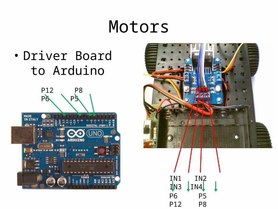
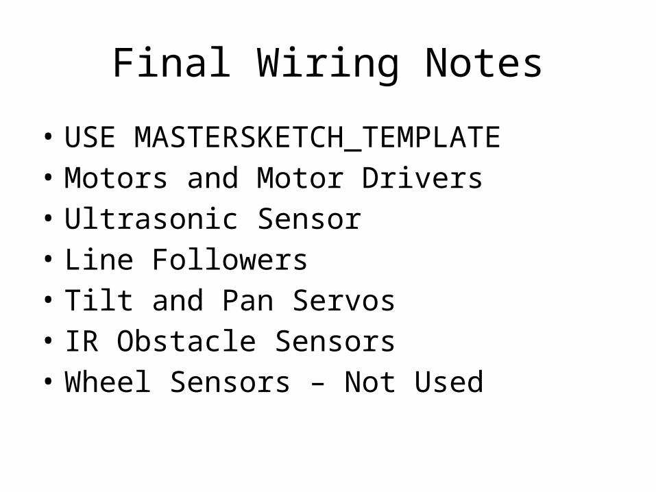
Motors
• Driver Board to Arduino
IN1 IN2 IN3 IN4
P6 P5 P12 P8
P12 P8 P6 P5
Motors
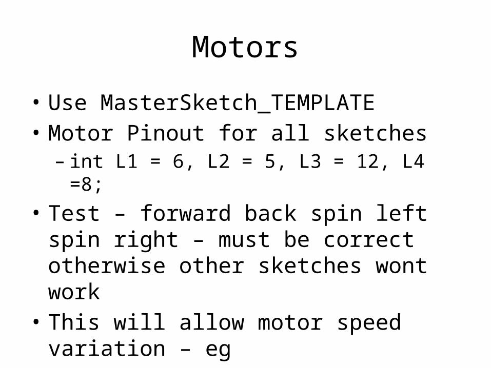
• Use MasterSketch_TEMPLATE• Motor Pinout for all sketches– int L1 = 6, L2 = 5, L3 = 12, L4 =8;
• Test – forward back spin left spin right – must be correct otherwise other sketches wont work
• This will allow motor speed variation – eg– forward(1000,150); where 150 is speed ( max 255)
UltraSonic Sensor
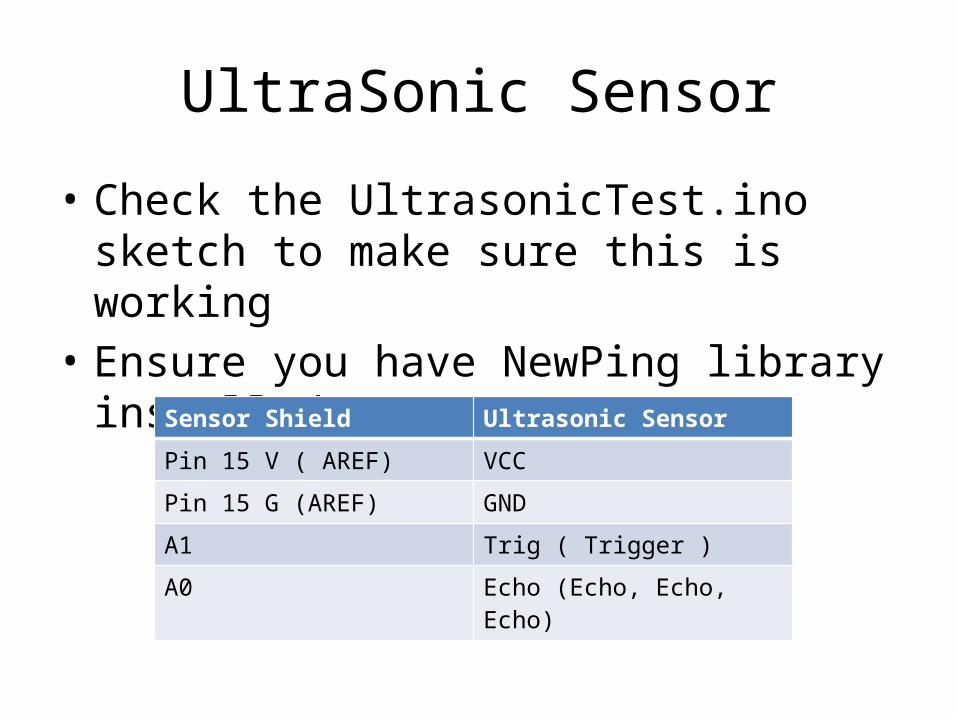
• Check the UltrasonicTest.ino sketch to make sure this is working
• Ensure you have NewPing library installed
Sensor Shield Ultrasonic Sensor
Pin 15 V ( AREF) VCC
Pin 15 G (AREF) GND
A1 Trig ( Trigger )
A0 Echo (Echo, Echo, Echo)
Line Followers
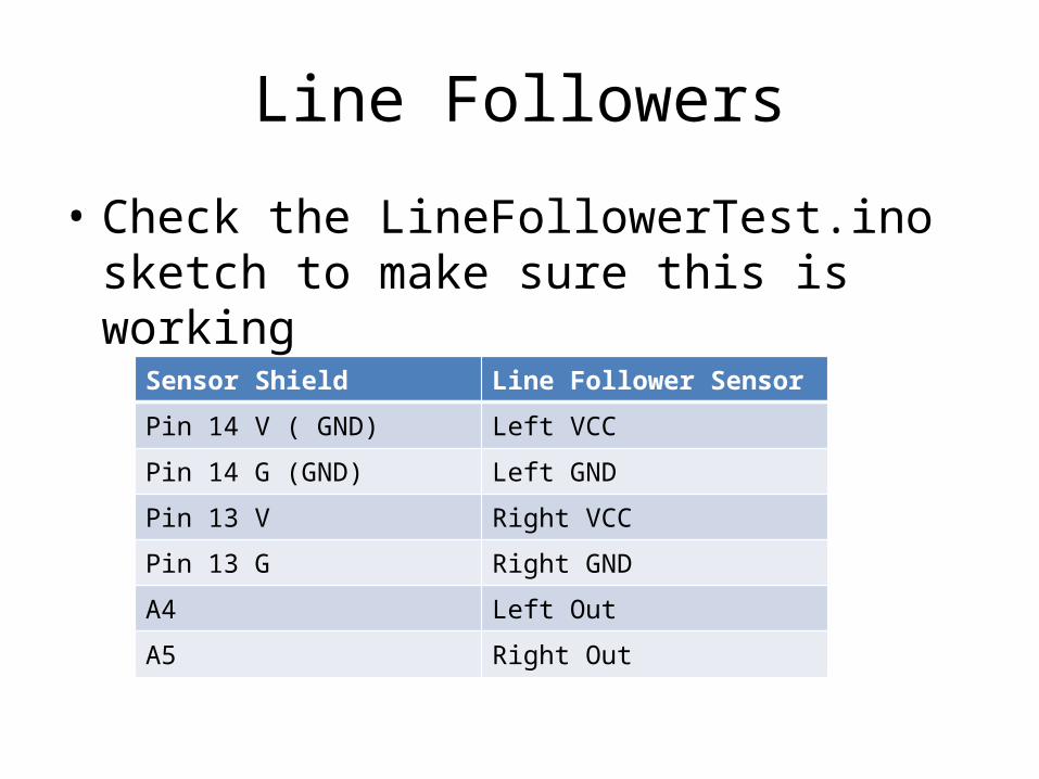
• Check the LineFollowerTest.ino sketch to make sure this is working
Sensor Shield Line Follower Sensor
Pin 14 V ( GND) Left VCC
Pin 14 G (GND) Left GND
Pin 13 V Right VCC
Pin 13 G Right GND
A4 Left Out
A5 Right Out
Line Followers
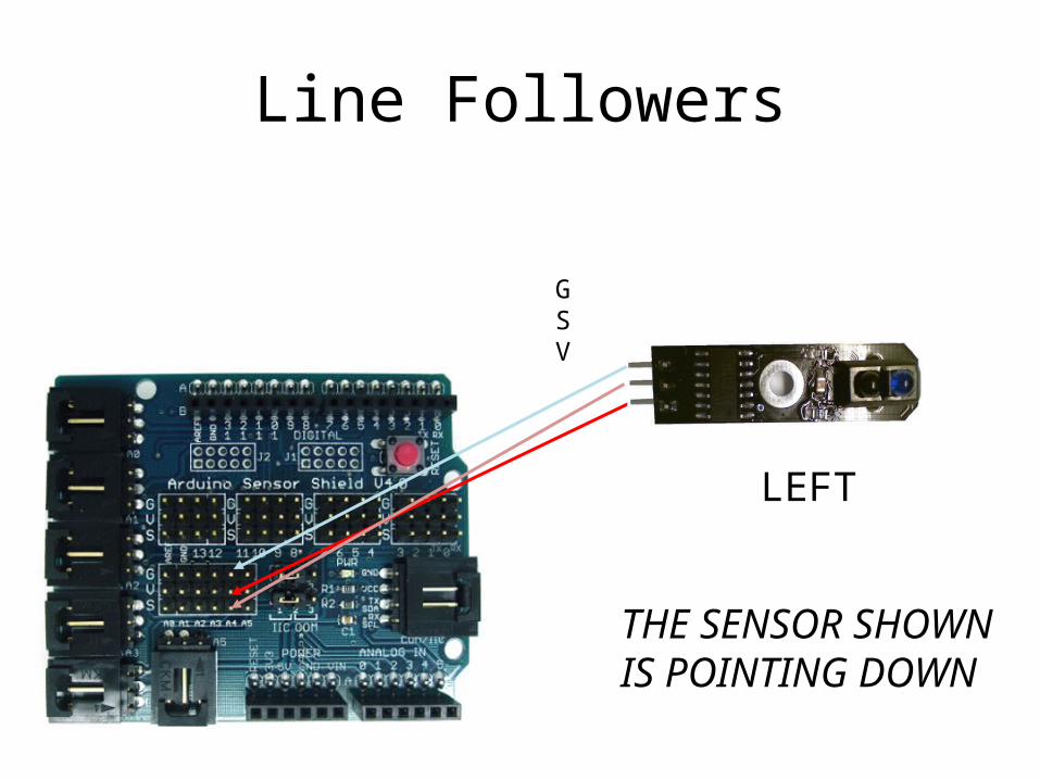
LEFT
GSV
THE SENSOR SHOWN IS POINTING DOWN
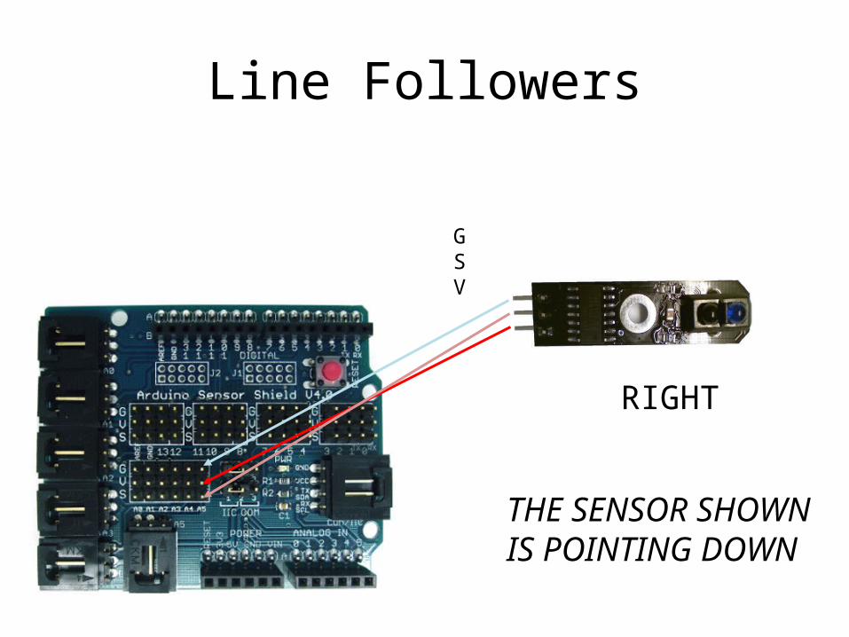
Line Followers
RIGHT
GSV
THE SENSOR SHOWN IS POINTING DOWN
Tilt and Pan
• Use the MASTERSKETCH_TEMPLATE• Maxservo value 180• Min servo value 0• Midpoint 90
Tilt and Pan
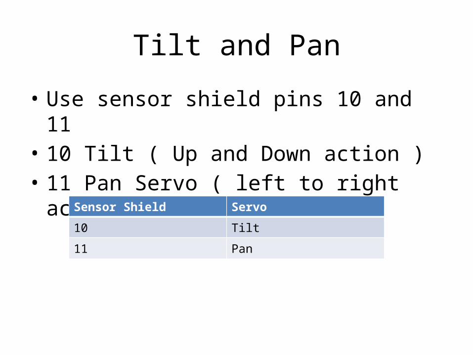
• Use sensor shield pins 10 and 11• 10 Tilt ( Up and Down action )• 11 Pan Servo ( left to right action)
Sensor Shield Servo
10 Tilt
11 Pan
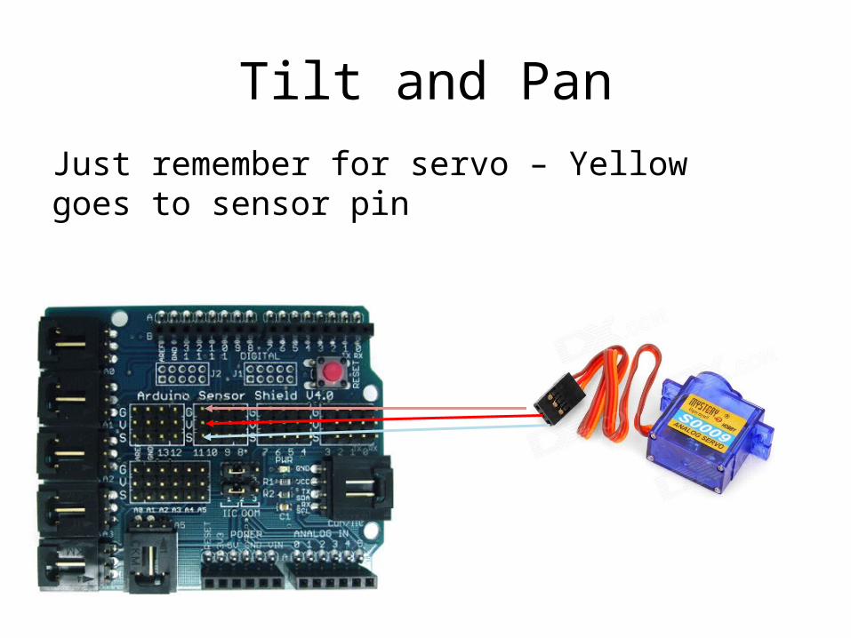
Tilt and PanJust remember for servo – Yellow goes to sensor pin
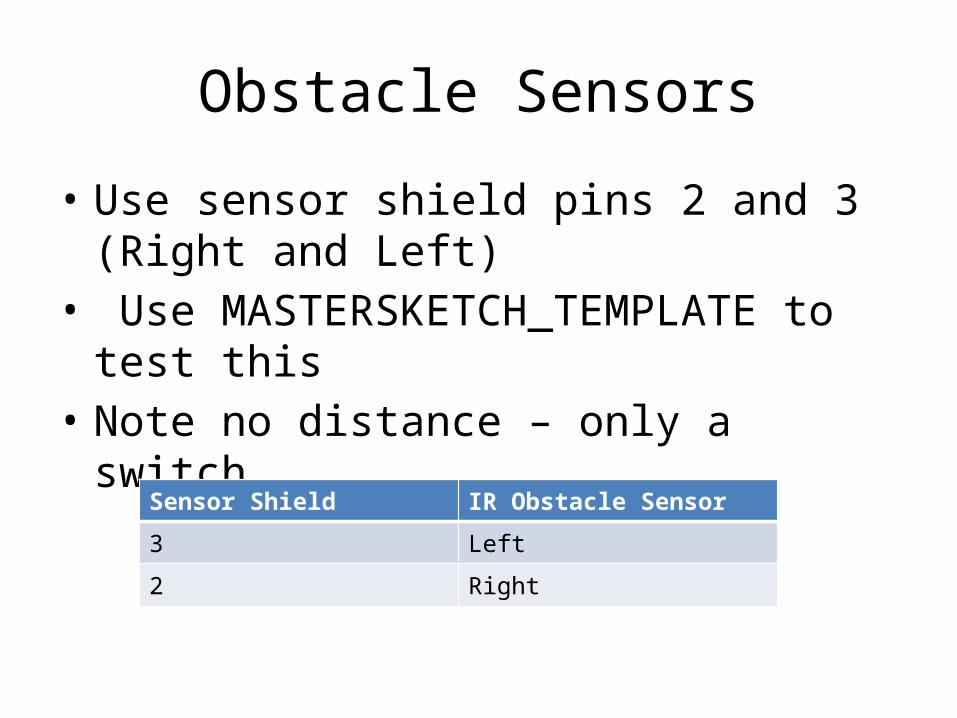
Obstacle Sensors
• Use sensor shield pins 2 and 3 (Right and Left) • Use MASTERSKETCH_TEMPLATE to test this• Note no distance – only a switch
Sensor Shield IR Obstacle Sensor
3 Left
2 Right
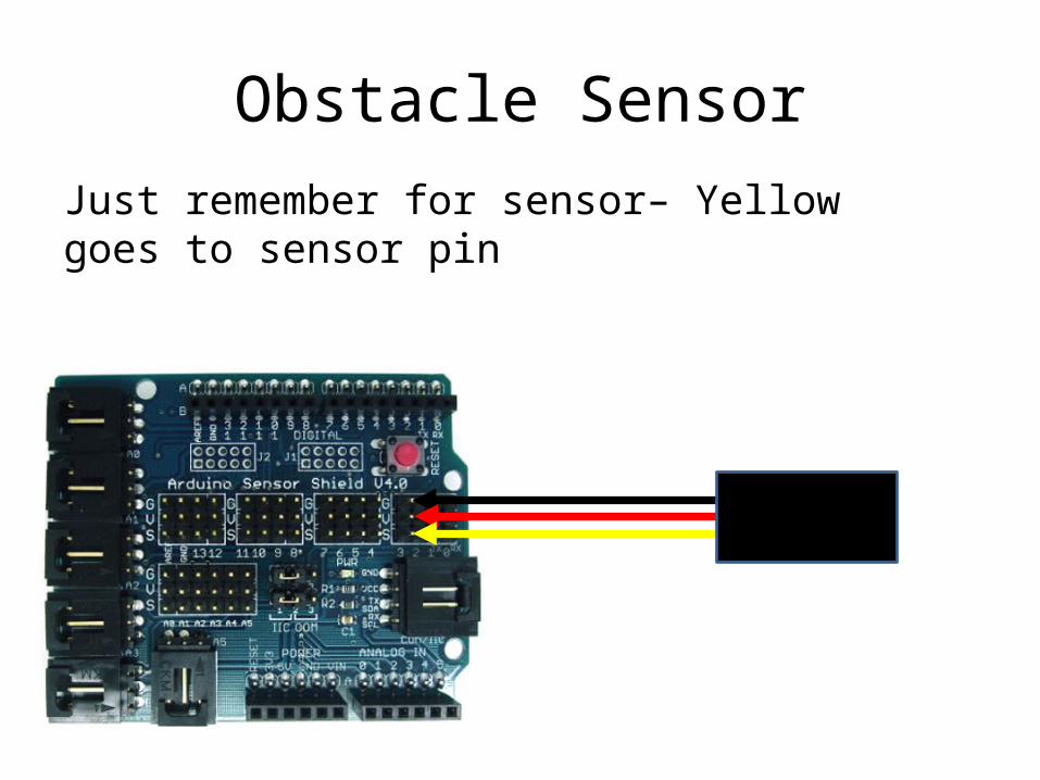
Obstacle SensorJust remember for sensor– Yellow goes to sensor pin