Embed Size (px)
Citation preview
1
FINAL VERSION FOR PUBLICATION Air Barriers vs. Vapor Barriers Roger G. Morse AIA, Stephen M. Lattanzio PE, Paul Haas CIH, Gordon A. Brandon, Brian Crowder1 ABSTRACT A great deal of attention has been paid to the determination of vapor retarder (barrier) requirements and the placement of vapor retarders, including the development of sophisticated modeling software. These efforts have given building designers and constructors the tools to evaluate and manage water vapor transport through building envelope elements. There is the potential, however, that more moisture could be admitted into an envelope component, such as a wall or attic insulation, by air infiltration than by vapor diffusion. Moisture penetration from air infiltration through cracks and gaps in construction into interstitial spaces, such as wall cavities, is less studied and less understood than vapor transport by diffusion through building materials. Air infiltration into buildings has been studied at great length for purposes of heating and cooling load calculation. Unfortunately, as currently practiced, these calculation methods take a relatively macroscopic view of building envelope elements rather than considering individual layers and specific leakage pathways through wall or roof assemblies. Air passes so readily through some low density materials, such as fiberglass insulation, that air movement caused by convection or pressure differentials can cause air exchange through the material from adjacent atmospheres. Water vapor behaves differently from the other gases that make up air, as the phase change temperatures for water are within the range often found within building assemblies. This can cause migration of water vapor in the air through thin openings, such as cracks or seams, due to the concentration gradient that results from condensation on a chilled surface. This paper reports on several situations observed in ventilated attics in South Florida, where the magnitude and location of condensation were different than predicted by available vapor diffusion calculation methods. Air infiltration calculations can account for the entry of unconditioned air through gaps in construction. However, there is an insufficient knowledge base to predict the effects of convection of air through building materials and the impact this has on moisture and condensation within assemblies. Observation of conditions that are clearly influenced by air transport of vapor, such as exposed insulation in ventilated attics, indicates that condensation is influenced by more than vapor diffusion, and that air infiltration through assemblies is an important determinant of the observed outcomes. INTRODUCTION
1 Roger G. Morse AIA is president, Morse Zehnter Associates, Troy, NY; Stephen M. Lattanzio, PE is senior engineer; Paul Haas, CIH is certified industrial hygienist; Gordon A. Brandon is senior project manager; and Brian Crowder is manager of animation services, all for Morse Zehnter Associates Troy, NY.
2
This paper describes comparisons between condensation predictions based on calculations and actual conditions observed in buildings, and serves as a step in the process to arrive at a practical methodology of estimating the total moisture dynamics of a wall, taking into consideration air infiltration and circulation as well as vapor diffusion. The issue is illustrated by consideration of actual situations found during investigations of moisture problems in building envelopes. Instances have been found where condensation damage occurred in locations other than those predicted by calculation of water vapor transport by diffusion. Other instances have been found where moisture damage did not occur at all despite the presence of misplaced vapor retarders. Conditions found in two similar Florida houses illustrate the effect of air infiltration and diffusion on condensation in building envelope assemblies. Both houses were investigated as the result of reported moisture and mold problems. Both had ventilated attics and insulated wood stud and drywall partitions separating air conditioned space from the attic. Both houses had misplaced vapor retarders with the “kraft” paper facing of the insulation located toward the conditioned space rather than toward the hot and humid attic space. In one house, fiberglass insulation was open to a ventilated attic and as such was directly influenced by air circulation through the insulation. Moisture problems and mold growth within the wall assembly were observed in this house. Condensation within the wall assembly was predicted by diffusion calculations, but the locations of condensation that actually occurred differed from those predicted by the calculations. In the second house, the construction was similar except that a plywood panel had been installed between the insulation and the ventilated attic, thus reducing water vapor transmission into the assembly and also preventing air circulation through the insulation. In this house, no condensation problems were observed within the wall assembly, although condensation at the misplaced vapor retarder was predicted by calculation. The insulation in both houses consisted of fiberglass batt insulation adhered to a “kraft” paper facing. As with most modern insulation products, this “kraft” facing is not a simple layer of kraft paper. Rather, it is a complex laminated assembly of kraft paper and polyethylene that is relatively water resistant and that provides a perm rating of 1.0, and, as such, qualifies as a vapor retarder as required by many building codes. In both houses, rooms on the second floor were surrounded on all but one exterior wall by unconditioned and uninsulated attic spaces that were well ventilated with soffit vents in accordance with the Florida Building Code. In both instances, these attics were hot humid spaces with environmental conditions strongly linked to outdoor conditions. Due to solar loading on the roofs, air temperatures in these spaces generally exceed outdoor temperatures, so relative humidity in the attics is generally less than that outdoors and is inversely proportional to the temperature difference. TEST HOUSE 1 Fiberglass insulation was exposed without any cover to the attic space in the first house investigated. This is a common configuration in Florida house construction, as is the
3
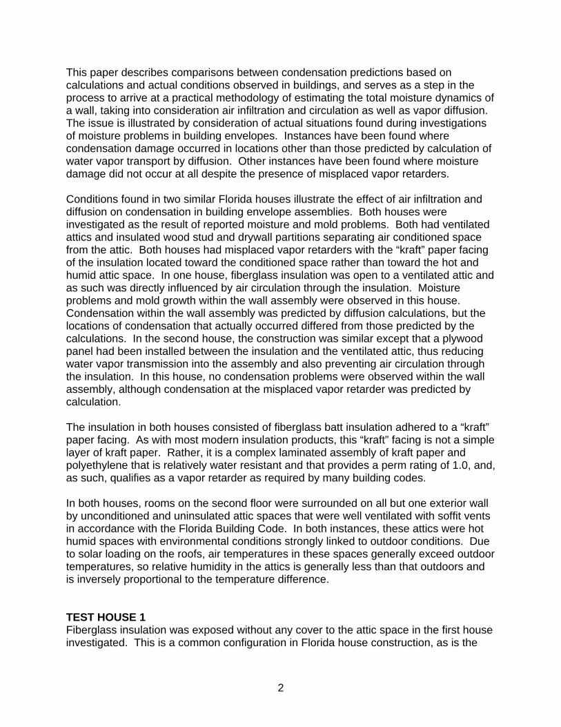
misplaced vapor retarder in situations where insulation with a “kraft” paper face is used. Most of the interior space in this house was painted, but a wainscot of plastic coated wall paper had been installed on the lower part of the walls backing up to the unconditioned attic. Investigation of the wall was in response to complaints about mold growth behind plastic coated wall paper installed as a wainscot in a children’s play room. Figure 1 – Wall with insulation open to attic
½" GYP. BOARD
2×4 STUD(TYP.)
KRAFT PAPER FACEDFIBERGLASS BATT
INSULATION
VENTILATEDATTIC
AIR CONDITIONEDROOM
PLASTIC COVEREDWALL PAPER
WAINSCOT
CHAIR RAIL
The construction illustrated in Figure 1 had mold growth behind plastic coated wall paper. The room was framed out within an unconditioned and ventilated attic with 2x4 wood studs that were covered on the room side with ½” gypsum wall board. Fiberglass batt insulation with a “kraft” face was installed as friction batting between the studs with the “kraft” facing toward the inside. This left the back of the insulation open to the attic space, which is ventilated to the hot humid Florida atmosphere, making the “kraft” facing a misplaced vapor retarder inside of the insulation (toward the interior). Manufacturer’s data indicates that the “kraft” facing is a laminated construction with a perm rating of approximately 1.0 as measured by ASTM Standard E 96 (ASTM International 1996) using the dry cup method and as such qualifies as a vapor retarder. Application of Analytical Tools Analytical tools, ranging from simplistic to sophisticated, have been developed for determining the behavior of water vapor passing through building materials as a gas.
4
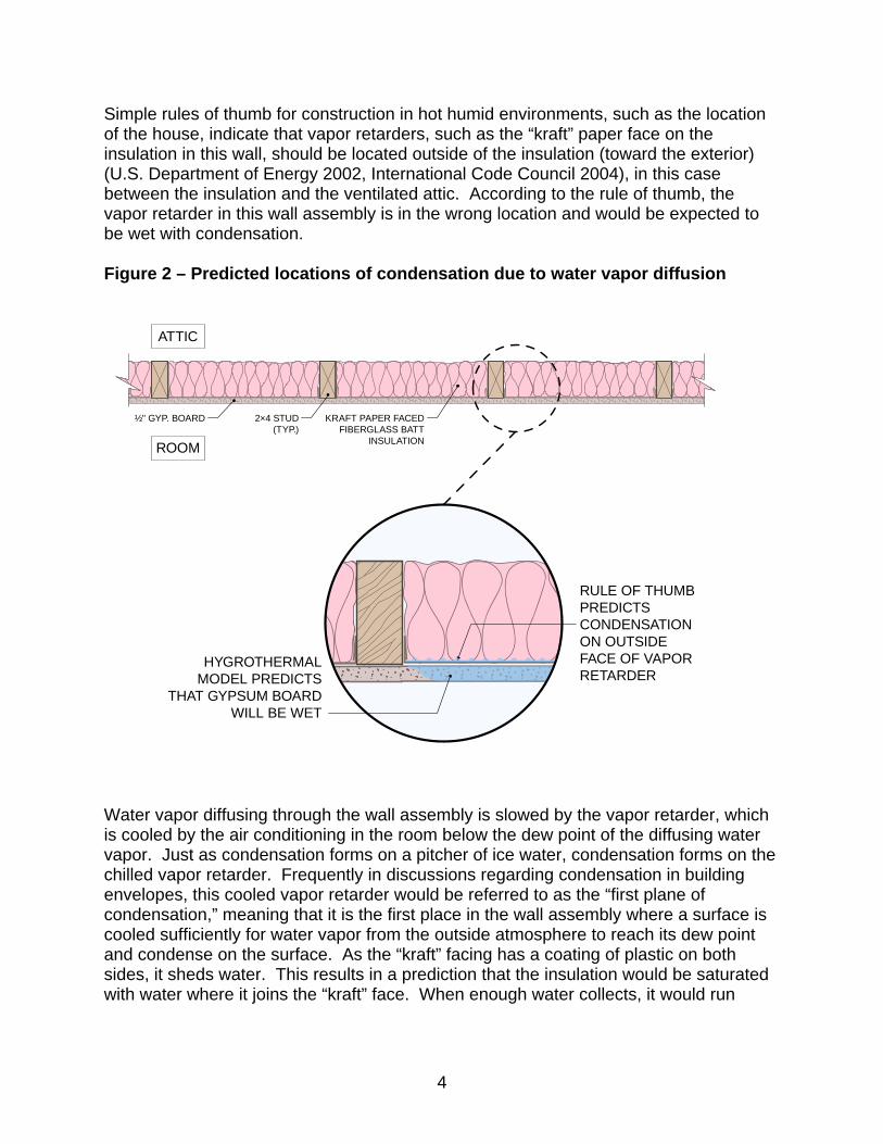
Simple rules of thumb for construction in hot humid environments, such as the location of the house, indicate that vapor retarders, such as the “kraft” paper face on the insulation in this wall, should be located outside of the insulation (toward the exterior) (U.S. Department of Energy 2002, International Code Council 2004), in this case between the insulation and the ventilated attic. According to the rule of thumb, the vapor retarder in this wall assembly is in the wrong location and would be expected to be wet with condensation. Figure 2 – Predicted locations of condensation due to water vapor diffusion
RULE OF THUMBPREDICTSCONDENSATIONON OUTSIDEFACE OF VAPORRETARDER
HYGROTHERMALMODEL PREDICTS
THAT GYPSUM BOARDWILL BE WET
½" GYP. BOARD 2×4 STUD(TYP.)
KRAFT PAPER FACEDFIBERGLASS BATT
INSULATION
ATTIC
ROOM
Water vapor diffusing through the wall assembly is slowed by the vapor retarder, which is cooled by the air conditioning in the room below the dew point of the diffusing water vapor. Just as condensation forms on a pitcher of ice water, condensation forms on the chilled vapor retarder. Frequently in discussions regarding condensation in building envelopes, this cooled vapor retarder would be referred to as the “first plane of condensation,” meaning that it is the first place in the wall assembly where a surface is cooled sufficiently for water vapor from the outside atmosphere to reach its dew point and condense on the surface. As the “kraft” facing has a coating of plastic on both sides, it sheds water. This results in a prediction that the insulation would be saturated with water where it joins the “kraft” face. When enough water collects, it would run
5
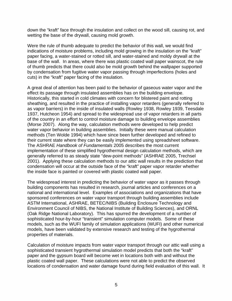
down the “kraft” face through the insulation and collect on the wood sill, causing rot, and wetting the base of the drywall, causing mold growth. Were the rule of thumb adequate to predict the behavior of this wall, we would find indications of moisture problems, including mold growing in the insulation on the “kraft” paper facing, a water-stained or rotted sill, and water-stained and moldy drywall at the base of the wall. In areas, where there was plastic coated wall paper wainscot, the rule of thumb predicts that there could also be mold growth behind the wallpaper supported by condensation from fugitive water vapor passing through imperfections (holes and cuts) in the “kraft” paper facing of the insulation. A great deal of attention has been paid to the behavior of gaseous water vapor and the effect its passage through insulated assemblies has on the building envelope. Historically, this started in cold climates with concern for blistered paint and rotting sheathing, and resulted in the practice of installing vapor retarders (generally referred to as vapor barriers) in the inside of insulated walls (Rowley 1938, Rowley 1939, Teesdale 1937, Hutcheon 1954) and spread to the widespread use of vapor retarders in all parts of the country in an effort to control moisture damage to building envelope assemblies (Morse 2007). Along the way, calculation methods were developed to help predict water vapor behavior in building assemblies. Initially these were manual calculation methods (Ten Wolde 1994) which have since been further developed and refined to their current state where they can be easily implemented using spreadsheet software. The ASHRAE Handbook of Fundamentals 2005 describes the most current implementation of these simplified hygrothermal design calculation methods, which are generally referred to as steady state “dew-point methods” (ASHRAE 2005, Trechsel 2001). Applying these calculation methods to our attic wall results in the prediction that condensation will occur at the outside face of the “kraft” paper vapor retarder whether the inside face is painted or covered with plastic coated wall paper. The widespread interest in predicting the behavior of water vapor as it passes through building components has resulted in research, journal articles and conferences on a national and international level. Examples of associations and organizations that have sponsored conferences on water vapor transport through building assemblies include ASTM International, ASHRAE, BETEC/NIBS (Building Enclosure Technology and Environment Council of NIBS, the National Institute of Building Sciences), and ORNL (Oak Ridge National Laboratory). This has spurred the development of a number of sophisticated hour-by-hour “transient” simulation computer models. Some of these models, such as the WUFI family of simulation applications (WUFI) and other numerical models, have been validated by extensive research and testing of the hygrothermal properties of materials. Calculation of moisture impacts from water vapor transport through our attic wall using a sophisticated transient hygrothermal simulation model predicts that both the “kraft” paper and the gypsum board will become wet in locations both with and without the plastic coated wall paper. These calculations were not able to predict the observed locations of condensation and water damage found during field evaluation of this wall. It
6
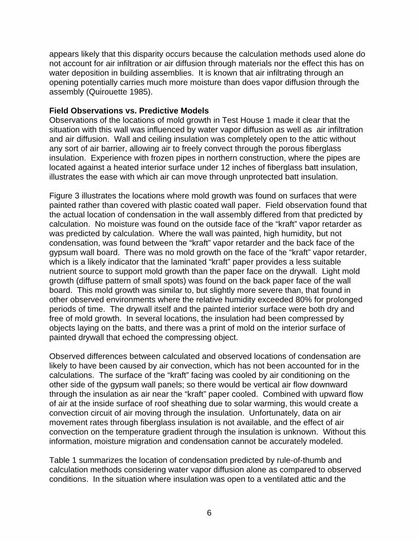
appears likely that this disparity occurs because the calculation methods used alone do not account for air infiltration or air diffusion through materials nor the effect this has on water deposition in building assemblies. It is known that air infiltrating through an opening potentially carries much more moisture than does vapor diffusion through the assembly (Quirouette 1985). Field Observations vs. Predictive Models Observations of the locations of mold growth in Test House 1 made it clear that the situation with this wall was influenced by water vapor diffusion as well as air infiltration and air diffusion. Wall and ceiling insulation was completely open to the attic without any sort of air barrier, allowing air to freely convect through the porous fiberglass insulation. Experience with frozen pipes in northern construction, where the pipes are located against a heated interior surface under 12 inches of fiberglass batt insulation, illustrates the ease with which air can move through unprotected batt insulation. Figure 3 illustrates the locations where mold growth was found on surfaces that were painted rather than covered with plastic coated wall paper. Field observation found that the actual location of condensation in the wall assembly differed from that predicted by calculation. No moisture was found on the outside face of the “kraft” vapor retarder as was predicted by calculation. Where the wall was painted, high humidity, but not condensation, was found between the “kraft” vapor retarder and the back face of the gypsum wall board. There was no mold growth on the face of the “kraft” vapor retarder, which is a likely indicator that the laminated “kraft” paper provides a less suitable nutrient source to support mold growth than the paper face on the drywall. Light mold growth (diffuse pattern of small spots) was found on the back paper face of the wall board. This mold growth was similar to, but slightly more severe than, that found in other observed environments where the relative humidity exceeded 80% for prolonged periods of time. The drywall itself and the painted interior surface were both dry and free of mold growth. In several locations, the insulation had been compressed by objects laying on the batts, and there was a print of mold on the interior surface of painted drywall that echoed the compressing object. Observed differences between calculated and observed locations of condensation are likely to have been caused by air convection, which has not been accounted for in the calculations. The surface of the “kraft” facing was cooled by air conditioning on the other side of the gypsum wall panels; so there would be vertical air flow downward through the insulation as air near the “kraft” paper cooled. Combined with upward flow of air at the inside surface of roof sheathing due to solar warming, this would create a convection circuit of air moving through the insulation. Unfortunately, data on air movement rates through fiberglass insulation is not available, and the effect of air convection on the temperature gradient through the insulation is unknown. Without this information, moisture migration and condensation cannot be accurately modeled. Table 1 summarizes the location of condensation predicted by rule-of-thumb and calculation methods considering water vapor diffusion alone as compared to observed conditions. In the situation where insulation was open to a ventilated attic and the
7
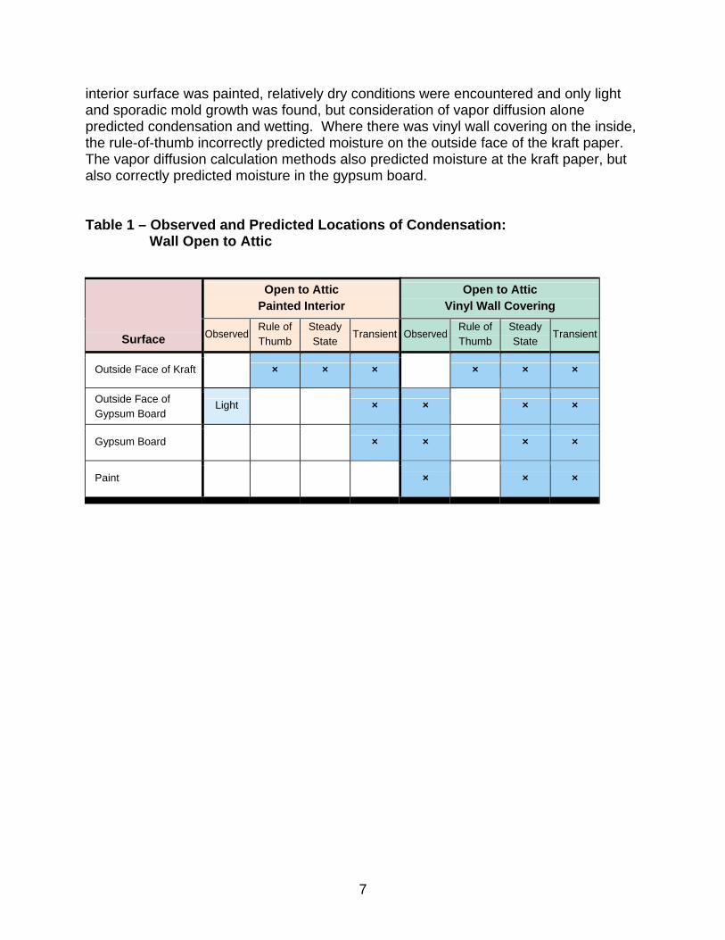
interior surface was painted, relatively dry conditions were encountered and only light and sporadic mold growth was found, but consideration of vapor diffusion alone predicted condensation and wetting. Where there was vinyl wall covering on the inside, the rule-of-thumb incorrectly predicted moisture on the outside face of the kraft paper. The vapor diffusion calculation methods also predicted moisture at the kraft paper, but also correctly predicted moisture in the gypsum board. Table 1 – Observed and Predicted Locations of Condensation:
Wall Open to Attic
Open to Attic
Painted Interior Open to Attic
Vinyl Wall Covering
Surface Observed Rule of Thumb
Steady State
Transient ObservedRule of Thumb
Steady State
Transient
Outside Face of Kraft × × × × × ×
Outside Face of Gypsum Board
Light × × × ×
Gypsum Board × × × ×
Paint × × ×
8
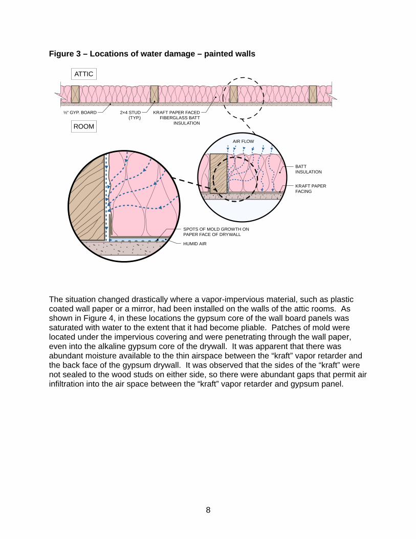
Figure 3 – Locations of water damage – painted walls
½" GYP. BOARD 2×4 STUD(TYP.)
KRAFT PAPER FACEDFIBERGLASS BATT
INSULATION
ATTIC
ROOM
AIR FLOW
BATTINSULATION
KRAFT PAPERFACING
SPOTS OF MOLD GROWTH ONPAPER FACE OF DRYWALL
HUMID AIR
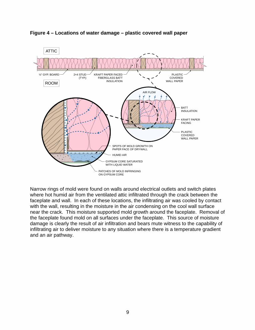
The situation changed drastically where a vapor-impervious material, such as plastic coated wall paper or a mirror, had been installed on the walls of the attic rooms. As shown in Figure 4, in these locations the gypsum core of the wall board panels was saturated with water to the extent that it had become pliable. Patches of mold were located under the impervious covering and were penetrating through the wall paper, even into the alkaline gypsum core of the drywall. It was apparent that there was abundant moisture available to the thin airspace between the “kraft” vapor retarder and the back face of the gypsum drywall. It was observed that the sides of the “kraft” were not sealed to the wood studs on either side, so there were abundant gaps that permit air infiltration into the air space between the “kraft” vapor retarder and gypsum panel.
9
Figure 4 – Locations of water damage – plastic covered wall paper
½" GYP. BOARD 2×4 STUD(TYP.)
KRAFT PAPER FACEDFIBERGLASS BATT
INSULATION
ATTIC
ROOM
AIR FLOW
BATTINSULATION
KRAFT PAPERFACING
SPOTS OF MOLD GROWTH ONPAPER FACE OF DRYWALL
HUMID AIR
PATCHES OF MOLD INFRINGINGON GYPSUM CORE
GYPSUM CORE SATURATEDWITH LIQUID WATER
PLASTICCOVERED
WALL PAPER
PLASTICCOVEREDWALL PAPER
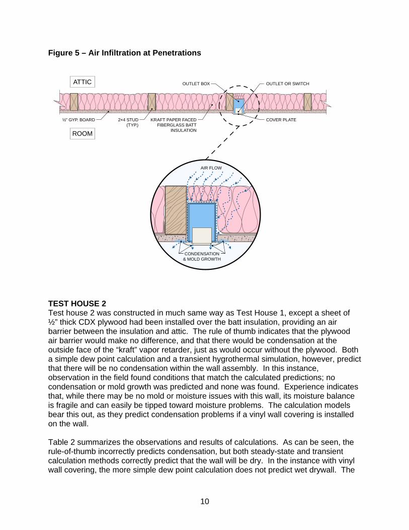
Narrow rings of mold were found on walls around electrical outlets and switch plates where hot humid air from the ventilated attic infiltrated through the crack between the faceplate and wall. In each of these locations, the infiltrating air was cooled by contact with the wall, resulting in the moisture in the air condensing on the cool wall surface near the crack. This moisture supported mold growth around the faceplate. Removal of the faceplate found mold on all surfaces under the faceplate. This source of moisture damage is clearly the result of air infiltration and bears mute witness to the capability of infiltrating air to deliver moisture to any situation where there is a temperature gradient and an air pathway.
10
Figure 5 – Air Infiltration at Penetrations
AIR FLOW
CONDENSATION& MOLD GROWTH
½" GYP. BOARD 2×4 STUD(TYP.)
KRAFT PAPER FACEDFIBERGLASS BATT
INSULATION
ATTIC
ROOM
OUTLET BOX
COVER PLATE
OUTLET OR SWITCH
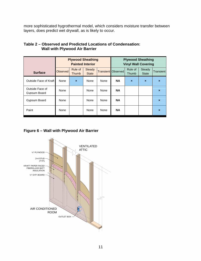
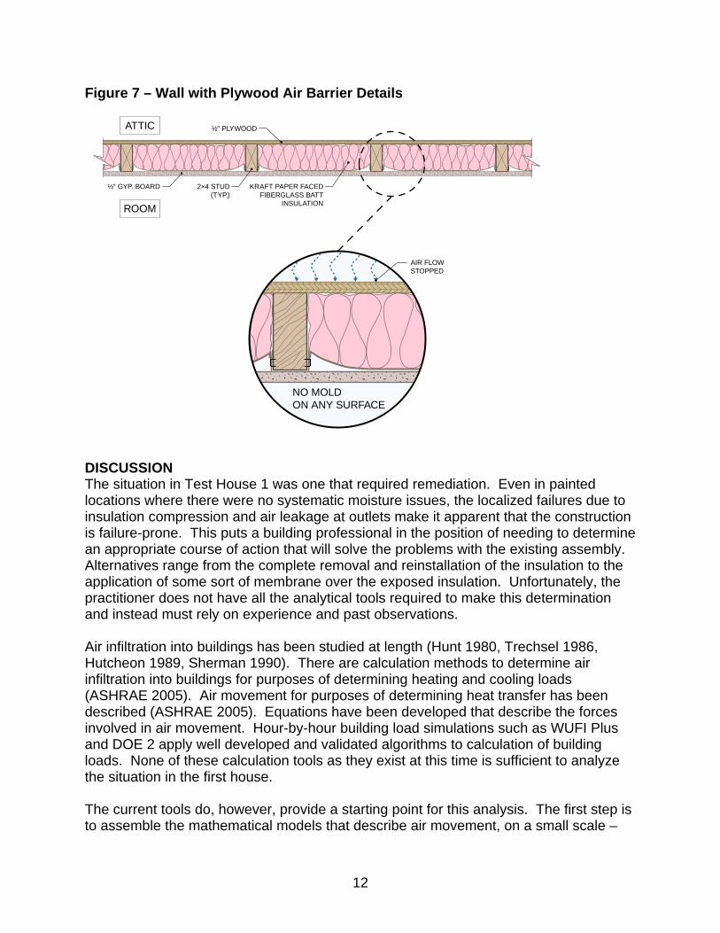
TEST HOUSE 2 Test house 2 was constructed in much same way as Test House 1, except a sheet of ½” thick CDX plywood had been installed over the batt insulation, providing an air barrier between the insulation and attic. The rule of thumb indicates that the plywood air barrier would make no difference, and that there would be condensation at the outside face of the “kraft” vapor retarder, just as would occur without the plywood. Both a simple dew point calculation and a transient hygrothermal simulation, however, predict that there will be no condensation within the wall assembly. In this instance, observation in the field found conditions that match the calculated predictions; no condensation or mold growth was predicted and none was found. Experience indicates that, while there may be no mold or moisture issues with this wall, its moisture balance is fragile and can easily be tipped toward moisture problems. The calculation models bear this out, as they predict condensation problems if a vinyl wall covering is installed on the wall. Table 2 summarizes the observations and results of calculations. As can be seen, the rule-of-thumb incorrectly predicts condensation, but both steady-state and transient calculation methods correctly predict that the wall will be dry. In the instance with vinyl wall covering, the more simple dew point calculation does not predict wet drywall. The
11
more sophisticated hygrothermal model, which considers moisture transfer between layers, does predict wet drywall, as is likely to occur. Table 2 – Observed and Predicted Locations of Condensation:
Wall with Plywood Air Barrier
Figure 6 – Wall with Plywood Air Barrier
½" GYP. BOARD
2×4 STUD(TYP.)
KRAFT PAPER FACEDFIBERGLASS BATT
INSULATION
VENTILATEDATTIC
AIR CONDITIONEDROOM
OUTLET BOX
½" PLYWOOD
Plywood Sheathing Painted Interior
Plywood Sheathing Vinyl Wall Covering
Surface Observed Rule of Thumb
Steady State
Transient ObservedRule of Thumb
Steady State
Transient
Outside Face of Kraft None × None None NA × × ×
Outside Face of Gypsum Board
None None None NA ×
Gypsum Board None None None NA ×
Paint None None None NA ×
12
Figure 7 – Wall with Plywood Air Barrier Details
½" GYP. BOARD 2×4 STUD(TYP.)
KRAFT PAPER FACEDFIBERGLASS BATT
INSULATION
ATTIC
ROOM
½" PLYWOOD
NO MOLDON ANY SURFACE
AIR FLOWSTOPPED
DISCUSSION The situation in Test House 1 was one that required remediation. Even in painted locations where there were no systematic moisture issues, the localized failures due to insulation compression and air leakage at outlets make it apparent that the construction is failure-prone. This puts a building professional in the position of needing to determine an appropriate course of action that will solve the problems with the existing assembly. Alternatives range from the complete removal and reinstallation of the insulation to the application of some sort of membrane over the exposed insulation. Unfortunately, the practitioner does not have all the analytical tools required to make this determination and instead must rely on experience and past observations. Air infiltration into buildings has been studied at length (Hunt 1980, Trechsel 1986, Hutcheon 1989, Sherman 1990). There are calculation methods to determine air infiltration into buildings for purposes of determining heating and cooling loads (ASHRAE 2005). Air movement for purposes of determining heat transfer has been described (ASHRAE 2005). Equations have been developed that describe the forces involved in air movement. Hour-by-hour building load simulations such as WUFI Plus and DOE 2 apply well developed and validated algorithms to calculation of building loads. None of these calculation tools as they exist at this time is sufficient to analyze the situation in the first house. The current tools do, however, provide a starting point for this analysis. The first step is to assemble the mathematical models that describe air movement, on a small scale –
13
within building assemblies, together with the calculation engine of a well validated hour-by-hour building load simulation program, to arrive at a model to determine airflow through building envelopes. In conjunction with that, basic research regarding air diffusion through materials, particularly porous materials such as insulation, needs to be conducted. This would logically be followed up by validation testing of a range of assemblies. RECOMMENDATIONS Conditions such as those in Test House 1, in which a building assembly is strongly influenced by ventilation, infiltration, or direct exposure to the air, requires evaluation that considers not only water vapor diffusion, but also air infiltration, convection, and water vapor diffusion through leak paths in order to correctly characterize the potential for condensation within the assembly. Well validated, tested and user-friendly calculation methods exist for vapor diffusion in the form of transient simulation programs. There are no such well developed calculation methods for air infiltration, convection, and water vapor diffusion into and through imperfections in the building envelope. That being the case, until such time that the necessary calculation methods are developed, the practitioner must rely on informed experience gained from inspection of successful (and unsuccessful) building assemblies. Where information from past practices is not available, assemblies that are strongly influenced by ventilation, air infiltration, convection, and air diffusion should be avoided by careful design and installation of an air barrier.
14
REFERENCES ASHRAE. 2005. Handbook of Fundamentals. American Society of Heating, Refrigerating and Air-Conditioning Engineers, Inc. ASTM International. 1996. ASTM E 96/E 96M-05, Standard Test Methods for Water Vapor Transmission of Materials. ASTM International, West Conshohocken, PA. Hunt, C.M., J.C. King, and H.R. Trechsel, Eds. 1980. Building Air Change Rate and Infiltration Measurements, ASTM STP 719. American Society for Testing and Materials, Philadelphia, PA.
Hutcheon, N.B. 1989. Forty Years of Vapor Barriers. Water Vapor Transmission Through Building Materials and Systems: Mechanisms and Measurement, ASTM STP 1039, H.R. Trechsel and M. Bomberg, Eds., American Society for Testing and Materials, Philadelphia, PA, pp. 5-7. Hutcheon, N. 1954. Report on Quonset Building, Saskatchewan Hospital, North Battleford, typewritten report to NRC (Canada) (1950); Control of Water Vapour in Dwellings, Technical Paper no. 19 of the Division of Building Research, National Research Council of Canada, NRC No. 3343.
International Code Council. 2004. 2004 Florida Building Code, Building. Morse, R.G. and National Institute of Building Sciences. 2005. Building Envelope Guide, Indoor Air Quality and Mold Prevention of the Building Envelope in the National Institute of Building Sciences (NIBS) Whole Building Design Guide. Morse, R.G. 2007. Vernacular Architecture: Differences for Moisture Design by Hygrothermal Regions. Presented at the November 1, 2007 ASTM Symposium on “Up Against the Wall”: An Examination of Building Envelope Interface. ASTM International. Quirouette, R.L. 1985. The Difference Between A Vapor Barrier and an Air Barrier; Building Practice Note 54, Division of Building Research, National Research Council of Canada, ISSN 0701-5216, Ottawa, Ontario, Canada. Rowley, F., Algren, A., and Lund, C. 1938. Condensation within walls. ASHVE Transactions, 44 No. 1077. Rowley, F., Algren, A., and Lund, C. 1939. Condensation of moisture and its relation to building construction and operation. ASHVE Transactions, 45 No. 1115. Sherman, M.H., Ed. 1990. Air Change Rate and Airtightness in Buildings, ASTM STP 1067. American Society for Testing and Materials, Philadelphia, PA.
15
Teesdale, T. October 1937. Condensation in Walls and Attics. US Forest Products Bulletin. Ten Wolde, A. 1994. Design Tools. Chapter 11 in Moisture control in buildings, ASTM Manual MNL 18. American Society for Testing and Materials, West Conshohocken, PA. Trechsel, Heinz R., Ed. 2001. Moisture Analysis and Condensation Control in Building Envelopes. ASTM Manual MNL 40. American Society for Testing and Materials, West Conshohocken, PA. Trechsel, H.R. and P.L. Lagus, Eds. 1986. Measured Air Leakage of Buildings, ASTM STP 904. American Society for Testing and Materials, Philadelphia, PA. U.S. Department of Energy, Building Science Corporation, and the Energy & Environmental Building Association. 2002. Builder’s Guide, Hot Humid Climates. Building Science Corporation. WUFI (Wärme und Feuchte Instationär) Version 4.1, and WUFI 2D, WUFI Plus, WUFI Mold. Fraunhofer Institute and Oak Ridge National Laboratory.