Embed Size (px)
Citation preview
Quallion LLC Project Title:
DOE Anti-Idling
Author:
Keith Kelly
Create Date January 28, 2010
Anti-Idling Battery for Truck Applications
Final Scientific / Technical Report for
Assistance Agreement
DE-EE0001038
December 30, 2011
Prepared by: Keith Kelly

DISCLAIMER
This report was prepared as an account of work sponsored by an agency of the United States Government. Neither the United States Government nor any agency thereof, nor any of their employees, makes any warranty, express or implied, or assumes any legal liability or responsibility for the accuracy, completeness, or usefulness of any information, apparatus, product, or process disclosed, or represents that its use would not infringe privately owned rights. Reference herein to any specific commercial product, process, or service by trade name, trademark, manufacturer, or otherwise does not necessarily constitute or imply its endorsement, recommendation, or favoring by the United States Government or any agency thereof. The views and opinions of authors expressed herein do not necessarily state or reflect those of the United States Government or any agency thereof.
Page 2 of 18
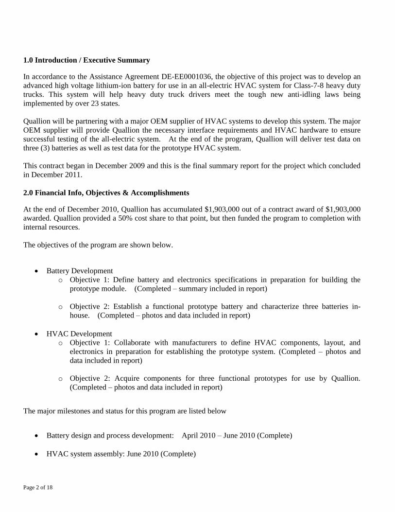
1.0 Introduction / Executive Summary
In accordance to the Assistance Agreement DE-EE0001036, the objective of this project was to develop an
advanced high voltage lithium-ion battery for use in an all-electric HVAC system for Class-7-8 heavy duty
trucks. This system will help heavy duty truck drivers meet the tough new anti-idling laws being
implemented by over 23 states.
Quallion will be partnering with a major OEM supplier of HVAC systems to develop this system. The major
OEM supplier will provide Quallion the necessary interface requirements and HVAC hardware to ensure
successful testing of the all-electric system. At the end of the program, Quallion will deliver test data on
three (3) batteries as well as test data for the prototype HVAC system.
This contract began in December 2009 and this is the final summary report for the project which concluded
in December 2011.
2.0 Financial Info, Objectives & Accomplishments
At the end of December 2010, Quallion has accumulated $1,903,000 out of a contract award of $1,903,000
awarded. Quallion provided a 50% cost share to that point, but then funded the program to completion with
internal resources.
The objectives of the program are shown below.
Battery Development
o Objective 1: Define battery and electronics specifications in preparation for building the
prototype module. (Completed – summary included in report)
o Objective 2: Establish a functional prototype battery and characterize three batteries in-
house. (Completed – photos and data included in report)
HVAC Development
o Objective 1: Collaborate with manufacturers to define HVAC components, layout, and
electronics in preparation for establishing the prototype system. (Completed – photos and
data included in report)
o Objective 2: Acquire components for three functional prototypes for use by Quallion.
(Completed – photos and data included in report)
The major milestones and status for this program are listed below
Battery design and process development: April 2010 – June 2010 (Complete)
HVAC system assembly: June 2010 (Complete)
Page 3 of 18
Testing: September to October 2010 (Complete for three batteries)
Final report: December 2011 (This document)
Prototype Battery data to DOE March 2011 (Complete – included in report)
3.0 Summary of Work Performed
In December 2009, Quallion held a kick-off meeting with the DOE and discussed our plan forward, the
system design with the HVAC OEM, program funding and major tasks. In addition a preliminary concept
drawing for the Quallion high voltage battery was developed and sent to the HVAC OEM.
Since the initial kick-off meeting, Quallion has acquired a Class 8 truck for testing, completed a battery
design and assembly process, developed an electrical system design, developed and programmed a test plan,
and established where the battery is to be placed on the system. Further, we acquired the first prototype
HVAC components, integrated them with the first prototype battery and installed the components on the
truck. Quallion and the HVAC supplier also performed testing of the prototype system as installed on the
truck and of all three batteries. Details regarding these developments are in the sections that follow:
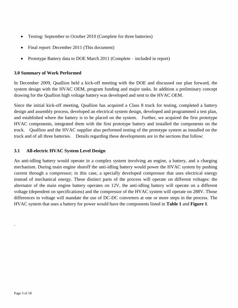
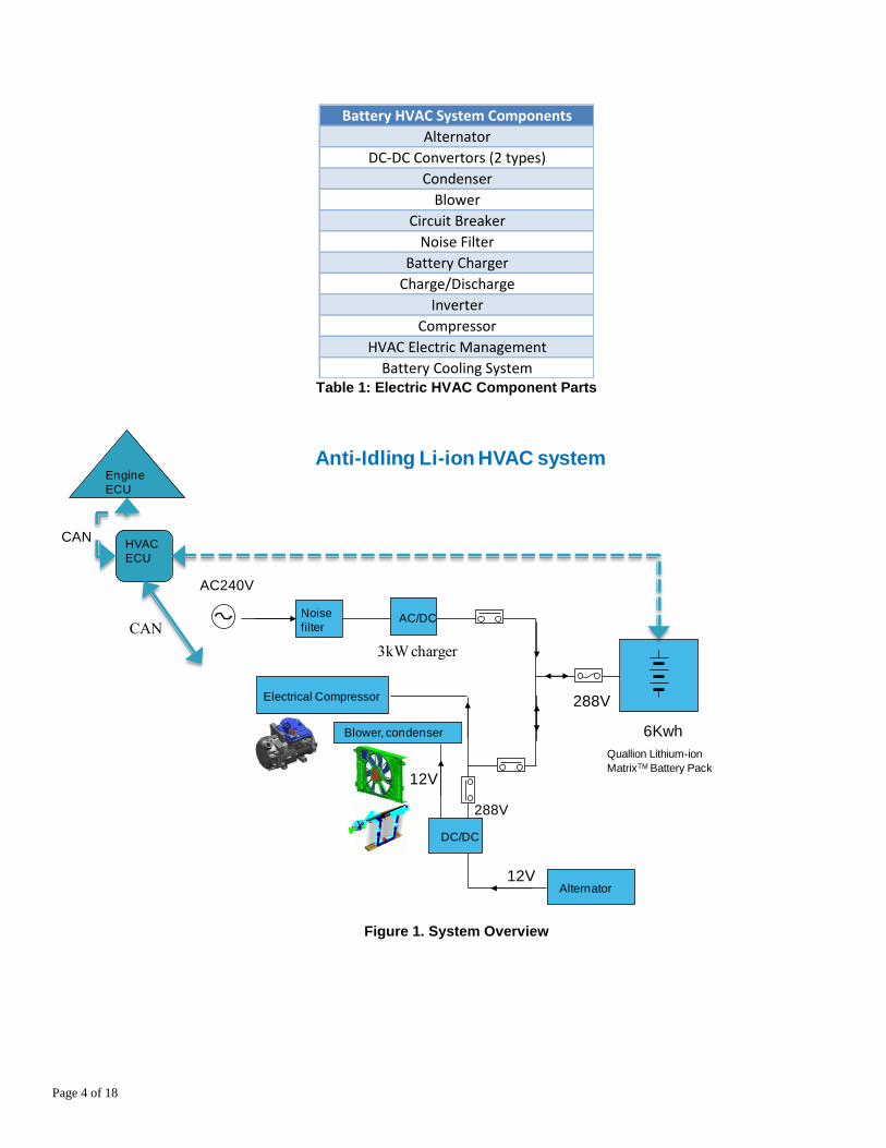
3.1 All-electric HVAC System Level Design
An anti-idling battery would operate in a complex system involving an engine, a battery, and a charging
mechanism. During main engine shutoff the anti-idling battery would power the HVAC system by pushing
current through a compressor; in this case, a specially developed compressor that uses electrical energy
instead of mechanical energy. These distinct parts of the process will operate on different voltages: the
alternator of the main engine battery operates on 12V, the anti-idling battery will operate on a different
voltage (dependent on specifications) and the compressor of the HVAC system will operate on 288V. Those
differences in voltage will mandate the use of DC-DC converters at one or more steps in the process. The
HVAC system that uses a battery for power would have the components listed in Table 1 and Figure 1.
.
Page 4 of 18
Battery HVAC System Components
Alternator
DC-DC Convertors (2 types)
Condenser
Blower
Circuit Breaker
Noise Filter
Battery Charger
Charge/Discharge
Inverter
Compressor
HVAC Electric Management
Battery Cooling System Table 1: Electric HVAC Component Parts
DC/DC
Quallion Lithium-ion
MatrixTM Battery Pack
AC240V
6Kwh
Noise
filterAC/DC
Electrical Compressor
Alternator 12V
288V
288V
Blower, condenser
12V
Anti-Idling Li-ion HVAC system
HVAC
ECU
Engine
ECU
CAN
CAN
3kW charger
Figure 1. System Overview
Page 5 of 18
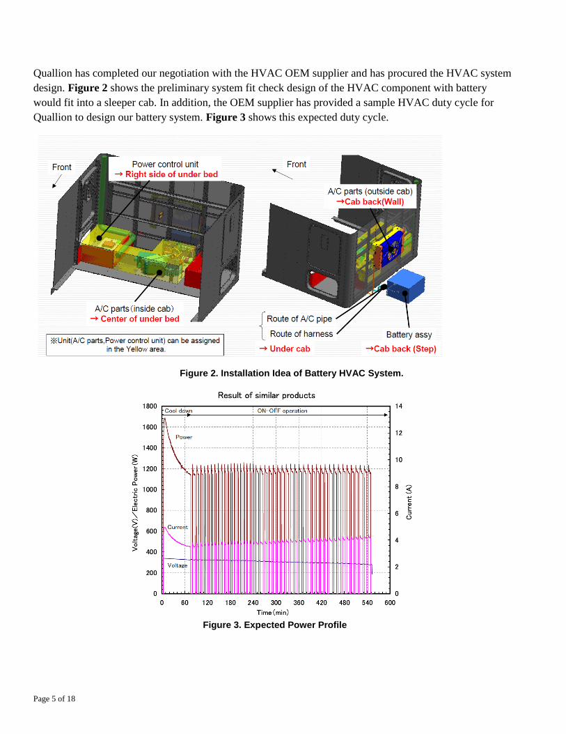
Quallion has completed our negotiation with the HVAC OEM supplier and has procured the HVAC system
design. Figure 2 shows the preliminary system fit check design of the HVAC component with battery
would fit into a sleeper cab. In addition, the OEM supplier has provided a sample HVAC duty cycle for
Quallion to design our battery system. Figure 3 shows this expected duty cycle.
Figure 2. Installation Idea of Battery HVAC System.
Figure 3. Expected Power Profile
Page 6 of 18
3.2 Quallion All Electric HVAC System Design
(Proprietary Data Redacted)
Figure 4. Quallion System Design
Quallion’s all electric HVAC system design uses a 6kWh battery to power an HVAC system. The battery
can be charged via two methods:
1. Truck Engine
2. Plug-in (to electric circuit); the Quallion system is unique as it has the capability to be plugged in.
The system battery charges in 3 hours via an AC-DC inverter with either method of charging. The ability to
charge in two modes makes the system more efficient and allows for extended use anti-idling even when the
truck is not driven for an extended period.
The battery system discharge also has two modes:
1. A 12V discharge that allows for the powering of HVAC components such as the condenser, blower
and/or evaporator. And,
2. A 288V discharge that powers an electric compressor that powers the Air Conditioning compressor.
The high voltage discharge option is a critical design element as it improves system efficiency. If a low-rate
discharge were to power an electric compressor for an air conditioner, much of the battery energy would be
dissipated in the process. The high-voltage design thereby allows for a smaller battery system overall that is
capable of supporting an HVAC system for a class 9 truck. The system designed is theoretically capable of
cooling a truck cab for at least 9 hours.
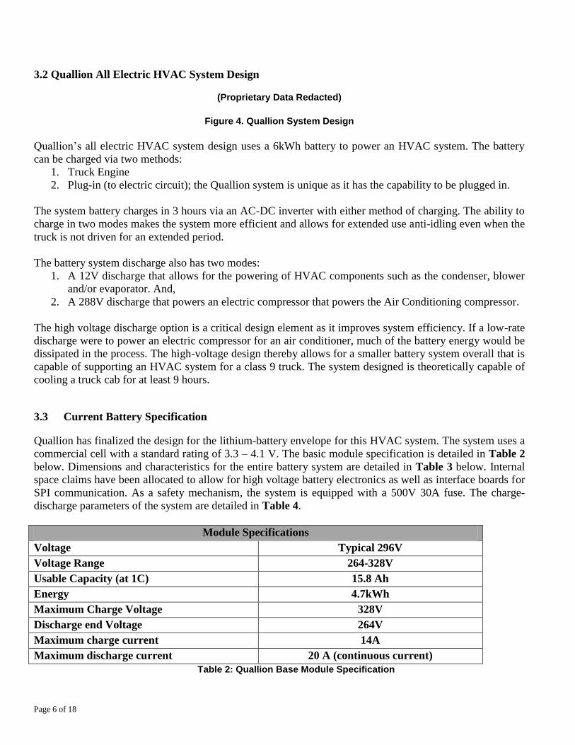
3.3 Current Battery Specification
Quallion has finalized the design for the lithium-battery envelope for this HVAC system. The system uses a
commercial cell with a standard rating of 3.3 – 4.1 V. The basic module specification is detailed in Table 2
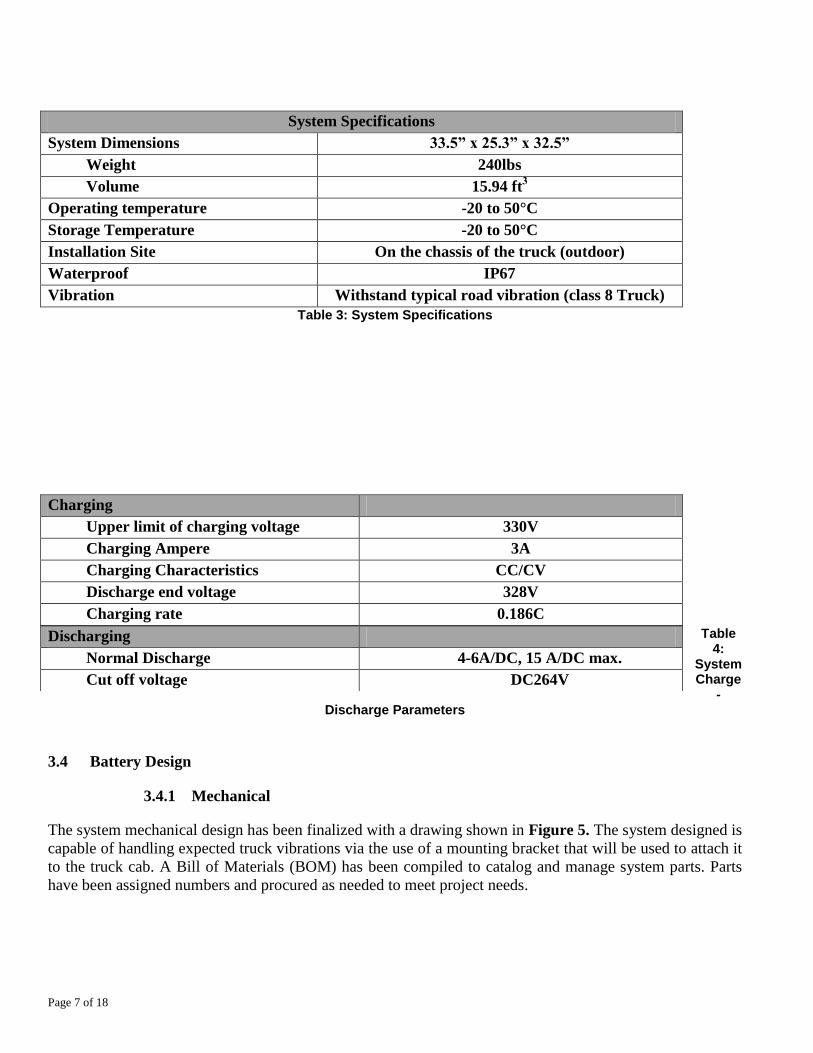
below. Dimensions and characteristics for the entire battery system are detailed in Table 3 below. Internal
space claims have been allocated to allow for high voltage battery electronics as well as interface boards for
SPI communication. As a safety mechanism, the system is equipped with a 500V 30A fuse. The charge-
discharge parameters of the system are detailed in Table 4.
Module Specifications
Voltage Typical 296V
Voltage Range 264-328V
Usable Capacity (at 1C) 15.8 Ah
Energy 4.7kWh
Maximum Charge Voltage 328V
Discharge end Voltage 264V
Maximum charge current 14A
Maximum discharge current 20 A (continuous current)
Table 2: Quallion Base Module Specification
Page 7 of 18
System Specifications
System Dimensions 33.5” x 25.3” x 32.5”
Weight 240lbs
Volume 15.94 ft3
Operating temperature -20 to 50°C
Storage Temperature -20 to 50°C
Installation Site On the chassis of the truck (outdoor)
Waterproof IP67
Vibration Withstand typical road vibration (class 8 Truck)
Table 3: System Specifications
Charging
Upper limit of charging voltage 330V
Charging Ampere 3A
Charging Characteristics CC/CV
Discharge end voltage 328V
Charging rate 0.186C
Table 4:
System Charge
-Discharge Parameters
3.4 Battery Design
3.4.1 Mechanical
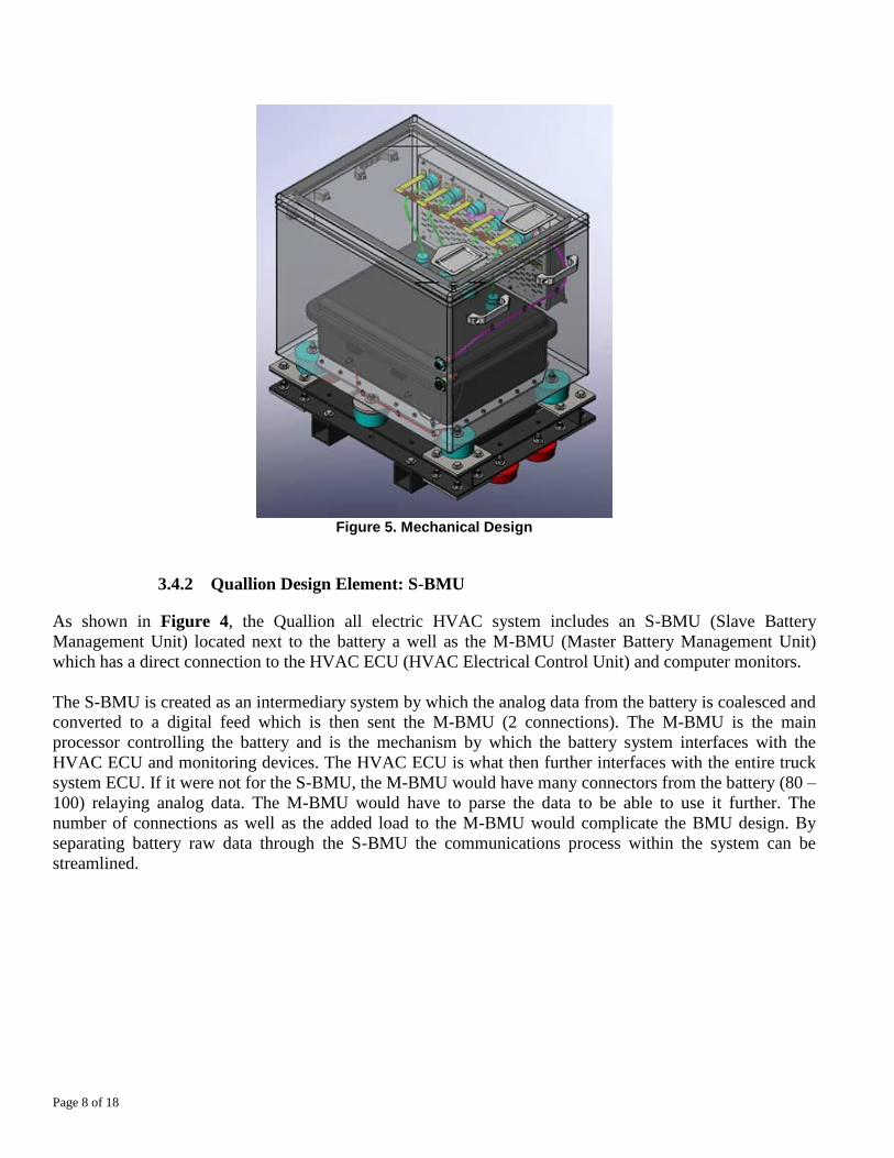
The system mechanical design has been finalized with a drawing shown in Figure 5. The system designed is
capable of handling expected truck vibrations via the use of a mounting bracket that will be used to attach it
to the truck cab. A Bill of Materials (BOM) has been compiled to catalog and manage system parts. Parts
have been assigned numbers and procured as needed to meet project needs.
Discharging
Normal Discharge 4-6A/DC, 15 A/DC max.
Cut off voltage DC264V
Page 8 of 18
Figure 5. Mechanical Design
3.4.2 Quallion Design Element: S-BMU
As shown in Figure 4, the Quallion all electric HVAC system includes an S-BMU (Slave Battery
Management Unit) located next to the battery a well as the M-BMU (Master Battery Management Unit)
which has a direct connection to the HVAC ECU (HVAC Electrical Control Unit) and computer monitors.
The S-BMU is created as an intermediary system by which the analog data from the battery is coalesced and
converted to a digital feed which is then sent the M-BMU (2 connections). The M-BMU is the main
processor controlling the battery and is the mechanism by which the battery system interfaces with the
HVAC ECU and monitoring devices. The HVAC ECU is what then further interfaces with the entire truck
system ECU. If it were not for the S-BMU, the M-BMU would have many connectors from the battery (80 –
100) relaying analog data. The M-BMU would have to parse the data to be able to use it further. The
number of connections as well as the added load to the M-BMU would complicate the BMU design. By
separating battery raw data through the S-BMU the communications process within the system can be
streamlined.
Page 9 of 18
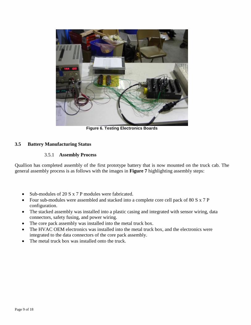
Figure 6. Testing Electronics Boards
3.5 Battery Manufacturing Status
3.5.1 Assembly Process
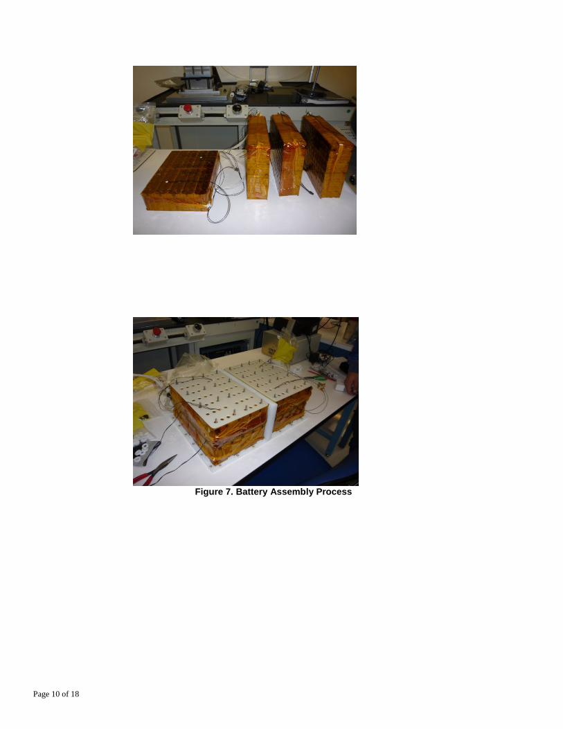
Quallion has completed assembly of the first prototype battery that is now mounted on the truck cab. The
general assembly process is as follows with the images in Figure 7 highlighting assembly steps:
Sub-modules of 20 S x 7 P modules were fabricated.
Four sub-modules were assembled and stacked into a complete core cell pack of 80 S x 7 P
configuration.
The stacked assembly was installed into a plastic casing and integrated with sensor wiring, data
connectors, safety fusing, and power wiring.
The core pack assembly was installed into the metal truck box.
The HVAC OEM electronics was installed into the metal truck box, and the electronics were
integrated to the data connectors of the core pack assembly.
The metal truck box was installed onto the truck.
Page 10 of 18
Figure 7. Battery Assembly Process
Page 11 of 18
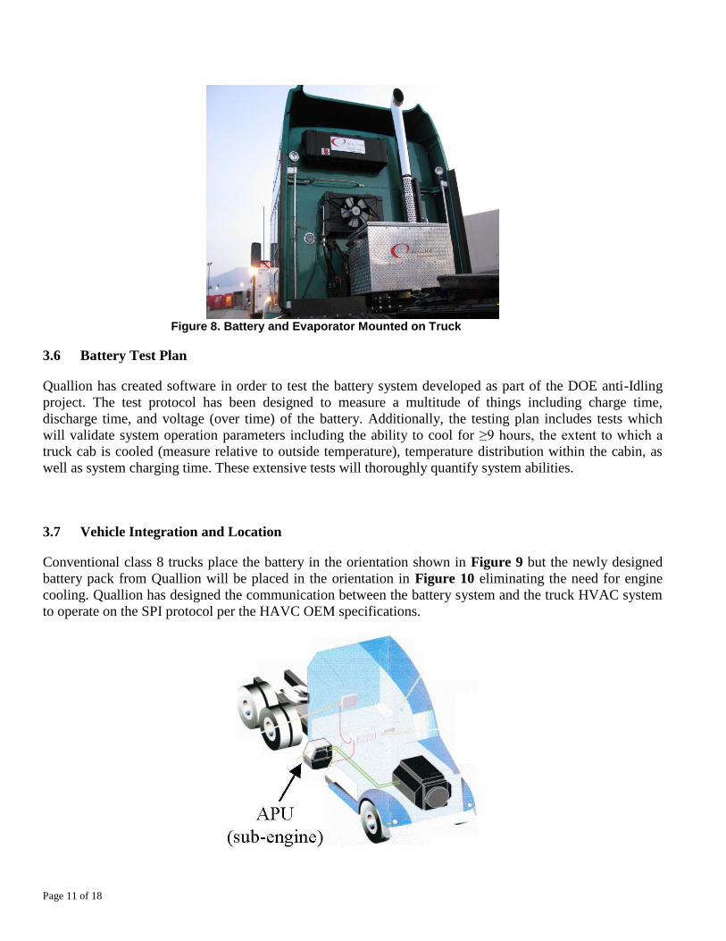
Figure 8. Battery and Evaporator Mounted on Truck
3.6 Battery Test Plan
Quallion has created software in order to test the battery system developed as part of the DOE anti-Idling
project. The test protocol has been designed to measure a multitude of things including charge time,
discharge time, and voltage (over time) of the battery. Additionally, the testing plan includes tests which
will validate system operation parameters including the ability to cool for ≥9 hours, the extent to which a
truck cab is cooled (measure relative to outside temperature), temperature distribution within the cabin, as
well as system charging time. These extensive tests will thoroughly quantify system abilities.
3.7 Vehicle Integration and Location
Conventional class 8 trucks place the battery in the orientation shown in Figure 9 but the newly designed
battery pack from Quallion will be placed in the orientation in Figure 10 eliminating the need for engine
cooling. Quallion has designed the communication between the battery system and the truck HVAC system
to operate on the SPI protocol per the HAVC OEM specifications.
Page 12 of 18
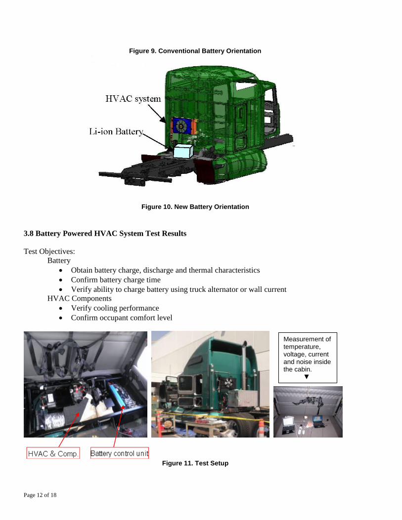
Figure 9. Conventional Battery Orientation
Figure 10. New Battery Orientation
3.8 Battery Powered HVAC System Test Results
Test Objectives:
Battery
Obtain battery charge, discharge and thermal characteristics
Confirm battery charge time
Verify ability to charge battery using truck alternator or wall current
HVAC Components
Verify cooling performance
Confirm occupant comfort level
Figure 11. Test Setup
Measurement of temperature, voltage, current and noise inside the cabin. ▼
Page 13 of 18
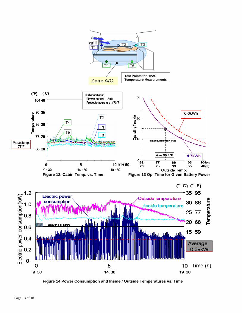
Figure 12. Cabin Temp. vs. Time Figure 13 Op. Time for Given Battery Power
Figure 14 Power Consumption and Inside / Outside Temperatures vs. Time
Test Points for HVAC Temperature Measurements
Page 14 of 18
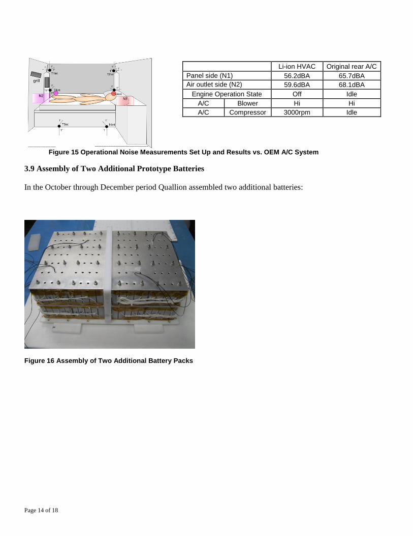
Figure 15 Operational Noise Measurements Set Up and Results vs. OEM A/C System
3.9 Assembly of Two Additional Prototype Batteries
In the October through December period Quallion assembled two additional batteries:
Figure 16 Assembly of Two Additional Battery Packs
Li-ion HVAC Original rear A/C
Panel side (N1) 56.2dBA 65.7dBA
Air outlet side (N2) 59.6dBA 68.1dBA
Engine Operation State Off Idle
A/C Blower Hi Hi
A/C Compressor 3000rpm Idle
Page 15 of 18
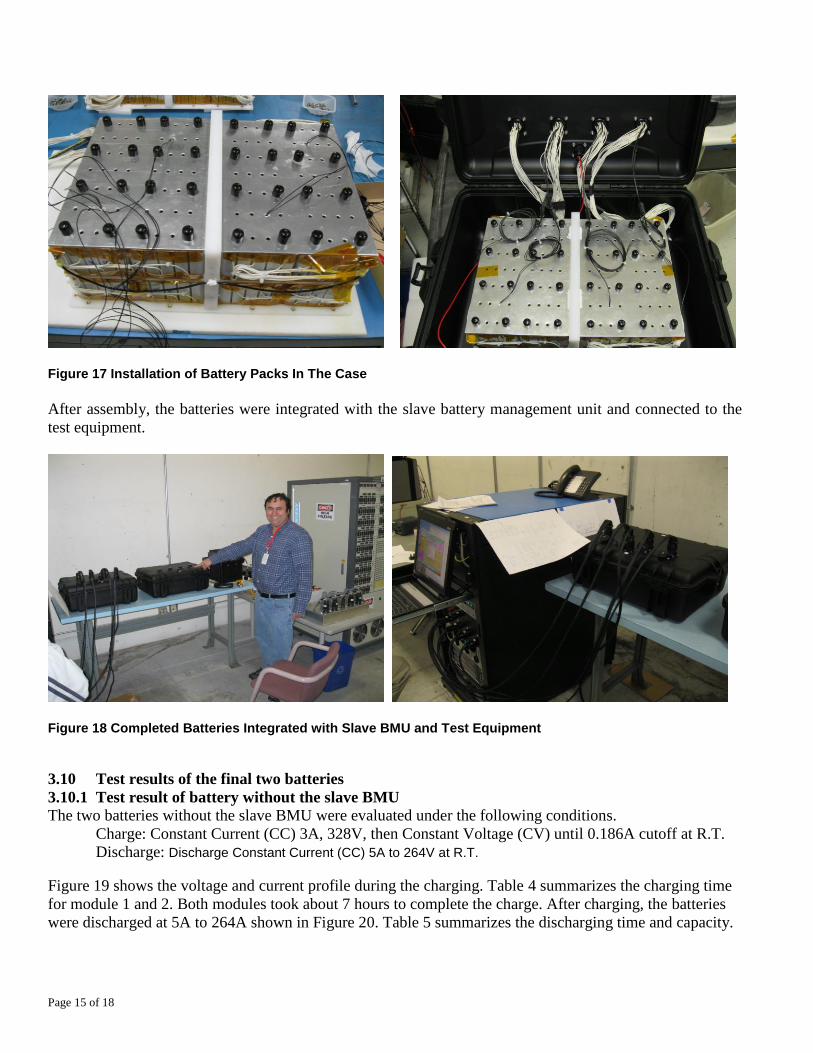
Figure 17 Installation of Battery Packs In The Case
After assembly, the batteries were integrated with the slave battery management unit and connected to the
test equipment.
Figure 18 Completed Batteries Integrated with Slave BMU and Test Equipment
3.10 Test results of the final two batteries
3.10.1 Test result of battery without the slave BMU
The two batteries without the slave BMU were evaluated under the following conditions.
Charge: Constant Current (CC) 3A, 328V, then Constant Voltage (CV) until 0.186A cutoff at R.T.
Discharge: Discharge Constant Current (CC) 5A to 264V at R.T.
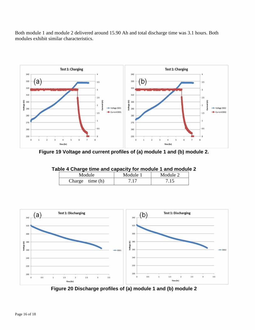
Figure 19 shows the voltage and current profile during the charging. Table 4 summarizes the charging time
for module 1 and 2. Both modules took about 7 hours to complete the charge. After charging, the batteries
were discharged at 5A to 264A shown in Figure 20. Table 5 summarizes the discharging time and capacity.
Page 16 of 18
Both module 1 and module 2 delivered around 15.90 Ah and total discharge time was 3.1 hours. Both
modules exhibit similar characteristics.
Figure 19 Voltage and current profiles of (a) module 1 and (b) module 2.
Table 4 Charge time and capacity for module 1 and module 2 Module Module 1 Module 2
Charge time (h) 7.17 7.15
Figure 20 Discharge profiles of (a) module 1 and (b) module 2
Page 17 of 18
Table 5 Discharge time and capacity for module 1 and module 2 Module Module 1 Module 2
Discharge time (h) 3.16 3.19
Discharge capacity (Ah) 15.80 15.95
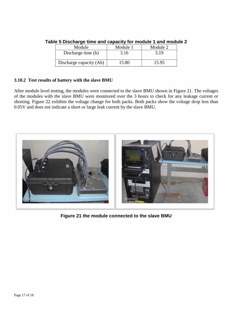
3.10.2 Test results of battery with the slave BMU
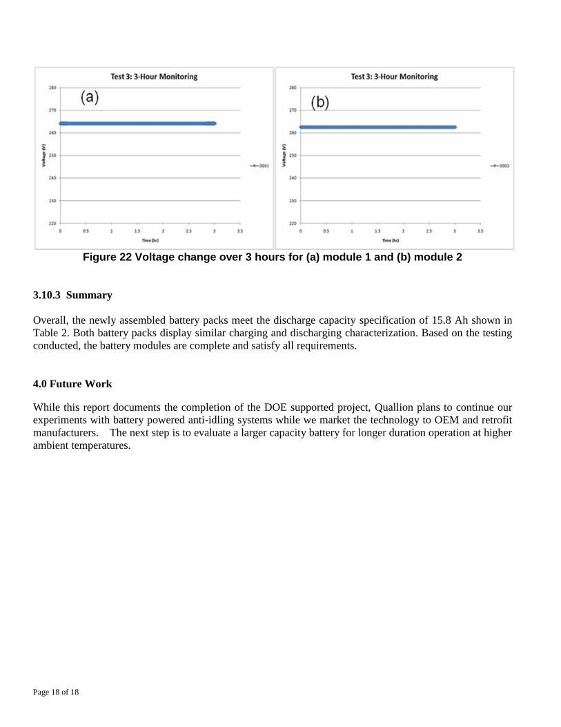
After module level testing, the modules were connected to the slave BMU shown in Figure 21. The voltages
of the modules with the slave BMU were monitored over the 3 hours to check for any leakage current or
shorting. Figure 22 exhibits the voltage change for both packs. Both packs show the voltage drop less than
0.05V and does not indicate a short or large leak current by the slave BMU.
Figure 21 the module connected to the slave BMU
Page 18 of 18
Figure 22 Voltage change over 3 hours for (a) module 1 and (b) module 2
3.10.3 Summary
Overall, the newly assembled battery packs meet the discharge capacity specification of 15.8 Ah shown in
Table 2. Both battery packs display similar charging and discharging characterization. Based on the testing
conducted, the battery modules are complete and satisfy all requirements.
4.0 Future Work
While this report documents the completion of the DOE supported project, Quallion plans to continue our
experiments with battery powered anti-idling systems while we market the technology to OEM and retrofit
manufacturers. The next step is to evaluate a larger capacity battery for longer duration operation at higher
ambient temperatures.