Embed Size (px)
DESCRIPTION
well tests
Citation preview

A System Architecture To EstablishBest Practice in the Design,
Execution and Interpretation ofWell Tests
Nicholas Reilly
A report submitted as part of the requirements
for the degree of MSc in IT for the Oil and Gas Industry
at the School of Computing Science and Digital Media
Robert Gordon University, Aberdeen, Scotland
September 2014
Supervisor Dr. Daniel C. Doolan
Abstract
Well Testing is a practice in the Oil and Gas Industry which is used in a variety of
different circumstances to obtain data or to plan operations on a particular well in a
reservoir. One of the issues faced in the Oil and Gas Industry particularly within the
field of Well Testing, is that large portions of knowledge and information known about
these practices are held tacitly and are not sufficiently well documented. Through
collaboration and team work this information can be shared amongst engineers when
required however the lack of documentation introduces problems for new or junior
engineers who do not posses such industry experience.
This research report is carried out in collaboration with Schlumberger to identify the
current processes that are in place for the various areas of Well Testing and to produce a
concept architecture which will allow for engineers to design, interpret and execute well
testing operations based on best practices. This project investigates the use of Mind
Map software packages to store Well Test knowledge and how these maps can be further
manipulated to be quantifiable to create added value. In order to create a viable system
architecture for the project, a number of programmes working in collaboration are
required to provide the necessary data processing and manipulation techniques. This
is comprised of a mind map application to act as a knowledge store, a prototype data
visualisation and manipulation tool developed in a programming language to process
the knowledge based data and also the use of a database to store/query and access
processed data.
The purpose of the architecture is to educate engineers about best practice decision
making when designing, executing and interpreting well tests. This would involve
engineers referencing a Mind Map to understand the process behind a particular well
test, and through data processing and parametric user input, a list of tools that are
most effective for that well test will be derived and proposed as a recommendation for
the engineer based on best-practices.
ii

Acknowledgements
I would firstly like to thank my supervisor Dr. Daniel C. Doolan for his guidance,
support and valuable advice throughout the duration of the project.
I would also like to thank Tony Fitzpatrick from Schlumberger for giving me the oppor-
tunity to deliver an industry relevant project for Schlumberger and for his continuous
collaboration throughout the project. A special thanks is due to all the staff from ADTi
and Schlumberger who were also consulted during the project.
Finally I would like to pay thanks to my family, girlfriend and friends for their continued
support and encouragement.
iii

Declaration
I confirm that the work contained in this MSc project report has been
composed solely by myself and has not been accepted in any previ-
ous application for a degree. All sources of information have been
specifically acknowledged and all verbatim extracts are distinguished
by quotation marks.
Signed ............................................ Date ......................
Nicholas Reilly
iv
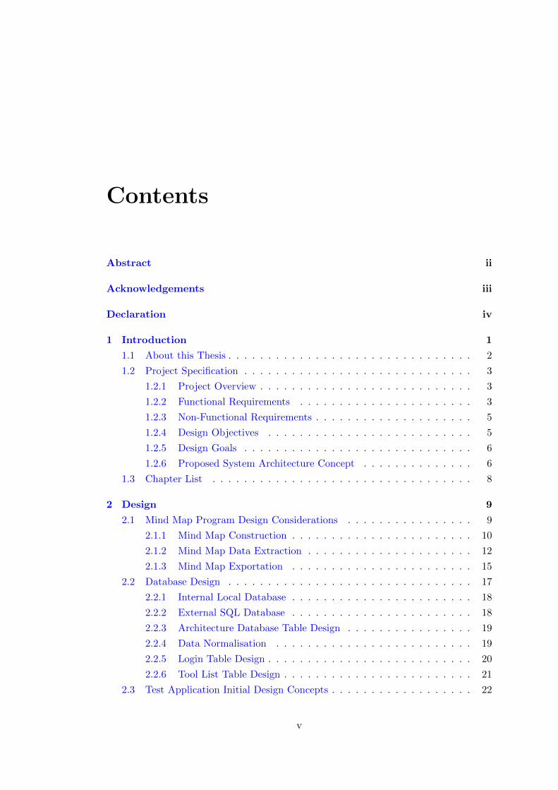
Contents
Abstract ii
Acknowledgements iii
Declaration iv
1 Introduction 1
1.1 About this Thesis . . . . . . . . . . . . . . . . . . . . . . . . . . . . . . . 2
1.2 Project Specification . . . . . . . . . . . . . . . . . . . . . . . . . . . . . 3
1.2.1 Project Overview . . . . . . . . . . . . . . . . . . . . . . . . . . . 3
1.2.2 Functional Requirements . . . . . . . . . . . . . . . . . . . . . . 3
1.2.3 Non-Functional Requirements . . . . . . . . . . . . . . . . . . . . 5
1.2.4 Design Objectives . . . . . . . . . . . . . . . . . . . . . . . . . . 5
1.2.5 Design Goals . . . . . . . . . . . . . . . . . . . . . . . . . . . . . 6
1.2.6 Proposed System Architecture Concept . . . . . . . . . . . . . . 6
1.3 Chapter List . . . . . . . . . . . . . . . . . . . . . . . . . . . . . . . . . 8
2 Design 9
2.1 Mind Map Program Design Considerations . . . . . . . . . . . . . . . . 9
2.1.1 Mind Map Construction . . . . . . . . . . . . . . . . . . . . . . . 10
2.1.2 Mind Map Data Extraction . . . . . . . . . . . . . . . . . . . . . 12
2.1.3 Mind Map Exportation . . . . . . . . . . . . . . . . . . . . . . . 15
2.2 Database Design . . . . . . . . . . . . . . . . . . . . . . . . . . . . . . . 17
2.2.1 Internal Local Database . . . . . . . . . . . . . . . . . . . . . . . 18
2.2.2 External SQL Database . . . . . . . . . . . . . . . . . . . . . . . 18
2.2.3 Architecture Database Table Design . . . . . . . . . . . . . . . . 19
2.2.4 Data Normalisation . . . . . . . . . . . . . . . . . . . . . . . . . 19
2.2.5 Login Table Design . . . . . . . . . . . . . . . . . . . . . . . . . . 20
2.2.6 Tool List Table Design . . . . . . . . . . . . . . . . . . . . . . . . 21
2.3 Test Application Initial Design Concepts . . . . . . . . . . . . . . . . . . 22
v
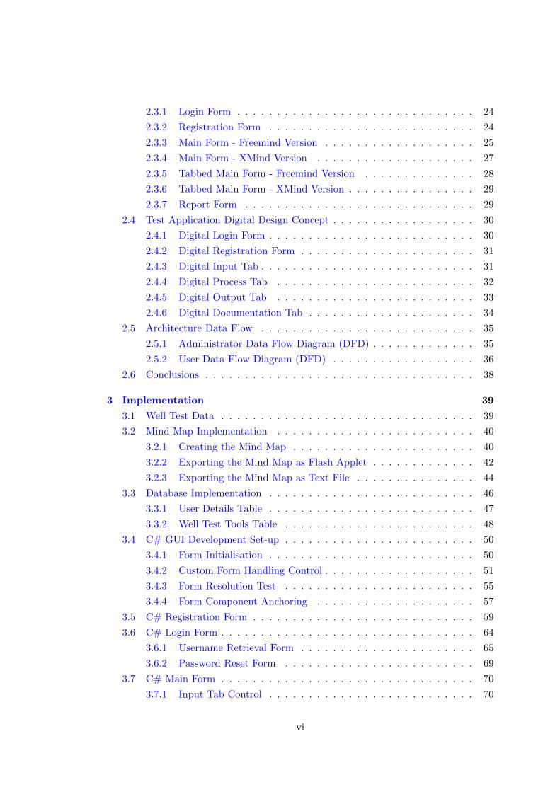
2.3.1 Login Form . . . . . . . . . . . . . . . . . . . . . . . . . . . . . . 24
2.3.2 Registration Form . . . . . . . . . . . . . . . . . . . . . . . . . . 24
2.3.3 Main Form - Freemind Version . . . . . . . . . . . . . . . . . . . 25
2.3.4 Main Form - XMind Version . . . . . . . . . . . . . . . . . . . . 27
2.3.5 Tabbed Main Form - Freemind Version . . . . . . . . . . . . . . 28
2.3.6 Tabbed Main Form - XMind Version . . . . . . . . . . . . . . . . 29
2.3.7 Report Form . . . . . . . . . . . . . . . . . . . . . . . . . . . . . 29
2.4 Test Application Digital Design Concept . . . . . . . . . . . . . . . . . . 30
2.4.1 Digital Login Form . . . . . . . . . . . . . . . . . . . . . . . . . . 30
2.4.2 Digital Registration Form . . . . . . . . . . . . . . . . . . . . . . 31
2.4.3 Digital Input Tab . . . . . . . . . . . . . . . . . . . . . . . . . . . 31
2.4.4 Digital Process Tab . . . . . . . . . . . . . . . . . . . . . . . . . 32
2.4.5 Digital Output Tab . . . . . . . . . . . . . . . . . . . . . . . . . 33
2.4.6 Digital Documentation Tab . . . . . . . . . . . . . . . . . . . . . 34
2.5 Architecture Data Flow . . . . . . . . . . . . . . . . . . . . . . . . . . . 35
2.5.1 Administrator Data Flow Diagram (DFD) . . . . . . . . . . . . . 35
2.5.2 User Data Flow Diagram (DFD) . . . . . . . . . . . . . . . . . . 36
2.6 Conclusions . . . . . . . . . . . . . . . . . . . . . . . . . . . . . . . . . . 38
3 Implementation 39
3.1 Well Test Data . . . . . . . . . . . . . . . . . . . . . . . . . . . . . . . . 39
3.2 Mind Map Implementation . . . . . . . . . . . . . . . . . . . . . . . . . 40
3.2.1 Creating the Mind Map . . . . . . . . . . . . . . . . . . . . . . . 40
3.2.2 Exporting the Mind Map as Flash Applet . . . . . . . . . . . . . 42
3.2.3 Exporting the Mind Map as Text File . . . . . . . . . . . . . . . 44
3.3 Database Implementation . . . . . . . . . . . . . . . . . . . . . . . . . . 46
3.3.1 User Details Table . . . . . . . . . . . . . . . . . . . . . . . . . . 47
3.3.2 Well Test Tools Table . . . . . . . . . . . . . . . . . . . . . . . . 48
3.4 C# GUI Development Set-up . . . . . . . . . . . . . . . . . . . . . . . . 50
3.4.1 Form Initialisation . . . . . . . . . . . . . . . . . . . . . . . . . . 50
3.4.2 Custom Form Handling Control . . . . . . . . . . . . . . . . . . . 51
3.4.3 Form Resolution Test . . . . . . . . . . . . . . . . . . . . . . . . 55
3.4.4 Form Component Anchoring . . . . . . . . . . . . . . . . . . . . 57
3.5 C# Registration Form . . . . . . . . . . . . . . . . . . . . . . . . . . . . 59
3.6 C# Login Form . . . . . . . . . . . . . . . . . . . . . . . . . . . . . . . . 64
3.6.1 Username Retrieval Form . . . . . . . . . . . . . . . . . . . . . . 65
3.6.2 Password Reset Form . . . . . . . . . . . . . . . . . . . . . . . . 69
3.7 C# Main Form . . . . . . . . . . . . . . . . . . . . . . . . . . . . . . . . 70
3.7.1 Input Tab Control . . . . . . . . . . . . . . . . . . . . . . . . . . 70
vi
3.7.2 Processing Tab Control . . . . . . . . . . . . . . . . . . . . . . . 76
3.7.3 Output Tab Control . . . . . . . . . . . . . . . . . . . . . . . . . 83
3.7.4 Document Tab Control . . . . . . . . . . . . . . . . . . . . . . . 86
3.7.5 User Help Form . . . . . . . . . . . . . . . . . . . . . . . . . . . . 89
3.8 Conclusions . . . . . . . . . . . . . . . . . . . . . . . . . . . . . . . . . . 91
4 Evaluation & Testing 92
4.1 Testing . . . . . . . . . . . . . . . . . . . . . . . . . . . . . . . . . . . . 92
4.1.1 Mind Map Data Export . . . . . . . . . . . . . . . . . . . . . . . 92
4.1.2 Database Table Creation . . . . . . . . . . . . . . . . . . . . . . 95
4.1.3 Resolution Display . . . . . . . . . . . . . . . . . . . . . . . . . . 96
4.1.4 Custom Form Handling Controls . . . . . . . . . . . . . . . . . . 96
4.1.5 Successful User Registration . . . . . . . . . . . . . . . . . . . . . 97
4.1.6 Registered Details Emailed to User . . . . . . . . . . . . . . . . . 97
4.1.7 Forgotten Username Retrieval . . . . . . . . . . . . . . . . . . . . 98
4.1.8 Forgotten Password Reset . . . . . . . . . . . . . . . . . . . . . . 98
4.1.9 Successful User Login . . . . . . . . . . . . . . . . . . . . . . . . 99
4.1.10 Internal Display of Mind Map Flash Applet . . . . . . . . . . . . 100
4.1.11 Take Screen-shot of Entire Form . . . . . . . . . . . . . . . . . . 101
4.1.12 Load Screen-shot to Crop Tool . . . . . . . . . . . . . . . . . . . 101
4.1.13 Screen-shot Cropped Appropriately . . . . . . . . . . . . . . . . . 102
4.1.14 Crop Controls Functionality . . . . . . . . . . . . . . . . . . . . . 103
4.1.15 Extracted Map Text File Loaded . . . . . . . . . . . . . . . . . . 103
4.1.16 Text File Loaded Into Tree Control . . . . . . . . . . . . . . . . . 104
4.1.17 Tree Nodes Drag and Drop . . . . . . . . . . . . . . . . . . . . . 105
4.1.18 Process Dropped Tree Nodes Against DB . . . . . . . . . . . . . 106
4.1.19 Processed Tree Nodes Return Tools . . . . . . . . . . . . . . . . 106
4.1.20 Custom Tree Control . . . . . . . . . . . . . . . . . . . . . . . . . 107
4.1.21 Display Tool List Database Table . . . . . . . . . . . . . . . . . . 107
4.1.22 Add, Remove, Save Database Entries . . . . . . . . . . . . . . . . 108
4.1.23 Creation of PDF Document . . . . . . . . . . . . . . . . . . . . . 108
4.1.24 View Created PDF Document . . . . . . . . . . . . . . . . . . . 108
4.1.25 Display User Help Tutorials . . . . . . . . . . . . . . . . . . . . . 109
4.2 Evaluation . . . . . . . . . . . . . . . . . . . . . . . . . . . . . . . . . . . 111
4.3 Conclusions . . . . . . . . . . . . . . . . . . . . . . . . . . . . . . . . . . 114
5 Conclusion 115
5.1 Conclusions . . . . . . . . . . . . . . . . . . . . . . . . . . . . . . . . . . 115
5.2 Future Work . . . . . . . . . . . . . . . . . . . . . . . . . . . . . . . . . 116
vii

Bibliography 117
A XSLT Data Export Script 119
B Project Management 120
C Presentation Slides 122
D Project Log 124
viii
List of Tables
3.1 Freemind Node Short-Cut’s . . . . . . . . . . . . . . . . . . . . . . . . . 41
ix
List of Figures
1.1 Proposed Architecture Solution for project . . . . . . . . . . . . . . . . . 7
2.1 Internal Map Linking . . . . . . . . . . . . . . . . . . . . . . . . . . . . . 10
2.2 Single Map Construction . . . . . . . . . . . . . . . . . . . . . . . . . . . 11
2.3 Full Map Extraction . . . . . . . . . . . . . . . . . . . . . . . . . . . . . 13
2.4 Partial Map Extraction . . . . . . . . . . . . . . . . . . . . . . . . . . . 14
2.5 XSLT Map Extraction . . . . . . . . . . . . . . . . . . . . . . . . . . . . 15
2.6 Freemind Image Export . . . . . . . . . . . . . . . . . . . . . . . . . . . 16
2.7 Freemind HTML Export . . . . . . . . . . . . . . . . . . . . . . . . . . . 16
2.8 Freemind Flash Applet . . . . . . . . . . . . . . . . . . . . . . . . . . . . 17
2.9 Login Table Design . . . . . . . . . . . . . . . . . . . . . . . . . . . . . . 21
2.10 Tool List Table Design . . . . . . . . . . . . . . . . . . . . . . . . . . . . 22
2.11 Overall Structure of C# Test Application . . . . . . . . . . . . . . . . . 23
2.12 Login Form Design . . . . . . . . . . . . . . . . . . . . . . . . . . . . . . 24
2.13 Registration Form Design . . . . . . . . . . . . . . . . . . . . . . . . . . 25
2.14 Main Form Design using Freemind . . . . . . . . . . . . . . . . . . . . . 26
2.15 Main Form Design using XMind . . . . . . . . . . . . . . . . . . . . . . 27
2.16 Tabbed Main Form Design using Freemind . . . . . . . . . . . . . . . . 28
2.17 Tabbed Main Form Design using XMind . . . . . . . . . . . . . . . . . . 29
2.18 Login Form Digital Concept . . . . . . . . . . . . . . . . . . . . . . . . . 30
2.19 Register Form Digital Concept . . . . . . . . . . . . . . . . . . . . . . . 31
2.20 Main Form Tab 1 Digital Concept . . . . . . . . . . . . . . . . . . . . . 32
2.21 Main Form Tab 2 Digital Concept . . . . . . . . . . . . . . . . . . . . . 33
2.22 Main Form Tab 3 Digital Concept . . . . . . . . . . . . . . . . . . . . . 34
2.23 Main Form Tab 4 Digital Concept . . . . . . . . . . . . . . . . . . . . . 35
2.24 Administrator DFD . . . . . . . . . . . . . . . . . . . . . . . . . . . . . 36
2.25 User DFD . . . . . . . . . . . . . . . . . . . . . . . . . . . . . . . . . . . 37
3.1 Mind Map Data Structure . . . . . . . . . . . . . . . . . . . . . . . . . . 42
3.2 Flash Applet Export . . . . . . . . . . . . . . . . . . . . . . . . . . . . . 43
x
3.3 XSLT Export . . . . . . . . . . . . . . . . . . . . . . . . . . . . . . . . . 44
3.4 Copy and Paste Export . . . . . . . . . . . . . . . . . . . . . . . . . . . 45
3.5 Finalised User Details Table . . . . . . . . . . . . . . . . . . . . . . . . . 48
3.6 Finalised Well Test Tool Table . . . . . . . . . . . . . . . . . . . . . . . 50
3.7 Maximise/Restore Form Control . . . . . . . . . . . . . . . . . . . . . . 54
3.8 Common Screen Resolutions [1] . . . . . . . . . . . . . . . . . . . . . . . 56
3.9 Modified Screen Resolution . . . . . . . . . . . . . . . . . . . . . . . . . 57
3.10 Component Anchoring . . . . . . . . . . . . . . . . . . . . . . . . . . . . 58
3.11 wellTEST+ Custom Logo . . . . . . . . . . . . . . . . . . . . . . . . . . 59
3.12 wellTEST+ Form Layout . . . . . . . . . . . . . . . . . . . . . . . . . . 60
3.13 User Registration Components . . . . . . . . . . . . . . . . . . . . . . . 60
3.14 Registration Confirmation . . . . . . . . . . . . . . . . . . . . . . . . . . 62
3.15 Complete Registration Form . . . . . . . . . . . . . . . . . . . . . . . . . 63
3.16 Completed Login Form . . . . . . . . . . . . . . . . . . . . . . . . . . . . 65
3.17 Forgot Username Form . . . . . . . . . . . . . . . . . . . . . . . . . . . . 66
3.18 Username Retrieval through Encryption . . . . . . . . . . . . . . . . . . 68
3.19 Password Reset Form . . . . . . . . . . . . . . . . . . . . . . . . . . . . 69
3.20 Internal Display of Mind Map . . . . . . . . . . . . . . . . . . . . . . . . 71
3.21 Failed Mind Map Image Capture . . . . . . . . . . . . . . . . . . . . . . 72
3.22 Screen-shot Offset Error . . . . . . . . . . . . . . . . . . . . . . . . . . . 73
3.23 Inverse Offset Error . . . . . . . . . . . . . . . . . . . . . . . . . . . . . 73
3.24 Custom Crop Tool Layout . . . . . . . . . . . . . . . . . . . . . . . . . . 74
3.25 Cropped Image Using Tool . . . . . . . . . . . . . . . . . . . . . . . . . 75
3.26 Finalised Input Tab Control . . . . . . . . . . . . . . . . . . . . . . . . . 76
3.27 Text Editor for Mind Map Data . . . . . . . . . . . . . . . . . . . . . . 78
3.28 Mind Map Text File Hidden Characters . . . . . . . . . . . . . . . . . . 80
3.29 Successful Tree Implementation . . . . . . . . . . . . . . . . . . . . . . . 80
3.30 Drag And Drop Feature . . . . . . . . . . . . . . . . . . . . . . . . . . . 82
3.31 Well Test Tool List . . . . . . . . . . . . . . . . . . . . . . . . . . . . . . 84
3.32 Well Test Tools From Selection . . . . . . . . . . . . . . . . . . . . . . . 85
3.33 Completed Documentation Tab Control . . . . . . . . . . . . . . . . . . 88
3.34 User Help Video Tutorial . . . . . . . . . . . . . . . . . . . . . . . . . . 90
3.35 User Manual Document . . . . . . . . . . . . . . . . . . . . . . . . . . . 90
4.1 Mind Map Flash Applet Export Test . . . . . . . . . . . . . . . . . . . . 93
4.2 Mind Map XSLT Export Test . . . . . . . . . . . . . . . . . . . . . . . . 94
4.3 Mind Map Copy and Paste Output Test . . . . . . . . . . . . . . . . . . 94
4.4 Login Table Create and Populate Test . . . . . . . . . . . . . . . . . . . 95
4.5 Tool List Table Create and Populate Test . . . . . . . . . . . . . . . . . 95
xi
4.6 Screen Resolution Test . . . . . . . . . . . . . . . . . . . . . . . . . . . . 96
4.7 Custom Control Functionality Test . . . . . . . . . . . . . . . . . . . . . 96
4.8 User Registration Test . . . . . . . . . . . . . . . . . . . . . . . . . . . . 97
4.9 Email Verification Test . . . . . . . . . . . . . . . . . . . . . . . . . . . . 98
4.10 Forgotten User-name Retrieval Test . . . . . . . . . . . . . . . . . . . . 98
4.11 Reset Account Password Test . . . . . . . . . . . . . . . . . . . . . . . . 99
4.12 User Login Test . . . . . . . . . . . . . . . . . . . . . . . . . . . . . . . . 100
4.13 Internal Display of Mind Map Test . . . . . . . . . . . . . . . . . . . . . 101
4.14 Load Screen-shot to Crop Tool Test . . . . . . . . . . . . . . . . . . . . 102
4.15 Desired Screen-shot Area Cropped . . . . . . . . . . . . . . . . . . . . . 103
4.16 Load Extracted Mind Map Text File . . . . . . . . . . . . . . . . . . . . 104
4.17 Load Text File Into Tree Control . . . . . . . . . . . . . . . . . . . . . . 105
4.18 Tree Control Drag and Drop Test . . . . . . . . . . . . . . . . . . . . . . 105
4.19 Processing Tree Nodes Test . . . . . . . . . . . . . . . . . . . . . . . . . 106
4.20 Returned Tools From Tree Node Process . . . . . . . . . . . . . . . . . . 107
4.21 Display of Tool List Table . . . . . . . . . . . . . . . . . . . . . . . . . . 107
4.22 View created PDF document test . . . . . . . . . . . . . . . . . . . . . . 109
4.23 Display of user help video tutorial . . . . . . . . . . . . . . . . . . . . . 110
4.24 Display of user manual document . . . . . . . . . . . . . . . . . . . . . . 110
4.25 Overall User Rating of Application . . . . . . . . . . . . . . . . . . . . . 112
4.26 Individual Question Rating For First Five Users . . . . . . . . . . . . . 113
4.27 Individual Question Rating For Remaining Five Users . . . . . . . . . . 113
C.1 Title Slide . . . . . . . . . . . . . . . . . . . . . . . . . . . . . . . . . . . 122
C.2 Introduction Slide . . . . . . . . . . . . . . . . . . . . . . . . . . . . . . 122
C.3 Research Slide . . . . . . . . . . . . . . . . . . . . . . . . . . . . . . . . 122
C.4 Design Slide . . . . . . . . . . . . . . . . . . . . . . . . . . . . . . . . . . 122
C.5 Implementation Slide . . . . . . . . . . . . . . . . . . . . . . . . . . . . . 123
C.6 Testing Slide . . . . . . . . . . . . . . . . . . . . . . . . . . . . . . . . . 123
C.7 Conclusion Slide . . . . . . . . . . . . . . . . . . . . . . . . . . . . . . . 123
C.8 Questions Slide . . . . . . . . . . . . . . . . . . . . . . . . . . . . . . . . 123
xii
Listings
3.1 Create User Details Table . . . . . . . . . . . . . . . . . . . . . . . . . . 47
3.2 Insert Into User Details Table . . . . . . . . . . . . . . . . . . . . . . . . 48
3.3 Create Tool List Table . . . . . . . . . . . . . . . . . . . . . . . . . . . . 49
3.4 Insert Into Tool List Table . . . . . . . . . . . . . . . . . . . . . . . . . . 49
3.5 Close Button Functionality . . . . . . . . . . . . . . . . . . . . . . . . . 52
3.6 Minimise Button Functionality . . . . . . . . . . . . . . . . . . . . . . . 53
3.7 Maximise/Restore Button Functionality . . . . . . . . . . . . . . . . . . 54
3.8 Custom Form Movement . . . . . . . . . . . . . . . . . . . . . . . . . . . 55
3.9 Register Details Database Connection . . . . . . . . . . . . . . . . . . . 61
3.10 Email Registration Details . . . . . . . . . . . . . . . . . . . . . . . . . . 62
3.11 SQL Login Verification . . . . . . . . . . . . . . . . . . . . . . . . . . . . 64
3.12 Username Encryption and Decryption . . . . . . . . . . . . . . . . . . . 67
3.13 Password Reset Method . . . . . . . . . . . . . . . . . . . . . . . . . . . 70
3.14 Attempt of Mind Map Image Capture . . . . . . . . . . . . . . . . . . . 72
3.15 Extracted Map Text File in Application . . . . . . . . . . . . . . . . . . 77
3.16 Tree Population Code . . . . . . . . . . . . . . . . . . . . . . . . . . . . 79
3.17 Custom Tree Control . . . . . . . . . . . . . . . . . . . . . . . . . . . . . 81
3.18 Additional Database Functionality . . . . . . . . . . . . . . . . . . . . . 84
3.19 Well Test Tool From Selection . . . . . . . . . . . . . . . . . . . . . . . . 86
3.20 Code to Create PDF Document . . . . . . . . . . . . . . . . . . . . . . . 87
3.21 Code to View PDF Documents . . . . . . . . . . . . . . . . . . . . . . . 88
A.1 Mind Map XSLT Script . . . . . . . . . . . . . . . . . . . . . . . . . . . 119
xiii

Chapter 1
Introduction
This chapter details some background information about the about the issues that this
project will investigate and explains how the contents of the report will be structured.
The first licences for oil and gas extraction from the North Sea were fifty years ago
in 1964. During this time around forty two billion barrels of oil have been produced
and due to the ever increasing value of oil and gas this has resulted the Oil and Gas
Industry becoming one of the most fortuitous bodies in business in the United Kingdom
and worldwide. The industry employs over 450,000 people across the United Kingdom
and in 2012-2013 paid over £6.5 billion in taxes to the government. Alongside this, in
2012 the North Sea supplied 67% of the UK’s oil and 53% of the country’s gas demand.
These statistics demonstrate how important the Oil and Gas Industry is for the UK’s
economic stability. Since peaking in 1999, the production of oil and gas has steadily
declined and there is estimated to be 30-40 years remaining with potentially 24 billion
barrels of recoverable oil existing in untapped reserves. With these factors in mind
one of the major objectives of the Oil and Gas Industry is to maximise efficiency in
infrastructure and exploration to exploit these untapped reserves in order to increase
the industries forecast revenue [2].
This industry has developed over many years and through experience and dedication
has significantly advanced it’s processes and technology to continue quality development
and production to meet current industry expectations and demand. There are a variety
of different technical areas involved in the Oil and Gas sector however this report
will focus on Well Testing and in particular the processes that are currently used by
Schlumberger to provide well testing services.
One of the main issues regarding well testing processes is that actions are predominantly
carried out based on engineer’s personal experience and knowledge. This is not to say
1
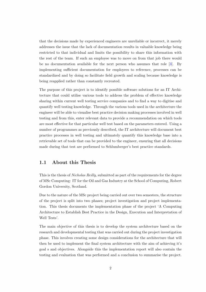
that the decisions made by experienced engineers are unreliable or incorrect, it merely
addresses the issue that the lack of documentation results in valuable knowledge being
restricted to that individual and limits the possibility to share this information with
the rest of the team. If such an employee was to move on from that job there would
be no documentation available for the next person who assumes that role [3]. By
implementing sufficient documentation for employees to reference, processes can be
standardized and by doing so facilitate field growth and scaling because knowledge is
being reapplied rather than constantly recreated.
The purpose of this project is to identify possible software solutions for an IT Archi-
tecture that could utilise various tools to address the problem of effective knowledge
sharing within current well testing service companies and to find a way to digitise and
quantify well testing knowledge. Through the various tools used in the architecture the
engineer will be able to visualise best practice decision making processes involved in well
testing and from this, enter relevant data to provide a recommendation on which tools
are most effective for that particular well test based on the parameters entered. Using a
number of programmes as previously described, the IT architecture will document best
practice processes in well testing and ultimately quantify this knowledge base into a
retrievable set of tools that can be provided to the engineer, ensuring that all decisions
made during that test are performed to Schlumberger’s best practice standards.
1.1 About this Thesis
This is the thesis of Nicholas Reilly, submitted as part of the requirements for the degree
of MSc Computing: IT for the Oil and Gas Industry at the School of Computing, Robert
Gordon University, Scotland.
Due to the nature of the MSc project being carried out over two semesters, the structure
of the project is split into two phases; project investigation and project implementa-
tion. This thesis documents the implementation phase of the project ‘A Computing
Architecture to Establish Best Practice in the Design, Execution and Interpretation of
Well Tests’.
The main objective of this thesis is to develop the system architecture based on the
research and developmental testing that was carried out during the project investigation
phase. This involves creating some design considerations for the architecture that will
then be used to implement the final system architecture with the aim of achieving it’s
goal s and objectives. Alongside this the implementation report will also contain the
testing and evaluation that was performed and a conclusion to summarise the project.
2

1.2 Project Specification
This section details the specifications of the project including concept design sketches
of the application, programme interaction and also elements such as functional and
non-functional requirements.
1.2.1 Project Overview
The main body of this project is to evaluate system architectures that could be im-
plemented to achieve the goal of using mind map software with external technologies
to establish best practice decision making when designing, interpreting or executing
a well test. The architecture will incorporate the use of mind mapping software in
conjunction with an external test application to quantify this knowledge base and from
this provide recommendations on which tools are required for the test. An additional
feature of this knowledge-based process would be the incorporation of pricing quota
related to the tools that have been selected for that particular well test.
The main objectives of the project are as follows:
• Identify Mind Map software that could be used to store/explore well test knowl-
edge
• Test application developed to manipulate the knowledge-base contained in the
Mind Map software
• Establish effective data storage method to store information about Schlumberger
tools however also could be used to handle data that is produced from the test
application
1.2.2 Functional Requirements
This section details the functional requirements of the project that will be implemented
in the final delivered architecture. This specifies the basic required functionality in
order for the architecture to work efficiently however there may be additional functional
requirements that are introduced over the course of the project if necessary. The fully
functional architecture should allow:
3
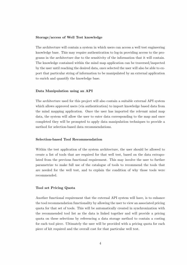
Storage/access of Well Test knowledge
The architecture will contain a system in which users can access a well test engineering
knowledge base. This may require authentication to log-in providing access to the pro-
grams in the architecture due to the sensitivity of the information that it will contain.
The knowledge contained within the mind map application can be traversed/inspected
by the user until reaching the desired data, once selected the user will also be able to ex-
port that particular string of information to be manipulated by an external application
to enrich and quantify the knowledge base.
Data Manipulation using an API
The architecture used for this project will also contain a suitable external API system
which allows approved users (via authentication) to import knowledge based data from
the mind mapping application. Once the user has imported the relevant mind map
data, the system will allow the user to enter data corresponding to the map and once
completed they will be prompted to apply data manipulation techniques to provide a
method for selection-based data recommendations.
Selection-based Tool Recommendation
Within the test application of the system architecture, the user should be allowed to
create a list of tools that are required for that well test, based on the data extrapo-
lated from the previous functional requirement. This may involve the user to further
parametrize to make full use of the catalogue of tools to recommend the tools that
are needed for the well test, and to explain the condition of why those tools were
recommended.
Tool set Pricing Quota
Another functional requirement that the external API system will have, is to enhance
the tool recommendation functionality by allowing the user to view an associated pricing
quota for that set of tools. This will be automatically created in synchronization with
the recommended tool list as the data is linked together and will provide a pricing
quota on these selections by referencing a data storage method to contain a costing
for each tool piece. Ultimately the user will be provided with a pricing quota for each
piece of kit required and the overall cost for that particular well test.
4

1.2.3 Non-Functional Requirements
Non-functional requirements detail possible constraints that may be apparent over the
duration of the project. These constraints are to be considered throughout the course
of the project and are detailed as follows:
• The project must be developed, implemented and also tested by 1st September
2014
• The project should establish a suitable architecture that could be adapted/en-
hanced for future developments
• The project will be created on a Toshiba Satellite Laptop with 8Gb of RAM and
a Quad-Core AMD A6 processor
• Any operational/hosting costs are to be kept to a minimum, unless required by
the client
• Measures of security are to be in place to ensure data security and confidentiality
• Any interface used (mind map application or external API) must be user-friendly
to accommodate any level of PC user
• The overall architecture should be cross-platform deployable
1.2.4 Design Objectives
The design objectives of the project details reasonable features that will be incorporated
into the finished design of the overall system/architecture.
• The finished architecture system will be used with a standard mouse and keyboard
on any computer platform/laptop
• The system should be deployable on Windows, Mac and Linux operating systems
• Navigation between (and on) each respective system within the architecture
should be simple and easy to use, prompting the user with what action to take
next
• The layout of systems in the architecture should follow a consistent design to be
attractive to the user and to ensure simplicity so that the user has an enjoyable
experience
5

• Feedback and prompts will be delivered in an appropriate manner to minimise
confusion for the user and to validate whether they are using the architecture for
it’s intended purpose
• The test application will have quick response times, ensuring the data desired by
the user can be obtained fast and efficiently
1.2.5 Design Goals
The design goals of the project differ slightly from the design objectives seen above.
Design goals refer to statements that are hoped to be achieved when using the system
architecture. This means that these goals are not guaranteed to be delivered, instead
they depend solely on the experience the user has when using the system. The design
goals hoped to be achieved from this project are featured in the list below.
• The system architecture will be methodical and simple to use
• The architecture will be fully functional and provide value to the user when using
the knowledge base
• Components within the architecture will be intuitive and provide the user with
necessary information required
• The architecture will be adaptable/expandable for future use or further develop-
ment
• The system will provide cost/benefit analysis to the user adding further value to
decisions made
• The overall architecture will be suitable and applicable to be used for all well
test engineers by meeting the requirements of multiple clients, for this project
Schlumberger and ADTi
1.2.6 Proposed System Architecture Concept
Figure 1.1 shows the proposed solution for the system architecture derived from the re-
search and exploratory development carried out during the project investigation phase.
This details the necessary components that are required to make the system architec-
ture function effectively and allow for the successful flow of data throughout.
It can be seen that the first component featured is the knowledge base data store
achieved by using a mind map software package. The stored information from the mind
6
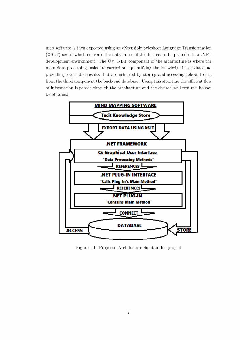
map software is then exported using an eXtensible Sylesheet Language Transformation
(XSLT) script which converts the data in a suitable format to be passed into a .NET
development environment. The C# .NET component of the architecture is where the
main data processing tasks are carried out quantifying the knowledge based data and
providing returnable results that are achieved by storing and accessing relevant data
from the third component the back-end database. Using this structure the efficient flow
of information is passed through the architecture and the desired well test results can
be obtained.
Figure 1.1: Proposed Architecture Solution for project
7

1.3 Chapter List
This project implementation report is structured into four key chapters; Design, Im-
plementation, Testing and Evaluation and finally Conclusion. This structure was used
to document the body of work that was carried out during the project implementation
phase, providing a logical flow of information that encompasses all the work that was
undertaken throughout the duration.
Chapter 2 Design. This chapter covers all of the relevant design considerations that
were made during the project implementation phase. This will document the design
of all the system architecture’s components covering mind maps, database, the test
application and finally the flow of data that will be present.
Chapter 3 Implementation. This chapter deals with the implementation of the system
architecture. This delves into the development of the mind map component, the back-
end database that was used and also the C# test application created to prove the
validity of the system, architecture.
Chapter 4 Evaluation & Testing. This chapter details the testing and evaluation
processes that were carried out on the system architecture to establish the effectiveness
and usability of the featured components. This helped to understand the strength and
weaknesses of the architecture and allowed for considerations to be made on how it
could be improved.
Chapter 5 Conclusion. The conclusions of the thesis are presented in this chapter.
This summarises the project as a whole by identifying if it was a success, if there were
any problems during implementation and finally if future developments were to be made
how it would be improved.
8

Chapter 2
Design
This chapter examines the design of the system architecture detailing the various tools
that are to be used in series to accomplish the desired task. One of the main design
constraints for the system architecture is for the test application to be developed in
C#. This is due to the main functionality of the architecture being tested through the
custom application to allow for the manipulation of data from various programmes. The
way in which the data flow is carried out through the architecture plays an important
part in the overall design concepts created as it is essential to maintain a logical flow
of data whilst ensuring the usability of the application is simple and effective to its
purpose.
Through this chapter the various aspects involved in the design of the system architec-
ture are documented. This encompasses the back-end processes, the front-end programs
and also communication and data flow between each of these components, all of which
are identified and refined.
2.1 Mind Map Program Design Considerations
Although there are vast amounts of mind map software packages available for commer-
cial or licensed use, it was evident from the project investigation stage that there are
two main software packages that could be considered most effective to be employed in
the system architecture; Freemind and XMind. In both cases the way in which the mind
maps are utilised will affect the operation of the system architecture in how it stores
and accesses well test knowledge. An attractive feature which is presented through
the use of both proposed mind map software packages is that data can be transferable
between the two due to similar data types/format. This allows for mind map data to be
9
interchangeable between programs thereby providing greater developmental flexibility.
Design considerations will be made for Freemind based on the research carried out in
the project investigation stage leaning towards this as being the most likely selection
for use in the system architecture.
2.1.1 Mind Map Construction
From the research carried out in the investigation stage of the project, it was deter-
mined that the way in which the mind map data store is constructed has a consequential
effect on the overall operation of the system architecture. There are two main ways
in which the data can be stored using Freemind, however it is the access of this data
through the C# test application which is affected by the construction. This is ulti-
mately the determining factor towards the efficient and consistent flow of data through
the architecture’s components.
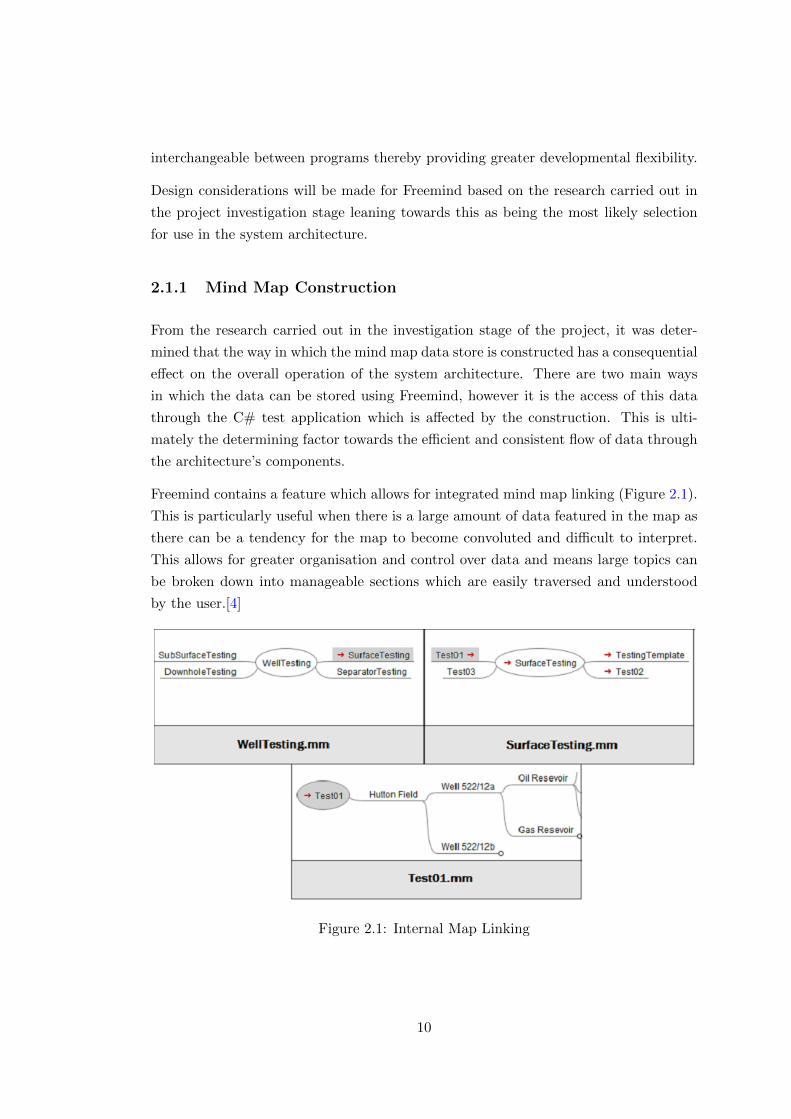
Freemind contains a feature which allows for integrated mind map linking (Figure 2.1).
This is particularly useful when there is a large amount of data featured in the map as
there can be a tendency for the map to become convoluted and difficult to interpret.
This allows for greater organisation and control over data and means large topics can
be broken down into manageable sections which are easily traversed and understood
by the user.[4]
Figure 2.1: Internal Map Linking
10
Although this provides easier and more efficient control over data in the map, in order
for all the data to be stored persistently, each linked map page needs to be saved in
the overall mind map project directory as an individual mind map document (.mm).
Through developmental component testing during the project investigation stage it
was established that this method of mind map data storage is ineffective for use in
the system architecture. This is due to the data being separated into individual files
meaning that the knowledge store is fragmented and by using the considered data
export method the complete and necessary data needed for the C# test application
cannot be retrieved.
In order to combat this issue another method can be used to allow the C# test appli-
cation to take in the complete data set, which will allow successful data flow between
the initial mind map component of the system architecture into the second component,
the C# test application.
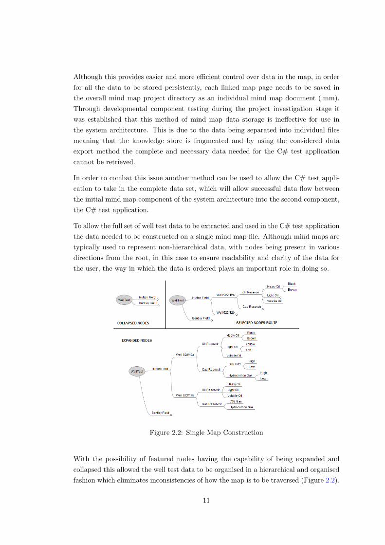
To allow the full set of well test data to be extracted and used in the C# test application
the data needed to be constructed on a single mind map file. Although mind maps are
typically used to represent non-hierarchical data, with nodes being present in various
directions from the root, in this case to ensure readability and clarity of the data for
the user, the way in which the data is ordered plays an important role in doing so.
Figure 2.2: Single Map Construction
With the possibility of featured nodes having the capability of being expanded and
collapsed this allowed the well test data to be organised in a hierarchical and organised
fashion which eliminates inconsistencies of how the map is to be traversed (Figure 2.2).
11
This provides a logical route for the user to take and in doing so organises the data
into key sections which can be established by the user allowing all the essential data to
be captured in the desired manner.
By using this method the full well test data set is present in the mind map and through
logical organising and simple node traversal the end result is easy for the user to follow.
This also has the benefit of allowing the C# test application to easily access the entire
data set allowing the flow of data to be efficient throughout the architecture to achieve
it’s desired goals for the user. With the mind map construction design now in place
the next aspect to be considered is how this data will be exported from the mind map
software package to then be used by the test application to quantify and add value to
this well test knowledge.
2.1.2 Mind Map Data Extraction
The purpose of the system architecture for this project is to show how external mind
maps software packages can be manipulated to add value to the data that it holds to
allow data processing techniques to be applied, and as a result turn the text based data
into quantifiable data that can ultimately be measured and provide related results.
In order to facilitate this it was determined during the project investigation stage that
there were two effective ways to achieve this which would convert the data into necessary
types that could be manipulated by a custom test application written in C#. Both of
these methods provide a text file representing the mind map map data in hierarchical
ordered fashion, however they differ slightly in the way that they are represented and
also how they are derived.
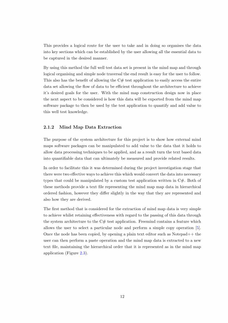
The first method that is considered for the extraction of mind map data is very simple
to achieve whilst retaining effectiveness with regard to the passing of this data through
the system architecture to the C# test application. Freemind contains a feature which
allows the user to select a particular node and perform a simple copy operation [5].
Once the node has been copied, by opening a plain text editor such as Notepad++ the
user can then perform a paste operation and the mind map data is extracted to a new
text file, maintaining the hierarchical order that it is represented as in the mind map
application (Figure 2.3).
12
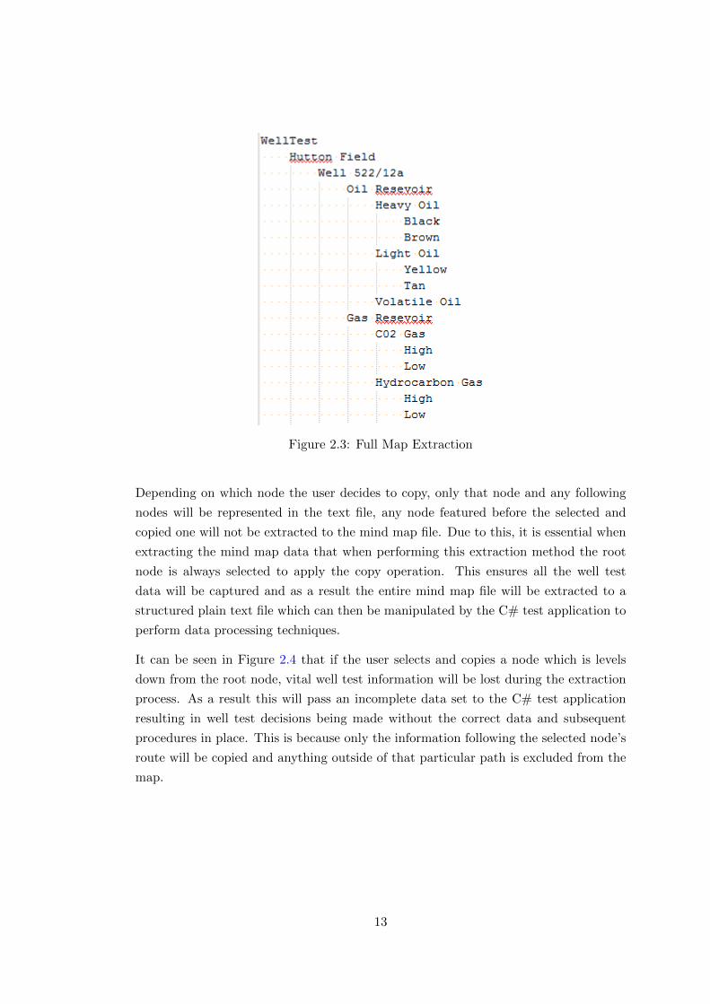
Figure 2.3: Full Map Extraction
Depending on which node the user decides to copy, only that node and any following
nodes will be represented in the text file, any node featured before the selected and
copied one will not be extracted to the mind map file. Due to this, it is essential when
extracting the mind map data that when performing this extraction method the root
node is always selected to apply the copy operation. This ensures all the well test
data will be captured and as a result the entire mind map file will be extracted to a
structured plain text file which can then be manipulated by the C# test application to
perform data processing techniques.
It can be seen in Figure 2.4 that if the user selects and copies a node which is levels
down from the root node, vital well test information will be lost during the extraction
process. As a result this will pass an incomplete data set to the C# test application
resulting in well test decisions being made without the correct data and subsequent
procedures in place. This is because only the information following the selected node’s
route will be copied and anything outside of that particular path is excluded from the
map.
13

Figure 2.4: Partial Map Extraction
This method is effective and easy to use however caution is required during extraction
to ensure that it is always the top level or root node that is selected to copy. This
ensures that all the data is captured and that the complete data set will be passed
onto the C# test application allowing full well test procedures to be identified then
processed.
The second considered method for extracting the mind map data can be achieved
through Freemind’s export data feature in the applications tool bar menu. This in-
volves using an eXtensible Stylesheet Language Transformations (XSLT) script when
exporting the mind map file which can be seen in Appendix A. [6]
By using this method the entire mind map file is converted upon export with a style
sheet which converts each level of the nodes in the map to be represented by comma-
separated values. This ensures that all data present in the map is converted and
represented in the same order it appears in the mind map application but has a spe-
cific amount of commas preceding it to identify the level of nesting that piece of data
possesses (Figure 2.5).
14
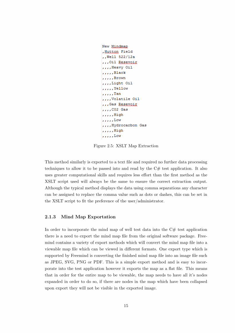
Figure 2.5: XSLT Map Extraction
This method similarly is exported to a text file and required no further data processing
techniques to allow it to be passed into and read by the C# test application. It also
uses greater computational skills and requires less effort than the first method as the
XSLT script used will always be the same to ensure the correct extraction output.
Although the typical method displays the data using comma separations any character
can be assigned to replace the comma value such as dots or dashes, this can be set in
the XSLT script to fit the preference of the user/administrator.
2.1.3 Mind Map Exportation
In order to incorporate the mind map of well test data into the C# test application
there is a need to export the mind map file from the original software package. Free-
mind contains a variety of export methods which will convert the mind map file into a
viewable map file which can be viewed in different formats. One export type which is
supported by Freemind is converting the finished mind map file into an image file such
as JPEG, SVG, PNG or PDF. This is a simple export method and is easy to incor-
porate into the test application however it exports the map as a flat file. This means
that in order for the entire map to be viewable, the map needs to have all it’s nodes
expanded in order to do so, if there are nodes in the map which have been collapsed
upon export they will not be visible in the exported image.
15
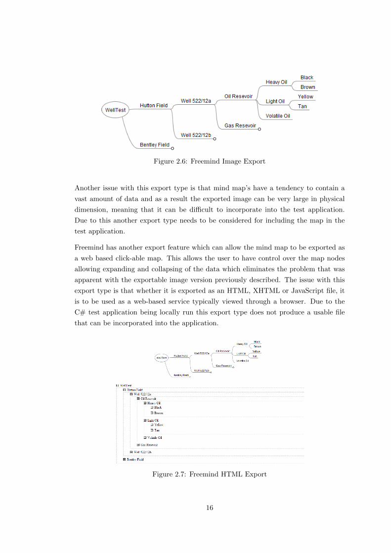
Figure 2.6: Freemind Image Export
Another issue with this export type is that mind map’s have a tendency to contain a
vast amount of data and as a result the exported image can be very large in physical
dimension, meaning that it can be difficult to incorporate into the test application.
Due to this another export type needs to be considered for including the map in the
test application.
Freemind has another export feature which can allow the mind map to be exported as
a web based click-able map. This allows the user to have control over the map nodes
allowing expanding and collapsing of the data which eliminates the problem that was
apparent with the exportable image version previously described. The issue with this
export type is that whether it is exported as an HTML, XHTML or JavaScript file, it
is to be used as a web-based service typically viewed through a browser. Due to the
C# test application being locally run this export type does not produce a usable file
that can be incorporated into the application.
Figure 2.7: Freemind HTML Export
16
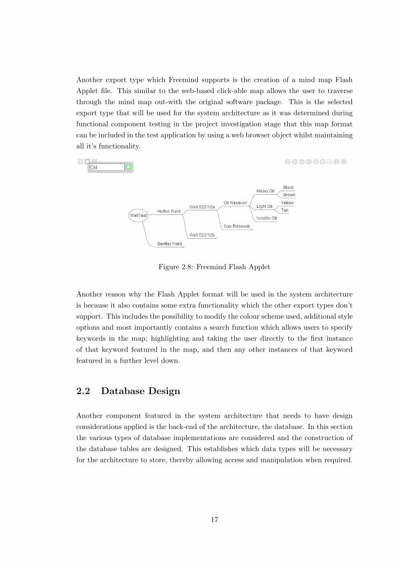
Another export type which Freemind supports is the creation of a mind map Flash
Applet file. This similar to the web-based click-able map allows the user to traverse
through the mind map out-with the original software package. This is the selected
export type that will be used for the system architecture as it was determined during
functional component testing in the project investigation stage that this map format
can be included in the test application by using a web browser object whilst maintaining
all it’s functionality.
Figure 2.8: Freemind Flash Applet
Another reason why the Flash Applet format will be used in the system architecture
is because it also contains some extra functionality which the other export types don’t
support. This includes the possibility to modify the colour scheme used, additional style
options and most importantly contains a search function which allows users to specify
keywords in the map; highlighting and taking the user directly to the first instance
of that keyword featured in the map, and then any other instances of that keyword
featured in a further level down.
2.2 Database Design
Another component featured in the system architecture that needs to have design
considerations applied is the back-end of the architecture, the database. In this section
the various types of database implementations are considered and the construction of
the database tables are designed. This establishes which data types will be necessary
for the architecture to store, thereby allowing access and manipulation when required.
17

2.2.1 Internal Local Database
Due to the test application being developed in C# one database design consideration
that can be made is the incorporation of an internal local database that is ran and
stored entirely through the test application’s project directory structure. This provides
the same functionality that is offered by external databases such as the storing and
access of database elements.
Using functional component testing during the project investigation stage it was dis-
covered that using a local database stored in the project’s directory there is actually
two instances of the database created in order for it work. One copy of the database is
stored at design time, the other at run time. This means that if modifications are made
to the database contents in the application, they will be saved whilst the program is
running however if the application is exited these changes are not stored persistently
as the database copy is then reverted back to the design time copy. This means that in
order to maintain data over both copies, the design time database information needs to
be manually overwritten by the run time copy, this removes the possibility of dynamic
update and should not be something required to be done by the user.
Another main issue that arises with this method is that it lacks security measures as
it is stored within the application’s file contents. This means that it if someone was
to gain access to the project’s directory there is a possibility that the database will be
subject to attack or modification. This is a particularly serious issue if the information
stored within is proprietary and confidential. Due to this, a design consideration was
made in which to remove this possibility of attack or modification by using a secure
external database as this is a better candidate for the system architecture. This is due
to the fact that contains the same if not more functionality and flexibility whilst also
implementing much greater security.
2.2.2 External SQL Database
Although the incorporation of a local database in the C# test application provides some
necessary functionality for efficient operation, there are aspects of it which introduce
inconsistencies and require additional user input which is not typically commonplace.
To address this issue the use of an external database would be the strongest considered
design option.
Microsoft SQL is one of the most supported and commonly used external databases
utilised across multiple disciplines in the computing industry [7]. Due to this, Microsoft
SQL Server 2012 is the recommended version of an SQL database that will be used for
18

the system architecture as it provides all the necessary functionality for storing and
accessing data and through mixed authentication (SQL and Windows) implements a
tight security measure that eliminates the risk of unauthorised access to the database
elements.
Another benefit of using a Microsoft SQL database is that it is simple to communicate
between the database and the C# test application as they are both Microsoft based
products, making connectivity between the two applications also very easy to achieve.
[8]
2.2.3 Architecture Database Table Design
It was established through functional component testing during the project investiga-
tion stage that for the system architecture it will be necessary for two tables to hold
the relevant data that will be featured. For this it is only required that one database
is implemented and using this database multiple tables can be created to separate and
store the according data.
2.2.4 Data Normalisation
A common task that is considered when designing database tables that will hold large
amounts of information is the normalization of data. This involves the organization of
fields that will be present in a relational database in order to minimise the possibility of
data redundancy and any dependencies that could be an affecting factor. This is typi-
cally addressed by dividing large tables into smaller and more manageable tables which
eliminate the possibility of redundant data by defining relationships that associated
data may have.
Normalization is a systematic approach that decomposes large tables to eliminate the
possibility of common anomalies such as insertion, update and deletion. During these
operations it is possible that data may be duplicated or alternatively removed invoking
redundancy by causing null values to be present.
The rule of normalization can be defined by three main states; First Normal Form
(1NF), Second Normal Form (2NF) and Third Normal Form (3NF). First Normal
Form incorporates the rule that no two rows of data featured in the table must contain
repeating groups and that each row should have a primary key to distinguish it is
a unique identifier. Second Normal Form invokes the same rules as featured in 1NF
however this also ensures that there are no partial dependencies on any column which
19
has a primary key. Third Normal form similarly contains the rules featured in 1NF and
2NF however it also applies that there are no transitive dependencies present.[9]
Due to the practice of well testing being a very large topic containing vast amounts
of potentially relevant data, a design consideration was made that a simple string of
information would be used for testing purposes. From this using First Normal Form
would be sufficient to ensure that the database would comply with a base rule of
normalization making sure the data is valid by applying a single primary key for each
table and that there are no redundant or duplicate values.
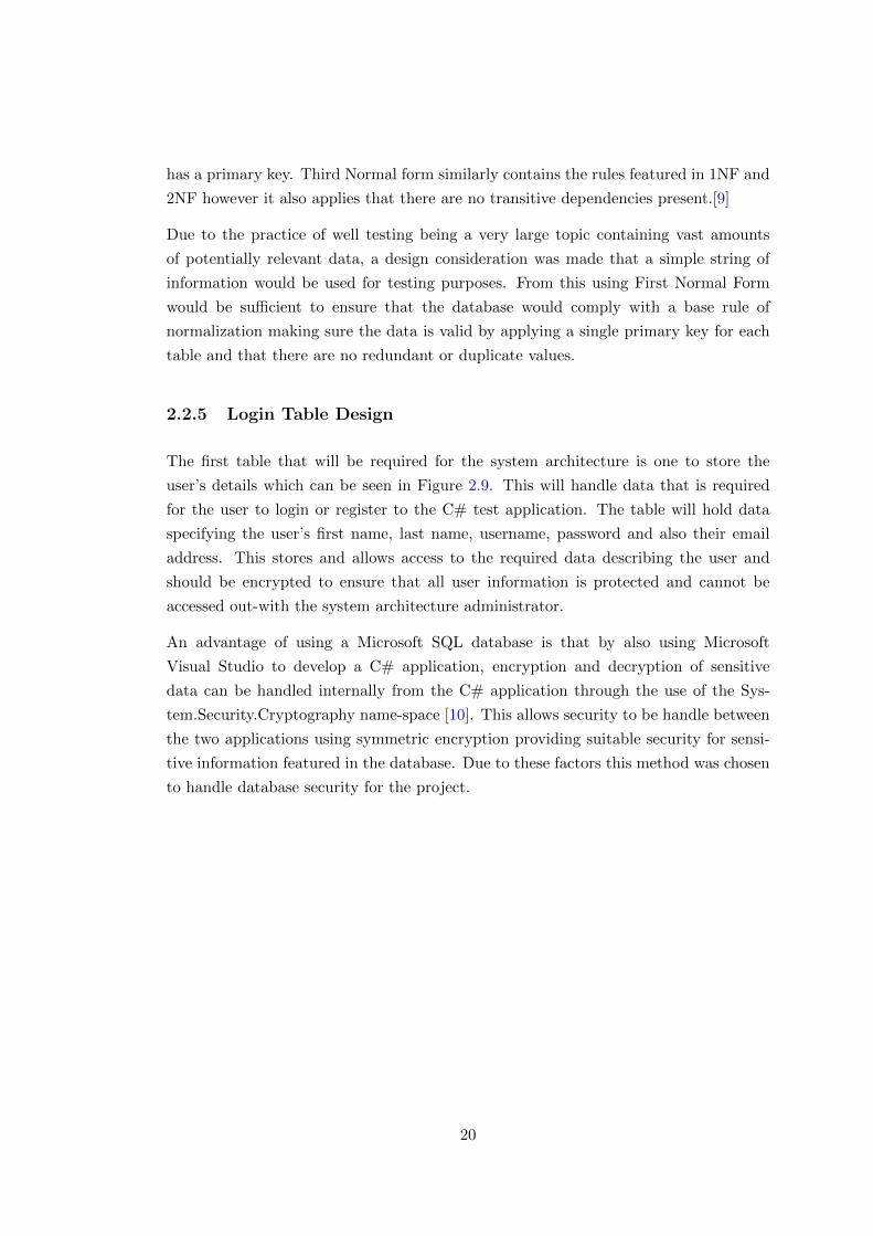
2.2.5 Login Table Design
The first table that will be required for the system architecture is one to store the
user’s details which can be seen in Figure 2.9. This will handle data that is required
for the user to login or register to the C# test application. The table will hold data
specifying the user’s first name, last name, username, password and also their email
address. This stores and allows access to the required data describing the user and
should be encrypted to ensure that all user information is protected and cannot be
accessed out-with the system architecture administrator.
An advantage of using a Microsoft SQL database is that by also using Microsoft
Visual Studio to develop a C# application, encryption and decryption of sensitive
data can be handled internally from the C# application through the use of the Sys-
tem.Security.Cryptography name-space [10]. This allows security to be handle between
the two applications using symmetric encryption providing suitable security for sensi-
tive information featured in the database. Due to these factors this method was chosen
to handle database security for the project.
20
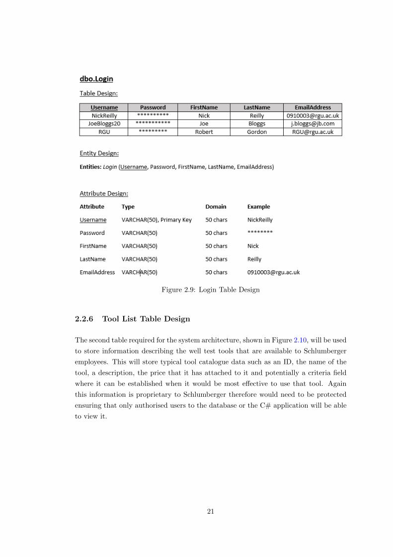
Figure 2.9: Login Table Design
2.2.6 Tool List Table Design
The second table required for the system architecture, shown in Figure 2.10, will be used
to store information describing the well test tools that are available to Schlumberger
employees. This will store typical tool catalogue data such as an ID, the name of the
tool, a description, the price that it has attached to it and potentially a criteria field
where it can be established when it would be most effective to use that tool. Again
this information is proprietary to Schlumberger therefore would need to be protected
ensuring that only authorised users to the database or the C# application will be able
to view it.
21

Figure 2.10: Tool List Table Design
2.3 Test Application Initial Design Concepts
This section of the design chapter details the initial concepts that were sketched to
represent the desired concept for the C# test application that will be used to carry
out the main tasks within the system architecture. The use of concept sketches are
an effective way to encapsulate the various forms that will be required within the
application and how these will be operated by the user to achieve the necessary tasks.
The design for the application is kept simple and will use the Pantone blue and white
colour scheme to represent Schlumberger’s company branding colours [11]. Due to the
potential of the programme being used by individuals with a wide range of computing
skills, a design consideration was made to ensure the application was simple to use and
that only the necessary components are to be present. From this, regardless of the level
of skill in using computers, engineers will be able to operate the program with ease,
increasing decision making time on well tests and improving efficiency.
It should be noted that the design of the C# test application takes into account Nielsen’s
ten usability heuristics for user interface design as follows:
22
1. Visibility of system status
2. Match between system and real world
3. User control and freedom
4. Consistency and standards
5. Error prevention
6. Recognition rather than recall
7. Flexibility and efficiency of use
8. Aesthetic and minimalistic design
9. Help users recognise, diagnose, and recover from errors
10. Help and documentation
By accounting for these broad rules of thumb, an effective final design will be reached
that will create a positive overall user experience when using the Graphical User Inter-
face (GUI)[12]. A design was created to determine how each form present in the C#
test application will link to one another and outlines the general process of tasks that
the user will be required to carry out in order to use the application as intended, shown
in Figure 2.11.
Figure 2.11: Overall Structure of C# Test Application
23
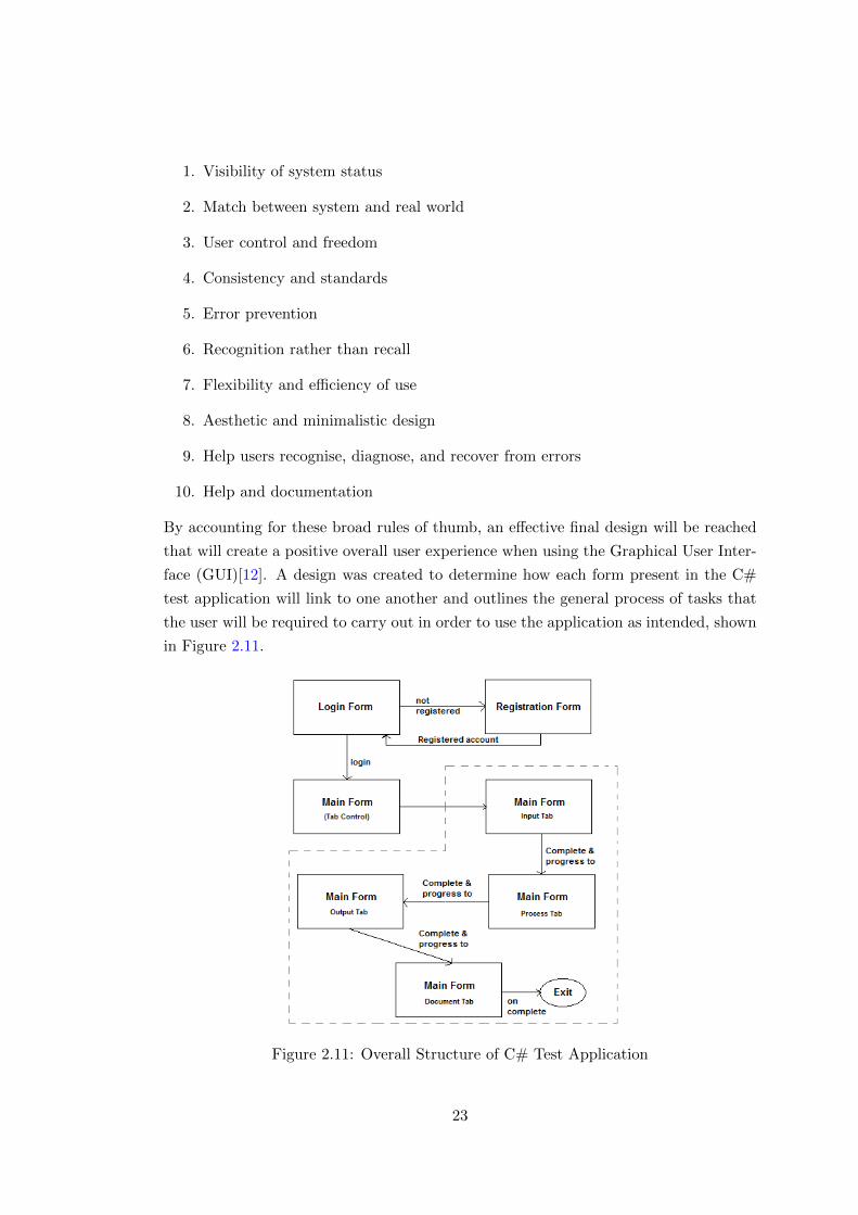
2.3.1 Login Form
The first form or page that would be required in the application would be the user
login. This is important, as the considered application would be used in an industry
environment, requiring the data held within the application to be proprietary infor-
mation of Schlumberger and the initial way to ensure this, is the incorporation of a
user login system. It can be seen in (Figure 2.12) that for this application there are
two fields, user name and password, in which the user would provide their details for
authentication and if correct access is granted to the application.
Figure 2.12: Login Form Design
With the incorporation of a user login system, unless the user already has an account
created for the application in order for other engineers to create a user account there
needs to be a form page in which they can register to do so.
2.3.2 Registration Form
Typically in any computer application, whether it be web-based or locally run, there
is a requirement for user login credentials to obtain access to the application. Due
to this project being carried out for Schlumberger, the data featured throughout the
architecture is proprietary information owned by the company so a necessary security
measure of a login system is to be implemented. Before the user is granted access to
the application there is the need to incorporate a user registration form which allows
them to create an account that consists of their details such as user-name, password,
first name, last name and also an email address (Figure 2.13).
24
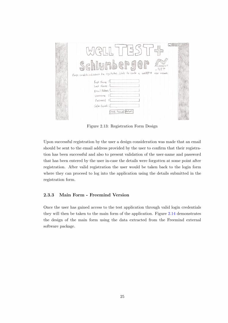
Figure 2.13: Registration Form Design
Upon successful registration by the user a design consideration was made that an email
should be sent to the email address provided by the user to confirm that their registra-
tion has been successful and also to present validation of the user-name and password
that has been entered by the user in-case the details were forgotten at some point after
registration. After valid registration the user would be taken back to the login form
where they can proceed to log into the application using the details submitted in the
registration form.
2.3.3 Main Form - Freemind Version
Once the user has gained access to the test application through valid login credentials
they will then be taken to the main form of the application. Figure 2.14 demonstrates
the design of the main form using the data extracted from the Freemind external
software package.
25
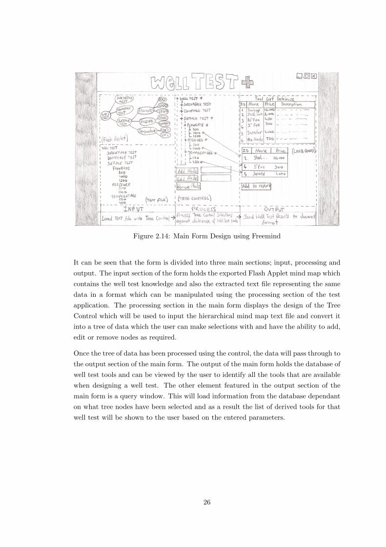
Figure 2.14: Main Form Design using Freemind
It can be seen that the form is divided into three main sections; input, processing and
output. The input section of the form holds the exported Flash Applet mind map which
contains the well test knowledge and also the extracted text file representing the same
data in a format which can be manipulated using the processing section of the test
application. The processing section in the main form displays the design of the Tree
Control which will be used to input the hierarchical mind map text file and convert it
into a tree of data which the user can make selections with and have the ability to add,
edit or remove nodes as required.
Once the tree of data has been processed using the control, the data will pass through to
the output section of the main form. The output of the main form holds the database of
well test tools and can be viewed by the user to identify all the tools that are available
when designing a well test. The other element featured in the output section of the
main form is a query window. This will load information from the database dependant
on what tree nodes have been selected and as a result the list of derived tools for that
well test will be shown to the user based on the entered parameters.
26
2.3.4 Main Form - XMind Version
Regardless of which mind map software package is used, Freemind or XMind, the
processing and output principles featured in the main form are consistent and will hold
the same design considerations in the way they will work and ultimately the data that
it will produce. However when using XMind as the well test data store, the input of
this information will differ to that of the Freemind software package. It can be seen
in Figure 2.15 that for the input section of the main form, the incorporation of the
XMind API is used to allow the user to initially create the XMind mind map file from
inside the test application and upon doing so the user is provided to a local address
link where the created mind map is stored. The user can click on this link to take them
to the file location where they can then open the map in the XMind software package.
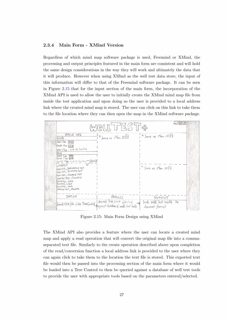
Figure 2.15: Main Form Design using XMind
The XMind API also provides a feature where the user can locate a created mind
map and apply a read operation that will convert the original map file into a comma-
separated text file. Similarly to the create operation described above upon completion
of the read/conversion function a local address link is provided to the user where they
can again click to take them to the location the text file is stored. This exported text
file would then be passed into the processing section of the main form where it would
be loaded into a Tree Control to then be queried against a database of well test tools
to provide the user with appropriate tools based on the parameters entered/selected.
27
2.3.5 Tabbed Main Form - Freemind Version
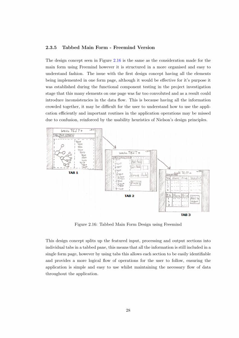
The design concept seen in Figure 2.16 is the same as the consideration made for the
main form using Freemind however it is structured in a more organised and easy to
understand fashion. The issue with the first design concept having all the elements
being implemented in one form page, although it would be effective for it’s purpose it
was established during the functional component testing in the project investigation
stage that this many elements on one page was far too convoluted and as a result could
introduce inconsistencies in the data flow. This is because having all the information
crowded together, it may be difficult for the user to understand how to use the appli-
cation efficiently and important routines in the application operations may be missed
due to confusion, reinforced by the usability heuristics of Nielson’s design principles.
Figure 2.16: Tabbed Main Form Design using Freemind
This design concept splits up the featured input, processing and output sections into
individual tabs in a tabbed pane, this means that all the information is still included in a
single form page, however by using tabs this allows each section to be easily identifiable
and provides a more logical flow of operations for the user to follow, ensuring the
application is simple and easy to use whilst maintaining the necessary flow of data
throughout the application.
28
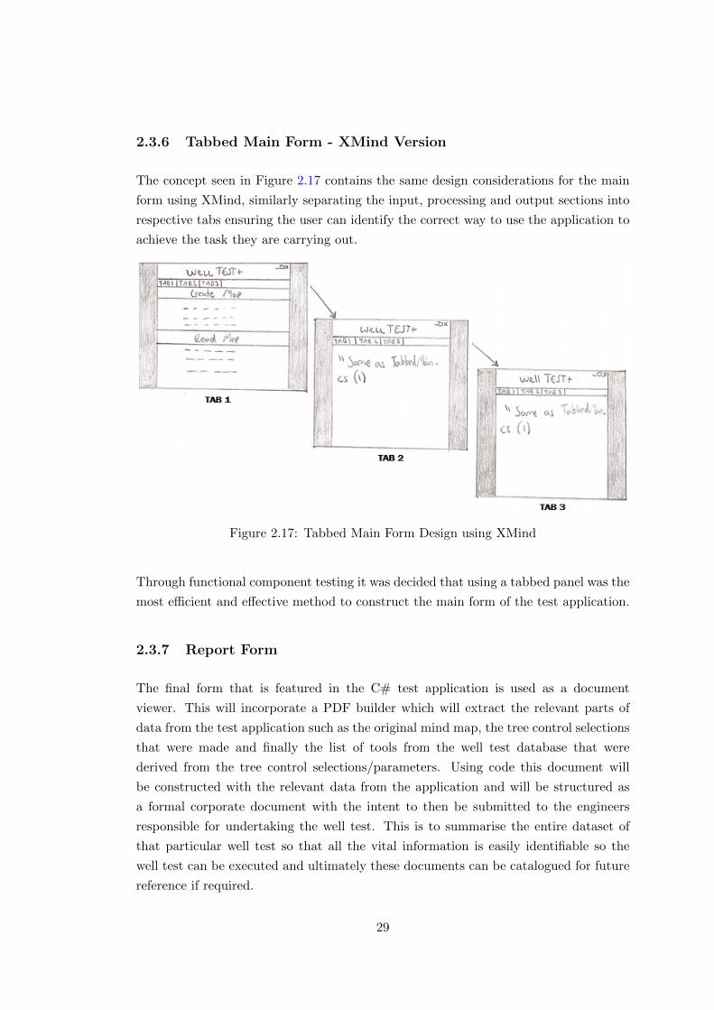
2.3.6 Tabbed Main Form - XMind Version
The concept seen in Figure 2.17 contains the same design considerations for the main
form using XMind, similarly separating the input, processing and output sections into
respective tabs ensuring the user can identify the correct way to use the application to
achieve the task they are carrying out.
Figure 2.17: Tabbed Main Form Design using XMind
Through functional component testing it was decided that using a tabbed panel was the
most efficient and effective method to construct the main form of the test application.
2.3.7 Report Form
The final form that is featured in the C# test application is used as a document
viewer. This will incorporate a PDF builder which will extract the relevant parts of
data from the test application such as the original mind map, the tree control selections
that were made and finally the list of tools from the well test database that were
derived from the tree control selections/parameters. Using code this document will
be constructed with the relevant data from the application and will be structured as
a formal corporate document with the intent to then be submitted to the engineers
responsible for undertaking the well test. This is to summarise the entire dataset of
that particular well test so that all the vital information is easily identifiable so the
well test can be executed and ultimately these documents can be catalogued for future
reference if required.
29

2.4 Test Application Digital Design Concept
This section takes the best considered option from the initial design concept sketches
and digitises them to convey how the application will look in digital form, incorporating
all the featured elements and also including the colour scheme that will be implemented
to ensure the C# test application will be styled effectively.
2.4.1 Digital Login Form
Figure 2.18 displays the digital concept created for the initial form featured in the C#
test application. As described in the initial design concept for the login form, this is
where the user provides their user-name and password to gain access to the program.
This is achieved with two text field entries which will be confirmed against the database
used to hold the user data when the login button is pressed.
Figure 2.18: Login Form Digital Concept
The colour scheme used for the application is consistent throughout to represent
Schlumberger’s company colour scheme of white and Pantone blue. The application is
designed to be simple and not contain an excessive amount of visuals to ensure the user
can identify the key components of the form to help ensure it is operated efficiently for
it’s purpose.
30
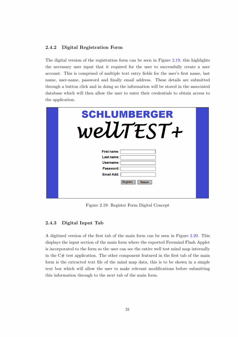
2.4.2 Digital Registration Form
The digital version of the registration form can be seen in Figure 2.19, this highlights
the necessary user input that it required for the user to successfully create a user
account. This is comprised of multiple text entry fields for the user’s first name, last
name, user-name, password and finally email address. These details are submitted
through a button click and in doing so the information will be stored in the associated
database which will then allow the user to enter their credentials to obtain access to
the application.
Figure 2.19: Register Form Digital Concept
2.4.3 Digital Input Tab
A digitised version of the first tab of the main form can be seen in Figure 2.20. This
displays the input section of the main form where the exported Freemind Flash Applet
is incorporated to the form so the user can see the entire well test mind map internally
in the C# test application. The other component featured in the first tab of the main
form is the extracted text file of the mind map data, this is to be shown in a simple
text box which will allow the user to make relevant modifications before submitting
this information through to the next tab of the main form.
31
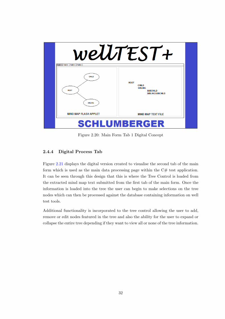
Figure 2.20: Main Form Tab 1 Digital Concept
2.4.4 Digital Process Tab
Figure 2.21 displays the digital version created to visualise the second tab of the main
form which is used as the main data processing page within the C# test application.
It can be seen through this design that this is where the Tree Control is loaded from
the extracted mind map text submitted from the first tab of the main form. Once the
information is loaded into the tree the user can begin to make selections on the tree
nodes which can then be processed against the database containing information on well
test tools.
Additional functionality is incorporated to the tree control allowing the user to add,
remove or edit nodes featured in the tree and also the ability for the user to expand or
collapse the entire tree depending if they want to view all or none of the tree information.
32
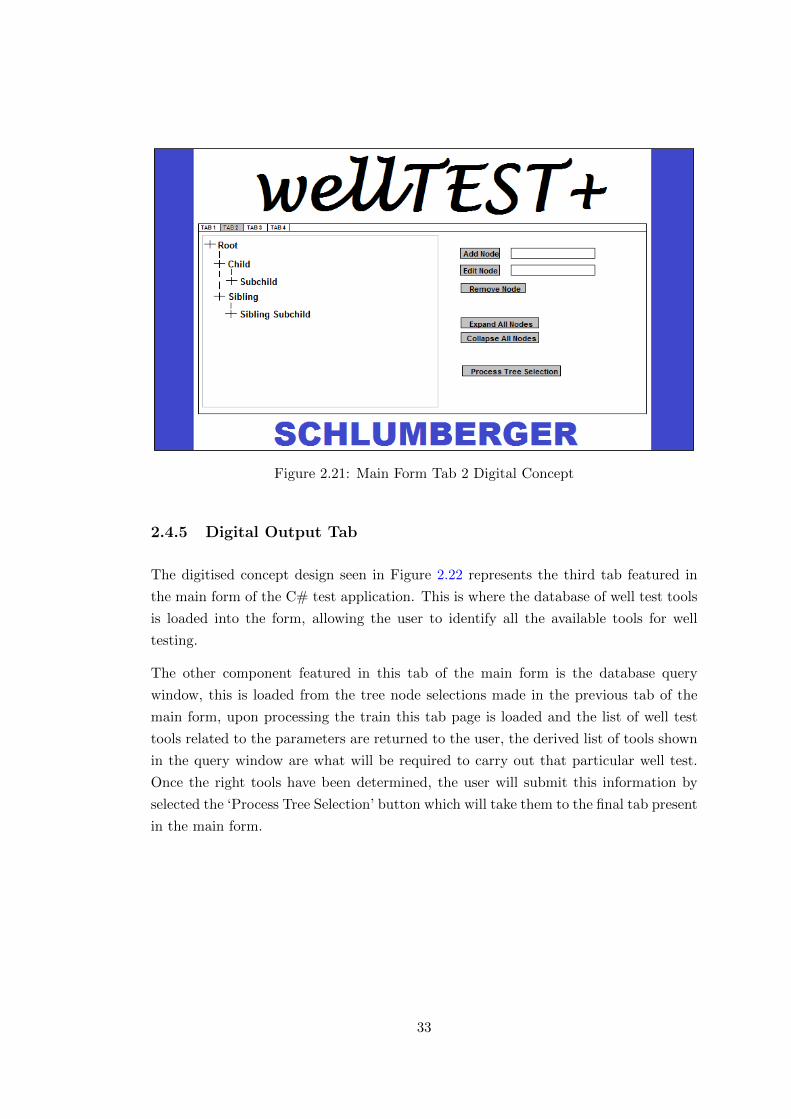
Figure 2.21: Main Form Tab 2 Digital Concept
2.4.5 Digital Output Tab
The digitised concept design seen in Figure 2.22 represents the third tab featured in
the main form of the C# test application. This is where the database of well test tools
is loaded into the form, allowing the user to identify all the available tools for well
testing.
The other component featured in this tab of the main form is the database query
window, this is loaded from the tree node selections made in the previous tab of the
main form, upon processing the train this tab page is loaded and the list of well test
tools related to the parameters are returned to the user, the derived list of tools shown
in the query window are what will be required to carry out that particular well test.
Once the right tools have been determined, the user will submit this information by
selected the ‘Process Tree Selection’ button which will take them to the final tab present
in the main form.
33
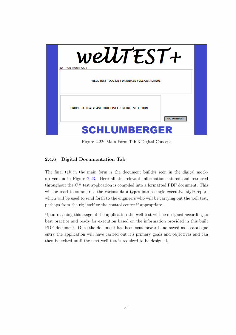
Figure 2.22: Main Form Tab 3 Digital Concept
2.4.6 Digital Documentation Tab
The final tab in the main form is the document builder seen in the digital mock-
up version in Figure 2.23. Here all the relevant information entered and retrieved
throughout the C# test application is compiled into a formatted PDF document. This
will be used to summarise the various data types into a single executive style report
which will be used to send forth to the engineers who will be carrying out the well test,
perhaps from the rig itself or the control centre if appropriate.
Upon reaching this stage of the application the well test will be designed according to
best practice and ready for execution based on the information provided in this built
PDF document. Once the document has been sent forward and saved as a catalogue
entry the application will have carried out it’s primary goals and objectives and can
then be exited until the next well test is required to be designed.
34
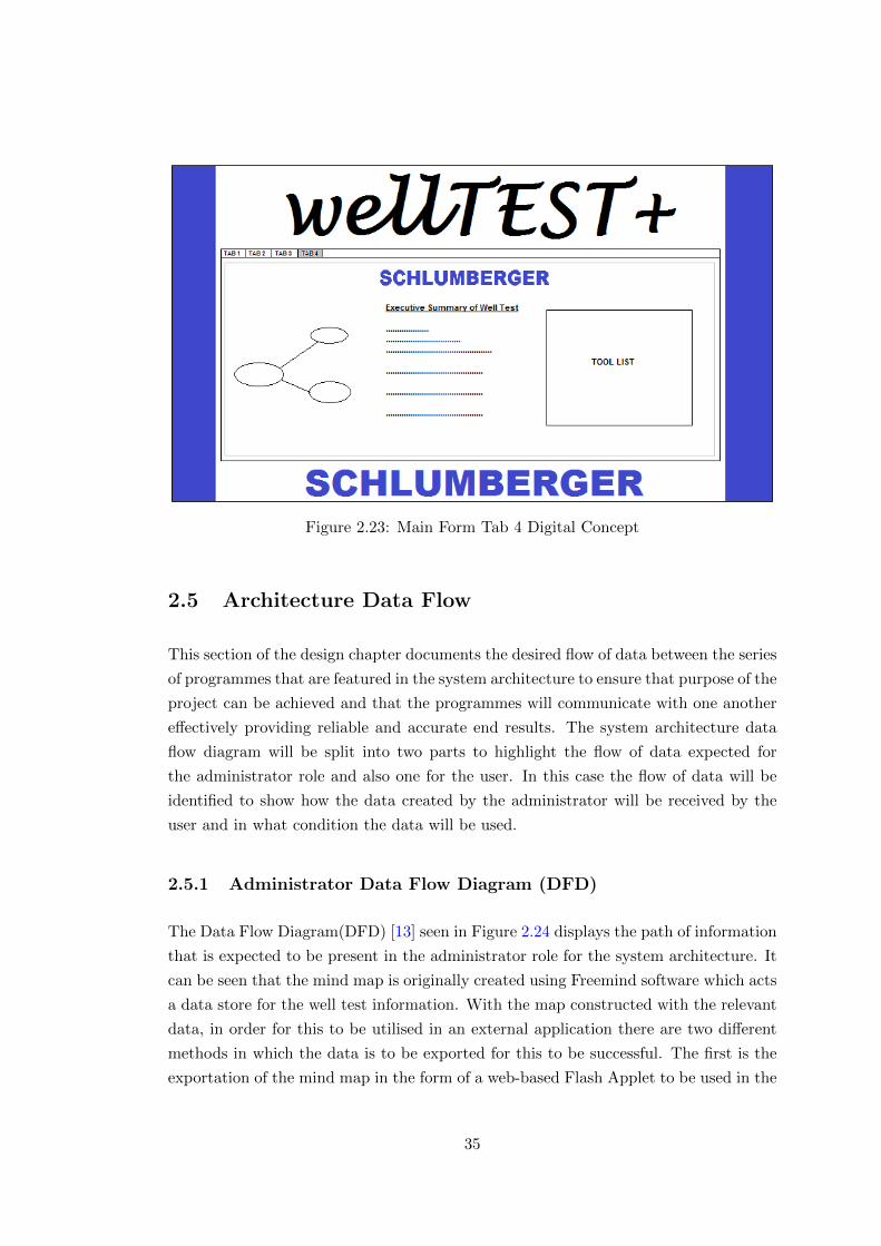
Figure 2.23: Main Form Tab 4 Digital Concept
2.5 Architecture Data Flow
This section of the design chapter documents the desired flow of data between the series
of programmes that are featured in the system architecture to ensure that purpose of the
project can be achieved and that the programmes will communicate with one another
effectively providing reliable and accurate end results. The system architecture data
flow diagram will be split into two parts to highlight the flow of data expected for
the administrator role and also one for the user. In this case the flow of data will be
identified to show how the data created by the administrator will be received by the
user and in what condition the data will be used.
2.5.1 Administrator Data Flow Diagram (DFD)
The Data Flow Diagram(DFD) [13] seen in Figure 2.24 displays the path of information
that is expected to be present in the administrator role for the system architecture. It
can be seen that the mind map is originally created using Freemind software which acts
a data store for the well test information. With the map constructed with the relevant
data, in order for this to be utilised in an external application there are two different
methods in which the data is to be exported for this to be successful. The first is the
exportation of the mind map in the form of a web-based Flash Applet to be used in the
35
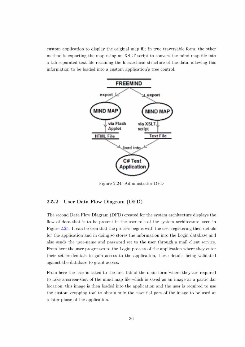
custom application to display the original map file in true traversable form, the other
method is exporting the map using an XSLT script to convert the mind map file into
a tab separated text file retaining the hierarchical structure of the data, allowing this
information to be loaded into a custom application’s tree control.
Figure 2.24: Administrator DFD
2.5.2 User Data Flow Diagram (DFD)
The second Data Flow Diagram (DFD) created for the system architecture displays the
flow of data that is to be present in the user role of the system architecture, seen in
Figure 2.25. It can be seen that the process begins with the user registering their details
for the application and in doing so stores the information into the Login database and
also sends the user-name and password set to the user through a mail client service.
From here the user progresses to the Login process of the application where they enter
their set credentials to gain access to the application, these details being validated
against the database to grant access.
From here the user is taken to the first tab of the main form where they are required
to take a screen-shot of the mind map file which is saved as an image at a particular
location, this image is then loaded into the application and the user is required to use
the custom cropping tool to obtain only the essential part of the image to be used at
a later phase of the application.
36
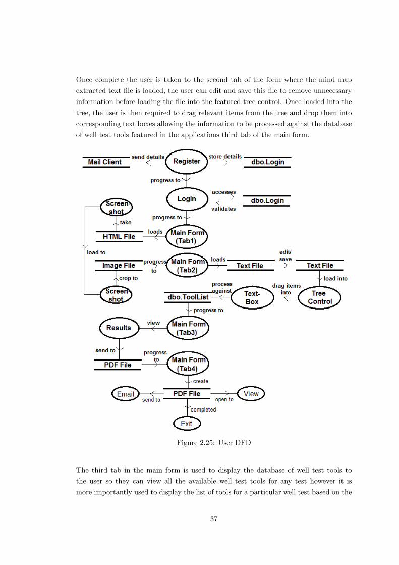
Once complete the user is taken to the second tab of the form where the mind map
extracted text file is loaded, the user can edit and save this file to remove unnecessary
information before loading the file into the featured tree control. Once loaded into the
tree, the user is then required to drag relevant items from the tree and drop them into
corresponding text boxes allowing the information to be processed against the database
of well test tools featured in the applications third tab of the main form.
Figure 2.25: User DFD
The third tab in the main form is used to display the database of well test tools to
the user so they can view all the available well test tools for any test however it is
more importantly used to display the list of tools for a particular well test based on the
37
information provided in the previous form. Alongside this the user has the capability
to add and remove items to the entire tool database and to also save these changes
after modifications have been made.
These details then get passed to the final tab of the main form where the user can
create a PDF document containing all the important information featured throughout
the application. The user can also view and email the document within the application
removing the necessity for a third party document viewer/mail client. Once completed,
the application has performed all the necessary tasks so therefore can be exited by the
user.
2.6 Conclusions
With a mind map produced in Freemind acting as the first major component in the
architecture, and used to store important well test knowledge, it was essential to ensure
that it was designed in such a way that all the information was contained within a
single map file. This allowed all the data from the map to be successfully captured and
exported to the next architecture component using a suitable format.
The main component of the system architecture was designed to allow processing of
the exported mind map data using a variety of technologies to achieve the main tasks
of designing, executing and interpreting a well test. This consisted of an application
created using C# to fit in line with Schlumberger’s current development language that
was comprised of a login form to allow access to the application, registration form
to allow user’s to create an account and finally a main form which incorporates the
relevant technologies to manipulate the mind map data to produce results for planning
a well test.
The final component of the architecture was designed to accommodate the data that
was to be stored and accessed using the main component. This consisted of an SQL
database which contained two tables to hold this information; a Login table and a Tool
List table. Between these two tables all relevant user details could be handled and also
the tools that are available for well tests could be stored and accessed upon request
from the system architecture’s main component.
It can be concluded from the design chapter that the way in which the system archi-
tecture was designed significantly impacted how the data flowed through each of the
components and also how the structure of the architecture was implemented.
38
Chapter 3
Implementation
This chapter examines the various aspects of implementation that were undertaken
for the project. This covers the development of the external mind map application
and details the relevance it has in providing data for the other elements featured in
the system architecture. Alongside the implementation of the mind map for the sys-
tem architecture, this chapter also details the incorporation of the back-end database
which is used to hold and query information that will be featured in the C# test ap-
plication. The incorporation of the C# test application is the main component in the
system architecture therefore this project focuses primarily on the implementation of
this application.
Through all these components the entire implementation process of the system architec-
ture will be documented showing the final outcome of development whilst also detailing
the issues that arose during this phase and how the solutions were applied to rectify
these problems.
3.1 Well Test Data
The data seen previously in this document comprised of oil and gas related terms
which in actuality has little impacting relevance towards the design, execution and
interpretation of well tests. This was mainly used as a means of demonstrating the
structure of the various architecture’s components and how data would presented in
these formats. As a result of this, the following chapter makes use of relevant well test
data that would determine the outcome of a well test taking into account the main
parameters and conditions that would affect the design, execution and interpretation
of a well test.
39

The practice of well testing encompasses a vast amount of relevant information, all of
which has a consequential effect on the tools that would be required to perform the
test, ensuring it was undertaken safely using appropriate tools to handle the present
conditions of the well. Due to this, a simple string of information was used from a
Piping and Instrumentation Diagram (P&ID) to capture the main factors that need
to be considered when designing a test [14]. This consisted of four main parameters;
Flowrate mmscfd (standard cubic feet per day), Pressure psi (pounds per square inch),
Temperature F (degrees Fahrenheit) and Fluid Type (oil or gas).
For each of these parameters, a range of conditions were implemented to ensure that
when performing the well test, realistic selections could be made to account for the
potential characteristics of the well. To accommodate these conditions, an associated
list of well test tools was implemented which also incorporated these conditions into a
criteria field, which would ultimately determine which tool was best suited towards the
conditions of the related well test design parameter.
With this data in place, the architecture could make use of relevant well test data which
allowed for a realistic and effective method to design, execute and interpret a well test.
3.2 Mind Map Implementation
Using extensive component design and developmental testing during the project inves-
tigation, with the addition of the design decisions made during the project implemen-
tation, the most suitable and effective method for incorporating external mind maps
into the system architecture was derived. Due to it’s cross-platform compatibility and
adapt set of features in comparison to other mind map software packages, Freemind was
the most effective choice to be used in the system architecture as it stores and exports
the data needed for other components in the architecture in a suitable format.[15]
3.2.1 Creating the Mind Map
It was established that the most prominent method for exchanging data between the
mind map package and the custom developed C# test application was to create the
mind map in a single map document file, as opposed to an internally linked series of
map document files. With this method being the most viable it also minimises the dif-
ficulty in organising and creating the actual mind map file resulting in an advantageous
implementation method.
40
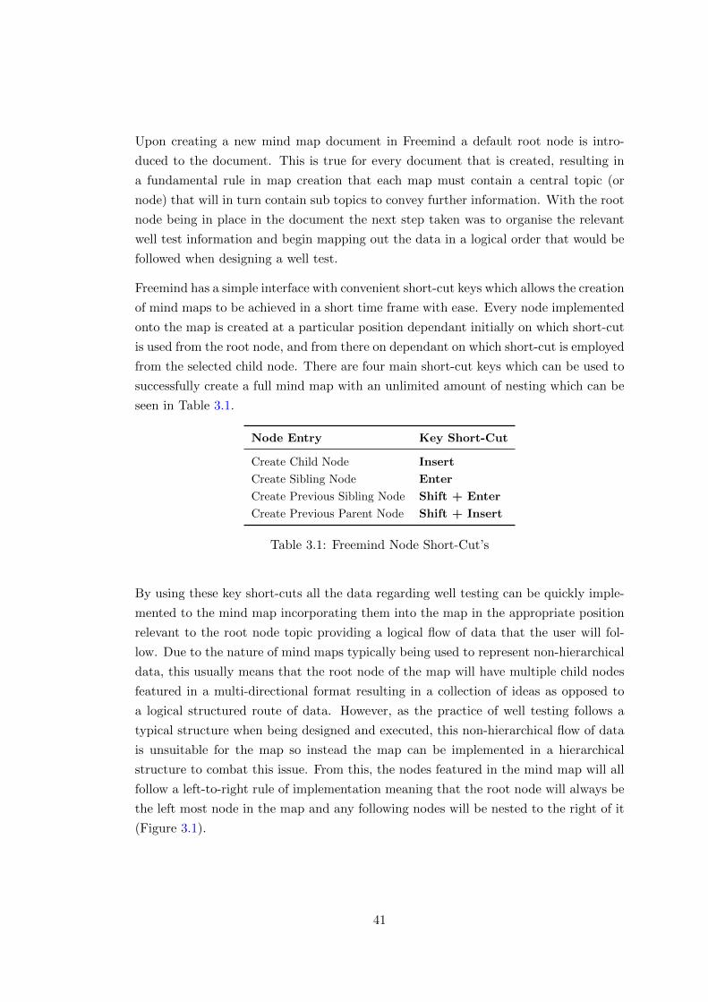
Upon creating a new mind map document in Freemind a default root node is intro-
duced to the document. This is true for every document that is created, resulting in
a fundamental rule in map creation that each map must contain a central topic (or
node) that will in turn contain sub topics to convey further information. With the root
node being in place in the document the next step taken was to organise the relevant
well test information and begin mapping out the data in a logical order that would be
followed when designing a well test.
Freemind has a simple interface with convenient short-cut keys which allows the creation
of mind maps to be achieved in a short time frame with ease. Every node implemented
onto the map is created at a particular position dependant initially on which short-cut
is used from the root node, and from there on dependant on which short-cut is employed
from the selected child node. There are four main short-cut keys which can be used to
successfully create a full mind map with an unlimited amount of nesting which can be
seen in Table 3.1.
Node Entry Key Short-Cut
Create Child Node Insert
Create Sibling Node Enter
Create Previous Sibling Node Shift + Enter
Create Previous Parent Node Shift + Insert
Table 3.1: Freemind Node Short-Cut’s
By using these key short-cuts all the data regarding well testing can be quickly imple-
mented to the mind map incorporating them into the map in the appropriate position
relevant to the root node topic providing a logical flow of data that the user will fol-
low. Due to the nature of mind maps typically being used to represent non-hierarchical
data, this usually means that the root node of the map will have multiple child nodes
featured in a multi-directional format resulting in a collection of ideas as opposed to
a logical structured route of data. However, as the practice of well testing follows a
typical structure when being designed and executed, this non-hierarchical flow of data
is unsuitable for the map so instead the map can be implemented in a hierarchical
structure to combat this issue. From this, the nodes featured in the mind map will all
follow a left-to-right rule of implementation meaning that the root node will always be
the left most node in the map and any following nodes will be nested to the right of it
(Figure 3.1).
41
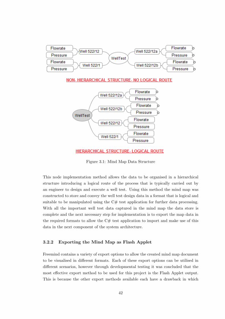
Figure 3.1: Mind Map Data Structure
This node implementation method allows the data to be organised in a hierarchical
structure introducing a logical route of the process that is typically carried out by
an engineer to design and execute a well test. Using this method the mind map was
constructed to store and convey the well test design data in a format that is logical and
suitable to be manipulated using the C# test application for further data processing.
With all the important well test data captured in the mind map the data store is
complete and the next necessary step for implementation is to export the map data in
the required formats to allow the C# test application to import and make use of this
data in the next component of the system architecture.
3.2.2 Exporting the Mind Map as Flash Applet
Freemind contains a variety of export options to allow the created mind map document
to be visualised in different formats. Each of these export options can be utilised in
different scenarios, however through developmental testing it was concluded that the
most effective export method to be used for this project is the Flash Applet output.
This is because the other export methods available each have a drawback in which
42
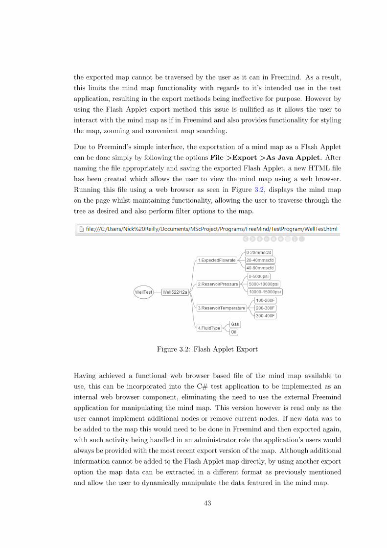
the exported map cannot be traversed by the user as it can in Freemind. As a result,
this limits the mind map functionality with regards to it’s intended use in the test
application, resulting in the export methods being ineffective for purpose. However by
using the Flash Applet export method this issue is nullified as it allows the user to
interact with the mind map as if in Freemind and also provides functionality for styling
the map, zooming and convenient map searching.
Due to Freemind’s simple interface, the exportation of a mind map as a Flash Applet
can be done simply by following the options File >Export >As Java Applet. After
naming the file appropriately and saving the exported Flash Applet, a new HTML file
has been created which allows the user to view the mind map using a web browser.
Running this file using a web browser as seen in Figure 3.2, displays the mind map
on the page whilst maintaining functionality, allowing the user to traverse through the
tree as desired and also perform filter options to the map.
Figure 3.2: Flash Applet Export
Having achieved a functional web browser based file of the mind map available to
use, this can be incorporated into the C# test application to be implemented as an
internal web browser component, eliminating the need to use the external Freemind
application for manipulating the mind map. This version however is read only as the
user cannot implement additional nodes or remove current nodes. If new data was to
be added to the map this would need to be done in Freemind and then exported again,
with such activity being handled in an administrator role the application’s users would
always be provided with the most recent export version of the map. Although additional
information cannot be added to the Flash Applet map directly, by using another export
option the map data can be extracted in a different format as previously mentioned
and allow the user to dynamically manipulate the data featured in the mind map.
43

3.2.3 Exporting the Mind Map as Text File
Another useful export option that Freemind contains is turning the mind map data
into a text-based format. There are two primary methods to achieve this in Freemind
and both versions were tested in the C# application to investigate the advantages and
disadvantages of each method.
The first method used to extract the map data into text format uses the eXtensible
Systelsheet Language Transformation (XSLT) export option. This is achieved by fol-
lowing the options File >Export >Using XSLT and from here the users will be
taken to a window which requires a new file name to be entered and a location to be
specified to save the exported file. Parallel to this there is always an option to load up
the XSLT file that will be used to convert the mind map. There are a variety of XSLT
scripts available for Freemind, found at http://http://freemind.sourceforge.net/
wiki/index.php/Import_and_export, however the one which was used converts the
map data into a Comma Separated Value (CSV) file.
Figure 3.3: XSLT Export
It can be shown in Figure 3.3 that by using this script the mind map is converted into
a text file representation of the data that identifies the levels of nesting according to
the root node (no comma) by having a number of commas preceding the text value.
This clearly identifies at which level each piece of data is featured in the mind map
and allows for comparisons to be made about the relation of nodes in the map and how
they are structured. The data format obtained from using the XSLT script provides a
usable data format to allow this information to be used in the C# test application and
to be further manipulated and used to load into a tree control for essential processing.
44
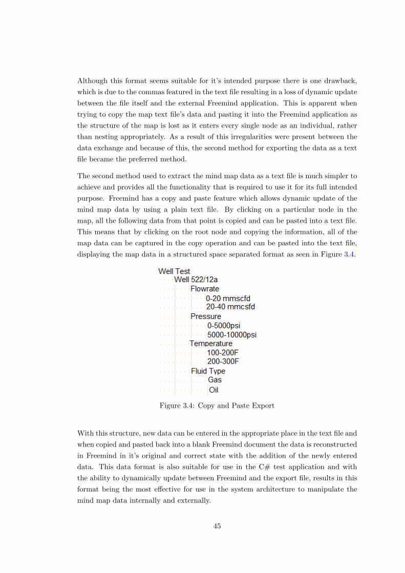
Although this format seems suitable for it’s intended purpose there is one drawback,
which is due to the commas featured in the text file resulting in a loss of dynamic update
between the file itself and the external Freemind application. This is apparent when
trying to copy the map text file’s data and pasting it into the Freemind application as
the structure of the map is lost as it enters every single node as an individual, rather
than nesting appropriately. As a result of this irregularities were present between the
data exchange and because of this, the second method for exporting the data as a text
file became the preferred method.
The second method used to extract the mind map data as a text file is much simpler to
achieve and provides all the functionality that is required to use it for its full intended
purpose. Freemind has a copy and paste feature which allows dynamic update of the
mind map data by using a plain text file. By clicking on a particular node in the
map, all the following data from that point is copied and can be pasted into a text file.
This means that by clicking on the root node and copying the information, all of the
map data can be captured in the copy operation and can be pasted into the text file,
displaying the map data in a structured space separated format as seen in Figure 3.4.
Figure 3.4: Copy and Paste Export
With this structure, new data can be entered in the appropriate place in the text file and
when copied and pasted back into a blank Freemind document the data is reconstructed
in Freemind in it’s original and correct state with the addition of the newly entered
data. This data format is also suitable for use in the C# test application and with
the ability to dynamically update between Freemind and the export file, results in this
format being the most effective for use in the system architecture to manipulate the
mind map data internally and externally.
45
With all the relevant data exportation methods applied, the first component of the
system architecture is complete and handles the data that is needed to be passed to
the main component of the architecture, the C# test application. Before the main
component of the architecture was developed, a back-end database was required to be
implemented to also act as a data store for the information that is specific to the C#
application itself.
3.3 Database Implementation
As with many computer systems, having a back-end database is an essential requirement
to store and access data that is commonly featured throughout a program. For this
system architecture a database was required to store two tables that will contain the
relevant information to serve the goals of the architecture’s main component, the C#
test application.
There are a variety of languages available for the creation and querying of databases
and alongside this there are also a multitude of management studios available to handle
all the database functionality that is required for implementation. For the system
architecture, the Structured Query Language (SQL) was chosen as it is one of the most
widely used query languages for databases and is highly supported across a variety of
platforms and systems [7]. To accompany the choice of language used to script the
creation of databases and tables, SQL Server Management Studio 2012 was utilised to
handle the database entries and from within the program this can make modifications
to the featured data. By using this program, a local server is created with two options
for authentication for increased security. It supports Windows authentication and
also MySQL authentication, resulting in a more secure server to prevent unauthorised
access. Another advantage of SQL Server Management Studio is that by creating a
local server holding the database information, this contains a connection string which
can be accessed in the external C# test application, providing communication between
components of the system architecture allowing important information to be stored and
accessed on request.
As previously mentioned, the system architecture requires the creation of two tables
in the database to ensure that the necessary information will be stored and can be
accessed; a table for the user’s details and another one for well test tools.
46
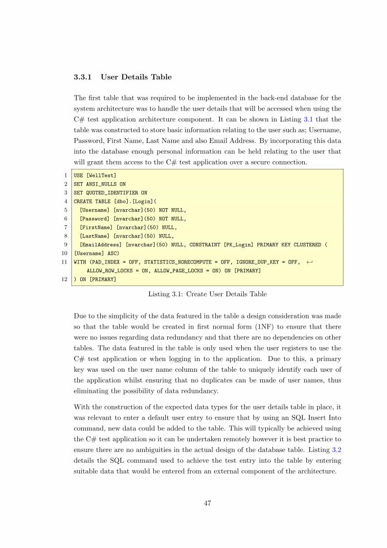
3.3.1 User Details Table
The first table that was required to be implemented in the back-end database for the
system architecture was to handle the user details that will be accessed when using the
C# test application architecture component. It can be shown in Listing 3.1 that the
table was constructed to store basic information relating to the user such as; Username,
Password, First Name, Last Name and also Email Address. By incorporating this data
into the database enough personal information can be held relating to the user that
will grant them access to the C# test application over a secure connection.
1 USE [WellTest]
2 SET ANSI_NULLS ON
3 SET QUOTED_IDENTIFIER ON
4 CREATE TABLE [dbo].[Login](
5 [Username] [nvarchar](50) NOT NULL,
6 [Password] [nvarchar](50) NOT NULL,
7 [FirstName] [nvarchar](50) NULL,
8 [LastName] [nvarchar](50) NULL,
9 [EmailAddress] [nvarchar](50) NULL, CONSTRAINT [PK_Login] PRIMARY KEY CLUSTERED (
10 [Username] ASC)
11 WITH (PAD_INDEX = OFF, STATISTICS_NORECOMPUTE = OFF, IGNORE_DUP_KEY = OFF, ←↩ALLOW_ROW_LOCKS = ON, ALLOW_PAGE_LOCKS = ON) ON [PRIMARY]
12 ) ON [PRIMARY]
Listing 3.1: Create User Details Table
Due to the simplicity of the data featured in the table a design consideration was made
so that the table would be created in first normal form (1NF) to ensure that there
were no issues regarding data redundancy and that there are no dependencies on other
tables. The data featured in the table is only used when the user registers to use the
C# test application or when logging in to the application. Due to this, a primary
key was used on the user name column of the table to uniquely identify each user of
the application whilst ensuring that no duplicates can be made of user names, thus
eliminating the possibility of data redundancy.
With the construction of the expected data types for the user details table in place, it
was relevant to enter a default user entry to ensure that by using an SQL Insert Into
command, new data could be added to the table. This will typically be achieved using
the C# test application so it can be undertaken remotely however it is best practice to
ensure there are no ambiguities in the actual design of the database table. Listing 3.2
details the SQL command used to achieve the test entry into the table by entering
suitable data that would be entered from an external component of the architecture.
47
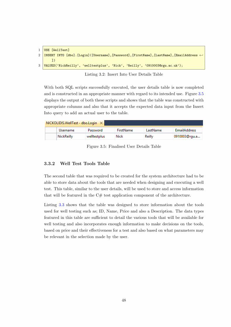
1 USE [WellTest]
2 INSERT INTO [dbo].[Login]([Username],[Password],[FirstName],[LastName],[EmailAddress ←↩])
3 VALUES(’NickReilly’, ’welltestplus’, ’Nick’, ’Reilly’, ’[email protected]’);
Listing 3.2: Insert Into User Details Table
With both SQL scripts successfully executed, the user details table is now completed
and is constructed in an appropriate manner with regard to its intended use. Figure 3.5
displays the output of both these scripts and shows that the table was constructed with
appropriate columns and also that it accepts the expected data input from the Insert
Into query to add an actual user to the table.
Figure 3.5: Finalised User Details Table
3.3.2 Well Test Tools Table
The second table that was required to be created for the system architecture had to be
able to store data about the tools that are needed when designing and executing a well
test. This table, similar to the user details, will be used to store and access information
that will be featured in the C# test application component of the architecture.
Listing 3.3 shows that the table was designed to store information about the tools
used for well testing such as; ID, Name, Price and also a Description. The data types
featured in this table are sufficient to detail the various tools that will be available for
well testing and also incorporates enough information to make decisions on the tools,
based on price and their effectiveness for a test and also based on what parameters may
be relevant in the selection made by the user.
48
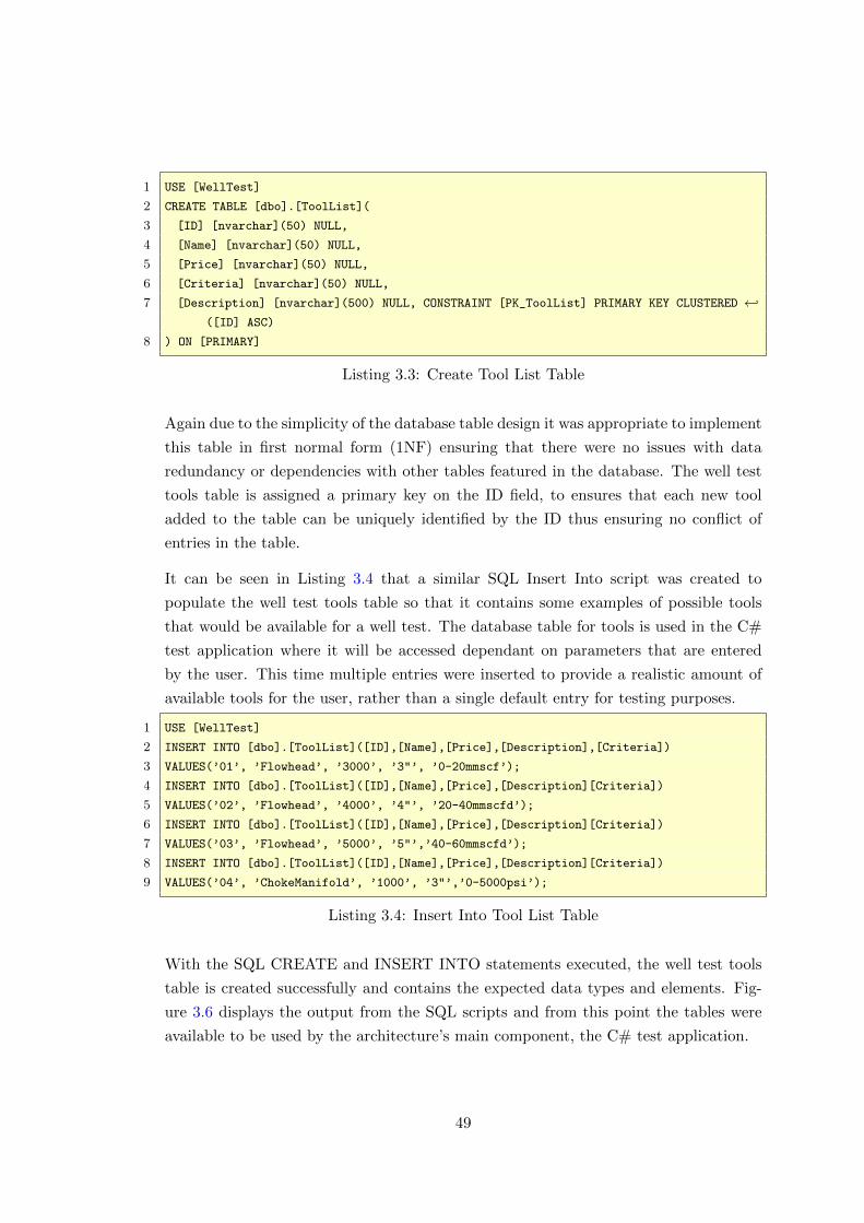
1 USE [WellTest]
2 CREATE TABLE [dbo].[ToolList](
3 [ID] [nvarchar](50) NULL,
4 [Name] [nvarchar](50) NULL,
5 [Price] [nvarchar](50) NULL,
6 [Criteria] [nvarchar](50) NULL,
7 [Description] [nvarchar](500) NULL, CONSTRAINT [PK_ToolList] PRIMARY KEY CLUSTERED ←↩([ID] ASC)
8 ) ON [PRIMARY]
Listing 3.3: Create Tool List Table
Again due to the simplicity of the database table design it was appropriate to implement
this table in first normal form (1NF) ensuring that there were no issues with data
redundancy or dependencies with other tables featured in the database. The well test
tools table is assigned a primary key on the ID field, to ensures that each new tool
added to the table can be uniquely identified by the ID thus ensuring no conflict of
entries in the table.
It can be seen in Listing 3.4 that a similar SQL Insert Into script was created to
populate the well test tools table so that it contains some examples of possible tools
that would be available for a well test. The database table for tools is used in the C#
test application where it will be accessed dependant on parameters that are entered
by the user. This time multiple entries were inserted to provide a realistic amount of
available tools for the user, rather than a single default entry for testing purposes.
1 USE [WellTest]
2 INSERT INTO [dbo].[ToolList]([ID],[Name],[Price],[Description],[Criteria])
3 VALUES(’01’, ’Flowhead’, ’3000’, ’3"’, ’0-20mmscf’);
4 INSERT INTO [dbo].[ToolList]([ID],[Name],[Price],[Description][Criteria])
5 VALUES(’02’, ’Flowhead’, ’4000’, ’4"’, ’20-40mmscfd’);
6 INSERT INTO [dbo].[ToolList]([ID],[Name],[Price],[Description][Criteria])
7 VALUES(’03’, ’Flowhead’, ’5000’, ’5"’,’40-60mmscfd’);
8 INSERT INTO [dbo].[ToolList]([ID],[Name],[Price],[Description][Criteria])
9 VALUES(’04’, ’ChokeManifold’, ’1000’, ’3"’,’0-5000psi’);
Listing 3.4: Insert Into Tool List Table
With the SQL CREATE and INSERT INTO statements executed, the well test tools
table is created successfully and contains the expected data types and elements. Fig-
ure 3.6 displays the output from the SQL scripts and from this point the tables were
available to be used by the architecture’s main component, the C# test application.
49

Figure 3.6: Finalised Well Test Tool Table
At this point of the development stage in the project implementation, both data store
components of the system architecture were in place holding the relevant data for
access by the main component of the architecture. The next stage required to be
undertaken was the actual implementation of the C# test application to prove that the
architecture performs efficiently and to ensure that each component in the architecture
can communicate with one another to provide the expected output results.
3.4 C# GUI Development Set-up
The following section of the project implementation report details the development
that was undertaken to create the main component of the system architecture, the
C# test application. This section entails the majority of the developmental tasks that
were performed as this is the component that is operated by the user to communicate
with the other components in the architecture to achieve the task of designing and
executing a well test. The test application was chosen to be developed using the
C# .NET framework as this is what Schlumberger use to develop their solutions, so
a design consideration was made to implement this solution in accordance with the
current standards used by Schlumberger.
This section of the report will detail the entire developmental process of the C# ap-
plication from the initial set-up of the application, to each of the components that are
featured in it whilst covering any problems that arose during this process and how they
were rectified.
3.4.1 Form Initialisation
The first task that was required to be carried out when developing the C# test ap-
plication was the initial set-up of the application itself. C# is an extensive language
that can developed using a multitude of programs and also can be implemented as
50
different versions of the C# language [16]. For this project it was decided that the
C# application would be developed as a Windows Forms Application using Microsoft
Visual Studio 2013 as this is a highly supported development style which has access to
a library of useful components for creating applications.
To create a Windows Forms Application in Microsoft Visual Studio 2013 a new project
is started by selecting the Windows Forms Application option. Upon choosing a relevant
directory and entering a valid name for the project, a new Windows Forms Application
form is generated. This creates a default form which has no styling applied and is set
at a default size. It can be seen that the default form that was created features nothing
in it besides the actual form itself with the default size parameters and also a tool bar
which contains some controls for the form. The control’s provided by the initial form
set up contain buttons to allow the user to minimise the form, maximise/restore the
form and also to close the form. Alongside this the borders of the form can actually be
adjusted by a simple click and drag operation of the relevant axis.
One of the advantages of developing C# Windows Forms Applications using Microsoft
Visual Studio 2013 is that it mixes development techniques to give greater flexibility in
the design and manipulation of forms. Components can be dragged and dropped into
the form and from this auto-generates the related code detailing the various parameters
that it holds. Although it auto-generates code it also produces a code file which can
be edited to modify these parameters and apply these changes directly to the form.
By modifying the code file, changes can be made to the form. An example of this was
modifying the code to change the default title applied to the form to show the new title
that was entered.
The form tool-bar provides all the essential controls that are required to adjust the
size of an application however the styling of this control cannot be modified as it is an
in-built C# component as part of Microsoft Visual Studio. It is commonplace when
developing an application to create custom controls so that styling can be applied to
match the intended look of the application itself.
3.4.2 Custom Form Handling Control
Due to the custom control component in Microsoft Visual Studio being a fixed style,
this did not align with the considered design for the application and in this respect there
was a need to implement a custom control for form handling. The default handling
control can be removed from the form by setting the FormBorderStyle = none and
this results in only the body of the form being displayed.
51
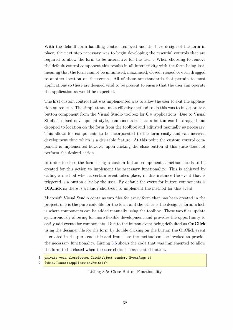
With the default form handling control removed and the base design of the form in
place, the next step necessary was to begin developing the essential controls that are
required to allow the form to be interactive for the user . When choosing to remove
the default control component this results in all interactivity with the form being lost,
meaning that the form cannot be minimised, maximised, closed, resized or even dragged
to another location on the screen. All of these are standards that pertain to most
applications so these are deemed vital to be present to ensure that the user can operate
the application as would be expected.
The first custom control that was implemented was to allow the user to exit the applica-
tion on request. The simplest and most effective method to do this was to incorporate a
button component from the Visual Studio toolbox for C# applications. Due to Visual
Studio’s mixed development style, components such as a button can be dragged and
dropped to location on the form from the toolbox and adjusted manually as necessary.
This allows for components to be incorporated to the form easily and can increase
development time which is a desirable feature. At this point the custom control com-
ponent is implemented however upon clicking the close button at this state does not
perform the desired action.
In order to close the form using a custom button component a method needs to be
created for this action to implement the necessary functionality. This is achieved by
calling a method when a certain event takes place, in this instance the event that is
triggered is a button click by the user. By default the event for button components is
OnClick so there is a handy short-cut to implement the method for this event.
Microsoft Visual Studio contains two files for every form that has been created in the
project, one is the pure code file for the form and the other is the designer form, which
is where components can be added manually using the toolbox. These two files update
synchronously allowing for more flexible development and provides the opportunity to
easily add events for components. Due to the button event being defaulted as OnClick
using the designer file for the form by double clicking on the button the OnClick event
is created in the pure code file and from here the method can be invoked to provide
the necessary functionality. Listing 3.5 shows the code that was implemented to allow
the form to be closed when the user clicks the associated button.
1 private void closeButton_Click(object sender, EventArgs e)
2 {this.Close();Application.Exit();}
Listing 3.5: Close Button Functionality
52
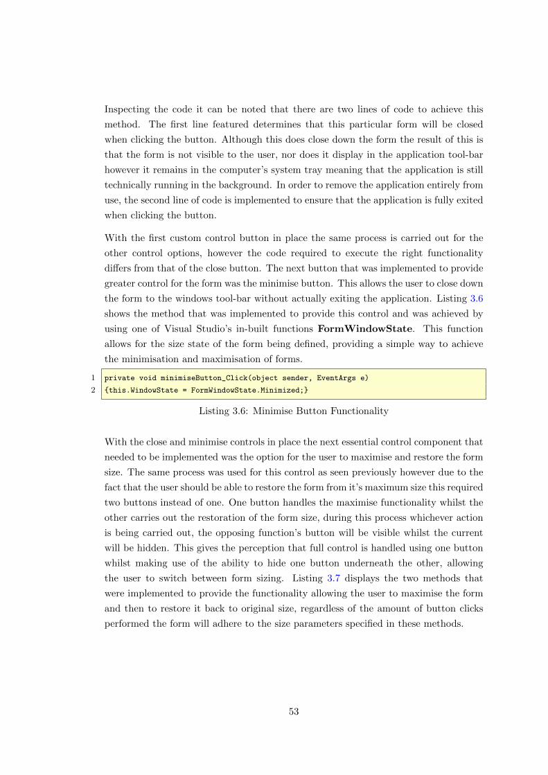
Inspecting the code it can be noted that there are two lines of code to achieve this
method. The first line featured determines that this particular form will be closed
when clicking the button. Although this does close down the form the result of this is
that the form is not visible to the user, nor does it display in the application tool-bar
however it remains in the computer’s system tray meaning that the application is still
technically running in the background. In order to remove the application entirely from
use, the second line of code is implemented to ensure that the application is fully exited
when clicking the button.
With the first custom control button in place the same process is carried out for the
other control options, however the code required to execute the right functionality
differs from that of the close button. The next button that was implemented to provide
greater control for the form was the minimise button. This allows the user to close down
the form to the windows tool-bar without actually exiting the application. Listing 3.6
shows the method that was implemented to provide this control and was achieved by
using one of Visual Studio’s in-built functions FormWindowState. This function
allows for the size state of the form being defined, providing a simple way to achieve
the minimisation and maximisation of forms.
1 private void minimiseButton_Click(object sender, EventArgs e)
2 {this.WindowState = FormWindowState.Minimized;}
Listing 3.6: Minimise Button Functionality
With the close and minimise controls in place the next essential control component that
needed to be implemented was the option for the user to maximise and restore the form
size. The same process was used for this control as seen previously however due to the
fact that the user should be able to restore the form from it’s maximum size this required
two buttons instead of one. One button handles the maximise functionality whilst the
other carries out the restoration of the form size, during this process whichever action
is being carried out, the opposing function’s button will be visible whilst the current
will be hidden. This gives the perception that full control is handled using one button
whilst making use of the ability to hide one button underneath the other, allowing
the user to switch between form sizing. Listing 3.7 displays the two methods that
were implemented to provide the functionality allowing the user to maximise the form
and then to restore it back to original size, regardless of the amount of button clicks
performed the form will adhere to the size parameters specified in these methods.
53
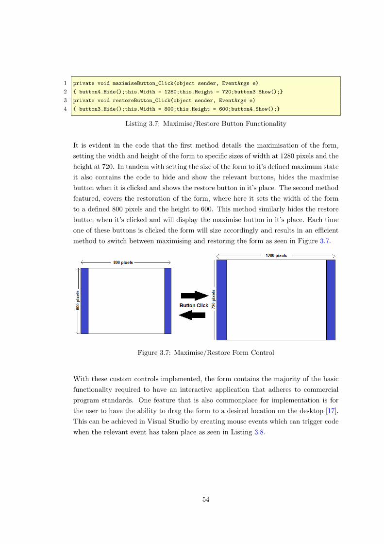
1 private void maximiseButton_Click(object sender, EventArgs e)
2 { button4.Hide();this.Width = 1280;this.Height = 720;button3.Show();}
3 private void restoreButton_Click(object sender, EventArgs e)
4 { button3.Hide();this.Width = 800;this.Height = 600;button4.Show();}
Listing 3.7: Maximise/Restore Button Functionality
It is evident in the code that the first method details the maximisation of the form,
setting the width and height of the form to specific sizes of width at 1280 pixels and the
height at 720. In tandem with setting the size of the form to it’s defined maximum state
it also contains the code to hide and show the relevant buttons, hides the maximise
button when it is clicked and shows the restore button in it’s place. The second method
featured, covers the restoration of the form, where here it sets the width of the form
to a defined 800 pixels and the height to 600. This method similarly hides the restore
button when it’s clicked and will display the maximise button in it’s place. Each time
one of these buttons is clicked the form will size accordingly and results in an efficient
method to switch between maximising and restoring the form as seen in Figure 3.7.
Figure 3.7: Maximise/Restore Form Control
With these custom controls implemented, the form contains the majority of the basic
functionality required to have an interactive application that adheres to commercial
program standards. One feature that is also commonplace for implementation is for
the user to have the ability to drag the form to a desired location on the desktop [17].
This can be achieved in Visual Studio by creating mouse events which can trigger code
when the relevant event has taken place as seen in Listing 3.8.
54
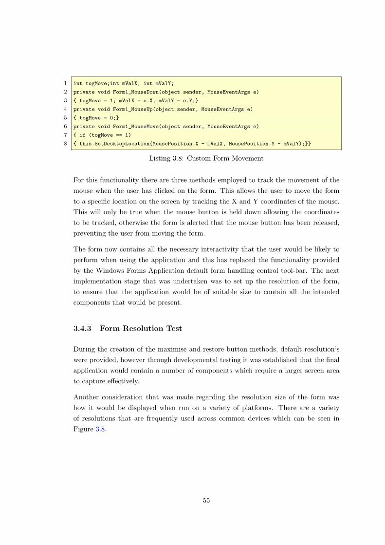
1 int togMove;int mValX; int mValY;
2 private void Form1_MouseDown(object sender, MouseEventArgs e)
3 { togMove = 1; mValX = e.X; mValY = e.Y;}
4 private void Form1_MouseUp(object sender, MouseEventArgs e)
5 { togMove = 0;}
6 private void Form1_MouseMove(object sender, MouseEventArgs e)
7 { if (togMove == 1)
8 { this.SetDesktopLocation(MousePosition.X - mValX, MousePosition.Y - mValY);}}
Listing 3.8: Custom Form Movement
For this functionality there are three methods employed to track the movement of the
mouse when the user has clicked on the form. This allows the user to move the form
to a specific location on the screen by tracking the X and Y coordinates of the mouse.
This will only be true when the mouse button is held down allowing the coordinates
to be tracked, otherwise the form is alerted that the mouse button has been released,
preventing the user from moving the form.
The form now contains all the necessary interactivity that the user would be likely to
perform when using the application and this has replaced the functionality provided
by the Windows Forms Application default form handling control tool-bar. The next
implementation stage that was undertaken was to set up the resolution of the form,
to ensure that the application would be of suitable size to contain all the intended
components that would be present.
3.4.3 Form Resolution Test
During the creation of the maximise and restore button methods, default resolution’s
were provided, however through developmental testing it was established that the final
application would contain a number of components which require a larger screen area
to capture effectively.
Another consideration that was made regarding the resolution size of the form was
how it would be displayed when run on a variety of platforms. There are a variety
of resolutions that are frequently used across common devices which can be seen in
Figure 3.8.
55
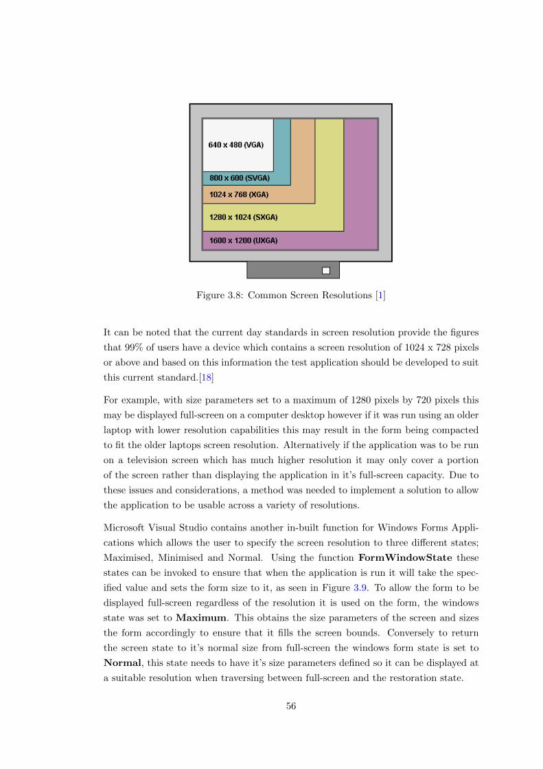
Figure 3.8: Common Screen Resolutions [1]
It can be noted that the current day standards in screen resolution provide the figures
that 99% of users have a device which contains a screen resolution of 1024 x 728 pixels
or above and based on this information the test application should be developed to suit
this current standard.[18]
For example, with size parameters set to a maximum of 1280 pixels by 720 pixels this
may be displayed full-screen on a computer desktop however if it was run using an older
laptop with lower resolution capabilities this may result in the form being compacted
to fit the older laptops screen resolution. Alternatively if the application was to be run
on a television screen which has much higher resolution it may only cover a portion
of the screen rather than displaying the application in it’s full-screen capacity. Due to
these issues and considerations, a method was needed to implement a solution to allow
the application to be usable across a variety of resolutions.
Microsoft Visual Studio contains another in-built function for Windows Forms Appli-
cations which allows the user to specify the screen resolution to three different states;
Maximised, Minimised and Normal. Using the function FormWindowState these
states can be invoked to ensure that when the application is run it will take the spec-
ified value and sets the form size to it, as seen in Figure 3.9. To allow the form to be
displayed full-screen regardless of the resolution it is used on the form, the windows
state was set to Maximum. This obtains the size parameters of the screen and sizes
the form accordingly to ensure that it fills the screen bounds. Conversely to return
the screen state to it’s normal size from full-screen the windows form state is set to
Normal, this state needs to have it’s size parameters defined so it can be displayed at
a suitable resolution when traversing between full-screen and the restoration state.
56
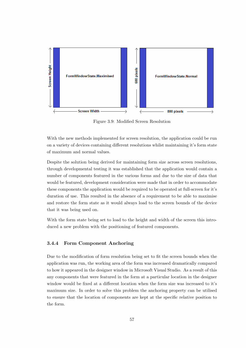
Figure 3.9: Modified Screen Resolution
With the new methods implemented for screen resolution, the application could be run
on a variety of devices containing different resolutions whilst maintaining it’s form state
of maximum and normal values.
Despite the solution being derived for maintaining form size across screen resolutions,
through developmental testing it was established that the application would contain a
number of components featured in the various forms and due to the size of data that
would be featured, development consideration were made that in order to accommodate
these components the application would be required to be operated at full-screen for it’s
duration of use. This resulted in the absence of a requirement to be able to maximise
and restore the form state as it would always load to the screen bounds of the device
that it was being used on.
With the form state being set to load to the height and width of the screen this intro-
duced a new problem with the positioning of featured components.
3.4.4 Form Component Anchoring
Due to the modification of form resolution being set to fit the screen bounds when the
application was run, the working area of the form was increased dramatically compared
to how it appeared in the designer window in Microsoft Visual Studio. As a result of this
any components that were featured in the form at a particular location in the designer
window would be fixed at a different location when the form size was increased to it’s
maximum size. In order to solve this problem the anchoring property can be utilised
to ensure that the location of components are kept at the specific relative position to
the form.
57
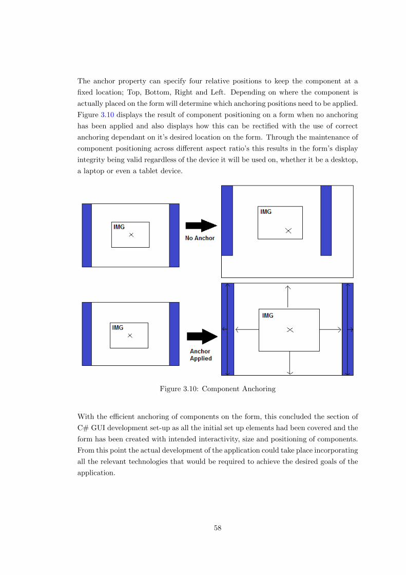
The anchor property can specify four relative positions to keep the component at a
fixed location; Top, Bottom, Right and Left. Depending on where the component is
actually placed on the form will determine which anchoring positions need to be applied.
Figure 3.10 displays the result of component positioning on a form when no anchoring
has been applied and also displays how this can be rectified with the use of correct
anchoring dependant on it’s desired location on the form. Through the maintenance of
component positioning across different aspect ratio’s this results in the form’s display
integrity being valid regardless of the device it will be used on, whether it be a desktop,
a laptop or even a tablet device.
Figure 3.10: Component Anchoring
With the efficient anchoring of components on the form, this concluded the section of
C# GUI development set-up as all the initial set up elements had been covered and the
form has been created with intended interactivity, size and positioning of components.
From this point the actual development of the application could take place incorporating
all the relevant technologies that would be required to achieve the desired goals of the
application.
58

3.5 C# Registration Form
The beginning stage of most applications is to handle the user logging in and being
allowed access to the program. Before the user can login to the application they must
first register an account to contain their personal information and to provide credentials
that will allow the user to gain access to the application’s main page. In order to do
this the first appropriate form that needs to be implemented is a registration form.
As this is the first form of the application it was necessary to enhance the style of the
form to fit in line with Schlumberger’s current products and also to define the name of
the application so there is no user ambiguity with regards to what the program relates
to. The colour scheme implemented for the application replicates the colour’s used by
Schlumberger to easily identify that the application is one of their products. The subtle
use of the Pantone blue against the white background provides a simple yet effective
design for the application as it does not overburden the interface with a convoluted
work space, instead the main area of the application is easily identifiable to the user
resulting in an efficient choice of design.
With the colour scheme of the application set, the next element to incorporate was the
title and other necessary logo’s that the form should have. Due to the application’s main
purpose being to design and execute well tests, the name wellTEST+ was created to
act as the program’s title. This was chosen as it instantly reinforces the notion that
the content of the application will involve well testing. The logo for this was created
using Adobe Photoshop and also followed the colour scheme used by Schlumberger to
maintain consistency of design throughout the application. Figure 3.11 displays the
created logo for the application which was easily incorporated into the form by adding
a PictureBox component to the form.
Figure 3.11: wellTEST+ Custom Logo
By setting the size parameters of the picture box to match that of the custom image the
new logo appeared in the form with the correct dimensions. The logo, similar to other
components was anchored to the form with the correct location and in doing this it
maintained it’s position on the form when loaded to full-screen. The same process was
59

carried out to incorporate other relevant logos that were needed for the application; the
Schlumberger logo, ADTi logo and also the .NET logo. Figure 3.12 displays the finished
design for the the registration form incorporating all the necessary style elements which
would be incorporated throughout the entire application.
Figure 3.12: wellTEST+ Form Layout
With the design of the form in place the main functionality of this page needed to be
implemented to allow the user to register their details which will then be used to grant
them access to the applications main page. This required the incorporation of text box
components to let the user type in their details which would then be submitted through
a button click as seen in Figure 3.13.
Figure 3.13: User Registration Components
60
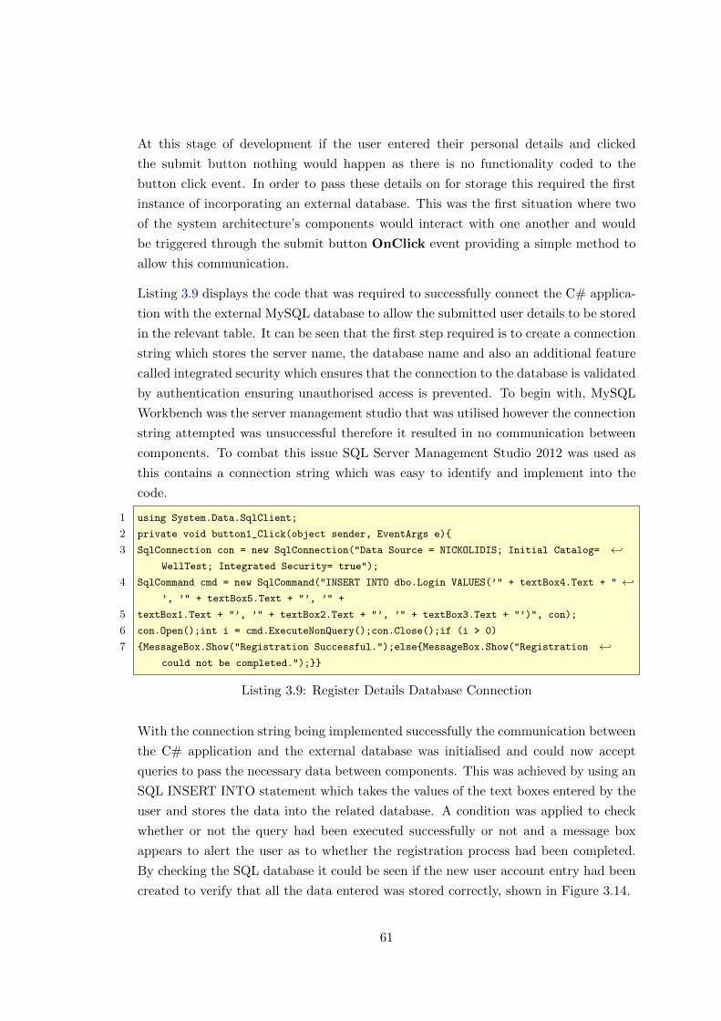
At this stage of development if the user entered their personal details and clicked
the submit button nothing would happen as there is no functionality coded to the
button click event. In order to pass these details on for storage this required the first
instance of incorporating an external database. This was the first situation where two
of the system architecture’s components would interact with one another and would
be triggered through the submit button OnClick event providing a simple method to
allow this communication.
Listing 3.9 displays the code that was required to successfully connect the C# applica-
tion with the external MySQL database to allow the submitted user details to be stored
in the relevant table. It can be seen that the first step required is to create a connection
string which stores the server name, the database name and also an additional feature
called integrated security which ensures that the connection to the database is validated
by authentication ensuring unauthorised access is prevented. To begin with, MySQL
Workbench was the server management studio that was utilised however the connection
string attempted was unsuccessful therefore it resulted in no communication between
components. To combat this issue SQL Server Management Studio 2012 was used as
this contains a connection string which was easy to identify and implement into the
code.
1 using System.Data.SqlClient;
2 private void button1_Click(object sender, EventArgs e){
3 SqlConnection con = new SqlConnection("Data Source = NICKOLIDIS; Initial Catalog= ←↩WellTest; Integrated Security= true");
4 SqlCommand cmd = new SqlCommand("INSERT INTO dbo.Login VALUES(’" + textBox4.Text + " ←↩’, ’" + textBox5.Text + "’, ’" +
5 textBox1.Text + "’, ’" + textBox2.Text + "’, ’" + textBox3.Text + "’)", con);
6 con.Open();int i = cmd.ExecuteNonQuery();con.Close();if (i > 0)
7 {MessageBox.Show("Registration Successful.");else{MessageBox.Show("Registration ←↩could not be completed.");}}
Listing 3.9: Register Details Database Connection
With the connection string being implemented successfully the communication between
the C# application and the external database was initialised and could now accept
queries to pass the necessary data between components. This was achieved by using an
SQL INSERT INTO statement which takes the values of the text boxes entered by the
user and stores the data into the related database. A condition was applied to check
whether or not the query had been executed successfully or not and a message box
appears to alert the user as to whether the registration process had been completed.
By checking the SQL database it could be seen if the new user account entry had been
created to verify that all the data entered was stored correctly, shown in Figure 3.14.
61
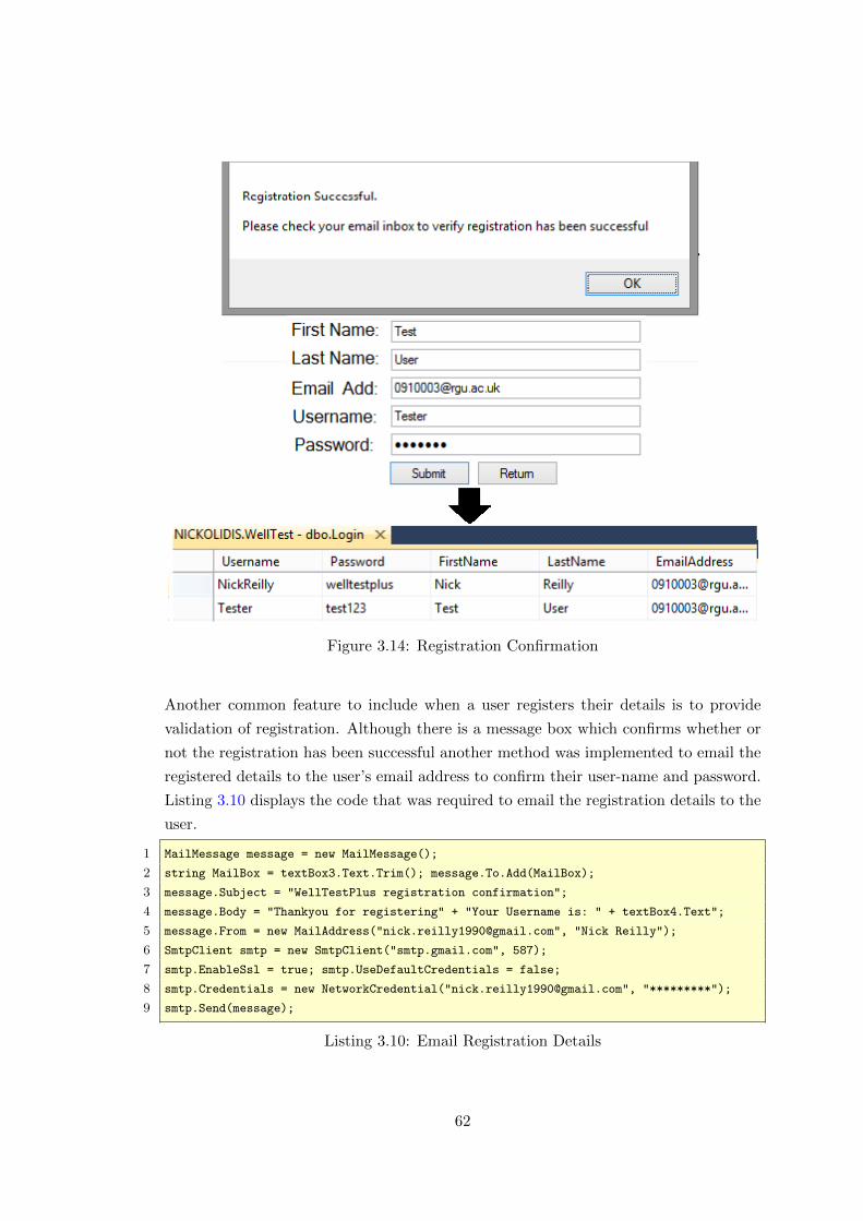
Figure 3.14: Registration Confirmation
Another common feature to include when a user registers their details is to provide
validation of registration. Although there is a message box which confirms whether or
not the registration has been successful another method was implemented to email the
registered details to the user’s email address to confirm their user-name and password.
Listing 3.10 displays the code that was required to email the registration details to the
user.
1 MailMessage message = new MailMessage();
2 string MailBox = textBox3.Text.Trim(); message.To.Add(MailBox);
3 message.Subject = "WellTestPlus registration confirmation";
4 message.Body = "Thankyou for registering" + "Your Username is: " + textBox4.Text";
5 message.From = new MailAddress("[email protected]", "Nick Reilly");
6 SmtpClient smtp = new SmtpClient("smtp.gmail.com", 587);
7 smtp.EnableSsl = true; smtp.UseDefaultCredentials = false;
8 smtp.Credentials = new NetworkCredential("[email protected]", "*********");
9 smtp.Send(message);
Listing 3.10: Email Registration Details
62

This method creates a new MailMessage() object which can accept the input of a
string containing the email address provided by the user. The string is then added to
the object which prepares it accept the subject and body of the message which is sent to
the user. In this body message the details entered into the text boxes are passed to the
email client which then requires the senders email details to actually send the message.
Upon providing all the necessary content for the email to be sent a Simple Mail Transfer
Protocol (SMTP) object was created to provide the functionality to send the message
from within the application across a network to the user [19]. This requires the port for
the mail client to be specified which initially caused problems in the implementation
of this method. The solution to this was that gmail accounts have a specific host and
port number to allow it to send emails. By inserting the code ”smtp.gmail.com”,
587 the .NET Mail client set-up was implemented successfully. At this point all that
was left to do was to add some security measures and then send the message using the
SMTP client.
With the validation of user details working as intended using the SMTP client method,
the registration form was now complete as seen in Figure 3.15 and the next required step
for the user to take would be to login to the application using the recently submitted
details. To do this the registration form needed to provide the capability to allow the
user to open the login form. Once the user has submitted their registration details,
if the task was unsuccessful when the message box is confirmed they are given the
opportunity to re-enter their desired details. If the registration was successful when
the message box is confirmed the user is then taken to the login form.
Figure 3.15: Complete Registration Form
63
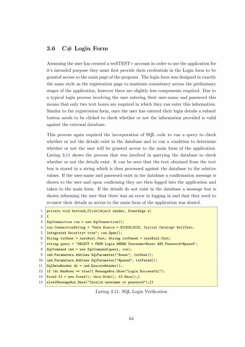
3.6 C# Login Form
Assuming the user has created a wellTEST+ account in order to use the application for
it’s intended purpose they must first provide their credentials in the Login form to be
granted access to the main page of the program. The login form was designed in exactly
the same style as the registration page to maintain consistency across the preliminary
stages of the application, however there are slightly less components required. Due to
a typical login process involving the user entering their user-name and password this
means that only two text boxes are required in which they can enter this information.
Similar to the registration form, once the user has entered their login details a submit
button needs to be clicked to check whether or not the information provided is valid
against the external database.
This process again required the incorporation of SQL code to run a query to check
whether or not the details exist in the database and to run a condition to determine
whether or not the user will be granted access to the main form of the application.
Listing 3.11 shows the process that was involved in querying the database to check
whether or not the details exist. It can be seen that the text obtained from the text
box is stored in a string which is then processed against the database to the relative
values. If the user-name and password exist in the database a confirmation message is
shown to the user and upon confirming they are then logged into the application and
taken to the main form. If the details do not exist in the database a message box is
shown informing the user that there was an error in logging in and that they need to
re-enter their details as access to the main form of the application was denied.
1 private void button4_Click(object sender, EventArgs e)
2 {
3 SqlConnection con = new SqlConnection();
4 con.ConnectionString = "Data Source = NICKOLIDIS; Initial Catalog= WellTest;
5 Integrated Security= true"; con.Open();
6 String txtUser = textBox1.Text; String txtPaswd = textBox2.Text;
7 string query = "SELECT * FROM Login WHERE Username=@user AND Password=@paswd";
8 SqlCommand cmd = new SqlCommand(query, con);
9 cmd.Parameters.Add(new SqlParameter("@user", txtUser));
10 cmd.Parameters.Add(new SqlParameter("@paswd", txtPaswd));
11 SqlDataReader dr = cmd.ExecuteReader();
12 if (dr.HasRows == true){ MessageBox.Show("Login Successful");
13 Form3 f3 = new Form3(); this.Hide(); f3.Show();}
14 else{MessageBox.Show("Invalid username or password");}}
Listing 3.11: SQL Login Verification
64

With the process employed to allow or deny the user access to the application depending
on the details they enter, the login process is complete however additional functionality
was incorporated to represent that of a commercial program. A common feature that
is typical when using an application that requires login credentials is to have a form
which allows the user to retrieve or reset their user-name or password, in case either of
these are forgotten at any point in time.
Figure 3.16: Completed Login Form
Figure 3.16 shows the final design of the login form that was implemented and shows
how the forgotten user-name and password options were incorporated into it. These
take the style of a text link which upon clicking opens up the relevant form to carry
out the appropriate task.
3.6.1 Username Retrieval Form
In the event of forgotten user-names and passwords, this would traditionally have re-
quired IT technicians to manually reset the login details. More recently computer
programs have incorporated methods to do this automatically using the application
itself.
A simple method was implemented to retrieve a particular user-name using the C#
application by requiring the user to enter their email address in a text box and upon
clicking the submit button a query would be run against the database to obtain the
65
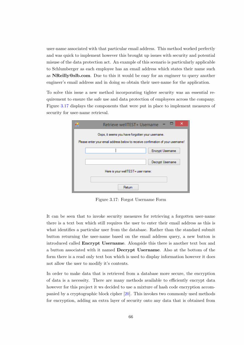
user-name associated with that particular email address. This method worked perfectly
and was quick to implement however this brought up issues with security and potential
misuse of the data protection act. An example of this scenario is particularly applicable
to Schlumberger as each employee has an email address which states their name such
as [email protected]. Due to this it would be easy for an engineer to query another
engineer’s email address and in doing so obtain their user-name for the application.
To solve this issue a new method incorporating tighter security was an essential re-
quirement to ensure the safe use and data protection of employees across the company.
Figure 3.17 displays the components that were put in place to implement measures of
security for user-name retrieval.
Figure 3.17: Forgot Username Form
It can be seen that to invoke security measures for retrieving a forgotten user-name
there is a text box which still requires the user to enter their email address as this is
what identifies a particular user from the database. Rather than the standard submit
button returning the user-name based on the email address query, a new button is
introduced called Encrypt Username. Alongside this there is another text box and
a button associated with it named Decrypt Username. Also at the bottom of the
form there is a read only text box which is used to display information however it does
not allow the user to modify it’s contents.
In order to make data that is retrieved from a database more secure, the encryption
of data is a necessity. There are many methods available to efficiently encrypt data
however for this project it ws decided to use a mixture of hash code encryption accom-
panied by a cryptographic block cipher [20]. This invokes two commonly used methods
for encryption, adding an extra layer of security onto any data that is obtained from
66
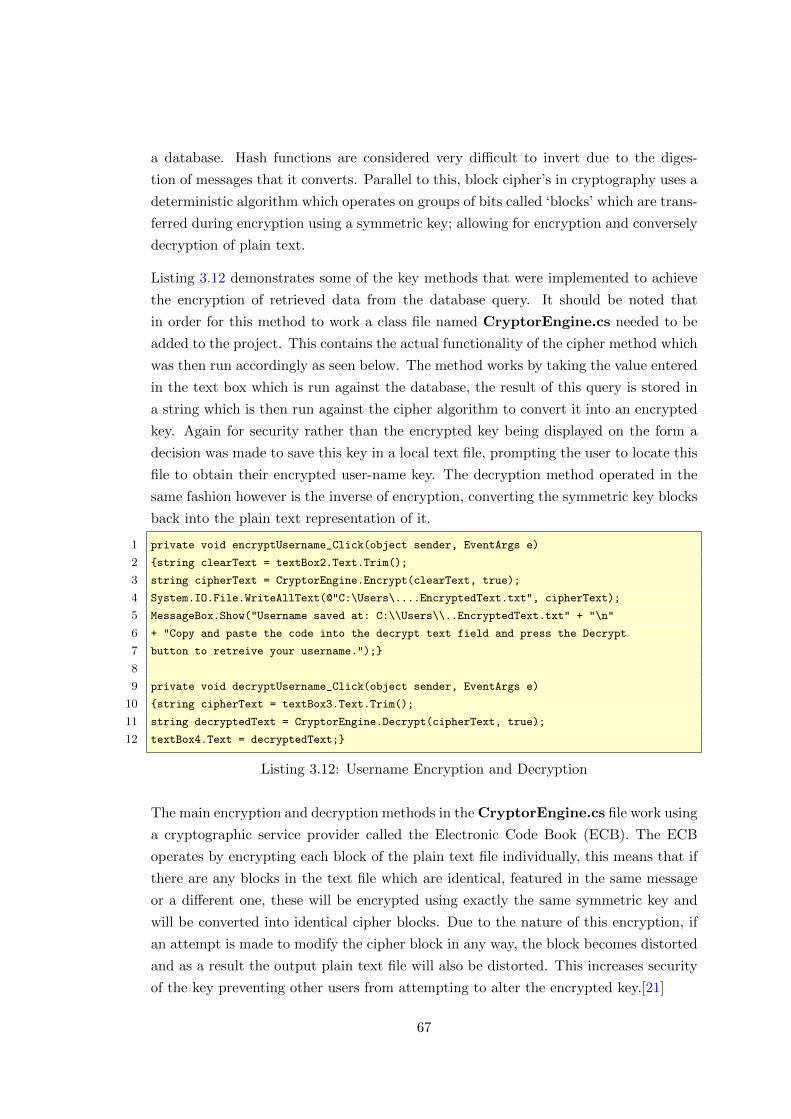
a database. Hash functions are considered very difficult to invert due to the diges-
tion of messages that it converts. Parallel to this, block cipher’s in cryptography uses a
deterministic algorithm which operates on groups of bits called ‘blocks’ which are trans-
ferred during encryption using a symmetric key; allowing for encryption and conversely
decryption of plain text.
Listing 3.12 demonstrates some of the key methods that were implemented to achieve
the encryption of retrieved data from the database query. It should be noted that
in order for this method to work a class file named CryptorEngine.cs needed to be
added to the project. This contains the actual functionality of the cipher method which
was then run accordingly as seen below. The method works by taking the value entered
in the text box which is run against the database, the result of this query is stored in
a string which is then run against the cipher algorithm to convert it into an encrypted
key. Again for security rather than the encrypted key being displayed on the form a
decision was made to save this key in a local text file, prompting the user to locate this
file to obtain their encrypted user-name key. The decryption method operated in the
same fashion however is the inverse of encryption, converting the symmetric key blocks
back into the plain text representation of it.
1 private void encryptUsername_Click(object sender, EventArgs e)
2 {string clearText = textBox2.Text.Trim();
3 string cipherText = CryptorEngine.Encrypt(clearText, true);
4 System.IO.File.WriteAllText(@"C:\Users\....EncryptedText.txt", cipherText);
5 MessageBox.Show("Username saved at: C:\\Users\\..EncryptedText.txt" + "\n"
6 + "Copy and paste the code into the decrypt text field and press the Decrypt
7 button to retreive your username.");}
8
9 private void decryptUsername_Click(object sender, EventArgs e)
10 {string cipherText = textBox3.Text.Trim();
11 string decryptedText = CryptorEngine.Decrypt(cipherText, true);
12 textBox4.Text = decryptedText;}
Listing 3.12: Username Encryption and Decryption
The main encryption and decryption methods in the CryptorEngine.cs file work using
a cryptographic service provider called the Electronic Code Book (ECB). The ECB
operates by encrypting each block of the plain text file individually, this means that if
there are any blocks in the text file which are identical, featured in the same message
or a different one, these will be encrypted using exactly the same symmetric key and
will be converted into identical cipher blocks. Due to the nature of this encryption, if
an attempt is made to modify the cipher block in any way, the block becomes distorted
and as a result the output plain text file will also be distorted. This increases security
of the key preventing other users from attempting to alter the encrypted key.[21]
67
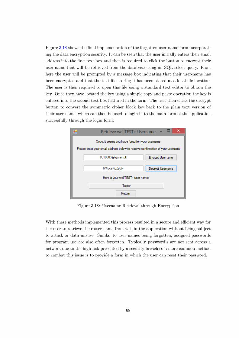
Figure 3.18 shows the final implementation of the forgotten user-name form incorporat-
ing the data encryption security. It can be seen that the user initially enters their email
address into the first text box and then is required to click the button to encrypt their
user-name that will be retrieved from the database using an SQL select query. From
here the user will be prompted by a message box indicating that their user-name has
been encrypted and that the text file storing it has been stored at a local file location.
The user is then required to open this file using a standard text editor to obtain the
key. Once they have located the key using a simple copy and paste operation the key is
entered into the second text box featured in the form. The user then clicks the decrypt
button to convert the symmetric cipher block key back to the plain text version of
their user-name, which can then be used to login in to the main form of the application
successfully through the login form.
Figure 3.18: Username Retrieval through Encryption
With these methods implemented this process resulted in a secure and efficient way for
the user to retrieve their user-name from within the application without being subject
to attack or data misuse. Similar to user names being forgotten, assigned passwords
for program use are also often forgotten. Typically password’s are not sent across a
network due to the high risk presented by a security breach so a more common method
to combat this issue is to provide a form in which the user can reset their password.
68
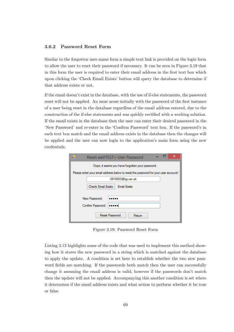
3.6.2 Password Reset Form
Similar to the forgotten user-name form a simple text link is provided on the login form
to allow the user to reset their password if necessary. It can be seen in Figure 3.19 that
in this form the user is required to enter their email address in the first text box which
upon clicking the ‘Check Email Exists’ button will query the database to determine if
that address exists or not.
If the email doesn’t exist in the database, with the use of if-else statements, the password
reset will not be applied. An issue arose initially with the password of the first instance
of a user being reset in the database regardless of the email address entered, due to the
construction of the if-else statements and was quickly rectified with a working solution.
If the email exists in the database then the user can enter their desired password in the
‘New Password’ and re-enter in the ‘Confirm Password’ text box. If the password’s in
each text box match and the email address exists in the database then the changes will
be applied and the user can now login to the application’s main form using the new
credentials.
Figure 3.19: Password Reset Form
Listing 3.13 highlights some of the code that was used to implement this method show-
ing how it stores the new password in a string which is matched against the database
to apply the update. A condition is set here to establish whether the two new pass-
word fields are matching. If the passwords both match then the user can successfully
change it assuming the email address is valid, however if the passwords don’t match
then the update will not be applied. Accompanying this another condition is set where
it determines if the email address exists and what action to perform whether it be true
or false.
69
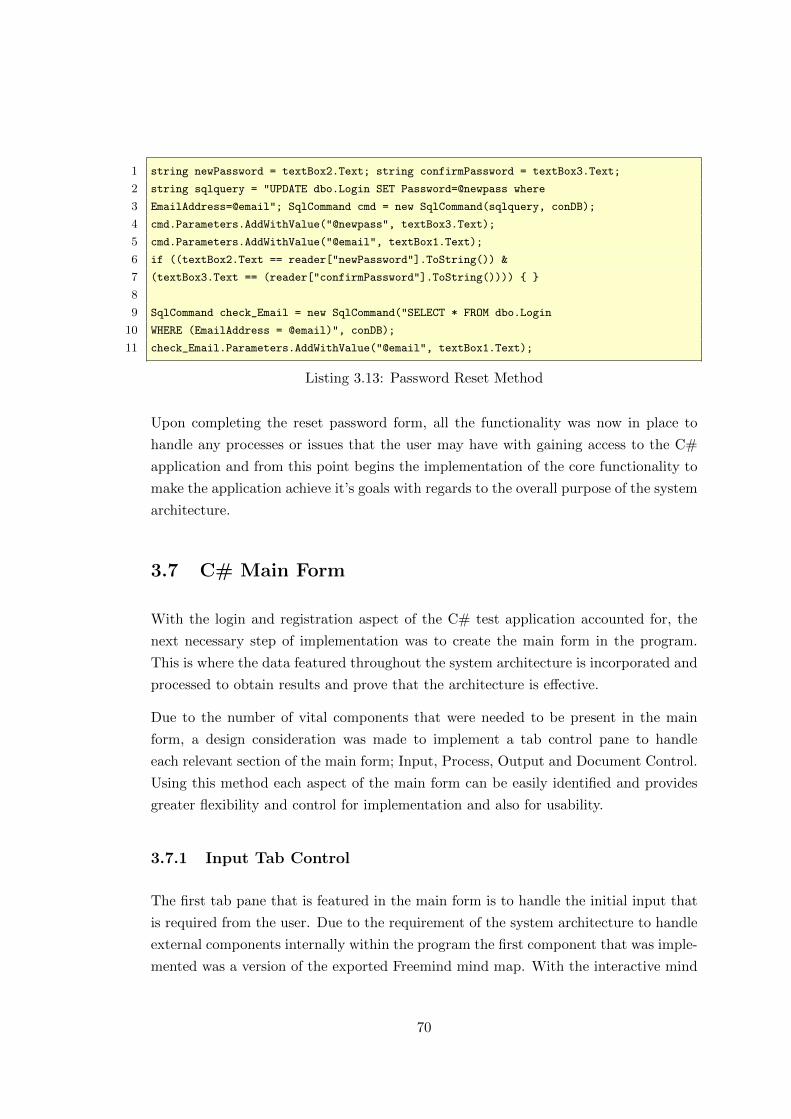
1 string newPassword = textBox2.Text; string confirmPassword = textBox3.Text;
2 string sqlquery = "UPDATE dbo.Login SET Password=@newpass where
3 EmailAddress=@email"; SqlCommand cmd = new SqlCommand(sqlquery, conDB);
4 cmd.Parameters.AddWithValue("@newpass", textBox3.Text);
5 cmd.Parameters.AddWithValue("@email", textBox1.Text);
6 if ((textBox2.Text == reader["newPassword"].ToString()) &
7 (textBox3.Text == (reader["confirmPassword"].ToString()))) { }
8
9 SqlCommand check_Email = new SqlCommand("SELECT * FROM dbo.Login
10 WHERE (EmailAddress = @email)", conDB);
11 check_Email.Parameters.AddWithValue("@email", textBox1.Text);
Listing 3.13: Password Reset Method
Upon completing the reset password form, all the functionality was now in place to
handle any processes or issues that the user may have with gaining access to the C#
application and from this point begins the implementation of the core functionality to
make the application achieve it’s goals with regards to the overall purpose of the system
architecture.
3.7 C# Main Form
With the login and registration aspect of the C# test application accounted for, the
next necessary step of implementation was to create the main form in the program.
This is where the data featured throughout the system architecture is incorporated and
processed to obtain results and prove that the architecture is effective.
Due to the number of vital components that were needed to be present in the main
form, a design consideration was made to implement a tab control pane to handle
each relevant section of the main form; Input, Process, Output and Document Control.
Using this method each aspect of the main form can be easily identified and provides
greater flexibility and control for implementation and also for usability.
3.7.1 Input Tab Control
The first tab pane that is featured in the main form is to handle the initial input that
is required from the user. Due to the requirement of the system architecture to handle
external components internally within the program the first component that was imple-
mented was a version of the exported Freemind mind map. With the interactive mind
70

map being exported as a Flash Applet, Microsoft Visual Studio provides a component
which allows for this type of file to be included in the application.
By implementing a Web Browser component into the main form this allowed for files
that are typically run using a web browser from a local file location to be displayed
internally from the application as seen in Figure3.20. This replicates the file being
run using an Internet browser so efficiently allows for the export Flash Applet mind
map to be displayed in the form. Alongside this due to the nature of the web browser
component the Flash Applet mind map retains it’s interactivity allowing the user to
traverse through the map as would be carried out in the external Freemind software
package.
Figure 3.20: Internal Display of Mind Map
The purpose of incorporating the Flash Applet export of the mind map was for it to be
used as a reference point for the user. In traversing through the map’s nodes the user
will identify the parameters of well testing that is applicable to that particular test and
then the relevant information will be processed in the next tab pane featured in the
tab control. As the tab panes can be selected as required, this map will be frequently
referenced to ensure that the correct data has been accounted for in the next tab pane.
Alongside this another aspect of the main program is one of the final steps, document
creation. Here the user incorporates data featured throughout the program to create
an official well test document. One of the requirements for this was to capture an image
of the mind map so it could be displayed in the document to identify which parameters
were selected for the test. Because of this a method was needed to capture an image
of the mind map however there were difficulties in doing so before reaching an effective
solution.
71
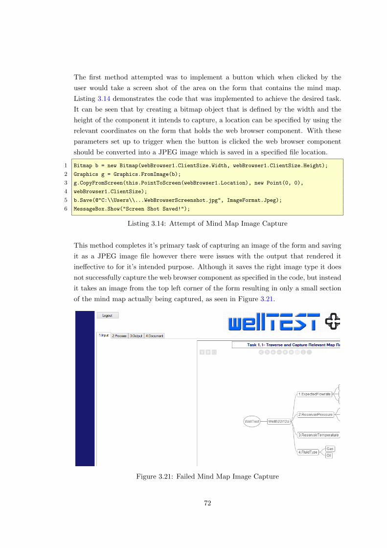
The first method attempted was to implement a button which when clicked by the
user would take a screen shot of the area on the form that contains the mind map.
Listing 3.14 demonstrates the code that was implemented to achieve the desired task.
It can be seen that by creating a bitmap object that is defined by the width and the
height of the component it intends to capture, a location can be specified by using the
relevant coordinates on the form that holds the web browser component. With these
parameters set up to trigger when the button is clicked the web browser component
should be converted into a JPEG image which is saved in a specified file location.
1 Bitmap b = new Bitmap(webBrowser1.ClientSize.Width, webBrowser1.ClientSize.Height);
2 Graphics g = Graphics.FromImage(b);
3 g.CopyFromScreen(this.PointToScreen(webBrowser1.Location), new Point(0, 0),
4 webBrowser1.ClientSize);
5 b.Save(@"C:\\Users\\...WebBrowserScreenshot.jpg", ImageFormat.Jpeg);
6 MessageBox.Show("Screen Shot Saved!");
Listing 3.14: Attempt of Mind Map Image Capture
This method completes it’s primary task of capturing an image of the form and saving
it as a JPEG image file however there were issues with the output that rendered it
ineffective to for it’s intended purpose. Although it saves the right image type it does
not successfully capture the web browser component as specified in the code, but instead
it takes an image from the top left corner of the form resulting in only a small section
of the mind map actually being captured, as seen in Figure 3.21.
Figure 3.21: Failed Mind Map Image Capture
72
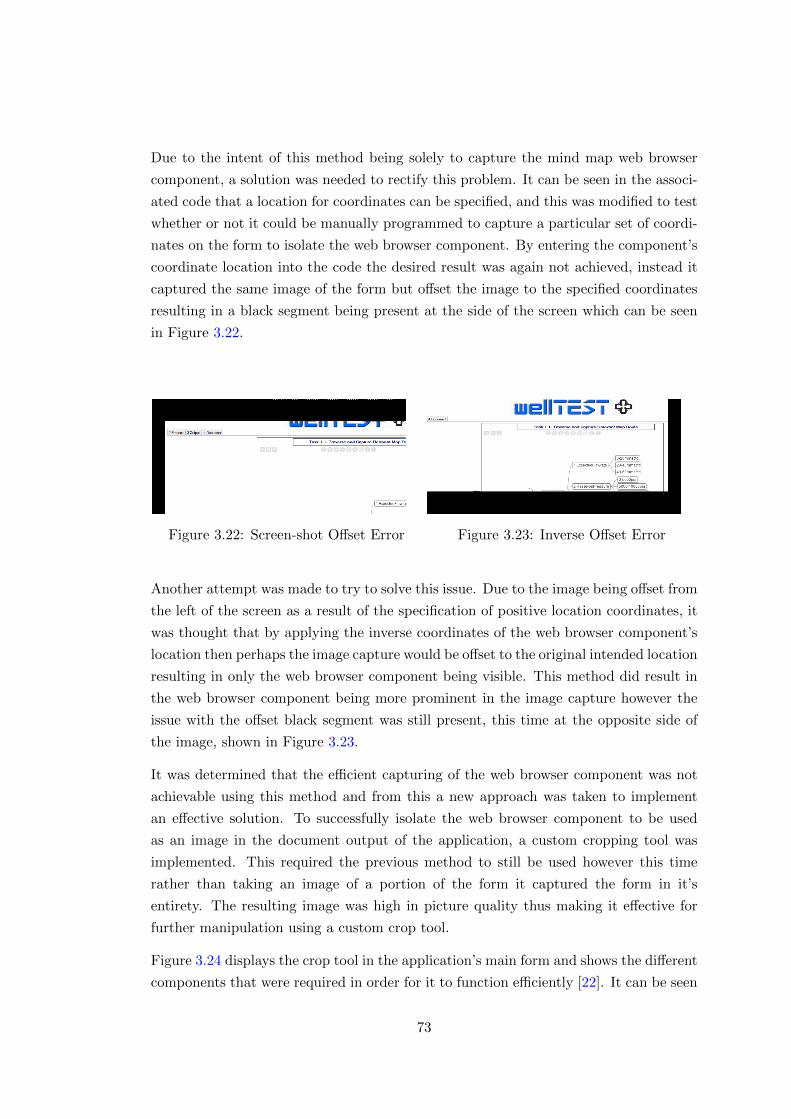
Due to the intent of this method being solely to capture the mind map web browser
component, a solution was needed to rectify this problem. It can be seen in the associ-
ated code that a location for coordinates can be specified, and this was modified to test
whether or not it could be manually programmed to capture a particular set of coordi-
nates on the form to isolate the web browser component. By entering the component’s
coordinate location into the code the desired result was again not achieved, instead it
captured the same image of the form but offset the image to the specified coordinates
resulting in a black segment being present at the side of the screen which can be seen
in Figure 3.22.
Figure 3.22: Screen-shot Offset Error Figure 3.23: Inverse Offset Error
Another attempt was made to try to solve this issue. Due to the image being offset from
the left of the screen as a result of the specification of positive location coordinates, it
was thought that by applying the inverse coordinates of the web browser component’s
location then perhaps the image capture would be offset to the original intended location
resulting in only the web browser component being visible. This method did result in
the web browser component being more prominent in the image capture however the
issue with the offset black segment was still present, this time at the opposite side of
the image, shown in Figure 3.23.
It was determined that the efficient capturing of the web browser component was not
achievable using this method and from this a new approach was taken to implement
an effective solution. To successfully isolate the web browser component to be used
as an image in the document output of the application, a custom cropping tool was
implemented. This required the previous method to still be used however this time
rather than taking an image of a portion of the form it captured the form in it’s
entirety. The resulting image was high in picture quality thus making it effective for
further manipulation using a custom crop tool.
Figure 3.24 displays the crop tool in the application’s main form and shows the different
components that were required in order for it to function efficiently [22]. It can be seen
73
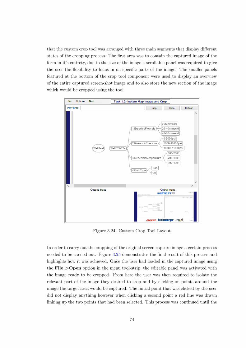
that the custom crop tool was arranged with three main segments that display different
states of the cropping process. The first area was to contain the captured image of the
form in it’s entirety, due to the size of the image a scrollable panel was required to give
the user the flexibility to focus in on specific parts of the image. The smaller panels
featured at the bottom of the crop tool component were used to display an overview
of the entire captured screen-shot image and to also store the new section of the image
which would be cropped using the tool.
Figure 3.24: Custom Crop Tool Layout
In order to carry out the cropping of the original screen capture image a certain process
needed to be carried out. Figure 3.25 demonstrates the final result of this process and
highlights how it was achieved. Once the user had loaded in the captured image using
the File >Open option in the menu tool-strip, the editable panel was activated with
the image ready to be cropped. From here the user was then required to isolate the
relevant part of the image they desired to crop and by clicking on points around the
image the target area would be captured. The initial point that was clicked by the user
did not display anything however when clicking a second point a red line was drawn
linking up the two points that had been selected. This process was continued until the
74
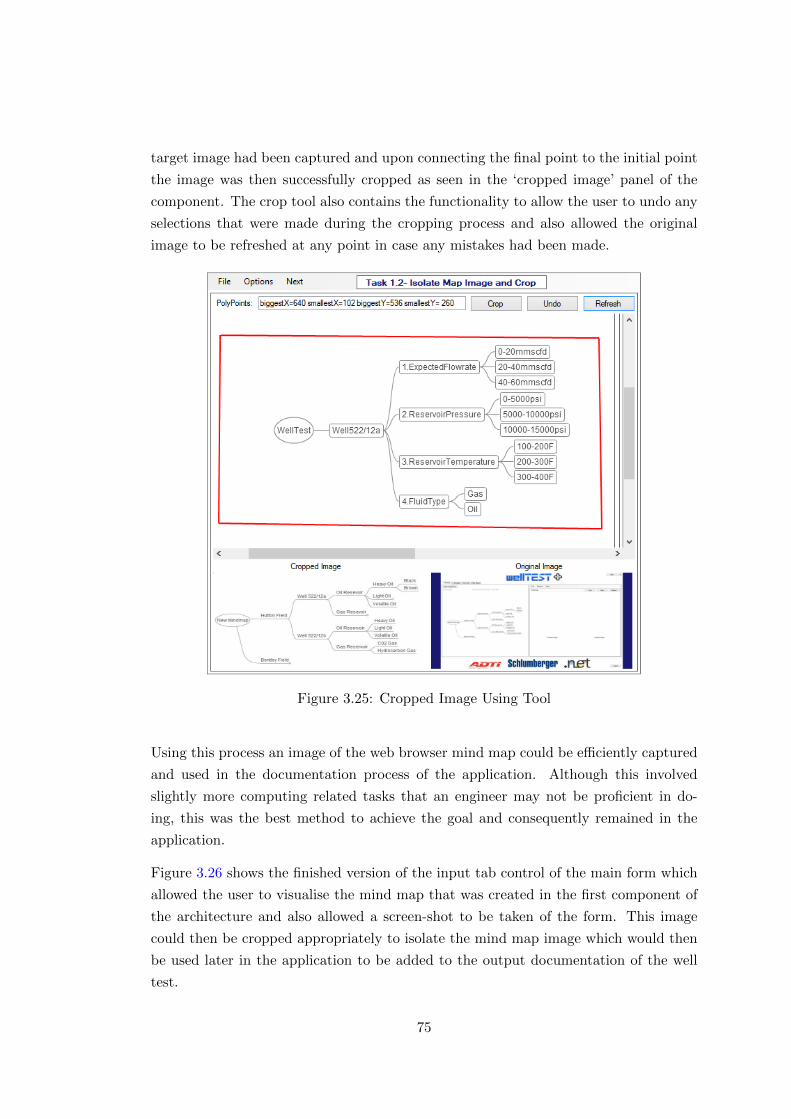
target image had been captured and upon connecting the final point to the initial point
the image was then successfully cropped as seen in the ‘cropped image’ panel of the
component. The crop tool also contains the functionality to allow the user to undo any
selections that were made during the cropping process and also allowed the original
image to be refreshed at any point in case any mistakes had been made.
Figure 3.25: Cropped Image Using Tool
Using this process an image of the web browser mind map could be efficiently captured
and used in the documentation process of the application. Although this involved
slightly more computing related tasks that an engineer may not be proficient in do-
ing, this was the best method to achieve the goal and consequently remained in the
application.
Figure 3.26 shows the finished version of the input tab control of the main form which
allowed the user to visualise the mind map that was created in the first component of
the architecture and also allowed a screen-shot to be taken of the form. This image
could then be cropped appropriately to isolate the mind map image which would then
be used later in the application to be added to the output documentation of the well
test.
75
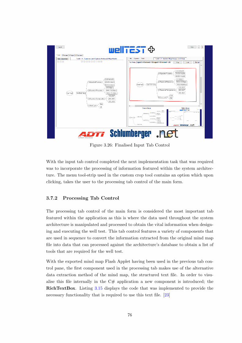
Figure 3.26: Finalised Input Tab Control
With the input tab control completed the next implementation task that was required
was to incorporate the processing of information featured within the system architec-
ture. The menu tool-strip used in the custom crop tool contains an option which upon
clicking, takes the user to the processing tab control of the main form.
3.7.2 Processing Tab Control
The processing tab control of the main form is considered the most important tab
featured within the application as this is where the data used throughout the system
architecture is manipulated and processed to obtain the vital information when design-
ing and executing the well test. This tab control features a variety of components that
are used in sequence to convert the information extracted from the original mind map
file into data that can processed against the architecture’s database to obtain a list of
tools that are required for the well test.
With the exported mind map Flash Applet having been used in the previous tab con-
trol pane, the first component used in the processing tab makes use of the alternative
data extraction method of the mind map, the structured text file. In order to visu-
alise this file internally in the C# application a new component is introduced; the
RichTextBox. Listing 3.15 displays the code that was implemented to provide the
necessary functionality that is required to use this text file. [23]
76
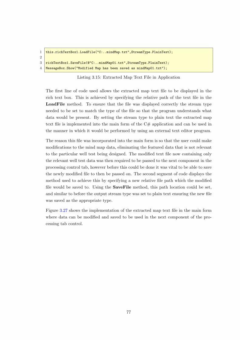
1 this.richTextBox1.LoadFile("C:..mindMap.txt",StreamType.PlainText);
2
3 richTextBox1.SaveFile(@"C:..mindMap01.txt",StreamType.PlainText);
4 MessageBox.Show("Modified Map has been saved as mindMap01.txt");
Listing 3.15: Extracted Map Text File in Application
The first line of code used allows the extracted map text file to be displayed in the
rich text box. This is achieved by specifying the relative path of the text file in the
LoadFile method. To ensure that the file was displayed correctly the stream type
needed to be set to match the type of the file so that the program understands what
data would be present. By setting the stream type to plain text the extracted map
text file is implemented into the main form of the C# application and can be used in
the manner in which it would be performed by using an external text editor program.
The reason this file was incorporated into the main form is so that the user could make
modifications to the mind map data, eliminating the featured data that is not relevant
to the particular well test being designed. The modified text file now containing only
the relevant well test data was then required to be passed to the next component in the
processing control tab, however before this could be done it was vital to be able to save
the newly modified file to then be passed on. The second segment of code displays the
method used to achieve this by specifying a new relative file path which the modified
file would be saved to. Using the SaveFile method, this path location could be set,
and similar to before the output stream type was set to plain text ensuring the new file
was saved as the appropriate type.
Figure 3.27 shows the implementation of the extracted map text file in the main form
where data can be modified and saved to be used in the next component of the pro-
cessing tab control.
77
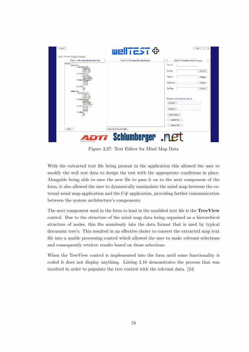
Figure 3.27: Text Editor for Mind Map Data
With the extracted text file being present in the application this allowed the user to
modify the well test data to design the test with the appropriate conditions in place.
Alongside being able to save the new file to pass it on to the next component of the
form, it also allowed the user to dynamically manipulate the mind map between the ex-
ternal mind map application and the C# application, providing further communication
between the system architecture’s components.
The next component used in the form to load in the modified text file is the TreeView
control. Due to the structure of the mind map data being organised as a hierarchical
structure of nodes, this fits seamlessly into the data format that is used by typical
document tree’s. This resulted in an effective choice to convert the extracted map text
file into a usable processing control which allowed the user to make relevant selections
and consequently retrieve results based on those selections.
When the TreeView control is implemented into the form until some functionality is
coded it does not display anything. Listing 3.16 demonstrates the process that was
involved in order to populate the tree control with the relevant data. [24]
78
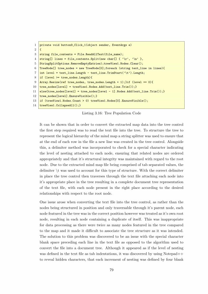
1 private void button9_Click_1(object sender, EventArgs e)
2 {
3 string file_contents = File.ReadAllText(file_name);
4 string[] lines = file_contents.Split(new char[] { ’\r’, ’\n’ },
5 StringSplitOptions.RemoveEmptyEntries);treeView1.Nodes.Clear();
6 TreeNode[] tree_nodes = new TreeNode[0];foreach (string text_line in lines){
7 int level = text_line.Length - text_line.TrimStart(’\t’).Length;
8 if (level >= tree_nodes.Length){
9 Array.Resize(ref tree_nodes, tree_nodes.Length + 1);}if (level == 0){
10 tree_nodes[level] = treeView1.Nodes.Add(text_line.Trim());}
11 else{tree_nodes[level] = tree_nodes[level - 1].Nodes.Add(text_line.Trim());}
12 tree_nodes[level].EnsureVisible();}
13 if (treeView1.Nodes.Count > 0) treeView1.Nodes[0].EnsureVisible();
14 treeView1.CollapseAll();}
Listing 3.16: Tree Population Code
It can be shown that in order to convert the extracted map data into the tree control
the first step required was to read the text file into the tree. To structure the tree to
represent the logical hierarchy of the mind map a string splitter was used to ensure that
at the end of each row in the file a new line was created in the tree control. Alongside
this, a delimiter method was incorporated to check for a special character indicating
the level of nesting attached to each node, ensuring that related nodes are ordered
appropriately and that it’s structural integrity was maintained with regard to the root
node. Due to the extracted mind map file being comprised of tab separated values, the
delimiter \t was used to account for this type of structure. With the correct delimiter
in place the tree control then traverses through the text file attaching each node into
it’s appropriate place in the tree resulting in a complete document tree representation
of the text file, with each node present in the right place according to the desired
relationships with respect to the root node.
One issue arose when converting the text file into the tree control, as rather than the
nodes being structured in position and only traversable through it’s parent node, each
node featured in the tree was in the correct position however was treated as it’s own root
node, resulting in each node containing a duplicate of itself. This was inappropriate
for data processing as there were twice as many nodes featured in the tree compared
to the map and it made it difficult to associate the tree structure as it was intended.
The solution to this problem was discovered to be an issue with the special character
blank space preceding each line in the text file as opposed to the algorithm used to
convert the file into a document tree. Although it appeared as if the level of nesting
was defined in the text file as tab indentations, it was discovered by using Notepad++
to reveal hidden characters, that each increment of nesting was defined by four blank
79
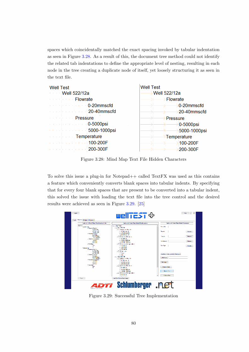
spaces which coincidentally matched the exact spacing invoked by tabular indentation
as seen in Figure 3.28. As a result of this, the document tree method could not identify
the related tab indentations to define the appropriate level of nesting, resulting in each
node in the tree creating a duplicate node of itself, yet loosely structuring it as seen in
the text file.
Figure 3.28: Mind Map Text File Hidden Characters
To solve this issue a plug-in for Notepad++ called TextFX was used as this contains
a feature which conveniently converts blank spaces into tabular indents. By specifying
that for every four blank spaces that are present to be converted into a tabular indent,
this solved the issue with loading the text file into the tree control and the desired
results were achieved as seen in Figure 3.29. [25]
Figure 3.29: Successful Tree Implementation
80

With the implementation of the tree control completed with the extracted mind map
text file the user could successfully traverse through the tree inspecting the various
nodes that were present relating to well test design parameters. Listing 3.17 shows
that additional tree control methods were implemented to permit the user to make
further modifications to the content of the tree. This incorporated methods to allow
the user to add new nodes to the tree by entering the name of the node and specifying
on the tree where it should be placed, to remove a select node and also to edit the
text of a selected node. Alongside this, the possibility to expand or collapse the entire
tree was implemented to allow the user to view the tree in it’s entirety or alternatively
reduce the tree to it’s initial state of only displaying the root node.
1 //Add Node
2 TreeNode newNode = new TreeNode(textBox1.Text);
3 treeView1.SelectedNode.Nodes.Add(newNode);
4 //Edit Node
5 treeView1.SelectedNode.Text = textBox2.Text;
6 //Remove Node
7 treeView1.Nodes.Remove(treeView1.SelectedNode);
8 //Expand Tree
9 treeView1.ExpandAll();
10 //Collapse Tree
11 treeView1.CollapseAll();
Listing 3.17: Custom Tree Control
At this stage the tree control component had been incorporated into the application
with all the required functionality working and the correct data being presented main-
taining it’s hierarchical structure. The final feature that was needed from the tree
control was the processing of the featured data. One of the drawbacks of using the
tree control is that it only allows for one node to be selected through a mouse click,
this meant that only one tree node could be processed at any given time whereas it
was required to process multiple tree nodes to fully capture the entire well test design
process. An attempt was made to solve this problem by introducing check boxes to
each tree node allowing the user to specify which nodes have been selected for process-
ing. Unfortunately despite multiple nodes being checked for selection it could not be
determined how to pass this information forward to obtain the results needed from the
tree selection, instead only the top most selected node would be processed against the
database to retrieve the associated tool. Due to multiple items needing to be selected
to establish all the tools required for the well test, another method was attempted to
reach an effective solution.
A new approach was taken to allow the processing of multiple tree items to be achieved.
This detracts from the previously attempted methods where the nodes were processed
81
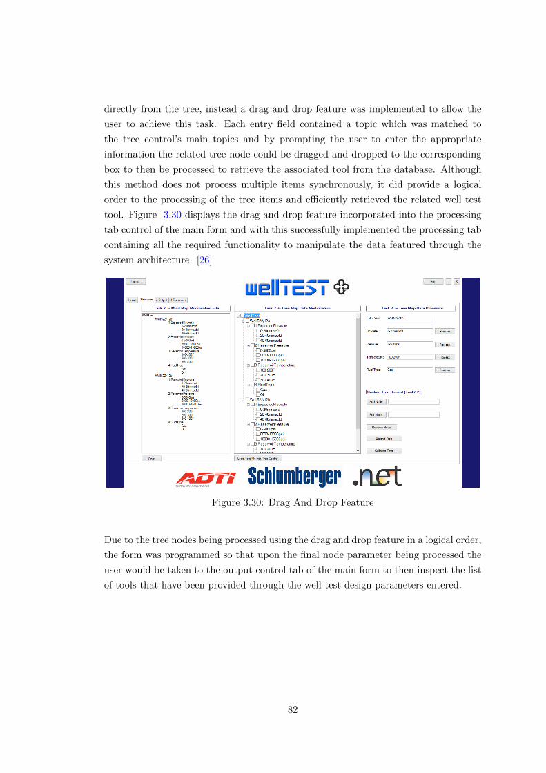
directly from the tree, instead a drag and drop feature was implemented to allow the
user to achieve this task. Each entry field contained a topic which was matched to
the tree control’s main topics and by prompting the user to enter the appropriate
information the related tree node could be dragged and dropped to the corresponding
box to then be processed to retrieve the associated tool from the database. Although
this method does not process multiple items synchronously, it did provide a logical
order to the processing of the tree items and efficiently retrieved the related well test
tool. Figure 3.30 displays the drag and drop feature incorporated into the processing
tab control of the main form and with this successfully implemented the processing tab
containing all the required functionality to manipulate the data featured through the
system architecture. [26]
Figure 3.30: Drag And Drop Feature
Due to the tree nodes being processed using the drag and drop feature in a logical order,
the form was programmed so that upon the final node parameter being processed the
user would be taken to the output control tab of the main form to then inspect the list
of tools that have been provided through the well test design parameters entered.
82
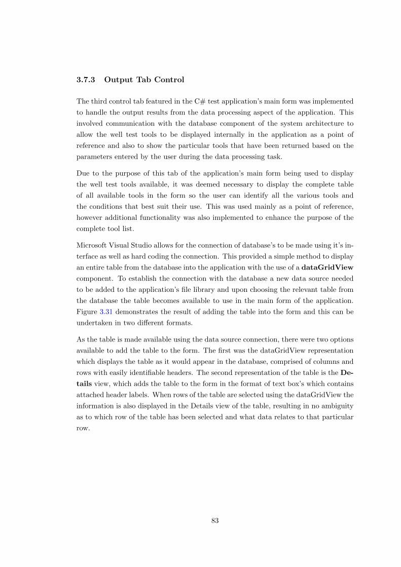
3.7.3 Output Tab Control
The third control tab featured in the C# test application’s main form was implemented
to handle the output results from the data processing aspect of the application. This
involved communication with the database component of the system architecture to
allow the well test tools to be displayed internally in the application as a point of
reference and also to show the particular tools that have been returned based on the
parameters entered by the user during the data processing task.
Due to the purpose of this tab of the application’s main form being used to display
the well test tools available, it was deemed necessary to display the complete table
of all available tools in the form so the user can identify all the various tools and
the conditions that best suit their use. This was used mainly as a point of reference,
however additional functionality was also implemented to enhance the purpose of the
complete tool list.
Microsoft Visual Studio allows for the connection of database’s to be made using it’s in-
terface as well as hard coding the connection. This provided a simple method to display
an entire table from the database into the application with the use of a dataGridView
component. To establish the connection with the database a new data source needed
to be added to the application’s file library and upon choosing the relevant table from
the database the table becomes available to use in the main form of the application.
Figure 3.31 demonstrates the result of adding the table into the form and this can be
undertaken in two different formats.
As the table is made available using the data source connection, there were two options
available to add the table to the form. The first was the dataGridView representation
which displays the table as it would appear in the database, comprised of columns and
rows with easily identifiable headers. The second representation of the table is the De-
tails view, which adds the table to the form in the format of text box’s which contains
attached header labels. When rows of the table are selected using the dataGridView the
information is also displayed in the Details view of the table, resulting in no ambiguity
as to which row of the table has been selected and what data relates to that particular
row.
83
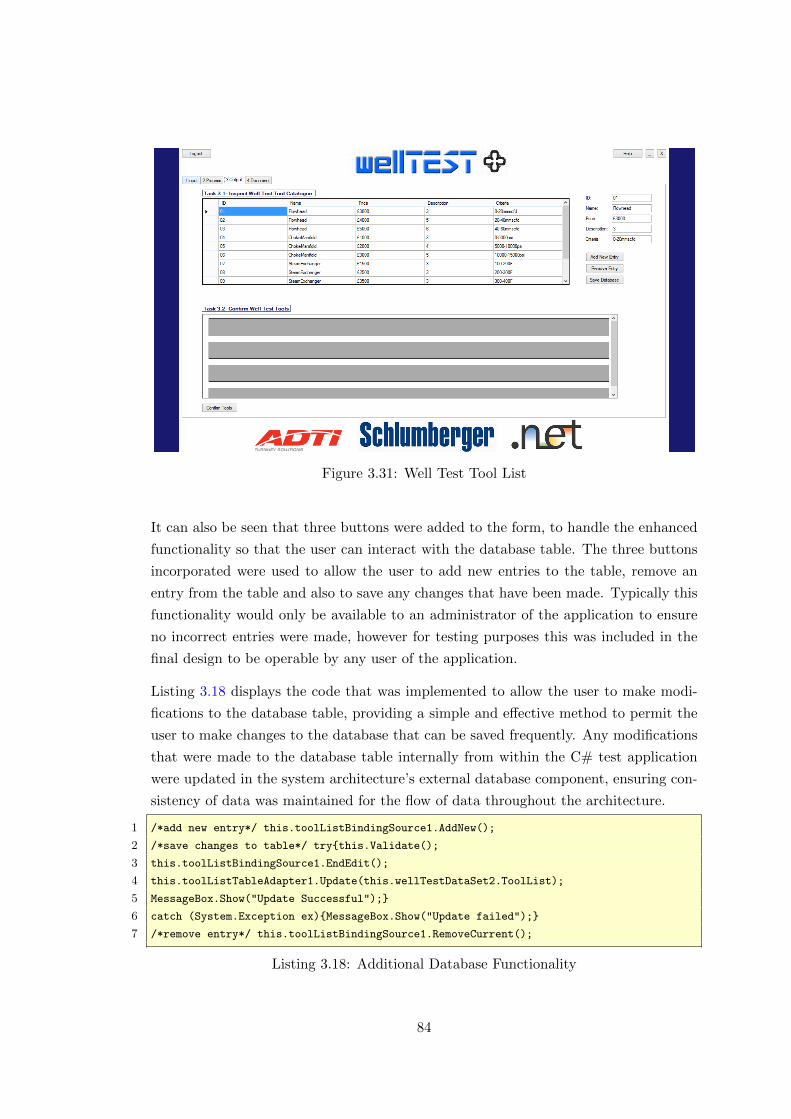
Figure 3.31: Well Test Tool List
It can also be seen that three buttons were added to the form, to handle the enhanced
functionality so that the user can interact with the database table. The three buttons
incorporated were used to allow the user to add new entries to the table, remove an
entry from the table and also to save any changes that have been made. Typically this
functionality would only be available to an administrator of the application to ensure
no incorrect entries were made, however for testing purposes this was included in the
final design to be operable by any user of the application.
Listing 3.18 displays the code that was implemented to allow the user to make modi-
fications to the database table, providing a simple and effective method to permit the
user to make changes to the database that can be saved frequently. Any modifications
that were made to the database table internally from within the C# test application
were updated in the system architecture’s external database component, ensuring con-
sistency of data was maintained for the flow of data throughout the architecture.
1 /*add new entry*/ this.toolListBindingSource1.AddNew();
2 /*save changes to table*/ try{this.Validate();
3 this.toolListBindingSource1.EndEdit();
4 this.toolListTableAdapter1.Update(this.wellTestDataSet2.ToolList);
5 MessageBox.Show("Update Successful");}
6 catch (System.Exception ex){MessageBox.Show("Update failed");}
7 /*remove entry*/ this.toolListBindingSource1.RemoveCurrent();
Listing 3.18: Additional Database Functionality
84
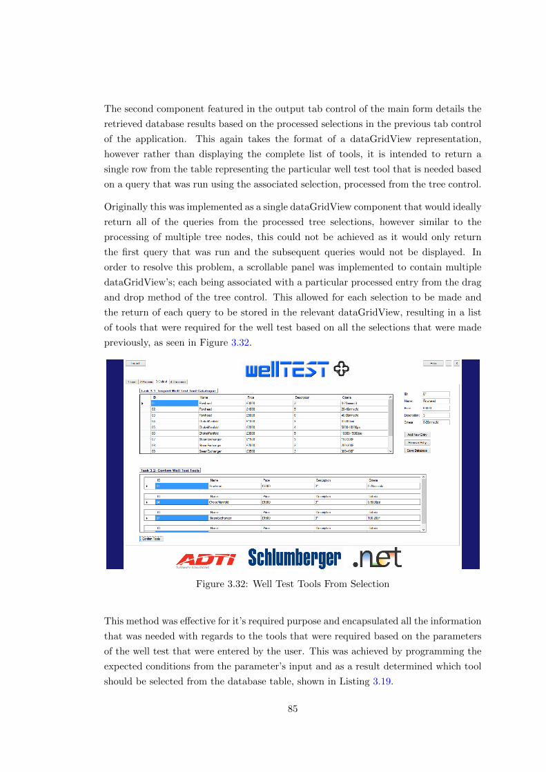
The second component featured in the output tab control of the main form details the
retrieved database results based on the processed selections in the previous tab control
of the application. This again takes the format of a dataGridView representation,
however rather than displaying the complete list of tools, it is intended to return a
single row from the table representing the particular well test tool that is needed based
on a query that was run using the associated selection, processed from the tree control.
Originally this was implemented as a single dataGridView component that would ideally
return all of the queries from the processed tree selections, however similar to the
processing of multiple tree nodes, this could not be achieved as it would only return
the first query that was run and the subsequent queries would not be displayed. In
order to resolve this problem, a scrollable panel was implemented to contain multiple
dataGridView’s; each being associated with a particular processed entry from the drag
and drop method of the tree control. This allowed for each selection to be made and
the return of each query to be stored in the relevant dataGridView, resulting in a list
of tools that were required for the well test based on all the selections that were made
previously, as seen in Figure 3.32.
Figure 3.32: Well Test Tools From Selection
This method was effective for it’s required purpose and encapsulated all the information
that was needed with regards to the tools that were required based on the parameters
of the well test that were entered by the user. This was achieved by programming the
expected conditions from the parameter’s input and as a result determined which tool
should be selected from the database table, shown in Listing 3.19.
85
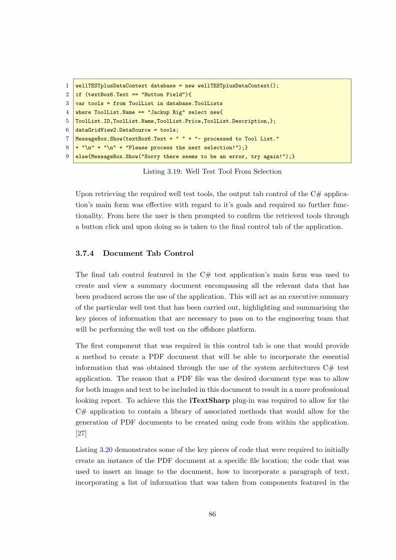
1 wellTESTplusDataContext database = new wellTESTplusDataContext();
2 if (textBox6.Text == "Hutton Field"){
3 var tools = from ToolList in database.ToolLists
4 where ToolList.Name == "Jackup Rig" select new{
5 ToolList.ID,ToolList.Name,ToolList.Price,ToolList.Description,};
6 dataGridView2.DataSource = tools;
7 MessageBox.Show(textBox6.Text + " " + "- processed to Tool List."
8 + "\n" + "\n" + "Please process the next selection!");}
9 else{MessageBox.Show("Sorry there seems to be an error, try again!");}
Listing 3.19: Well Test Tool From Selection
Upon retrieving the required well test tools, the output tab control of the C# applica-
tion’s main form was effective with regard to it’s goals and required no further func-
tionality. From here the user is then prompted to confirm the retrieved tools through
a button click and upon doing so is taken to the final control tab of the application.
3.7.4 Document Tab Control
The final tab control featured in the C# test application’s main form was used to
create and view a summary document encompassing all the relevant data that has
been produced across the use of the application. This will act as an executive summary
of the particular well test that has been carried out, highlighting and summarising the
key pieces of information that are necessary to pass on to the engineering team that
will be performing the well test on the offshore platform.
The first component that was required in this control tab is one that would provide
a method to create a PDF document that will be able to incorporate the essential
information that was obtained through the use of the system architectures C# test
application. The reason that a PDF file was the desired document type was to allow
for both images and text to be included in this document to result in a more professional
looking report. To achieve this the iTextSharp plug-in was required to allow for the
C# application to contain a library of associated methods that would allow for the
generation of PDF documents to be created using code from within the application.
[27]
Listing 3.20 demonstrates some of the key pieces of code that were required to initially
create an instance of the PDF document at a specific file location; the code that was
used to insert an image to the document, how to incorporate a paragraph of text,
incorporating a list of information that was taken from components featured in the
86
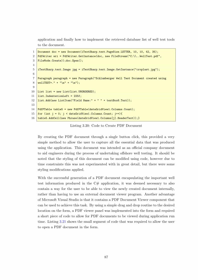
application and finally how to implement the retrieved database list of well test tools
to the document.
1 Document doc = new Document(iTextSharp.text.PageSize.LETTER, 10, 10, 42, 35);
2 PdfWriter wri = PdfWriter.GetInstance(doc, new FileStream("C:\\..WellTest.pdf",
3 FileMode.Create));doc.Open();
4
5 iTextSharp.text.Image jpg = iTextSharp.text.Image.GetInstance("croplast.jpg");
6
7 Paragraph paragraph = new Paragraph("Schlumberger Well Test Document created using
8 wellTEST+." + "\n" + "\n");
9
10 List list = new List(List.UNORDERED);
11 list.IndentationLeft = 225f;
12 list.Add(new ListItem("Field Name:" + " " + textBox6.Text));
13
14 PdfPTable table5 = new PdfPTable(dataGridView1.Columns.Count);
15 for (int j = 0; j < dataGridView1.Columns.Count; j++){
16 table5.AddCell(new Phrase(dataGridView1.Columns[j].HeaderText));}
Listing 3.20: Code to Create PDF Document
By creating the PDF document through a single button click, this provided a very
simple method to allow the user to capture all the essential data that was produced
using the application. This document was intended as an official company document
to aid engineers during the process of undertaking offshore well testing. It should be
noted that the styling of this document can be modified using code, however due to
time constraints this was not experimented with in great detail, but there were some
styling modifications applied.
With the successful generation of a PDF document encapsulating the important well
test information produced in the C# application, it was deemed necessary to also
contain a way for the user to be able to view the newly created document internally,
rather than having to use an external document viewer program. Another advantage
of Microsoft Visual Studio is that it contains a PDF Document Viewer component that
can be used to achieve this task. By using a simple drag and drop routine to the desired
location on the form, a PDF viewer panel was implemented into the form and required
a short piece of code to allow for PDF documents to be viewed during application run
time. Listing 3.21 shows the small segment of code that was required to allow the user
to open a PDF document in the form.
87
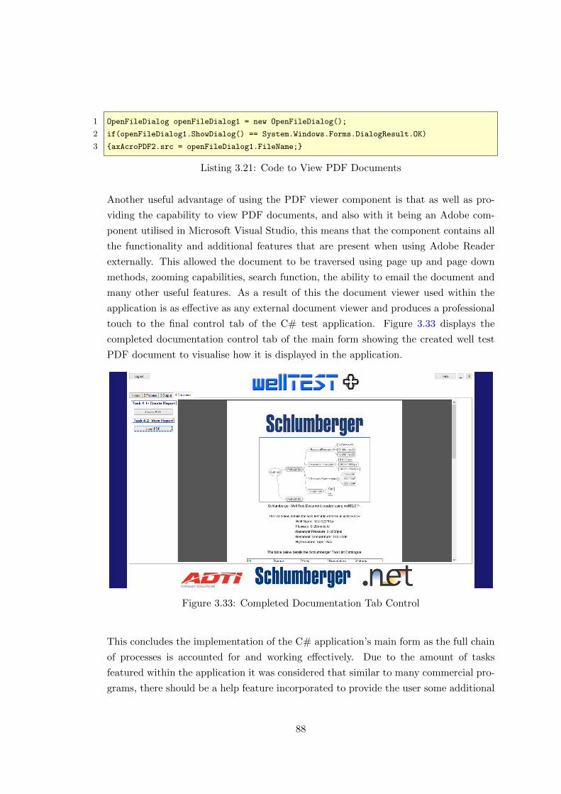
1 OpenFileDialog openFileDialog1 = new OpenFileDialog();
2 if(openFileDialog1.ShowDialog() == System.Windows.Forms.DialogResult.OK)
3 {axAcroPDF2.src = openFileDialog1.FileName;}
Listing 3.21: Code to View PDF Documents
Another useful advantage of using the PDF viewer component is that as well as pro-
viding the capability to view PDF documents, and also with it being an Adobe com-
ponent utilised in Microsoft Visual Studio, this means that the component contains all
the functionality and additional features that are present when using Adobe Reader
externally. This allowed the document to be traversed using page up and page down
methods, zooming capabilities, search function, the ability to email the document and
many other useful features. As a result of this the document viewer used within the
application is as effective as any external document viewer and produces a professional
touch to the final control tab of the C# test application. Figure 3.33 displays the
completed documentation control tab of the main form showing the created well test
PDF document to visualise how it is displayed in the application.
Figure 3.33: Completed Documentation Tab Control
This concludes the implementation of the C# application’s main form as the full chain
of processes is accounted for and working effectively. Due to the amount of tasks
featured within the application it was considered that similar to many commercial pro-
grams, there should be a help feature incorporated to provide the user some additional
88
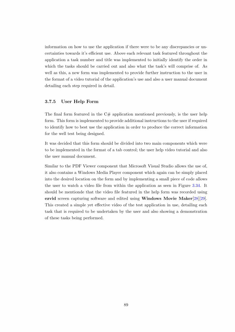
information on how to use the application if there were to be any discrepancies or un-
certainties towards it’s efficient use. Above each relevant task featured throughout the
application a task number and title was implemented to initially identify the order in
which the tasks should be carried out and also what the task’s will comprise of. As
well as this, a new form was implemented to provide further instruction to the user in
the format of a video tutorial of the application’s use and also a user manual document
detailing each step required in detail.
3.7.5 User Help Form
The final form featured in the C# application mentioned previously, is the user help
form. This form is implemented to provide additional instructions to the user if required
to identify how to best use the application in order to produce the correct information
for the well test being designed.
It was decided that this form should be divided into two main components which were
to be implemented in the format of a tab control; the user help video tutorial and also
the user manual document.
Similar to the PDF Viewer component that Microsoft Visual Studio allows the use of,
it also contains a Windows Media Player component which again can be simply placed
into the desired location on the form and by implementing a small piece of code allows
the user to watch a video file from within the application as seen in Figure 3.34. It
should be mentionde that the video file featured in the help form was recorded using
ezvid screen capturing software and edited using Windows Movie Maker[28][29].
This created a simple yet effective video of the test application in use, detailing each
task that is required to be undertaken by the user and also showing a demonstration
of these tasks being performed.
89
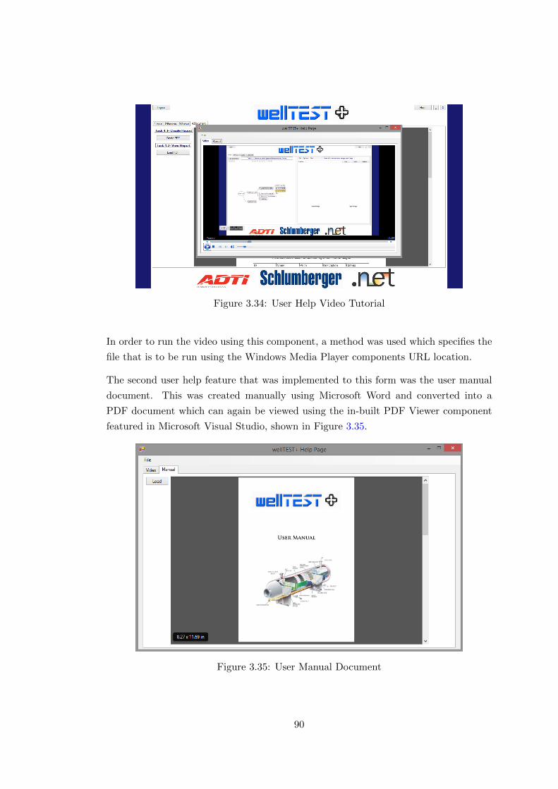
Figure 3.34: User Help Video Tutorial
In order to run the video using this component, a method was used which specifies the
file that is to be run using the Windows Media Player components URL location.
The second user help feature that was implemented to this form was the user manual
document. This was created manually using Microsoft Word and converted into a
PDF document which can again be viewed using the in-built PDF Viewer component
featured in Microsoft Visual Studio, shown in Figure 3.35.
Figure 3.35: User Manual Document
90
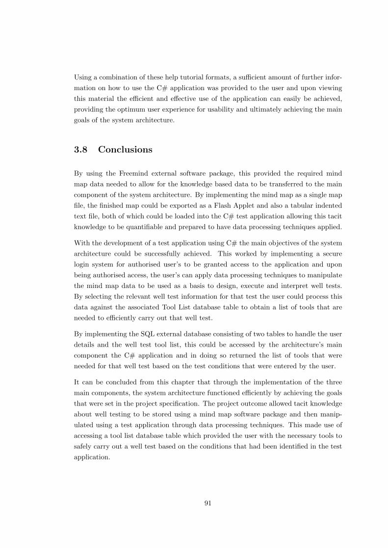
Using a combination of these help tutorial formats, a sufficient amount of further infor-
mation on how to use the C# application was provided to the user and upon viewing
this material the efficient and effective use of the application can easily be achieved,
providing the optimum user experience for usability and ultimately achieving the main
goals of the system architecture.
3.8 Conclusions
By using the Freemind external software package, this provided the required mind
map data needed to allow for the knowledge based data to be transferred to the main
component of the system architecture. By implementing the mind map as a single map
file, the finished map could be exported as a Flash Applet and also a tabular indented
text file, both of which could be loaded into the C# test application allowing this tacit
knowledge to be quantifiable and prepared to have data processing techniques applied.
With the development of a test application using C# the main objectives of the system
architecture could be successfully achieved. This worked by implementing a secure
login system for authorised user’s to be granted access to the application and upon
being authorised access, the user’s can apply data processing techniques to manipulate
the mind map data to be used as a basis to design, execute and interpret well tests.
By selecting the relevant well test information for that test the user could process this
data against the associated Tool List database table to obtain a list of tools that are
needed to efficiently carry out that well test.
By implementing the SQL external database consisting of two tables to handle the user
details and the well test tool list, this could be accessed by the architecture’s main
component the C# application and in doing so returned the list of tools that were
needed for that well test based on the test conditions that were entered by the user.
It can be concluded from this chapter that through the implementation of the three
main components, the system architecture functioned efficiently by achieving the goals
that were set in the project specification. The project outcome allowed tacit knowledge
about well testing to be stored using a mind map software package and then manip-
ulated using a test application through data processing techniques. This made use of
accessing a tool list database table which provided the user with the necessary tools to
safely carry out a well test based on the conditions that had been identified in the test
application.
91

Chapter 4
Evaluation & Testing
This chapter of the project implementation report provides evidence of the various
functional tests that were performed on the completed system architecture to ensure
that each of the implemented features work as they are expected to. Alongside the
testing of the architecture this chapter also shows the evaluation process that was
carried out to determine what the user thought of the architecture’s main component,
the C# application, to establish which aspects of it were effective and also what could
be improved.
4.1 Testing
This section details the testing that was carried out during the project implementation.
It was decided that black box testing was an effective method to be used to test the
functionality of the system architecture as it provides a solid overview of the main tasks
involved and what results were gained from the tests.
Each relevant test that is featured in this section contains the name of the test, a
description of the test, what the expected results of the test were and what the actual
results were. Using this process an understanding of the overall functionality of the
system architecture can be achieved, and any areas that need to be improved for future
development can be easily identified.
92
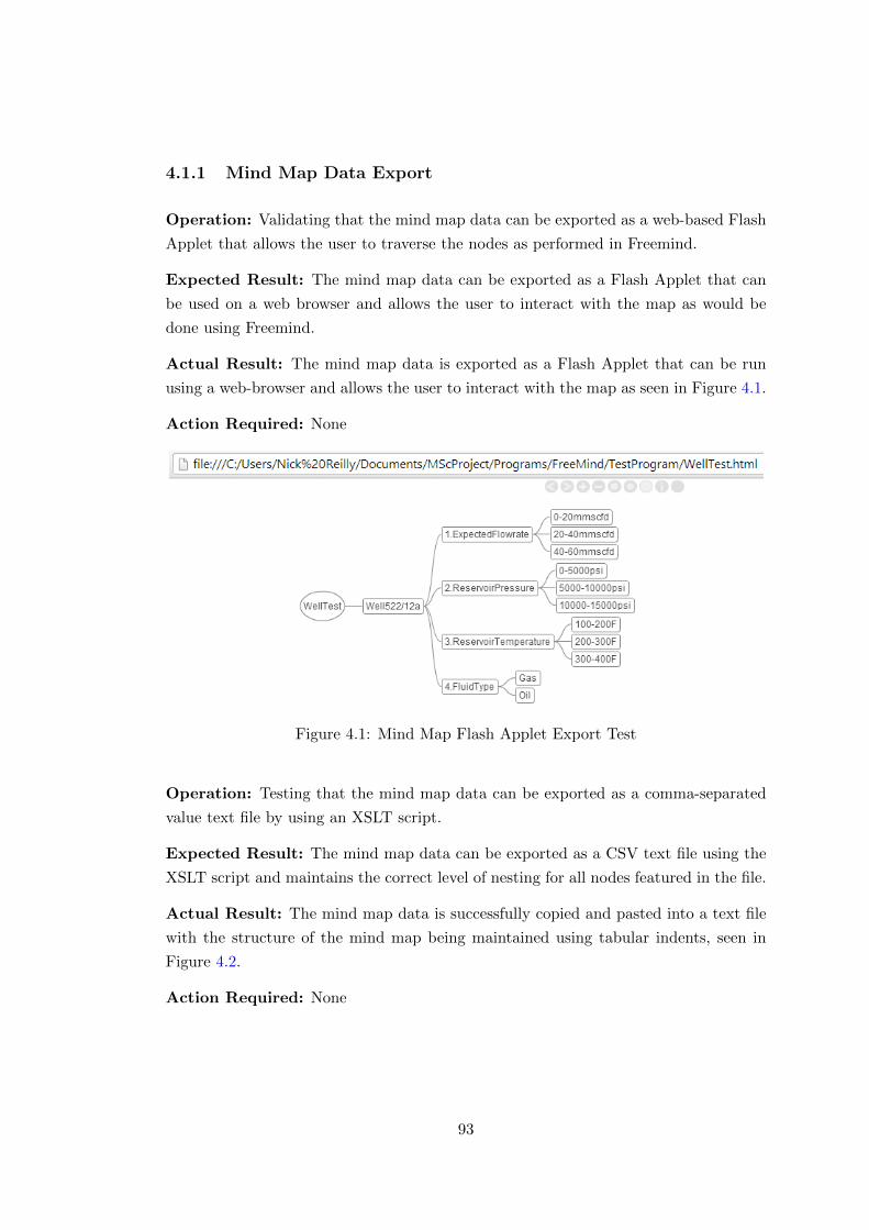
4.1.1 Mind Map Data Export
Operation: Validating that the mind map data can be exported as a web-based Flash
Applet that allows the user to traverse the nodes as performed in Freemind.
Expected Result: The mind map data can be exported as a Flash Applet that can
be used on a web browser and allows the user to interact with the map as would be
done using Freemind.
Actual Result: The mind map data is exported as a Flash Applet that can be run
using a web-browser and allows the user to interact with the map as seen in Figure 4.1.
Action Required: None
Figure 4.1: Mind Map Flash Applet Export Test
Operation: Testing that the mind map data can be exported as a comma-separated
value text file by using an XSLT script.
Expected Result: The mind map data can be exported as a CSV text file using the
XSLT script and maintains the correct level of nesting for all nodes featured in the file.
Actual Result: The mind map data is successfully copied and pasted into a text file
with the structure of the mind map being maintained using tabular indents, seen in
Figure 4.2.
Action Required: None
93
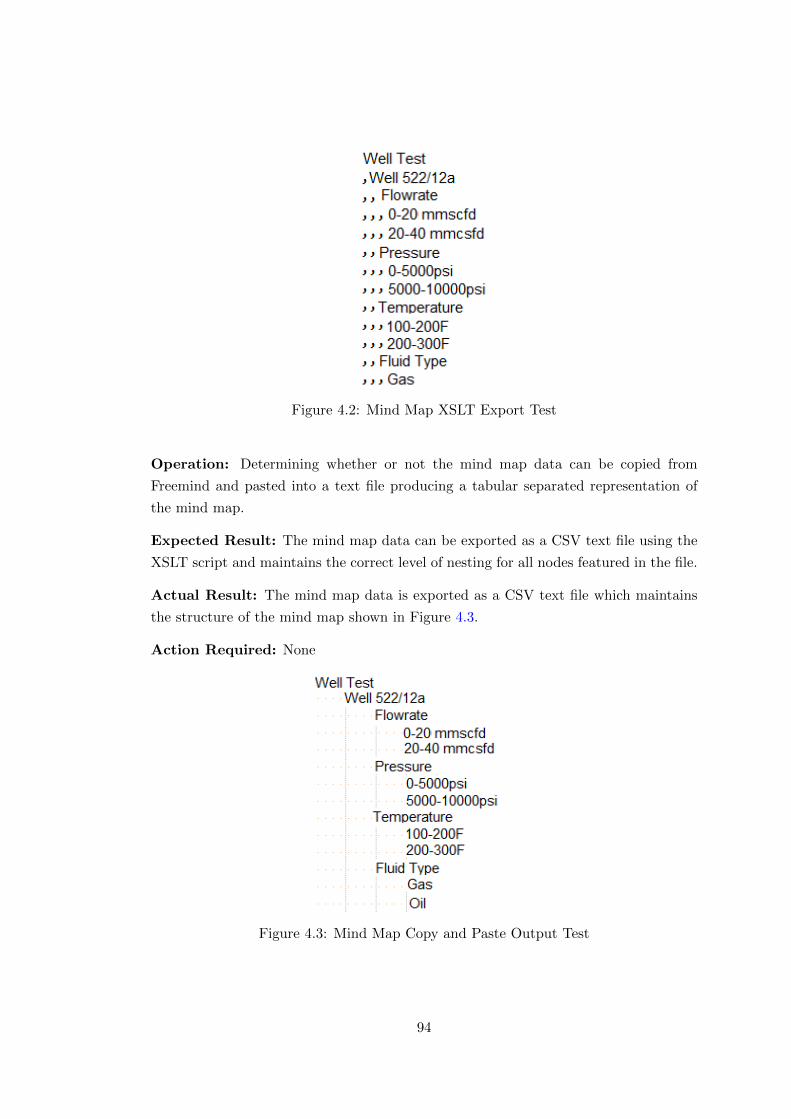
Figure 4.2: Mind Map XSLT Export Test
Operation: Determining whether or not the mind map data can be copied from
Freemind and pasted into a text file producing a tabular separated representation of
the mind map.
Expected Result: The mind map data can be exported as a CSV text file using the
XSLT script and maintains the correct level of nesting for all nodes featured in the file.
Actual Result: The mind map data is exported as a CSV text file which maintains
the structure of the mind map shown in Figure 4.3.
Action Required: None
Figure 4.3: Mind Map Copy and Paste Output Test
94
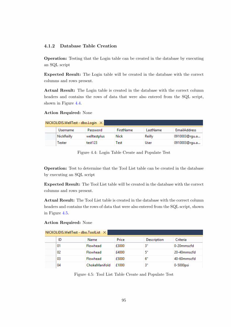
4.1.2 Database Table Creation
Operation: Testing that the Login table can be created in the database by executing
an SQL script
Expected Result: The Login table will be created in the database with the correct
columns and rows present.
Actual Result: The Login table is created in the database with the correct column
headers and contains the rows of data that were also entered from the SQL script,
shown in Figure 4.4.
Action Required: None
Figure 4.4: Login Table Create and Populate Test
Operation: Test to determine that the Tool List table can be created in the database
by executing an SQL script
Expected Result: The Tool List table will be created in the database with the correct
columns and rows present.
Actual Result: The Tool List table is created in the database with the correct column
headers and contains the rows of data that were also entered from the SQL script, shown
in Figure 4.5.
Action Required: None
Figure 4.5: Tool List Table Create and Populate Test
95

4.1.3 Resolution Display
Operation: Ensuring the form loads to the size of the screen and maintains its reso-
lution across a variety of screen sizes.
Expected Result: The form will load to an aspect ratio that matches the resolution
of the device’s screen.
Actual Result: The form loads to an aspect ratio that matches the resolution of the
device’s screen as seen in Figure 4.6, this is validated by no windows controls being
visible around the form.
Action Required: None
Figure 4.6: Screen Resolution Test
4.1.4 Custom Form Handling Controls
Operation: Testing the custom form handling controls to achieve the desired tasks.
Expected Result: The custom controls will allow the user to minimise, maximise
and restore, close and also re-position the form through mouse operations.
Actual Result: The custom controls, seen in Figure 4.7, allow the user to minimise,
maximise and restore, close and also re-position the form.
Action Required: None
Figure 4.7: Custom Control Functionality Test
96
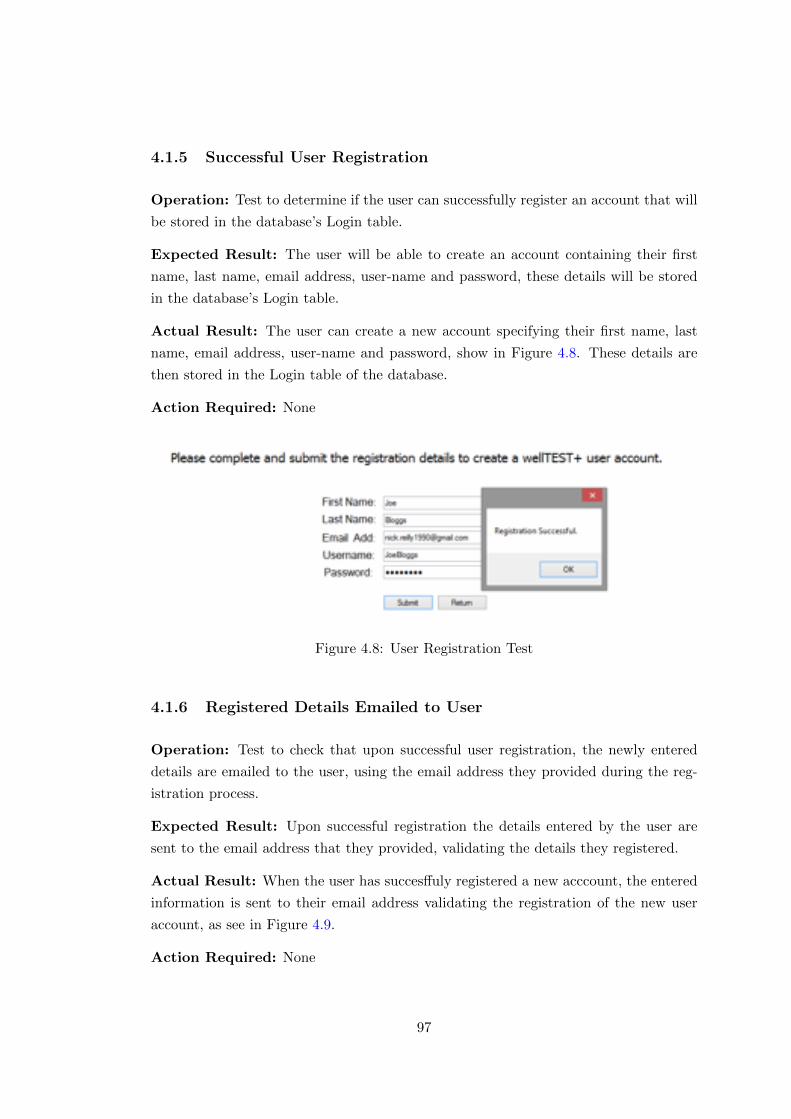
4.1.5 Successful User Registration
Operation: Test to determine if the user can successfully register an account that will
be stored in the database’s Login table.
Expected Result: The user will be able to create an account containing their first
name, last name, email address, user-name and password, these details will be stored
in the database’s Login table.
Actual Result: The user can create a new account specifying their first name, last
name, email address, user-name and password, show in Figure 4.8. These details are
then stored in the Login table of the database.
Action Required: None
Figure 4.8: User Registration Test
4.1.6 Registered Details Emailed to User
Operation: Test to check that upon successful user registration, the newly entered
details are emailed to the user, using the email address they provided during the reg-
istration process.
Expected Result: Upon successful registration the details entered by the user are
sent to the email address that they provided, validating the details they registered.
Actual Result: When the user has succesffuly registered a new acccount, the entered
information is sent to their email address validating the registration of the new user
account, as see in Figure 4.9.
Action Required: None
97
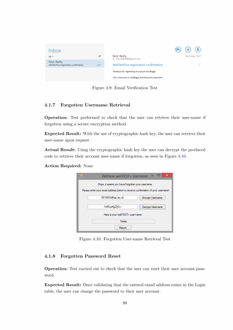
Figure 4.9: Email Verification Test
4.1.7 Forgotten Username Retrieval
Operation: Test performed to check that the user can retrieve their user-name if
forgotten using a secure encryption method.
Expected Result: With the use of cryptographic hash key, the user can retrieve their
user-name upon request.
Actual Result: Using the cryptographic hash key the user can decrypt the produced
code to retrieve their account user-name if forgotten, as seen in Figure 4.10.
Action Required: None
Figure 4.10: Forgotten User-name Retrieval Test
4.1.8 Forgotten Password Reset
Operation: Test carried out to check that the user can reset their user account pass-
word.
Expected Result: Once validating that the entered email address exists in the Login
table, the user can change the password to their user account.
98
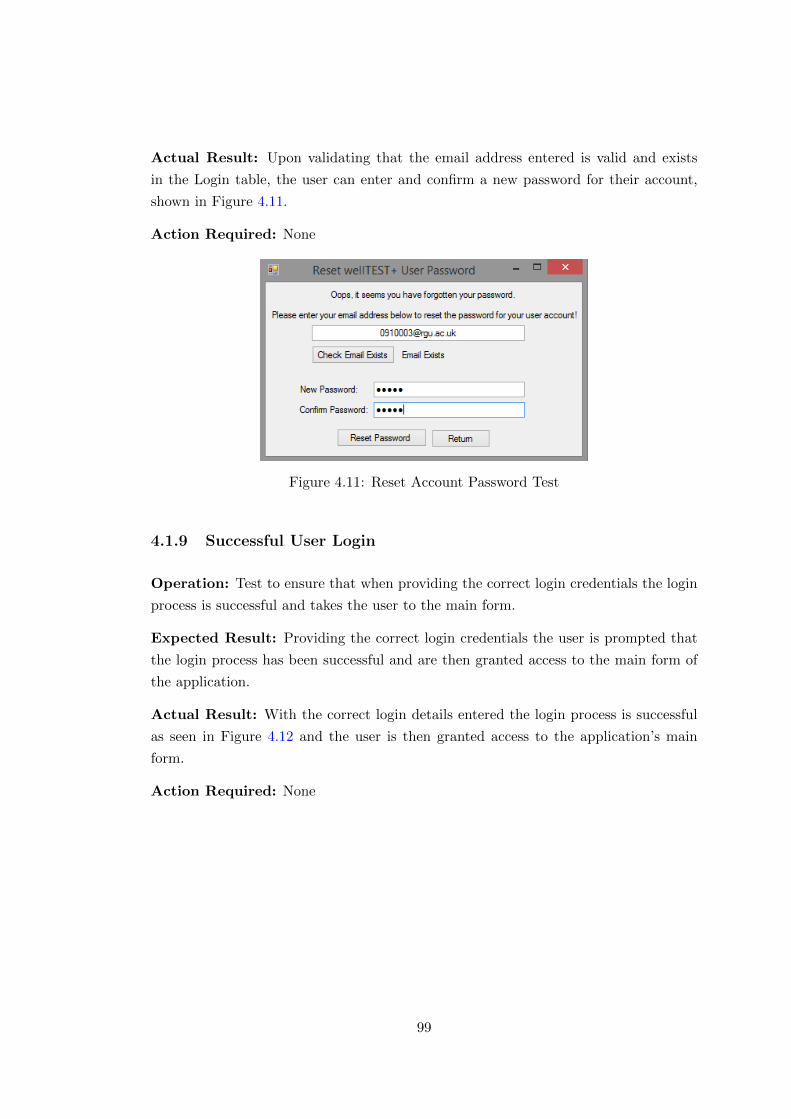
Actual Result: Upon validating that the email address entered is valid and exists
in the Login table, the user can enter and confirm a new password for their account,
shown in Figure 4.11.
Action Required: None
Figure 4.11: Reset Account Password Test
4.1.9 Successful User Login
Operation: Test to ensure that when providing the correct login credentials the login
process is successful and takes the user to the main form.
Expected Result: Providing the correct login credentials the user is prompted that
the login process has been successful and are then granted access to the main form of
the application.
Actual Result: With the correct login details entered the login process is successful
as seen in Figure 4.12 and the user is then granted access to the application’s main
form.
Action Required: None
99

Figure 4.12: User Login Test
4.1.10 Internal Display of Mind Map Flash Applet
Operation: Ensuring that when the main form of the application is opened the mind
map Flash Applet file is loaded and displayed within the application.
Expected Result: When the main form is opened by the user, the web browser
component should load the mind map Flash Applet and allow the user to interact with
the map as would be done externally.
Actual Result: Once the main form is opened the web browser component successfully
loads the mind map Flash Applet and provides the necessary interactivity to use the
map as it would be done internally, shown in Figure 4.13.
Action Required: None
100
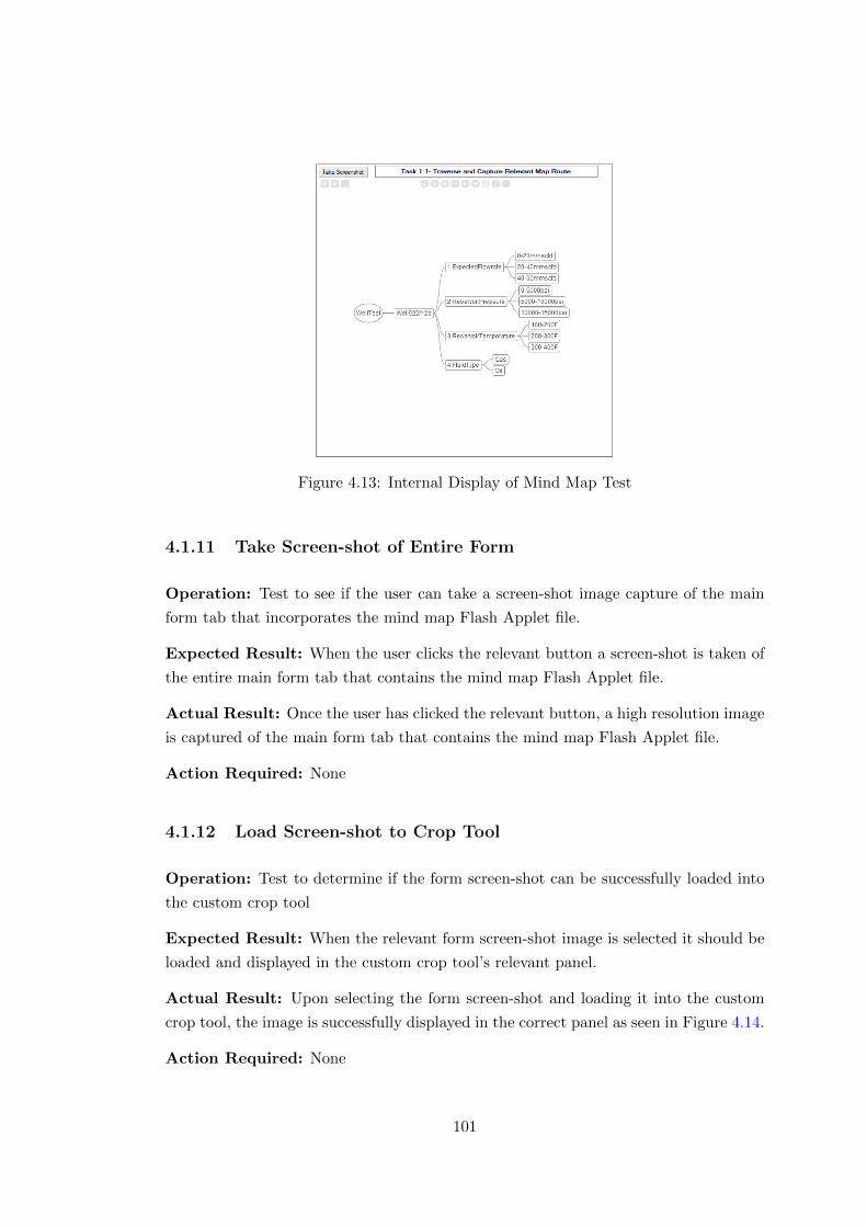
Figure 4.13: Internal Display of Mind Map Test
4.1.11 Take Screen-shot of Entire Form
Operation: Test to see if the user can take a screen-shot image capture of the main
form tab that incorporates the mind map Flash Applet file.
Expected Result: When the user clicks the relevant button a screen-shot is taken of
the entire main form tab that contains the mind map Flash Applet file.
Actual Result: Once the user has clicked the relevant button, a high resolution image
is captured of the main form tab that contains the mind map Flash Applet file.
Action Required: None
4.1.12 Load Screen-shot to Crop Tool
Operation: Test to determine if the form screen-shot can be successfully loaded into
the custom crop tool
Expected Result: When the relevant form screen-shot image is selected it should be
loaded and displayed in the custom crop tool’s relevant panel.
Actual Result: Upon selecting the form screen-shot and loading it into the custom
crop tool, the image is successfully displayed in the correct panel as seen in Figure 4.14.
Action Required: None
101
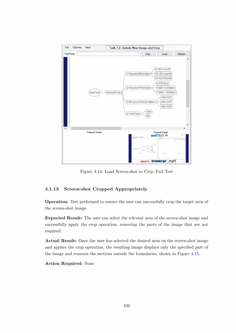
Figure 4.14: Load Screen-shot to Crop Tool Test
4.1.13 Screen-shot Cropped Appropriately
Operation: Test performed to ensure the user can successfully crop the target area of
the screen-shot image.
Expected Result: The user can select the relevant area of the screen-shot image and
successfully apply the crop operation, removing the parts of the image that are not
required.
Actual Result: Once the user has selected the desired area on the screen-shot image
and applies the crop operation, the resulting image displays only the specified part of
the image and removes the sections outside the boundaries, shown in Figure 4.15.
Action Required: None
102
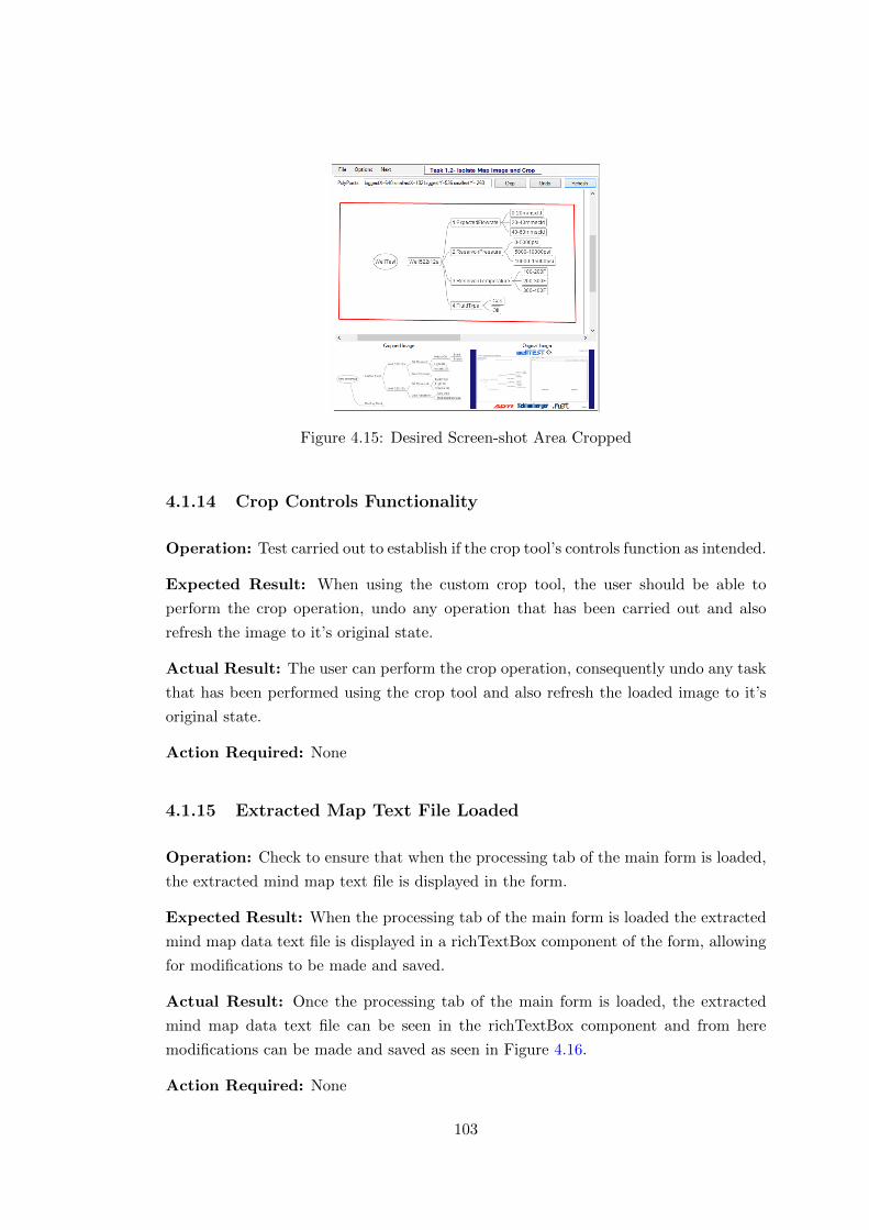
Figure 4.15: Desired Screen-shot Area Cropped
4.1.14 Crop Controls Functionality
Operation: Test carried out to establish if the crop tool’s controls function as intended.
Expected Result: When using the custom crop tool, the user should be able to
perform the crop operation, undo any operation that has been carried out and also
refresh the image to it’s original state.
Actual Result: The user can perform the crop operation, consequently undo any task
that has been performed using the crop tool and also refresh the loaded image to it’s
original state.
Action Required: None
4.1.15 Extracted Map Text File Loaded
Operation: Check to ensure that when the processing tab of the main form is loaded,
the extracted mind map text file is displayed in the form.
Expected Result: When the processing tab of the main form is loaded the extracted
mind map data text file is displayed in a richTextBox component of the form, allowing
for modifications to be made and saved.
Actual Result: Once the processing tab of the main form is loaded, the extracted
mind map data text file can be seen in the richTextBox component and from here
modifications can be made and saved as seen in Figure 4.16.
Action Required: None
103
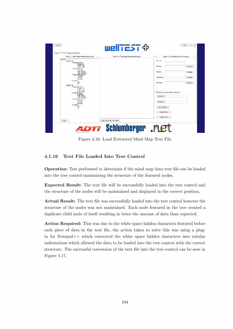
Figure 4.16: Load Extracted Mind Map Text File
4.1.16 Text File Loaded Into Tree Control
Operation: Test performed to determine if the mind map data text file can be loaded
into the tree control maintaining the structure of the featured nodes.
Expected Result: The text file will be successfully loaded into the tree control and
the structure of the nodes will be maintained and displayed in the correct position.
Actual Result: The text file was successfully loaded into the tree control however the
structure of the nodes was not maintained. Each node featured in the tree created a
duplicate child node of itself resulting in twice the amount of data than expected.
Action Required: This was due to the white space hidden characters featured before
each piece of data in the text file, the action taken to solve this was using a plug-
in for Notepad++ which converted the white space hidden characters into tabular
indentations which allowed the data to be loaded into the tree control with the correct
structure. The successful conversion of the text file into the tree control can be seen in
Figure 4.17.
104
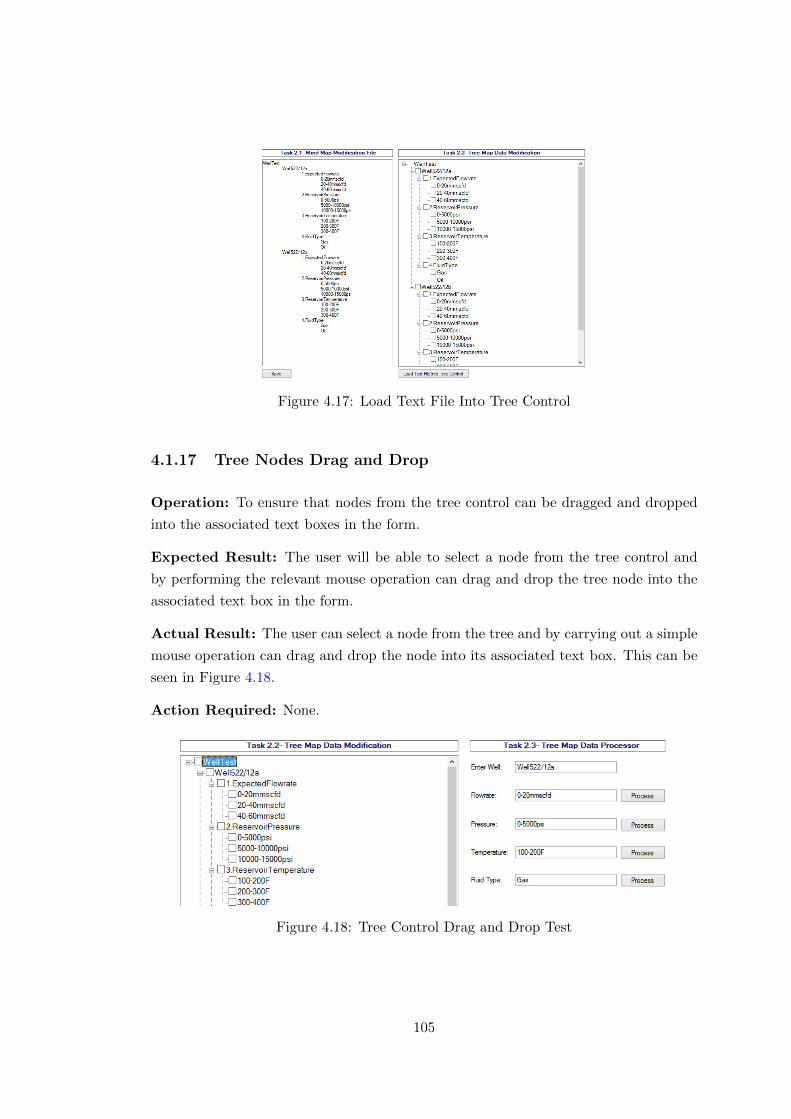
Figure 4.17: Load Text File Into Tree Control
4.1.17 Tree Nodes Drag and Drop
Operation: To ensure that nodes from the tree control can be dragged and dropped
into the associated text boxes in the form.
Expected Result: The user will be able to select a node from the tree control and
by performing the relevant mouse operation can drag and drop the tree node into the
associated text box in the form.
Actual Result: The user can select a node from the tree and by carrying out a simple
mouse operation can drag and drop the node into its associated text box. This can be
seen in Figure 4.18.
Action Required: None.
Figure 4.18: Tree Control Drag and Drop Test
105
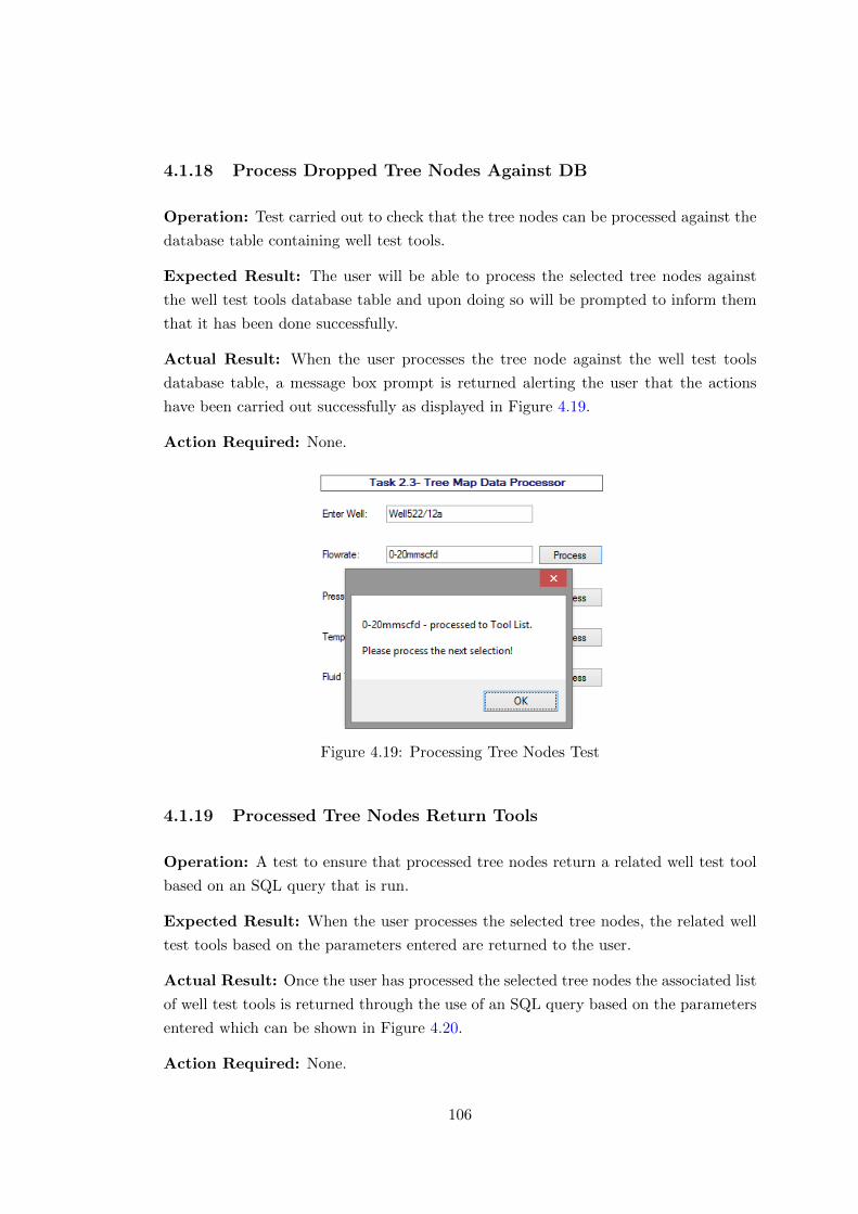
4.1.18 Process Dropped Tree Nodes Against DB
Operation: Test carried out to check that the tree nodes can be processed against the
database table containing well test tools.
Expected Result: The user will be able to process the selected tree nodes against
the well test tools database table and upon doing so will be prompted to inform them
that it has been done successfully.
Actual Result: When the user processes the tree node against the well test tools
database table, a message box prompt is returned alerting the user that the actions
have been carried out successfully as displayed in Figure 4.19.
Action Required: None.
Figure 4.19: Processing Tree Nodes Test
4.1.19 Processed Tree Nodes Return Tools
Operation: A test to ensure that processed tree nodes return a related well test tool
based on an SQL query that is run.
Expected Result: When the user processes the selected tree nodes, the related well
test tools based on the parameters entered are returned to the user.
Actual Result: Once the user has processed the selected tree nodes the associated list
of well test tools is returned through the use of an SQL query based on the parameters
entered which can be shown in Figure 4.20.
Action Required: None.
106
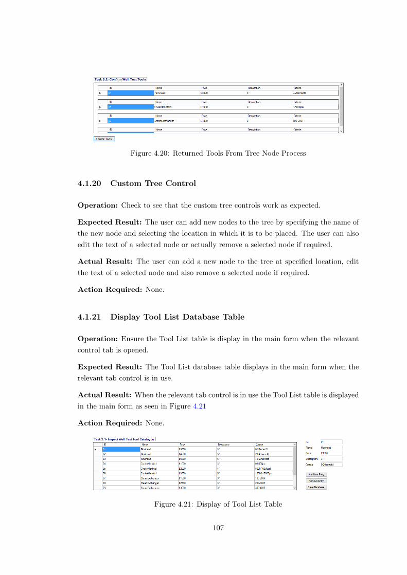
Figure 4.20: Returned Tools From Tree Node Process
4.1.20 Custom Tree Control
Operation: Check to see that the custom tree controls work as expected.
Expected Result: The user can add new nodes to the tree by specifying the name of
the new node and selecting the location in which it is to be placed. The user can also
edit the text of a selected node or actually remove a selected node if required.
Actual Result: The user can add a new node to the tree at specified location, edit
the text of a selected node and also remove a selected node if required.
Action Required: None.
4.1.21 Display Tool List Database Table
Operation: Ensure the Tool List table is display in the main form when the relevant
control tab is opened.
Expected Result: The Tool List database table displays in the main form when the
relevant tab control is in use.
Actual Result: When the relevant tab control is in use the Tool List table is displayed
in the main form as seen in Figure 4.21
Action Required: None.
Figure 4.21: Display of Tool List Table
107
4.1.22 Add, Remove, Save Database Entries
Operation: Test to check the user can add, remove and save database entries in the
application.
Expected Result: The user will be able to add new entries into the database table,
remove an entry from the table and update the modifications to the database table as
required. All these changes should be saved frequently.
Actual Result: The user can add a new entry to the database table, remove an
entry and also save/update the modifications made to the table. All changes are saved
frequently.
Action Required: None.
4.1.23 Creation of PDF Document
Operation: Determine if the user can create a PDF document detailing the important
information produced using the C# application.
Expected Result: Upon clicking the ‘Create PDF’ button a message box prompt will
be shown to the user confirming whether the creation of the PDF document has been
successful, encapsulating the relevant information produced using the C# application.
Actual Result: When clicking the ‘Create PDF’ button the message box prompt
displays that the generation of the PDF has been successful, meaning all the relevant
information has been captured and incorporated into the PDF document.
Action Required: None.
4.1.24 View Created PDF Document
Operation: Test carried out to check if the user can view the created PDF document.
Expected Result: The user will be able to load the created Well Test PDF document
and view it using the PDF viewer.
Actual Result: When the user loads the well test PDF document in the C# appli-
cations main form using the PDF viewer, the document is opened and can be viewed,
shown in Figure 4.22.
Action Required: None.
108
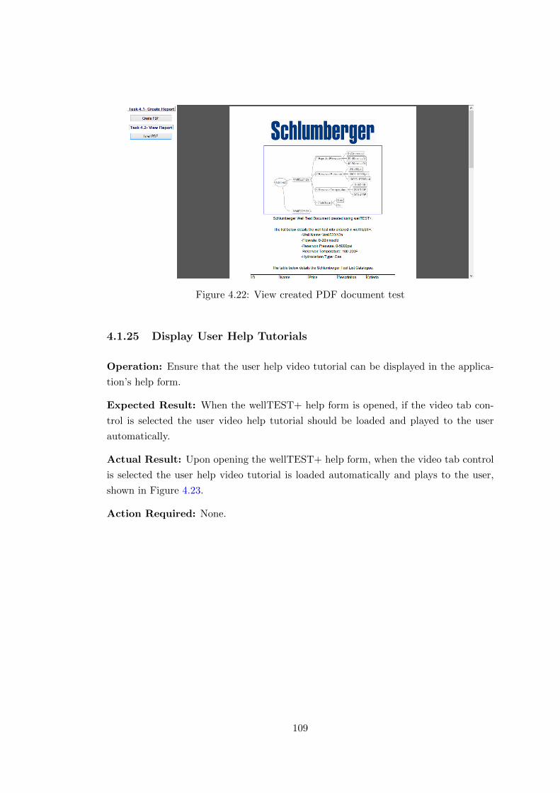
Figure 4.22: View created PDF document test
4.1.25 Display User Help Tutorials
Operation: Ensure that the user help video tutorial can be displayed in the applica-
tion’s help form.
Expected Result: When the wellTEST+ help form is opened, if the video tab con-
trol is selected the user video help tutorial should be loaded and played to the user
automatically.
Actual Result: Upon opening the wellTEST+ help form, when the video tab control
is selected the user help video tutorial is loaded automatically and plays to the user,
shown in Figure 4.23.
Action Required: None.
109
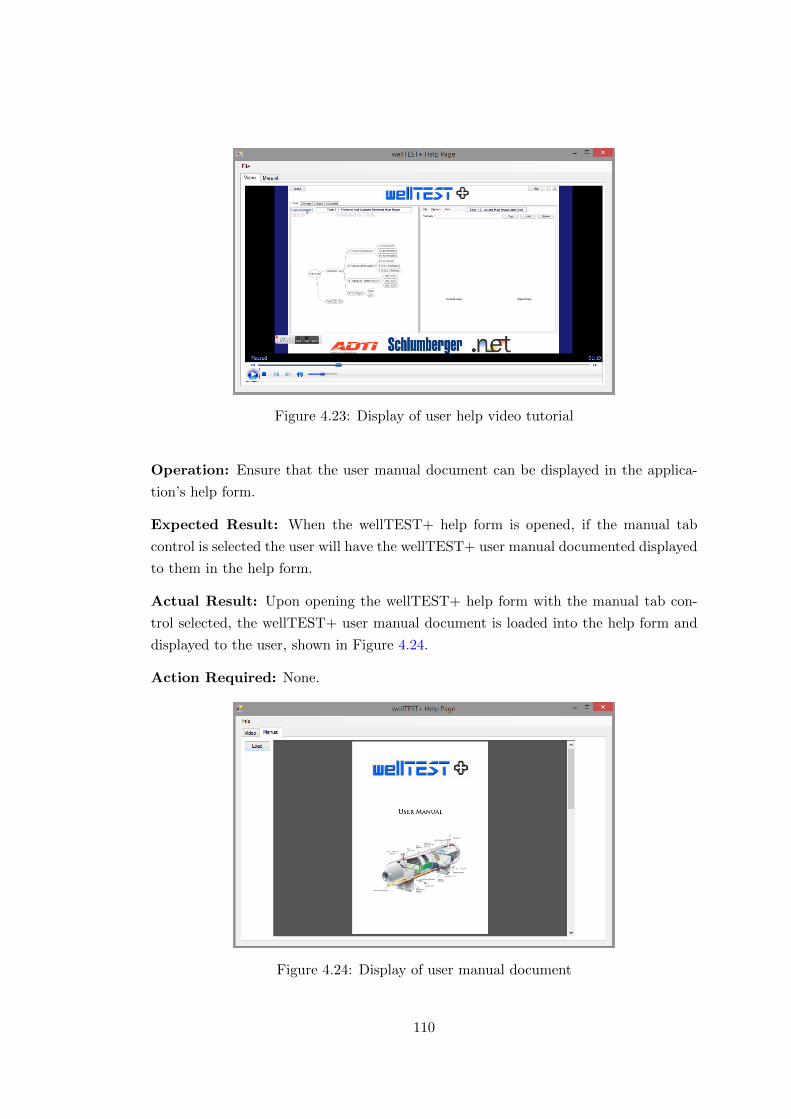
Figure 4.23: Display of user help video tutorial
Operation: Ensure that the user manual document can be displayed in the applica-
tion’s help form.
Expected Result: When the wellTEST+ help form is opened, if the manual tab
control is selected the user will have the wellTEST+ user manual documented displayed
to them in the help form.
Actual Result: Upon opening the wellTEST+ help form with the manual tab con-
trol selected, the wellTEST+ user manual document is loaded into the help form and
displayed to the user, shown in Figure 4.24.
Action Required: None.
Figure 4.24: Display of user manual document
110

4.2 Evaluation
In order to evaluate the usability of the system architecture, in particular the C# test
application which the user would carry out their tasks on, a usability questionnaire
was created to identify what experience the user had. This consisted of ten questions
that addressed important criteria which would determine the overall usability of the
application and to establish whether the user’s found it efficient. The questions included
in the survey are as follows:
1. Was the application intuitive?
2. Was the application easy to use?
3. Were the tasks featured in the application easy to identify?
4. Was everything structured in a logical manner?
5. Was the style and incorporation of graphics used effectively?
6. Was there a suitable balance between graphics and information?
7. Did the application allow you to achieve your goals?
8. Did the application increase the time take to design a well test?
9. Was the colour scheme used effective?
10. Would you use the application again?
Each of the questions that were asked in the evaluation survey could be answered with
one of the following options; Strongly Disagree, Disagree, Agree or Strongly Agree.
To convert these answers into a quantifiable measure, the options were assigned with a
numerical value from one to four. One being used as the value for Strongly Disagree and
four being used as the value for Strongly Agree. Using these numerical values obtained
from the answers given in the evaluation questionnaire, two graphs were produced to
display the overall feedback that was given and from this the aspects of the application
that user’s found helpful or not helpful could be easily identified.
The questionnaire was completed by a small focus group of ten engineers from ADTi
with a varying range of computing skills to ensure that the feedback given was bal-
anced and provided relevant results which could be used to identify the aspects of the
application which were positive and any aspects that could be improved in a future
development.
111
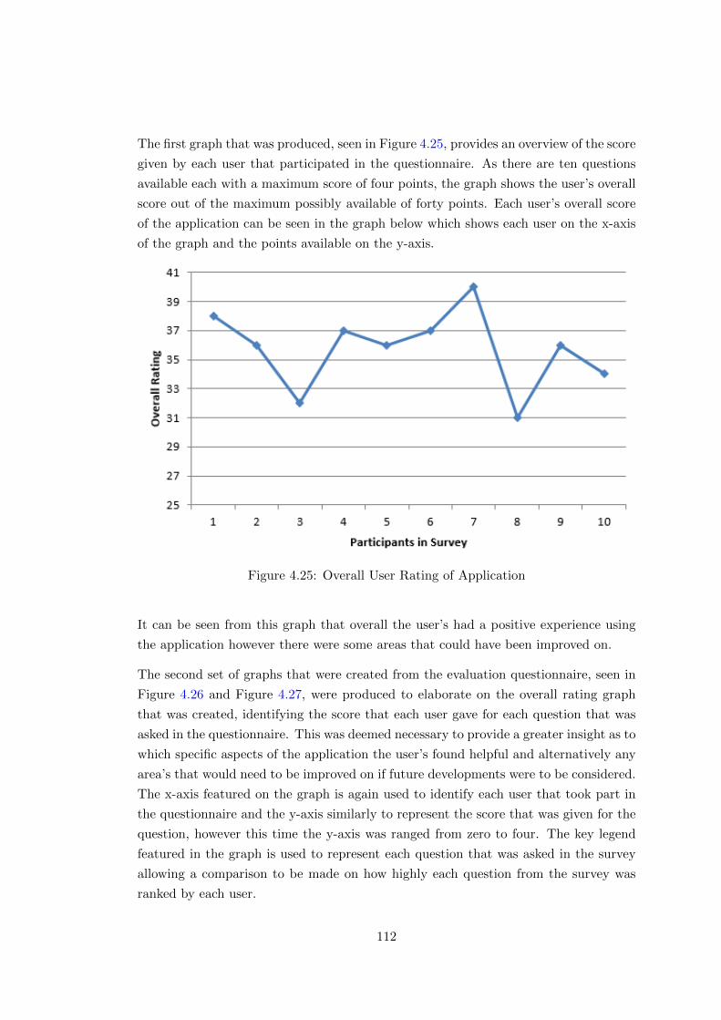
The first graph that was produced, seen in Figure 4.25, provides an overview of the score
given by each user that participated in the questionnaire. As there are ten questions
available each with a maximum score of four points, the graph shows the user’s overall
score out of the maximum possibly available of forty points. Each user’s overall score
of the application can be seen in the graph below which shows each user on the x-axis
of the graph and the points available on the y-axis.
Figure 4.25: Overall User Rating of Application
It can be seen from this graph that overall the user’s had a positive experience using
the application however there were some areas that could have been improved on.
The second set of graphs that were created from the evaluation questionnaire, seen in
Figure 4.26 and Figure 4.27, were produced to elaborate on the overall rating graph
that was created, identifying the score that each user gave for each question that was
asked in the questionnaire. This was deemed necessary to provide a greater insight as to
which specific aspects of the application the user’s found helpful and alternatively any
area’s that would need to be improved on if future developments were to be considered.
The x-axis featured on the graph is again used to identify each user that took part in
the questionnaire and the y-axis similarly to represent the score that was given for the
question, however this time the y-axis was ranged from zero to four. The key legend
featured in the graph is used to represent each question that was asked in the survey
allowing a comparison to be made on how highly each question from the survey was
ranked by each user.
112
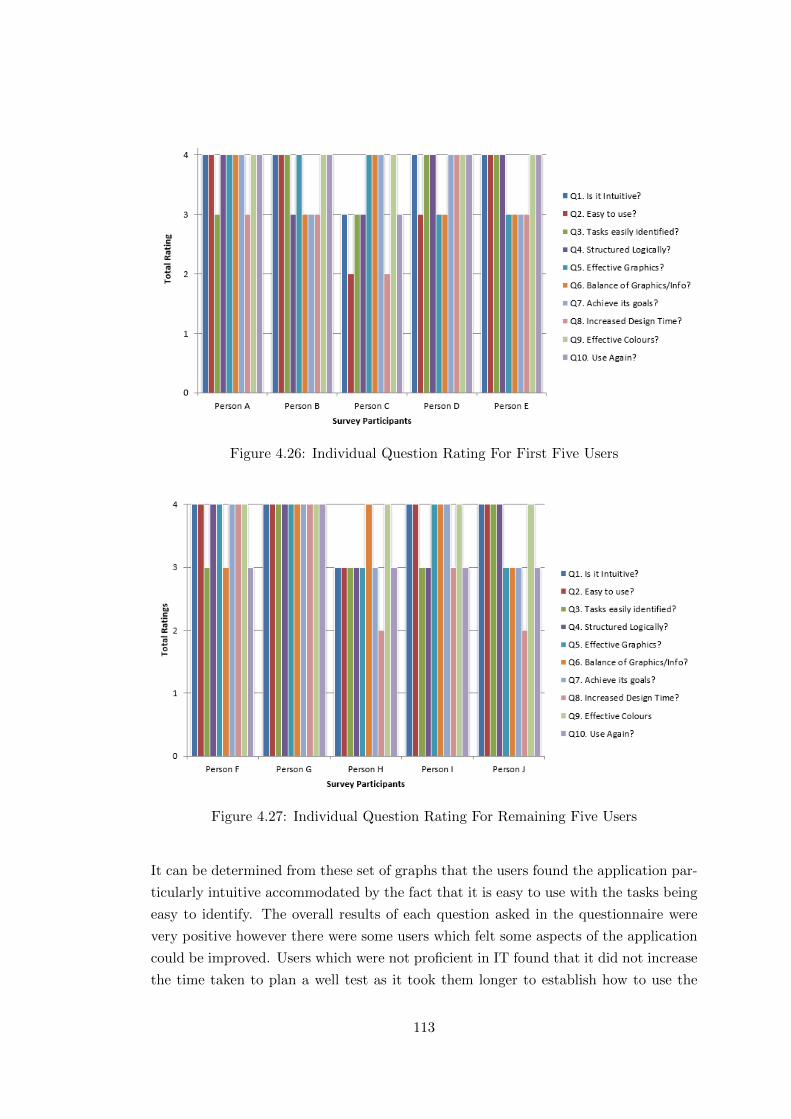
Figure 4.26: Individual Question Rating For First Five Users
Figure 4.27: Individual Question Rating For Remaining Five Users
It can be determined from these set of graphs that the users found the application par-
ticularly intuitive accommodated by the fact that it is easy to use with the tasks being
easy to identify. The overall results of each question asked in the questionnaire were
very positive however there were some users which felt some aspects of the application
could be improved. Users which were not proficient in IT found that it did not increase
the time taken to plan a well test as it took them longer to establish how to use the
113
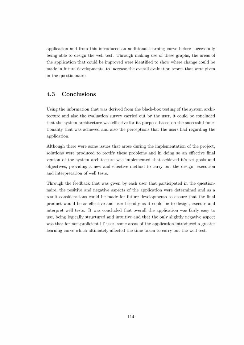
application and from this introduced an additional learning curve before successfully
being able to design the well test. Through making use of these graphs, the areas of
the application that could be improved were identified to show where change could be
made in future developments, to increase the overall evaluation scores that were given
in the questionnaire.
4.3 Conclusions
Using the information that was derived from the black-box testing of the system archi-
tecture and also the evaluation survey carried out by the user, it could be concluded
that the system architecture was effective for its purpose based on the successful func-
tionality that was achieved and also the perceptions that the users had regarding the
application.
Although there were some issues that arose during the implementation of the project,
solutions were produced to rectify these problems and in doing so an effective final
version of the system architecture was implemented that achieved it’s set goals and
objectives, providing a new and effective method to carry out the design, execution
and interpretation of well tests.
Through the feedback that was given by each user that participated in the question-
naire, the positive and negative aspects of the application were determined and as a
result considerations could be made for future developments to ensure that the final
product would be as effective and user friendly as it could be to design, execute and
interpret well tests. It was concluded that overall the application was fairly easy to
use, being logically structured and intuitive and that the only slightly negative aspect
was that for non-proficient IT user, some areas of the application introduced a greater
learning curve which ultimately affected the time taken to carry out the well test.
114
Chapter 5
Conclusion
This chapter summarises the main outcomes and conclusions that were obtained
throughout the duration of the project implementation phase. This covers all the rel-
evant tasks and activities that were involved to reach the final outcome of the project
and is used to determine whether or not the project was deemed a success.
5.1 Conclusions
Through the work that was undertaken it can be concluded that ultimately the project
was successful in that the end product achieved all the goals and objectives that were
set as project specifications. This encompassed the relevant design considerations that
were made, the extensive developmental component testing that was carried out to
establish the best methods available to achieve the important tasks required and also
the effective implementation of the system architecture itself.
Although there were some development issues faced during the implementation, effec-
tive solutions were established to address these problems and as a result this ensured
that the components comprising the system architecture functioned as intended. This
allowed for the successful flow of data to be maintained throughout each component
in the system architecture, ultimately ensuring that the desired outcome to allow the
user to design, execute and interpret a safe well test was achieved.
Despite the current software solutions that are available for well testing in the Oil and
Gas industry, it was noted that these solutions are effective mainly for the interpretation
of data obtained from a live well test, however no such software solution has yet been
implemented to aid the design and execution of well tests. Due to this it means that the
115
system architecture implemented in this project is a novel approach, which if utilised
properly could change the way in which current well testing processes are carried out,
resulting in a safer and more efficient design and execution process which documents
the information needed whilst also improving the time in which these tests can be
performed.
With these factors in mind it was concluded from this project that an effective system
architecture was implemented making use of an unorthodox knowledge base data store,
a current industry standard application development environment and also a secure
back end database which accommodates the efficient storage and access of sensitive
data. This project demonstrated a new approach to implement industry standard best
practice in the design, execution and interpretation of well tests.
5.2 Future Work
This section of the conclusion chapter details any considerations that have been made
towards future developments of the system architecture.
The main aspect of the system architecture which could be improved in future devel-
opments would be to adapt and extend the data that is used to design, execute and
interpret a well test. Due to time constraints only a small string of well test information
could be accounted for as the practice of well testing is very large and has many param-
eters which determine the overall decision of how to perform a successful test. With
the adaptation of the data featured in the architecture, this would result in a more
comprehensive end product which can provide accurate results across a vast quantity
of different well test conditions and affecting factors.
Again due to time constraints one feature of the system architecture could not be
implemented that was originally proposed as part of the project specification. Although
the design concept of this was created, the implementation of a .NET plug-in structure
was not incorporated into the final product. This omission creates a student project
opportunity for future collaboration with Schlumberger to develop this further. The
original source code could be extended to accommodate a vast range of well testing
processes that are frequently performed in the Oil and Gas industry.
116
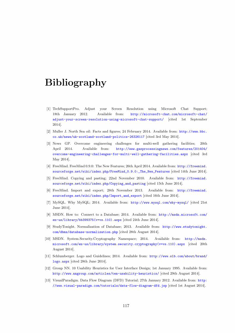
Bibliography
[1] TechSupportPro. Adjust your Screen Resolution using Microsoft Chat Support;
18th January 2012. Available from: http://microsoft-chat.com/microsoft-chat/
adjust-your-screen-resolution-using-microsoft-chat-support/ [cited 1st September
2014].
[2] Muller J. North Sea oil: Facts and figures; 24 February 2014. Available from: http://www.bbc.
co.uk/news/uk-scotland-scotland-politics-26326117 [cited 3rd May 2014].
[3] News GP. Overcome engineering challenges for multi-well gathering facilities; 20th
April 2014. Available from: http://www.gasprocessingnews.com/features/201404/
overcome-engineering-challenges-for-multi-well-gathering-facilities.aspx [cited 3rd
May 2014].
[4] FreeMind. FreeMind 0.9.0: The New Features; 26th April 2014. Available from: http://freemind.
sourceforge.net/wiki/index.php/FreeMind_0.9.0:_The_New_Features [cited 14th June 2014].
[5] FreeMind. Copying and pasting; 22nd November 2010. Available from: http://freemind.
sourceforge.net/wiki/index.php/Copying_and_pasting [cited 15th June 2014].
[6] FreeMind. Import and export; 28th November 2013. Available from: http://freemind.
sourceforge.net/wiki/index.php/Import_and_export [cited 16th June 2014].
[7] MySQL. Why MySQL; 2014. Available from: http://www.mysql.com/why-mysql/ [cited 21st
June 2014].
[8] MSDN. How to: Connect to a Database; 2014. Available from: http://msdn.microsoft.com/
en-us/library/bb399375(v=vs.110).aspx [cited 24th June 2014].
[9] StudyTonight. Normalization of Database; 2013. Available from: http://www.studytonight.
com/dbms/database-normalization.php [cited 28th August 2014].
[10] MSDN. System.Security.Cryptography Namespace; 2014. Available from: http://msdn.
microsoft.com/en-us/library/system.security.cryptography(v=vs.110).aspx [cited 20th
August 2014].
[11] Schlumberger. Logo and Guidelines; 2014. Available from: http://www.slb.com/about/brand/
logo.aspx [cited 28th June 2014].
[12] Group NN. 10 Usability Heuristics for User Interface Design; 1st January 1995. Available from:
http://www.nngroup.com/articles/ten-usability-heuristics/ [cited 29th August 2014].
[13] VisualParadigm. Data Flow Diagram (DFD) Tutorial; 27th January 2012. Available from: http:
//www.visual-paradigm.com/tutorials/data-flow-diagram-dfd.jsp [cited 1st August 2014].
117
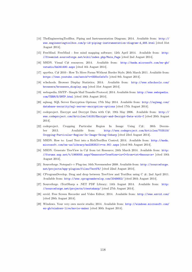
[14] TheEngineeringToolBox. Piping and Instrumentation Diagram; 2014. Available from: http://
www.engineeringtoolbox.com/p-id-piping-instrumentation-diagram-d_466.html [cited 31st
August 2014].
[15] FreeMind. FreeMind - free mind mapping software; 12th April 2014. Available from: http:
//freemind.sourceforge.net/wiki/index.php/Main_Page [cited 2nd August 2014].
[16] MSDN. Visual C# resources; 2014. Available from: http://msdn.microsoft.com/en-gb/
vstudio/hh341490.aspx [cited 4th August 2014].
[17] spyr0xx. C# 2010 - How To Move Forms Without Border Style; 26th March 2011. Available from:
https://www.youtube.com/watch?v=0XKboCsfsTc [cited 9th August 2014].
[18] w3schools. Browser Display Statistics; 2014. Available from: http://www.w3schools.com/
browsers/browsers_display.asp [cited 31st August 2014].
[19] webopedia. SMTP - Simple Mail Transfer Protocol; 2014. Available from: http://www.webopedia.
com/TERM/S/SMTP.html [cited 10th August 2014].
[20] sqlmag. SQL Server Encryption Options; 17th May 2014. Available from: http://sqlmag.com/
database-security/sql-server-encryption-options [cited 17th August 2014].
[21] codeproject. Encrypt and Decrypt Data with C#; 19th May 2006. Available from: http://
www.codeproject.com/Articles/14150/Encrypt-and-Decrypt-Data-with-C [cited 20th August
2014].
[22] codeproject. Cropping Particular Region In Image Using C#; 30th Decem-
ber 2013. Available from: http://www.codeproject.com/Articles/703519/
Cropping-Particular-Region-In-Image-Using-Csharp [cited 23rd August 2014].
[23] MSDN. How to: Load Text into a RichTextBox Control; 2014. Available from: http://msdn.
microsoft.com/en-us/library/ms228352(v=vs.90).aspx [cited 9th August 2014].
[24] MSDN. Generate TreeView in C# from txt Resource; 24th March 2014. Available from: http:
//forums.asp.net/t/1969055.aspx?Generate+TreeView+in+C+from+txt+Resource+ [cited 10th
August 2014].
[25] Sourceforge. Notepad++ Plug-ins; 16th Novemember 2008. Available from: http://sourceforge.
net/projects/npp-plugins/files/TextFX/ [cited 22nd August 2014].
[26] CProgramDevelop. Drag and drop between TreeView and TextBox using C #; 2nd April 2011.
Available from: http://www.cprogramdevelop.com/2048682/ [cited 26th August 2014].
[27] Sourceforge. iTextSharp a .NET PDF Library; 14th August 2014. Available from: http:
//sourceforge.net/projects/itextsharp/ [cited 27th August 2014].
[28] ezvid. Free Screen Recorder and Video Editor; 2014. Available from: http://www.ezvid.com/
[cited 29th August 2014].
[29] Windows. Your very own movie studio; 2014. Available from: http://windows.microsoft.com/
en-gb/windows-live/movie-maker [cited 30th August 2014].
118

Appendix A
XSLT Data Export Script
1 <?xml version="1.0"?>
2 <xsl:stylesheet version="1.0" xmlns:xsl="http://www.w3.org/1999/XSL/Transform">
3 <xsl:output method="text"/>
4 <xsl:template match="/">
5 <xsl:apply-templates/>
6 </xsl:template>
7 <xsl:template name="linebreak">
8 <xsl:text>
9 </xsl:text>
10 </xsl:template>
11 <xsl:template match="map">
12 <xsl:apply-templates select="child::node"/>
13 </xsl:template>
14 <xsl:template match="node">
15 <xsl:param name="commaCount">0</xsl:param>
16 <xsl:if test="$commaCount > 0">
17 <xsl:call-template name="writeCommas">
18 <xsl:with-param name="commaCount" select="$commaCount"/>
19 </xsl:call-template>
20 </xsl:if>
21 <xsl:value-of select="@TEXT"/>
22 <xsl:call-template name="linebreak"/>
23 <xsl:apply-templates select="child::node">
24 <xsl:with-param name="commaCount" select="$commaCount + 1"/>
25 </xsl:apply-templates></xsl:template>
26 <xsl:template name="writeCommas">
27 <xsl:param name="commaCount">0</xsl:param>
28 <xsl:if test="$commaCount > 0">-<xsl:call-template name="writeCommas">
29 <xsl:with-param name="commaCount" select="$commaCount - 1"/>
30 </xsl:call-template></xsl:if></xsl:template></xsl:stylesheet>
Listing A.1: Mind Map XSLT Script
119
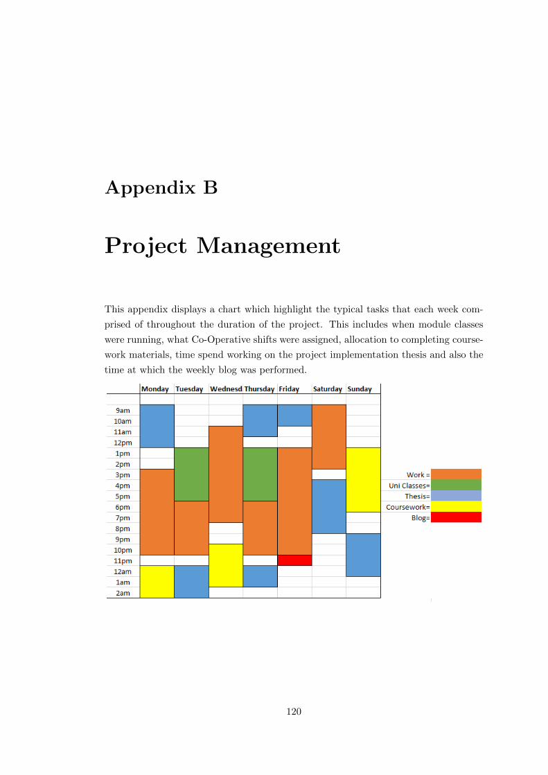
Appendix B
Project Management
This appendix displays a chart which highlight the typical tasks that each week com-
prised of throughout the duration of the project. This includes when module classes
were running, what Co-Operative shifts were assigned, allocation to completing course-
work materials, time spend working on the project implementation thesis and also the
time at which the weekly blog was performed.
120

Further project management was incorporated to identify the main deliverables of the
project showing when these major tasks were intended to be started and subsequently
completed, ensuring all the main deliverables of the project were completed in sufficient
time.
121
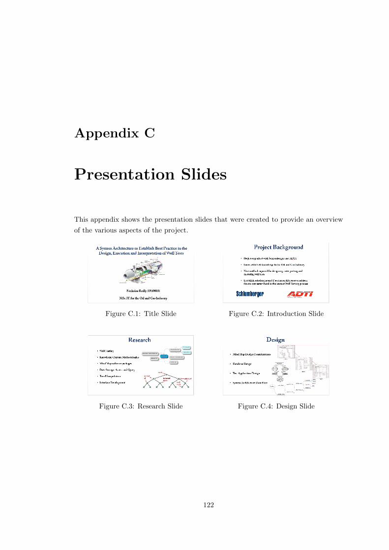
Appendix C
Presentation Slides
This appendix shows the presentation slides that were created to provide an overview
of the various aspects of the project.
Figure C.1: Title Slide Figure C.2: Introduction Slide
Figure C.3: Research Slide Figure C.4: Design Slide
122
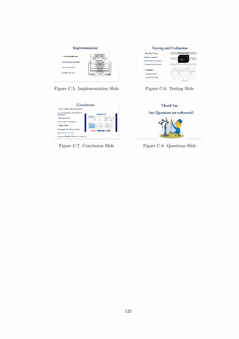
Figure C.5: Implementation Slide Figure C.6: Testing Slide
Figure C.7: Conclusion Slide Figure C.8: Questions Slide
123

Appendix D
Project Log
The following is a weekly summary of the work undertaken during the development
of this body of work. It covers tasks that were completed, tutorials that were worked
through, articles that were read and reviews of discussions / meetings held with the
project supervisor and other third parties.
Week Ending: Friday 13/06/2014
The first meeting with supervisor took place this week and involved the discussion of
our initial plans for the project implementation phase. The final project investigation
report was submitted to Tony Fitzpatrick Schlumberger for comments and feedback on
the work carried out. Contact will be initiated this week to determine how the project
implementation is to move forward. The first plan/task carried out was the creation of
some design concepts that the test application for the system architecture. A number
of design concepts will be created to broaden the potential functionality and data flow
design for the architecture and will be shown the Schlumberger to determine which
concept will be the best fit solution to progress to implement. Other tasks fulfilled this
week are as follows:
• Initial design concept drafted, more will be created
• Experimentation of tree manipulation of tabular/comma delimited text files to
refine the mind map manipulation process in the system architecture.
• Investigated creating Windows Forms login system for the application with the
use of a local database, security and encryption considered for this aspect of
implementation.
124

• Coding will commence once the design concepts have been completed to imple-
ment the test application that will be used to prove the system architecture is
effective and it achieves its goals and objectives.
• Set up project implementation latex document and entered some initial data to
structure the report.
Week Ending: Friday 20/06/2014
This week focused mainly on the implementation of the test application using the
design concepts that were created last week. This involved creating the windows form
application itself and also lots of experimenting with different data types that will be
present in the architecture. Tasks that were carried out this week are as follows:
• Created wellTESTplus C# windows forms application project to handle the data
flow in the system architecture.
• Removed custom form borer for application, this results in loss of control for the
form, due to this custom control was coded to allow the form to be closed, resized,
minimised and also moved around the screen.
• Incorporated custom graphics to stylise the form to show the invested parties in
the project and to aid in the design
• Experimented with screen resolution, maximise and restore and how components
are anchored to the form to determine when resized where the component will be
displayed.
• Downloaded and installed Microsoft SQL Server 2012 (and SQL Server Manage-
ment Studio 2012) to accommodate an external database that can communicate
with the test application and store/send data. Attempted to use SQL Workbench
to connect however could not figure out connection string.
• Successful connection with SQL Server Database and test application, due to
this a simple user login table was created in the database to store username and
password. This was used in the test application to implement a user login system
with external database verification.
• Updated latex document with weekly blog
• Plans for next week, implement a user registration system, discover best method
to manipulate exported mind map data, implement other components necessary
125
for the application to get a basic flow of data and incorporate dynamic function-
ality.
Week Ending: Friday 27/06/2014
This week continued with the implementation of more features for the test application
to adapt the functionality within the architecture. This consisted of implementing a
user registration system which is connecting to the same external MYSQL database
used for the login system. This allows the user to create an account containing details
about their first name, last name, desired username, desired password and also email
address. With successful registration the user can then login using their set details.
Another feature that was successfully implemented was sending the user confirmation
of registration through an SMTP email client, this thanks the user for registering and
provides them with verification of the username and password that they created for the
application. A strong solution for the manipulation of mind map tab separated text
files and comma delimited files was achieved and successful conversion into a TreeView
control was implemented for the first time. This provided a solution that can be used
to dynamically edit mind map data within a custom application and also that the
mind map text file can be successfully loaded into a TreeView control to allow for data
querying against an external database.
Another implementation that was successful was linking a dataGridView with an exter-
nal MYSQL table which holds data about well test tools. The table data is displayed
in the application at run time and custom functionality was added to allow the user
to add new entries to the database file in the application, save this new entry into the
external database (persistent storage) and also remove an entry from the database if
required.
LINQ queries were also tested using the MYSQL database, this consisted of a particular
TreeView node being selected then a set query will be returned in a dataGridView in the
test application. The results were positive and expected data was successfully fetched
in the application. Issues with multiple query results returns in the dataGridView, only
one per time, check boxes attached to the TreeView to allow the user to make multiple
selections-affected the query being returned or not however again only returned one
result.
Updated latex thesis document with weekly blog.
Next weeks tasks, figure out multiple tree selection and data query return. Implement
126

feature to allow the user to modify a mind map text file from the application and re-
save modifications to a new file which can then be loaded into a TreeView. Carry out
documentation on tasks up to date.
Week Ending: Friday 04/07/2014
This week focused primarily on updating the thesis report with the relevant sections
which have been carried out implementation wise. This covers the documentation of the
test application design for the system architecture, the actual design and component
interaction that the system architecture will contain and also some design aspects of
the data store/database design.
Alongside the focus on updating the design section of the thesis, parts of the implemen-
tation section of the document have been started, this is where the system architecture
is being developed and discussions about issues that arose and the solutions to these
problems were derived. This includes, creating the C# application in Microsoft Vi-
sual Studio, the use and implementation of the mind map software, with regard to the
architecture, and an initial chain of data flow and the components to achieve these.
Further research was undertaken to find a solution for the multiple query return into
single dataGridView, no such solution has yet been derived, possible is the use of a
String Builder, this may allow the concatenation of multiple queries.
The plan for next week is to continue writing up all findings in the thesis report and
to continue sharpening features that are currently implemented and to pursue to find
solutions to the components that are not yet successfully implemented.
Week Ending: Friday 11/07/2014
This week was primarily spent revising for the mock assessed lab for the Intranet
Systems Development module however the updating of the design section of the thesis
document was carried out. This covered some of the initial design considerations that
were made for the system architecture such as:
• The construction of the external mind map program, Freemind and XMind
• The extraction of mind map data and how this will be used in the C# test
application
127

• The exportation of the original mind map file and data types, advantages and
disadvantages of these formats and how they can be used in the test application
• Initial database design considerations were documented, ER and relation table
models still to be created to identify the data types that will be required for the
DB to handle.
Alongside these tasks, initial design concept sketches of the C# test application were
created to establish how the application will look and to cover the various internal
components that will be necessary in this application to ensure it can handle the data
passing from the architecure.
Next week’s task is to continue updating the thesis document design section with any
remaining sections and pad out some of the sections that have already been started.
Due to the actual implementation of the application being well under-way, the decision
made for this week and next is to catch up with the documentation side of things and
make this the primary focus before commencing further coding.
Week Ending: Friday 18/07/2014
This week consisted predominantly of thesis report writing, which involved completing
the majority of the design chapter which included sections such as:
• Finished documenting the initial design concept sketches to ensure they are fully
described
• Created digital versions of the concept design sketches
• Documented the digital concepts to further elaborate on the design considerations
made for the test application
The issue with loading the tab separated text file was finally solved, using Notepad++,
as hidden characters can be shown, and it was identified that although the text file
appeared to be in perfect tab separated form, it was actually four blank characters
for every apparent tab present. A plug-in was downloaded to convert these blank
spaces into tab form and from this the text file can now be successfully loaded into the
tree control, provided evidence that the algorithm used was valid, it was merely the
construction of the text file that was limiting the functionality.
Other essential non-university related commitments resulted in a diluted focus on re-
sulting in not as much focus on the project, following week back to normal so more
focus will be applied to the project.
128

Tasks for next week include documenting the implementation tasks that have already
been carried out, addressing what was done and the problems that were encountered.
Testing of these sections will be carried out at the same time to pad out the thesis
document and to provide evidence that testing was applied during the implementation
of these components. Next week will also look at implementing the document builder
components and further research will be undertaken to identify the issue of multiple
database queries being returned in a single query window.
Week Ending: Friday 25/07/2014
This week consisted of continuing with updating the thesis document covering the stages
of implementation that have been undertaken. This details the initial development of
the C# windows form components and covers the algorithms/code that was used to
achieve this.
Alongside this, developmental testing was also carried out and documented to show
that the program is achieving its desired outcomes for its purpose.
Next week contact with Schlumberger will be made to arrange a meeting to acquire
the needed data as the architecture is almost complete, just needs proper data now to
validate that it will be effective for its task and will provide accurate results related to
well test conditions and parameters.
The final section remaining of the test program is the pdf creator and viewer. Tutorials
have been viewed to establish how to achieve this and the initial stages of implemen-
tation were carried out to test if it was viable with the data types featured in the test
program.
Tasks for next week are to complete the pdf creator/viewer so it is ready to take in the
different data types featured throughout the test program, continue documenting the
implementation aspect of the project and also testing of these components.
Week Ending: Friday 01/08/2014
This week saw major progress in the implementation of test application for the system
architecture.
New method for processing tree items was implemented utilising drag and drop to text
boxes to allow relevant information to be processed against the database of well test
129

tools.
Alongside this a solution was created to display multiple database query returns based
on tree selections and was incorporated into a scrollable panel displaying each query in a
datagridview inside this panel, before only one datagridview query would be displayed.
Another feature that was implemented was the Adobe PDF reader, this allows for
PDF documents to be read within the test application, reducing the need for third
party external document viewing software.
To accommodate this, a method was also implemented to allow the user to create a
PDF document containing all the important information that is present or entered in
the test application about that particular well test. This uses a .dll extension for c#
called iTextSharp, this encapsulated all the data correctly however increased styling is
to be tested to make the document look more official.
Tweaks were made to the application to improve the usability and general functionality
of the test application.
Another feature which was implemented was the ability for the user to take a screen-
shot of the mind map Flash Applet, this proved unsuccessful as the method couldn’t
isolate the Flash applet, instead took an offset picture of the form. Due to this a method
was implemented to take a screen-shot of the entire form in high quality. In order to
take a picture of the mind map flash applet(to be used as image in PDF) a custom
cropping tool was created to allow the user to load the screen-shot of the form, and
by clicking four points around the relevant area of the image, this would be cropped in
high detail and can be saved to then be used in the PDF document.
Alongside the development of the test application the remaining sections of the de-
sign chapter in the thesis document were completed, which included the database table
designs for Login and Tool List tables. Additionally, DFD’s were created for the admin-
istrator and user role’s for the system architecture to encapsulate all the anticipated
flow of data throughout the system architecture.
Tasks for next week- continue documenting implementation/testing chapters of the the-
sis document, meet with engineers to obtain proper data to begin testing and validating
the test application to prove it provides accurate results. This will require algorithm
tweaking. Adapt PDF document creator to contain better styling.
130

Week Ending: Friday 08/08/2014
This week saw progression in the implementation and testing sections of the thesis
document, this will be the major focus for the next few weeks to complete the docu-
mentation to a high standard and encapsulate all the development carried out and the
problems that arose and how they were solved.
Alongside this, user-name retrieval and password reset was also implemented and tested
to ensure that it would work properly. There were initial issues with it changing the
password for an irrelevant address, or unspecified address so this was solved to ensure
that it would only change the password if the email address had been verified to exist.
Extra tweaks were made to the application to ensure that all aspects of functionality
have been addressed.
Word still not received from Schlumberger, however will be arranging a meeting with
ADTi engineers to acquire some well test data that will be entered into the application
to prove that it is fit for purpose.
This week largely spent focusing on revising for the upcoming Intranet Systems De-
velopment assessed lab next Monday, with an exam the following Monday after that.
Documentation and development will continue during this however as time does need
to be allocated to these exams.
After exams are completed the entire focus will be on finishing every aspect of the
project to ensure the deadline is met. Task for next week- get some real data for the
application, brush up the adobe creator document and continue documentation.
Week Ending: Friday 15/08/2014
This week again focused predominantly on revision for the Intranet Systems Develop-
ment module as this is the last exam that will be undertaken before completion of the
course. Despite this being the main focus of studying, some tasks were carried out
relating to the project implementation to ensure some project activity was performed.
The tasks that were carried out this week are as follows:
Implementation chapter of the thesis document was updated. This will still be the main
focus for the coming weeks along with the testing and evaluation chapter. Relevant
sections have been mapped out so the structure of the report is incorporated.
131

Data encryption and decryption was investigated to determine a best method for en-
suring sensitive data such as usernames and passwords are protected when using the
application. The method found most effective for this task was Hashing. A test ap-
plication was created to experiment using this and the results indicated that this was
effective. This will be used in the system architecture to protect data.
Tasks for next week include updating the thesis document as much as possible which
will be the main focus. Implement the data encryption and decryption into the test
application. Add a help form to each tab in the test application to highlight to the user
how to best use the system, this may include the development of a wellTEST+ user
manual. Meet with ADTi engineers to acquire some proper data which will be plugged
into the application to try and achieve effective results. These are the final aspects of
the project implementation that are required before the system architecture is complete,
and all that will remain will be extra tweaks and to complete documentation.
Week Ending: Friday 22/08/2014
This week concluded exams for the remaining module of this semester. Due to this the
first half of the project week was spent revising for that to ensure the last exam went
as well as possible. Tasks that were carried out this week despite busy schedule are as
follows:
Username encryption and decryption were implemented into the test application for
the architecture, this makes username retrieval much more secure, investigation into
best method for resetting password is being looked at, hopefully a new secure method
can be incorporated to result in secure user details throughout the application.
Another task that was completed was refining the GUI to ensure that each relevant
task was clearly identified as to invoke no ambiguity in the steps the user will need
to take. Alongside this a help feature was implemented to show the user how to use
the application if there is any uncertainties. This takes the form of a video tutorial
built into the application which covers each step, also contains a user manual document
which can be referenced, it also details what is featured in the video.
Arranged meeting with ADTi engineers at the beginning of next week to acquire some
relevant data, which will be the simplest string of information to ensure that it can
be implemented successfully within the given timeframe of the project. Expanding the
data would be a future development consideration.
132

Focus for next week, acquire data, polish up GUI and continue with the thesis docu-
ment; this is the primary focus for the next two weeks.
Week Ending: Friday 29/08/2014
This week was the last full week before the conclusion of the project implementation.
Due to this all focus was on completing the documentation to ensure that it will be
submit by the deliverable date. Meeting with ADTi engineers will take place at the
weekend to acquire some sample data to use in the application. Alongside this, final
tweaks will be made to the application to ensure it is as professional as possible before
the submission.
Tasks for next week are to continue completing the report and any necessary changes to
what has already been implemented. Preparation will also be made for the presentation
and demonstration which is taking place on Thuursday 4th September shortly after the
report is submitted.
This concludes the weekly blog for the project.
133