Embed Size (px)
Citation preview
0
Final Report
Hybrid Synth by Synthesize Me
Members: Jamie Madaris Jack Nanney
Project Abstract
Our Senior Design project is a Digitally-Controlled Analog Synthesizer. The synthesizer consists of both digital and analog parts. The digital section is the control system for the analog section. The digital control accepts MIDI input, and outputs a control voltage for the oscillators, as well as two low frequency oscillators (LFO) to modulate the analog signal. The analog segment is the synthesizer system. It consists of three voltage controlled oscillators(VCO), a signal mixer, a voltage controlled filter (VCF) with an envelope generator, and a voltage controlled amplifier (VCA) with an envelope generator. Each of these modules can be modulated by the LFOs.
1
Table of Contents Project Features 2 Technical Objectives 2 Analysis of Competitive Products 2 Concept/ Technology Background 3 Project Architecture 6 User Manual 7 Division of Labor 8 Bill of Materials 8 Gantt Chart 9 Appendix 10
List of Tables and Figures Xboard49 Picture 2 Triangle wave Fourier series (Source: http://en.wikipedia.org/wiki/Triangle_wave) 3 Square wave Fourier Series (Source: http://en.wikipedia.org/wiki/Square_wave) 3 Sawtooth wave Fourier Series (Source: http://en.wikipedia.org/wiki/Sawtooth_wave) 4 ADSR Envelope (Source:
http://ems.music.uiuc.edu/beaucham/software/ m4c/m4c_intro_html/M4C_intro.ADSR.png) 5 Project Block Diagram 6 Front Panel Diagram 7 Division of Labor 8 Bill of Materials 8 Gantt Chart 9 Software Chart for Microprocessor #1 10 Software Chart for Microprocessor #2 - #3 11 CV/GV/LFO/Glide Circuit Schematic 12 CV/GV/LFO/Glide Printed Circuit Board 13 Voltage Controlled Oscillator Circuit Schematic 14 Voltage Controlled Oscillator Printed Circuit Board 15 Voltage Controlled Filter Circuit Schematic 16 Voltage Controlled Filter Printed Circuit Board 17 Voltage Controlled Amplifier Circuit Schematic 18 Voltage Controlled Amplifier Printed Circuit Board 19
2
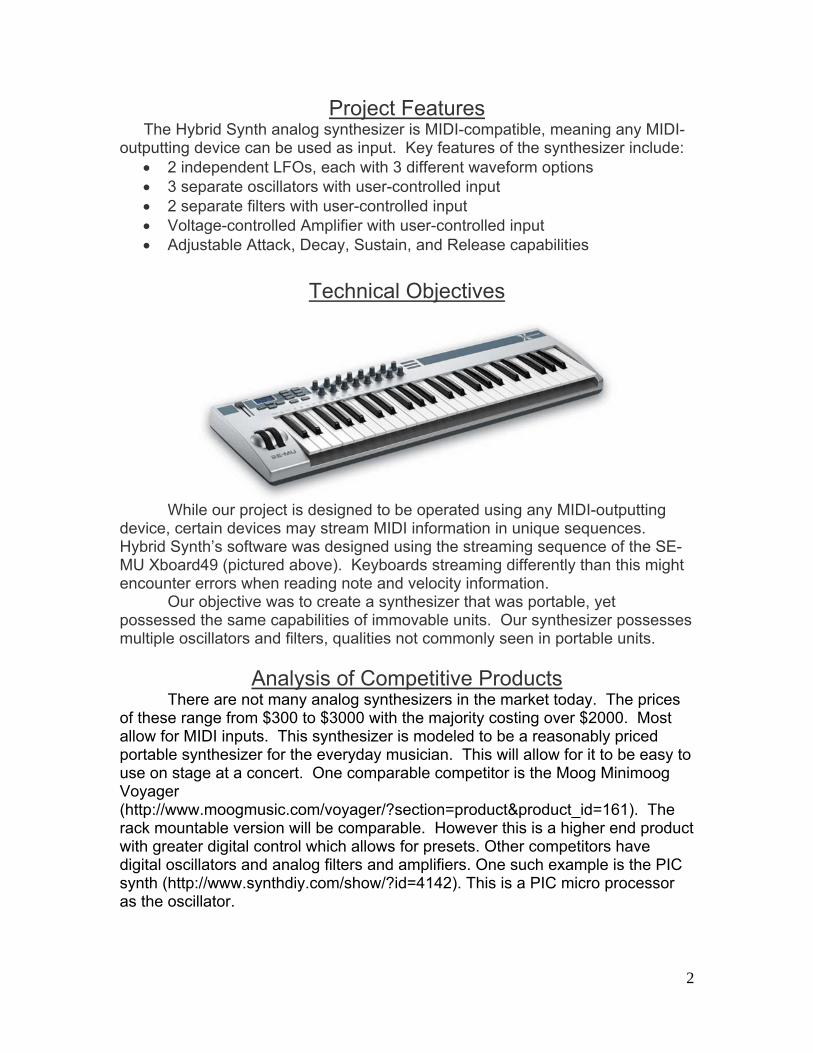
Project Features The Hybrid Synth analog synthesizer is MIDI-compatible, meaning any MIDI-
outputting device can be used as input. Key features of the synthesizer include: 2 independent LFOs, each with 3 different waveform options 3 separate oscillators with user-controlled input 2 separate filters with user-controlled input Voltage-controlled Amplifier with user-controlled input Adjustable Attack, Decay, Sustain, and Release capabilities
Technical Objectives
While our project is designed to be operated using any MIDI-outputting device, certain devices may stream MIDI information in unique sequences. Hybrid Synth’s software was designed using the streaming sequence of the SE-MU Xboard49 (pictured above). Keyboards streaming differently than this might encounter errors when reading note and velocity information. Our objective was to create a synthesizer that was portable, yet possessed the same capabilities of immovable units. Our synthesizer possesses multiple oscillators and filters, qualities not commonly seen in portable units.
Analysis of Competitive Products There are not many analog synthesizers in the market today. The prices
of these range from $300 to $3000 with the majority costing over $2000. Most allow for MIDI inputs. This synthesizer is modeled to be a reasonably priced portable synthesizer for the everyday musician. This will allow for it to be easy to use on stage at a concert. One comparable competitor is the Moog Minimoog Voyager (http://www.moogmusic.com/voyager/?section=product&product_id=161). The rack mountable version will be comparable. However this is a higher end product with greater digital control which allows for presets. Other competitors have digital oscillators and analog filters and amplifiers. One such example is the PIC synth (http://www.synthdiy.com/show/?id=4142). This is a PIC micro processor as the oscillator.
3
Concept/ Technology Background
There are several different methods for audio synthesis. The most popular
methods are additive synthesis, subtractive synthesis, and modeling synthesis. Additive synthesis creates its sounds by adding together weighted harmonics to produce a waveform. This is essentially the Fourier series. Subtractive synthesis involves beginning with a harmonically rich source and apply filters to remove and dampen the harmonics to create the sound desired. Modeling synthesis uses mathematical formulas to emulate sounds of instruments. This is usually implemented with DSP processors.
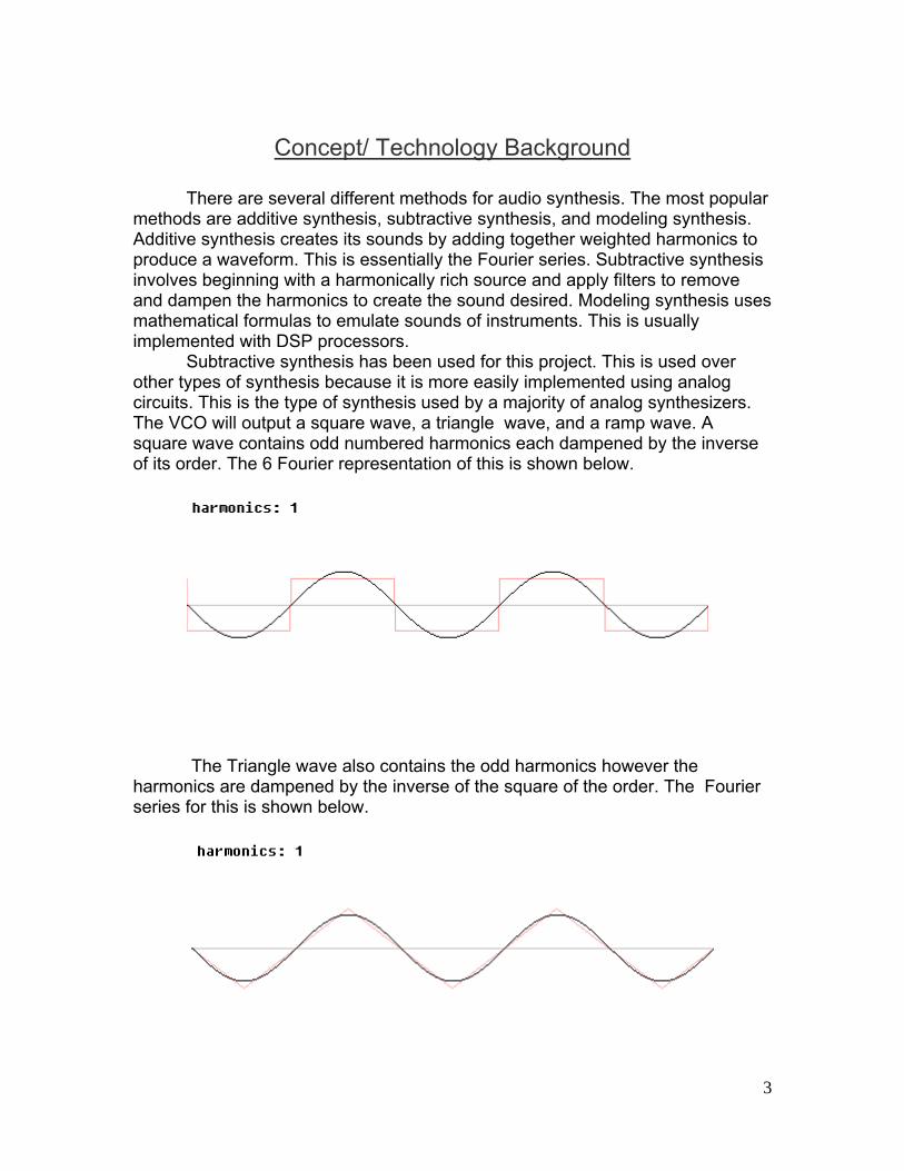
Subtractive synthesis has been used for this project. This is used over other types of synthesis because it is more easily implemented using analog circuits. This is the type of synthesis used by a majority of analog synthesizers. The VCO will output a square wave, a triangle wave, and a ramp wave. A square wave contains odd numbered harmonics each dampened by the inverse of its order. The 6 Fourier representation of this is shown below.
The Triangle wave also contains the odd harmonics however the harmonics are dampened by the inverse of the square of the order. The Fourier series for this is shown below.
4
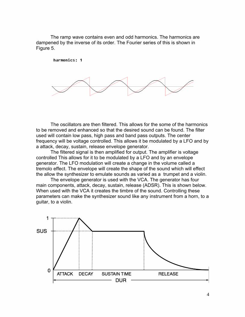
The ramp wave contains even and odd harmonics. The harmonics are
dampened by the inverse of its order. The Fourier series of this is shown in Figure 5.
The oscillators are then filtered. This allows for the some of the harmonics
to be removed and enhanced so that the desired sound can be found. The filter used will contain low pass, high pass and band pass outputs. The center frequency will be voltage controlled. This allows it be modulated by a LFO and by a attack, decay, sustain, release envelope generator.
The filtered signal is then amplified for output. The amplifier is voltage controlled This allows for it to be modulated by a LFO and by an envelope generator. The LFO modulation will create a change in the volume called a tremolo effect. The envelope will create the shape of the sound which will effect the allow the synthesizer to emulate sounds as varied as a trumpet and a violin.
The envelope generator is used with the VCA. The generator has four main components, attack, decay, sustain, release (ADSR). This is shown below. When used with the VCA it creates the timbre of the sound. Controlling these parameters can make the synthesizer sound like any instrument from a horn, to a guitar, to a violin.
5
The analog modules will be controlled digitally. The controller will have a
MIDI input. This will allow for a large variety of MIDI devices to be used; a MIDI keyboard will be used in this case. The controller will output a control voltage. This will be sent to the oscillators to control the frequency of oscillation. It will also out put a gate voltage. This is used to initiate the start of the envelope generator. The controller will also output a low frequency oscillator with sine, triangle and square waves.
6
Project Architecture
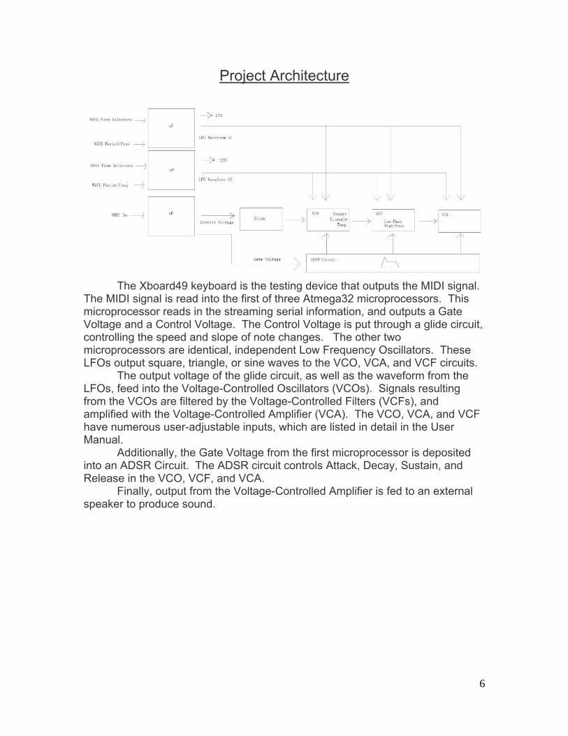
The Xboard49 keyboard is the testing device that outputs the MIDI signal.
The MIDI signal is read into the first of three Atmega32 microprocessors. This microprocessor reads in the streaming serial information, and outputs a Gate Voltage and a Control Voltage. The Control Voltage is put through a glide circuit, controlling the speed and slope of note changes. The other two microprocessors are identical, independent Low Frequency Oscillators. These LFOs output square, triangle, or sine waves to the VCO, VCA, and VCF circuits.
The output voltage of the glide circuit, as well as the waveform from the LFOs, feed into the Voltage-Controlled Oscillators (VCOs). Signals resulting from the VCOs are filtered by the Voltage-Controlled Filters (VCFs), and amplified with the Voltage-Controlled Amplifier (VCA). The VCO, VCA, and VCF have numerous user-adjustable inputs, which are listed in detail in the User Manual.
Additionally, the Gate Voltage from the first microprocessor is deposited into an ADSR Circuit. The ADSR circuit controls Attack, Decay, Sustain, and Release in the VCO, VCF, and VCA.
Finally, output from the Voltage-Controlled Amplifier is fed to an external speaker to produce sound.
7
User Manual
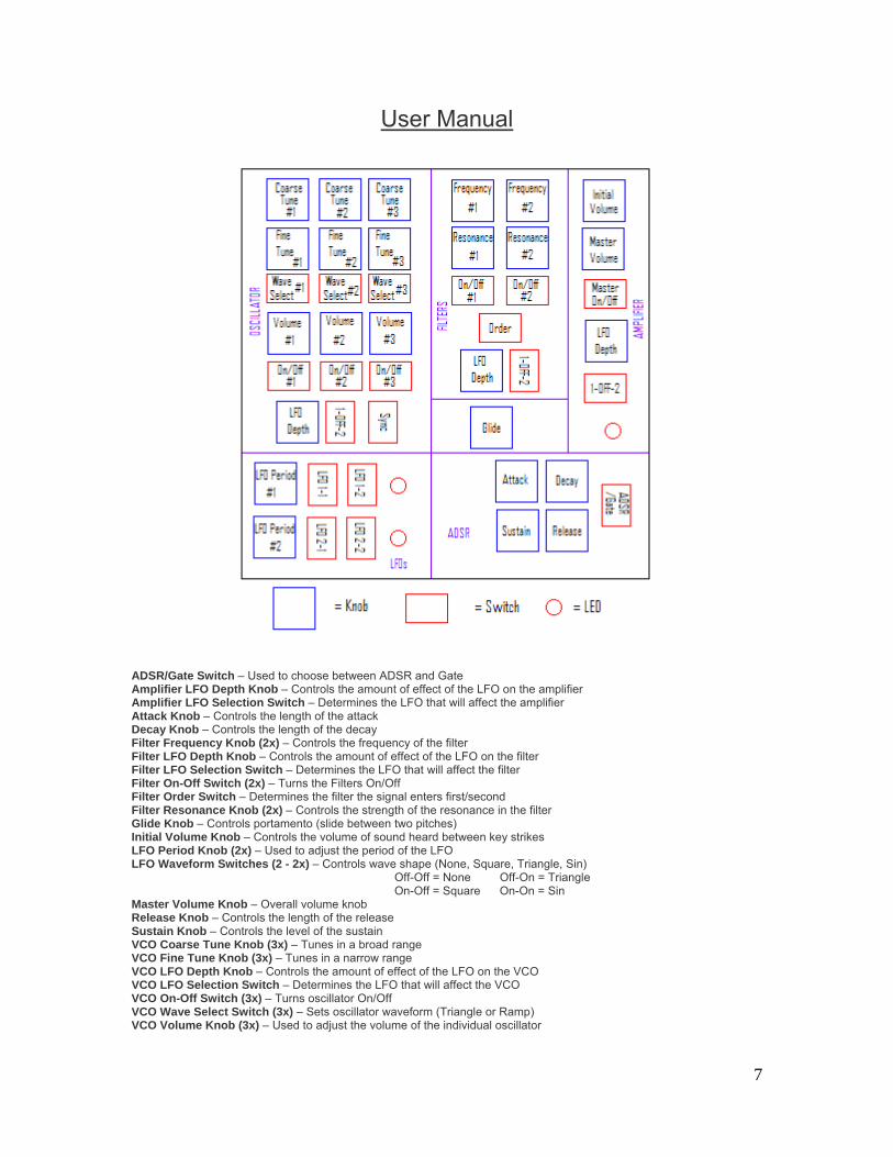
ADSR/Gate Switch – Used to choose between ADSR and Gate Amplifier LFO Depth Knob – Controls the amount of effect of the LFO on the amplifier Amplifier LFO Selection Switch – Determines the LFO that will affect the amplifier Attack Knob – Controls the length of the attack Decay Knob – Controls the length of the decay Filter Frequency Knob (2x) – Controls the frequency of the filter Filter LFO Depth Knob – Controls the amount of effect of the LFO on the filter Filter LFO Selection Switch – Determines the LFO that will affect the filter Filter On-Off Switch (2x) – Turns the Filters On/Off Filter Order Switch – Determines the filter the signal enters first/second Filter Resonance Knob (2x) – Controls the strength of the resonance in the filter Glide Knob – Controls portamento (slide between two pitches) Initial Volume Knob – Controls the volume of sound heard between key strikes LFO Period Knob (2x) – Used to adjust the period of the LFO LFO Waveform Switches (2 - 2x) – Controls wave shape (None, Square, Triangle, Sin) Off-Off = None Off-On = Triangle On-Off = Square On-On = Sin Master Volume Knob – Overall volume knob Release Knob – Controls the length of the release Sustain Knob – Controls the level of the sustain VCO Coarse Tune Knob (3x) – Tunes in a broad range VCO Fine Tune Knob (3x) – Tunes in a narrow range VCO LFO Depth Knob – Controls the amount of effect of the LFO on the VCO VCO LFO Selection Switch – Determines the LFO that will affect the VCO VCO On-Off Switch (3x) – Turns oscillator On/Off VCO Wave Select Switch (3x) – Sets oscillator waveform (Triangle or Ramp) VCO Volume Knob (3x) – Used to adjust the volume of the individual oscillator
8
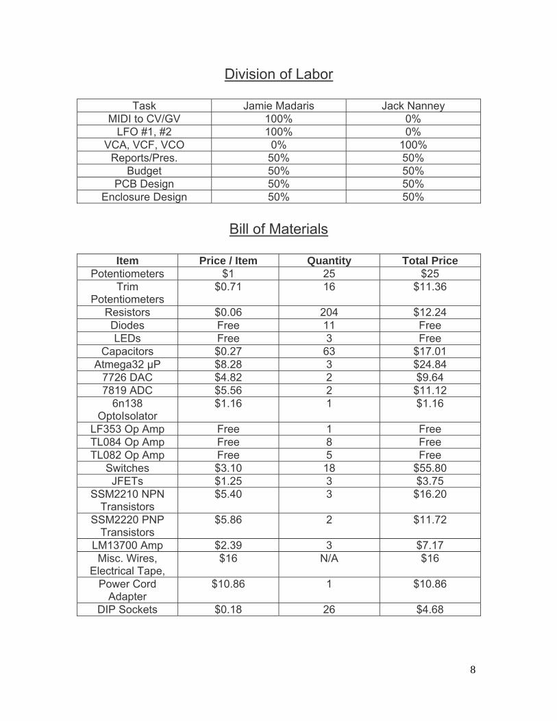
Division of Labor
Task Jamie Madaris Jack Nanney MIDI to CV/GV 100% 0%
LFO #1, #2 100% 0% VCA, VCF, VCO 0% 100%
Reports/Pres. 50% 50% Budget 50% 50%
PCB Design 50% 50% Enclosure Design 50% 50%
Bill of Materials
Item Price / Item Quantity Total Price
Potentiometers $1 25 $25 Trim
Potentiometers $0.71 16 $11.36
Resistors $0.06 204 $12.24 Diodes Free 11 Free LEDs Free 3 Free
Capacitors $0.27 63 $17.01 Atmega32 μP $8.28 3 $24.84
7726 DAC $4.82 2 $9.64 7819 ADC $5.56 2 $11.12
6n138 OptoIsolator
$1.16 1 $1.16
LF353 Op Amp Free 1 Free TL084 Op Amp Free 8 Free TL082 Op Amp Free 5 Free
Switches $3.10 18 $55.80 JFETs $1.25 3 $3.75
SSM2210 NPN Transistors
$5.40 3 $16.20
SSM2220 PNP Transistors
$5.86 2 $11.72
LM13700 Amp $2.39 3 $7.17 Misc. Wires,
Electrical Tape, $16 N/A $16
Power Cord Adapter
$10.86 1 $10.86
DIP Sockets $0.18 26 $4.68

9
Gantt Chart
10
Appendix
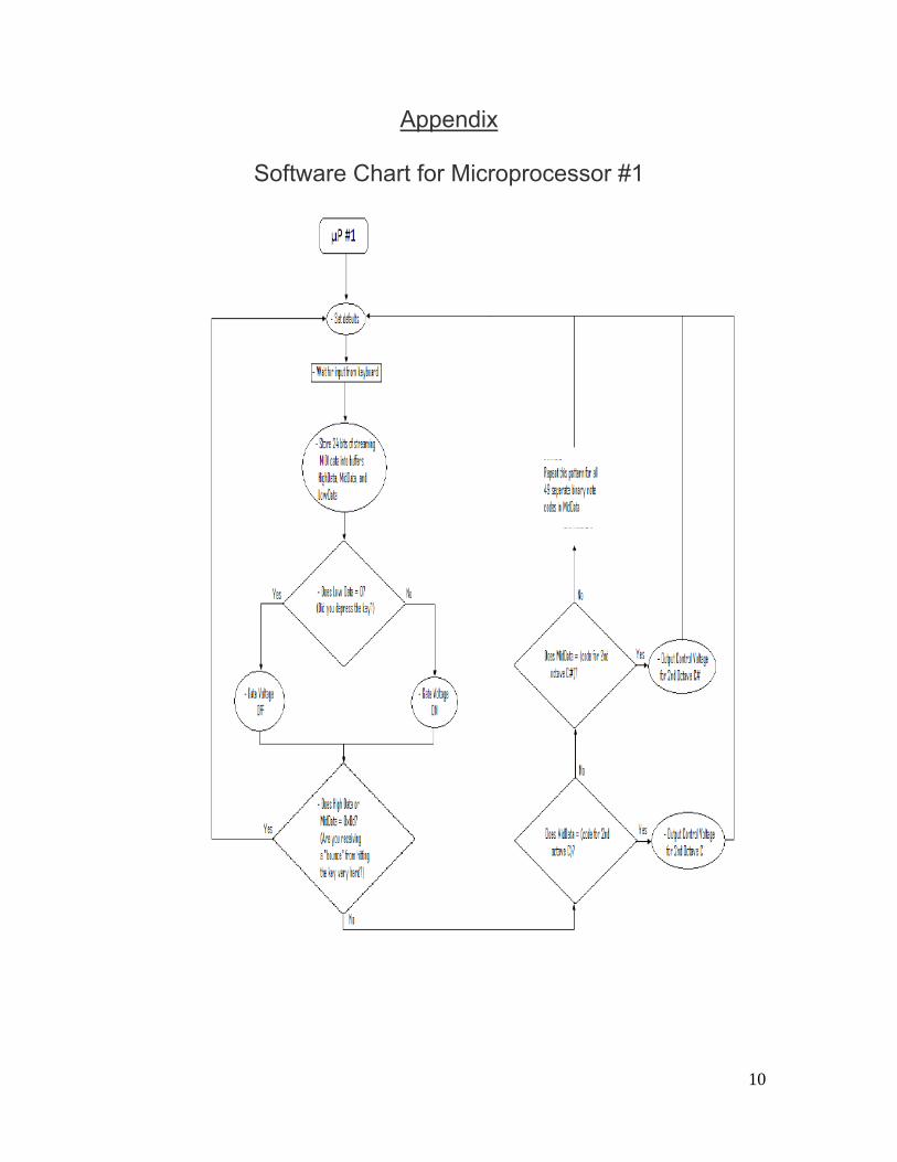
Software Chart for Microprocessor #1
11
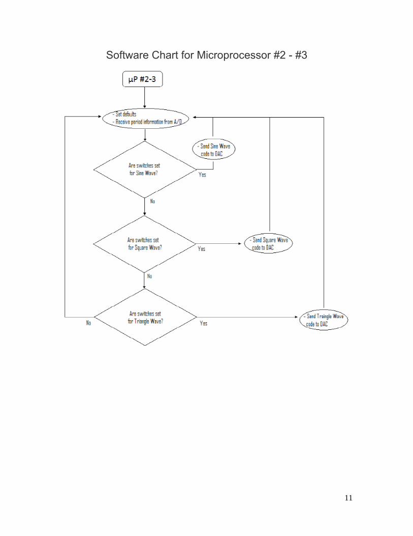
Software Chart for Microprocessor #2 - #3
12
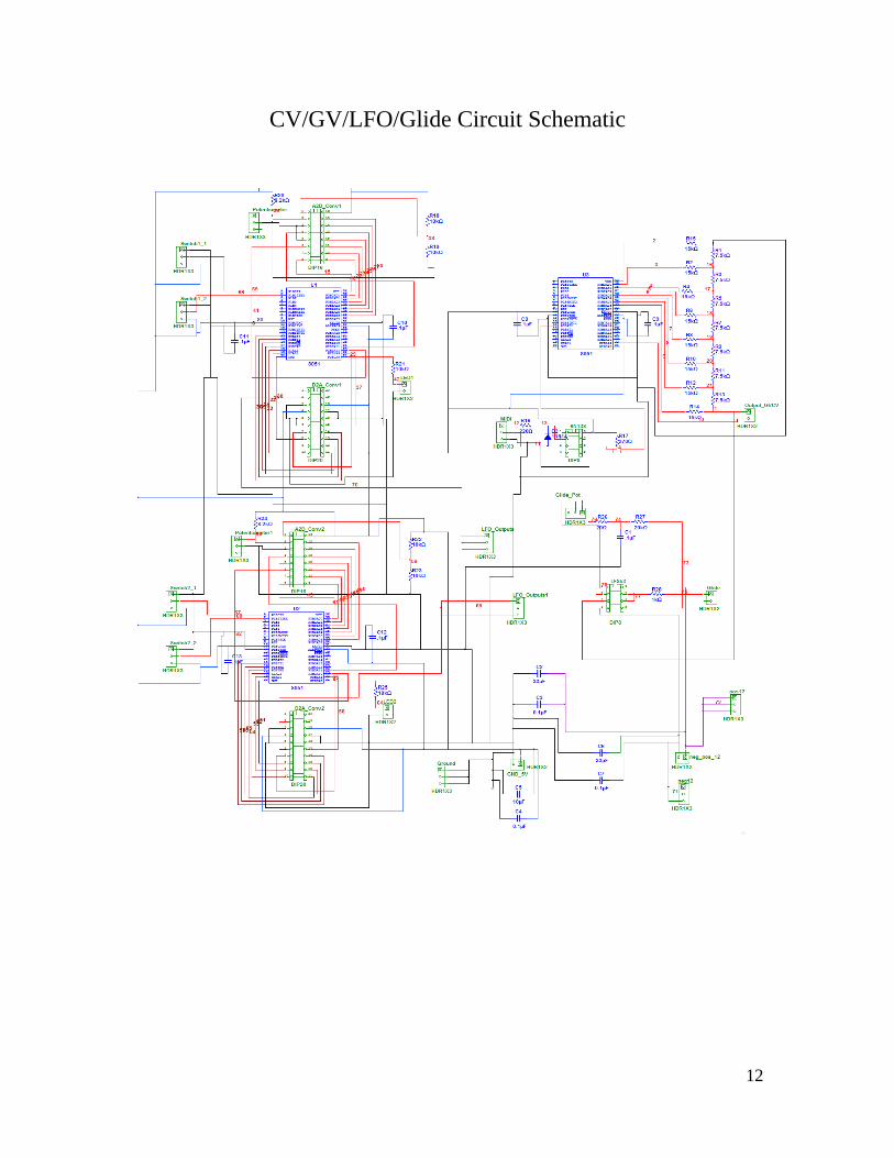
CV/GV/LFO/Glide Circuit Schematic

13
CV/GV/LFO/Glide Circuit Printed Circuit Board

14
Voltage Controlled Oscillator Circuit Schematic
15
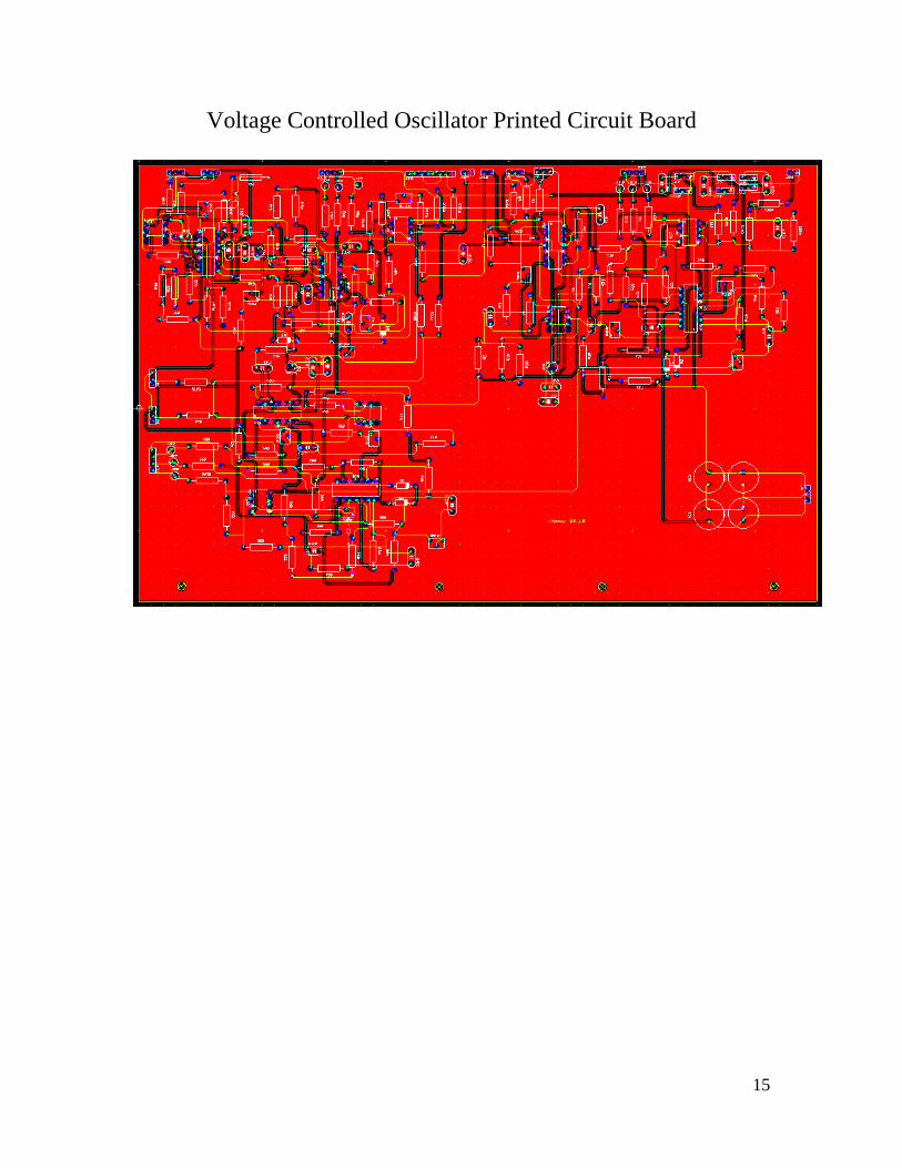
Voltage Controlled Oscillator Printed Circuit Board

16
Voltage Controlled Filter Circuit Schematic

17
Voltage Controlled Filter Printed Circuit Board

18
Voltage Controlled Amplifier Circuit Schematic
19
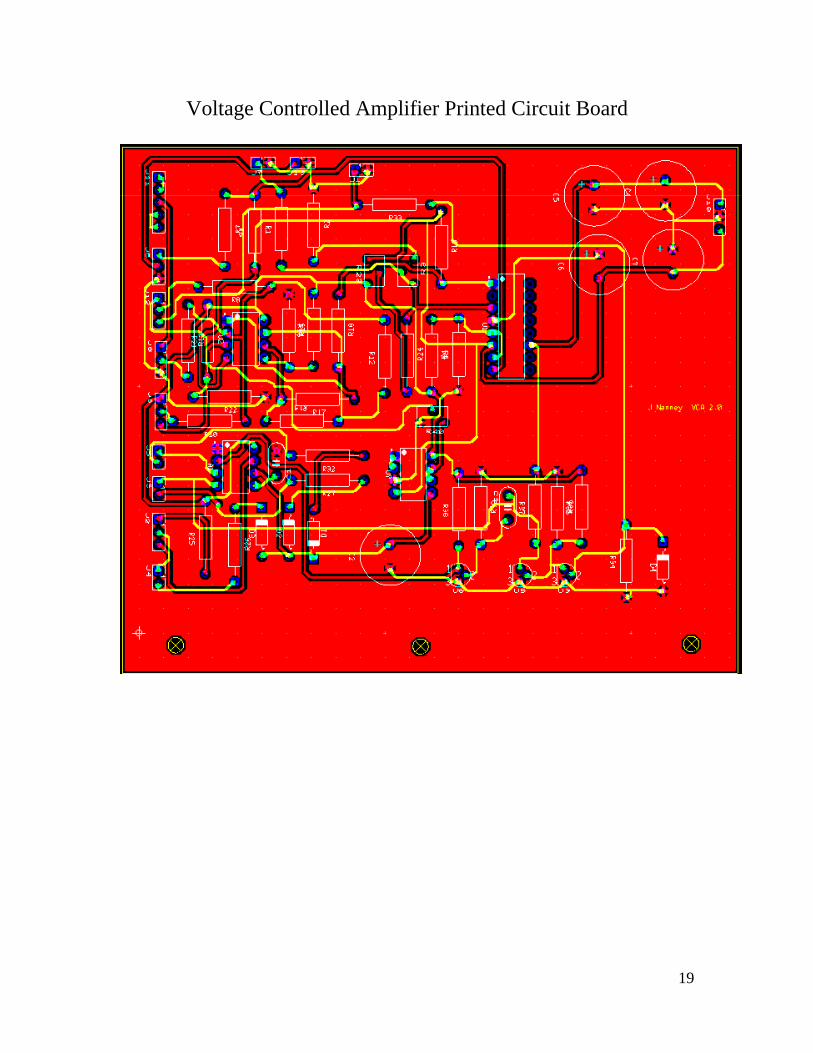
Voltage Controlled Amplifier Printed Circuit Board


![Published By: HIVE [karachi]€¦ · Ahl-e-Hadith Wafaq al -Madaris al-Salafiya Shia Wafaq al -Madaris al-Shia ... (JUI-F) and Maulana Samiul Haq (JUI-S) run more than 65 per cent](https://img.pdfslide.us/doc/110x75/610bf96e97f2096f8260b027/published-by-hive-karachi-ahl-e-hadith-wafaq-al-madaris-al-salafiya-shia-wafaq.jpg)