Embed Size (px)
Citation preview

Training in Al-Ain Distribution Company
AADC
Final Report Submitted for Partial Fulfillment of the
B.Sc. Degree in Electrical Engineering
By
Hamad Mohammed Ali ALSaadi 201010114
Submission Date: 4/1/2015
Fall 2014-2015

I
Acknowledgments
In the beginning of my reports I want to say thanks for every person help me to reach
to the training course or for the people who have contributed to making me qualify to
take training course starting by my training advisor Dr. Mousa hussain for leading us
during 16 weeks of training, guide us and even visit us in the company and ask us if
we faced any problem during my training. Also, I appreciate the efforts of all the
members of ALAin Distribution Company for giving us from their time and sharing
with us their experience not only during the training course but their door are always
open for the students. Special thanks go to Training and Graduation Projects Unit in
UAE University head by Dr. Sameera and her team (Dr. Mustafa extra…..). Thanks
from the depths to Hessa I will never forget her rule for being with us from one whole
year not one course and follow us from the starting point to complete requested paper.
Finally thanks for Members of the University who gave me the confidence to
represent the university in one of the most important companies in the UAE.

II
Executive Summary:
The training course was 16 weeks its start in 7 of September and finish in 25 of
December. In these 16 weeks I moved among two basis directorates and one division.
Project Delivery Division: four weeks were spent in this division from 7/9/2014 to
30/9/2014. They are responsible about executing Power & Water projects and follow
with the contractor step by step until closing of the project.
Asset directorate: the next four week in my training course were sent in the Asset
directorate which was from 6/10/2014 to 30/10/2014. It is include three departments
and these departments focus on the company's asset, planning for coming years,
updating all the new developments in the system and record it in the company's
archive.
Electricity operation and maintains directorate: I spent the last 8 weeks in this
directorate which from 2/11/2014 to 25/12/2014. They are responsible about the
maintenance of all equipments in the ALAin network until equipments need to be
replaced so they distribute maintenance on the different departments:
Operation and Maintenance Department: I spent three weeks in this department from
2/11/2014 to 20/11/2014 which include 4 sections. Cable sections for cables
maintenance and specify the fault location. OHL section is responsible for the
maintenance of all the equipments that related to the OHL pole, insulators and
switches. Substation maintenance section is responsible about maintenance of most of
the equipments in the substations such as transformers and CB. Operation section is
responsible about isolate the fault for previous sections and restores the supply to the
customers at the end.
Field service department include two sections street lighting section and VIP section.
This department serve a governmental property starting from palaces, hospitals extra..
I spent two weeks in this department.
Network management division: Two weeks were spent in this division, it is
responsible to monitor the power network and control it remotely

III
List of Tables and Charts
Table Or Chart Description Page
Chart 1.1 AADC Organizational chart 2
Chart 2.1.1 Project life Cycle 4
Chart 2.2.1 Asset organizational structure 12
Chart 2.3.1 EOMD organizational structure 16
Table 2.3.1 Type of the Cables 20
Chart 2.3.2 NMD organizational structure 29
List of Figures
Figure Description Page
Figure 2.1.1 Standard of any project 5
Figure 2.1.2 New development 5
Figure 2.1.3 Grid station,33KVswitch gear 7
Figure 2.1.4 Brick built & Its structure 7
Figure 2.1.5 Package Unit & its structure 7
Figure 2.1.6 GMT with FP 8
Figure 2.1.7 Check the Coordination 8
Figure 2.1.8 Distance between 11KV cables 9
Figure 2.1.9 Cement Pieces to protect cable 9
Figure 2.1.10 Warning plastic tap 9
Figure 2.1.11 Warning fixed cement piece 9
Figure 2.1.12 Water Pipe 10
Figure 2.2.1 Serial number of TR 14
Figure 2.2.2 Material in the Store 15
Figure 2.3.1 GIS System 17
Figure 2.3.2 SFT request 17
Figure 2.3.3 Burn process 17
Figure 2.3.4 TDR Screen 18
Figure 2.3.5 Person with dig headphone 18
Figure 2.3.6 Fault of the cable 18
Figure 2.3.7 More than one cable in trench 18
Figure 2.3.8 Sender device 19
Figure 2.3.9 Receiver device 19
IV
List of Figures (2)
Figure 2.3.10 Locator device 20
Figure 2.3.11 Spick gun 20
Figure 2.3.12 Cable Component 20
Figure 2.3.13 warning signs 23
Figure 2.3.14 Lock 23
Figure 2.3.15 Filling the Transformer 25
Figure 2.3.16 Fill CB 25
Figure 2.3.17 Control Cabinet 27
Figure 2.3.18 1000 W light 27
Figure 2.3.19 Diesel Generator 27
Figure 2.3.20 RTU 30
Figure 2.3.21 Fiber Optic Cable 30
Figure 2.3.22 Control center screen 32
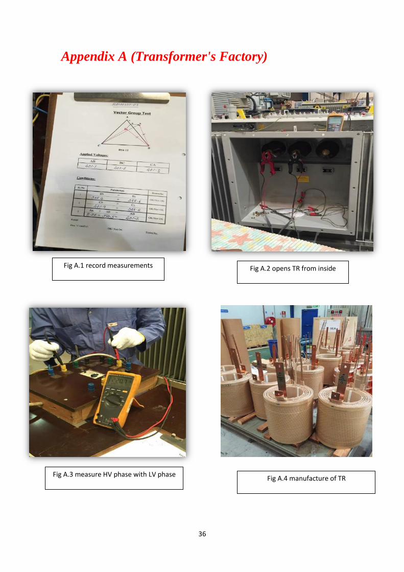
Figure A.1 Record measurements 36
Figure A.2 Opens TR from inside 36
Figure A.3 Measure HV phase with LV phase 36
Figure A.4 Manufacture of TR 36
Figure B.1 PMT 37
Figure B.2 Pin insulator 37
Figure B.3 Master Head Switch 37
Figure B.4 Auto-recloser 37
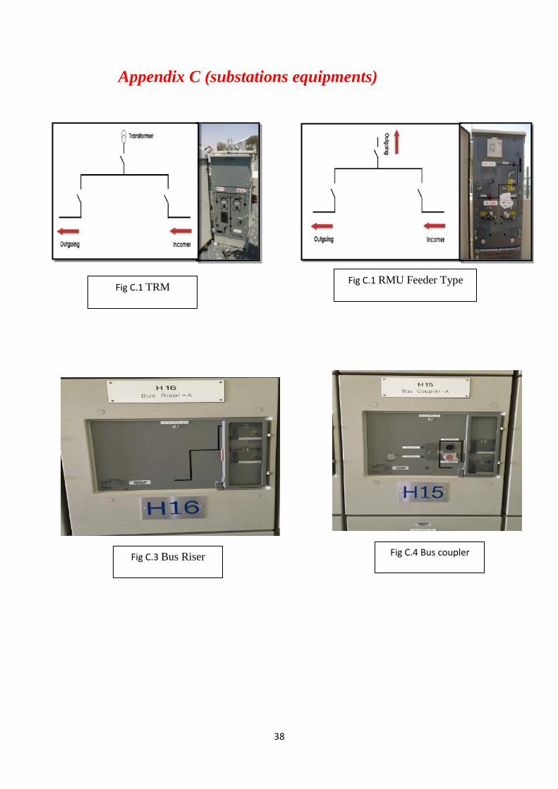
Figure C.1 TRM 38
Figure C.2 RMU Feeder Type 38
Figure C.3 Drawing of Bus Riser 38
Figure C.4 Drawing of Bus Coupler 38

V
Nomenclature
AADC Al-Ain Distribution Company CB Circuit Breaker
HV High Voltage 33 KV TDR Time Domain Reflect meter
LV Low Voltage 415 V RTU Remote Terminal Unit
OHL Over Head Line SCADA Supervisory Control And Data Acquisition
PMT Pole Mount Transformer NOP Normal Open Point
GMT Ground Mount Transformer TMT Technical Management Team
TR Transformer PMT 2 Project Management Team
BB Brick Build CBM Conditional Base Maintenance
PU Package Unit RBM Reliability Center maintenance
TRM Tri Ring Main Unit CM Corrective Maintenance
QRM Quadratic Ring Main Unit CC Control Cabinet
DB Distribution Board ST Service Turret
FP Feeder Pillar SCMS SCADA Control Management System
VT Voltage Transformer AMD Asset Management Directorate
CT Current Transformer LOA Issue Letter of Award
VMS Vertical Mounted Switch SFT Sanction For Test
RE Re enforcement NMD Network Management Division
MHS Master Head Switch FOC Fiber Optic Cable
GIS Geographical Information System UPS Un Interrupted power supply
VI
Table of content:
Content Page Acknowledgments I Executive Summary II List of tables & List of figures III Nomenclature V Chapter One: 1.1. Introduction 1 Chapter Two: 2. Tasks & Assignments 3 2.1. Project division: 3
2.1.1 Power Project Department 5 2.1.1 Water Project Department 10 2.13. Planning & Control Section 10 : 2.2 Asset management directorate: 11 2.2.1 Planning Network planning and development
department:
12
2.2.2 Asset Performance Department: 14
2.2.3 Asset information department: 15
2.3 Electricity Operation & Maintenance Directorate 16
2.3.1O&M Department: 16 2.3.1.1 Cables section 17 2.3.1.2. Over Head Line (OHL) Section 21 2.3.1.3 Operation section 23 2.3.1.4 Maintenance section 24 2.3.1.5 Planning Section 26 2.3.2 Field services department 26 2.3.2.1 Street light Section 26
2.3.2.2 VIP Section 27
2.3.2 Network Management Division ( NMD ): 29 2.3.2.1. SCADA Support Department: 30 2.3.2.2 Operation planning and studies department 31 2.3.2.3 Network Operation Department 32 Chapter Three: Proposal For A Graduation Project
33
Chapter Four: Conclusions & Recommendations
34
References 35 Appendix A 36 Appendix B 37 Appendix C 38

1
Chapter One
Introduction:
1.1. AADC Overview
AADC Overview
AADC is a shortcut for ALAin Distribution Company and it's wholly owned by Abu
Dhabi Water and Electricity Authority. AADC began its work in January 1999
according to law number 2 that issued in 1998. AADC receive its annual budget of
AED Billion 1,530,000,000 through Abu Dhabi Water and Electricity Authority
which are funded by executive council of Abu Dhabi Emirate which mean that AADC
is a fully governmental Company. The main office of AADC in the middle of ALAin
city.The main role lies in water and electricity distribution which mean that They
receive the Water and Electricity from the TRANSCO which responsible for
Transmission and give it to the end users "people, factories and farm ext….." within
the specified limits of its geographical scope specific regions which start from North
of ALAin City from "ALFaqah" to South "Um ALzomol " and from west region
which start from ALQazna to east region knowing that the water system along more
than 3,000 kilometers and up to the power grid along the 16817 km but now more
projects and development programs are establishing which mean that network become
huge and keep extending. Before the water and electricity receive to customers
AADC responsible for and maintenance of the water and electricity distribution
network assets, meter reading, and services for the supply of water and electricity.
The number of AADC employees at the end of 2012 was more than 1934 and the
Company provides services to a population of the East Region of Abu Dhabi (Al Ain
Region) approaching one half million people which have direct communication with
the society and people not like generation and transmission companies.The company
using the latest equipment and the best technology systems in order to provide the
best services and the most convenient ways, as well as the establishment of a special
quality system and All of this comes to earn customer satisfaction first ,to Realizing

2
the vision of Abu Dhabi 2021 and in solidarity with other government agencies and to
be among the best companies of distribution in the middle east.
1.2. Organizational Chart of AADC :
The AADC Organizational structure is well summarized and shown in the Chart
above (Chart 1.1). The Departments and places that were assigned for the Tanning
course is highlighted with stare
Chart 1.1 AADC Organizational chart
3
Chapter 2
In this Chapter I will discuss in details all directorates and divisions that I visited
during my training course. All structure charts of each department will be shown in
this chapter. It will include also some statistics that’s indicates some problem in
AADC itself. In addition to that it will explain all the information that has been
acquired during my training course and it will show the difference in the student
before and after training so this chapter is the most important chapter in this report.
2.1 Projects Division
This division receives all the works from Asset directorate and transfers it from the
schemes and papers to tangible building. They are responsible about Effectiveness of
the all equipments in the duration of the project and also within the warranty period as
specified in the contract and they keep monitoring the contractor while he works. All
Engineers in Projects Division should be experts and trained well to know how to deal
with Contractors and consultative. As summary objectives of this division are
supervising the new assets, performing the projects according the assigned standards,
and keeping updated with the warranty of the project to make any Adjustments so
they work as mediator or linked point between asset and Operation & maintenance.
This Division consists of two departments and one section:
- Power Project department
- Water Project department
- Planning & Control Section
First of all we will define the Project which indicates group of activities they should
give a unique output and it should done in temporary period of time while the
program is couple of projects they share at the same goal. There are three factors that
have a direct effect in the Project:
- Client: Owner of the Project and he is the one who financed the Project
- Consultative: Representative of the client and his presence is not necessary
- Contractor: Main job is to execute scope of work.
There are three Types of the projects in AADC. Firstly; there are projects that done
by AADC and they are the client and contractor in the same time but if there is any
4
delay they are responsible about that. Secondly; one of the type of the projects called
developer projects and that is widespread. Developer project deal with client as
municipality as well as deal with governmental companies like Musanada and Tomoh
and they will arrive to an agreement with AADC about the payment at the end of the
project because all of the factors are governmental agency. Finally, there is a project
which are suggested by any client not necessary governmental then AADC will hire
one contractor form their vender list that’s should follow their specification and they
will let him to do the project.
Whatever was the project in the electricity or water sector it should follow
approximately the same procedure from starting point until Final acceptance of the
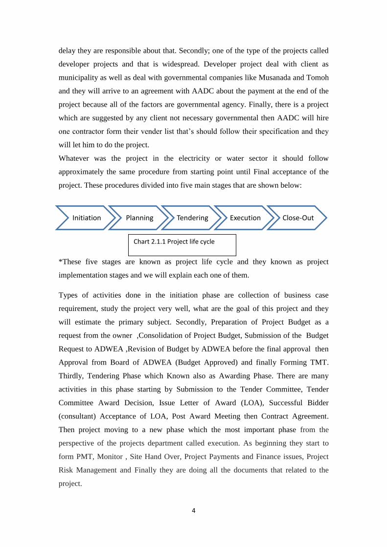
project. These procedures divided into five main stages that are shown below:
*These five stages are known as project life cycle and they known as project
implementation stages and we will explain each one of them.
Types of activities done in the initiation phase are collection of business case
requirement, study the project very well, what are the goal of this project and they
will estimate the primary subject. Secondly, Preparation of Project Budget as a
request from the owner ,Consolidation of Project Budget, Submission of the Budget
Request to ADWEA ,Revision of Budget by ADWEA before the final approval then
Approval from Board of ADWEA (Budget Approved) and finally Forming TMT.
Thirdly, Tendering Phase which Known also as Awarding Phase. There are many
activities in this phase starting by Submission to the Tender Committee, Tender
Committee Award Decision, Issue Letter of Award (LOA), Successful Bidder
(consultant) Acceptance of LOA, Post Award Meeting then Contract Agreement.
Then project moving to a new phase which the most important phase from the
perspective of the projects department called execution. As beginning they start to
form PMT, Monitor , Site Hand Over, Project Payments and Finance issues, Project
Risk Management and Finally they are doing all the documents that related to the
project.
Initiation Planning Tendering Execution Close-Out
Chart 2.1.1 Project life cycle
5
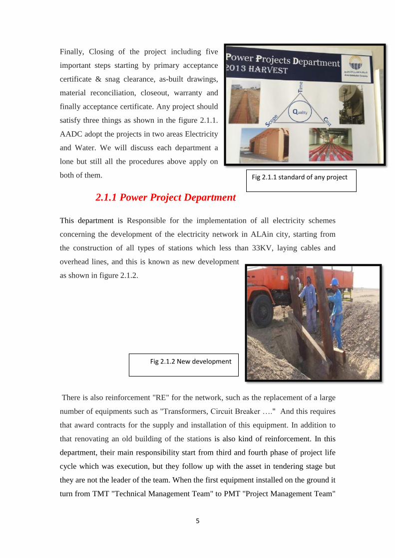
Finally, Closing of the project including five
important steps starting by primary acceptance
certificate & snag clearance, as-built drawings,
material reconciliation, closeout, warranty and
finally acceptance certificate. Any project should
satisfy three things as shown in the figure 2.1.1.
AADC adopt the projects in two areas Electricity
and Water. We will discuss each department a
lone but still all the procedures above apply on
both of them.
2.1.1 Power Project Department
This department is Responsible for the implementation of all electricity schemes
concerning the development of the electricity network in ALAin city, starting from
the construction of all types of stations which less than 33KV, laying cables and
overhead lines, and this is known as new development
as shown in figure 2.1.2.
There is also reinforcement "RE" for the network, such as the replacement of a large
number of equipments such as "Transformers, Circuit Breaker …." And this requires
that award contracts for the supply and installation of this equipment. In addition to
that renovating an old building of the stations is also kind of reinforcement. In this
department, their main responsibility start from third and fourth phase of project life
cycle which was execution, but they follow up with the asset in tendering stage but
they are not the leader of the team. When the first equipment installed on the ground it
turn from TMT "Technical Management Team" to PMT "Project Management Team"
Fig 2.1.1 standard of any project
Fig 2.1.2 New development

6
then they keep monitoring the project until completely finish then they close out the
project so mainly in this department 3 stages of the project life cycle were done and
the contents of each stages were explained and mentioned above*. Main focus of the
Power Project department that the contractor should not go out of the scope of work,
cost and specified time and all of these should be clear in any contract. For each
project there is project engineer, site engineer. But in large or VIP projects it should
be senior project engineer who supervise the project.
Project Engineer
• Interpretation of the project documents
• Following up the progress
• Quality assurance & control
• Performance assurance & control
• Approvals (Material, Drawing...etc)
Site Engineer:
• Ensure site works are as per the specs. (Quality, Quantity & Safety
wise)
• Shop drawing review
• Reviewing the measurement sheets
• Participating in the initial & final handing over
• Inspecting material delivered to site
Stations Types & Construction
All the Primary and Distribution stations were constructed by Power Project
department in AADC and they follow all standards that in the contracts such as the
ground of the station, quality of the cables and arrangement of the equipments inside
the stations. All of that were monitored by Site engineer. In addition to that,
construction of any station should do within the time stage by stage. Power Project
department receive the order form Asset then they applied on the ground and they
keep in contact with the contractor until warranty period finish then they handover the
stations to Operation and Maintenance department.
7
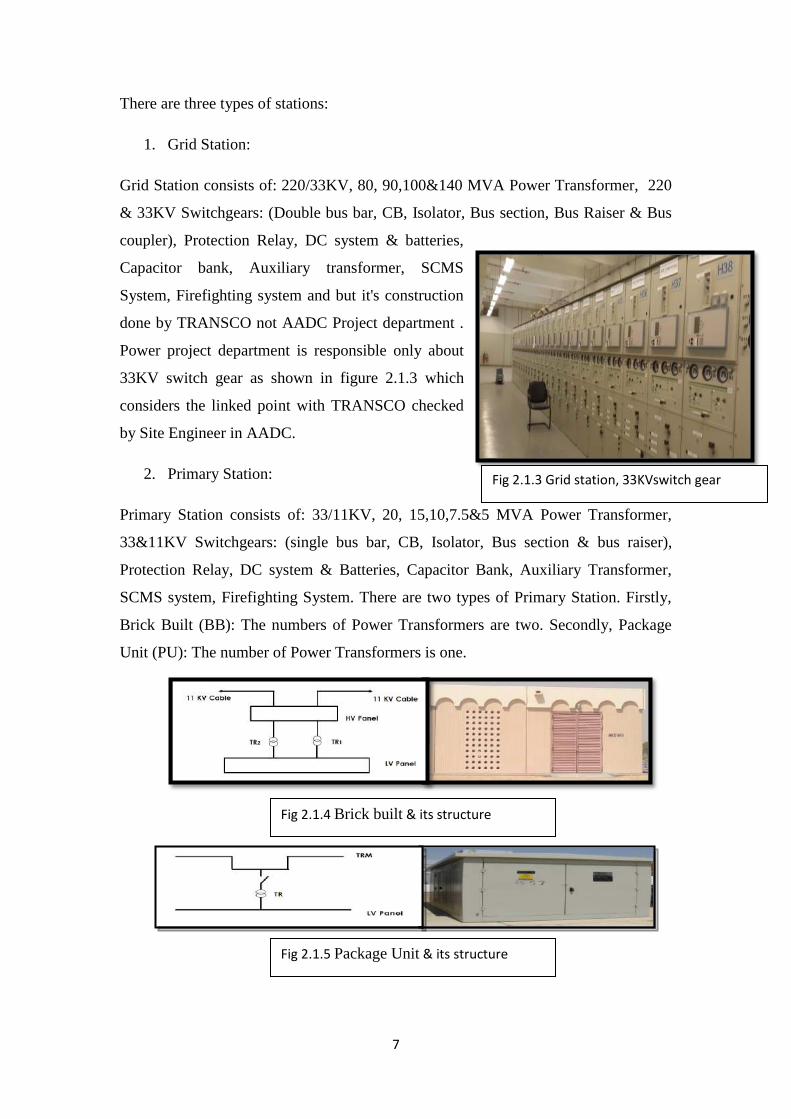
There are three types of stations:
1. Grid Station:
Grid Station consists of: 220/33KV, 80, 90,100&140 MVA Power Transformer, 220
& 33KV Switchgears: (Double bus bar, CB, Isolator, Bus section, Bus Raiser & Bus
coupler), Protection Relay, DC system & batteries,
Capacitor bank, Auxiliary transformer, SCMS
System, Firefighting system and but it's construction
done by TRANSCO not AADC Project department .
Power project department is responsible only about
33KV switch gear as shown in figure 2.1.3 which
considers the linked point with TRANSCO checked
by Site Engineer in AADC.
2. Primary Station:
Primary Station consists of: 33/11KV, 20, 15,10,7.5&5 MVA Power Transformer,
33&11KV Switchgears: (single bus bar, CB, Isolator, Bus section & bus raiser),
Protection Relay, DC system & Batteries, Capacitor Bank, Auxiliary Transformer,
SCMS system, Firefighting System. There are two types of Primary Station. Firstly,
Brick Built (BB): The numbers of Power Transformers are two. Secondly, Package
Unit (PU): The number of Power Transformers is one.
Fig 2.1.3 Grid station, 33KVswitch gear
Fig 2.1.4 Brick built & its structure
Fig 2.1.5 Package Unit & its structure
8
3. Distribution Sub-Station:
Distribution Station steps down the voltage from 11 KV to 0.415 KV. The types of
Distribution Sub-Station are shown in the following:
Brick Built (BB): consists of electrical equipment located in a brick or
concrete building that includes 600 Amp. The equipment are H.V & L.V Panel
and two transformers of size 1000 KVA or 1500 KVA.
Package Unit (PU): includes TRM, L.V Panel with fuses and transformer of
size 500 KVA or 1000 KVA or 1500 KVA.
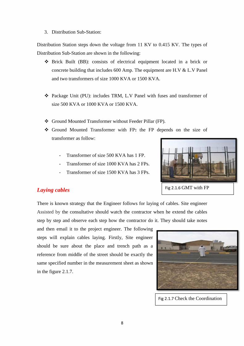
Ground Mounted Transformer without Feeder Pillar (FP).
Ground Mounted Transformer with FP: the FP depends on the size of
transformer as follow:
- Transformer of size 500 KVA has 1 FP.
- Transformer of size 1000 KVA has 2 FPs.
- Transformer of size 1500 KVA has 3 FPs.
Laying cables
There is known strategy that the Engineer follows for laying of cables. Site engineer
Assisted by the consultative should watch the contractor when he extend the cables
step by step and observe each step how the contractor do it. They should take notes
and then email it to the project engineer. The following
steps will explain cables laying. Firstly, Site engineer
should be sure about the place and trench path as a
reference from middle of the street should be exactly the
same specified number in the measurement sheet as shown
in the figure 2.1.7.
Fig 2.1.6 GMT with FP
Fig 2.1.7 Check the Coordination
9
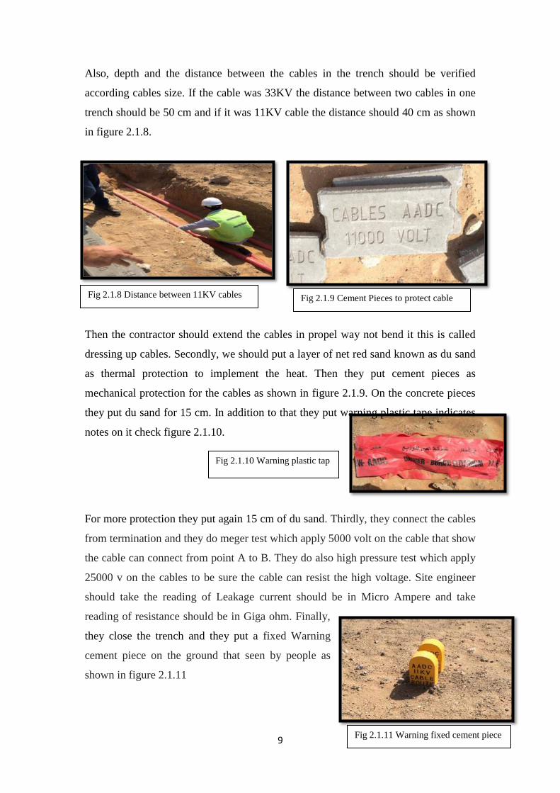
Also, depth and the distance between the cables in the trench should be verified
according cables size. If the cable was 33KV the distance between two cables in one
trench should be 50 cm and if it was 11KV cable the distance should 40 cm as shown
in figure 2.1.8.
Then the contractor should extend the cables in propel way not bend it this is called
dressing up cables. Secondly, we should put a layer of net red sand known as du sand
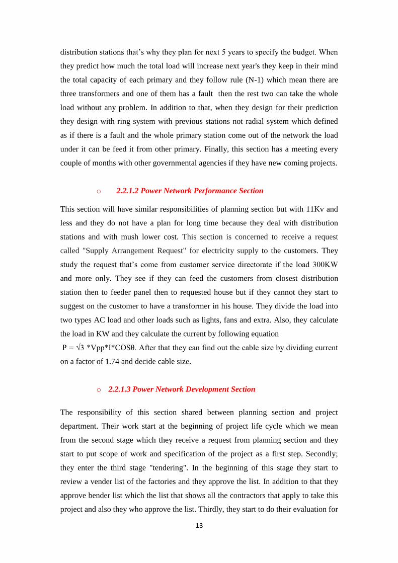
as thermal protection to implement the heat. Then they put cement pieces as
mechanical protection for the cables as shown in figure 2.1.9. On the concrete pieces
they put du sand for 15 cm. In addition to that they put warning plastic tape indicates
notes on it check figure 2.1.10.
For more protection they put again 15 cm of du sand. Thirdly, they connect the cables
from termination and they do meger test which apply 5000 volt on the cable that show
the cable can connect from point A to B. They do also high pressure test which apply
25000 v on the cables to be sure the cable can resist the high voltage. Site engineer
should take the reading of Leakage current should be in Micro Ampere and take
reading of resistance should be in Giga ohm. Finally,
they close the trench and they put a fixed Warning
cement piece on the ground that seen by people as
shown in figure 2.1.11
Fig 2.1.8 Distance between 11KV cables Fig 2.1.9 Cement Pieces to protect cable
Fig 2.1.10 Warning plastic tap
Fig 2.1.11 Warning fixed cement piece

10
2.1.2 Water Project Department
This department follows the exact procedures of power
project department. It's responsible of monitoring and
executing a new project for development of the water
network. 90% of their work is laying and extend water
pipe and their work is directly related with new project
of municipality because they want to ensure access of
water to the new homes. Project and site engineers will
have same responsibilities and tasks that they have in
power department but for water. They do a high pressure
test on the water pipe, flush and disinfect the pipe before they receive it from the
contractor. Also, project engineer review layout that submit it from contractor , check
all the required equipments and make sure that they are in their correct places on the
map and on the ground such as Fire extinguisher and valves.
2.1.3 Planning and control Section
Main responsibility of this section starts in the planning stage from project life cycle.
So they manage documents and transactions that’s transfer from Asset to the power or
water project department. They put and adjust some information then they award it to
either power or water department but they keep in contact with the project engineer
during period of the project not only in the planning stage.
Planning and Control section consists of four units:
- Power control unit
- Water control unit
- Account unit
- Clearance and Documentation unit
I will explain in detail the main duties of this section but I will not talk about water
control unit because I did not train with them. After the project award it from Asset
directorate their responsibility will start so they do not involve in starting of the
project "choosing contractor, total price extra..." . first of all they form TMT
"technical management team" and they choose the leader of PMT "project
Fig 2.1.12 Water Pipe

11
management team" who should be from project department. Also, they determine the
duration of the project and specify the starting date and completion date of the project.
They organize meeting called "Post award meeting" which the meet with the
contractor and project engineer who are responsible about this project. In addition to
that, they prepare a document called "Free issue material" if the contractor will use
some of the equipment from the store of AADC. They make an interview of all the
staff that will work with the contractor and they review the C.V for most of them
"Forman, electricians". Required from them to provide monthly report called
"Monthly Progress Report" that’s include scope of work, cost of the project ,what are
the percentage of completion and always should write the starting date of this project
in the report. They should submit also final organization chart that explain this project
in details and they who will agree if the contractor submit delay request based on the
final organization chart and monthly reports. Moving to account unit, this unit is
responsible about financial payments of the project departments either water or
power. Payments divide into two types. Firstly, to the consultative of the project and
this type will divide into two payments either on the design of the project or on
supervise on the site of the project. Secondly, payments to the contractor and will be
either for supply or installation of the equipments (60%, 40%) based on the fast
delivery while the civil work will have direct payments not like equipments. Finally,
Clearance and Documentation unit is responsible of help power & water control units
to do their charts, statistics and form of any official documents and reports.
2.2 Assets directorate
Assets directorate we conclude from the name that it is responsible for managing the
company's assets and we mean by management that managing all the administrative
work of the assets including other departments work such as supplying equipments ,
direct contact with the customers so its reflect the company's business. Also, this
directorate represents the company in the meeting with TRANSCO most of the time.
The main goal of the Asset directorate is to ensure supply of the power to the client in
the best way and that’s done by improving all the company's assets which is why the
provision of electricity which serve the customers at the end. In addition to that, Asset
directorate who is the one who divide ALAin city into four regions west that’s start
from ALyahar to ALKazna, North "from ALFoaa to ALFaqa" , south to um alzomol

12
and center of the city. Asset directorate manage all the asset in ALAin that belong to
33KV and less so it's responsible about 19 grid stations but not all of the equipment
only switch gear, 150 primary stations and around 15000 distribution stations
including all the equipments in these huge number of stations. Structure of Asset
directorate is shown below:
2.2.1 Power Network Planning & Development Department.
Because of the huge network in ALAin city and it's grow by huge different every year
so they divide this department in three separate sections and each section will take
certain responsibilities and focus on them.
o 2.2.1.1 Power Network Planning Section
This section is responsible about 33KV net work. Firstly, they do a plan every year
for next five years at least and they keep updating this plan monthly in case there is a
sudden case happen of development projects. They are a linked point with
transmission company "TRANSCO" and they keep informing Transco every year
about their plan for next five years to let TRANSCO prepare if there is huge different
in coming years. They focus on their plan about projects that related to 33KV which
mean building new primary stations and that need huge amount of money not like
Chart 2.2.1: AMD Organizational
structure
13
distribution stations that’s why they plan for next 5 years to specify the budget. When
they predict how much the total load will increase next year's they keep in their mind
the total capacity of each primary and they follow rule (N-1) which mean there are
three transformers and one of them has a fault then the rest two can take the whole
load without any problem. In addition to that, when they design for their prediction
they design with ring system with previous stations not radial system which defined
as if there is a fault and the whole primary station come out of the network the load
under it can be feed it from other primary. Finally, this section has a meeting every
couple of months with other governmental agencies if they have new coming projects.
o 2.2.1.2 Power Network Performance Section
This section will have similar responsibilities of planning section but with 11Kv and
less and they do not have a plan for long time because they deal with distribution
stations and with mush lower cost. This section is concerned to receive a request
called "Supply Arrangement Request" for electricity supply to the customers. They
study the request that’s come from customer service directorate if the load 300KW
and more only. They see if they can feed the customers from closest distribution
station then to feeder panel then to requested house but if they cannot they start to
suggest on the customer to have a transformer in his house. They divide the load into
two types AC load and other loads such as lights, fans and extra. Also, they calculate
the load in KW and they calculate the current by following equation
P = √3 *Vpp*I*COSθ. After that they can find out the cable size by dividing current
on a factor of 1.74 and decide cable size.
o 2.2.1.3 Power Network Development Section
The responsibility of this section shared between planning section and project
department. Their work start at the beginning of project life cycle which we mean
from the second stage which they receive a request from planning section and they
start to put scope of work and specification of the project as a first step. Secondly;
they enter the third stage "tendering". In the beginning of this stage they start to
review a vender list of the factories and they approve the list. In addition to that they
approve bender list which the list that shows all the contractors that apply to take this
project and also they who approve the list. Thirdly, they start to do their evaluation for

14
the contractors which divide into two types: Technical evaluation which supervised
by this section and they approve the contractors who get 70% and above. Other type is
commercial evaluation which about the price and this happens outside this section.
Also, they give approval on the price that specified by contractor in the middle of the
project if he wants extra money. If the contractor wants to change in the bell of
quantity he should communicate with development section only. Finally, they record
all the projects that are finish and done form project department in the company's
archives.
2.2.2 Asset Performance Department
This department divides into two sections; water section and power section. I was
trained in the power section only but both of them they follow the same procedures
which focusing on the Assets of the company and study them. Assets divide into two
types Non Moving Materials and Moving Materials and both of them invested by the
company. In the performance departments they concern about Non Moving materials
only such as power network and its equipments. There is some information and
features of the assets itself placed by performance department such as an
"identification number" this
number should be unique
for every equipment as
shown in figure 2.2.1.
Every asset should have an Introductory Certificate that’s explaining when the asset
was supplied and installed. Also, performance department study the asset if have a
value or just supplied and do not used. Most important thing that, they should specify
each location for each asset that related to AADC and records it in the system. In
addition to that the department monitors the whole network and doing monthly reports
Figure 2.2.1 serial number of Transformer

15
on the network to see the performance of the company based on number of shutdowns
in every year. Department works on the analysis and converts information to charts so
they can calculate the number of interruption and see which region have more
interruption. They look also to the reasons that cause the interruption especially for
over head line if its storm, fire or weak protection. This department is concerned
about inventory of materials in the store every year as shown in the figure 2.2.2 and
they classify wanted equipments to each department. One of the most important tasks
in the department is studying the life time cycle for most of the assets by analyzing
graph and they used some specific equation to know the performance of this asset like
for transformer: 𝑃𝑒𝑟𝑓𝑜𝑟𝑚𝑎𝑛𝑐𝑒 =40 𝑦𝑒𝑎𝑟𝑠−𝑢𝑠𝑒𝑑 𝐴𝑔𝑒
40 ∗ 100 and they analyze the
graphs to know life time cycle as shown in a sample graph below:
Also, when there is any FAT "Factory acceptance test" to buy any equipment
Engineer from this department should to be there and attend the test and accept the
equipments. They do the test on 10% of the quantity that will buy. Check Appendix A
2.2.3 Asset Information Department
Asset information department include two sections:
Asset information section
Asset Data management section
In the Data management section all the staff and engineers work on a maximo
program. They Store and archive the data on system & reviewing the layout. The
Graph 2.2.1 Figure 2.2.2 Stored Materials

16
Electricity Operation & Maintence Directorate
Operation & Maintence
Department
Network Managment
Division
Testing & Protection
Section
Field Service Department
Northern Region Section
Southern Region Section
Western Region Section
order of the steps, Data management section should finish their work before asset
information section because information section they need the data stored in the
system so they can work and see the latest update. Moving to the second section
"asset information section" which includes two units:
- GIS water
- GIS electricity
In the asset information section old maps which designed before year 2000 were
editing on the GIS system "Geographical information system". Main job is to keep
updating and entre new network specially cables and water pipes. In the GIS system
there are all the shapes and symbols that represent "primary stations, TRM,
transformers Extra... in GIS so they can also build all of the stations and edit them in
GIS.
2.3 Electricity Operation & Maintenance Directorate
This directorate mainly deals with AADC equipments for long time after the
warranty period from project department. They are the responsible of the
maintenance for all the equipments until its need to be replaced. Every department
or section is responsible about certain device. We stayed around 8 weeks in this
directorate. Organizational Structure of Electricity Operation & Maintenance
Directorate is shown below:
2.3.1 Operation and Maintenance Department
The responsibility of this department is to maintain most of the equipments such as all
the stations, cables and OHL. Also, they responsible about the operating and
shutdown any stations when there is fault happen and they isolate from termination.
O&M department is divided into five sections:
Chart 2.3.1 Organizational Structure of Electricity Operation & Maintenance Directorate

17
- Cable Section.
- OHL Section.
- Substation Maintenance Section.
- Operation Section.
- Maintenance Planning Section
2.3.1.1 Cable Section
This section is very important because most of the network in ALAin is cables so its
need very well maintenance, expert engineers, labors for digging and modern
equipments to find the fault quickly because its underground around one meter. Their
responsibilities start when there is a fault happen to 33, 11 KV, and LV .Operation
section will send a request to them to specify the fault location approximately by GIS
as shown in figure 2.3.1 so the operation section can isolate the damage cables for
them from two termination side from the substations. Cable section asks operation
section about SFT "sanction for test" as shown in figure 2.3.2 which mean this cable
is safe to work on it. They do this process in either situation fault happen or
identification which they consider the main responsibilities of cable sections.
First of all I will explain what are the procedures and
steps that follow when the fault happen. They start by
doing burn process which help to found which one of the
phase is damage. When the engineer start to do burning
in the test van for each phase, the damage phase will
Figure 2.3.1 GIS System Figure 2.3.2 SFT request
Figure 2.3.3 Burn process
18
show increasing in the leakage current and it will show small value of volt as shown
in the figure 2.3.3 above.
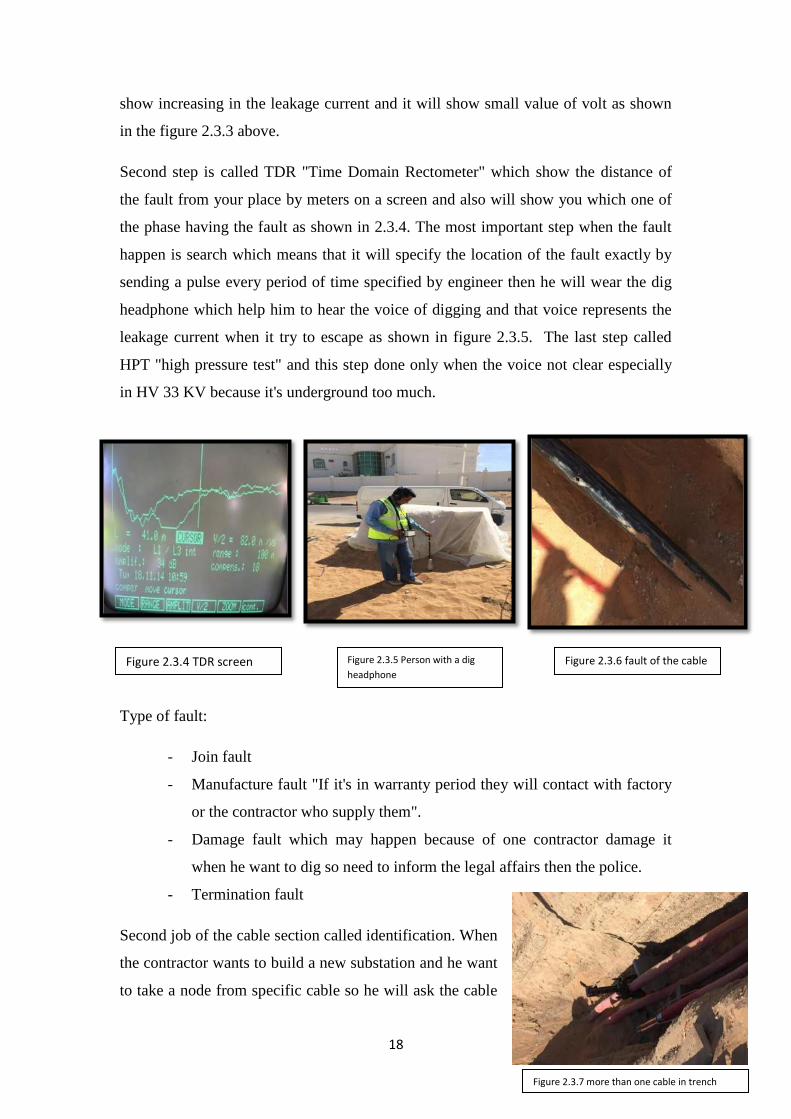
Second step is called TDR "Time Domain Rectometer" which show the distance of
the fault from your place by meters on a screen and also will show you which one of
the phase having the fault as shown in 2.3.4. The most important step when the fault
happen is search which means that it will specify the location of the fault exactly by
sending a pulse every period of time specified by engineer then he will wear the dig
headphone which help him to hear the voice of digging and that voice represents the
leakage current when it try to escape as shown in figure 2.3.5. The last step called
HPT "high pressure test" and this step done only when the voice not clear especially
in HV 33 KV because it's underground too much.
Type of fault:
- Join fault
- Manufacture fault "If it's in warranty period they will contact with factory
or the contractor who supply them".
- Damage fault which may happen because of one contractor damage it
when he want to dig so need to inform the legal affairs then the police.
- Termination fault
Second job of the cable section called identification. When
the contractor wants to build a new substation and he want
to take a node from specific cable so he will ask the cable
Figure 2.3.4 TDR screen Figure 2.3.5 Person with a dig
headphone
Figure 2.3.6 fault of the cable
Figure 2.3.7 more than one cable in trench

19
section to identify to him the cable if there is more than one cable in the trench as
shown in figure 2.3.7.
Cable section will follow certain steps to identify the cable:
- Ask the operation section to isolate from termination and sign sanction for
test paper
- Fix a sender on the wanted cable in one of the terminals only by putting a
red mark in the device on one phase of the cable and black & green to the
ground as shown in figure 2.3.8.
- Other terminal in the second substation should be connected to the earth by
operation section.
a) Engineer takes the receiver device with him to the site and he put it on the many
cables. The signal will be strongest on the wanted cable as shown in figure 2.3.9
and it will indicate two colors red and green. If the receiver in the same direction
of the grounded termination the signal will be green otherwise will be red .We
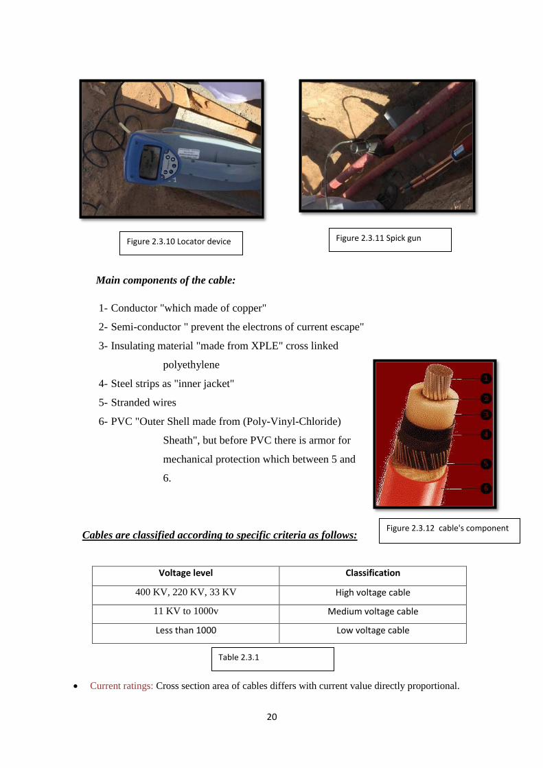
can double check by using device called locater and its shows the signal without
the direction in figure 2.3.10.
Identification was done and now the contractor wants to cut the cable to take a node
for his connection but that done by cable section only by using spick gun or hydrogen
gun in figure 2.3.11 that fix it on the wanted cable then engineer will pull the bullet by
long thread then the contractor can cut the cable very well and make his connection.
Figure 2.3.8 Sender device Figure 2.3.9 Receiver device
20
Main components of the cable:
1- Conductor "which made of copper"
2- Semi-conductor " prevent the electrons of current escape"
3- Insulating material "made from XPLE" cross linked
polyethylene
4- Steel strips as "inner jacket"
5- Stranded wires
6- PVC "Outer Shell made from (Poly-Vinyl-Chloride)
Sheath", but before PVC there is armor for
mechanical protection which between 5 and
6.
Cables are classified according to specific criteria as follows:
Classification Voltage level
High voltage cable 400 KV, 220 KV, 33 KV
Medium voltage cable 11 KV to 1000v
Low voltage cable Less than 1000
Current ratings: Cross section area of cables differs with current value directly proportional.
Figure 2.3.10 Locator device Figure 2.3.11 Spick gun
Figure 2.3.12 cable's component
Table 2.3.1

21
Insulation Type: Three types of cables are used according to the insulation material: (XLPE
and PVC).
Number of cores: A run of cable may consist of 1, 2, 3, 4, or 5 cores.
Conductor type: The type of conductor used in cables could be Copper or Aluminum.
2.3.1.2 OHL Section
This section is responsible of the 33/11KV OHL network in Al Ain city so it's feed
too many distribution stations that’s why they specify a special section for it because
it consider a second most important source of distribution in the network and as a first
transmission way because of the small amount of losses. In AADC they use copper of
aluminum conductor and the cross section of the conductor are: 35, 70, 95, 120, and
150 mm2. There are around 6000 KM of OHL in ALAin city especially in the external
regions that why this section consists of two units:
- Inspection and monitoring unit
- Maintenance unit
Inspection and monitoring unit is responsible about scan over ALAin city especially
after the storm they keep patrolling, observe if there are any problems and if they
found any problem they reported quickly to maintenance unit but some time there is
temporary fault so they will solve it. When maintenance unit receive call or report
from inspection unit, they will contact with operation section to isolate the line for
them from both terminals of the line, grounded to the earth around 7 m from each side
as a safety for them and ask for SFT then they will do their maintenance on the
damage equipment or the pole itself.
OHL Components: Check Appendix B
1- OHL switches:
The main aim of OHL switches is delivering energy safety, efficiency and reliability.
- VMS: vertical mountain switch
When we have OHL and there and there is any interruption such as street ans we want
to complete we use VMS
- VMSF: vertical mountain switch with fuse will have the same purpose but
with fuse
22
- Master Head switch (MHS)
From its name master that mean its control the whole line from pole to pole or it give
you a choice to open the line from middle
2- Auto-re-closer (CT)
Is a circuit breaker prepared with a mechanism that can automatically close the
breaker after it has been opened due to a transient fault. It will make several pre-
programmed attempts to re-energize the line. If the transient fault has cleared, the
auto-re-closer's circuit breaker will remain closed and normal operation of the power
line will resume. If the fault is a permanent fault, the auto-recloser will exhaust its
pre-programmed attempts to re-energize the line and remain tripped off until
manually instructions.
3- Sectionalize (VT)
It operates when a line is "dead" because of the operation of an auto-re-closer or
breaker along the line. Sectionalizes serve to isolate a section of line while allowing
the remainder of the circuit to remain energized.
4- PMT
it is step-down TR. The PMT should have some specification such as TR power 200
KVA
5- A Lighting Arrestor/ Surge Arrester
Lighting Arrestor is located in the top of the pole. It used to protect the cable and
PMT. It consists of insulation (porcelain), bracket and fault indicator.
6- Pin for 11KV or Post insulator for 33KV
It's made from porcelain or polymer which used as a protection to the pole itself from
the fire.
7- Kicking blocks.
When they start to construct Hpole in new project or replace one of them they use
blocks to fix the pole very well under the ground.
8- Earth Fault Indicator (EFI)
23
Is designed to indicate the short circuit fault and identify fault location. It accurate
fault indication enables the operator to identify the fault sections easily and isolate
them in time.
2.3.1.3 Operation Section
This section is the busiest section in O&M department because its serve all other
sections when they want to do their work. Main responsibility of this section is to
isolate the fault equipment and restore the supply to the customer so they isolate the
fault and feed the customers from other substations according to ring system. They
identify the fault by a device called earth fault indicator which appear on the door of
the stations. When the light on in the device that’s mean the fault happens after this
substation. Operation section is responsible for all shut down, energize, isolate fault in
the network. The main challenge for the operation section is to return back the load as
soon as possible in emergency time. This section consist of two Units: planned
shutdown and UN planned "emergency" unit.
- Planned shutdown: planned before such as operate new substation for project
or contractor want to do join in the cables or fix something in the station.
- Emergency unit: fault happen in the network "cables, OHL or equipments in
the stations" because of fire or storm.
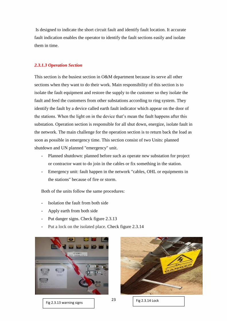
Both of the units follow the same procedures:
- Isolation the fault from both side
- Apply earth from both side
- Put danger signs. Check figure 2.3.13
- Put a lock on the isolated place. Check figure 2.3.14
Fig 2.3.13 warning signs Fig 2.3.14 Lock
24
- Give safe document which include three types
PTW "permit to work". If it was on the earth the other section's
engineers or labors cannot remove the earth off.
SFT "sanction for test". He can remove the earth but with permission
from operation section.
LAB "Limit access permit". He can enter the station but without doing
anything or just to check simple equipment.
2.3.1.4 Substation Maintenance Section
This section is responsible about 80% of the equipments in the substation. This
section divides their work into Corrective Maintenance "CM", Condition Base
Maintenance (CBM) and Reliability Center Maintenance. Corrective maintenance
mean emergency that’s mean fault happen in of the equipments that related to this
section. Condition Base Maintenance is a group contains engineer, assistant engineer
and technicians to do inspections on substations and check the following:
- Circuit Breaker (oil , vacuum and SF6)
- Transformer with whole the equipments ( tap changer, body of the
transformer, its oil and extra…) as shown in the figure 2.3.15
- Silicajel which define as small grains absorb humidity from the body of the
transformer it's have two color white or blue, the white when its damage or
need replacement change to brown while blue change to pink color.
- Check the whole buttons of LV and HV panels, if some of them need
replacement.
If they found something danger they reported to the corrective maintenance as soon as
possible but filling oil, refresh circuit breaker and clean the transformer from their
specialty as shown in figure 2.3.16.

25
Reliability center maintenance "RCM" collects the information from CM and CBM
then they analyze it, study it and finally they put commandments to the section to
change the company that supply this type of equipments according to increase number
of defects.
These section deals with same equipments that do same purpose but each company
manufacture it in different way. I will identify related equipments to this section
Type of cooling for the transformer:
- ONAN "oil natural air natural"
- ONAF "oil natural air forced"
- OFAF "oil forced air forced"
Difference between isolator and circuit breaker
- Isolator: when we want to close it or open it , we should do that with the load
is off because it does not have a media to extinguish the spark.
- Circuit breaker: we can open it or close it even with the load is connected
Difference between bus coupler, bus section and bus riser check Appendix C.
- Bus coupler: connect between two bus bars
- Bus section: connect between two separate piece of bus bar it self
- Bus Riser: complete the connection so if the first load connected on bus bar 1
then I will use bus riser to connect load 2 on bus bar 2.
Fig 2.3.15 Filling the Transformer
Fig 2.3.16 Fill CB
26
2.3.1.5 Maintenance Planning Section
Planning section is developing and scheduling all maintenance activities for
respective sections. All scheduled activities are done after coordinating with Network
Operation Department. In addition to that they organize between all the sections in
O&M department if one of the sections needs to do any shutdown what are the effect
on other sections.
2.3.2 Field Service Department
This department serves governmental agencies and ministries such as hospitals,
palaces, street lights and any other governmental services. They have all the
equipments that O&M department has except OHL section so they can manage their
work alone but also sometimes provide help to other departments to supply the
electricity to the customers in emergency time. This department includes two sections:
- Street light section
- VIP section
2.3.2.1 Street light section
Street light Section responsible about all the streetlight columns in ALAin city and its
external regions. Street light Section consists of two Units Patrolling & Emergency
Unit "accidents of cars, check the damage and Maintenance Unit. Patrolling unit
receives reports from DMS and then they transfer it to maintenance unit. There are
two types of light used in AADC (high pressure sodium & metal halite) and their
brightness {150w, 200w, 600w, 700w, 1000w, 2000w}
- For Neighborhoods 150 w were used.
- For highways 1000 & 2000 w were used
They have an indication for each color such as :
- ww for purely white
- yy for yellow
- yw between the two color
27
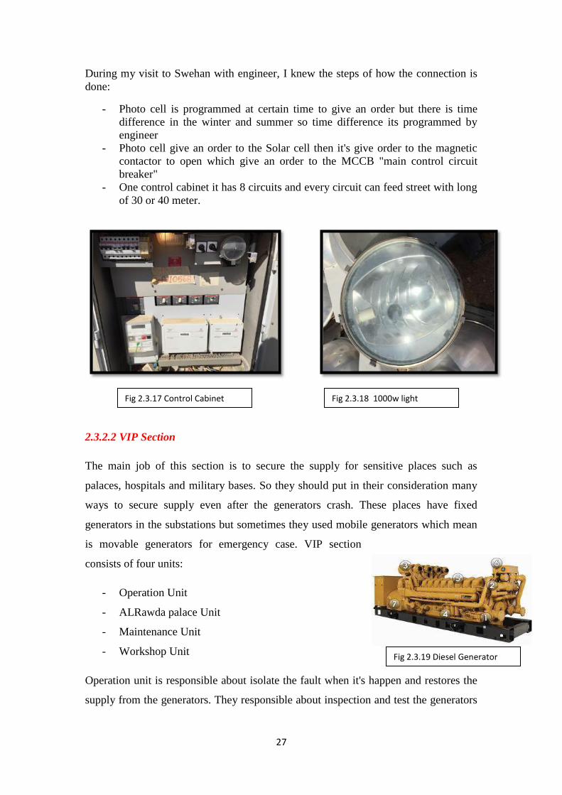
During my visit to Swehan with engineer, I knew the steps of how the connection is
done:
- Photo cell is programmed at certain time to give an order but there is time
difference in the winter and summer so time difference its programmed by
engineer
- Photo cell give an order to the Solar cell then it's give order to the magnetic
contactor to open which give an order to the MCCB "main control circuit
breaker"
- One control cabinet it has 8 circuits and every circuit can feed street with long
of 30 or 40 meter.
2.3.2.2 VIP Section
The main job of this section is to secure the supply for sensitive places such as
palaces, hospitals and military bases. So they should put in their consideration many
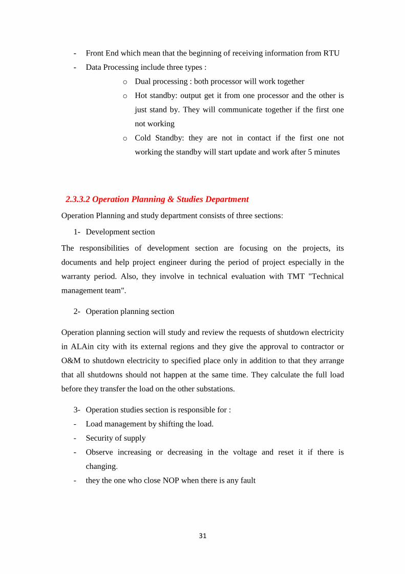
ways to secure supply even after the generators crash. These places have fixed
generators in the substations but sometimes they used mobile generators which mean
is movable generators for emergency case. VIP section
consists of four units:
- Operation Unit
- ALRawda palace Unit
- Maintenance Unit
- Workshop Unit
Operation unit is responsible about isolate the fault when it's happen and restores the
supply from the generators. They responsible about inspection and test the generators
Fig 2.3.17 Control Cabinet Fig 2.3.18 1000w light
Fig 2.3.19 Diesel Generator
28
if its response when fault happen of not. Also, they operate mobile generators
"movable generators" when it's emergency happen.
ALRawda palace unit has all the powers which in three other units have which mean
that they have a maintenance team, operation team and mobile generators. They do
inspection and test for the generators every three months because it’s a very important
place.
Maintenance unit which is receive the request from operation unit when they record
any strange thing or damage equipments or the generators do not response in normal
way. Maintenance unit is responsible about all the palaces, hospitals except ALrawda
palace because they have their own team. Maintenance unit divide the fault into three
types Mechanical, Electrical and Control & Instrument so they send particular team.
Workshop unit is very important unit because as I said this section consider a separate
section from AADC they have most of the equipments and they do not depend on the
other sections so they need a workshop to do some test on the mobile generators to fix
them, on Relays and how its response when there is fault happen and on the other
equipments.
Type of the generators and how its work:
- Manual generators
Engineer should be sure that there is no supply for electricity from
other source
Convert MTS "Manual Transfer Switch" button from main to off and
then put it on the generator mode.
Fix frequency and the volt manually and then turn on the generator
manually
- Semi Automatic
Sensing voltage relay will sense if there is any change in voltage or frequency and it
will activate automatically by sending a signal to LMS "load management system" to
trip all outgoing feeders in the substations and then give order to CB of the generators
to close then the generators will start. After that Voltage and frequency will be stable
after few minute. Generators will feed bus bar and return the outgoing feeders one by

29
one according to popularity. When the main incomer back to supply, the engineer
should switch the MTS to the main supply side then the generators will shut down
after 5 minutes.
- Full Automatic generators
It will follow same procedures of semi automatic generators but it has a switch called
ATS "Automatic Transfer Switch" that’s mean no need for switching the MTS
manually when the main incomer back to supply the substation because it will transfer
the load automatically by ATS. There is a system called Full Automatic with back
synchronizing. The customers will not feel the shutdown when the main incomer back
to the service because the generators and main supply they will share the load until
main incomer take all of it. there is an interruption of electricity happen when the
generator start to work and that can be a void it by UPS system which define as a
storage of the DC then its converted to AC by device called inverter but it works for
specific time only. Reasons of providing these two systems patients in the hospitals
who cannot breathing without electrical equipments even for seconds or when the
doctors make an operation.
2.3.3 Network Management Division
This Division with all departments is responsible about monitoring the network and
detect if there is anything that is unusual in the net work which include all the primary
and distribution substations. They monitor load, frequency, transformer and every
single equipment in the network so they distribute their work among many
departments. The structure of this division is shown below:
NMD
SCADA Department
Software section
Hardware Section
Telecommunication section
Network Opration
Depaertment
Control center section
Operation Planning &studies
Development section
Operation planning section
Operation studies section
Chart 2.3.1 NMD organizational structure

30
2.3.3.1 SCADA Department
SCADA stand for supervisory control And Data Acquisition
2.3.3.1.1 Hardware Section
Hardware section is responsible of transducers (analog input
for RTU) , command relays ( digital output for RTU ) and
status relays ( digital input for RTU ) and RTU itself .
RTU will collect all the information from these devices which they define as follow:
Transducer: analog input device locate it always after CT and VT. Its purpose to step
down voltage and current because of the electronic devices that cannot read large
values.
Command relay: two relays to switch on / off the circuit breaker.
Status relays: contain of all relays "earth fault, over current and over voltage to check
values of power, voltage and current.
2.3.3.1.2 Telecommunication Section
Telecommunication section is responsible to transfer the information send
by RTU in substation to software section. They responsible about the
media that carry information to the software section. There are two types
of media that they can send the information through it either wireless or
cables. Wireless either by WLAN or GPRS "Etisalat" and that commonly
used in AADC because it can send for long distance while cables will be
costly for long distance. Cables divide into copper or Fiber Optic cable
"FOC" as shown in figure 2.3.21
2.3.3.1.3 Software Section
Software section is responsible of receiving signals from RTU then they analyze it
and convert them to information that can be understandable and readable. After that,
they send this information to control section and it will appear to them on the screen
so they follow the following procedures:
Fig 2.3.20 RTU
Fig 2.3.21 FOC
31
- Front End which mean that the beginning of receiving information from RTU
- Data Processing include three types :
o Dual processing : both processor will work together
o Hot standby: output get it from one processor and the other is
just stand by. They will communicate together if the first one
not working
o Cold Standby: they are not in contact if the first one not
working the standby will start update and work after 5 minutes
2.3.3.2 Operation Planning & Studies Department
Operation Planning and study department consists of three sections:
1- Development section
The responsibilities of development section are focusing on the projects, its
documents and help project engineer during the period of project especially in the
warranty period. Also, they involve in technical evaluation with TMT "Technical
management team".
2- Operation planning section
Operation planning section will study and review the requests of shutdown electricity
in ALAin city with its external regions and they give the approval to contractor or
O&M to shutdown electricity to specified place only in addition to that they arrange
that all shutdowns should not happen at the same time. They calculate the full load
before they transfer the load on the other substations.
3- Operation studies section is responsible for :
- Load management by shifting the load.
- Security of supply
- Observe increasing or decreasing in the voltage and reset it if there is
changing.
- they the one who close NOP when there is any fault
32
2.3.3.3 Network Operation Department
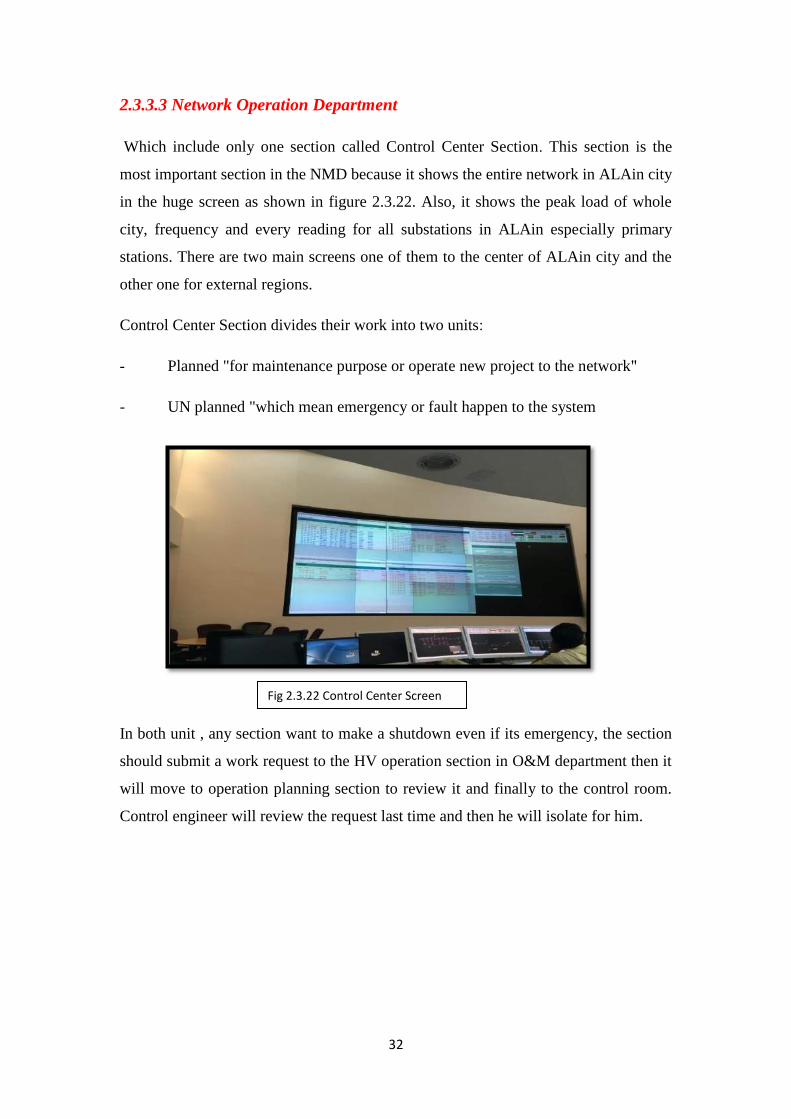
Which include only one section called Control Center Section. This section is the
most important section in the NMD because it shows the entire network in ALAin city
in the huge screen as shown in figure 2.3.22. Also, it shows the peak load of whole
city, frequency and every reading for all substations in ALAin especially primary
stations. There are two main screens one of them to the center of ALAin city and the
other one for external regions.
Control Center Section divides their work into two units:
- Planned "for maintenance purpose or operate new project to the network"
- UN planned "which mean emergency or fault happen to the system
In both unit , any section want to make a shutdown even if its emergency, the section
should submit a work request to the HV operation section in O&M department then it
will move to operation planning section to review it and finally to the control room.
Control engineer will review the request last time and then he will isolate for him.
Fig 2.3.22 Control Center Screen
Fig 2.3.22 Control Center Screen

33
Chapter Three: Proposal for a Graduation Project
At the beginning of year 2015 which exactly from 1/1/2015 there will be an increase
in the price of electricity after the ADWEA has an approval from executive board.
Increasing in the Electricity price for the local will be if his consumption reaches 400
KW and above per month there will be more charge about 5 cents for every one KW
while for the residents they will pay production rate for every 1 KW if they reach up
to 200KW per month. Most of the people they do not know how much they will
consume per a month or if they reach 400 KW to reduce their consumption especially
old men and women.
We know that there is already a counter outside in every house that checked by
AADC engineers. This defined as electricity meter or energy meter, is a device that
measures the amount of electrical energy consumed by homes.
I propose a device that gives an alert to the owner that warning him that he will
exceed the limit soon. Simply this device like a sensor should be fixed in the main DP
of the house "counter". Then it should program to sense at a certain consumption rate
according to the customers for example for the locals at 350KW so when the energy
meter reaches up to 350KW the sensor will sense this number and direct send a text
message to the mobile of the owner "reduce your consumption …….".
There are other valid equipments that can be added to increase the performance of
reduce the consumption such as putting a monitor in the house itself same as monitor
in the DMS building of AADC. This monitor do the same purpose of the screen in the
DMS which show the consumption rate of this house and customer put this screen in
the living room when the consumption rate reach 350KW the color that show the
number "load" change to red in the screen. Also, in this screen may have an
indication about which room has the most consumption so the customers can reduce
the rate before he exceeds the limit.

34
Chapter Four: Conclusions &Recommendations
In the end, Training course was very useful to us. It was a link between 4 years of
study and experimental work in the field. AADC is among the best place for electric
engineers to take the training course with them because their job is to distribute water
and electricity to the customers so trainee will see all the steps of electricity's
distribution and they will have an idea about transmission & Generation. During 16
weeks of training with them, I moved among two directorates and one division started
by Project Delivery Division, Asset Management directorate and Electricity operation
and maintains directorate. During the training gained a lot of experience and skills
such as what are the basic procedures to do any kind of projects, How to manage the
asset and plan for the future in the asset directorate and field experience, see most of
the electrical equipments that I never see before, identify the job of each one and how
they monitor the whole network of ALAin from one place all of that was taken in
electricity operation and maintains directorate and its departments. Finally it was the
most enjoyable and helpful course.
Recommendation:
- For AADC
I trained around 4 weeks in Asset directorate and form my opinion this period
of time is too much because most of their work as management work so if they
reduce it to one or two weak
Send an Email to each department & directorate to inform them about trainees
because when we move from directorate to another they ask for official letter
or emails from hr.
Add to the training schedule Customer service directorate because it's too
important for trainees to deal direct with customers.
- For UAEU
Change submission of the report from Iwill to black bored because
Iwill site shutdown every couple of days.
Increase number of meeting in the course that is before training course

35
References
http://www.aadc.ae/en/pages/AboutAADC.aspx
www.wikipedia.com
http://emiratestransformer.com/
http://www.ducab.com/
Some information from the reports that given by AADC engineers
36
Appendix A (Transformer's Factory)
Fig A.1 record measurements Fig A.2 opens TR from inside
Fig A.3 measure HV phase with LV phase Fig A.4 manufacture of TR

37
Appendix B (OHL Components)
Fig B.1 PMT Fig B.2 Pin insulator
Fig B.3 Master Head switch Fig B.4 Auto-Recloser
38
Appendix C (substations equipments)
Fig C.1 TRM Fig C.1 RMU Feeder Type
Fig C.3 Bus Riser Fig C.4 Bus coupler
39
Appendix D
United Arab Emirates University
College of Engineering - Industrial Training Unit
Industrially Suggested Senior Project
Student Name: Hamad Mohammed Ali ALSaadi Student ID: 201010114
Department: Electrical Engineering Semester & Year: Fall 2014
Company/Organization: AADC
Industrial Supervisor: Dr. Mousa Hussain
Project Description: At the beginning of year 2015 which exactly from 1/1/2015 there will be
an increase in the price of electricity after the ADWEA has an approval from executive board.
Increasing in the Electricity price for the local will be if his consumption reaches 400 KW and
above per month there will be more charge about 5 cents for every one KW while for the
residents they will pay production rate for every 1 KW if they reach up to 200KW per month.
Most of the people they do not know how much they will consume per a month or if they
reach 400 KW to reduce their consumption especially old men and women.
We know that there is already a counter outside in every house that checked by AADC
engineers. This defined as electricity meter or energy meter, is a device that measures the
amount of electrical energy consumed by homes.
I propose a device that gives an alert to the owner that warning him that he will exceed the
limit soon. Simply this device like a sensor should be fixed in the main DP of the house
"counter". Then it should program to sense at a certain consumption rate according to the
customers for example for the locals at 350KW so when the energy meter reaches up to
350KW the sensor will sense this number and direct send a text message to the mobile of the
owner "reduce your consumption …….".
There are other valid equipments that can be added to increase the performance of reduce the
consumption such as putting a monitor in the house itself same as monitor in the DMS
building of AADC. This monitor do the same purpose of the screen in the DMS which show
the consumption rate of this house and customer put this screen in the living room when the
consumption rate reach 350KW the color that show the number "load" change to red in the
screen. Also, in this screen may have an indication about which room has the most
consumption so the customers can reduce the rate before he exceeds the limit.


![partial] fulfillment Town](https://img.pdfslide.us/doc/110x75/61cbd0e20c1fcf7e016f4ea2/partial-fulfillment-town.jpg)