Embed Size (px)
Citation preview

Final report RO-2013-103 and RO-2014-103: Passenger train
collisions with Melling Station stop block, 15 April 2013 and 27 May 2014

The Transport Accident Investigation Commission is an independent Crown entity established to
determine the circumstances and causes of accidents and incidents with a view to avoiding similar
occurrences in the future. Accordingly it is inappropriate that reports should be used to assign fault or
blame or determine liability, since neither the investigation nor the reporting process has been
undertaken for that purpose.
The Commission may make recommendations to improve transport safety. The cost of implementing
any recommendation must always be balanced against its benefits. Such analysis is a matter for the
regulator and the industry.
These reports may be reprinted in whole or in part without charge, providing acknowledgement is made
to the Transport Accident Investigation Commission.

Final Report
Rail inquiries RO-2013-103 and RO-2014-103
Passenger train collisions with Melling Station stop block, 15 April
2013 and 27 May 2014
Approved for publication: November 2016

Transport Accident Investigation Commission
About the Transport Accident Investigation Commission
The Transport Accident Investigation Commission (Commission) is a standing commission of inquiry and
an independent Crown entity responsible for inquiring into maritime, aviation and rail accidents and
incidents for New Zealand, and co-ordinating and co-operating with other accident investigation
organisations overseas. The principal purpose of its inquiries is to determine the circumstances and
causes of occurrences with a view to avoiding similar occurrences in the future. Its purpose is not to
ascribe blame to any person or agency or to pursue (or to assist an agency to pursue) criminal, civil or
regulatory action against a person or agency. The Commission carries out its purpose by informing
members of the transport sector and the public, both domestically and internationally, of the lessons
that can be learnt from transport accidents and incidents.
Commissioners
Chief Commissioner Helen Cull QC (until 8 July 2016)
Deputy Chief Commissioner Peter McKenzie, QC
Commissioner Jane Meares
Commissioner Stephen Davies Howard
Key Commission personnel
Chief Executive Lois Hutchinson
Chief Investigator of Accidents Captain Tim Burfoot
Investigator in Charge Barry Stephenson
General Counsel Cathryn Bridge
Email [email protected]
Web www.taic.org.nz
Telephone + 64 4 473 3112 (24 hrs) or 0800 188 926
Fax + 64 4 499 1510
Address Level 16, 80 The Terrace, PO Box 10 323, Wellington 6143, New Zealand

Important notes
Nature of the final report
This final report has not been prepared for the purpose of supporting any criminal, civil or regulatory action
against any person or agency. The Transport Accident Investigation Commission Act 1990 makes this
final report inadmissible as evidence in any proceedings with the exception of a Coroner’s inquest.
Ownership of report
This report remains the intellectual property of the Transport Accident Investigation Commission.
This report may be reprinted in whole or in part without charge, provided that acknowledgement is made
to the Transport Accident Investigation Commission.
Citations and referencing
Information derived from interviews during the Commission’s inquiry into the occurrence is not cited in
this final report. Documents that would normally be accessible to industry participants only and not
discoverable under the Official Information Act 1982 have been referenced as footnotes only. Other
documents referred to during the Commission’s inquiry that are publicly available are cited.
Photographs, diagrams, pictures
Unless otherwise specified, photographs, diagrams and pictures included in this final report are provided
by, and owned by, the Commission.
Verbal probability expressions
The expressions listed in the following table are used in this report to describe the degree of probability
(or likelihood) that an event happened or a condition existed in support of a hypothesis.
Terminology (adopted from the Intergovernmental
Panel on Climate Change)
Likelihood of the
occurrence/outcome
Equivalent terms
Virtually certain > 99% probability of occurrence Almost certain
Very likely > 90% probability Highly likely, very probable
Likely > 66% probability Probable
About as likely as not 33% to 66% probability More or less likely
Unlikely < 33% probability Improbable
Very unlikely < 10% probability Highly unlikely
Exceptionally unlikely < 1% probability

Melling 2 train
Location of accidents
Western
Hutt Station
Melling
Station

Contents
Abbreviations .................................................................................................................................................... ii
Glossary .....................................................................................................................................................iii
Data summary .................................................................................................................................................. iv
1. Executive summary .................................................................................................................................. 1
2. Conduct of the inquiry .............................................................................................................................. 3
2.1. Notification and investigation ..................................................................................................... 3
Interim report .............................................................................................................................. 3
Brake tests in low adhesion ....................................................................................................... 3
3. Factual information .................................................................................................................................. 5
3.1. Background .................................................................................................................................. 5
Friction brakes ............................................................................................................................ 6
Dynamic brakes .......................................................................................................................... 6
Pneumatic brakes ....................................................................................................................... 6
Emergency brake ........................................................................................................................ 7
Melling Station ............................................................................................................................ 7
3.2. Narrative ...................................................................................................................................... 7
Melling 1 accident ...................................................................................................................... 7
Melling 2 accident ...................................................................................................................... 8
3.3. The drivers ................................................................................................................................. 10
3.4. Computer controlled brake system .......................................................................................... 10
3.5. Rail adhesion ............................................................................................................................. 11
3.6. Wheel slide protection system .................................................................................................. 11
3.7. Similar accidents ....................................................................................................................... 12
England ...................................................................................................................................... 12
Melbourne, Australia ................................................................................................................ 12
Queensland, Australia .............................................................................................................. 12
4. Analysis ................................................................................................................................................... 13
4.1. Introduction ................................................................................................................................ 13
4.2. Interpretation of evidence ......................................................................................................... 13
Melling 1 .................................................................................................................................... 13
Melling 2 .................................................................................................................................... 14
Conditions common to both accidents .................................................................................... 14
4.3. Management of infrastructure risk at terminating stations.................................................... 15
The line speed limit ................................................................................................................... 15
The stop block ........................................................................................................................... 15
The overhead power ................................................................................................................. 15
Train brake performance .......................................................................................................... 16
Low adhesion brake test programme ...................................................................................... 16
New Zealand standards for train brakes ................................................................................. 17
4.4. Driver training ............................................................................................................................ 18
5. Findings .................................................................................................................................................. 20

6. Safety actions ......................................................................................................................................... 21
6.1. General ....................................................................................................................................... 21
6.2. Safety actions addressing safety issues identified during an inquiry .................................... 21
6.3. Safety actions addressing other safety issues ........................................................................ 21
7. Recommendations ................................................................................................................................. 22
7.1. General ....................................................................................................................................... 22
7.2. Recommendations to KiwiRail .................................................................................................. 22
Speed restrictions for terminal stations .................................................................................. 22
Stop block .................................................................................................................................. 22
The overhead traction terminal pole ....................................................................................... 23
7.3. Recommendations to New Zealand Transport Agency ........................................................... 24
Rail Standards for New Trains ................................................................................................. 24
Auckland Trains......................................................................................................................... 24
8. Key lessons ............................................................................................................................................. 26
9. Citations .................................................................................................................................................. 27
Appendix 1: Distances and speeds ............................................................................................................. 28
Appendix 2: Brake calculations ..................................................................................................................... 29
Appendix 3: Required coefficient of friction ................................................................................................. 30
Appendix 4: Research on rail adhesion ........................................................................................................ 31
Low adhesion ............................................................................................................................ 33
Appendix 5: Research on cannabis impairment .......................................................................................... 35


Final report RO-2013-103 and RO-2014-103 | Page i
Figures
Figure 1 The Matangi two-car set (Photo by Matthew25187 at en.wikipedia, CC BY-SA 3.0) ............. 5
Figure 2 Driver's controls .......................................................................................................................... 6
Figure 3 The original Melling stop block .................................................................................................. 7
Figure 4 Melling 1 impact ......................................................................................................................... 8
Figure 5 Melling 2 impact ......................................................................................................................... 9
Figure 6 The stop block in Melling 2 ........................................................................................................ 9
Figure 7 Brake computer control system ............................................................................................... 10
Figure 8 Rail-to-wheel contact (Zhu, 2013) ........................................................................................... 31
Figure 9 Contact patch ............................................................................................................................ 31
Figure 10 Wheel-rail interface ................................................................................................................... 32
Figure 11 Adhesion related to slide (Referred to as creep in this graph from Zhu, 2013) .................. 33
Figure 12 Contamination of the wheel-rail interface ............................................................................... 33

Page ii | Final report RO-2013-103 and RO-2014-103
Abbreviations
Commission Transport Accident Investigation Commission
GWRC Greater Wellington Regional Council
km/h kilometre(s) per hour
m metre(s)
m/s2 metre(s) per second per second
Melling 1 or 2 the first or second accident at Melling Station described in this report
NRSS National Rail System Standards. A number after this refers to the
standard’s number in the series
NRSS/6 NRSS/6 – Engineering and Interoperability
RSSB Rail Safety Standards Board of the United Kingdom
UK United Kingdom

Final report RO-2013-103 and RO-2014-103 | Page iii
Glossary
adhesion (rail) the degree of grip, or friction, at the rolling contact patch between the
train wheel tread and the top surface of the rail head (see Appendix 4)
adhesion, low and
very low
low adhesion is when the adhesion level is at 10% or less. Very low
adhesion is a subset of low adhesion when the adhesion level is less
than 5%
bogie the chassis frame under a rail vehicle that holds the axles, wheels,
suspension, brake equipment and electric traction motors. The
Matangi cars have two double-axle bogies that are each connected to
the vehicle above by a rotating joint
contact patch the rolling contact area between a train wheel tread and the top
surface of the rail head (see Appendix 4)
wheel slide the condition where the rotational speed of the wheel is less than that
corresponding to the actual linear speed of the train
wheel-slide protection a control system that limits any applied brake force during times of
reduced adhesion to utilise the maximum available adhesion and to
prevent the wheels locking up. It is analogous to anti-lock braking on a
motor car
wheel tread the part of a rail wheel that runs on top of the rail (see Appendix 4)

Page iv | Final report RO-2013-103 and RO-2014-103
Data summary
Vehicle particulars
Train type and number: Matangi electrical multiple units:
FP/FT 4149 (Melling 1) and
FP/FT 4472 (Melling 2)
Classification: Matangi electrical multiple unit (two-car set)
Year of manufacture: 2012
Operator: Tranz Metro
Location Melling Station, Lower Hutt
Melling 1 Melling 2
Date and time 15 April 2013 at 0754 27 May 2014 at 0810
Persons involved 11 12
Injuries one minor two minor
Damage minor substantial

Final report RO-2013-103 and RO-2014-103 | Page 1
1. Executive summary
1.1. On 15 April 2013 a two-car Matangi passenger train was operating the service from Wellington
to Melling Station. As the train was slowing on the approach to Melling Station it encountered
slippery track conditions, and despite the efforts of the train driver the train collided with the
stop block just past the station platform. The train was damaged and three passengers
received first aid, with one sustaining minor injuries. The force of the collision lifted the
concrete stop block out of the ground.
1.2. Just over one year later, on 27 May 2014, the same thing happened when another two-car
Matangi passenger train collided with the stop block. This time the train came to rest on top of
the stop block. The concrete block split and the terminal pole for the overhead power line,
mounted directly behind the stop block, was severed at ground level. The overhead contact
wire drooped and momentarily touched the roof of the train, causing the electrical circuit
breaker to trip for the area. The train was extensively damaged and two passengers received
minor injuries.
1.3. The Transport Accident Investigation Commission (Commission) found that for both accidents
dew forming on the railway track following a period of dry weather made the track slippery
(referred to as low adhesion). Both trains were being driven normally but the drivers were
caught unaware by the slippery track conditions.
1.4. The Commission also found that the training that drivers received for transitioning from the
Ganz Mavag train type to the Matangi train type did not provide them with sufficient information
in respect of the design and correct operation of the train brake and wheel-slide protection
systems.
1.5. The computer-controlled train braking system is sophisticated and is fitted with two
independent wheel-slide protection systems to manage braking in slippery conditions. Post-
accident testing revealed that the braking systems had not been optimised for slippery track
conditions when the trains were first commissioned into service.
1.6. The Commission identified a safety issue whereby the current National Rail System Standards
did not require new train types to have their train brake systems tested under slippery track
conditions against an appropriate standard.
1.7. The Commission also identified safety issues with the assessment of risk for trains entering
terminating stations. The normal allowable train speeds left little margin for error in the event
of something going wrong, and the stop block was an older type and was less effective at
absorbing impact forces than its modern equivalent. Also, the pole supporting the overhead
electrical traction line was directly in the path of an overrunning train.
1.8. It was of concern to the Commission that the driver of the train in the second accident was
found to have cannabis in his system, although it does not believe that it was a contributory
factor.
1.9. The Commission made four urgent recommendations to KiwiRail to address issues to do with
risk, and two further recommendations to the NZ Transport Agency to ensure that low-adhesion
braking requirements were defined in rail standards and that the brake systems on the new
Auckland electric trains were optimised for low-adhesion conditions.
1.10. Actions were taken to address four of the recommendations, which were then closed before this
report was published. The agencies involved have also made progress in addressing the
remaining recommendations, and taken safety actions to address other safety issues identified
in this report. Detail of the safety actions taken are included in sections six and seven of this
report. In summary, they are:
The train brakes were tested and optimised for slippery track conditions
The line speed into Melling Station was reduced and the line speed at other
terminal stations was reviewed and changed as appropriate
Page 2 | Final report RO-2013-103 and RO-2014-103
The stop block at Melling was replaced with a shock absorbing buffer stop
The traction power pole at Melling was relocated away from the track centreline
Matangi drivers received further training on the Matangi brake systems
Overhead traction power reset procedures were changed
A low adhesion working group was formed for the Wellington area
The procurement of a driver training simulator for Matangi trains was initiated
The driving console in the Matangi trains was modified to alert the driver
whenever the train was experiencing wheelslide activity.
1.11. Key lessons arising from this inquiry were:
Slippery track conditions are a foreseeable risk and train braking systems must
be designed, tested and optimised to provide adequate braking performance
under those conditions.
Train drivers must be adequately trained to be fully conversant with the
characteristics of their train braking systems, and to drive their trains within the
trains’ capabilities.
When a new train type is being commissioned and first entered into service,
train operators should seek feedback from the drivers on train performance in
order to identify and remedy promptly any potential performance issues.

Final report RO-2013-103 and RO-2014-103 | Page 3
2. Conduct of the inquiry
2.1. Notification and investigation
2.1.1. The NZ Transport Agency notified the Transport Accident Investigation Commission (the
Commission) of the first accident at Melling Station soon after it had occurred on 15 April 2013.
The Commission launched an inquiry under section 13(1)b of the Transport Accident
Investigation Commission Act 1990, to determine the causes and circumstances of the
accident, and appointed an investigator in charge. Two investigators travelled to the site that
morning.
2.1.2. Evidence collected included electronic records from closed-circuit television and the train data
logger, and interviews with the crew, relevant witnesses and other participants.
2.1.3. The Commission seized the train (referred to in this report as ‘Melling 1’) and allowed it to be
partially repaired to enable a test run. A test run was conducted on 24 April 2013 on dry track.
The test run replicated the train’s speed into Melling Station and the driver’s brake applications.
2.1.4. On 27 May 2014 a second train collided with the Melling Station stop block. The NZ Transport
Agency notified the Commission of the second accident. The Commission immediately opened
a new inquiry under section 13(1)b of the Transport Accident Investigation Commission Act, and
appointed the same investigator in charge.
2.1.5. The investigation team attended the accident site to inspect the train, gather evidence and
conduct interviews.
2.1.6. The Commission also seized the second train (referred to in this report as ‘Melling 2’) and
allowed it to be towed to KiwiRail’s Wellington maintenance depot for further examination and
testing.
2.1.7. The Melling 2 train sustained significant damage to the bogie1. The Commission required that
repairs were restricted to allow the brake operation to be tested safely during a test run while
ensuring that all of the original brake components and controllers remained as they were at the
time of the accident. This test run was carried out in February 2015.
Interim report
2.1.8. As the lines of inquiry for the two accidents were similar, the Commission combined the two
inquiries with a view to publishing one combined report. In July 2014 the Commission
published an interim report to present the facts as they were known at the time, and made four
urgent recommendations to KiwiRail to address immediate safety issues.
Brake tests in low adhesion
2.1.9. One line of inquiry was the performance of the Matangi brake systems in low-adhesion2
conditions. The Commission requested that Greater Wellington Regional Council (GWRC) (the
owner) and Tranz Metro3 (the operator) jointly carry out a full train brake test programme in
controlled low-adhesion conditions.
2.1.10. GWRC agreed to fund the test programme. KiwiRail provided the project test engineer and
support staff. GWRC also arranged for specialist engineers from Hyundai Rotem (the train
manufacturer) and Faiveley (the brake system manufacturer) to participate.
1 The bogie is the chassis frame under a rail vehicle that holds the axles, wheels, suspension, brake
equipment and electric traction motors. The Matangi cars have two double-axle-bogies that are each
connected to the vehicle above by a rotating joint. 2 Adhesion is the degree of grip, or friction, at the rolling contact patch between the train wheel tread and the
top surface of the rail head. 3 Operating as a business unit of KiwiRail.

Page 4 | Final report RO-2013-103 and RO-2014-103
2.1.11. The Commission’s investigator in charge attended two of the test runs conducted in August
2014 and December 2014. The August series was intended to establish suitable test
conditions and prove the test equipment. The second series in December adopted
improvements made after the first test; software adjustments were made during this series to
optimise the train brake performance in low-adhesion conditions.
2.1.12. The preliminary results from the test programme raised questions for the Commission about the
train’s brake performance in low-adhesion conditions.
2.1.13. The Commission issued two further recommendations to the NZ Transport Agency on 26 March
2015. It also gave notice of these recommendations to Auckland Transport, which was in the
process of commissioning a similar type of train at the time.
2.1.14. On 24 August 2016 the Commission approved a draft report to be sent to interested persons
for comment.
2.1.15. The report was sent to 16 interested persons. Submissions were received from four interested
persons.
2.1.16. The Commission has considered in detail all submissions and any changes as a result of those
submissions have been included in the final report.
2.1.17. On 2 November 2016 the Commission approved the final report for publication.
2.1.18. On 24 November 2016 representatives of the GWRC appeared before the Commissioners to
speak to their submission. Any changes as a result of those discussions have been included in
the final report.

Final report RO-2013-103 and RO-2014-103 | Page 5
3. Factual information
3.1. Background
3.1.1. The Matangi train is a two-car electrical multiple unit comprising a motor car coupled to a trailer
car. Each car has two bogies, with two axles on each bogie. The wheels are fixed to the
connecting axle and rotate as a unit. The cars are a matched set but may be coupled to other
sets to make a longer train.
Figure 1
The Matangi two-car set
(Photo by Matthew25187 at en.wikipedia, CC BY-SA 3.0)
3.1.2. The driver normally controls the train using a single power/brake lever by moving it forward for
acceleration and back for braking. The selected power or brake setting is displayed on the
driver’s control screen. A full-service train brake is when the power/brake position is moved to
the 100% brake position. The computer-controlled brake system (see Figure 7) decides which
type of brake system to use and the proportion of brake force to share between the motor car
and the trailer car.
3.1.3. The brake system is designed to achieve a full service (100%) brake deceleration rate of 0.9
metres per second per second (m/s2) and an emergency brake deceleration rate of 1.2 m/s2 in
normal conditions. It achieves normal service braking with a combination of friction and
dynamic brake systems, but for emergency stops it only uses friction brakes.
motor car trailer car
bogie

Page 6 | Final report RO-2013-103 and RO-2014-103
Figure 2
Driver's controls
Friction brakes
3.1.4. Friction brakes use air pressure to force a brake pad against a rotating surface to slow its
rotational speed. Both cars are fitted with friction brakes, the motor car with wheel tread type
and the trailer car with disc type. Tread brakes force a brake pad against the rolling surface of
the wheel (the wheel tread4). Disc brakes are attached to the axle and the brake pads are
clamped to either side of the disc by a brake caliper. The friction brakes act independently on
each car of the two-car set.
Dynamic brakes
3.1.5. The motor car is also fitted with dynamic brakes, which use the magnetic fields generated in the
electric traction motors to slow the wheels. This creates a braking torque that is available only
when the train is in motion. The Matangi dynamic brakes act independently on each of the two
motor car bogies.
3.1.6. Dynamic brakes have an advantage over friction brakes in that they result in less wear to brake
components. The limitation of dynamic braking is that the train has to be moving within an
acceptable speed window for it to be effective and available.
Pneumatic brakes
3.1.7. A separate, manually operated pneumatic brake lever is provided for drivers to operate the
friction brakes. This also acts as a backup if the computer-controlled brake system should fail.
The pneumatic brake acts equally on all axles of the train.
4 The wheel tread is the part of a rail wheel that runs on top of the rail.
power/brake control lever or
‘service brake’
(computer controlled)
pneumatic brake lever
(manual friction brake)
brake
demand (%)

Final report RO-2013-103 and RO-2014-103 | Page 7
Emergency brake
3.1.8. If a driver needs to stop urgently, the power/brake lever can be moved farther back beyond the
100% position into the emergency position. This triggers the emergency brake control loop,
which disables the dynamic brake and applies friction brakes to both cars in the set. The
emergency brake can be initiated by several different methods and is designed to decelerate
the train at a higher rate and stop in a shorter distance than it would with 100% brake.
Melling Station
3.1.9. Melling Station is a terminal station at the end of the Melling Line. The maximum line speed
was 70 kilometres per hour (km/h) and the operator’s procedures require that when a train
passes the start of the platform it is travelling slower than 50 km/h. The end of the line had a
concrete stop block to prevent trains over-running.
3.2. Narrative
Melling 1 accident
3.2.1. On 15 April 2013 a two-car Matangi train was operating the service from Wellington to Melling
Station. The weather was fine but dew had formed in the area, including on the rails. The train
was due to arrive at Melling Station at 0746 with a driver, train manager and nine passengers
on board. As the train approached Melling Station, the driver began to apply the brake but the
train did not slow as quickly as he expected.
3.2.2. When the driver realised that his train was not decelerating at the rate he required, he
increased to full service brake, quickly followed by full pneumatic brake, and finally emergency
brake. However, the train continued past the station platform and collided with the stop block.
3.2.3. The stop block was a partially buried concrete structure (see Figure 3). The collision forced the
stop block out of the ground and the train rebounded back but remained on the rails (see Figure
4).
Figure 3
The original Melling stop block
(Matthew25187 at en.wikipedia (http://en.wikipedia.org)

Page 8 | Final report RO-2013-103 and RO-2014-103
Figure 4
Melling 1 impact
3.2.4. Three passengers were treated at the site. One sustained minor injuries and went to hospital
for further examination.
Melling 2 accident
3.2.5. Just over one year later, on 27 May 2014, a two-car Matangi train operating from Wellington to
Melling also collided with the stop block at Melling Station. The train had departed from
Western Hutt Station shortly after 0808 with the driver, a train manager and 10 passengers on
board and was due to arrive at Melling Station at 0809. The driver was on his second trip to
Melling that morning with the same train when the accident occurred.
3.2.6. About 500 metres (m) from the stop block with minimum braking applied, the driver realised
that the train was not slowing as expected. He increased to full service brake then to
emergency, and then he applied full pneumatic brake. Realising that his train would collide with
the stop block, he pressed the emergency brake button. He then opened the door to his driving
cab and called out to warn the passengers to brace themselves, then braced himself for the
collision.
3.2.7. The train collided with the concrete stop block that had been reinstalled after Melling 1 (see
Figure 5 and Figure 6).
Final report RO-2013-103 and RO-2014-103 | Page 9
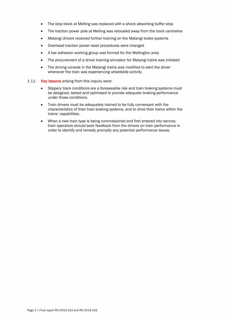
Figure 5
Melling 2 impact
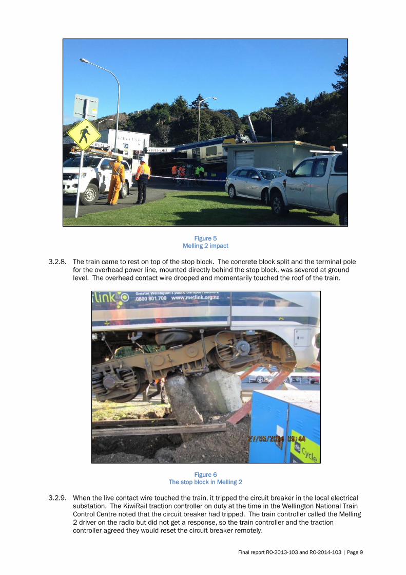
3.2.8. The train came to rest on top of the stop block. The concrete block split and the terminal pole
for the overhead power line, mounted directly behind the stop block, was severed at ground
level. The overhead contact wire drooped and momentarily touched the roof of the train.
Figure 6
The stop block in Melling 2
3.2.9. When the live contact wire touched the train, it tripped the circuit breaker in the local electrical
substation. The KiwiRail traction controller on duty at the time in the Wellington National Train
Control Centre noted that the circuit breaker had tripped. The train controller called the Melling
2 driver on the radio but did not get a response, so the train controller and the traction
controller agreed they would reset the circuit breaker remotely.

Page 10 | Final report RO-2013-103 and RO-2014-103
3.2.10. A KiwiRail employee, who had been waiting to board the train as a passenger, recognised the
potential electrical hazard to the public and prevented people on the platform touching the train
until the overhead wire had been made safe.
3.2.11. The train manager attended to the passengers, checked for injuries and performed first aid as
required. The driver went to the rear cab to use the radio to call train control. He reported the
accident, requested that the overhead power supply be made safe, and asked for emergency
services to attend.
3.2.12. Emergency services attended the scene and secured the train from public access. Ambulance
staff entered the train through the emergency door at the rear to attend to one passenger with
minor injuries and another in shock. The passenger doors remained closed for 22 minutes
after the accident, until the train was deemed safe for passengers to exit.
3.3. The drivers
3.3.1. At the time of the Melling 1 accident in 2013, the driver had 11 years’ driving experience with
the operator. He had converted from the Ganz Mavag type train to drive the newer Matangi
type train in 2011 and had been driving them regularly since. He was tested under the
operator’s standard policy for the presence of drugs and alcohol and found to be clear.
3.3.2. At the time of the Melling 2 accident in 2014 that driver had 11.5 years’ driving experience with
the operator. He had been driving the Matangi trains since they were introduced in 2011. After
the accident the driver was tested under the operator’s standard policy for the presence of
drugs and alcohol. He had a positive result for THC acid5 in his urine (further information on the
effects of cannabis is provided in Appendix 5).
3.4. Computer-controlled brake system
3.4.1. The Matangi brakes are controlled by computers (control units). The control units read a
driver’s brake demand signal and each activates an appropriate brake force depending on the
speed and weight of the train at the time (see Figure 7). The control units each respond
independently to the demand signal by calculating the required brake force. The control units
then check how much brake force can be achieved using dynamic brakes and back off an
equivalent friction brake force to ensure that dynamic is the preferred brake force.
Figure 7
Brake computer control system
5 THC acid = 11-nor-delta-9-tetrahydrocannabinol-9-carboxylic acid (or TCH-COOH).

Final report RO-2013-103 and RO-2014-103 | Page 11
3.4.2. As the train slows down, there is a point where dynamic braking cannot generate enough brake
force. At around 14 km/h the friction brakes are blended in and dynamic brakes faded out.
3.5. Rail adhesion
3.5.1. Adhesion, in rail terminology, refers to the degree of grip, or friction, between a train wheel tread
and the top surface of the rail head. Adhesion is the same as the friction coefficient but
expressed as a percentage. The normal range for adhesion on rail is between 12% and 40%
(see Appendix 4 for more information on adhesion).
3.5.2. Any brake application to a wheel will slow its rotating speed, which is transferred through the
contact patch6 between the wheel and the rail as a decelerating brake force. If the brake force
is greater than the maximum adhesion force possible in the conditions, the wheel will begin to
slide7. The effects of low adhesion upon a train are that the wheels may slide under braking
and stopping distances will be longer.
3.5.3. The Matangi procurement specification required the brake system designer to nominate the
minimum adhesion level that its equipment would need to achieve the specified deceleration
rates. The nominated levels were 9.6% adhesion for full service braking and 14.2% adhesion
for emergency braking.
3.5.4. Low adhesion as described in this report is when the adhesion is 10% or less. A subset of this
condition is that when the adhesion is under 5% it can be termed very low adhesion. Low
adhesion is an operational risk for train operators, while the very low adhesion condition is an
important consideration for equipment designers. Any change to the interface between the rail
and the wheel, such as the presence of water, leaves or grease, may affect the adhesion.
3.5.5. The most common cause of low adhesion is when a light layer of moisture forms or collects on
the top of the rail. This may be caused by morning dew, light rain or mist. When the moisture
combines with other contaminants normally found on a rail, such as dirt, rust, brake dust or
solid particles of air pollutants, it can form a slurry that acts as a lubricant. In heavy rain this
slurry tends to wash off the rail top and thus low adhesion becomes less of a problem.
3.6. Wheel-slide protection system
3.6.1. If a wheel starts to slide while a train is braking, its ability to apply an effective braking force
through the contact patch is reduced. However, a small amount of controlled wheel slide can
optimise the brake force. A wheel-slide protection8 system allows a braked train wheel to rotate
up to 20% slower than the train speed to achieve the most effective braking force in low-
adhesion conditions. However, the actual train speed is not usually measured by these
systems. Instead, it relies on a software-derived value analogous to the train speed called the
‘reference speed’. The system will override the brake force applied by the driver to keep the
wheel speed within the 20% band below the reference speed. The Matangi has two types of
wheel-slide protection system.
3.6.2. One wheel-slide protection system is a software application within another controller. It resides
in the two traction control units (see Figure 7) and is effective only when dynamic braking is in
use. The other wheel-slide protection system is a dedicated, stand-alone, computerised control
unit that only works with the pneumatic friction brakes. A system of this type is fitted to both
the motor and the trailer cars. It continuously monitors for wheel slide and operates whenever
wheel slide is detected while the friction brakes are in use. This wheel-slide protection system is
disabled when the train speed drops below 5 km/h.
6 The contact patch is the rolling contact area between a train wheel tread and the top surface of the rail
head. 7 Wheel slide is a condition where the rotational speed of a wheel is less than that corresponding to the
actual linear speed of the train. 8 Wheel-slide protection is a control system that limits any applied brake force during times of reduced
adhesion to utilise the maximum available adhesion and to prevent the wheels locking up. It is analogous to
anti-lock braking on a motor car.

Page 12 | Final report RO-2013-103 and RO-2014-103
3.7. Similar accidents
England
3.7.1. In 2005 the Rail Accident Investigation Branch in England investigated a series of low-adhesion-
related events that occurred in 2004 and 2005 (RAIB, 2005). The investigation identified two
key points that were relevant to New Zealand. One was that operators used past events to
predict low adhesion rather than just monitoring current conditions or risk. The second point
was that the train operating companies did not understand the characteristics of their new
trains. That lack of understanding led to inadequate briefing of drivers and suboptimal
performance of the wheel-slide protection systems.
3.7.2. The report also highlighted: a lack of industry knowledge on the cause of low adhesion; a lack of
test procedures to optimise the performance of whole-train braking systems with wheel-slide
protection; and that further research was required to find the optimum set-up parameters for
wheel-slide protection systems.
Melbourne, Australia
3.7.3. In Melbourne a series of incidents occurred in 2009 in which trains failed to brake effectively
and overran platforms. The Office of the Chief Investigator Transport Safety investigated
(OCITS, 2009) and found several contributory factors. The listed contributory factors were:
moisture on the rail caused low-adhesion conditions
the Nexas trains’ braking system response to a wheel-slide event
the Nexas trains did not have tread brakes, which could have otherwise helped
to clean the wheel tread surface and improved braking
the train’s very good dry-track braking performance may have raised drivers’
expectations in low-adhesion conditions
drivers did not have a sufficient depth of understanding of how the Nexas
braking system worked or specific guidance on operational procedures when
encountering low adhesion
the network risk management of low-adhesion conditions was inadequate at the
time
low-adhesion braking performance requirements were not adequately defined in
the procurement specifications nor verified in acceptance tests.
Queensland, Australia
3.7.4. In 2013 a Queensland Rail passenger train failed to stop at a platform and collided with the
end-of-line buffer stop. The train rode up over the buffer stop and onto the platform, where it
flattened the mast for the overhead power line and came to rest inside the station building. The
train had encountered low-adhesion conditions and the driver’s actions were not contributory.
The Australian Transport Safety Bureau’s report into the accident listed the main contributing
factor as the operator’s inadequate management of low-adhesion risk (ATSB, 2013).

Final report RO-2013-103 and RO-2014-103 | Page 13
4. Analysis
4.1. Introduction
4.1.1. Operating trains in conditions of low rail adhesion is a predictable risk applicable to any rail
system. The causes of low adhesion may vary from one country, region or town to the next, but
the effect is the same: braking in low-adhesion conditions will increase the distance required to
stop a train.
4.1.2. We know that low rail-adhesion conditions existed in both of the Melling accidents because
wheel-slide protection activities were recorded by the train data loggers. However, the exact
locations of any low-adhesion area(s), the extent of each area or areas, and the actual levels of
low adhesion present at the time were not able to be determined.
4.1.3. There was nothing in the condition of the train wheels or the profile of the rail that would have
adversely affected the wheel-to-rail contact patch.
4.1.4. The driver of the Melling 2 train tested positive for the presence of cannabis metabolites in his
urine. The investigation was unable to establish whether his performance on the day was
impaired by the effects of cannabis. However, the use of performance-impairing substances by
train drivers is a significant safety issue.
4.1.5. As the following analysis shows, a factor contributing to each accident was that the train
braking system did not perform as well as it could have in the low-adhesion conditions.
4.1.6. A key safety issue was that the National Rail System Standards (NRSS) did not require the
Matangi braking system to be tested under slippery track conditions against an appropriate
standard. Consequently the train brake system had not been optimised for low-adhesion
conditions.
4.1.7. The analysis discusses what happened in each case leading up to the collision.
4.1.8. Consideration is also given to: the performance of the train braking system; driver training in
respect of the differences between the Ganz Mavag and Matangi braking systems; and the
management of risk to trains operating into terminating stations, which had not kept pace with
industry changes.
4.2. Interpretation of evidence
Melling 1
4.2.1. The driver of the Melling 1 train had braked smoothly down to 47 km/h by the time his train
reached the start of the platform. This was below the maximum speed of 50 km/h. When he
increased the brake demand from 31% to 50% the wheels lost adhesion and began to slide.
The dynamic brakes in the motor car were the only brakes in use at the time and the traction
control units attempted to control the wheel slide. The train was about 52 m from the stop
block and it would travel that distance in about six seconds.
4.2.2. The driver applied full service brake, then full pneumatic brake9, followed by the emergency
brake. The computer-controlled brake system responded by disabling the dynamic brakes.
Then it increased the friction brake force on both the motor car and the trailer. As the friction
brake force increased, the wheels continued to slide. The applied brake force was limited by
the wheel-slide protection system while it attempted to optimise the train braking force. The
train braking system was unable to apply an effective brake force in the time available. The
train collided with the stop block at 0754 at an estimated speed of 25 km/h.
4.2.3. The speeds and brake actions are presented graphically in Appendix 1.
9 Applying full pneumatic brake is effectively applying emergency brake.

Page 14 | Final report RO-2013-103 and RO-2014-103
Melling 2
4.2.4. The Melling 2 driver started decelerating his train 1.2 kilometres from the Melling Station stop
block by selecting ‘off’ with the power/brake control lever. He increased the brake to 23% then
reduced it to 18% when the train was about 525 m from the stop block. At 430 m out from the
stop block, the wheels started to slide. The train was travelling at 58 km/h and the computer-
controlled braking system was using dynamic brakes only. The traction control units were
unable to control the wheel slide within three seconds, so the computer-controlled brake
system disabled the dynamic brakes and increased the friction brake force in the motor car.
4.2.5. The driver had also realised that the train was not slowing at the rate he expected, so he
increased brake demand to 50%, and then to 100%. The computer-controlled brake system
responded by increasing the friction brake force in the trailer car to about 75%, which caused
the trailer car wheels to slide also. Four seconds later the driver applied full pneumatic brake,
followed by emergency brake.
4.2.6. After the dynamic brakes were disabled, the wheel-slide protection units fluctuated the
friction brake force in both cars in an attempt to control the slide until the train hit the stop
block at an estimated speed of 35 km/h. The wheel-slide protection systems were unable to
regain an effective rate of deceleration over the last 430 m (see Appendix 1 for distances
and speeds).
4.2.7. The driver of the Melling 2 train tested positive for cannabis, which is of concern. The
Commission has included substance use on its ‘watch list’ and encourages regulators and
operators to put measures in place to prevent substance impairment by persons in safety-
critical roles. It was not possible to determine whether the driver was impaired at the time of
the accident.
4.2.8. Although cannabis impairment reduces with time since exposure it affects people differently
and is known to impair the executive cognitive function of information processing. Other
executive functions affected are planning, decision-making, risk taking, and working memory.
All of these functions are crucial for a train driver to operate safely (see Appendix 5 for more
details).
Conditions common to both accidents
4.2.9. Both drivers were handling their trains in a normal way. They approached Melling Station within
the speed limit for the line and they were on target to reduce the train speed to less than 50
km/h by the time they reached the start of the platform.
4.2.10. Both drivers said that they had been alert and focused upon the task and not distracted. They
had had light duty schedules with adequate periods of rest in the days leading up to their
respective accidents. Cell phone records proved that the drivers were not engaged in text or
voice communications at the time. Therefore, fatigue and distraction were very unlikely to have
been factors in either accident.
4.2.11. The train event recorders showed that the train wheel-slide protection system activated in both
accidents, meaning that low adhesion was a common factor.
4.2.12. Both trains were repaired sufficiently for the brakes to be tested on the track. Repairs were
limited to facilitate a safe test run but all brake equipment and brake-controller software were
kept as they originally were during the accidents. Test runs were conducted by KiwiRail
engineers on dry track around the Wellington rail network, with a Commission observer on
board. Several brake test runs from a steady speed to a full stop were also conducted using
various combinations of brake selection, pneumatic brake and emergency brake.
4.2.13. These test runs proved that the train brakes were working on both trains at the time of the
accidents, and that each train conformed to the NRSS standard for stopping distances on dry
track.

Final report RO-2013-103 and RO-2014-103 | Page 15
4.2.14. The Commission engaged MetService to analyse data on the weather conditions preceding both
accidents. They concluded that in both cases dew was likely to have formed on the track and
that the weather conditions preceding each accident had been dry for several days. These were
the ideal circumstances for low-adhesion conditions to exist.
4.2.15. Several dry days preceding the accidents would have allowed a layer of natural deposits to form
on the top of the rail, which was then followed by the formation of dew. The resulting mixture
would have created a low-adhesion layer between the rail and the train wheels.
4.3. Management of infrastructure risk at terminating stations
The line speed limit
4.3.1. The maximum line speed for approaching Melling Station was 70 km/h. Drivers were taught to
aim to have their train speeds at below 50 km/h by the time the trains reached the beginning of
the platform. The line speed is set depending on the geometry of the track. From a risk
perspective, Melling is a terminating station, meaning the consequences of overrunning the
platform are much higher than at non-terminating stations. The same applies to the target
speed for when the train reaches the start of the platform. Any train malfunction, low track
adhesion or underperformance of the train braking system risks the train colliding with the stop
block.
4.3.2. The Commission recommended that KiwiRail reassess the speed limit for trains approaching
Melling Station, and that it also reassess the speed limit for trains approaching other
terminating stations on the rail network. KiwiRail has since accepted these recommendations
and addressed the safety issue.
The stop block
4.3.3. The concrete stop block had been installed in 1954. It lacked the impact-absorbing qualities of
more modern stop blocks. The less effective they are, the greater the damage to the train and
its occupants, as both these collisions demonstrated. The Commission recommended that
KiwiRail replace the concrete stop block with a more appropriate shock-absorbing system
similar to the type being installed in Auckland at the time. KiwiRail accepted this
recommendation and replaced the stop block.
The overhead power
4.3.4. There were two issues with the overhead traction power system. Firstly, the terminal pole was
hit by the Melling 2 train because it was directly in the path of the train when it collided with and
overran the stop block. The force of the collision severed the pole, causing the live overhead
wire to droop and contact the train.
4.3.5. The Commission recommended that KiwiRail relocate the terminal pole out of line with a direct
overrun. This has since been completed with a new cantilevered pole mounted off to one side
of the rail centreline and the safety recommendation has been closed.
4.3.6. When the contact wire drooped and touched the train, it tripped the electrical protection
system, which led to the second issue. The traction controller at the Wellington National Train
Control Centre reset the power before the driver was able to warn train control of the accident.
The Commission raised with KiwiRail the risk of promptly resetting the overhead power without
first establishing the reason for the system tripping.
4.3.7. After two further incidents KiwiRail submitted to the Commission in December 2014 that it had
accepted its concerns about promptly resetting the overhead power after a protection trip.
KiwiRail then issued an internal memo to change its operating procedures. Based on this
action the Commission did not issue a safety recommendation.

Page 16 | Final report RO-2013-103 and RO-2014-103
4.4. Train brake performance
Brake performance expectations
4.4.1. Appendix 2 demonstrates the best theoretical stopping distance for a Matangi train in low-
adhesion conditions. It assumes that the wheel-slide protection systems operate perfectly to
control the wheel creep and allow the maximum brake effort to be applied in the conditions.
The calculation shows that a train with a typical passenger load for Melling could decelerate at
0.49 m/s2 to stop in 197 m from 50 km/h using full service brake in low-adhesion conditions
(at 5%).
4.4.2. In the Melling 2 accident (see details in Appendix 1) the train managed to decelerate at 0.3
m/s2 over the first 251 m, reducing to 0.015 m/s2 over the remaining 179 m, and only slow by
23 km/h but not stop in the total distance of 430 m. This comparison between theoretical and
actual brake performance indicated that either the adhesion was much less than 5% or there
was a performance issue with the train brakes in low-adhesion conditions, or that there was a
combination of both factors.
4.4.3. The train commissioning tests conducted by the manufacturer established that the train braking
system performed to the GWRC procurement specification. These tests included extensive test
runs with various combinations of brake application and some with simulated low-adhesion
conditions. The overall requirement was that the train complied with NRSS/6 – Engineering
Interoperability Standard, Version 1 (NRSS/6) to stop within 460 m from a speed of 100 km/h
in all normal climatic conditions. Testing proved that the train met the NRSS/6 stopping
distance requirements.
4.4.4. The commissioning test specification did not require the train braking and wheel-slide
protection systems to be tested in controlled low-adhesion conditions in accordance with an
internationally recognised standard10, nor was it required by any other authority.
4.4.5. To investigate the performance of the brake system, GWRC agreed to conduct a series of brake
tests in low-adhesion conditions and measure the performance of the Matangi brake system.
Low-adhesion brake test programme
4.4.6. The tests proved that in low-adhesion conditions the current configuration of the computer-
controlled brake system did not perform as well as it could have. Several opportunities for
improving the train brake performance were identified and trialled. These included:
10 For example, UIC 541-05.
Findings
1. It is very likely that for both collisions with the stop block at Melling Station, an extended
period of dry weather combined with the formation of dew on the rail resulted in a
condition of low rail adhesion along the approach to the station.
2. It was not possible to determine whether the driver of the Melling 2 train was impaired by
cannabis. However, the fact that he had cannabis in his system is a serious safety issue.
3. Both trains were travelling at a normal speed of approach to Melling Station and both
drivers applied a normal braking technique during the approach.
4. The operating risk and potential consequences of a train overrunning the platform at
Melling Station and colliding with the stop block had not been adequately considered. No
special speed restriction for the approach had been set; the stop block was an older and
less effective design than its modern equivalent; and the pole carrying the overhead
traction power line was placed directly behind the stop block where it was prone to
damage.
Final report RO-2013-103 and RO-2014-103 | Page 17
reducing the initial amount of available dynamic brake effort
reducing subsequent available dynamic brake effort after each wheel-slide control
attempt
improving the trailer car friction brake behaviour during wheel slide with dynamic brakes
optimising the wheel-slide control in the motor car
improving the handover between dynamic and friction brake controllers
improving the interaction of automatic brakes with the manual pneumatic brakes.
The system was reconfigured and further trials were conducted.
4.4.7. As a result of the test programme, GWRC initiated corrective actions to improve the low-
adhesion brake performance and approved software changes. The first software upgrade was
rolled out across the Matangi fleet in 2015.
4.4.8. The test programme raised a further concern that the wheel-slide protection system for the
friction brakes was not performing in accordance with the UIC 541-05 standard11. GWRC
arranged for the brake manufacturer to conduct a more rigorous test of the wheel-slide
protection units in a test facility in Italy. This resulted in a further software upgrade to improve
the performance of the friction brake wheel-slide protection system in low-adhesion conditions.
This software upgrade was rolled out across the fleet in mid-2016.
4.4.9. Following the testing programme and the software changes to the train brake system, the
Matangi train brake performance in low-adhesion conditions was noticeably improved.
4.4.10. However, there are too many variables, unknowns and possible scenarios to draw any definitive
conclusions on whether the trains would have stopped before the stop blocks if these
improvements had been made when the trains were commissioned. For example:
the dew suspected of causing the low adhesion evaporated soon after the events, so the
extent and level of low adhesion could not be measured
the method of measuring low adhesion is subject to variability and the result may differ
from the actual adhesion experienced by a train
the control inputs from the drivers could vary depending upon circumstances at the
time, such as: their choice of speed and brake selections; their knowledge about how
the brakes worked; and the response they had each experienced with the brakes during
the accidents.
New Zealand standards for train brakes
4.4.11. It is concerning that the brake performance of a new and modern commuter train was only
made to comply with the basic requirements of NRSS/6. The standard is silent on: low-
adhesion brake performance; wheel-slide prevention systems; full train brake performance
across different braking systems; and reference to appropriate international standards.
4.4.12. Although the selected train brake equipment had the capability to perform well in low-adhesion
conditions, the brake performance specifications did not require it to be verified. Therefore, the
system was not set up for optimum performance. The current trend in Europe is to test train
brakes to local standards12, with a complete train as a fully integrated brake system. These
standards include the verification of wheel-slide protection systems in controlled low-adhesion
conditions and the optimal integration of dynamic and friction brakes.
4.4.13. The NRSS was originally intended to provide an interoperability framework for rail participants
to meet when wishing to operate on the rail network. It is still the only formal set of rail
standards available in New Zealand.
11 UIC is the Ünion Internationale Des Chemins De Fer”(International Union of Railways) 12 For example in UK; BS EN 15595:2009 and RSSB GM/GN2695.

Page 18 | Final report RO-2013-103 and RO-2014-103
4.4.14. In 2010 the Commission issued three safety recommendations to the Secretary for Transport to
address safety issues relating to the status of the NRSS. As a result of the Melling accidents
the Commission issued a new recommendation to the NZ Transport Agency in 2015 to review
the NRSS to ensure that low-adhesion braking requirements were incorporated into the
standards and that they were applicable to all trains intended to operate on the National Rail
System. The Commission now has a total of seven open safety recommendations targeting
changes to the NRSS. Three are to the Secretary of Transport and four to the NZ Transport
Agency.
4.4.15. The NZ Transport Agency is currently addressing these recommendations by undertaking an
independent review to establish an appropriate rail regulatory framework for the future. In light
of this review the Commission makes no new recommendations on this safety issue.
4.5. Driver training
4.5.1. The Matangi driver conversion training suggested that drivers consider the computer-controlled
brake system as a ‘black box’ that performed better than the braking system in the older Ganz-
Mavag trains. This suggestion was reinforced to the drivers when they experienced the Matangi
train’s effective brakes on dry track.
4.5.2. Critical information describing how the computer-controlled brake system operated was not
provided in the conversion course material or in the Train Crew Manual. Several drivers were
interviewed about their understanding of how the computer-controlled braking system worked.
It became evident that the conversion training had not adequately informed drivers about the
differences between the two braking systems, particularly in low-adhesion conditions, and how
the brake effort is shared between the motor car and trailer.
4.5.3. A key difference was the Matangi’s preference for using dynamic brakes. This reduced the
number of braked wheels to just those wheels on the motor car and consequently it required a
higher level of adhesion to deliver that brake force. The effect was that the Matangi would
experience wheel slide more often than the Ganz-Mavag in low-adhesion conditions. (See
Appendix 3 for more details.)
4.5.4. Another key difference between these two train brake systems was how brake effort was shared
between the motor car and trailer. The Matangi computer-controlled brake system applied all
brake effort from the motor car before using the trailer car brakes. The Ganz-Mavag stepped
the brake effort sequentially in thirds. The first step would apply one-third brake force from the
motor car, the next step would add one-third to the trailer, the next would increase the motor
car to two-thirds and so on until full service brake had been reached on each car.
4.5.5. In a four-year period, drivers encountered various braking problems with the newly
commissioned trains, including dynamic brakes tripping out and their being unable to stop the
trains at target points. The problems sometimes resulted in platform overruns, which were
subsequently reported to the regulator and the operator but little progress was made in
resolving them. This led to drivers losing confidence in the braking system and to experiment
with alternative braking techniques or work-around actions.
4.5.6. The operator did not have a best practice of braking in an emergency, so had left it to the
drivers’ discretion. A benefit of the brake test programme was drivers actually experiencing
wheel-slide protection activity while braking on a safe and controlled low-adhesion test track.
The operator was subsequently able to define a best-practice braking technique for low-
adhesion conditions and retrain its drivers accordingly.
4.6. Subsequent events and preventive measures
4.6.1. On 10 June 2015 at 1039, a third Matangi train13 had a braking problem at Melling in low-
adhesion conditions. The Commission made enquiries into the incident and reviewed the train
13 Matangi train FP/FT 4218

Final report RO-2013-103 and RO-2014-103 | Page 19
data logger record. The train had been upgraded with the new brake control software and the
driver was aware of the new, best-practice, low-adhesion braking technique.
4.6.2. The train started to slide near the ‘on-tracking boards’ at the start of the straight into Melling
Station, but the driver recognised the wheel-slide protection activity and applied emergency
brakes. The train was reported to have come to a stop from 35 km/h in 205 m, which
represents a deceleration rate of approximately 0.23 m/s2. The point where it stopped was
before the platform, so the driver then crept the train forward to the desired target stop point,
where it was stopped normally.
4.6.3. GWRC arranged for the wheel-slide activity to be presented to the driver’s screen of the train
management system. This will help drivers to recognise when low-adhesion conditions exist
and to implement their defensive driving techniques.
4.6.4. GWRC took the initiative to organise a ‘Low-adhesion working group’ in the Wellington area. The
group has members from all aspects of the rail industry, including the train operator, network
manager and infrastructure owner. The working group’s purpose is to share information about
low-adhesion conditions and collaboratively take action to reduce its effect on operations in the
Wellington rail network.
4.6.5. In October 2016 GWRC started the purchasing process for a Matangi train simulator to assist
with future driver training. Depending on the fidelity of the simulator controls, it could provide a
means to better prepare drivers for handling low-adhesion conditions.
Findings
5. The Matangi braking and wheel-slide protection systems were not performing as well as
they could have because they had not been tested against an appropriate standard and
tuned for optimum braking in low-adhesion conditions before the trains were
commissioned to service.
6. It could not be established whether either collision would have been prevented had the
brake and wheel-slide protection systems been operating to their optimum in low-adhesion
conditions.
7. The National Rail System Standards do not adequately address the braking performance in
low-adhesion conditions of modern metropolitan passenger trains that are fitted with
computer-controlled brake and wheel-slide protection systems.
8. The training that drivers received for transitioning from the Ganz Mavag to the Matangi
train type did not provide them with sufficient information in respect of the design and
correct operation of the train brake and wheel-slide protection systems.

Page 20 | Final report RO-2013-103 and RO-2014-103
5. Findings
5.1. It is very likely that for both collisions with the stop block at Melling Station, an extended period
of dry weather combined with the formation of dew on the rail resulted in a condition of low rail
adhesion along the approach to the station.
5.2. It was not possible to determine whether the driver of the Melling 2 train was impaired by
cannabis. However, the fact that he had cannabis in his system is a serious safety issue.
5.3. Both trains were travelling at a normal speed of approach to Melling Station and both drivers
applied a normal braking technique during the approach.
5.4. The operating risk and potential consequences of a train overrunning the platform at Melling
Station and colliding with the stop block had not been adequately considered. No special speed
restriction for the approach had been set; the stop block was an older and less effective design
than its modern equivalent; and the pole carrying the overhead traction power line was placed
directly behind the stop block where it was prone to damage.
5.5. The Matangi braking and wheel-slide protection systems were not performing as well as they
could have because they had not been tested against an appropriate standard and tuned for
optimum braking in low-adhesion conditions before the trains were commissioned to service.
5.6. It could not be established whether either collision would have been prevented had the brake
and wheel-slide protection systems been operating to their optimum in low-adhesion conditions.
5.7. The National Rail System Standards do not adequately address the braking performance in low-
adhesion conditions of modern metropolitan passenger trains that are fitted with computer-
controlled brake and wheel-slide protection systems.
5.8. The training that drivers received for transitioning from the Ganz Mavag to the Matangi train
type did not provide them with sufficient information in respect of the design and correct
operation of the train brake and wheel-slide protection systems.

Final report RO-2013-103 and RO-2014-103 | Page 21
6. Safety actions
6.1. General
6.1.1. The Commission classifies safety actions by two types:
(a) safety actions taken by the regulator or an operator to address safety issues identified
by the Commission during an inquiry that would otherwise result in the Commission
issuing a recommendation
(b) safety actions taken by the regulator or an operator to address other safety issues that
would not normally result in the Commission issuing a recommendation.
6.2. Safety actions addressing safety issues identified during an inquiry
6.2.1. GWRC conducted full train brake tests in sustained low-adhesion conditions then followed up
with corrective actions. This resulted in the upgrade of the computer-controlled brake system to
ensure that trains would stop in the shortest possible distance in low-adhesion conditions. The
software upgrades were rolled out across the fleet during a long weekend in early 2015. This
included an indicator to drivers when wheel-slide protection activity was taking place. Further
upgrades to the wheel-slide protection systems were completed mid-2016.
6.2.2. KiwiRail retrained the Wellington metro train drivers to better inform them about how the
Matangi computer-controlled brakes worked and provided a best-practice braking technique in
low-adhesion conditions. All drivers went through a retraining module before the new software
was rolled out.
6.2.3. KiwiRail changed the network control operating procedures to ensure that whenever the
overhead power to a rail line tripped out the controllers would not reset the power before a
thorough and reasonable check to ensure that any trains in the area would not be put at undue
risk of electric shock.
6.2.4. GWRC set up and organised a cross-organisation ‘Low adhesion working group’ for the
Wellington area, which representatives from the owner, train maintenance, train operator,
networks owner and train control attend. The group meets regularly to focus jointly on
mitigating the risks of operating trains in low-adhesion conditions around the Wellington
network and to share information that is of use to the group.
6.2.5. GWRC has approved the procurement of a driver simulator for the Matangi to commence in
October 2016.
6.3. Safety actions addressing other safety issues
6.3.1. None identified

Page 22 | Final report RO-2013-103 and RO-2014-103
7. Recommendations
7.1. General
7.1.1. The Commission may issue, or give notice of, recommendations to any person or organisation
that it considers the most appropriate to address the identified safety issues, depending on
whether these safety issues are applicable to a single operator only or to the wider transport
sector. In this case, recommendations have been issued to KiwiRail and the NZ Transport
Agency. Notice of the recommendations to the NZ Transport Agency was also given to CAF New
Zealand Limited, Auckland Transport and Transdev Auckland.
7.1.2. In the interests of transport safety, it is important that these recommendations are
implemented without delay to help prevent similar accidents or incidents occurring in the future.
7.2. Recommendations to KiwiRail
Speed restrictions for terminal stations
7.2.1. Two trains have collided with the stop block at Melling Station in the space of just over one year.
The normal line speed for the section of track between the preceding station and Melling is 70
km/h. The Melling Station platform only becomes clearly visible to a train driver once their train
has rounded the last bend, about 400 m from the stop block. If trains were restricted to a lower
speed before they rounded the last bend, the risk of a platform overrun and resulting collision
with the stop block would be reduced.
7.2.2. On 30 June 2014 the Commission recommended that KiwiRail apply a suitable permanent
speed restriction to the last section of the Melling Line to reduce the approach speed to Melling
Station. (018/14)
7.2.3. On 8 July 2014 the General Manager – Rail Passenger Group advised that KiwiRail had reduced
the ‘line speed’ on the Melling Line from 70 km/h to 50 km/h and imposed a speed restriction
of 25 km/h for the approach to Melling Station.
7.2.4. On 26 March 2015 the Commission approved the closure of the recommendation on the basis
that the actions taken by KiwiRail had addressed the safety issue.
7.2.5. On 30 June 2014 the Commission recommended that KiwiRail assess all other terminating
stations on the controlled network throughout New Zealand and similarly apply permanent
speed restrictions as necessary to the approaches at those stations. (019/14)
7.2.6. On 8 July 2014 the General Manager – Rail Passenger Group advised that KiwiRail had:
Completed a risk assessment for all lines in the metro Wellington region that
have no over-run (end of line) with stop blocks to establish that the controls in
place are appropriate for managing approach speeds and distances to the stop
blocks in the event that there is a similar [occurrence] caused by lack of braking
action, and that any resultant impact damage would be adequately contained.
As a result of the risk assessment, “a 25 km/h speed restriction has been placed
on the Johnsonville Line, similar to that which has been introduced for the
Melling Line”.
7.2.7. On 23 September 2015 the Commission approved the closure of the recommendation on the
basis that the actions taken by KiwiRail had addressed the safety issue.
Stop block
7.2.8. The stop block installed at Melling was a solid concrete block with a limited ability to absorb
impact forces. It was physically shifted in the first collision, and even further in the second. The
second impact also split the concrete block near ground level and allowed it to rotate backward
under the train. The train rode up and over the stop block as a consequence, sustaining
substantial damage.

Final report RO-2013-103 and RO-2014-103 | Page 23
7.2.9. Modern shock-absorbing stop blocks used on other terminating train stations on the controlled
network reduce the consequences in terms of injury to persons and damage to trains if
overruns should occur that lead to trains striking the stop blocks.
7.2.10. On 30 June 2014 the Commission recommended that KiwiRail replace the type of stop block
that was in use at Melling with a new shock-absorbing type design that would be matched to the
likely impact forces from a Matangi train. (020/14)
7.2.11. On 21 July 2014 the General Manager – Rail Passenger Group replied:
KiwiRail advises its engineering team is currently in the design phase for the
replacement stop block. It is most likely the replacement will be of the “friction
retarder” type as used at Britomart Transport Centre, Manukau Station and
Onehunga Station. Key design inputs are the train loading, design impact speed
and available retarding track length (which could impact on the usable platform
length). A similar analysis is being undertaken on the Johnsonville Line buffer
stop.
7.2.12. On 23 June 2016 the Commission approved the closure of the recommendation on the basis
that the actions taken by KiwiRail had addressed the safety issue.
The overhead traction terminal pole
7.2.13. The stop block at Melling was mounted directly in front of the terminal (last) pole supporting the
high-voltage overhead contact wire for the electric trains. At the collision in 2013 the support
structure was damaged, and in the 2014 event the pole was snapped off at ground level,
causing the overhead contact wire to droop onto the body of the train. The fallen high-voltage
line created a risk to the train occupants and delayed the evacuation of the train after it came
to rest.
7.2.14. Placing the power pole directly in line with the stop block was a safety issue that increased the
potential consequences of a train overrunning the station platform and striking the stop block.
7.2.15. On 30 June 2014 the Commission recommended that KiwiRail relocate the terminal pole for
the overhead line at Melling Station to be clear of the potential train overrun path. (021/14)
7.2.16. On 21 July 2014 the General Manager – Rail Passenger Group replied:
KiwiRail advised that as part of the “friction retarder” type buffer solution being
implemented in response to recommendation 020/14, a design for an offset
pull-off pole is being prepared. This will remove the terminal pole from track
centre and relocate to a location where it would not be foul of a railed train. It is
expected that his design will also be considered for the terminal pole at
Johnsonville Station.
7.2.17. On 16 December 2015 the Commission approved the closure of the recommendation on the
basis that the actions taken by KiwiRail had addressed the safety issue.

Page 24 | Final report RO-2013-103 and RO-2014-103
7.3. Recommendations to NZ Transport Agency
Rail standards for new trains
7.3.1. The National Rail System Standard 6 – Engineering and Interoperability (NRSS/6) is the only
standard within the National Rail System set that defines braking performance. However, it
does not address the performance in low-adhesion conditions of modern metropolitan
passenger trains that are fitted with computer-controlled brake and wheel-slide protection
systems. The current NRSS/6 does not require any more from a braking system than that a
train is able to stop within a specified distance in normal climatic conditions and with a
maximum adhesion of 12%.
7.3.2. The regulator for the country of operation or the owner may define what adhesion conditions
might be encountered on a rail network and what level of braking performance is expected from
a new train and what standards the train is to be tested to for compliance. This is also the stage
in commissioning a new train when the interactions between all of the brake systems are
adjusted to achieve the optimum overall brake performance. The Rail Safety and Standards
Board in the UK has produced a guidance note (GM/GN2695) to achieve this purpose in the UK
but nothing similar exists for New Zealand.
7.3.3. The Matangi train brake systems were tested for compliance and proper operation, but they
were not tested and adjusted for optimum brake performance in low-adhesion conditions. The
Commission considers that the occurrences in Wellington may be repeated unless the NRSS is
revised.
7.3.4. As a minimum the Commission considers that the NRSS should call upon appropriate
international standards to formalise new train type testing and ensure that train braking
systems are tested in low-adhesion conditions and optimised for the trains.
7.3.5. On 26 March 2015 the Commission recommended that the Chief Executive of the NZ Transport
Agency require a full review of the NRSS, and in particular NRSS/6, to ensure that low-adhesion
braking requirements are defined in the standards and made applicable for all trains intended
to operate on the National Rail System. (005/15)
7.3.6. On 11 May 2015 the Chief Executive of the NZ Transport Agency responded:
While the Transport Agency cannot ‘require’ a full review of the National Rail
System Standards (NRSS), it is the Transport Agency’s intention to work with the
NRSS executive to ensure relevant aspects of low adhesion braking capability are
reflected in the appropriate standard.
Auckland trains
7.3.7. The Commission is aware that new passenger trains have recently been introduced in Auckland.
The Commission is not aware of any safety issues with the new trains, but expects that they
would have been tested to comply with the same National Rail System standards as the
Matangi trains in Wellington. Therefore, they may be exposed to the same lack of optimised
brake performance risks in low-adhesion conditions.
7.3.8. On 26 March 2015 the Commission recommended that the Chief Executive of the New Zealand
Transport Agency review the process followed for the commissioning of the Auckland trains, and
if they have not been optimised for low adhesion conditions or adhesion management systems
introduced to reduce the risk of incidents across the network, he address those safety issues in
line with the safety actions planned for the Matangi train operation (006/15)
7.3.9. On 11 May 2015 the Chief Executive of the NZ Transport Agency responded:
The Transport Agency has commenced discussions with Auckland Transport and
CAF regarding this recommendation.

Final report RO-2013-103 and RO-2014-103 | Page 25
7.3.10. On 9 April 2015 the Commission gave notice of preliminary safety recommendations 005/15
and 006/15 under section 9 of the Transport Accident Investigation Commission Act 1990 to
the following parties:
the Depot General Manager, CAF New Zealand Limited as the manufacturer and maintainer
of the new Auckland trains
the Chief Executive Officer of Auckland Transport as the owner of the new Auckland trains
the Managing Director of Transdev Auckland as the operator of the new Auckland trains.

Page 26 | Final report RO-2013-103 and RO-2014-103
8. Key lessons
8.1 Slippery track conditions are a foreseeable risk and train braking systems must be designed,
tested and optimised to provide adequate braking performance under those conditions.
8.2 Train drivers must be adequately trained to be fully conversant with the characteristics of their
train braking systems, and to drive their trains within the trains’ capabilities.
8.3 When a new train type is being commissioned and first entered into service, train operators
should seek feedback from the drivers on train performance in order to identify and remedy
promptly any potential performance issues.

Final report RO-2013-103 and RO-2014-103 | Page 27
9. Citations
Ashton, H. C. (2001). Pharmacology and effects of cannabis: a brief review. British Journal of Psychiatry,
178: 101-106.
ATSB. (2013). Collision of passenger train T842 with station platform, report RO-2013-005. Canberra:
Australian Transport Safety Bureau.
Crean et al, R. D. (2011). An evidence based review of acute and long-term effects of cannabis on
executive cognitive functions. J Addict Med, 5(1): 1-8. doi:10.1097/ADM:0b013e31820c23fa.
Huestis, M. A. (2007). Human cannabinoid pharmacokinetics. Chem Biodivers, 4(8): 1770-1804,
doi:10.1002/cbdv.200790152.
OCITS. (2009). Platform overruns, Siemans Nexas EMU, Connex/Metro Trains Melbourne. Melbourne:
Office of the Chief Investigator Transport Safety.
Olofsson, U., & Lewis, R. (2006). Tribology of the wheel-rail contact. In D. o. Railway Group KTH.
Stockholm, Sweden: Taylor and Francis Group, LLC.
RAIB. (2005). Autumn adhesion investigation part 3: Review of adhesion-related incidents, Autumn
2005. Derby: Rail Accident Investigation Branch, Department for Transport, UK.
RSSB. (2004). Review of Low Adhesion Research. Rail Safety Standards Board.
TCRP. (1997, May). Improved methods for increasing wheel/rail adhesion in the presence of natural
contaminatiion. Research Results Digest, Number 17.
Zhu, Y. (2013). Adhesion in the wheel-rail contact. Stockholm: Doctoral Thesis, Department of Machine
Design, Royal Institute of Technology.

Page 28 | Final report RO-2013-103 and RO-2014-103
Appendix 1: Distances and speeds

Final report RO-2013-103 and RO-2014-103 | Page 29
Appendix 2: Brake calculations

Page 30 | Final report RO-2013-103 and RO-2014-103
Appendix 3: Required coefficient of friction
Example of Matangi deceleration using the information and diagram in Appendix 2
Full train braking
If the brake force is to be applied evenly across all wheels.
The Normal force for the train is the force that acts vertically downwards on the train mass as a result of
gravity and is represented as: Fn = ma
Fn = (34 t + 41.5 t) x 9.81 m/s2 = 760.6 kN
Therefore the normal force per wheel: = Fn/(8 x 2) = 46.3 kN
Assume that all wheels are braked evenly and total required decelerating force is 68 kN
Therefore the required brake force (Fa) per braked wheel is 68 kN/(8 x2) = 4.25 kN
As the friction coefficient 𝜇 = 𝐹𝑎
𝐹𝑛, the minimum required friction coefficient needed to apply this braking
force without causing wheel slide is:
4.25/46.3 = 0.091 = 9%
Motor car braking only
If all braking must be provided by the motor car, the required deceleration force to slow the train
remains the same but it must be applied through fewer wheels, so the minimum required friction
coefficient will increase.
The motor car normal force: = 41.5 t x 9.81 m/s2 = 407 kN
Therefore the normal force per wheel: = 407 kN/(4 x 2) = 50.9 kN
The required brake force to stop the train is the same but it is shared across fewer wheels. The brake
force per wheel: = 68 kN/(4 x 2) = 8.5 kN
The minimum required friction coefficient is now:
8.5/50.9 = 0.16 = 16%
Conclusion
When the computer-controlled brake system applies only dynamic brakes to slow the train, a greater
level of adhesion is required to achieve the selected deceleration rate than would be required if the
brake effort were spread across the motor car and trailer car.
If this minimum required adhesion is not available, the motor car wheels will start to slide.

Final report RO-2013-103 and RO-2014-103 | Page 31
Appendix 4: Research on rail adhesion
A.1 The rolling contact surface area between the wheel tread and the top of the rail head plays a
critical part in the operation of all railway systems. This contact area is called the ‘contact
patch’. If the friction of this contact patch is too low, the wheels will lose adhesion and slip
when the train accelerates or slide when it brakes.
A.2 The rolling contact patch is oval shaped and typically about 100 square millimetres in area. For
a driven or braked wheel it consists of two regions called the ‘stick’ and the ‘slide’ regions
(Olofsson & Lewis, 2006). These regions vary depending on the applied traction or braking
force. When a train is coasting, with no power or braking, the whole contact patch area is
‘stick’. When brake force is applied the surface speed of the wheel moves slightly slower than
the speed at which the train is moving over the rail. This rolling friction causes the stick region
of the contact patch to reduce with a consequential increase in the slide region.
Figure 8
Rail-to-wheel contact
(Zhu, 2013)
slide stick
the stick region
reduces towards zero
area
Figure 9
Contact patch
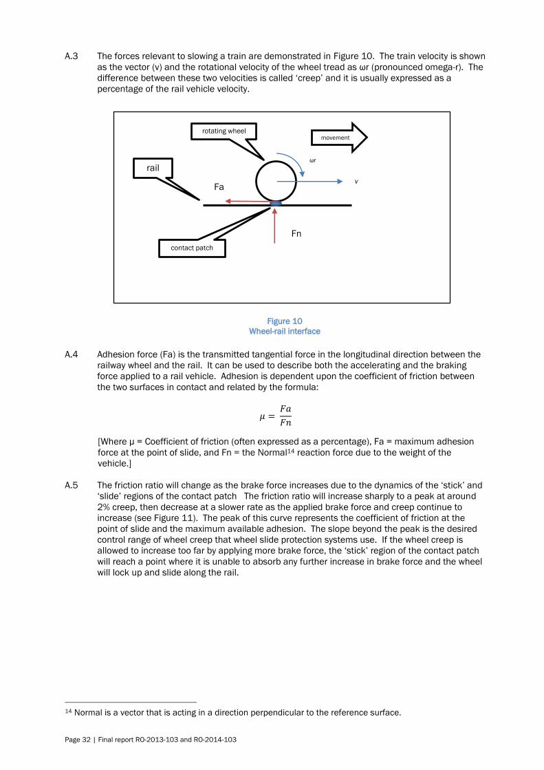
Page 32 | Final report RO-2013-103 and RO-2014-103
A.3 The forces relevant to slowing a train are demonstrated in Figure 10. The train velocity is shown
as the vector (v) and the rotational velocity of the wheel tread as ωr (pronounced omega-r). The
difference between these two velocities is called ‘creep’ and it is usually expressed as a
percentage of the rail vehicle velocity.
A.4 Adhesion force (Fa) is the transmitted tangential force in the longitudinal direction between the
railway wheel and the rail. It can be used to describe both the accelerating and the braking
force applied to a rail vehicle. Adhesion is dependent upon the coefficient of friction between
the two surfaces in contact and related by the formula:
𝜇 = 𝐹𝑎
𝐹𝑛
[Where µ = Coefficient of friction (often expressed as a percentage), Fa = maximum adhesion
force at the point of slide, and Fn = the Normal14 reaction force due to the weight of the
vehicle.]
A.5 The friction ratio will change as the brake force increases due to the dynamics of the ‘stick’ and
‘slide’ regions of the contact patch The friction ratio will increase sharply to a peak at around
2% creep, then decrease at a slower rate as the applied brake force and creep continue to
increase (see Figure 11). The peak of this curve represents the coefficient of friction at the
point of slide and the maximum available adhesion. The slope beyond the peak is the desired
control range of wheel creep that wheel slide protection systems use. If the wheel creep is
allowed to increase too far by applying more brake force, the ‘stick’ region of the contact patch
will reach a point where it is unable to absorb any further increase in brake force and the wheel
will lock up and slide along the rail.
14 Normal is a vector that is acting in a direction perpendicular to the reference surface.
Fn
Fa
rail
rotating wheel
contact patch
movement
ωr
v
Figure 10
Wheel-rail interface

Final report RO-2013-103 and RO-2014-103 | Page 33
Low adhesion
A.6 The coefficient of friction between a rail vehicle’s wheel tread and a dry rail is normally between
12% and 40%. Low adhesion is defined as when the coefficient of friction is at 10% or less.
Very low adhesion is a subset of low adhesion when the adhesion level is less than 5%. When
the interface is contaminated by a third body the coefficient of friction may change for the better
or worse. Often rail operators inject sand into the contact patch area to increase adhesion or
natural contaminants may collect on the rail head that reduce adhesion.
A.7 A North American research project conducted by the Transit Cooperative Research Program
found that low-adhesion conditions occurred in light drizzle, in the early mornings and on icy,
frosty rails. The research survey of 24 light rail and commuter rail transit agencies in North
America was intended to gain a better understanding of the wheel-to-rail adhesion in the
presence of natural contaminants. The results are summarised in its digest (TCRP, 1997).
Figure 12
Contamination of the wheel-rail interface
Figure 11
Adhesion related to slide
(Referred to as creep in this graph from Zhu, 2013)

Page 34 | Final report RO-2013-103 and RO-2014-103
A.8 A chemical analysis of rail head contaminants conducted by British Rail and the Association of
American Railroads showed that the rail head is normally covered with a thin film of active oils,
grease and solid debris. It found that the oils contained large organic molecules, acid ester,
ketone, amines and sulphur-containing compounds. The solid debris was oxides of iron and
other locally found components such as dirt and brake dust. These combined to form a surface
film that could not be removed chemically or by scrubbing. With the addition of small amounts
of water the film formed a slurry or paste that reduced adhesion. The research project
concluded that “moisture, even in small amounts, on the surface of the rail is the single most
important contaminant responsible for low adhesion”.
A.9 Beagley et al (cited in Zhu, 2013) published several papers in the Wear journal in 1975 that
described research into adhesion between the wheel-rail contact and the effects of
contaminants of water, oil and wear debris. Beagley found that a small amount of water mixed
with substantial quantities of debris could form a paste that significantly reduced adhesion. The
paste was squeezed aside if the water was sufficient. Zhu’s research also confirmed findings by
several other researchers cited in his thesis, that relative humidity (RH) influenced the friction
coefficient up to 55-65% RH but made no further change above that level of humidity. This was
associated with water molecules forming a boundary lubrication film around the natural
contaminants on the rail head.
A.10 The Rail Safety and Standards Board in the UK carried out a review of available research into
low adhesion in 2004. It found that low adhesion could not be attributed to a single cause, but
the most widespread effect noted was that of dew or newly falling rain on rails covered in tiny
particles of oil or debris. On a visibly rusty rail the film formed by the rust debris and water
molecules can support the wheel completely, and extremely low adhesion can result. With more
consistent rainfall, the viscosity of the film is so low that it is readily squeezed aside, returning
the adhesion to a higher level (RSSB, 2004).

Final report RO-2013-103 and RO-2014-103 | Page 35
Appendix 5: Research on cannabis impairment
A.1 There are several paths for a person to ingest cannabis, with variable concentrations of dosage
that, when combined with the variations in the human body shape, size and internal efficiency,
result in a range of reactions.
A.2 Once absorbed into the body, the THC15 and other cannabinoids are rapidly distributed to all
other tissues at rates dependent on the blood flow. Because they are extremely lipid soluble,
cannabinoids accumulate in the fatty tissues, reaching peak concentrations in four or five days.
After ingestion cannabinoids are metabolised in the liver then slowly released back into the
body compartments, including the brain. More than 20 metabolites are known, of which some
are psychoactive and one (11-hydroxy-THC) may be more potent than THC. Metabolites are
partly excreted in the urine but mainly into the gut, where they are reabsorbed, further
prolonging their actions. Consequently, there is a very poor relationship between the plasma or
urine concentration and the degree of cannabinoid-induced intoxication (Ashton, 2001).
A.3 The detection of cannabinoids in urine is indicative of prior cannabis exposure, but the long
excretion half-life of cannabis acid in the body, especially in chronic users, makes it difficult to
predict the timing of past drug use. A positive urine test does not provide information on the
route of administration, the amount of drug exposure, when drug exposure occurred, or the
degree of impairment (Huestis, 2007).
A.4 A 2011 literature review of research into the effects of cannabis use on the executive cognitive
functions found that it impaired information processing, which is a building block for attention
and concentration. Other executive functions affected were planning, decision-making, risk
taking, inhibition, impulsivity and working memory. The review found that recently abstinent
users (7 hours to 20 days) may or may not continue to experience impairment of attention,
concentration, inhibition and impulsivity during the interval associated with the elimination of
THC and its metabolites from the brain. Decision-making and risk-taking capabilities had not
been thoroughly studied at the time but one study cited in the review suggested that these
abilities were also impaired for an extended period after exposure (Crean et al, 2011).
15 THC = delta-9-Tetrahydrocannabinol.


Recent railway occurrence reports published by
the Transport Accident Investigation Commission
(most recent at top of list)
RO-2015-101 Pedestrian fatality, Morningside Drive pedestrian level crossing, West Auckland,
29 January 2015
RO-2014-101 Collision between heavy road vehicle and the Northern Explorer passenger train,
Te Onetea Road level crossing, Rangiriri, 27 February 2014
RO-2012-103 Derailment of freight Train 229, Rangitawa-Maewa, North Island Main Trunk,
3 May 2012
RO-2012-105 Unsafe recovery from wrong-route, at Wiri Junction, 31 August 2012
RO-2013-107 Express freight MP16 derailment, Mercer, North Island Main Trunk,
3 September 2013
RO-2012-104 Overran limit of track warrant, Parikawa, Main North line, 1 August 2012
RO-2013-104 Derailment of metro passenger Train 8219 , Wellington, 20 May 2013
Urgent
Recommendations
RO-2015-101
Pedestrian fatality, Morningside Drive level crossing, West Auckland, 29 January
2015
RO-2013-105 Capital Connection passenger train, departed Waikanae Station with mobility
hoist deployed 10 June 2013
RO-2014-102 High-speed roll-over, empty passenger Train 5153, Westfield, South Auckland,
2 March 2014
RO-2013-106 Track occupation irregularity, leading to near head-on collision, Otira-Arthur’s
Pass, 10 June 2013
RO-2012-102 Train control power failure, 26 April 2012
Interim Report
RO-2014-103
Metropolitan passenger train, collision with stop block, Melling Station,
Wellington, 27 May 2014
RO-2013-108 Near collision between 2 metro passenger trains, Wellington, 9 September 2013
11-106 Hi-rail vehicle nearly struck by passenger train, Crown Road level crossing near
Paerata, North Island Main Trunk, 28 November 2011
11-102 Track occupation irregularity, leading to near head-on collision, Staircase-
Craigieburn, 13 April 2011

Price $18.00 ISSN 1178-4164 (Print)
ISSN 1179-9102 (Online)