Embed Size (px)
Citation preview
Final Report
AHRI Report No. 8014
EFFECTS OF LOW RETURN AIR TEMPERATURE ON GAS FIRED FORCED
AIR FURNACES
Final Report
April 2017
Rick Sandstrom, Nicholas Hughes, CJ Suchovsky and Carl Suchovsky
GAS CONSULTANTS, INC.
Walton Hills, Ohio
Prepared for
AIR-CONDITIONING, HEATING AND REFRIGERATION INSTITUTE
2111 Wilson Boulevard, Suite 500, Arlington, Virginia 22201-3001
© 2017 AHRI
DISCLAIMER
This report was prepared as an account of work sponsored by the Air-Conditioning, Heating, and
Refrigeration Institute (AHRI). Neither AHRI, its research program financial supporters, or any
agency thereof, nor any of their employees, contractors, subcontractors or employees thereof -
makes any warranty, expressed or implied; assumes any legal liability or responsibility for the
accuracy, completeness, any third party’s use of, or the results of such use of any information,
apparatus, product, or process disclosed in this report; or represents that its use would not
infringe privately owned rights. Reference herein to any specific commercial product, process,
or service by trade name, trademark, manufacturer, or otherwise, does not necessarily constitute
nor imply its endorsement, recommendation, or favoring by AHRI, its sponsors, or any agency
thereof or their contractors or subcontractors. The views and opinions of authors expressed
herein do not necessarily state or reflect those of AHRI, its program sponsors, or any agency
thereof.

Gas Gas Consultants, Inc.
Final Report-AHRI Project 8014 Effects of Low Return Air Temperature on Gas Fired Forced Air Furnaces Page 2 of 70
TABLE OF CONTENTS
History/Background ....................................................................................................................................................... 3
Executive Summary ....................................................................................................................................................... 6
Furnace Specifications .............................................................................................................................................. 7
Baseline and Post Test CO air free data ..................................................................................................................... 7
Conclusion ..................................................................................................................................................................... 9
Basic Evaluation Process .............................................................................................................................................. 10
Initial Setup and Baseline Data for Furnace Samples 1 thru 5 ..................................................................................... 11
Baseline Data Prior To Corrosion Cycling ................................................................................................................. 11
Preliminary Heat Exchanger Temperature Evaluation ............................................................................................ 13
Preliminary Evaluation ............................................................................................................................................. 15
Flow Rates for spiking gas ........................................................................................................................................ 16
Test Structure for maintaing return air temperature .................................................................................................. 17
Post Corrosion Cycling Results ..................................................................................................................................... 23
Furnace 1 ................................................................................................................................................................. 23
Furnace 2 ................................................................................................................................................................ 24
Furnace 3 ............................................................................................................................................................... 24
Furnace 4 ............................................................................................................................................................... 25
Furnace 5 .............................................................................................................................................................. 25
Test Equipment and Labatory Procedures .................................................................................................................. 29
Appendix ……………………………………………………………………………………………………………………………………………………………….30
Photos of Setup…………………………………………………………………………………………………………………………………………………31
Photos of Post Cycle Furnaces …………………………………………………………………………………………………………………………35
Power Point Of Heat Exchanger Cold Temps ……………………………………………………………………………………………………57
Gas Gas Consultants, Inc.
Final Report-AHRI Project 8014 Effects of Low Return Air Temperature on Gas Fired Forced Air Furnaces Page 3 of 70
HISTORY/BACKGROUND
The gas fired furnace manufacturers had expressed concerns about life expectancy of their
products when the return air to the furnace was below the normally expected household air
temperature of 70⁰F. It has been long known that when persons leave on vacation they very
often set their comfort thermostat down to a much lower temperature than 70⁰F to conserve
energy/reduce heating bills. Those temperatures are dependent upon the brand of comfort
thermostat they own, but temperature settings to 45 ⁰F are possible with many brands.
At reduced air temperatures in the house and while the occupants are on vacation the return
air will be passed over the leading sections of the heat exchanger and cool the flue gas lower
than if the return air temperature were at 70⁰F. With “colder” return air temperatures the
concern was that the condition would accelerate the formation of condensate in the heat
exchanger which in turn might accelerate the formation of corrosion in the heat exchanger.
Additionally, the concerns was that the formation of the condensate in high efficiency furnaces
may start to form “earlier” in the pathway of the heat exchanger, i.e. , before the secondary
heat exchanger, and form liquid in those portions of the heat exchanger which were not
intended to handle combustion condensate.
Since this report is being prepared for the AHRI members it is not necessary that a prolonged
discussion of how flue gas condensate forms in a heat exchanger is needed, but a few words
have been added without all the technical detail that would be necessary for the layman.
Corrosion had been one of the two leading causes of premature failure of the heat exchanger in
the past. The other cause being heat related stress which is currently addressed in Section 2.36,
Heating Element Cycling Test.
Two forms of acid formation may occur in gas furnaces:
The odorant added to natural and LP gas is a sulfur based compound and combines with
the moisture of combustion. Hence, if the moisture of the combustion process
condenses in the heat exchanger, sulfuric acid is formed.
The use of chlorine and fluorine compounds in cleaning solutions and spray aerosol
propellants was found to be a leading contributor to the corrosion of conventional heat
exchangers prior to the advent of condensing or high efficiency furnaces. These
compounds, when passed through a flame and combined with the moisture of
combustion can form hydrochloric and hydrofluoric acid.

Gas Gas Consultants, Inc.
Final Report-AHRI Project 8014 Effects of Low Return Air Temperature on Gas Fired Forced Air Furnaces Page 4 of 70
Improperly designed or adjusted low efficiency furnaces (non-condensing) can also end up with
acid condensate in the heat exchanger. High efficiency furnaces by their very nature have
condensate in the heat exchanger and must be designed with materials resistant to acid attack
in those portions of the heat exchanger where the condensate will form (specifically in the
secondary heat exchanger).
To address all the possible sources of acid attack on both low and high efficiency furnaces, the
gas furnace industry addressed the issue by the implementation of an accelerated corrosion life
test. The general approach used to accelerate the corrosion beings:
The first step is to shorten the operational “On” cycle, combine it with a long off cycle
and keep the circulating room air blower in continuous operation throughout the entire
On/Off cycle time.
This process causes an environment favorable to allowing condensate to form inside the
heat exchanger and flue gas passageways.
The second step for accelerating the test is accomplished by “spiking” the fuel gas with
hydrofluoro/chlora-carbons, thereby, increasing the acidity of the normal flue gases
found in North America.
This test process gave the industry/manufacturer a design tool for predicting the effects of flue
gas corrosion on their heat exchanger design.
The accelerated corrosion test is 800 hours of burner “On” time over 100 days of operation.
The test is conducted at normal household ambient air temperatures (nominally 70⁰F) and uses
a 4 minutes on and 8 minutes off burner cycle with the furnace circulating blower in operation
continuously to accelerate the cooling of the heat exchanger. The spiking gas concentration of
chlorine compounds is predicated on either using indoor air for the combustion process or
using outdoor air. Indoor air has been shown to contain more compounds such as household
cleaners, etc. that contain higher levels of chlorine and which adds to the possibility of
additional corrosion. Therefore, two levels of spiking gas concentration are used depending
upon the combustion air supply/design of the furnace.
A search of the internet did not reveal any prior research or work done on the effect of low
ambient air temperatures on conventional furnace heat exchangers. Therefore, AHRI’s
Furnace Advisory Group requested that a study be conducted to look at any possible issues that
might result from long term operation of a furnace with sub-comfort levels of return air. This
condition might be encountered while the occupants are away for an extended period of time
(vacation) and the comfort thermostat is set to a “low” ambient temperature to conserve
energy.
Gas Gas Consultants, Inc.
Final Report-AHRI Project 8014 Effects of Low Return Air Temperature on Gas Fired Forced Air Furnaces Page 5 of 70
To evaluate the effects of low return air temperature on furnace heat exchangers, the AHRI
Furnace Advisory group requested that the standard corrosion test be conducted with both the
return air and combustion air at 45⁰F with all other conditions as detailed in the standard
corrosion resistance test (ANSI Z21.47-2012,CSA2.3-2012, section 2.15, titled Corrosion
Resistance).
Although the normal furnace On/Off cycle would probably be substantially different with an
interior house temperature of 45ºF (shorter “on” cycle and a longer “off” cycle) it was believed
that the current cycle timing detailed in Z21.47,CSA2.3 would be a “worst” case scenario and
should be a reliable pointer of potential issues.
Gas Gas Consultants, Inc.
Final Report-AHRI Project 8014 Effects of Low Return Air Temperature on Gas Fired Forced Air Furnaces Page 6 of 70
EXECUTIVE SUMMARY
Five production furnaces were subjected to 100 days of cycling time, or 12 000 cycles, with the
spiking gas adjusted for indoor air levels of spiking gas. The conditions of tests were those
detailed in section 2.15 Corrosion Resistance (Exhibit G) of ANSI Z21.47-2012,CSA2.3, Standard
for gas-fired central furnaces. The only difference was that the return air temperature and
combustion air temperature were maintained at 45⁰F ± 5⁰F, with most of the time spent at 45⁰F
±2⁰F and a period average of 46.1⁰F.
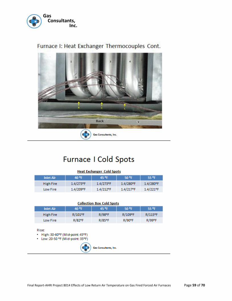
Preliminary work was conducted to ensure that heat exchanger temperatures tracked inlet air
temperatures, thus cold spot heat exchanger tests were conducted at 55⁰F, 50⁰F, 45⁰F and
40⁰F. It was found that for every drop of 1 degree in inlet air temperature there was a
corresponding drop of approx. 1 degree on the coldest spot on the heat exchanger.
One furnace (Furnace 5) being a “rooftop” product (non-condensing) and although designed
only to be installed outdoors, the spiking gas concentration was set as if it were using inside
combustion air in order to evaluate the heat exchanger design which is also used on
conventional indoor furnaces.
The remaining four furnaces (samples 1-4) were conventional, upflow, indoor household
products. Two were condensing products (samples 1 and 2) and two were non-condensing
(samples 3 and 4).
The AHRI committee selected various furnace designs which would give the broadest
evaluation with respect to manufacturing process (tubular heat exchangers vs.
formed/stamped heat exchangers), condensing and non-condensing products, and single and
two stage input / rate operation. All furnaces utilized inshot burners in conjunction with
induced combustion air blowers.

Gas Gas Consultants, Inc.
Final Report-AHRI Project 8014 Effects of Low Return Air Temperature on Gas Fired Forced Air Furnaces Page 7 of 70
FURNACE SPECIFICATIONS
Table 1
Upon completion of the corrosion cycling program, the heat exchangers of all furnaces were
examined for damage. No cracks, holes or perforations were found in any portions of any of
the condensing furnaces’ (Furnaces 1 and 2) flue collector boxes or either the primary or
secondary heat exchangers. All three non-condensing furnace’s (Furnaces 3, 4 and 5) flue
collector boxes had perforations due to corrosion. Additionally, Furnace 4 had a perforation in
the heat exchanger near where it joined the collector box.
Post cycling measurement of the flue gases showed that the air free CO levels were still passing
the ANSI Z21.47CSA 2.3 test criteria of 0.04% (400 ppm) as shown below.
BASELINE AND POST TEST CO AIR FREE DATA
Furnace Sample No. 1 2 3 4 5
Initial /Baseline
CO2 (%) 6.43 6.35 4.31 7.88 6.03 CO (ppm) air free 63 13 17 139 32
Post Corrosion Test
CO2 (%) 5.65 5.80 4.19 5.85 5.38 CO (ppm) air free 29 1 1 13 12
Table 2
Furnace Sample No.
Max. Input (BTU/Hr.)
Lo Fire Input (BTU/Hr.)
Type Furnace Type Heat Exchanger
Rise: Hi Fire / Lo Fire
& Test Rise
1 56,000 39,200 Condensing (96%) Tubular 30-60/20-50 45/35
2 60,000 39,000 Condensing (97%) “Clamshell” 35-65/35-65 50/50
3 60,000 39,000 Non-condensing (80%)
Squashed Tubular
30-60/20-50 45/35
4 66,000 43,500 Non-condensing (80%)
“Clamshell” 30-60/30-60 45/45
5 60,000 Nat Applicable Rooftop –Non-condensing (81%)
Tubular 30-60 45
Gas Gas Consultants, Inc.
Final Report-AHRI Project 8014 Effects of Low Return Air Temperature on Gas Fired Forced Air Furnaces Page 8 of 70
Note: Variations in values between pre and post cycling are normal variations due to the
difference in method of test setup. Pre-cycling is the standard ANSI Z21.47/CSA 2.3
combustion test protocol vent stack and post cycling was done in situ with all the vent
lengths and other apparatus used for the cycling test still in place. Of concerns is only
whether the air free CO values exceed 0.04% (400 ppm).
Gas Gas Consultants, Inc.
Final Report-AHRI Project 8014 Effects of Low Return Air Temperature on Gas Fired Forced Air Furnaces Page 9 of 70
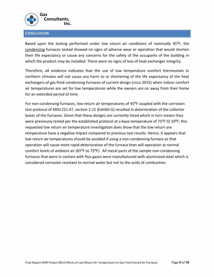
CONCLUSION
Based upon the testing performed under low return air conditions of nominally 45⁰F, the
condensing furnaces tested showed no signs of adverse wear or operation that would shorten
their life expectancy or cause any concerns for the safety of the occupants of the building in
which the product may be installed. There were no signs of loss of heat exchanger integrity.
Therefore, all evidence indicates that the use of low temperature comfort thermostats in
northern climates will not cause any harm to or shortening of the life expectancy of the heat
exchangers of gas fired condensing furnaces of current design (circa 2015) when indoor comfort
air temperatures are set for low temperatures while the owners are on away from their home
for an extended period of time.
For non-condensing furnaces, low return air temperatures of 45⁰F coupled with the corrosion
test protocol of ANSI Z21.47, section 2.15 (Exhibit G) resulted in deterioration of the collector
boxes of the furnaces. Given that these designs are currently listed which in turn means they
were previously tested per the established protocol at a base temperature of 75⁰F •} 10⁰F, this
requested low return air temperature investigation does show that the low return are
temperature have a negative impact compared to previous test results. Hence, it appears that
low return air temperatures should be avoided if using a non-condensing furnace as that
operation will cause more rapid deterioration of the furnace than will operation at normal
comfort levels of ambient air (65⁰F to 75⁰F). All metal parts of the sample non-condensing
furnaces that were in contact with flue gases were manufactured with aluminized steel which is
considered corrosion resistant to normal water but not to the acids of combustion.
Gas Gas Consultants, Inc.
Final Report-AHRI Project 8014 Effects of Low Return Air Temperature on Gas Fired Forced Air Furnaces Page 10 of 70
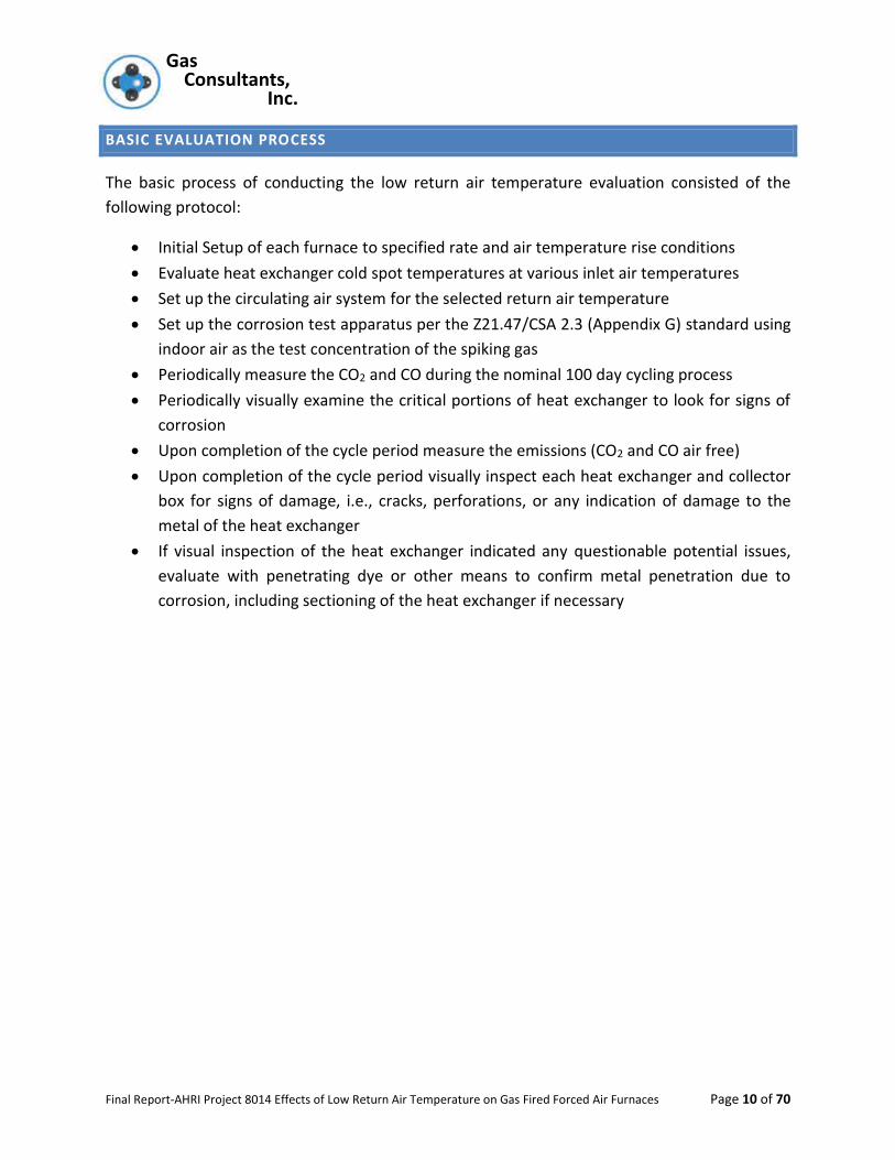
BASIC EVALUATION PROCESS
The basic process of conducting the low return air temperature evaluation consisted of the
following protocol:
Initial Setup of each furnace to specified rate and air temperature rise conditions
Evaluate heat exchanger cold spot temperatures at various inlet air temperatures
Set up the circulating air system for the selected return air temperature
Set up the corrosion test apparatus per the Z21.47/CSA 2.3 (Appendix G) standard using
indoor air as the test concentration of the spiking gas
Periodically measure the CO2 and CO during the nominal 100 day cycling process
Periodically visually examine the critical portions of heat exchanger to look for signs of
corrosion
Upon completion of the cycle period measure the emissions (CO2 and CO air free)
Upon completion of the cycle period visually inspect each heat exchanger and collector
box for signs of damage, i.e., cracks, perforations, or any indication of damage to the
metal of the heat exchanger
If visual inspection of the heat exchanger indicated any questionable potential issues,
evaluate with penetrating dye or other means to confirm metal penetration due to
corrosion, including sectioning of the heat exchanger if necessary
Gas Gas Consultants, Inc.
Final Report-AHRI Project 8014 Effects of Low Return Air Temperature on Gas Fired Forced Air Furnaces Page 11 of 70
INITIAL SETUP AND BASELINE DATA FOR FURNACE SAMPLES 1 THRU 5
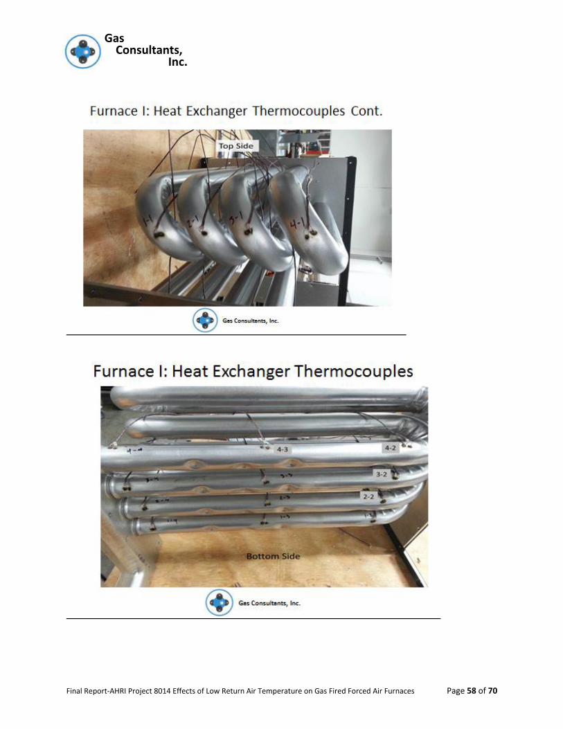
A quick check was made of the furnaces to see that they were performing satisfactorily and
then the heat exchangers were removed and thermocouples installed on the heat exchangers
at points that would most likely be the coldest spots and hottest spots. Since the furnaces were
already listed, the goal was not to identify the most critical temperatures but to find the
general trend of temperatures change as the inlet air temperatures were varied for later
portions of this program.
After attachment and documentation of the thermocouples the furnaces were reassembled
and the furnaces were setup for baseline testing.
All upflow furnaces (samples 1 thru 4) were attached to appropriate duct work as specified in
ANSI Z21.47/CSA 2.3. Since all furnaces vented vertically, the appropriate flue exhaust pipe as
specified in section 2.2.3 was attached to furnaces 3 and 4, consisting of an elbow, 2 feet of
horizontal pipe, another elbow and sufficient vertical pipe to terminate between 5 feet and 5
feet, six inches above the flue discharge of the furnace. Furnaces 1 and 2 used their maximum
specified length of PVC pipe.
The roof top packaged furnace had the appropriate duct work attached but the testing of
emissions was done directly at the discharge of the flue vent.
All furnaces were adjusted to their specified data plate input(±2%) per the procedures outlined
in Z21.47/CSA 2.3 and then adjusted to their rise conditions at both maximum and minimum
input (as appropriate). It was generally found that the low fire conditions were within
specification when received.
Baseline normal CO2 and air free CO was recorded after 15 minutes of operation from room
temperature. The flue gas temperatures were also recorded at steady state conditions.
Since the program ultimately would focus on the low fire operation of Furnace 1 through 4, the
“critical” setup condition was to obtain minimum input and minimum rate rise conditions. The
high fire condition would only be important for conduction of the post CO air free values at
normal input.
The results of the baseline setup is shown in the table below
BASELINE DATA PRIOR TO CORROSION CYCLING

Gas Gas Consultants, Inc.
Final Report-AHRI Project 8014 Effects of Low Return Air Temperature on Gas Fired Forced Air Furnaces Page 12 of 70
Table 3
Furnace Sample # #1 #2 #3 #4 #5
Max. Input Data
Data plate Input
(BTU/Hr.)
55,000 60,000 60,000 66,000 60,000
Rise Range (ºF)
30-60 35-65 36-60 30-60 30-60
Adjusted Rate (BTU/Hr.)
55,400 58,900 59,400 67,200 58,900
CO2 (%) 6.43 6.35 4.31 7.88 6.03
COAF (ppm) 63 13 17 139 32
Flue temp. @ Steady State
82.7 85.5 243.7 265.3 269.5
Blower Press. (“w.c.)
0.20 0.20 0.20 0.20 0.20
Rise 45.1 48.2 44.1 45 43.9
Required Spiking gas
flow (mL/Min
Date 12/4/14 1/6/15 1/15/15 12/3/14 1/22/15
Min. Input Data
Data plate Input
(BTU/Hr.)
39,200 39,000 39,000 43,500 Not Applicable
Rise Range (ºF)
20-50 35-65 20-50 30-60
Adjusted Rate (BTU/Hr.)
38,900 39,000 38,400 42,600
CO2 (%) 5.49 5.41 3.27 5.64
COAF (ppm) 71 5 15 43
Flue temp. @ Steady State
78.3 91.1 201.8 221.4
Blower Press. (“ w.c.)
0.15 0.10 0.11 44.4
Date 12/4/14 1/7/15 1/16/15 12/3/14
Gas Gas Consultants, Inc.
Final Report-AHRI Project 8014 Effects of Low Return Air Temperature on Gas Fired Forced Air Furnaces Page 13 of 70
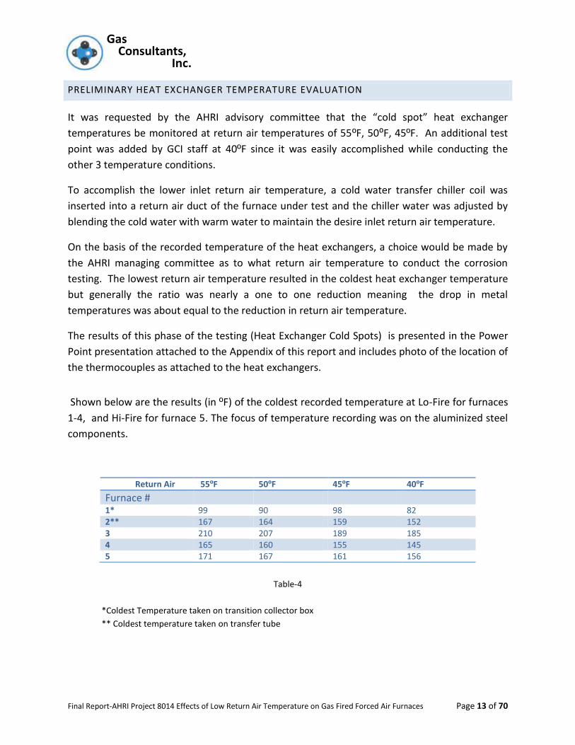
PRELIMINARY HEAT EXCHANGER TEMPERATURE EVALUATION
It was requested by the AHRI advisory committee that the “cold spot” heat exchanger
temperatures be monitored at return air temperatures of 55ºF, 50⁰F, 45ºF. An additional test
point was added by GCI staff at 40ºF since it was easily accomplished while conducting the
other 3 temperature conditions.
To accomplish the lower inlet return air temperature, a cold water transfer chiller coil was
inserted into a return air duct of the furnace under test and the chiller water was adjusted by
blending the cold water with warm water to maintain the desire inlet return air temperature.
On the basis of the recorded temperature of the heat exchangers, a choice would be made by
the AHRI managing committee as to what return air temperature to conduct the corrosion
testing. The lowest return air temperature resulted in the coldest heat exchanger temperature
but generally the ratio was nearly a one to one reduction meaning the drop in metal
temperatures was about equal to the reduction in return air temperature.
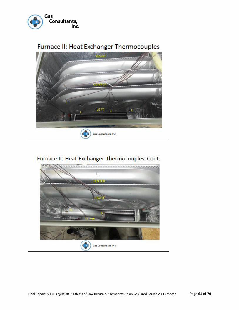
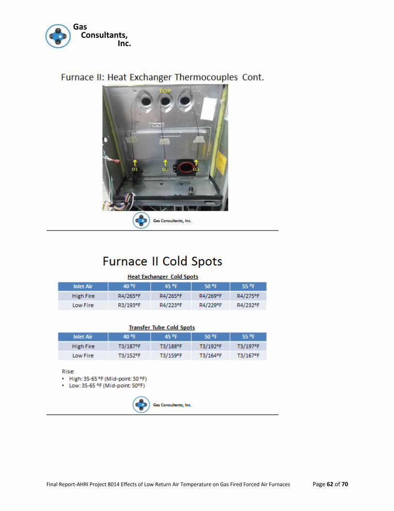
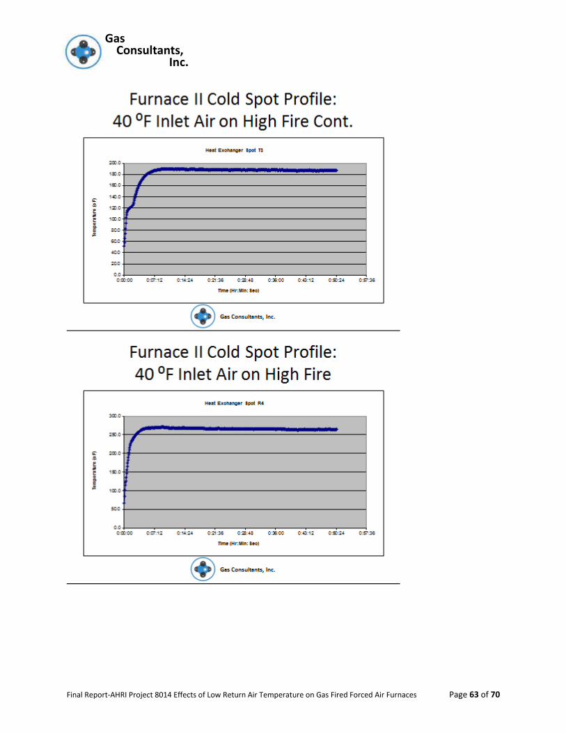
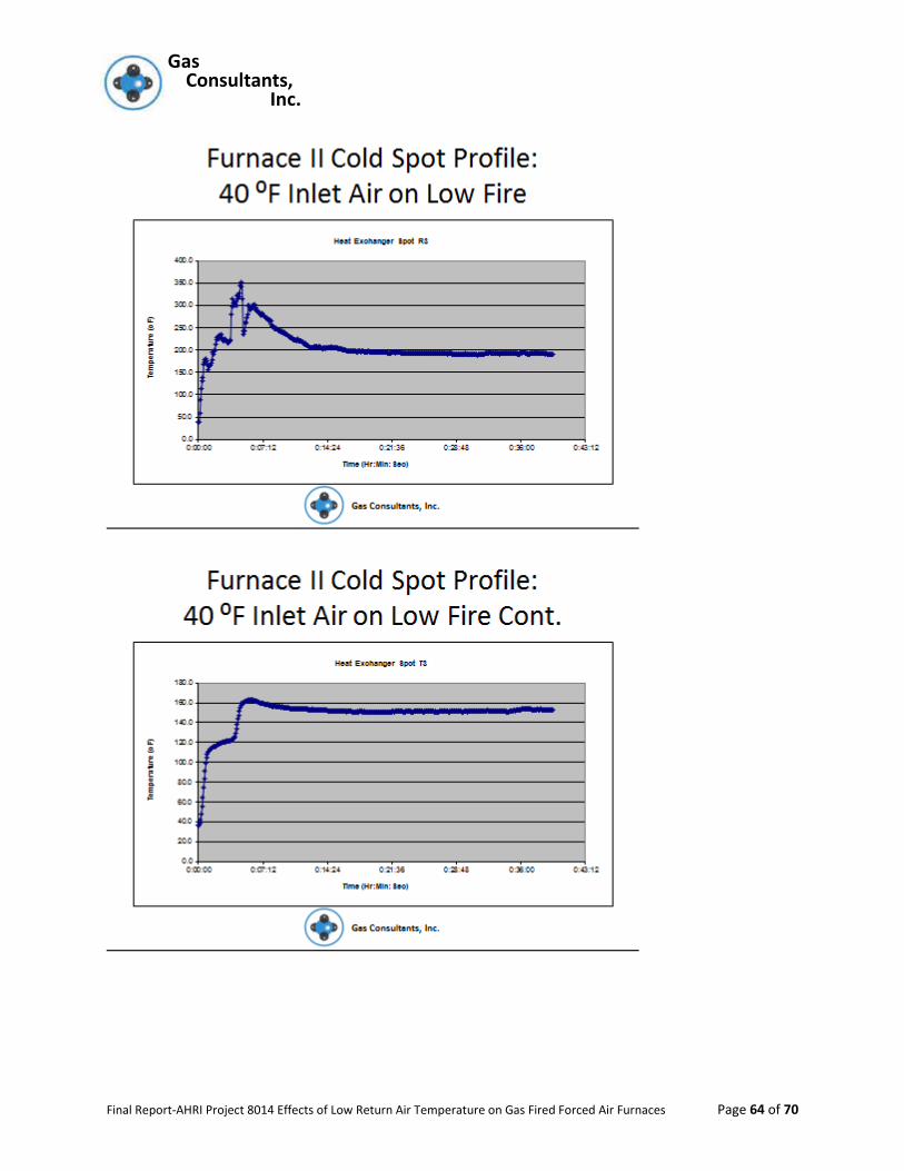
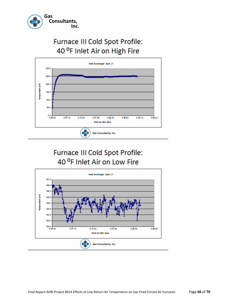
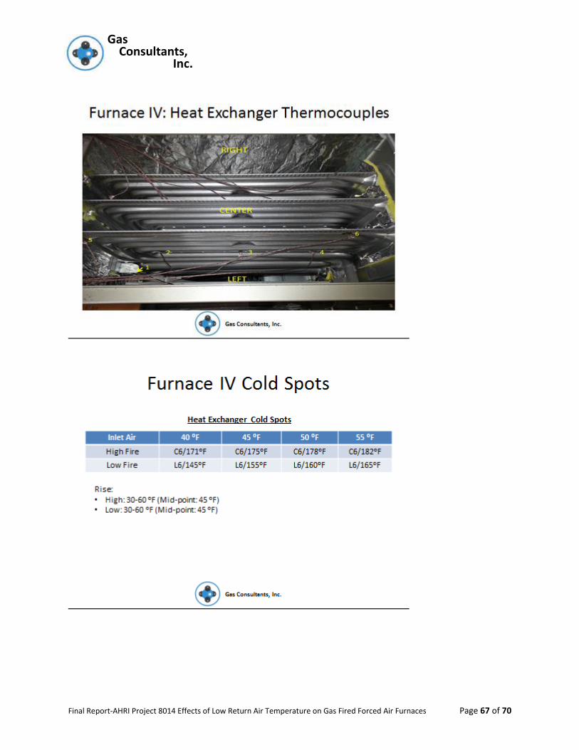
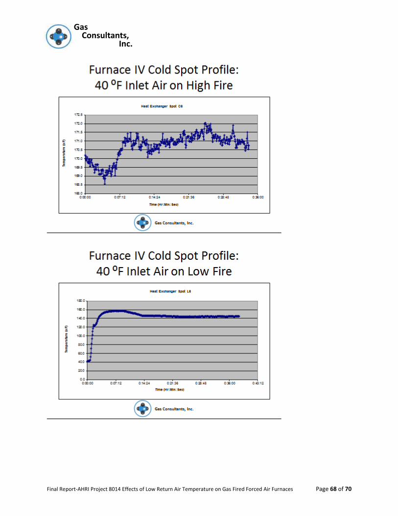
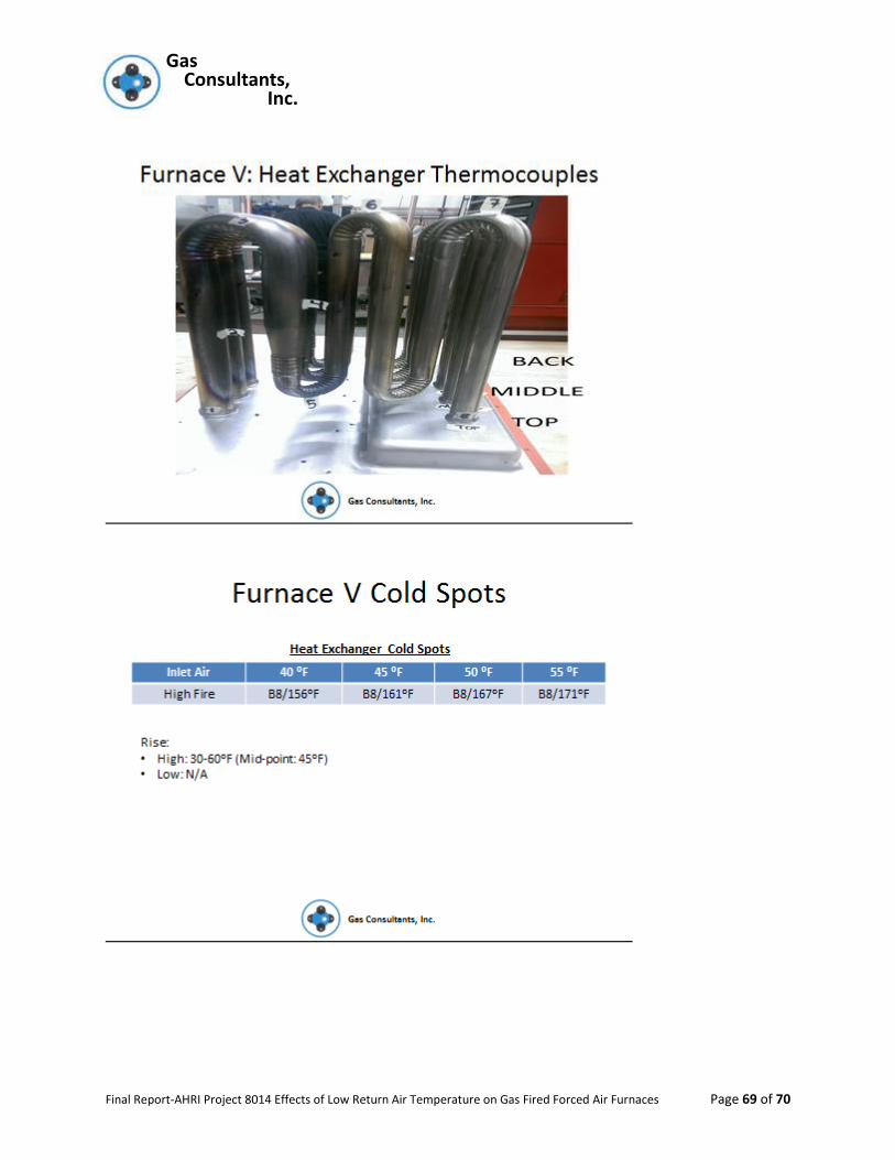
The results of this phase of the testing (Heat Exchanger Cold Spots) is presented in the Power
Point presentation attached to the Appendix of this report and includes photo of the location of
the thermocouples as attached to the heat exchangers.
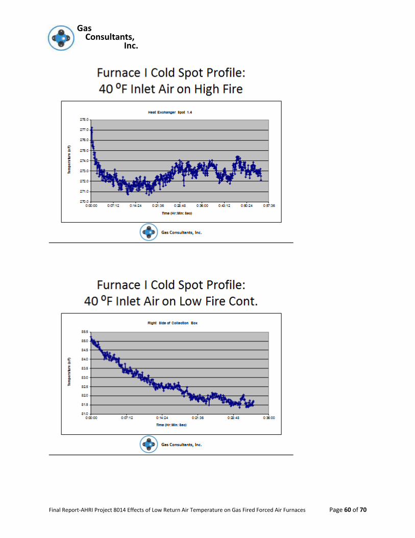
Shown below are the results (in ºF) of the coldest recorded temperature at Lo-Fire for furnaces
1-4, and Hi-Fire for furnace 5. The focus of temperature recording was on the aluminized steel
components.
Table-4
*Coldest Temperature taken on transition collector box
** Coldest temperature taken on transfer tube
Return Air 55ºF 50ºF 45ºF 40ºF
Furnace #
1* 99 90 98 82 2** 167 164 159 152 3 210 207 189 185 4 165 160 155 145 5 171 167 161 156
Gas Gas Consultants, Inc.
Final Report-AHRI Project 8014 Effects of Low Return Air Temperature on Gas Fired Forced Air Furnaces Page 14 of 70
As can be seen, and as one would expect, the heat exchanger temperatures tracked the inlet air
temperature on an almost 1:1 ratio.
Based upon the results of the above recorded temperatures, the AHRI advisory committee
agreed that the 45ºF inlet air temperature should be the return air temperature and
combustion air temperature used for this investigation.
Gas Gas Consultants, Inc.
Final Report-AHRI Project 8014 Effects of Low Return Air Temperature on Gas Fired Forced Air Furnaces Page 15 of 70
PRELIMINARY EVALUATION
Section G.1.9 of the Corrosion Test in Z21.47/CSA 2.3 requires that the furnace be operated at
the lowest rate that the burner can be operated at on a full time basis. Four of the five
furnaces (samples 1, 2, 3, and 4) were two stage combustion systems that can remain in the
low fire mode indefinitely, hence the corrosion testing would be conducted at the minimum
input as detailed on their data plates.
All four units change their combustion blower speed when they operate at the minimum input,
hence, the low fire input and flue gas CO2 was used as the basis of the calculation for
establishing the nominal Spiking Gas Flow as determined by using Figure G5 of Z21.47/CSA 2.3
and the following formula given below fig. G5
𝐴𝑐𝑡𝑢𝑎𝑙 𝐹𝑙𝑜𝑤 (𝑚𝐿
min) =
𝑁𝑜𝑚𝑖𝑛𝑎𝑙(𝑚𝐿
min)×
𝑅𝑎𝑡𝑒𝑑 𝐼𝑛𝑝𝑢𝑡 (𝐵𝑡𝑢𝐻𝑟 )
100,000 𝐵𝑡𝑢/𝐻𝑟×
𝑁𝑜𝑚𝑖𝑛𝑎𝑙 𝑆𝑝𝑖𝑘𝑖𝑛𝑔 𝐺𝑎𝑠 𝑀𝑖𝑥𝑡𝑢𝑟𝑒 𝑝𝑝𝑚 𝑜𝑟 %
𝐴𝑐𝑡𝑢𝑎𝑙 𝑆𝑝𝑖𝑘𝑖𝑛𝑔 𝐺𝑎𝑠 𝑀𝑖𝑥𝑡𝑢𝑟𝑒 𝑝𝑝𝑚 𝑜𝑟 %)
The cylinders of spiking gas delivered were within the ±2% tolerance required, hence, the
formula is reduced to:
𝐴𝑐𝑡𝑢𝑎𝑙 𝐹𝑙𝑜𝑤 (𝑚𝐿
min) = 𝑁𝑜𝑚𝑖𝑛𝑎𝑙(
𝑚𝐿
min)×
𝑅𝑎𝑡𝑒𝑑 𝐼𝑛𝑝𝑢𝑡 (𝐵𝑡𝑢𝐻𝑟 )
100,000 𝐵𝑡𝑢/𝐻𝑟
Before starting the corrosion testing each furnace had its input and baseline CO2 and CO air free
values determined (see above). Of primary importance for sample 1 through 4 was the low fire
input values. If a furnace was found to be outside the ±2% limit detailed in clause 2.5.4 of the
ANSI Z21.47/CSA 2.3, the manifold pressure was adjusted to obtain the required BTU/Hr. input
on the data plate. The low fire CO2 values of samples 1, 2, 3, and 4 were needed in order to
arrive at the proper spiking gas flow as detailed in Z21.47/CSA 2.3, section 2.15. Since sample 5
was not a two stage combustion system, only the full input data needed to be addressed.
Based upon the above data for minimum input for samples 1 through 4 and maximum input for
sample 5 the following flow rates of spiking gas were determined for this evaluation.
Gas Gas Consultants, Inc.
Final Report-AHRI Project 8014 Effects of Low Return Air Temperature on Gas Fired Forced Air Furnaces Page 16 of 70
Table 5
150 mm glass flowmeters were used to determine the flow to each furnace and throughout the
cycling the flow rates were monitored to confirm there was no drift in the control mechanism.
Furnace 1 was listed for and set up with 65’ of PVC exhaust pipe and furnace 2 was listed for
and setup with 200’ of PVC exhaust pipe. Samples 3 – 5 were set up with vertical metallic pipe
that then traversed vertically and horizontally to the central collector exhaust hood.
The rise and static pressure conditions were established with the appropriate duct work at a
return air temperature of 70ºF at full input. Again samples 1 through 4 needed the rise
established while operating at low fire conditions and sample 5 only needed the high fire rise
condition. The static pressure for samples 1-4 varied from that used at normal input.
Based upon the above heat exchanger temperatures, each furnace was also equipped with a
removable panel that would allow visual inspection of the heat exchangers where it was
expected that corrosion might occur. This would permit constant surveillance of the possible
issues before the end on the cycling period.
FLOW RATES FOR SPIKING GAS
Furnace Sample # #1 #2 #3 #4 #5
Flow Rate (mL/min) 85 86 135 91 118
Gas Gas Consultants, Inc.
Final Report-AHRI Project 8014 Effects of Low Return Air Temperature on Gas Fired Forced Air Furnaces Page 17 of 70
TEST STRUCTURE FOR MAINTAING RETURN AIR TEMPERATURE
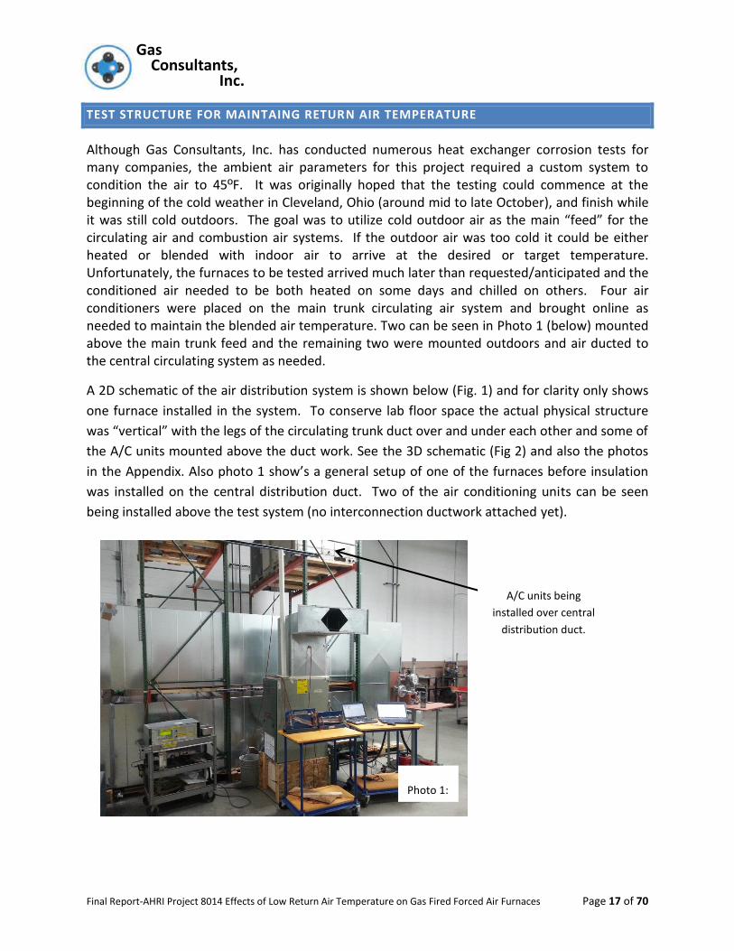
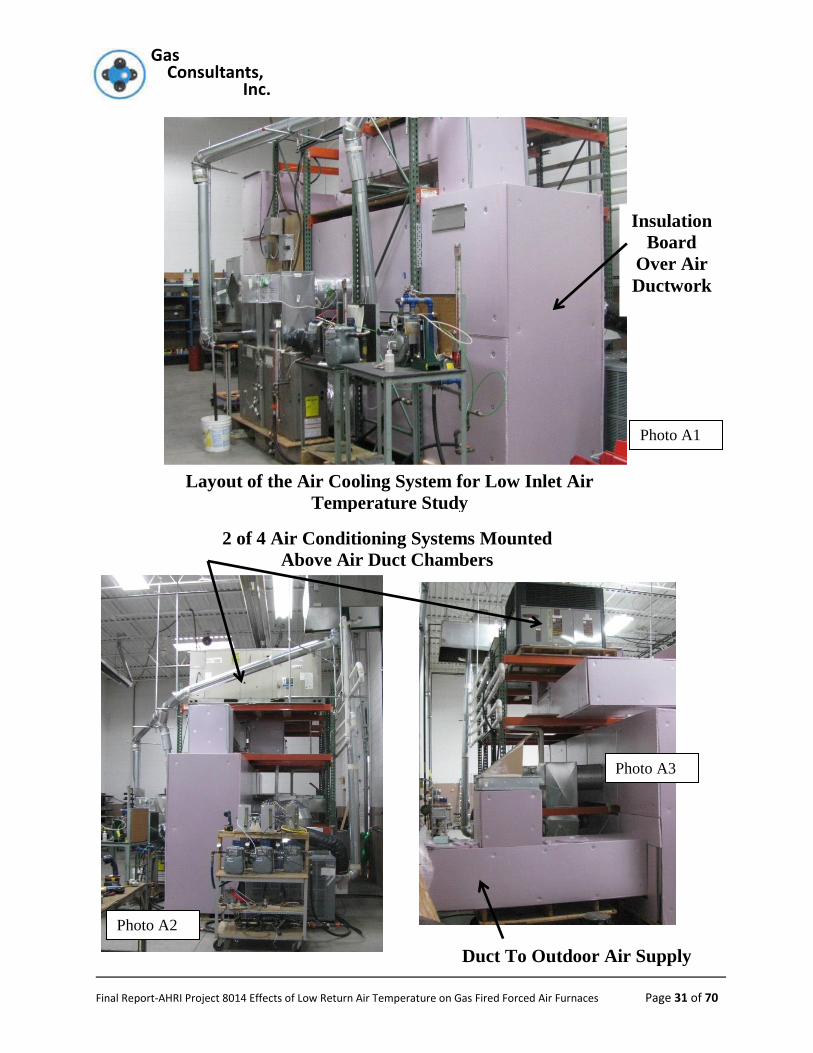
Although Gas Consultants, Inc. has conducted numerous heat exchanger corrosion tests for many companies, the ambient air parameters for this project required a custom system to condition the air to 45ºF. It was originally hoped that the testing could commence at the beginning of the cold weather in Cleveland, Ohio (around mid to late October), and finish while it was still cold outdoors. The goal was to utilize cold outdoor air as the main “feed” for the circulating air and combustion air systems. If the outdoor air was too cold it could be either heated or blended with indoor air to arrive at the desired or target temperature. Unfortunately, the furnaces to be tested arrived much later than requested/anticipated and the conditioned air needed to be both heated on some days and chilled on others. Four air conditioners were placed on the main trunk circulating air system and brought online as needed to maintain the blended air temperature. Two can be seen in Photo 1 (below) mounted above the main trunk feed and the remaining two were mounted outdoors and air ducted to the central circulating system as needed.
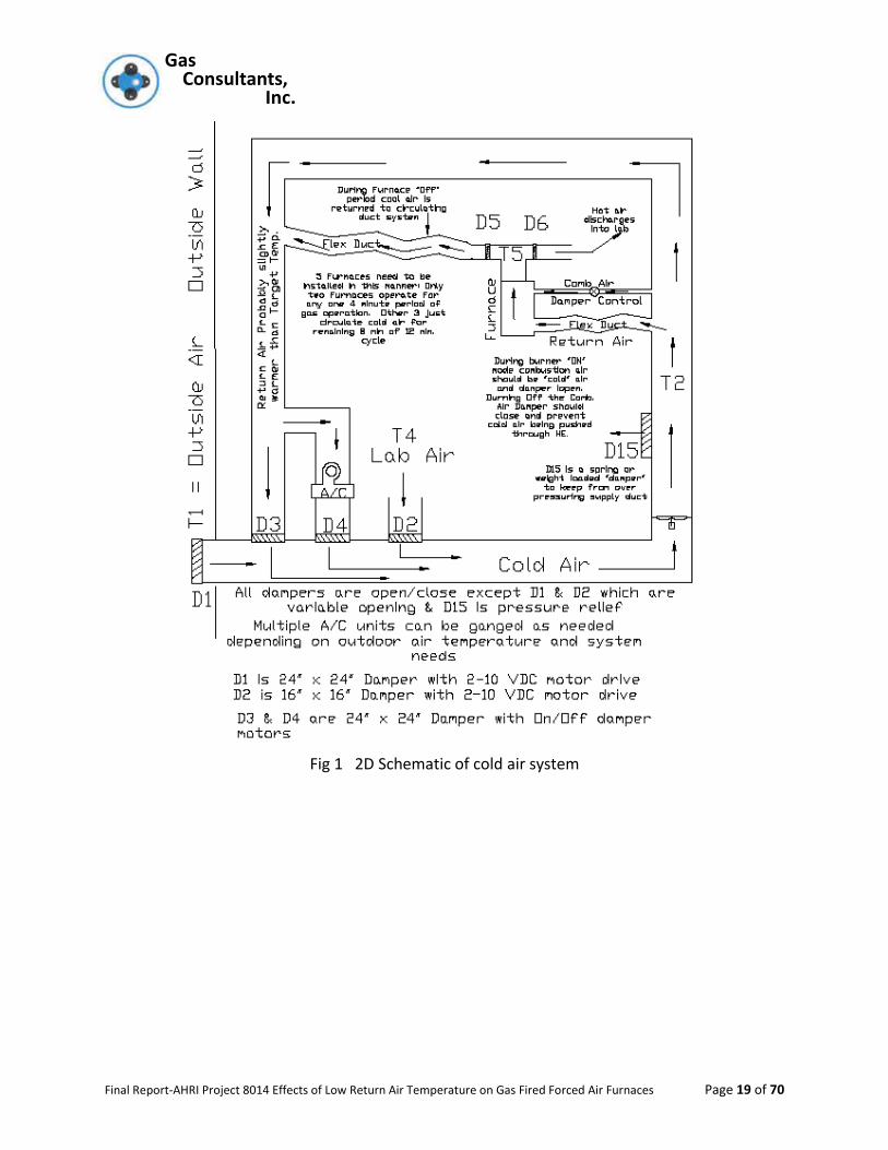
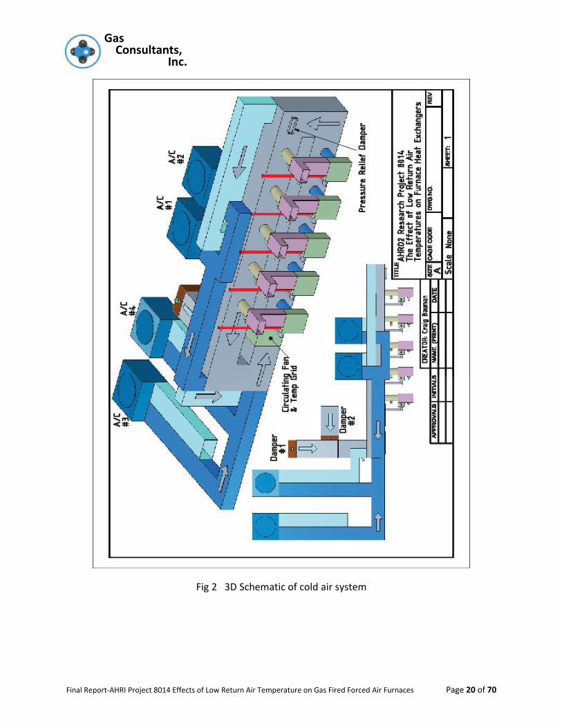
A 2D schematic of the air distribution system is shown below (Fig. 1) and for clarity only shows
one furnace installed in the system. To conserve lab floor space the actual physical structure
was “vertical” with the legs of the circulating trunk duct over and under each other and some of
the A/C units mounted above the duct work. See the 3D schematic (Fig 2) and also the photos
in the Appendix. Also photo 1 show’s a general setup of one of the furnaces before insulation
was installed on the central distribution duct. Two of the air conditioning units can be seen
being installed above the test system (no interconnection ductwork attached yet).
Photo 1:
A/C units being
installed over central
distribution duct.
Gas Gas Consultants, Inc.
Final Report-AHRI Project 8014 Effects of Low Return Air Temperature on Gas Fired Forced Air Furnaces Page 18 of 70
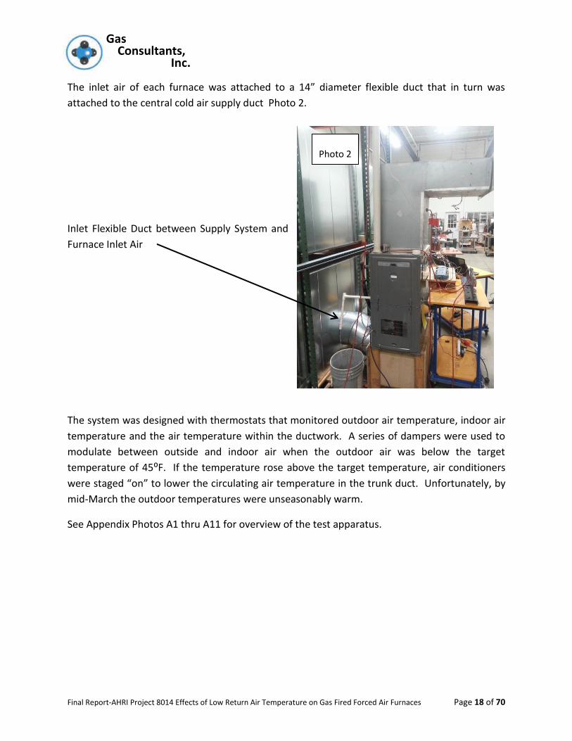
The inlet air of each furnace was attached to a 14” diameter flexible duct that in turn was
attached to the central cold air supply duct Photo 2.
Inlet Flexible Duct between Supply System and
Furnace Inlet Air
The system was designed with thermostats that monitored outdoor air temperature, indoor air
temperature and the air temperature within the ductwork. A series of dampers were used to
modulate between outside and indoor air when the outdoor air was below the target
temperature of 45⁰F. If the temperature rose above the target temperature, air conditioners
were staged “on” to lower the circulating air temperature in the trunk duct. Unfortunately, by
mid-March the outdoor temperatures were unseasonably warm.
See Appendix Photos A1 thru A11 for overview of the test apparatus.
Photo 2
Gas Gas Consultants, Inc.
Final Report-AHRI Project 8014 Effects of Low Return Air Temperature on Gas Fired Forced Air Furnaces Page 19 of 70
Fig 1 2D Schematic of cold air system
Gas Gas Consultants, Inc.
Final Report-AHRI Project 8014 Effects of Low Return Air Temperature on Gas Fired Forced Air Furnaces Page 20 of 70
Fig 2 3D Schematic of cold air system
Gas Gas Consultants, Inc.
Final Report-AHRI Project 8014 Effects of Low Return Air Temperature on Gas Fired Forced Air Furnaces Page 21 of 70
Referring to the schematic above, each furnace was equipped with two dampers in the warm
air discharge plenum. While in the heating mode the “hot” air was diverted into the lab space
with damper D6 open and damper D5 closed. During the furnace off cycle and once the furnace
discharge air temperature dropped to the temperature of the main cold feed system (nominally
45ºF), damper D6 closed and damper D5 opened such that the “cold” air would be returned to
the cold air delivery system and not wasted or dumped into the lab space.
The design of the system was such that two furnaces were on for 4 minutes while three
furnaces were in the cool down mode. Then when the first two started their cool down period,
two more furnaces started their 4 minute operational cycle. When those two furnaces
completed 4 minutes of burn time, the burners turned off and they started into their cool down
period. At that point the fifth furnace came on for its four minute cycle. When the fifth furnace
completed its four minute “on” cycle, the process started over, i.e., furnaces 1 and 2 started
back up. The total corrosion test cycle is to be 4 minutes “on” and 8 minutes “off” for a total of
12,000 cycles or 800 hours of burner on time.
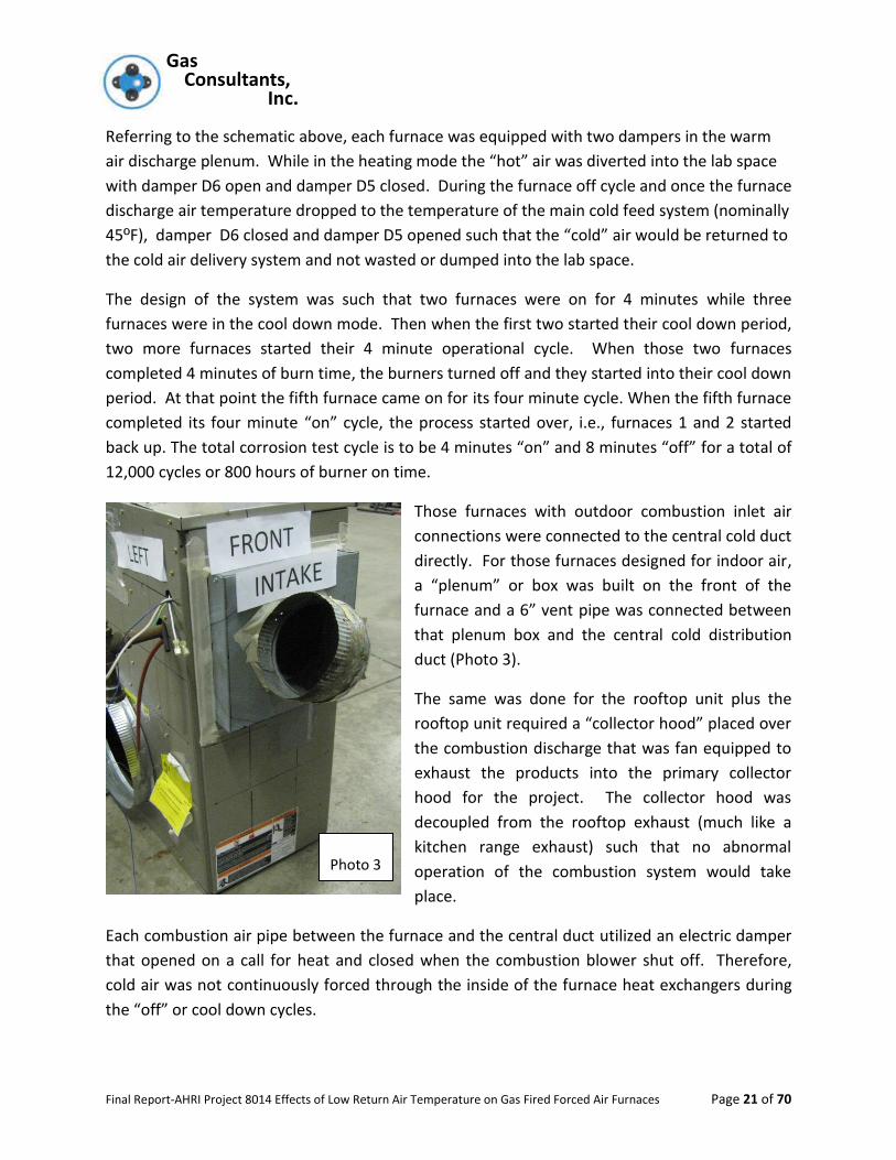
Those furnaces with outdoor combustion inlet air
connections were connected to the central cold duct
directly. For those furnaces designed for indoor air,
a “plenum” or box was built on the front of the
furnace and a 6” vent pipe was connected between
that plenum box and the central cold distribution
duct (Photo 3).
The same was done for the rooftop unit plus the
rooftop unit required a “collector hood” placed over
the combustion discharge that was fan equipped to
exhaust the products into the primary collector
hood for the project. The collector hood was
decoupled from the rooftop exhaust (much like a
kitchen range exhaust) such that no abnormal
operation of the combustion system would take
place.
Each combustion air pipe between the furnace and the central duct utilized an electric damper
that opened on a call for heat and closed when the combustion blower shut off. Therefore,
cold air was not continuously forced through the inside of the furnace heat exchangers during
the “off” or cool down cycles.
Photo 3
Gas Gas Consultants, Inc.
Final Report-AHRI Project 8014 Effects of Low Return Air Temperature on Gas Fired Forced Air Furnaces Page 22 of 70
The maximum vent length exhaust pipes of units 1 through 4 were plumbed into a collection
hood at the ceiling and the exhaust products were drafted to the outdoors. See Appendix Photo
A2.
The test gas used for spiking was 30,000 ppm (3%) of methyl chloride, 10,000 ppm (1%) methyl
fluoride in nitrogen. The gases used were all analyzed by an ISO 17025 lab and were within ±2%
(actual- 1.7%) of the required constituent’s concentration. See Appendix Photos A7 thru A9.
The cycling apparatus for the actual corrosion testing was the same as that detailed in clause 2.15 of Z21.47/CSA 2.3 appendix G. Thus each furnace had a dedicated corrosion cycling system consisting of valves, flow meter, gas meter, leak checker bottle, etc. A common timing system was used due to the required sequencing of the five furnaces. Also a central spiking gas supply system was used to feed the spiking gas to the individual furnace spiking gas systems.
If the central cold air supply temperature went outside of the temperature limitation of 45ºF ± 5ºF, the system allow the current (in process) cycle to be completed but then stopped the cycling apparatus and held the system in a “hold” mode until the inlet air temperature was back within specifications. To prevent possible rapid on and off operation due to return air temperature fluctuations, a minimum down time was specified of 30 minutes before cycling could be reinstated.
The total down time due to temperature excursions outside of the limits was 24 days for Furnace 1, 2, 3 and 5 with a total down time for any one event was no more than 2 days. Because Furnace 4 experienced issues with CO levels, its total down time was 30 days with an single off period of 6 days. Although clause 2.15 calls for no more than 20 days of “down” time it was not possible to stay within these confined conditions due to some abnormally warm temperatures that occurred. It was felt that more incidents of down time would be a more adverse situation and visual and intermediate tests indicated that no issues were being experienced by the higher than permitted “down” days.
Through the use of dataloggers, the temperature of the plenum air temperature was tracked once per minute over the course of the whole testing and the average air temperature during run cycles was 46.1ºF.
Gas Gas Consultants, Inc.
Final Report-AHRI Project 8014 Effects of Low Return Air Temperature on Gas Fired Forced Air Furnaces Page 23 of 70
POST CORROSION CYCLING RESULTS
The cycling program was begun on Feb. 25, 2015. Although there were two air conditioning
units installed in the system with approx. 7 tons of air conditioning, later in the program, as the
weather became substantially warmer, the system was shut down while two more air
conditioning systems (approx. 7 additional tons) were installed in the air duct system.
The data, photographs, examination for failure points and dismantling all took place within 10
days after cycling was completed.
The data recorded during the cycling testing is shown below for each furnace.
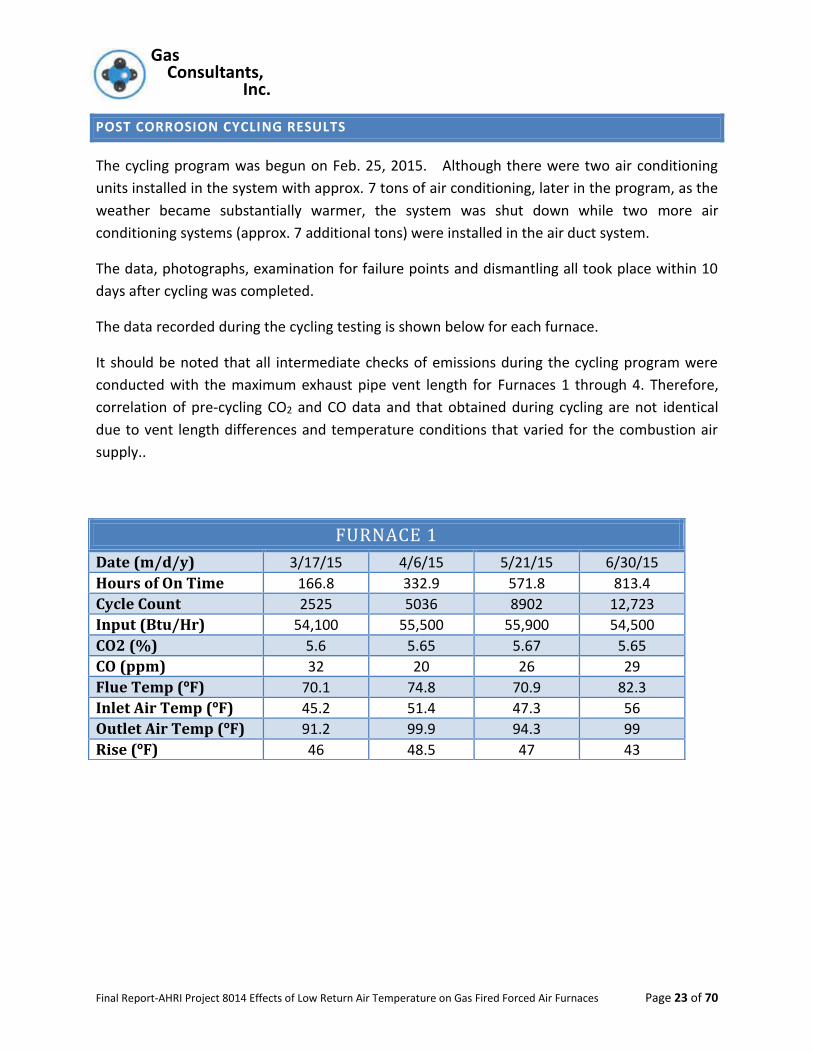
It should be noted that all intermediate checks of emissions during the cycling program were
conducted with the maximum exhaust pipe vent length for Furnaces 1 through 4. Therefore,
correlation of pre-cycling CO2 and CO data and that obtained during cycling are not identical
due to vent length differences and temperature conditions that varied for the combustion air
supply..
FURNACE 1
Date (m/d/y) 3/17/15 4/6/15 5/21/15 6/30/15
Hours of On Time 166.8 332.9 571.8 813.4
Cycle Count 2525 5036 8902 12,723
Input (Btu/Hr) 54,100 55,500 55,900 54,500
CO2 (%) 5.6 5.65 5.67 5.65
CO (ppm) 32 20 26 29
Flue Temp (ºF) 70.1 74.8 70.9 82.3
Inlet Air Temp (ºF) 45.2 51.4 47.3 56
Outlet Air Temp (ºF) 91.2 99.9 94.3 99
Rise (ºF) 46 48.5 47 43
Gas Gas Consultants, Inc.
Final Report-AHRI Project 8014 Effects of Low Return Air Temperature on Gas Fired Forced Air Furnaces Page 24 of 70
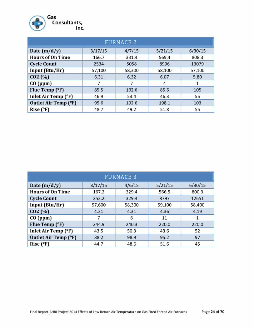
FURNACE 2
Date (m/d/y) 3/17/15 4/7/15 5/21/15 6/30/15
Hours of On Time 166.7 331.4 569.4 808.3
Cycle Count 2534 5058 8996 13079
Input (Btu/Hr) 57,100 58,300 58,100 57,100
CO2 (%) 6.31 6.32 6.07 5.80
CO (ppm) 7 7 4 1
Flue Temp (ºF) 85.5 102.6 85.6 105
Inlet Air Temp (ºF) 46.9 53.4 46.3 55
Outlet Air Temp (ºF) 95.6 102.6 198.1 103
Rise (ºF) 48.7 49.2 51.8 55
FURNACE 3
Date (m/d/y) 3/17/15 4/6/15 5/21/15 6/30/15
Hours of On Time 167.2 329.4 566.5 800.3
Cycle Count 252.2 329.4 8797 12651
Input (Btu/Hr) 57,600 58,300 59,100 58,400
CO2 (%) 4.21 4.31 4.36 4.19
CO (ppm) 7 6 11 1
Flue Temp (ºF) 244.9 240.3 220.0 220.0
Inlet Air Temp (ºF) 43.5 50.3 43.6 52
Outlet Air Temp (ºF) 88.2 98.9 95.2 97
Rise (ºF) 44.7 48.6 51.6 45
Gas Gas Consultants, Inc.
Final Report-AHRI Project 8014 Effects of Low Return Air Temperature on Gas Fired Forced Air Furnaces Page 25 of 70
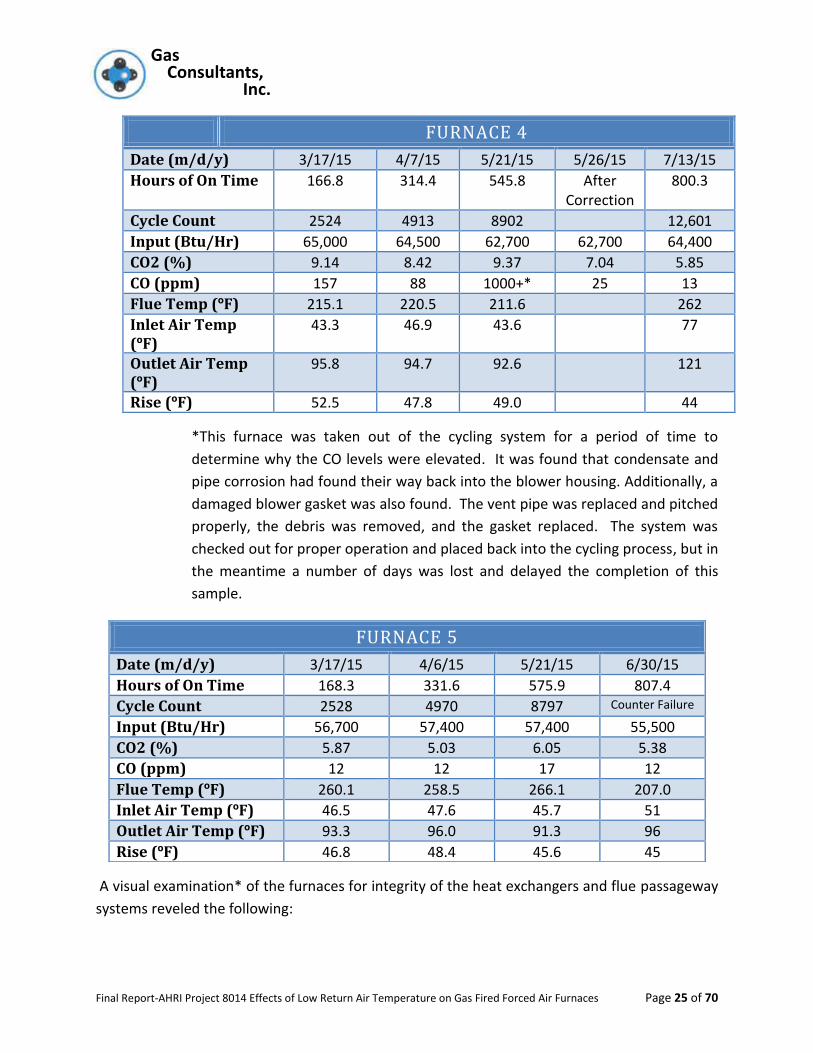
*This furnace was taken out of the cycling system for a period of time to
determine why the CO levels were elevated. It was found that condensate and
pipe corrosion had found their way back into the blower housing. Additionally, a
damaged blower gasket was also found. The vent pipe was replaced and pitched
properly, the debris was removed, and the gasket replaced. The system was
checked out for proper operation and placed back into the cycling process, but in
the meantime a number of days was lost and delayed the completion of this
sample.
A visual examination* of the furnaces for integrity of the heat exchangers and flue passageway
systems reveled the following:
FURNACE 4
Date (m/d/y) 3/17/15 4/7/15 5/21/15 5/26/15 7/13/15
Hours of On Time 166.8 314.4 545.8 After Correction
800.3
Cycle Count 2524 4913 8902 12,601
Input (Btu/Hr) 65,000 64,500 62,700 62,700 64,400
CO2 (%) 9.14 8.42 9.37 7.04 5.85
CO (ppm) 157 88 1000+* 25 13
Flue Temp (ºF) 215.1 220.5 211.6 262
Inlet Air Temp (ºF)
43.3 46.9 43.6 77
Outlet Air Temp (ºF)
95.8 94.7 92.6 121
Rise (ºF) 52.5 47.8 49.0 44
FURNACE 5
Date (m/d/y) 3/17/15 4/6/15 5/21/15 6/30/15
Hours of On Time 168.3 331.6 575.9 807.4
Cycle Count 2528 4970 8797 Counter Failure
Input (Btu/Hr) 56,700 57,400 57,400 55,500
CO2 (%) 5.87 5.03 6.05 5.38
CO (ppm) 12 12 17 12
Flue Temp (ºF) 260.1 258.5 266.1 207.0
Inlet Air Temp (ºF) 46.5 47.6 45.7 51
Outlet Air Temp (ºF) 93.3 96.0 91.3 96
Rise (ºF) 46.8 48.4 45.6 45

Gas Gas Consultants, Inc.
Final Report-AHRI Project 8014 Effects of Low Return Air Temperature on Gas Fired Forced Air Furnaces Page 26 of 70
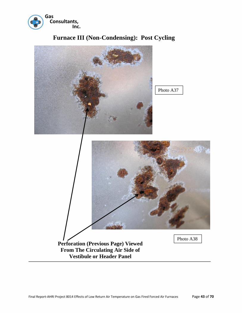
*If one finds any signs of corrosion on the circulating air side of the metal parts it is an
almost positive indicator that corrosion from the interior has eaten a hole through to
the exterior surface. That surface will become an eventual pathway if penetrating dyes
or other leak checkers are used.
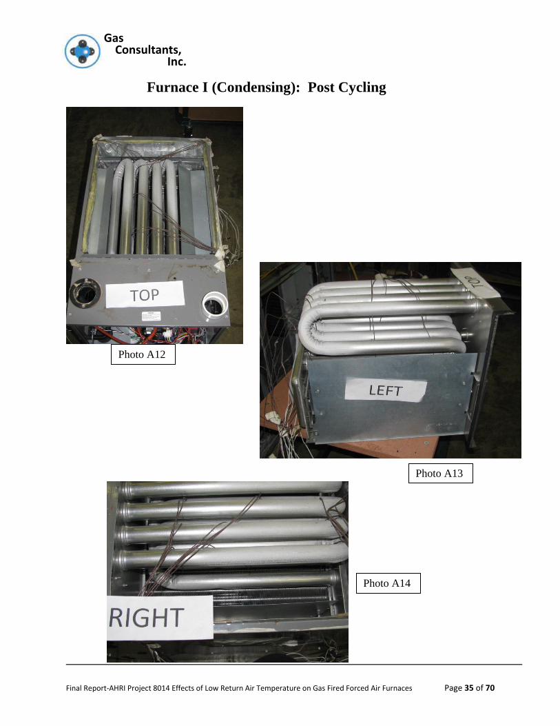
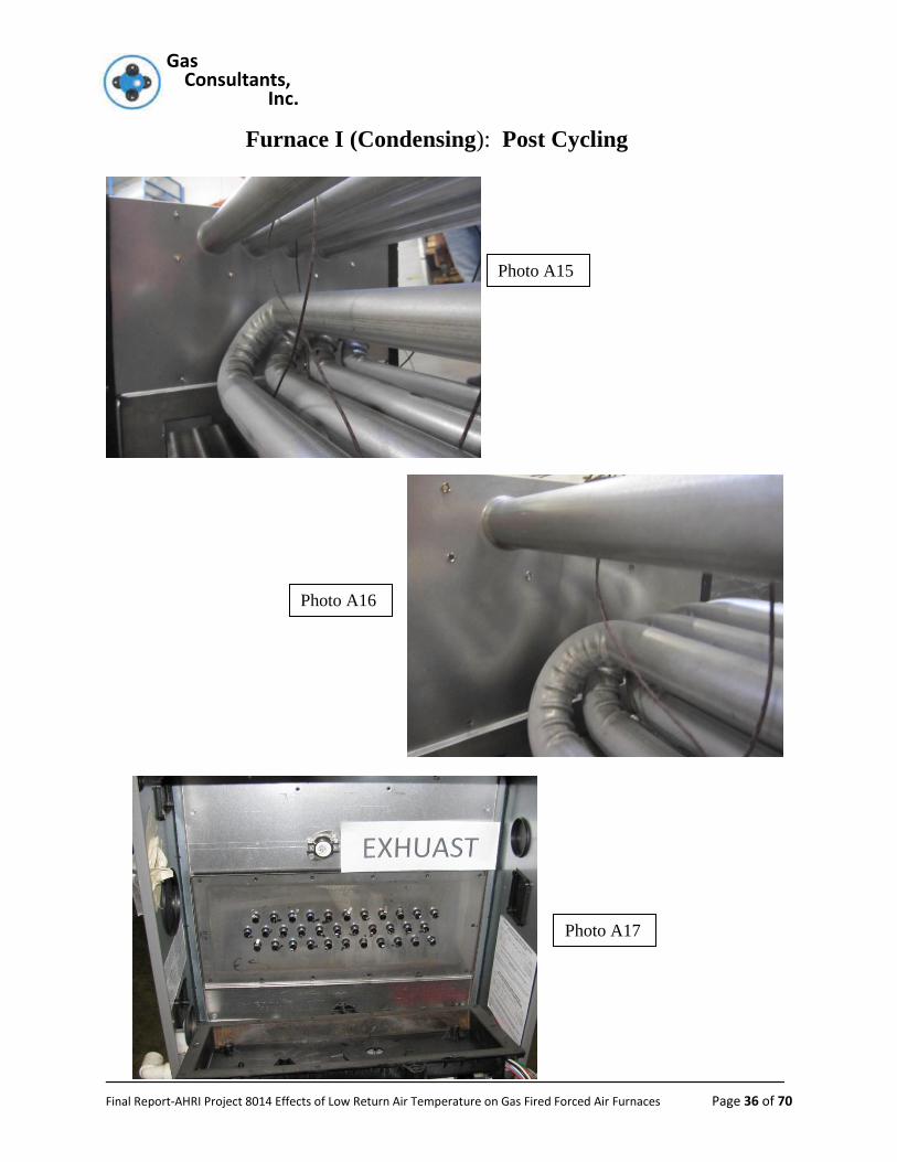
Furnace 1 (Condensing): Appendix Photos A12 – A21
There was no sign of corrosion on any metallic surfaces in the circulating air side of
the furnace.
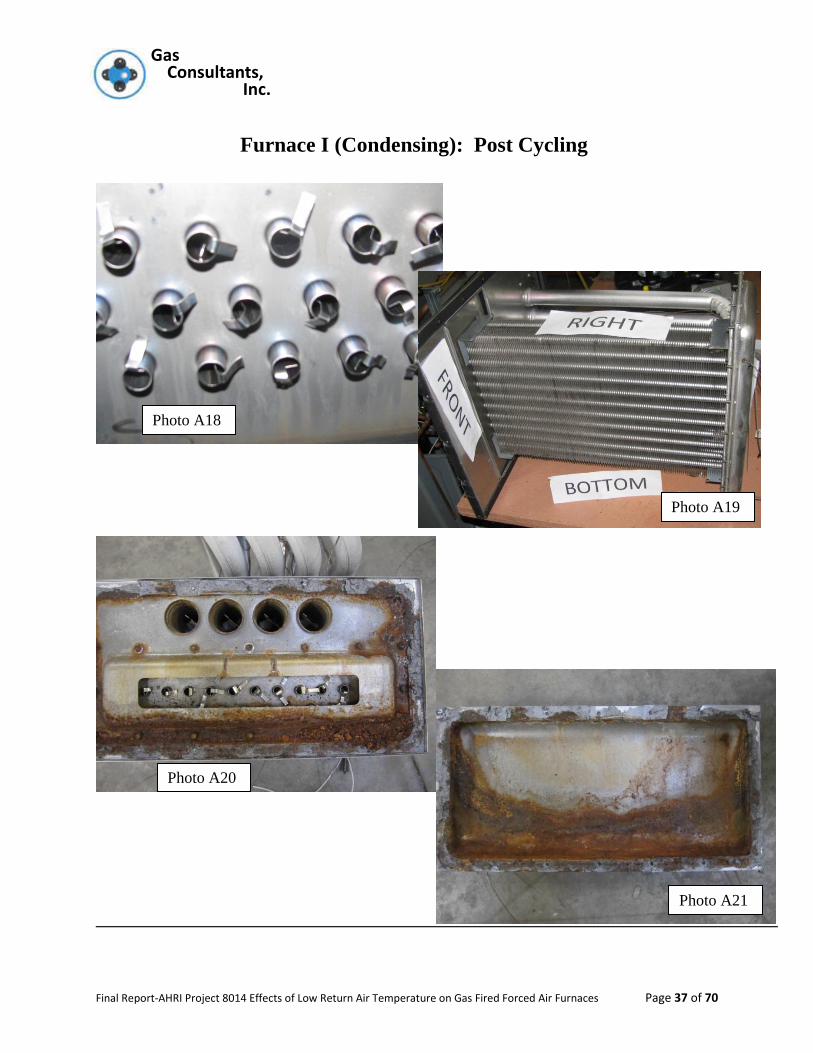
The primary heat exchanger was in excellent shape both on the exterior and interior
portions with no signs of pinholes or rust penetration.
The secondary heat exchanger baffles were examined and found to be in good
condition.
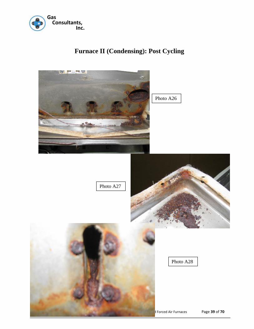
Furnace 2 (Condensing): Appendix Photos A22 – A31
There were no signs of corrosion any metallic surfaces in the circulating air side of
the furnace.
The primary heat exchanger was in excellent shape both on the exterior and interior
portions with no signs of pinholes or rust penetration.
The distribution box between the primary and secondary heat exchanger was
examined and although it contained some corrosion there was no severe attack of
the metal.
The secondary heat exchanger baffles were examined and found to be in good
condition.
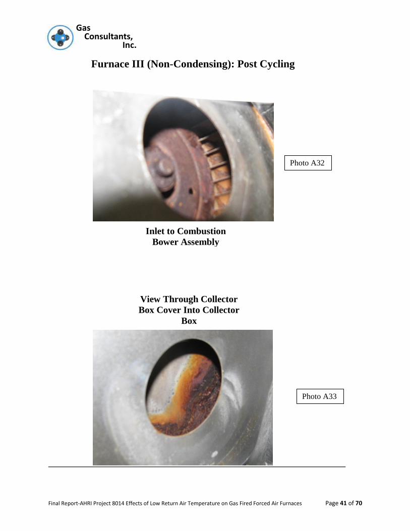
Furnace 3 (Non-Condensing): Appendix Photos A32 – A42
There were no signs of corrosion any metallic surfaces on of the heat exchanger
tubes on the circulating air side of the furnace.
The interior surfaces of the heat exchanger tubes showed some signs of corrosion
on the discharge (exit) portion of the heat exchanger tubes but no penetrations had
occurred
The collector box showed signs of corrosion on the interior bur no exterior
corrosion. Thus indicating that the collector box kept its integrity. This is probably
because the drawn box was on the control compartment side and not penetrating
into the circulating air flow side.
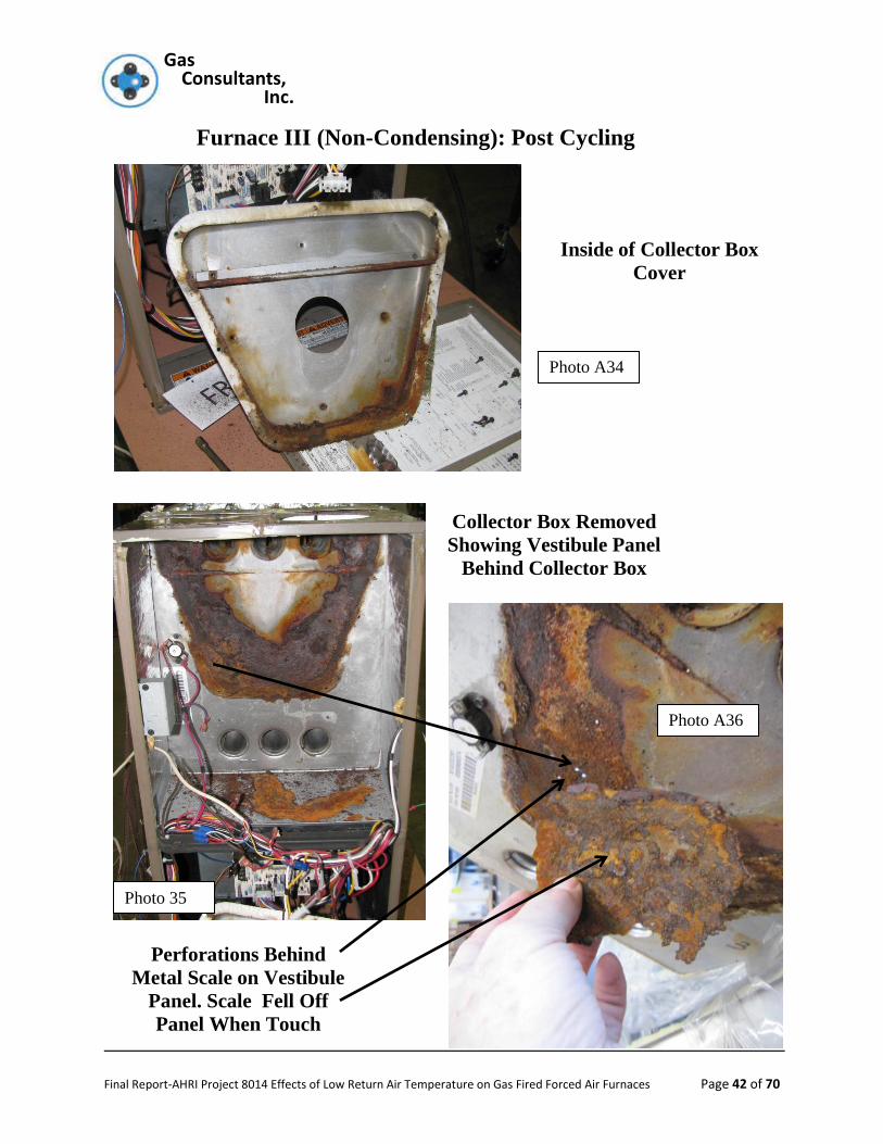
The header plate which separates the control compartment from the circulating air
side did show signs of corrosion on the circulating air side. An examination of the
flue gas side showed extensive damage with a large “flake” of “rust” covering
Gas Gas Consultants, Inc.
Final Report-AHRI Project 8014 Effects of Low Return Air Temperature on Gas Fired Forced Air Furnaces Page 27 of 70
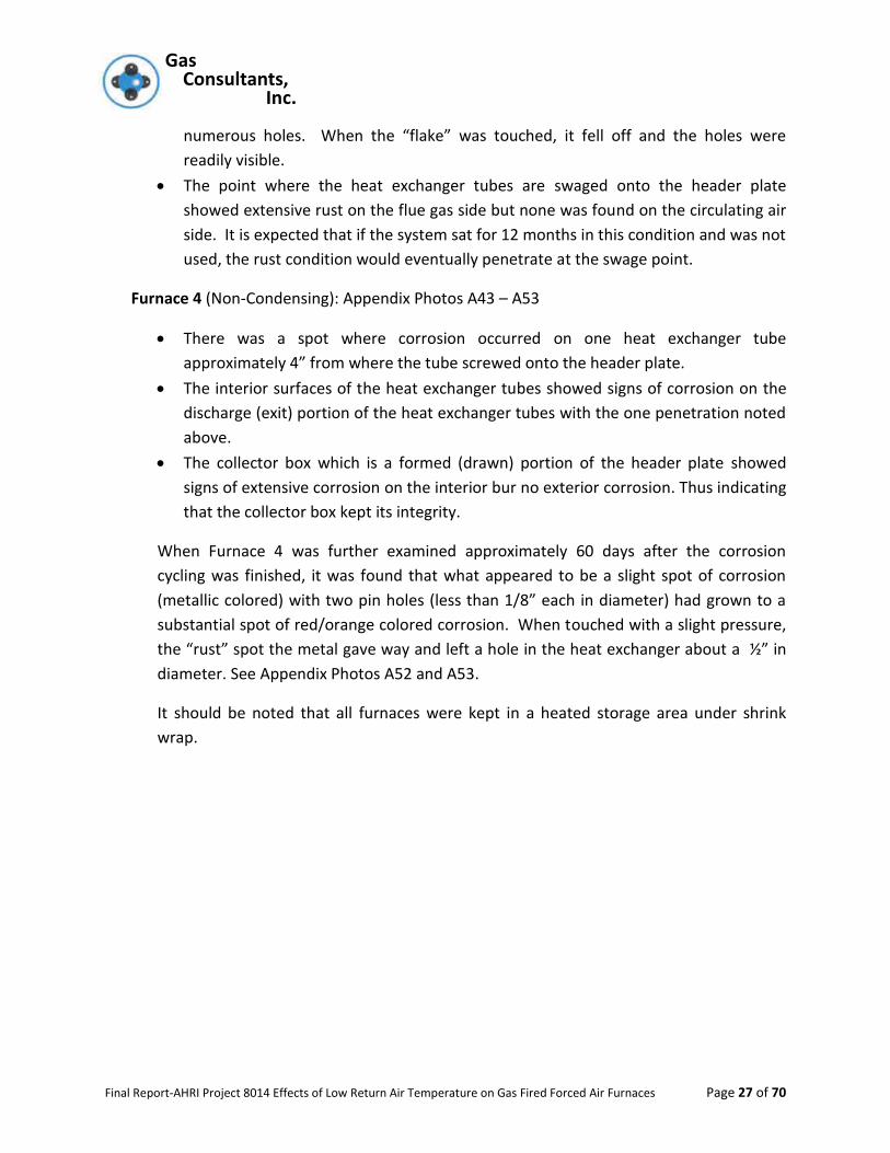
numerous holes. When the “flake” was touched, it fell off and the holes were
readily visible.
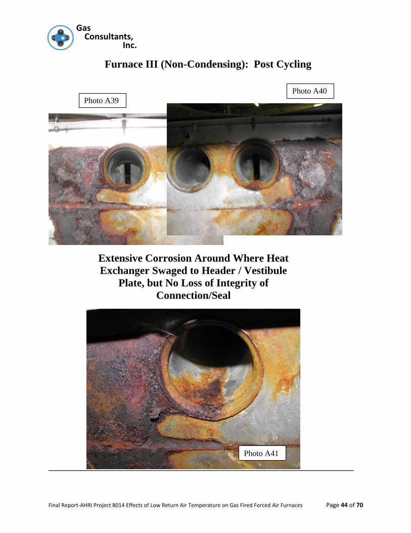
The point where the heat exchanger tubes are swaged onto the header plate
showed extensive rust on the flue gas side but none was found on the circulating air
side. It is expected that if the system sat for 12 months in this condition and was not
used, the rust condition would eventually penetrate at the swage point.
Furnace 4 (Non-Condensing): Appendix Photos A43 – A53
There was a spot where corrosion occurred on one heat exchanger tube
approximately 4” from where the tube screwed onto the header plate.
The interior surfaces of the heat exchanger tubes showed signs of corrosion on the
discharge (exit) portion of the heat exchanger tubes with the one penetration noted
above.
The collector box which is a formed (drawn) portion of the header plate showed
signs of extensive corrosion on the interior bur no exterior corrosion. Thus indicating
that the collector box kept its integrity.
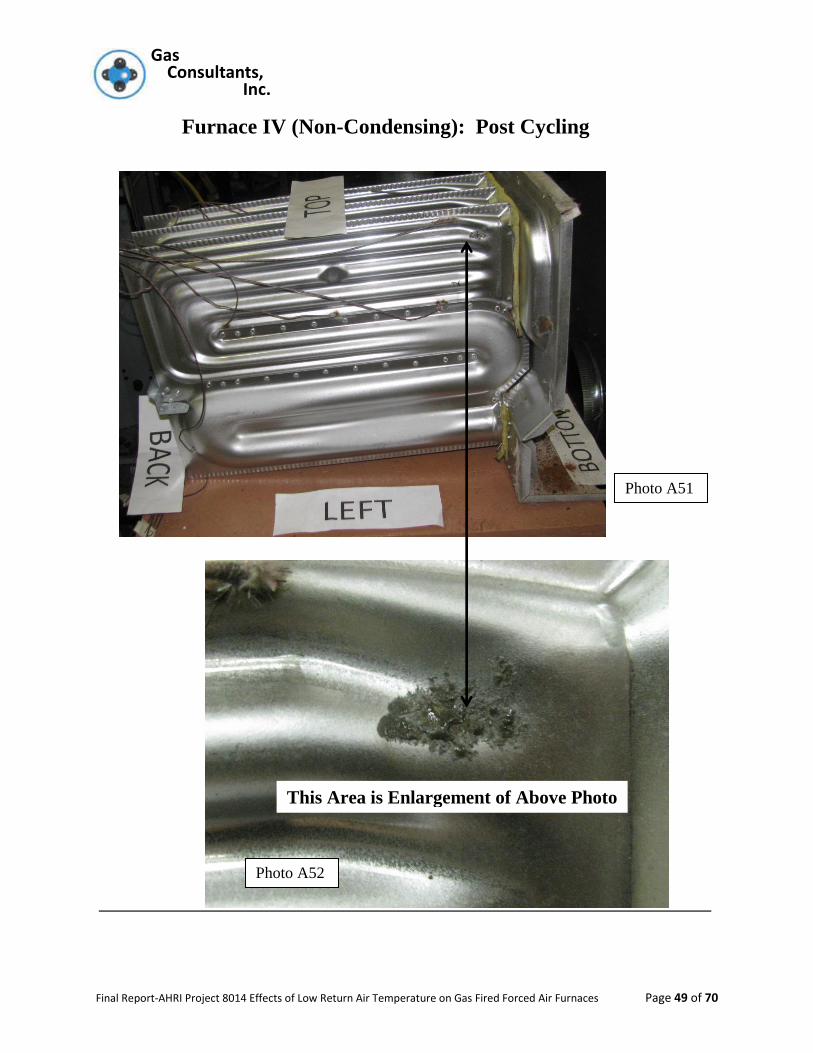
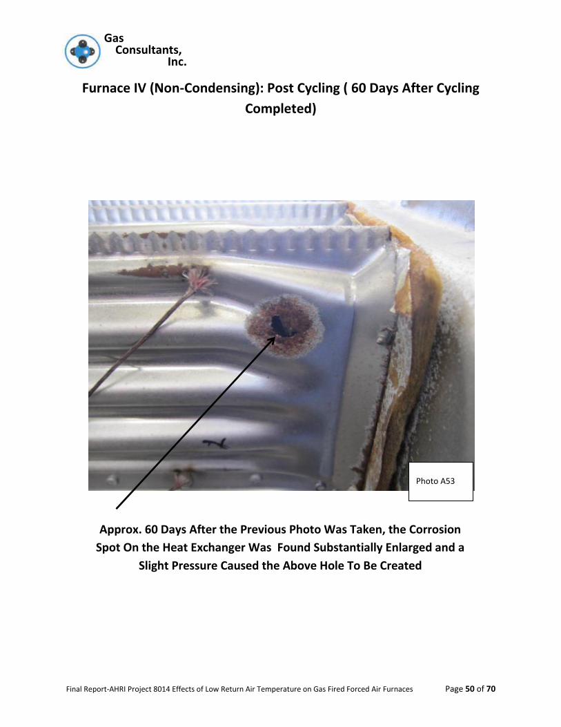
When Furnace 4 was further examined approximately 60 days after the corrosion
cycling was finished, it was found that what appeared to be a slight spot of corrosion
(metallic colored) with two pin holes (less than 1/8” each in diameter) had grown to a
substantial spot of red/orange colored corrosion. When touched with a slight pressure,
the “rust” spot the metal gave way and left a hole in the heat exchanger about a ½” in
diameter. See Appendix Photos A52 and A53.
It should be noted that all furnaces were kept in a heated storage area under shrink
wrap.
Gas Gas Consultants, Inc.
Final Report-AHRI Project 8014 Effects of Low Return Air Temperature on Gas Fired Forced Air Furnaces Page 28 of 70
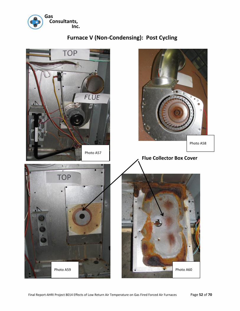
Furnace 5 (Non-Condensing): Appendix Photos A54– A68
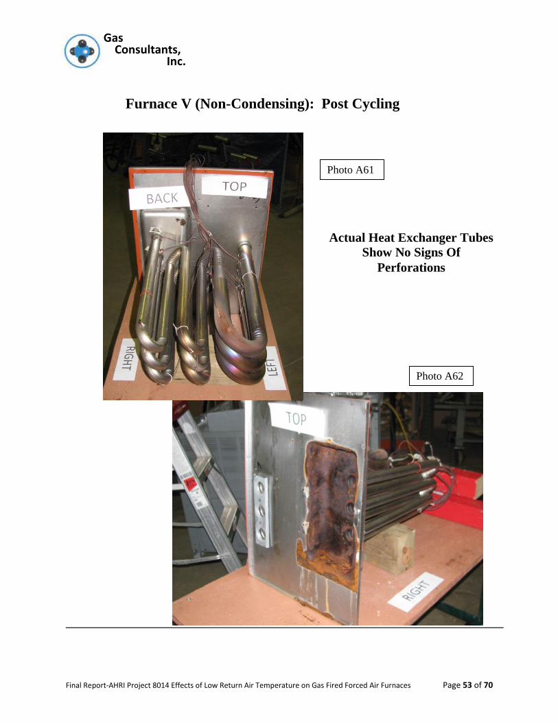
There were no signs of corrosion any metallic surfaces on of the heat exchanger
tubes on the circulating air side of the furnace.
The cover plate over the drawn collector box was examined and there was no
corrosion on the exterior surface and moderate on the flue gas side of the plate.
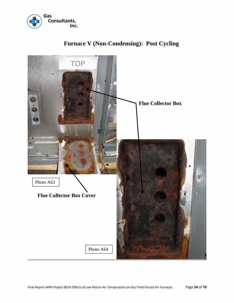
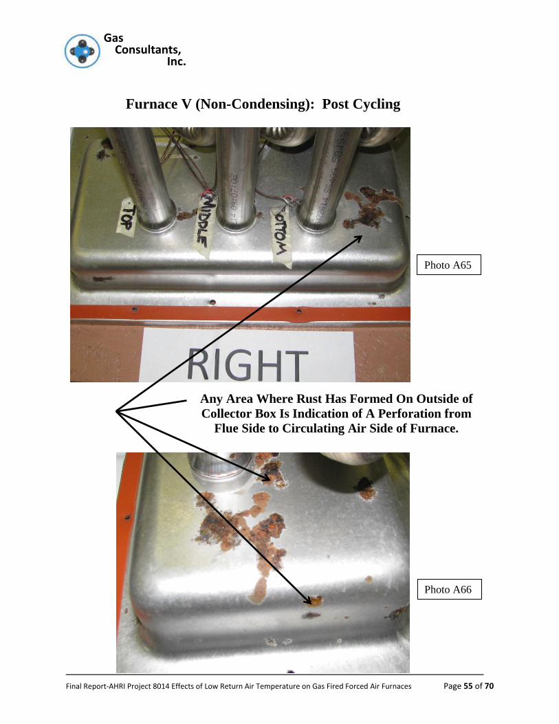
The drawn flue gas collector box had extensive corrosion on the interior of the box.
The exterior of the flue gas collector box had numerous points that exhibited
corrosion and these points did indicate penetration had occurred.
The collector box of Furnace 5 was re-examined after approximately 60 days and the
small penetrations noted above had grown into large voids in the metal. See
comparison photographs A67 and A68 for the substantial difference in penetration size.
As can be seen from the above, for non-condensing rated furnaces, the results of the
evaluation indicate that when such a furnaces is subjected to 45ºF return air and
tested under the conditions of this evaluation will lead to penetrations of the
sheet metal surface that form the boundary between the combustion gas side of
the furnaces and the circulating air side of the furnace. For condensing rated
furnaces when tested under the same method of test do not exhibit any adverse
issues of deterioration of the sheet metal components of the flue gas system.
Gas Gas Consultants, Inc.
Final Report-AHRI Project 8014 Effects of Low Return Air Temperature on Gas Fired Forced Air Furnaces Page 29 of 70
TEST EQUIPMENT AND LABATORY PROCEDURES
Gas Consultants, Inc. laboratory operates under an ISO 17025 laboratory accreditation from
LAB, an ILAC member. The Gas Consultants, Inc. quality control manual covers all aspects of
necessary operation, staff training, and, equipment calibration requirements to maintain an
EPA accreditation for Energy Star testing of gas along with the necessary surveillance by UL,
CSA and ETL to permit data generation for those three listing agencies including conducting
Z21.47 /CSA 2.3 Corrosion Testing of Heat Exchangers.
All calibration records of specific equipment used in this program are maintained in Gas
Consultants, Inc.’s database in Cleveland, Ohio.

Gas Gas Consultants, Inc.
Final Report-AHRI Project 8014 Effects of Low Return Air Temperature on Gas Fired Forced Air Furnaces Page 30 of 70
Appendix
Gas Gas Consultants, Inc.
Final Report-AHRI Project 8014 Effects of Low Return Air Temperature on Gas Fired Forced Air Furnaces Page 31 of 70
Layout of the Air Cooling System for Low Inlet Air
Temperature Study
2 of 4 Air Conditioning Systems Mounted
Above Air Duct Chambers
Insulation
Board
Over Air
Ductwork
Duct To Outdoor Air Supply
Photo A1
Photo A3
Photo A2

Gas Gas Consultants, Inc.
Final Report-AHRI Project 8014 Effects of Low Return Air Temperature on Gas Fired Forced Air Furnaces Page 32 of 70
Control Panel For Air
Temperature Control
Furnaces
III and IV
Insulated
Combustion Air
Ducts
Gas Meters Used To
Check Flows and
Operational Times
Photo A6
Photo A5
Photo A4

Gas Gas Consultants, Inc.
Final Report-AHRI Project 8014 Effects of Low Return Air Temperature on Gas Fired Forced Air Furnaces Page 33 of 70
Spiking Gas Cylinders
and Control
Apparatus
Photo A7
Photo A8
Photo A9
Cycle and Hour Counters and
Cycle Timers for Furnace
Monitoring

Gas Gas Consultants, Inc.
Final Report-AHRI Project 8014 Effects of Low Return Air Temperature on Gas Fired Forced Air Furnaces Page 34 of 70
Furnaces I
and II
Roof Top
Packaged
Furnace
(V)
Photo A10
Photo A11
Gas Gas Consultants, Inc.
Final Report-AHRI Project 8014 Effects of Low Return Air Temperature on Gas Fired Forced Air Furnaces Page 35 of 70
Furnace I (Condensing): Post Cycling
Photo A14
Photo A12
Photo A13
Gas Gas Consultants, Inc.
Final Report-AHRI Project 8014 Effects of Low Return Air Temperature on Gas Fired Forced Air Furnaces Page 36 of 70
Furnace I (Condensing): Post Cycling
Photo A15
Photo A17
Photo A16
Gas Gas Consultants, Inc.
Final Report-AHRI Project 8014 Effects of Low Return Air Temperature on Gas Fired Forced Air Furnaces Page 37 of 70
Furnace I (Condensing): Post Cycling
Photo A18
Photo A19
Photo A21
Photo A20

Gas Gas Consultants, Inc.
Final Report-AHRI Project 8014 Effects of Low Return Air Temperature on Gas Fired Forced Air Furnaces Page 38 of 70
Furnace II (Condensing): Post Cycling
Photo A25 Photo A24
Photo A23 Photo A22
Gas Gas Consultants, Inc.
Final Report-AHRI Project 8014 Effects of Low Return Air Temperature on Gas Fired Forced Air Furnaces Page 39 of 70
Furnace II (Condensing): Post Cycling
Photo A28
Photo A27
Photo A26

Gas Gas Consultants, Inc.
Final Report-AHRI Project 8014 Effects of Low Return Air Temperature on Gas Fired Forced Air Furnaces Page 40 of 70
Furnace II (Condensing): Post Cycling
Photo A31
Photo A30 Photo A29
Photo A31
Gas Gas Consultants, Inc.
Final Report-AHRI Project 8014 Effects of Low Return Air Temperature on Gas Fired Forced Air Furnaces Page 41 of 70
Furnace III (Non-Condensing): Post Cycling
Inlet to Combustion
Bower Assembly
View Through Collector
Box Cover Into Collector
Box
Photo A33
Photo A32
Gas Gas Consultants, Inc.
Final Report-AHRI Project 8014 Effects of Low Return Air Temperature on Gas Fired Forced Air Furnaces Page 42 of 70
Furnace III (Non-Condensing): Post Cycling
Inside of Collector Box
Cover
Collector Box Removed
Showing Vestibule Panel
Behind Collector Box
Perforations Behind
Metal Scale on Vestibule
Panel. Scale Fell Off
Panel When Touch
Photo 35
Photo A36
Photo A34
Gas Gas Consultants, Inc.
Final Report-AHRI Project 8014 Effects of Low Return Air Temperature on Gas Fired Forced Air Furnaces Page 43 of 70
Furnace III (Non-Condensing): Post Cycling
Perforation (Previous Page) Viewed
From The Circulating Air Side of
Vestibule or Header Panel
Photo A38
Photo A37
Gas Gas Consultants, Inc.
Final Report-AHRI Project 8014 Effects of Low Return Air Temperature on Gas Fired Forced Air Furnaces Page 44 of 70
Furnace III (Non-Condensing): Post Cycling
Extensive Corrosion Around Where Heat
Exchanger Swaged to Header / Vestibule
Plate, but No Loss of Integrity of
Connection/Seal
Photo A40
Photo A39
Photo A41

Gas Gas Consultants, Inc.
Final Report-AHRI Project 8014 Effects of Low Return Air Temperature on Gas Fired Forced Air Furnaces Page 45 of 70
Furnace III (Non-Condensing): Post Cycling
Photo A42
Gas Gas Consultants, Inc.
Final Report-AHRI Project 8014 Effects of Low Return Air Temperature on Gas Fired Forced Air Furnaces Page 46 of 70
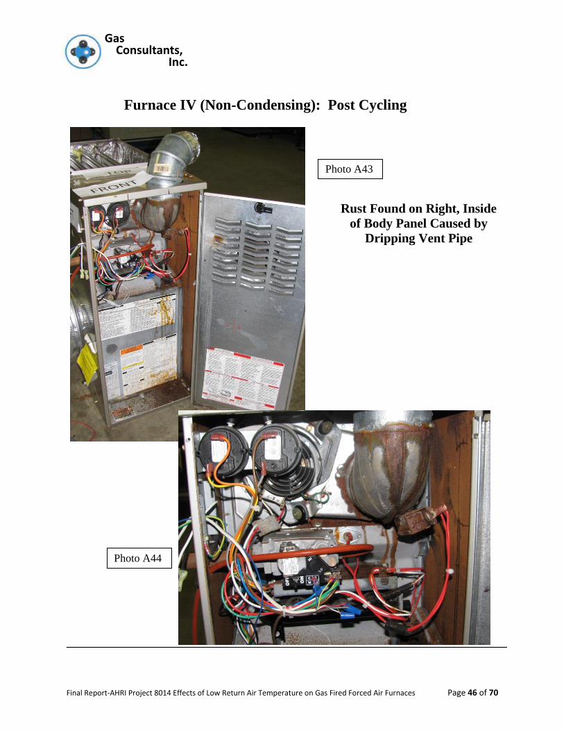
Furnace IV (Non-Condensing): Post Cycling
Rust Found on Right, Inside
of Body Panel Caused by
Dripping Vent Pipe
Photo A43
Photo A44
Gas Gas Consultants, Inc.
Final Report-AHRI Project 8014 Effects of Low Return Air Temperature on Gas Fired Forced Air Furnaces Page 47 of 70
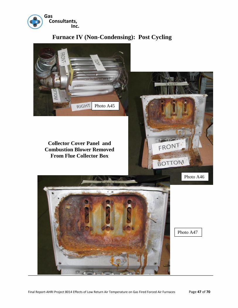
Furnace IV (Non-Condensing): Post Cycling
Collector Cover Panel and
Combustion Blower Removed
From Flue Collector Box
Photo A46
Photo A45
Photo A47
Gas Gas Consultants, Inc.
Final Report-AHRI Project 8014 Effects of Low Return Air Temperature on Gas Fired Forced Air Furnaces Page 48 of 70
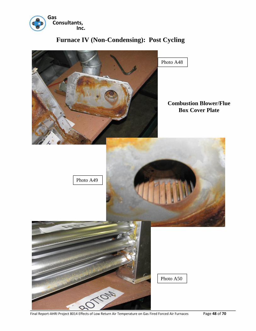
Furnace IV (Non-Condensing): Post Cycling
Combustion Blower/Flue
Box Cover Plate
Photo A50
Photo A49
Photo A48
Gas Gas Consultants, Inc.
Final Report-AHRI Project 8014 Effects of Low Return Air Temperature on Gas Fired Forced Air Furnaces Page 49 of 70
Furnace IV (Non-Condensing): Post Cycling
This Area is Enlargement of Above Photo
Photo A51
Photo A52
Gas Gas Consultants, Inc.
Final Report-AHRI Project 8014 Effects of Low Return Air Temperature on Gas Fired Forced Air Furnaces Page 50 of 70
Furnace IV (Non-Condensing): Post Cycling ( 60 Days After Cycling
Completed)
Approx. 60 Days After the Previous Photo Was Taken, the Corrosion
Spot On the Heat Exchanger Was Found Substantially Enlarged and a
Slight Pressure Caused the Above Hole To Be Created
Photo A53

Gas Gas Consultants, Inc.
Final Report-AHRI Project 8014 Effects of Low Return Air Temperature on Gas Fired Forced Air Furnaces Page 51 of 70
Furnace V (Non-Condensing): Post Cycling
Artificial Collector Box Placed Around Standard Vent Discharge
to Capture Flue Products and Discharge Outdoors
Photo A56
Photo A54
Photo A55
Gas Gas Consultants, Inc.
Final Report-AHRI Project 8014 Effects of Low Return Air Temperature on Gas Fired Forced Air Furnaces Page 52 of 70
Furnace V (Non-Condensing): Post Cycling
Flue Collector Box Cover
Photo A60
Photo A57
Photo A58
Photo A59
Gas Gas Consultants, Inc.
Final Report-AHRI Project 8014 Effects of Low Return Air Temperature on Gas Fired Forced Air Furnaces Page 53 of 70
Furnace V (Non-Condensing): Post Cycling
Actual Heat Exchanger Tubes
Show No Signs Of
Perforations
Photo A62
Photo A61
Gas Gas Consultants, Inc.
Final Report-AHRI Project 8014 Effects of Low Return Air Temperature on Gas Fired Forced Air Furnaces Page 54 of 70
Furnace V (Non-Condensing): Post Cycling
Flue Collector Box
Flue Collector Box Cover
Photo A63
Photo A64
Gas Gas Consultants, Inc.
Final Report-AHRI Project 8014 Effects of Low Return Air Temperature on Gas Fired Forced Air Furnaces Page 55 of 70
Furnace V (Non-Condensing): Post Cycling
Any Area Where Rust Has Formed On Outside of
Collector Box Is Indication of A Perforation from
Flue Side to Circulating Air Side of Furnace.
Photo A66
Photo A65

Gas Gas Consultants, Inc.
Final Report-AHRI Project 8014 Effects of Low Return Air Temperature on Gas Fired Forced Air Furnaces Page 56 of 70
Furnace V (Non-Condensing): Post Cycling
The Photo Above Was Taken 8 Days After Cycling Was
Finished. Very Small Holes Present.
The Photo Below Was Taken of Same Spot After 6o
Days in Storage After Cycling Was Completed.
Photo A68
Photo A67

Gas Gas Consultants, Inc.
Final Report-AHRI Project 8014 Effects of Low Return Air Temperature on Gas Fired Forced Air Furnaces Page 57 of 70
Gas Gas Consultants, Inc.
Final Report-AHRI Project 8014 Effects of Low Return Air Temperature on Gas Fired Forced Air Furnaces Page 58 of 70
Gas Gas Consultants, Inc.
Final Report-AHRI Project 8014 Effects of Low Return Air Temperature on Gas Fired Forced Air Furnaces Page 59 of 70
Gas Gas Consultants, Inc.
Final Report-AHRI Project 8014 Effects of Low Return Air Temperature on Gas Fired Forced Air Furnaces Page 60 of 70
Gas Gas Consultants, Inc.
Final Report-AHRI Project 8014 Effects of Low Return Air Temperature on Gas Fired Forced Air Furnaces Page 61 of 70
Gas Gas Consultants, Inc.
Final Report-AHRI Project 8014 Effects of Low Return Air Temperature on Gas Fired Forced Air Furnaces Page 62 of 70
Gas Gas Consultants, Inc.
Final Report-AHRI Project 8014 Effects of Low Return Air Temperature on Gas Fired Forced Air Furnaces Page 63 of 70
Gas Gas Consultants, Inc.
Final Report-AHRI Project 8014 Effects of Low Return Air Temperature on Gas Fired Forced Air Furnaces Page 64 of 70

Gas Gas Consultants, Inc.
Final Report-AHRI Project 8014 Effects of Low Return Air Temperature on Gas Fired Forced Air Furnaces Page 65 of 70
Gas Gas Consultants, Inc.
Final Report-AHRI Project 8014 Effects of Low Return Air Temperature on Gas Fired Forced Air Furnaces Page 66 of 70
Gas Gas Consultants, Inc.
Final Report-AHRI Project 8014 Effects of Low Return Air Temperature on Gas Fired Forced Air Furnaces Page 67 of 70
Gas Gas Consultants, Inc.
Final Report-AHRI Project 8014 Effects of Low Return Air Temperature on Gas Fired Forced Air Furnaces Page 68 of 70
Gas Gas Consultants, Inc.
Final Report-AHRI Project 8014 Effects of Low Return Air Temperature on Gas Fired Forced Air Furnaces Page 69 of 70

Gas Gas Consultants, Inc.
Final Report-AHRI Project 8014 Effects of Low Return Air Temperature on Gas Fired Forced Air Furnaces Page 70 of 70