Embed Size (px)
Citation preview

Final Report on
Study of
Alternative Tank Materials Docket 11728 by
Joan Muellerleile and Rod Osborne
Battelle
Mark Greenwood
Composite Solutions Consultants
To
Propane Education
& Research Council
1140 Connecticut Ave. NW, Suite 1075
Washington, DC 20036
June 2006
Final Report to
The Propane Education & Research Council (PERC)
on
Study of Alternative Tank Materials
(PERC Docket Number 11728)
June 2006
by
Joan Muellerleile Rod Osborne
BATTELLE
and
Mark Greenwood COMPOSITE SOLUTIONS CONSULTANTS, INC.

Notice
Battelle does not engage in research for advertising, sales promotion, or endorsement of our clients' interests including raising investment capital or recommending investments decisions, or other publicity purposes, or for any use in litigation. Battelle endeavors at all times to produce work of the highest quality, consistent with our contract commitments. However, because of the research and/or experimental nature of this work the client undertakes the sole responsibility for the consequence of any use or misuse of, or inability to use, any information, apparatus, process or result obtained from Battelle, and Battelle, its employees, officers, or Directors have no legal liability for the accuracy, adequacy, or efficacy thereof.

BATTELLE iii PERC Docket 11728 Alternative Tank Materials
Acknowledgements
The authors wish to express their appreciation to the individuals who contributed to the successful completion of this program. The authors appreciate the support of Mr. Robert Nicholson of Eastern Propane for his suggestions and guidance regarding the issues of underground propane tanks. The authors also wish to acknowledge the support of Mr. Maurice Ryman and Mrs. Jackie Ryman of LP Cylinder Service for their general information regarding steel underground propane tanks. In addition, the authors appreciate the comments of the many propane marketers who wished to remain anonymous. Their experiences and comments were equally valuable.

BATTELLE iv PERC Docket 11728 Alternative Tank Materials
Executive Summary Steel pressure vessels have been used for decades for propane storage and transportation. Aboveground storage tanks range from one hundred to tens of thousands of gallons. In the past several years, there has been increasing interest in burying tanks at both residential and commercial customer sites. Underground propane tanks are thus becoming increasingly popular as alternatives to standard aboveground tanks. While there are safety advantages to burying tanks, such as eliminating fire exposure and removing them as traffic hazards, the main reason is for aesthetics, as a buried tank is out of sight, except for the access lid. In the past five years, due to increasing worldwide demand, especially in Asia, steel prices have tripled, from just over $200 per ton in 2001 to an expected $650 per ton in mid-2006 (Ostroff, 2006 and Rey, 2004a). This tremendous increase in steel costs, coupled with the necessity and expense of corrosion protection and recommended periodic inspection of the corrosion protection system (May, 2005 and Underwriters’ Laboratory, 2002), has raised interest in the propane industry for alternative materials of construction for underground storage tanks. In response to this situation, the Propane Education & Research Council (PERC) has begun to investigate alternative materials for underground propane tanks. This report documents the results of a feasibility study of this use of alternative materials. The project developed preliminary designs for composite tanks for underground service. The designs were based on previous experiences with underground petroleum storage tanks, considering tank design pressure, cyclic pressures due to temperature and filling, and soil loading. This feasibility design approach for underground composite propane tanks for residential use is based upon a combination of American Society of Mechanical Engineers (ASME) Section X (Fiber-Reinforced Plastic Pressure Vessels) for the primary pressure vessel design, and American Water Works Association (AWWA) Manual of Water Supply Practices M45 (Fiberglass Pipe Design) to account for the buried installation of the tank (ASME, 2004; AWWA, 2005). The design assumes a filament-wound tank using fiberglass and a good quality isophthalic resin for adequate performance in order to help minimize the cost of the tank. The approximate dimensions and marketers’ costs for 250 gallon and 1000 gallon composite tanks, based upon this feasibility design, are shown in Table ES-1. For comparison, estimated steel tank dimensions and marketers’ costs are also shown in Table ES-1.

BATTELLE v PERC Docket 11728 Alternative Tank Materials
Table ES-1. Estimated Underground Tank Costs - Steel and Composite Steel
250 gallon Composite 250 gallon
Steel 1000 gallon
Composite 1000 gallon
Weight 484 lbs 260 lbs 1741 lbs 970 lbs Total length 5 feet 5 feet 13 feet 13 feet Diameter 32 inches 32 inches 41 inches 41 inches Thickness 0.20 inch 0.42 inch 0.25 inch 0.51 inch Cost (F.O.B. plant site)
$800 (tank) + $ 75 (1 anode) $875
$1000 (appurtenances in head) $1125 (appurtenances in side wall)
$2075 (tank) + $ 150 (2 anodes) $2225
$2400 (appurtenances in head) $2550 (appurtenances in side wall)
Based upon the feasibility design outlined in this final report, the rough-estimate first cost of the composite tank is higher than that for the steel tank by $200 to $300. Note, however, that the costs for the steel tank in the above table do not include the cathodic protection monitoring costs over the service life of the tank. As will be described in the body of the report, these costs are estimated to be on the order of $550. If these costs for periodic inspections are included, the total life-cycle cost of the composite tank may compare more favorably to the steel tank. Thus, this preliminary cost analysis shows that such alternative material underground tanks are potentially competitive with steel construction from a life cycle cost standpoint. The ASME design code (Boiler & Pressure Vessel Code, Section X) has more restrictive constraints for vessels that have both external and internal loads, such as when an empty tank is first buried and then filled. While the Section X constraint is intended for extensive load reversals, a propane tank will typically experience one load reversal during the initial burial followed by filling. The relaxation of this restriction could reduce the design margin, and therefore the manufacturing costs, of the composite tank for underground propane use. NFPA 58 - Liquefied Petroleum Gas Code (NPFA, 2004a) governs the installation of propane systems. Section 5.2.1.1 (LP-Gas Equipment and Appliances, Containers, General) requires that containers be designed in accordance with the regulations of the ASME Boiler and Pressure Vessel Code, Section VIII, “Rules for the Construction of Unfired Pressure Vessels.” Section VIII allows metallic materials only. As mentioned above, pressure vessels fabricated from composite materials are addressed in Section X. Therefore, NFPA 58 would have to be modified to allow Section X-designed (composite) vessels in addition to Section VIII-designed (metallic) vessels. A to-be-proposed second phase of this project will involve a refined prototype design, utilizing support from a manufacturer of composite cylinders and tanks.
Table of Contents
Section Page
Executive Summary ...............................................................................................................iv
Introduction and Background ................................................................................................1
Underground Composite Propane Tank Design Overview ...................................................6
Detailed Tank Design Process ...............................................................................................9
Proposed Phase II Feasibility Design Refinement.................................................................11
Summary and Conclusions ....................................................................................................13
References..............................................................................................................................14
Tables and Figures
Page
Table ES-1. Estimated Underground Tank Costs - Steel and Composite .............................v
Figure 1. Schematic of an underground steel propane tank cathodically protected using a sacrificial anode of either magnesium powder or a magnesium rod .....................................3
Figure 2. Installation of Cathodic Protection System on Underground Propane Tank .........4
Table 1. Estimated Underground Tank Costs - Steel and Composite....................................7

BATTELLE 1 PERC Docket 11728 Alternative Tank Materials
Introduction and Background Underground propane tanks are becoming increasingly popular as alternatives to standard aboveground tanks. While underground tanks may have safety advantages, such as reduced exposure to fires and removing the tank from traffic areas, the main reason for burying propane tanks is for aesthetics, as a buried tank is out of sight, except for the access lid. The environmentally nontoxic nature of propane also eliminates concerns regarding potential soil and water contamination (Sympson, 2005 and Advocate, 2006), unlike underground storage tanks for other fuels such as gasoline and fuel oil. Without proper corrosion protection, however, underground steel tanks are susceptible to corrosion and potential problems stemming from corrosion issues, such as a propane leak at a site in the tank wall that has corroded (May, 2005; Nicholson, 2005; Eastern Propane, 2004; NPGA,1991; and NPGA, 1994). Corrosion is an electrochemical process involving the flow of electrical current and oxidation in a cell. The corrosion cell contains the following primary components: the anode (one area on a tank wall), from which electrical current flows and oxidation (corrosion) occurs; the cathode (another area on the tank wall), to which the electrical current from the anode flows and reduction occurs; and an electrolyte, which is a medium such as water or soil that conducts ionic current. Corrosion will occur if an electrical potential exists between the anode and cathode and oxygen is present. From the chemical standpoint, corrosion is the formation of iron oxide, or rust, by the combination of positively–charged iron ions breaking away from the anode with oxygen, water, and other negatively-charged ions (Eastern Propane, 2004; Heidersbach, 1987; May, 2005; and NPGA, 1994). Voltage differences exist on the surface of an underground steel tank. These can be caused by, for example, the presence of impurities, or by lattice defects that may be caused by strain on the steel. These small differences in voltage cause DC current to flow from one localized area (anode) on the tank surface to another (cathode) through the soil (electrolyte). The extent of corrosion is a function of the amount of current flowing in these localized corrosion cells on the tank surface, and how long the localized corrosion cell locations remain constant with time (Brown and LeMay, 1981; Heidersbach, 1987; May, 2005; Mesa, 2005; Perry and Chilton, 1973; and Schmoldt, 2003). The rate of corrosion is affected by the conductivity of the electrolyte. The conductivity of the soil surrounding an underground steel tank, for example, is affected by the pH of the soil, moisture content, and the presence in the soil of other contaminants such as salts and other minerals. The presence of these contaminants accelerates the rate of corrosion (Brown and LeMay, 1981; Heidersbach, 1987; NPGA, 1994; and Schmoldt, 2003). Three common methods currently practiced to protect underground steel structures such as tanks from corrosion are a) a protective organic coating; b) cathodic protection using a sacrificial anode (passive system); and c) cathodic protection using an impressed-current anode (active system), which involves the direct application of DC current to the steel surface. As the impressed-current anode method is most commonly used in conjunction with extremely large structures such as pipelines and not the small tanks discussed in this work, it will not be discussed further here (Heidersbach, 1987; NPGA, 1994; and Schmoldt, 2003).

BATTELLE 2 PERC Docket 11728 Alternative Tank Materials
The protective organic coating is typically applied by the tank manufacturer. Types of coatings include epoxies, enamels, phenolics, urethanes, and mastics. Referring to the above description of corrosion, the purpose of the coating is to protect the steel tank from exposure to the electrolyte. If the steel tank were completely insulated from the electrolyte environment, then the current could not flow from the anode to the cathode, and corrosion would not occur. Hence, if a corrosion protective coating could be applied perfectly and then transported and installed underground with no holidays (void areas), scratches, or other imperfections, then protection would be complete, and cathodic protection would be unnecessary. However, as no such perfect coating exists, cathodic protection is the necessary complement to coating application for underground corrosion protection. The coating reduces the level of overall cathodic protection required for the tank, but does not eliminate it, as corrosion will concentrate at any holidays, scratches, or other imperfections involving exposure of the steel tank surface, and thus be that much more severe at those spots than if the tank were uncoated. A coated tank with coating imperfections buried without cathodic protection can be worse than burying an uncoated tank without cathodic protection because of the corrosion concentration at the imperfections. Additionally, coatings are difficult to monitor once the tank is installed underground (Brown and LeMay, 1981; Heidersbach, 1987; Mesa, 2005; Nicholson, 2005; NPGA, 1991; Perry and Chilton, 1973; and Schmoldt, 2003). Cathodic protection involves the use of a metal that is anodic relative to the metal desired to be rendered cathodic (steel for the case of the underground tank) in order to protect the latter from corrosion. Magnesium, zinc, and aluminum alloys are commonly used as sacrificial alloys. Magnesium is most typically used for sacrificial anodes in buried soil applications. Cathodic protection controls corrosion by concentrating the oxidation reaction at the anode and thus suppressing corrosion at the cathode of the same cell. An electric circuit (such as an insulated wire) connects the sacrificial anode and the cathode. Cathodic protection of an underground tank is illustrated below in Figure 1 using either magnesium powder or a magnesium rod as the sacrificial anode. Figure 2 shows the actual installation of an underground propane tank, with the cathodic protection system being attached to the tank (Brown and LeMay, 1981; Heidersbach, 1987; NPGA, 1994; and Schmoldt, 2003). The ideal full implementation of current recommendations and practice regarding corrosion protection and monitoring for underground steel tanks is an involved process, requiring careful and diligent tank preparation (protective coating), installation, and monitoring. There are opportunities for steps to be missed and situations in which the marketer does not have control over the process. These issues have been observed by and in the propane industry. An example is the situation in which the marketer has delivered the underground tank to an installation site, and the building contractor has agreed to provide the hole for the tank and to contact the marketer when the hole is ready. The contractor may decide for the sake of convenience to simply bury the tank without the marketer present. The marketer then does not know whether or to what degree correct tank installation and cathode attachment procedures were followed, or if the installation were properly backfilled (NACE, 2002a; Nicholson, 2005; and Ryman, 2005).

BATTELLE 3 PERC Docket 11728 Alternative Tank Materials
Figure 1. Schematic of an underground steel propane tank cathodically protected using a sacrificial anode of either magnesium powder or a magnesium rod. To our knowledge, no formal industry specification exists outlining the protective coating minimum requirements, such as thickness necessary to protect the tank against corrosion. Long-term assessment over a period of decades reported by one marketer indicates that a uniform coating with a minimum thickness of 8-9 mils is necessary to protect against corrosion. The new tanks from the manufacturers have required both uniform thickness and holiday and other defect inspections. These inspections have sometimes resulted in the return of the tanks because the coatings contained too many imperfections, insufficient coating thickness around the tank (the area around the tank legs, for example, is particularly susceptible), or both. One marketer’s solution for years has been to remove the tank manufacturers’ original coatings and prepare the tank surface to a near white blast for better coating adhesion prior to applying the coating, and then re-apply a coating. The marketer has now implemented coating specification requirements to the tank manufacturers, and if the tanks do not meet these requirements, they are returned to the manufacturers. He uses cathodic protection to supplement the protection provided by the coating, and monitors the cathodic protection (Nicholson, 2005; Ryman, 2005).

BATTELLE 4 PERC Docket 11728 Alternative Tank Materials
Figure 2. Installation of Cathodic Protection System on Underground Propane Tank Another marketer is performing thickness and holiday inspections as part of his tank preparation procedure. As he does not have the option to either recoat tanks with coatings that do not fully meet his criteria or present the manufacturers with requirements for tank acceptance, he installs the tanks that are at least minimally acceptable, and uses cathodic protection to protect the deficiencies from corrosion. He monitors the cathodic protection, and adds another sacrificial anode if the potential drops below –0.85V. If addition of another anode does not resolve the problem, then the tank requires excavation for inspection. There are no definitive recommendations and practices regarding cathodic protection monitoring of an underground steel tank. A potential reading of at least –0.85 V versus a copper/copper sulfate reference cell is the most commonly-used criterion to determine that the tank is cathodically protected (Eastern Propane, 2004; May, 2005; NACE, 2002a; NACE, 2002b; NPGA, 1991; NPGA, 1994; Schmoldt, H., 2003; and UL, 2002). However, there does not appear to be a definitive statement regarding monitoring timing. For example, NPGA (1994) states that the anode condition should to be assessed on a “periodic basis,” without specifying frequency. NACE Standards (2002a and 2002b) both state that field-installed galvanic (sacrificial anode) cathodic protection systems should be monitored annually. Corrosion experts also advocate annual cathodic protection monitoring for field-installed systems (May, 2005 and Schmoldt, H., 2003). Monitoring of cathodic protection by marketers appears to vary from periodic (from one

BATTELLE 5 PERC Docket 11728 Alternative Tank Materials
to three years or at occasional intervals) to not at all. The cost of performing these inspections has been cited as a concern. The other side of the issue is that without monitoring, there is no way of knowing whether the tank is adequately protected from corrosion. The issue of frequency of monitoring remains an open question at this time. Monitoring is thus another situation regarding underground steel tanks where crucial maintenance steps can be at risk of being missed depending upon the interpretation of “sufficient monitoring.” In addition to concerns regarding cathodic protection and cathodic protection monitoring of steel underground tanks, steel raw material costs have dramatically increased in response to surging worldwide demand. Additionally, the costs involved with underground installation, cathodic protection, and monitoring result in the price of procuring and installing underground steel tanks rising even higher (Sympson, 2005 and Ryman, 2005). In response to this situation, the Propane Education & Research Council (PERC) has begun to investigate alternative materials for underground propane tanks. Composites can offer a number of significant advantages over standard steel for cylinder applications. Composite resistance to corrosion, especially for underground applications, is particularly attractive, as it eliminates the need for cathodic protection and monitoring of the tank. Its lighter weight also provides ease of handling for transport, installation, and removal compared to its steel counterparts (Rey, 2004b).

BATTELLE 6 PERC Docket 11728 Alternative Tank Materials
Underground Composite Propane Tank Design Overview This feasibility design approach for underground composite propane tanks for residential use is based upon a combination of the ASME Boiler and Pressure Vessel Code, Section X (Fiber-Reinforced Plastic Pressure Vessels) (ASME, 2004) for the primary design, and AWWA Manual of Water Supply Practices M45 (Fiberglass Pipe Design) (AWWA, 2005) to account for the buried installation of the tank. There is no explicit prohibition for underground tanks designed using ASME Section X. The ASME Section X design is to the Class II tank (Section B), as the Class I tank has significant limitations such as a design strain limit of 0.1%, corresponding to a safety design factor of 15. A tank class refers to a production tank (Class II) versus a prototype tank (Class I). More specifically, the primary ASME Section X design basis generally follows Article RD-11 (Mandatory Design Rules for Class II Vessels). To account for the buried installation, AWWA M45 is used for the analysis and prediction of installation design, loads, buckling resistance, and deflections. AWWA M45 reflects the actual loading from the installed condition, and accounts for the added stability provided by the presence of the soil. Performance requirements are defined by ASME Section X Article RT-2 (Design and Procedure Qualification Test Requirements for Class I Vessels). To help minimize the cost of the tank, this design assumes a filament-wound tank using fiberglass and a good quality isophthalic resin for adequate performance. The original proposal for this project proposed identifying five candidate alternate material systems for propane tanks. ASME Section X specifically lists a number of approved resins and fibers. These components were initially evaluated for alternate material system candidates. On the bases of providing adequate performance while minimizing cost, the number of candidates was quickly reduced to isophthalic polyester with glass fiber reinforcement. If another candidate system with a component not on the approved list were utilized, the process necessary to attain Section X approval for the component would require several years (Brown, 2005). On that basis, other candidate system resin and fiber components outside of the ASME Section X approved list were not considered for this feasibility design. In order to reduce manufacturing costs, the basic feasibility design also utilizes hemispherical end caps and polar valves. Estimated costs are also listed for appurtenances installed in the sidewall as is typically the case for underground steel tanks, as opposed to the polar location. Key assumptions for this feasibility design include:
- Primary design is ASME Section X, with the buried installation condition given by AWWA M45
- Maximum allowable operating pressure is 250 psi used to design tank (internal pressure design limit)
- AWWA M-45 buried operating conditions (listed below) determined an external pressure of order of 5 psi. No artificial external pressure criteria were applied.
- Buried operating conditions using AWWA M-45: o burial depth from 24 inches to 48 inches o water table at ground surface (worst-case scenario) o H-10 (medium duty truck) traffic load without slab above tank (8000 lbs on
dual rear tires with a ground contact area of 10 inches by 20 inches
BATTELLE 7 PERC Docket 11728 Alternative Tank Materials
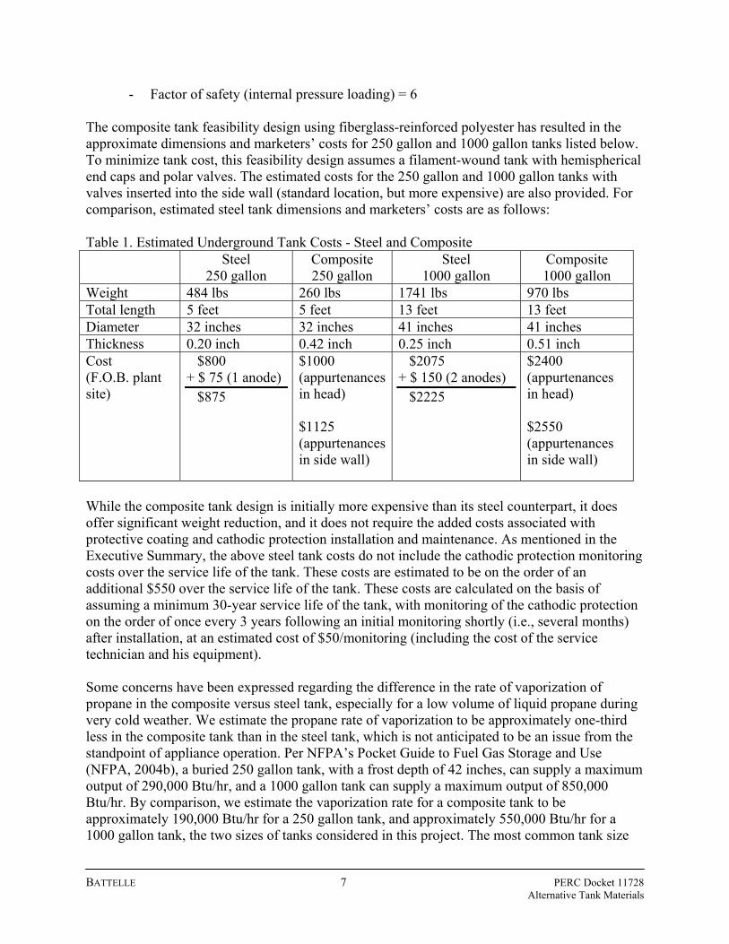
- Factor of safety (internal pressure loading) = 6 The composite tank feasibility design using fiberglass-reinforced polyester has resulted in the approximate dimensions and marketers’ costs for 250 gallon and 1000 gallon tanks listed below. To minimize tank cost, this feasibility design assumes a filament-wound tank with hemispherical end caps and polar valves. The estimated costs for the 250 gallon and 1000 gallon tanks with valves inserted into the side wall (standard location, but more expensive) are also provided. For comparison, estimated steel tank dimensions and marketers’ costs are as follows: Table 1. Estimated Underground Tank Costs - Steel and Composite Steel
250 gallon Composite 250 gallon
Steel 1000 gallon
Composite 1000 gallon
Weight 484 lbs 260 lbs 1741 lbs 970 lbs Total length 5 feet 5 feet 13 feet 13 feet Diameter 32 inches 32 inches 41 inches 41 inches Thickness 0.20 inch 0.42 inch 0.25 inch 0.51 inch Cost (F.O.B. plant site)
$800 + $ 75 (1 anode) $875
$1000 (appurtenances in head) $1125 (appurtenances in side wall)
$2075 + $ 150 (2 anodes) $2225
$2400 (appurtenances in head) $2550 (appurtenances in side wall)
While the composite tank design is initially more expensive than its steel counterpart, it does offer significant weight reduction, and it does not require the added costs associated with protective coating and cathodic protection installation and maintenance. As mentioned in the Executive Summary, the above steel tank costs do not include the cathodic protection monitoring costs over the service life of the tank. These costs are estimated to be on the order of an additional $550 over the service life of the tank. These costs are calculated on the basis of assuming a minimum 30-year service life of the tank, with monitoring of the cathodic protection on the order of once every 3 years following an initial monitoring shortly (i.e., several months) after installation, at an estimated cost of $50/monitoring (including the cost of the service technician and his equipment). Some concerns have been expressed regarding the difference in the rate of vaporization of propane in the composite versus steel tank, especially for a low volume of liquid propane during very cold weather. We estimate the propane rate of vaporization to be approximately one-third less in the composite tank than in the steel tank, which is not anticipated to be an issue from the standpoint of appliance operation. Per NFPA’s Pocket Guide to Fuel Gas Storage and Use (NFPA, 2004b), a buried 250 gallon tank, with a frost depth of 42 inches, can supply a maximum output of 290,000 Btu/hr, and a 1000 gallon tank can supply a maximum output of 850,000 Btu/hr. By comparison, we estimate the vaporization rate for a composite tank to be approximately 190,000 Btu/hr for a 250 gallon tank, and approximately 550,000 Btu/hr for a 1000 gallon tank, the two sizes of tanks considered in this project. The most common tank size

BATTELLE 8 PERC Docket 11728 Alternative Tank Materials
of 500 gallons would have an estimated maximum output of 300,000 Btu/hr. Except for the 250 gallon tank, the vaporization rate for a composite tank is estimated to be far above the typical residential usage for a furnace/boiler of 80,000 Btu/hr, a water heater of 40,000 Btu/hr, and a range of 60,000 Btu/hr. Thus, the difference in the heat of vaporization of propane in a composite versus a steel tank at low liquid volumes in very cold weather is not anticipated to be a problem.
Additional concerns have been raised regarding the chemical resistance of the composite tank to constituents and additives in the propane, such as ethyl mercaptan or methanol. Although exposure at 100% concentration is not recommended for either additive, communication with an isophthalic resin supplier stated that no problem is anticipated with propane and its additives, as the company had examined isophthalic polyester and propane. Addressing the specific issue about potentially elevated levels of ethyl mercaptan from the normal level of approximately 100 ppm to, in an extreme case, of 10,000 ppm, the technical contact anticipated no problem, as this concentration is only 1% ethyl mercaptan. Other constituents in “off-specification” propane, such as water, higher levels of propylene, butane, heavy ends (such as compressor oils), and high levels of methanol (thousands of parts per million) are also not anticipated to attack the glass fibers or the isophthalic polyester resin. Furthermore, isophthalic polyester has successfully been used for decades in underground fuel oil and gasoline applications. Finally, a commercial partner being considered for a Phase II effort uses polyethylene (either as low- or high-density (LDPE or HDPE)) as a liner material, and the material compatibility of both LDPE and HDPE with the above constituents and additives is excellent. A HDPE liner is has been used in a commercially-available propane cylinder in Europe for many years. The issue of chemical resistance of the composite tank to propane and its additives and constituents will be considered in Phase II of this work (Amoco Chemical Company, 1988; Landmark Products; Pearson, Pinard, and Greenwood, 1978; Plastics Design Library, 1994).

BATTELLE 9 PERC Docket 11728 Alternative Tank Materials
Detailed Tank Design Process The design limits for Class II vessels are given in ASTM Section X Subarticle RD-1120 (Design Limitations). RD-1120 states the limit of the product of internal pressure (psig) and inside diameter (inch) must be less than 14,400 pounds/inch. Therefore, for 250 psig internal pressure design, the inside diameter limit is 57.6 inches. RD-1120 also states that the maximum external pressure for a Class II vessel is 15 psi. Subarticle RD-1140 (Loadings) specifies that loadings requiring consideration as part of the design are as stipulated in the general Subarticle RD-120 (Loadings). On the basis of RD-120, the four imposed design loading conditions determined to require design consideration are a) internal pressure of 250 psig; b) external pressure as defined by buried installation requirements with burial depth between 24 to 48 inches; c) assumed water table at grade (at ground surface) for worst-case buckling condition; and d) assumed H-10 traffic load (8000 pounds on dual rear tires with a ground contact area of 10 inches by 20 inches) above tank without a slab for the feasibility study. Subarticle RD-1160 (Laminate Composition) specifies that tank laminate compositions that qualify as acceptable for Class II vessels are restricted to those made from resin and fiber specified in subarticles RM-120 (Resin System) and RM-100 (Fiber System), respectively. The resin and reinforcement selected for this feasibility study are a good quality isophthalic polyester, and glass fiber of Type E (E denotes electrical grade, which is a calcium alumino-borosilicate composition with low alkali oxide content) or E-CR (a calcium alumino-silicate variant of the E-glass composition with better chemical resistance (CR) than E-glass) composition, respectively (Watson and Raghupathi, 1987). These were chosen because they provide adequate performance while minimizing cost. As mentioned previously, ASME Section X lists several specific resins and fibers that have been approved for composite pressure vessel design. If another candidate system with a component not on the approved list were utilized, the process required to attain Section X approval for the component would take at least several years (Brown, 2005). This feasibility design was assumed to be a standard filament wound pressure vessel construction with 54.75° reinforcement orientation and standard composition with 75% glass reinforcement by weight. This is a good initial approximation that mimics the overall thickness of the final tank design for any tank design of any filament-winding process, as long as the component compositions are the same. Article RD-12 (Laminate Stiffness Coefficients) is not used for this feasibility study. The material properties are instead determined using a simplified model that is an experience-based constitutive model developed by the project consultant. It is basically a simple rules-of-mixtures calculation based upon the volume percent of mixtures of materials. Input constitutive material properties are back-calculated based upon hundreds of laminate tests. The model has been applied to a very specific design range of laminates and has been correlated with and verified by thousands of data. The model has been used for tank and pipe design for over 30 years, and it has successfully predicted expected material properties to within ± 10% of experimental test results. The vessel design for this feasibility study is carried out using design elements from subarticle RD-1180 (Discontinuity Analysis - Method B), requiring a detailed stress analysis and

BATTELLE 10 PERC Docket 11728 Alternative Tank Materials
evaluating the analysis results against the quadratic interaction strength criterion. The quadratic function accounts for stresses such as axial, shear, and discontinuity stresses. For this initial feasibility design, the two critical design elements considered are a) determination of the tank thickness to meet internal pressure requirements, and b) determination of whether the tank design satisfies the buckling criteria. The tank thickness necessary to meet internal pressure requirements is determined using two subarticles. Subarticle RD-1188.3 (Basis for Determining Stresses – Nomenclature) states that the stress ratio (factor of safety) for an internal pressure loading condition and discontinuity stresses resulting from pressure must equal to or greater than six. Subarticle RD-1188.5 (The Quadratic Interaction Strength Criterion) gives the quadratic interaction strength criterion requirement. This criterion is based upon the operating generalization that a lamina has five uniaxial ultimate strengths that are independent. The interactions between the five strengths are defined by the quadratic interaction strength criterion under conditions of more than one stress component being applied to the lamina. The quadratic interaction strength criterion also defines allowable stress states in terms of the five strengths. In order to satisfy the requirements of the quadratic interaction strength criterion, a safety factor greater than 6 for internal pressure is required. As the actual calculations to determine the more exact safety factor value are extremely time-consuming, the effect of these calculations is approximated for this feasibility study by increasing the safety factor to 7 for internal pressure criteria. The net result of this increase in safety factor is to increase the thickness of the vessel wall. The more detailed calculations to determine the more specific safety factor would be performed as part of the next phase of this project. The next step of this feasibility study design is to determine if the tank satisfies the buckling criteria. First, the circumferential flexural rigidity and pipe stiffness for the tank wall are determined. An approximate model for composite flexural properties developed by the project consultant is used to generate the feasibility study values. Pipe stiffness is calculated based upon AWWA Section 5.7.3 (Deflection). As the ASME buckling criteria such as Subsections RD-1172 (Vessel Shells Under External Pressure) and RD-1173 (Thickness of Heads) are for the aboveground condition and hence do not take into account the soil surrounding the tank in the buried operating condition, they are not used for this feasibility study. Instead, AWWA M45 Section 5.7.5 (Buckling) is used for buried tank calculations and this buckling criteria assessment. The AWWA buckling calculations performed for this feasibility study require a minimum of 24” and a maximum of 48” burial depth. The AWWA analysis takes into account the added stability of the installed tank provided by the presence of the soil, as well as soil loads, type, and compaction, and groundwater effects. The AWWA buckling minimum safety factor is 2.5; instead, for this feasibility study, the safety factor of 5.0 listed in ASME subarticles RD-1172 (Vessel Shells Under External Pressure) and RD-1183 (External Pressure and Buckling) is used for the buckling stability calculations. The critical buckling pressure criteria are then checked to determine whether rib stiffeners or additional vessel wall thickness are/is needed to meet the 5.0 minimum factor of safety. If stiffeners are required, then the required stiffness is calculated. For this feasibility study, additional rib stiffeners are not required to meet the 5.0 safety factor in the underground operating condition. They would be required for the aboveground full-vacuum condition.

BATTELLE 11 PERC Docket 11728 Alternative Tank Materials
Proposed Phase II Feasibility Design Refinement In order to further refine this feasibility design as part of proposed Phase II work, there are a number of other ASME Section X subarticles to be considered when establishing the basis for the more detailed design. This would include Subarticle RQ-140 (Means for Qualifying Class II Vessel Design and Fabrication) to consider qualification requirements for Class II vessels, which are designed using the stress analysis methods and are qualified by meeting the mandatory design rules given in Article RD-11 (Mandatory Design Rules for Class II Vessels). Subarticle RD-1188.5 (The Quadratic Interaction Strength Criterion) would also require detailed consideration. The objective is to determine the more exact safety factor value which satisfies the requirements of the quadratic interaction strength criterion. The safety factor for internal pressure, which we currently know has a value greater than six and less than seven, would be more exactly determined for the more detailed design approach of Phase II. The laminate engineering constants used for the design and fabrication of these vessels are to be determined in accordance with Article RD-12 (Laminate Stiffness Coefficients). Finite element analysis (FEA) shell design is a more comprehensive means for incorporating the mandatory design rules of Article RD-11 (Mandatory Design Rules for Class II Vessels). FEA also incorporates the considerations for discontinuity stress analysis, such as those given in Subarticle RD-1188.3 (Basis for Determining Stresses – Nomenclature). Finite element analysis uses as inputs the laminate engineering constants determined for vessel design and fabrication using Article RD-12 (Laminate Stiffness Coefficients). The vessel design is individually acceptance-tested as described in Article RT-6 (Acceptance Test Procedure for Class II Vessels). However, these criteria are primarily for acoustic emissions testing, which apply to the actual vessel evaluation versus design considerations. The current feasibility design uses six times the design pressure with external loading considered. Subarticles requiring additional consideration in order to refine the present feasibility design as part of the Phase II effort would include RQ-132 (Qualification Tests) (d), which states that the hydrostatic burst pressure must be equal to or greater than six times the design pressure for prototype (Class I) vessels. Article RT-2 (Design and Procedure Qualification Test Requirements for Class I Vessels) provides qualification testing for Class I vessels, and subarticle RT-223 (Cyclic Pressure and Hydrostatic Pressure Qualification Tests) specifically provides pressure qualification testing for Class I vessels. The following subarticles would need further consideration: RT-223.1 (Vessels Intended for Internal Pressure Only) for internal pressure applications only requires the burst pressure to be equal to or greater than six times the design pressure after cyclic testing of 100,000 cycles from atmospheric pressure to the design pressure and back without leakage; RT-223.2 (Vessels Intended for Both Internal and External Pressure) for internal and external pressure applications, the burst pressure must be equal to or greater than six times the design pressure after cyclic testing of 100,000 cycles from the external design pressure to the internal design pressure and back without leakage; RT-223.4 (Vessels Having Bending and Shear Stresses Inherent in Their Design) for vessels with inherent bending and shear stresses require hydrostatic qualification pressure testing and cyclic pressure testing according to whichever of the following subarticles is applicable: RT-223.1 (Vessels Intended for Internal Pressure Only) or RT-223.2 (Vessels Intended for Both Internal and External Pressure). Additionally, under subarticle RT-223.4, the prototype vessel is also loaded to create the magnitudes of the bending and shear stresses expected to occur under service conditions; and

BATTELLE 12 PERC Docket 11728 Alternative Tank Materials
RT-223.5 (Vessels Fabricated per RG-404.2 (Filament Winding – With Polar Boss Openings Only) That Are Intended for Internal Pressure Only) for filament-wound vessels with polar fittings and internal pressure only, the burst pressure must be equal to or greater than five times the design pressure following cyclic testing of 33,000 cycles between atmospheric pressure and the design pressure and back without leakage. The proposed Phase II work would also require an analysis of the actual laminate construction. As described earlier, it was assumed for this feasibility design that the construction is that of a standard filament-wound pressure vessel with a 54.75° reinforcement orientation and standard composition with 75% glass reinforcement by weight. While this is a good initial approximation that mimics the final tank design overall thickness, the final tank laminate construction would require analysis to reflect actual strengths and stiffnesses based upon materials used, composition, wind angle, and laminate construction. In addition to considering additional design requirements for the next phase of this feasibility design, there are a number of other design considerations and refinements requiring attention as part of the Phase II design. Piping would require consideration in the next phase. In the absence of cathodic protection for the tank, the more detailed design would need to address to what degree the metal appurtenances such as the boss, valves, and fittings would require corrosion protection. Another consideration is whether isolation of these metal components would be adequate to address potential underground corrosion issues. It may be that, as the appurtenances will generally be isolated from the soil through the presence of the polymeric dome riser currently in use in conjunction with the steel underground tank to allow access to them once the tank is installed underground, no cathodic protection will be necessary. The issue of valve placement would also require additional consideration. If polar end cap versus sidewall valve placement is deemed more desirable in light of the increased cost of sidewall placement, design of an underground polar end cap fill valve, for example, would be required. Tank installation procedures and costs would also require consideration as part of the next phase design. Based upon existing information available for the installation of underground composite storage tanks such as those for gasoline, and composite pipe, in addition to the relevant installation practices for steel underground tanks, the development of an installation protocol would be relatively straightforward. Installation costs are not anticipated to be as much as those for conventional steel tanks, as the composite tanks would weigh less and would thus be easier to handle, and there would not be the potential coating compromise issues with tank handling currently encountered with the steel tanks. Additionally, the need for anode installation (and cathodic protection monitoring following installation) would be eliminated by the use of a composite tank.

BATTELLE 13 PERC Docket 11728 Alternative Tank Materials
Summary and Conclusions Upon evaluation of the advantages and cost considerations of an underground composite tank compared to a steel underground tank, the feasibility design developed in this project merits further consideration through a more detailed design and analysis. The rough-estimate of first cost premium of the composite tank is $200 to $300 over the same size steel tank. However, the steel tank costs do not include the cathodic protection monitoring costs over the service life of the tank. These costs could add an estimated $550 to the lifetime costs of the steel tank. Thus, if the costs for periodic inspections are included, the total life-cycle cost of the composite tank may compare more favorably to the steel tank. In order to allow for realistic implementation of composite underground tanks, at least one specification modification would be necessary. NFPA 58 currently states that aboveground and underground tanks must be made according to ASME Section VIII (Unfired Pressure Vessels). If this were changed to state, for example, that the tanks must be made according to ASME standards or either Section VIII (metallic) or Section X (composite), the current restriction would be eliminated. A second potential modification involves a potential code change to the ASME Boiler and Pressure Vessel Code, Section X, Fiber-Reinforced Plastic Pressure Vessels. The ASME design code has more restrictive constraints for vessels that have external and internal loads, such as when an empty tank is first buried and then filled. The Section X constraint is intended for extensive load reversals, while a propane tank will typically experience one load reversal, during the initial burial and then filling. The relaxation of this restriction could reduce the design margin, and therefore the manufacturing costs, of the composite tank for underground propane use.

BATTELLE 14 PERC Docket 11728 Alternative Tank Materials
References Advocate, 2006. “Propane Pursues Home Market,” The Advocate (Home Section), Newark, OH, January 21. Amoco Chemical Company, 1988. “Case History: 25-Year-Old Tank Showcases Corrosion Resistance of Isopolyesters,” Bulletin IP-88a. ASME, 2004. Boiler and Pressure Vessel Code: Fiber-Reinforced Plastic Pressure Vessels, American Society of Mechanical Engineers, New York, New York. AWWA, 2005. Manual of Water Supply Practices M45 – Fiberglass Pipe Design, American Water Works Association, Brown, Francis, 2005. Personal communication, National Board of Boiler and Pressure Vessel Inspectors, November. Brown, T., and LeMay, H., 1981. Chemistry: The Central Science, (2nd ed.), Prentice-Hall: Englewood Cliffs, NJ. Eastern Propane, 2004. Underground Propane Tank Installation Guidelines, Eastern Propane, Sparta, NJ, September. Heidersbach, R., 1987. “Cathodic Protection,” in Metals Handbook (9th Ed.), Volume 13: Corrosion, ed. Davis, J., ASM International, Metals Park, OH, p. 466. Landmark Products Ltd. “Landgrip Chemical Resistance Guide,” website www.landmarkpro.com.au, accessed 6/8/06. May, Terry, 2005. “Cathodic Protection”, presentation at the NPGA Technology and Standards Committee Fall Meeting, October 2005, Cincinnati, OH. Mesa, 2005. Cathodic Protection for Underground Propane Tanks, Mesa Products, Tulsa, OK, website www.cpdesigncenter.com/propanetext.pdf, accessed November 2005. NACE, 2002a. NACE Standard RP0169 – Standard Recommended Practice: Control of External Corrosion on Underground or Submerged Metallic Piping Systems, National Association of Corrosion Engineers International, Houston, TX. NACE, 2002b. NACE Standard RP0285 – Standard Recommended Practice: Corrosion Control of Underground Storage Tank Systems by Cathodic Protection, National Association of Corrosion Engineers International, Houston, TX. NFPA, 2004a. NFPA 58 – Liquefied Petroleum Gas Code, National Fire Protection Association, Quincy, MA.

BATTELLE 15 PERC Docket 11728 Alternative Tank Materials
NFPA, 2004b. NFPA Pocket Guide to Fuel Gas Storage and Use, National Fire Protection Association, Quincy, MA. Nicholson, Robert, 2005. Personal communication, November 2005, and Nicholson, R., and Woodburn, L., “Corrosion is Costly,” November, 2004). NPGA, 1991. NPGA #152 – Corrosion Protection for Underground LP-Gas Systems, National Propane Gas Association, Washington, DC. NPGA, 1994. NPGA #412 – Installation of Underground LP-Gas Systems, National Propane Gas Association, Washington, DC. Ostroff, J., 2006. “The High Cost of Metals Prices,” KiplingerForecasts.com, article dated April 20, 2006. Pearson, L., Pinard, L., and Greenwood, M., 1978. “Solving Underground Corrosion Problems with Fiberglass-Reinforced Plastics,” Owens-Corning Report No. 4-PE-8792. Perry, R., and Chilton, C., 1973. Chemical Engineers’ Handbook (5th ed.), McGraw-Hill, New York. Plastics Design Library, 1994. Chemical Resistance Volume II – Thermoplastic Elastomers, Thermosets, and Rubbers (2nd ed), Plastics Design Library, Norwich, NY. Rey, A., 2004a. “Economics 101: Unquenchable Demand for Steel Raises Prices,” Butane-Propane News, April, pages 58-59. Rey, A., 2004b. “Space-Age Technology Pushes Cylinders to New Heights,” Butane-Propane News, August, page 21. Ryman, Maurice and Jackie, 2005. Personal communication, LP Cylinder Service. Schmoldt, H., 2003. “Underground Propane Tank and Pipe Corrosion Protection Systems,” www.anodesystems.com/pro1.html (10 topics total in document: last topic is www.anodesystems.com/pro10.html), Anode Systems Company (accessed 7/28/05). Sympson, T., 2005. “Refurbish, Revitalize, and Reuse,” LP Gas Magazine, November, page 18. UL, 2002. UL 1746 – Standard for Safety for External Corrosion Protection Systems for Steel Underground Storage Tanks, Underwriters Laboratory, Northbrook, IL. Watson, J., and Raghupathi, N., 1987. “Glass Fibers,” in Engineered Materials Handbook, Vol. 1: Composites, ASM International, Metals Park, OH, p.107.