Embed Size (px)
Citation preview

FINAL REPORT
NASA GRANT
NAG-1-4O5
Dr. Elias G. Abu-Saba
Unc±as
0161701
https://ntrs.nasa.gov/search.jsp?R=19890000926 2019-02-28T19:12:56+00:00Z

Department of Architectu_'al Enqlrlee[inq
North Carolina Agricultural and Technlcal State UrllveYs [tv
GreensDoro, North Ca_olina 27411
FINAL Rh;PORT
NASA (;RANT
NAG- I- 405
l)r. _]Lias G. Abu-Saba
NASA TECNICAL MUN]'.L'UE
Dr. Raymond C. Montgomery
GCD- Spacecraft Control Sra_Jc_
NASA Langley Research Center
Hampton, Virginia 256bb
(1)

TABLE OF CONTENT
3Introduction ............................................
Inventory of Purchased Equipments ....................... 6
7Student Assistants ......................................
Graduate
Under Graduate
I0Technical Reports .......................................
Dynamics of A Flexible Orbiting Grid
Dynamics of A Joint Dominated Beam
15Appendices ..............................................
A. Dynamics and Control of Orbiting Grid Structure ...... 16
B. Dynamic Analysis of the Joint Dominated Beam ......... 28
C. Nork Done By Mr. Sherwood Harris As A Research
43Assistant On %_is Project: ...........................
A Report On Characterization Of Free Play In Deployable
Truss-Joints
Presentation At NASA- HBCU in Atlanta, April 1986
Presentation HBCU Graduate Student Workshop NovemOer
1985.
D. Presentation By Mr. Hebrew L. Dixon HBCU Graduate Student
Workshop Langley Research Center November 1986 ....... 56
E. Presentations By Dr. Elias G. Abu-Saba: ............. 59
At Langley Research Center June 24 1986
ASCE Space 88 Conference Albuquerque, New Mexico August 29
1988
(2)

IRrrRODUCTI ON
The research being conducted under NASA grant NAG-I-405
entitled "Dynamic Analysis of 0rDiting Grid Structures and
The Joint Dominated Beam" has a number of objectives. One,
the research conducted at the school of engineering at North
Carolina Agricultural and Technical State University serves
an essential need for NASA Langley Research Center.
Analytical results obtained by the faculty and students can
be used by NASA scientists in their space effort. Two, North
Carolina Agricultural and Technical State University is an
historically black university. The university community will
acquire a tremendous amount of benefits from NASA's
association. _ird, students, both graduates and under
graduates, will benefit technically from the research
conducted the faculty. Fourth, NASA's recruitment eflort
from the historically university will be improved irom the
joint effort of the faculty and NASA personnel involved in
the research.
Analytical models have been provided for the orDiting
grid structure and the joint dominated beam and computational
procedures used in determining the eigen value
characteristics. Several presentations were made Oy Dr.
Abu-Saba and student assistants at NASA Langley Research
(3)

Center and other workshops. The result ot the joint
dominated beam analysis has been presented at the space
conference sponsored by the American Society of Civil
Engineers in Albuquerque on August 29-31, 1988. 'fne paper
is published in the proceedings of the conference. Annual
reports on the progress of the research were submitted
regularly. The section entitled "Appendices" contains the
documents relevant to all the research activities covered
by this grant.
North Carolina Agricultural and %'echnical State
University School of Engineering considers research as an
important part o_ the academic effort. As a result, the
faculty of the School of Engineering is actively i_volved
in research. NASA grants, along with other funding
organizations, provide the needed financial resources.
Since January ot 1984 tour graduate and six unOer_raduate
minority students have been associated with this research.
One of the graduate students submitted a master's thesis
dealing with the analysis ot joint dynamic behavior.
As part of the objectives of this grant, the principal
investigator encourages minority students, particularly those
who are associated with the project, to consider workin_ tot
NASA after graduation _rom North Carolina A_ricultu_al and
Technical State University. Students are b_ougnt face to
(4)

face with NASA personnel during visits to NASA facilities and
at workshops sponsored by NASA.
(5)

INVENTORY OF EQUIPMENI'
I. Digital Professional 350 with Modums, Disk Drives,
Printers, Fortran "/7 kits, Word Processors, files and
Report Storage and Reproduction. Two such equipments
are located in McNair Hall, rooms 455 and 456.
2. AII70-H CPU Chassis with a port card slots and Dower
supply for ii0 VAC 60 Cycle and AIITI-E Four Fort
Asynchronous Interface module with 25 pins connectors
for the Electrical Engineering Department, McNair Hall.
3. MS780- HC 11780 256K MEM 8MB + C%'L 120V ( Committed
$2500.00 from this grant) for the Electrical Engineerin_
Department, McNair Hall.
(6)

STUDENT ASSISTANTS
'l_ne field of architectural engineering per se does not
match NASA's research needs. However, faculty in
architectural engineering with a specialty in structures and
dynamics are well qualified to do research in staDility,
dynamics and plate theory, subjects that are essential to
NASA's space exploration. Architectural students who were
selected by the principal investigator had to be specially
trained to handle dynamics problems. Both graduate and
undergraduate students were involved in this project from
beginning to end.
GRADUATE STUDENTS
In January of 1984, Mr. Vernal Afford, Iii joined this
project as a graduate assistant to the principal
investigator. He stayed with the project till he graduated
in May of 1985. Mr. Alford spent part ol the summer o_ 1984
at NASA Langley research center working on the dynamics and
control of an orbiting grid. in December of 1984 he and Mr.
Harris, another graduate student who joined the team in
October of 1984, spent a week at NASA l acility in Hampton,
Virginia learning how to use computer equipments there.
Mr. Allord wrote a summary ol his activities with the project
on May i0, 1985.
(7)

Mr. Sherwood Harris joined the project in October of
1984. He left in June o_ 19S6. Mr. Harris spent the
summer of 1985 and part of the summer o_ 1986 at NASA Langley
research center in Hampton virginia, in the summer o_ 1985,
he conducted research on the dynamic damping o_ joints. The
result of his work was included in the proceedings o£ the
workshop on the control of flexible structures held at NASA
Langley in August of 1985. Mr. Harris began workin_ on a
thesis on this subject as part of the requirement Zor the
master's degree at North Carolina Agricultural and Technical
State University. It was not finished by the time he le_t
the university. Mr. Harris made two presentations. One
presentation was made at a workshop held by NASA at Lan_ley
on November 8, 1985. The second presentation was made at
Atlanta University in Atlanta on April 20, 1986.
In August o£ 1986, two graduate students joined the
project. Mr. Hebrew L. Dixon and Ms. Vicki _'orbes spent the
academic year 1986-87 as graduate assistants on the project.
Mr. Dixon made a presentation on November 7, 1986 at a
workshop held at NASA Langley research center. Ms. _'orbes
wrote a report on the research and submitted it to the
principal investigator. _oth candidates le_t the University
before completing their work ior the master's degree in
architectural engineering.
(8)

UNDERGRADUA%_ STUDENTS
The academic background of the architectural engineering
student on the undergraduate level at North Carolina
Agricultural and Technical State University does not provide
him/her with the required tools for meaningful research
involvement in space technology. However, some ot the
objectives of the grant call for their involvement such as
travel to NASA facilities, meeting with NASA's personnel an_
interaction with graduate assistants and the principal
investigator, in the fall of 19B5, three undergraduate
students received stipends ranging from five to nine hundree
dollars from this project. These students were Mr. Ken
Baxter, Mr. Shelton Howard, and Roger Riddick.
In the fall of 1985 three of these students visited Langley
research center. In the summer of 1988, two other
undergraduate students worked on the project _or a period ot
five weeks. These students were Ms. Monica McLaughlin and
Mr. Creighton Barber.
(9)

TECHNICAL REPORTS
DYNAMICS AND CONTROL OF AN 0RBITIG GRID
t' 10'_

ABSTRACT
'Yhe dynamic analysis of a grid structure hung from the
ceiling by two steel wires is simplified by using a discrete
mass model system. 'l_e concept of the bifilar pendulum is
used in writing the equation of motion. Assumptions are made
with regard to the stiffness in the vertical and horizontal
planes. %_e discrete masses are assumed to be connected by
inextensible massless strings that do not provide any
torsional or flexural resistance. _e modal frequencies
obtained by this method are compared with those obtained from
the finite element model. For details see Appendix A.
(11)

Dynamic Analysis of the Joint Dominated Beam
(12)
ABSTRACT
A method is presented herein to determine the vibration modes
of the 3oint Dominated Beam. An example o[ a cantilever beam
is selected for this purpose. '£he truss type beam is analysed
as a homogeneous section with the equivalent moment ol
inertia derived from the contribution o£ the chords only.
such an assumption is justified _or slender beams for which
the deflections due web strains are negligible.
Based on the above assumptions, a lumped mass system is
selected as a model. The flexibility of the system is derived
from the deflection equation of the cantilever beam.
Maxwell's law of reciprocity is used to minimize the
computational procedure, and a set oi algorithmic statements
is obtained.
First, the joints in the beam are considered to be an
integral part of the beam. The flexibility matrix is obtained
and the equation of motion written. Given N as the number o£
bays, a computer program has been written to provide the
natural frequency constant ot the beam. The values ot the
£requencies for the first ten modes are compared with t_ose
obtained by the classical method. The results from the method
used herein are compared with the results of a number ol
examples performed by other methods and authors.
Second, the joint flexibility is denoted by k, and a new
(13)

set of algorithmic statements is obtained _nlch involves the
behavior of the joints. A modified t lex]biiitV matrix is
obtained and another set ot natural t[equencles is derlved.
Various values of k are used and the tL-equencv outp_It is
recorded. Some conclusions are drawn based on these r.e:_L_ll.:_,
For the full _epo_'t on the doint Dominated Beam see Appendix
(14)

_J
_Jt_l.--I
r_
APPENDIX A.
DYNAMICS AND CONTROL OF ORBITING GRID STRUCTURE
(16)

I
. j
TITLE OF RESEARCH: DYNAMICS AND CONTROL OF ORBITING GRID
AND THE SYNCHRONOUSLY DEPLOYABLE BEAM
PROJECT DIRECTOR: DR. ELIAS G. ABU-SABA
GRANT NO: NAG-I-405
"PROGRESS MADE IN SPAR PROJECT"
FINAL REPORT
Vernal Aford,III
Architectural Enqineering
Department
Date: May i0, 1985
(17)

DYNAMIC AND CONTROL OF ORBITING GRID STRUCTURES
by
DR. ELIAS G. ABU-SABA
ASSOCIATE PROFESSOR OF ARCHICTECTURAL ENGINEERING
NORTH CAROLINA AGRICULTURAL AND TECHNICAL STATE UNIVERSITY
GREENSBORO, NORTH CAROLINA 27411
and
DR. RAYMOND C. MONTGOMERY
SPACECRAFT CONTROL BRANCH
NASA LANGLEY RESEARCH CENTER
HAMPTON, VIRGINIA 23665
(18)

ABST RACT
This report describes the dynamic analysis of a 9rid
structure hun9 from the ceilin8 by two steel wires. The
method of approach uses the discrete mass model system.
The concept of the bifiiar pendulum is used in writinq the
equation of motion. Assumptions are made with regard to thebar stiffnesses in the uerticai and horizontal planes. The
discrete masses are assumed to be connected by inextensibie
massiess strings that do not prouide any torsion or bendinq.
The modal frequencies obtained by this method are compared
with those obtained from the finite element model.
NOMENCLATURE
H
L
I
O"e
r
s I
s_
b
= Inertial torque in horizontal plane
= Strain torque in horizontal plan= Mass moment of inertia
= Angular displacement in uertical plane
= Angular displacement in horizontal plane= Distance from the center of the bar to the support
= The lenqth of the srin9 from the ceilin9 to the top
bar= the distance between the ith bar mass and the
(i + i )th mass= The horizontal distance from one extremity of the bar
to another
(19)

INTRODUCTION
Large, flexible space structures are becoming a common
aspect of the space exploration effort of NASA. Putting suchstructures in orbit requires atitude adjustment and control.
The problem of controlling large, flexible structures
requires the determination of the basic dynamiccharacteristics of these structures.
A number of approaches are used in determining dynamiccharacteristics of flexible structures. The finite element
method is most commomnly used because of the ease with which
it lends itself to computer programming. As the sturcture
gets larger computer time, and thus cost, becomessignificant. In the early stage of the design process trial
structures are suggested, analyzed, and then corrected.Thus an iterative process is adopted in reaching the final
form.
To reduce the cost of design simpler approaches will be
used initially. Once the designer establishes a certain
degree of confidece in the selected structure, a more
sophisticated method of analysis will be resorted to in
acquiring the final results. Mathematical modelling is an
approach when used with reasonable assumptions can providesuch a tool.
GRID ANALYSIS
The grid is shown in Figure i. It consists of eleven by
eight aluminum bars having a cross section of 2"xi/4". The
bars are rigidily conected with the flat sides oriented backto back. The structure is hung from the ceiling by steel
wires as shown in Figure 1.
As a first attempt, the structure is perceived as a rigid
body hanging from the ceiling by the two wires. In that case
it behaves like a bifilar pendulum, the exact equation of
motion for the bifilar pendulum yields a natural frequency
of
b w s
where r, b, and s are as indicated in Figure 2.
Successive division of the grid into multi-mass models that
(20)

have the characteristics of a rope-ladder helps to develop
the theoretical approach to the solution. In these models
the bars are considered to have no twist characteristics.
They restrict the vertical motion in the same manner as an
inextensible wire. This will manifest itself by one de9ree
of freedom for each body in the model.
A generalized equation of motion can be written for the
multi-mass model.
N N
H + gr [_ m CT - _m U-- ] = 0 (2)j i=j i j i=j i j+I
where
N = number of masses in the model
J = I, N
The angles from the position of equilibrium are shown in
Figure 3. the relationship between 'these angles is given in
Equation (3).
r
= -- (@ - G ) (3)j sj j j -i
Also from the concepts of vibrations the angular
accelaration car, be written as follows:
214
@ = _oJ J J
Using the relationship expressed in Equation (4) in
Equation (3) and then substituting the result in Equation
(2) yields the following results.
2
A_J [ e] = [ K ] [e]
(4)
(5)
where A is a scalar quantity that is determined from the
geometrical and phys. ical proerties of thle 9rid, arid K is asquare matrix representin9 the stiffness of thle model.
Using an eight mass rnodei and obtairiir, g the fur, darrlerltalfrequencies for this. model yields a set of values which
compare relativly well with the results or, htained from a
(21)

finite element model.for both methods.
Table i gives the model frequencies
CONCLUSIONS AND REMARKS
The application of the bifilar pendulum concepts has been
presented in the case of a grid structure. This approach
permits the utilization of a theoretical analysis to obtain
the modal frequencies of a grid structure with a minimum of
computer time. Assumptions have been made with regard to
the behavior of the structure and constraints have been
utilized based on these assumptions. The elastic properties
assumed herein have been less than total. In other words,
the torsional and bending properties of the bars have been
neglected in this method. Thus frequencies obtained by this
approach while they compare very favorably at the lower end
of the frequency band, they diverge from the finite element
results at higher frequencies. As a next step, the
resewarcher will introduce bending and torsional stiffnesses
of the bars into the generalized model. The same procedural
steps will be followed to obtain new results for the modal
frequencies.
(22)
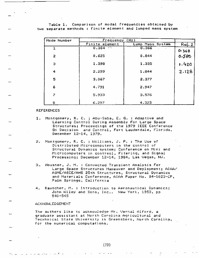
Table 1. Comparison of modal frequencies obtained by
two separate methods : finite element and lumped mass system
Mode Number
1
2
3
4
5
6
7
8
FrequencyFinite element
0.364 L,_
0.625
1.398
2.299
3. 067
4.791
5.933
6.297
(Hz)
Lump Mass System0.366
0.844
1.335
1.844
2.377
2.947
3.576
4.323
Z
O. _&8
o.ESo
i.4zo
Z.IZ
REFERENCES
i. Montgomery, R. C. ; Abu-Saba, E. G. : Adaptive and
Learning Control During Assembly For Large Space
Structures; Proceedings of the 1979 IEEE Conference
On Decision and Control, Fort Lauderdale, Florida,
December 12-14, 1979.
. Montgomery, R. C. ; 14illiams, J. P. : The Use of
Distributed Microcomputers in the control of
Structural Dynamics system; Conference on Mini andMicrocomputers in contreol, Fiterin9, and Signal
Processing; December 12-14, 1984, Las Vegas, NV.
3. Housner, J. M. : Convected Transient Analysis For
Large Space Structures Maneuver and Deployment; AIAA/
ASME/ASCE/AHS 25th Structures, Structural Dynamics
and Materials Conference, AIAA Paper No. 84-I023-CP,Palm Springs, California
. Rauscher, M. : Introduction to Aeronautical Dynamics;
John Niley and Sons, Inc.. New York, 1953, pp540-545
ACKNOWLEDGEMENT
The authers like to acknowledge Mr. Vernal Afford, a
9raduate assistant at North Carolina A9ricultural andTecxhnical State University in Greensboro, North Carolina,
for the numerical computations.
_ -- B -
(23)

t
1I j
I
!!I
;
I !' I
/
FIGURE %TRUC.T URF__.
(24)

S
F_GURE Z_. _RIO MQD-CL $1_NGLE. f"1A.S5
(25)

rO
v
-q.i.__
F
L_
ES)
V-
I

I I I I I I I I I I I I I I I• o
-11
r_
rTl
l
bnUf_
0
IllF"
©
0
qIP*
C_f ,/

APPENDIX B.
DYNAMIC ANALYSIS OF THE JOINT DOMINATED BEAM
(28)

DYNAMICANALYSISOF THE JOINTDOMINATEDBEAM
NAG-I-405
Project Director: Dr, EliasG, _bu-SabaArchitecturalEngineeringNorthCarolinaA&T StateUniversityGreensboro,NorthCarolina27411
NASAMonitor: Dr, RaymondMontgomeryNASALANGLEYRESEARCHCENTERHanpton,VA
ANNUALREPORT: Octoberi, 1985 - SeptenIDer30, 1986
DATE: October31, 1986
(29)

DYNAMIC ANALYSIS OF THE TRUSS BEAM
IN_I_0DUCTION:
The Truss-Beam as a cantilever has numerous applications
in the space construction field. When constructed of N-bays
with equal length and having chords of equal cross section,
the determination of the dynamic characteristics of such a
beam may be readily accomplished. The Maxwell receprocity
theorem along with a set of alogorithms help to generate the
flexibility matrix of the structure which in turn is used in
the dynamic equation of motion of the system.
DYNAMIC EQUATION
The general equation
structural
follows:
system can be
for the displacement of
written in the matrix
a linear
form as
{¥] = [A] [Q] (i)
where [Y}
{Q}
[A]
= Displacement Vector
= Force Vector
= Flexibility Matrix
In the absense of any external forces, a body in motion
will experience its own inertial foreces. These forces may be
neatly expressed by the following expression.
(I)
(30)

{Q] = - EM3{_] (2)
where[M3 = The mass matrix
[_] = Acceleration Vector
A joint dominated beam (truss-beam) is not homogeneous
because of the joints. The response of the joints is complex,
but for the sake of simplicity, the Truss Beam will be
considered as homogeneous and linear for the moment. Thus the
motion of the beam will be linear and periodic. Using the
periodicity of the motion, a relationship between the maximum
displacement and the acceleration is written as:
2 (3)£y] = - w [Y]
Where w is the frequency of the motion in radians per
second.
Substituting Equations (2) and (3) in Equation (i), one
obtains
Since the
[y] = w
bays in the
can be assumed to be equal.
mass matrix m can be expressed by:
[M] = m[I]
where EI] = Identity matrix
2EA] EM3 [Y] (4)
beam are equal, the nodal masses
If m is the mass of one bay, the
(5)
(2)
- (31)

Equation (4) can be simplified as
2{Y} = w m CA31' [Y]
1
or 0 = _A3 - --f-w m
[I_ £Y}
(6)
(7)
Furthermore, let the matrix
CA3 -_-_CI3 = CB3
Finally, the equation of motion
expressed by the equation
CB3 £Y] = 0
of the system
(8)
is
(9)
In a conservative system, the determinant of the matrix
CB3 must vanish in order to have a solution. The roots of the
polynomial generated from IBI = 0 will provide the eigen
characteristics of the system. Therefore the generation of
matrix CA3 is crucial to the dynamic analysis of the above
structure.
FLEXIBILITY OF THE TRUSS BEAM
Consider that the truss beam behaves as a
beam.
nodal
strain
See Figure i. For
displacements will
in the chords.
cantilever
a slender Truss-Beam the transverse
be mainly attributed to the axial
Thus the contribution of the web
elements can be neglected.
(32)
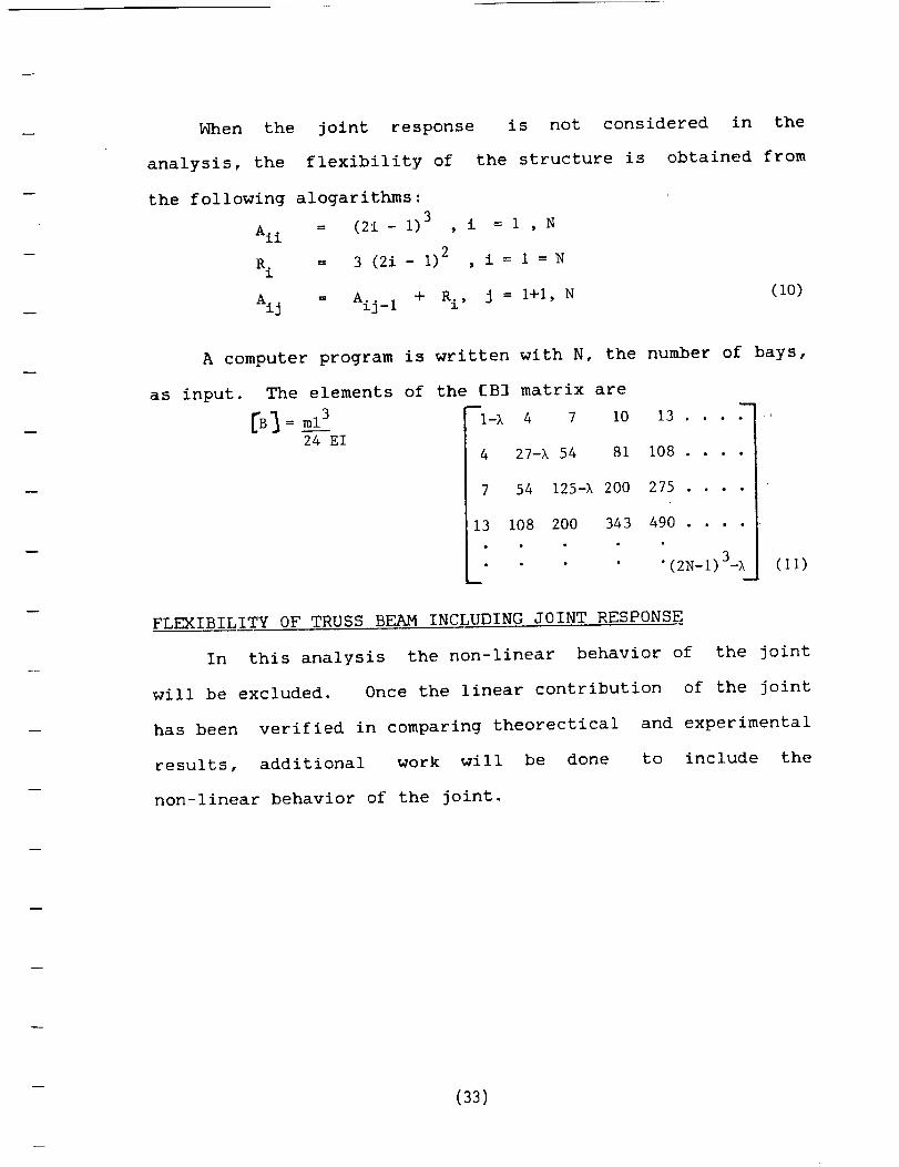
When the joint response is not considered in the
analysis, the flexibility of the structure is obtained from
the following alogarithms:3 i = i , N
Ai i = (2i- I) ,
R. = 3 (2i- 1)2 , i = 1 = N1
= Aij_ 1Ai j + Ri, J = I+i, N(10)
A computer program is written with N, the number of bays,
as input. The elements of the £B] matrix are
24 E14
7
13
4 7 I0
27-I 54 81
54 125-I 200
108 200 343
13 ....
108 ....
275 ....
490 ....
• (2N-I) 3-X (11)
FLEXIBILITY OF TRUSS BEAM INCLUDING JOINT RESPONSE
In this analysis the non-linear behavior of the joint
will be excluded. Once the linear contribution of the joint
has been verified in comparing theorectical
results, additional work will be done
non-linear behavior of the joint.
and experimental
to include the
(33)

The flexibility of the joint is obtained from the static
force acting on the joint as shown in Figure 2. Let this
flexibility be denoted by k. The new alogrithm will have the
following form:3 3 _"
A*.. = £ (2i - I) + si (2_-i)
13 24EI i = I, N
j = I,N(12)
where
S
E =
A_ =
224EI k(£)----r- h
Moment of inertia of the
Truss-Beam
Depth of the Truss-Beam
Modulus of elasticity of the
chords
Represent the flexibility matrix
which includes the joint
flexibility.
Then
B_
m
A _ Xll
! I L
t I %
m
A22 -X Aij*
31(14)
(34)

APPLICATION OF THE METHOD
Applying the method used in this report to
beam and neglecting <he join< contribution, the
a joint dominated
results are shown
in Table I & II for the ten moces of a truss beam of ten bays as
shown. Note the close a_reemen_ wic_ the results ootained for a
continuous cantilever oeam.
}_hen <he flexibility of t_e ioin< is ta!cen into consideraEion,
the frequency oI the system will drop as in_icace_ in 'fable [ fo_ a
variety of Z-valves. It is noticed tna< the [requencies do no<
vary significantly from one v&±ve of K tO anocher.
CONCLUSiO_-JS & F:E,2OMMENDAT!ONS
+h_ m=<nod used herein vie!ds _esuits very close _+o thoseolo_ained by t__e ciassicai me<hod for a uniformly +=is
ct-ibu<ed mass of cantilever beam
_[hen •ioint t!exibiii<Y is entered into <he solution t[_e
lo_:esc f_equency seems to go up by aDout nine oercen<.
- Hi,:her mode f_-equencies drop significantly
- Frequencies are no< sensitive to vat+iations in joint
flexiDili<y
- Free piay is not _art ot this method
- Viscous damping is i_nored
Ne _ecommenC as a continuation ot <•his re,ea_'c_ that
fO ] !OW:L,'qct p_'_P_,::b l_'e De t';3_-"it :-- _ T .... -
t'l'-=.rl ,•_er_['_tl,ir_m its+- _ + -- Mot.el ,._+: _oint zor _:.:iai _:rc_s and
J
flexibility Ene,-_,re_i,:al!Y
[he
- C35)
Check the dynamic characteristics of the joint dominatedbeam by entering the information about the joint asestablished above
Model the joint for linear and non-linear behavior andthen use that information in determining the dynamic
characteristics of the Joint-Dominated Beam
Compare the final results for the dynamic behaviorof the Joint Dominated Beam with results obtained by
the previous approaches
(36)

APPENDIXES
_ (37)

r_
ONEGA
c._o)tlllllllUh_llllll
1
2
3
4
5
6
7
8
9
10
I l°
!l!ii]l'"'"'""'"'""""-"i,,L,BEAM
$1 ilo=lol o.lgloll ill I..II0010It 0Oil 0I I100I _0101I, U_
3.52
22.03
61.70
120.90
199.86
298.56
416.99
555.17
713.08
890.73
TABLEI:
,,..ql,.,,.*,H,-,,-,,ll-,.,,=l
'r,,,.l',,,.[",,,r',,,,Il, _I _ "l jl......I......._L........,I......_I
I/TRUSS BEAM
NO JOINT ACTIONIInllllllNl IIII II411Wl lllllllll I IIIINI I IIIIIIII IIIII4111111MIIN hill II
3.53
22.21
62.50
123.03
203.03
- 304.33
420.65
542.99
647.B4
886.79
I,,,,l,,,""l...........,...........,........................ ..................I _,,. I', I ',, I"'.. I
lllUlllt..........,,l............,i...........,t........,.,,_..................TRUSS BEAM t JOINT ACTION
ool I uo ooN I oM Io II I _so aI I. It II o6ollolll iol ooololll onIII o1l ¢lOo I u II o I M Io II I 0II OOIll ¢lt OIll I OII I|Ul Ill I IIllllO snl so It i o ii o i N s, II o_I,I I __ I, l01 oU u, N O, ¢
lHlllllO_lO_lllll_Olllllll
1.0E-7INIINIINIIHIIIIINIINIIIII
3.85
9.90
15.34
21.71
24.60
30.50
39.99
57.93
103.77
392.35
k-values in/IbIIIIIIMIIIIIIIIIIIIINI MIINIIIIImlIIIIIUllll IIIIIlillllllllllI=lllll
1.3E-i
3.81
9.87
15.32
20.14
24.36
30.43
39.86
57.64
102.78
391.57
5.0E-E
3.92
9.95
15.45
20.23
24.68
30.63
40.24
58.54
106.12
412.96
1.0E-9HI|IIIIIINll IlOilll OOHll
3.99
10.01
15.54
20.30
24.76
30.78
40.56
59.32
lOlllilll.llillflll_llHIII
1.0E-10I o_m* No ,Iqg ,160 o_l _NIII, IIo I
3.99
10.01
15.54
20.30
24.78
30.78
40.55
59.34
109.70
:199.24
,---I
t..--I
r'_EL
,.,,-.,.
o0
, i t i I I I I I

g-ab g.. Comp_ r" _ZO_
me l 'ads
Mode ". wD _ we - -,_
12345 36 37 38 39 3
10 3
3 33 1.465 33 9.236 33 25.991 33 51.162
84.816126.555174.927225.802269.403368.770
31.443 38.754 3
23.410 33 43.2O0 33 66.680 33 92.510 33 119.600 33 147.100 33 3
3 -
5083
124173230
1.461
9 159
25 650 3
260 3070 3
i00 3
300 3
800 3
3
33 1.4543 8.827
23.60043.54067.25093.530
121.500150.500
a. Abu-Saba Methodb. exact method
c. Euler-Bernouilli beam, analytical
d. Timosheuko beam, FEH
References: C.T. Sun, B.J. Kim, J.L. Bogdunoff,AIAA, 1981#81-0624
APPENDIX:2
(39)

Tro ss C'an_-_16,-
S_c+lon o{: beam -_ru_
APPENDIX:3
(40)
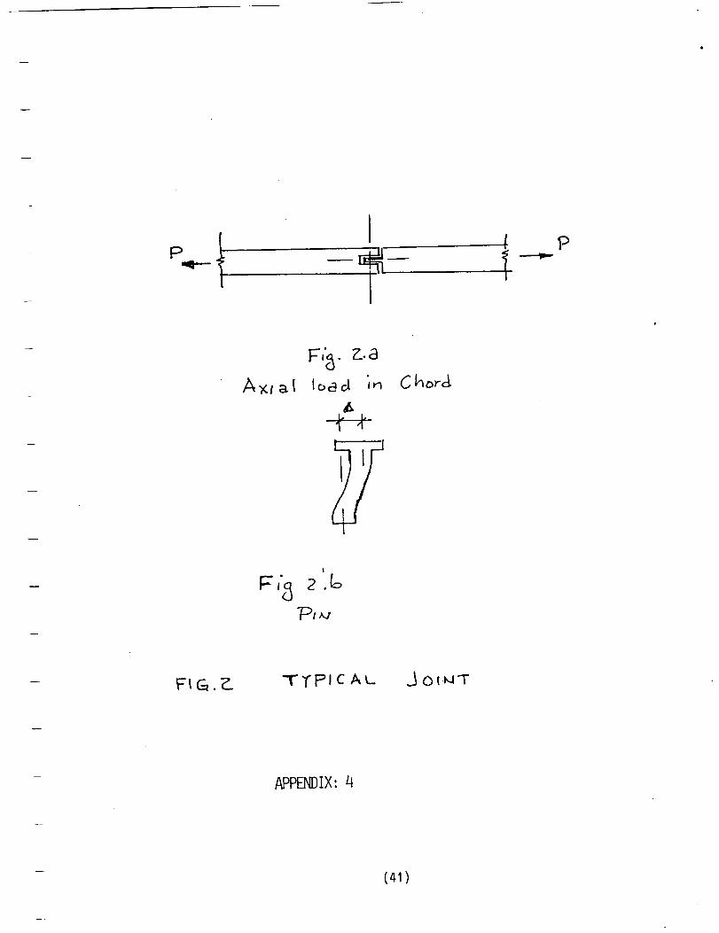
{ P
Axt_l
F','_ • Z..a
lo_cl In Chw-g
TTP'I C AL _ OlMT
APPENDIX:4
(41)

APPENDIX C.
WORK DONE BY MR. SHERWOOD HARRIS AS A GRADUATE RESEARCH
ASSISTANT ON THIS PROJECT.
(42)

GRANTNO: 4-43069
CHARACTERIZATIONOF FREE PLAY IN DEPLOYABLETRUSS-JOINTS
BY
Sherwood E. HarrisDepartment of Architectural Engineerinq
_]orth Carolina A & T State UniversityGreensboro, North Carolina 27411
September 1985
(43)

C,b
(
(
/_ _J_tO ._o_tt _ c..t_ _: •
- (44)

(
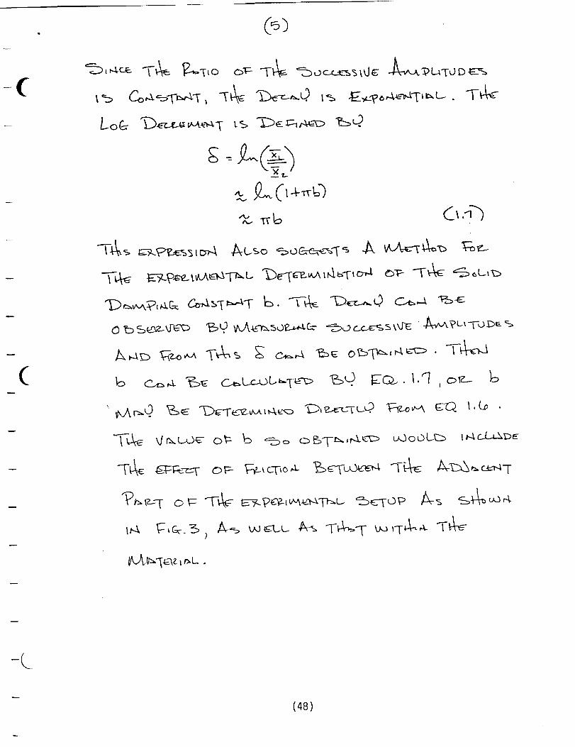
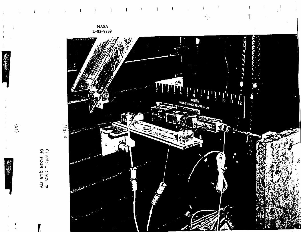
_s t_ '2..0 To _-.% toru
1
\.
(45)

(
(
I'
w \
(46)

(
0
i
(
'_1,%
-C_
_Q__. _._- • I._ _,_--_
J
2-_'½
(47)
(-
(
T_
-C
(48)

(
(
,_=>o "T'_'_ q- o_-
'Z.
A-,--,c) C_: C_%
.- 7..
L,L.) O0 L.-E3
•_-_ ,.o+_
1?___so u-r..4 _ 1A
(49)
"-o_-o..o.,,4c- W,,o_,o,4

I"l".Z'
?_-i I-f "_
5 n -
4-n -
.30 -
"' iZI
1 CI -
I-I •
(_,_w',7_t--,,,,iot,,-iv--.3 0 -
i
I
I I I t I I I I I
-- U, II 1 --I-I, I_-I17_]_ U, U I_1_:_-I_!, I_1I_-'14,- 17],I-I l-I 2
. /
.. '
_. _::.----
.l:=? "t'7._
o-1o 4-"
..-" _-
.... .7t i
,
I I I t ""1
I-I L-I, I_-I!-I2 I_-I,I_-I1_-I¢
X
i l l I i i II-I_,0 I-I G I-I,_I-1I-I .,q i-t._.:_,'-:I i i-i_, I-I1 z'_
i-nl
o
v
i i I I I I
I I _ I f I
NASA
L-85-9739
....a.
_ r
_, g7
t r,

HBCU _'...._'SA ....._
SOUTHERN UNIVERSITY AND A&M COLLEGE
tPRAIRIE VIEW A&M UNIVERSITY TENNESSEE STATE UNIVERSITY
tNORTH CAROLINA A&T STATE UNIVERSITY
l--
t
!-- ATLANTA UNIVERSITY FISK UN IVE RSITY
(52)

r
F
F-
_
|
i
!I
!
NORTH CAROLINA A&T STATE UNIVERSITY
PRINCIPLE INVESTIGATOR." Dr. Elias G. Abu-Saba
STUDENT." Mr. Sherwood Harris "
TECHNICAL MONITOR." Dr. Raymond C. Montgomery (LaRC)
Dynamics and Control of Orbiting Grid Structuresand the Synchronously Deployable Beam
ABSTRACT
Large flexible space structures are becoming an essential part of NASA's space effort.
Dynamic control of these structures presents a challenge to aerospace scientists. To better
understand the dynamic behavior of large space m-uc_es, the investigators provide mathematical
models for the grid. The grid as a whole behaves like a complex pendulum. The SPAR FEM
Computer Program is used to develop the elastic constants and the dynamic characteristics of the
model. A set of linear and nonlinear equations are obtained which def'me the dynamic behavior of
the system. Conclusions with regard to the dynamic response of the grid are employed in
developing the attitude modification scheme. ---
Free play in the joints ofdeployable structures is required to permit smooth deployment using
a low drive force deployer. To understand the effect of flee play on beam deflections a combined
analytical and experimental research is conducted to evaluate the significance of the various jointbehaviors that affect the overall stiffness of the beam. Linear and nonlinear aspects of the joints
are included.
This approach will be used to evaluate the dynamic behavior of the SOLAR ARRAY MAST
which was tested on board of the Shuttle Discovery in Spetember of 1984. Analytical results will
be compared with the data compiled from the test.
(53)
/

HBCU GRADUATE STUDENT WORKSHOP
NATIONAL AERONAUTICS AND SPACE ADMINISTRATION
LANGLEY RESEARCH CENTER
HAMPTON, VA
p
November 8, 1985
Sponsored By:Chief Scientist, Jerry C. South, Jr.,
Office of Director
- (54)

SHERWOOD E. HARRIS
NORTH CAROLINA A&T STATE UNIVERSITY
RESEARCH TOPIC: Damping characteristics of f_ee play in
Deployable Truss Joints
ABSTRACT: The "Next Generation" spacecraft are being conceived
that are highly flexible and of large size. The compact sLoraqe
requirements for launch require subassemblies of large flexible
spacecraft to be joined together on orbit to build-up the
structure to the required dimensions. Of the structural elements
which perform this function, joints are seen to be the major
source of the non-linear response of the system.
/
One potential problem associated with joint dominated structures
is free play in the joints. Some free play in deployable
structures may be required to permit smooth deployment using a
low drive force deployer. The amount of free play is also
associated with machine accuracy requirements. To unde_starld the
effect of free play on the dynamic behavior of the structure an
experiment was performed on a deployable truss joint w_th
hardened steel pivot pins.
The results obtained indicate free play in the range between
zero and 50 ibs. This is directly linked to the non-linear
behavior of the system. In addition, energy absorption and
dissipation by the material augment the non-linearity of the
structure. The joint hysteresis is caused by friction of the
pins in the connections as they slip or slide during deformation.
Based on the experimental data, a mathematical expression is
established to predict the solid damping constant. Similarly,
another mathematical expression is obtained to define the
decaying motion of the system.
RESUME :
FACULTY ADVISOR:
LARC ADVISOR:
B.S., Architectural Engineering, North
Carolina A&T State University, 1980;
Work experience: Structural Engineer,
Niagara Mohawk Power Corporation, Syracuse,
New York, currently enrolled in M.S. program,
Engineering, North Carolina A&T State
University.
Dr. Elias G. Abu-Saba
Dr. Raymond C. Montgomery
(55)

APPENDIX D
PRESENTATION BY MR. HEBRh-T_ L. DIXON
(56)

!
HBCU GRADUATE AND UNDERGRADUATE STUDENT
SCIENCE AND ENGINEERING WORKSHOP
NATIONAL AERONAUTICS AND SPACE ADMINISTRATION
LANGLEY RESEARCH CENTER
HAMPTON, VA.
November 7, 1986
r
Sponsored by:Chief Scientist, Jerry C. South, Jr.
Office of Director
(57)

HEBREW DIXON
NORTH CAROLINA A&T STATE UNIVERSITY
!:
RESEARCH TOPIC: .Dynamic Analysis of the Joint Dominated Beam
ABSTRACT: A method is presented herein to determine the vibration
mode of the Joint Dominated Beam. An example of a cantilever beam is
selected for this purpose. The truss type beam is analysed as a
homogeneous section with the equivalent moment of inertia derived fromthe contribution of the chords only. Such an assumption is justified
for slender beams for which the deflections due to web strains is
neglegible.
Based on the above assumptions, a lumped mass system is selected as a
model. The flexibility of the system is derived from the deflection
equation of the cantilever beam. Maxwell's law of reciprocity isutilized in order to minimize the computational procedure. A set of
alogari thmi c statements is obtai ned.
First, the joints in the beam are considered to be an integral part of
the beam. The flexibi lity matrix is obtained and the equation of motion
written. Given N as the number of bays, a computer program has been
written to provide the natural frequency constant of the beam. The ....valves of the frequencies for the first ten modes are compared with those
obtained by the classical method. The results from the method used herein
are compared with the results of a number of examples performed by other
methods and authors.
Second, the joint flexibility is denoted by k, and a new set of alogarithmic
statements are obtained which involve the behavior of the joints. A
modified flexibility matrix is obtained and another set of natural fre-
quencies is obtained. Various values of k are used and the frequency out-
put is recorded. Some conclusions are made based on these results.
RESUME: B.S., Architectural Engineering, North CarolinaA&T State University; currently for M.S. Degree
in Architecture
FACULTY ADVISOR: Dr. Elias G. Abu-Saba
LaRC ADVISOR: Dr. Raymond Montgomery
(58)

APPENDIX E.
PRESENTATIONS BY DR. ELIAS G. ABU_SABA:
TO NASA STAFF AT LANGLEY RESEARCH CENTER
TO ASCE: 88 SPACE STRUCTURES
(59)

N/ SALangley Research Center
BRIEFING
TRUSS BEAM: DYNAMIC ANALYSIS
Dr. Elias G. Abu-Saba
North Carolina A&T State University
Greensboro, NC
BI268A, RII41Tuesday, 6/24/86
10:00 a.m.
June 1_, 1986i
O&¥E .
Abstract
The truss-beam used as a cantilever will be analyzed for dynamic
behavior. First, the Joints are treated as frlctlonless and with no
damping or sllpage. The truss-beam is considered to be linear and with
small dlsplacements. The flexlbillty matrix is thus generated from one
basic equation. Second, the Joints are included in the analysls. Energy
loss of the Joints is computed experlmentally or at first assumed. The net
strain energy of the system is obtained and node dlsplacements are
computed. A modified flexibility matrix is arrived at and used to calcu-
late the elgenvalue characteristics. Models will be constructed and tested
for dynamic behavior, and the results will be compared with the theoretical
values. Concluslons will be drawn to upgrade the theory Iteratlvely until
experlmental and theoretlcal results converge. Jeffrey P. Willlams, X4591,
is coordinating this meeting.
Distribution:
479/GCD
244/SDD
430/SED
230/SDB
]6I/SCB
356/COFS Project Office
479/Anderson, W. W.
479/Sllwa, S. M.
]6t/Taylor, L. W., Jr.
161/Keckler, C. R.
364/Goslee, J. W.
364/Garrett, L. B.
244/Card, M. F.
230/Hanks, B. R.
356/Bohon, H. L.
356/Allen, J. L., Jr.
356/Pyle, J. S.
356/Fedors, J. C.
430/Muraca, R. J.
429/Watson, W. I.
433/Gowdey, J. C.
(60)