Embed Size (px)
Citation preview

Detailed D
esign Study of Water Supply
and Sewerage System for Astana City
Final Report
2-52
Figure 2.3.8-3 Drawing of Typical Pump Station (Large Size) – 3/3

Detailed Design Study of Water Supply and Sewerage System for Astana City
Final Report
2-53
4) Sewers and Manholes
ⅰⅰⅰⅰ) Sewers
Inventory of sewers was investigated. Construction of sewers started in 1951. The
inventory of a total sewer length of 226.6km provides information on location, diameter,
length, material type, construction year and manhole numbers in each pipeline.
Figure 2.3.9 shows the sewage collection network. Specific feature of the network is as
shown below:
- A pressure line basically consists of double lines.
- Pressure lines are made of steel pipe, 14% of total length
- Cast-iron pipe is broadly used, 40% of total length.
- Concrete pipe is relatively low in composition percentage.
- Asbestos-cement has about 20 %, most of them are utilized for small diameter pipeline
below 300mm.
- Use of asbestos-cement pipe is not restricted at present, which may cause the lung disease
asbestosis.
Table 2.3.10 Composition of Different Pipe Materials
Pipe Material Length (m) Percentage Remarks Asbestos-cement 45,461.51 20.1 Cast-iron 85,380.96 37.7 Ceramics 32,574.45 14.4 Reinforced concrete 27,929.70 12.3 Mainly gravity collector Polyethylene 2,240.00 1.0 Steel 32,264.80 14.2 Mainly pressure collector Other 727.00 0.3 TOTAL 226,578.42 100.0
As for the installation depth of sewers, some pressure lines are installed above the ground.
ii) Manholes
A total of 5,279 manholes were found in the above-mentioned inventory. From this number,
average distance between two manholes is calculated approximately 43m. Through the field
investigation, numbers of 5,213 manholes were confirmed as described in the next section.

Detailed Design Study of Water Supply and Sewerage System for Astana City
Final Report
2-54


Detailed Design Study of Water Supply and Sewerage System for Astana City
Final Report
2-57
2.3.3 Field Confirmation
(1) Results of Investigation on Manhole Cover
A Total of 5,213 manhole covers were confirmed through the field investigation against the
numbers of 5,279 in the inventory list. Typical example of manhole covers through
investigation are shown in Appendix.
In general, status of manhole is not in good condition. The covers on the road are badly worn,
remaining shallow groove of cast pattern on the surface. The covers are also rusted seriously
when they are located in the pavement even if they have enough groove depth. Only 2% of
manholes of total number were judged as “good” condition. Early replacement of all the
manhole covers is recommended for the safety.
(2) Result of Sewage and Sludge Quality Examination
Water and sludge quality examinations were conducted during early October in 2002 and during
in March 2003 to evaluate existing treatment process and clarify environmental problems.
1) Evaluation of water and sludge quality
Water and sludge quality data are included in Appendix. The following are summary of the
evaluation.
i) Sewage treatment
• Inflow sewage quality results are almost the same as those examined by STP laboratory in the past.
• Concentrations of organic substances of the sewage is considered to be standard level of domestic sewage
• Sewage and sludge treatment efficiency is satisfactory.
• Effluent water quality meets design water quality standard.
ii) Sludge treatment
• Raw sludge concentration is very high (5%) because of the operation method of primary sedimentation tank.
• Excess sludge is about 2000mg/l MLSS with the good settlement characteristics.
iii) Taldy kol reservoir
• Water quality is similar to effluent from the STP other than items of nitrogen and phosphorus.
iv) Water in the natural channel at Marshland extended from the STP
• TN and TP at the marshland are remarkably lower than those of Taldy-kol reservoir.
• COD, BOD and SS are almost on the same or slightly higher level comparing with the reservoir water quality.

CHAPTER 3 CONFIRMATION OF THE OUTLINE OF JBIC ASSISTED PROJECT

Detailed Design Study of Water Supply and Sewerage System for Astana City Final Report
3-1
CHAPTER 3 CONFIRMATION OF THE OUTLINE OF JBIC ASSISTED PROJECT
3.1 General
Fieldwork was conducted to update the information on existing water supply and sewerage
systems as discussed in Chapter 2. In addition, discussions on the details of the proposed
facilities were made with concerned parties to come up with quantities/specifications by
facility.
Because of some development by the ASA since the time of F/S completion and other field
findings on the deteriorating conditions of facilities, final confirmation on the scope of work
was carried out during the basic design stage.
Based on the results of the basic design (B/D), some modifications of the scope of the work
for JBIC assisted project was made between JBIC and Kazakhstan side on February 17, 2003.
The scope of the work agreed in the Minutes on Discussion (M/D) between JBIC and the
Government of Kazakhstan signed in February 2002, is in principle maintained except for the
following countermeasures:
(1) Omitted Item based on B/D
• Construction of one unit of water distribution pump station at WTP is canceled based
on B/D study. Existing water distribution pump station will be used for the water
supply to the new government area.
• Construction of one unit of sludge digestion tank at STP is canceled based on B/D
study.
(2) The item that Kazakhstan side will undertake
• Rehabilitation of raw water transmission pipe (No II line)
(3) The item that scope of work is reduced
• Operation and Maintenance Equipment: Some construction machines are reduced
under the idea that major construction work is contract out.
(4) Some additions within the frame work of M/D in the E/N
• Rehabilitation of existing water distribution pump station instead of the construction of
a new pump station at WTP
• The replacement of about 100 km distribution pipes is kept, although pipe diameters
increased considerably comparing with previous assumptions.
Table 3.1.1 presents the scope of work for preparation of Detailed Design. Figure 3.1.1

Detailed Design Study of Water Supply and Sewerage System for Astana City Final Report
3-2
shows location of distribution pipes to be replaced. Refer to Table 3.4.1 for the list of O&M
equipment.
Table 3.1.1 Scope of Work for Preparation of Detailed Design
Compone
nt Major Facility Component
Facilities/Equipment Descriptions
Intake Tower Construction; Capacity 210,000 m3/d x 1 unit (including Mechanical Room, Electrical Room & Staff Room)
Access Road Construction; Width 6 m x Length about 300m
Mechanical Equipment Procure & Install; Pump: 36.5 m3/min x 6 units(including 2stand-by)
Water Intake Facility (210,000m3/d)
Power receiving and distribution facility Procurement and installation
Raw Water Transmission Facilities Transmission Pipeline Not Applicable
Distribution Chamber 1 unit with a capacity of 210,000m3/d including production loss
Receiving Well 2 wells with a total capacity of 105,000m3/d including production loss
Chemical Mixing Tank 2 units with a total capacity of 105,000m3/d Flocculation Basin 6 trains with a total capacity of 105,000m3/d Sedimentation Basin 6 units with a total capacity of 105,000m3/d Rapid Sand Filter 12 units with a total capacity of 105,000m3/d
Washing Drain Basin 2 units with each capacity of 1,280m3; 2 units each of return water and sludge drain pump
Sludge Thickener 2 units with each capacity of 890m3 with 2 units of sludge drain pump
Sludge Drying Bed 6 beds with each dry area of 900m2 Cake Yard 600m2 Discharge Pool 2 units with each capacity of 1,000m3
Chemical Feeding Facility Alum, Polymer, powdered Activated Carbon for 105,000m3/d;
Chlorine Feeding Facility Chlorine Injection Facility, Chlorination Room
Administration Building Served both for proposed and existing water treatment systems (2,430m2 – 3 stories)
Measuring/Examination Equipment Laboratory equipment
Power receive and distribution facility Outdoor type transformer 11,35 / 6 kV Duplex
In-plant Piping System 75mm – 1600 mm x length 5,350 m
Water Treatment Facility (100,000m3/d)
Monitoring & Control System SCADA; Central monitoring system Distribution Pump Station M& E equipment partial rehabilitation Distribution Pipe Construction: Pipe diameter 1000mm x length 5.6 km Water Distribution
Facility Distribution Pipe Replacement: Pipe diameter 100 to 1000 mm x length 100
km
Wat
er S
uppl
y
Service Facility Water Meter Procure & install: Domestic Water Meter 152,000 units and Bulk Meter 1,900units
Inlet Screen Replacement of Existing screen facilities
Lift up Pump Replacement of Existing Pump of 0.9 m3/sec x 2units and 0.45m3/secx2units; Rehabilitation of inlet BLDG
Inlet Pipe Replacement of pipes; receiving chamber-pump pit and pump pit-Grit Chamber
Grit Chamber Construction of 2 units made of RC
Primary Sedimentation Tank
Rehabilitation of mech. equip. for existing 6 tanks (dia 28m)and raw sludge pump facilities; Construction of 2 tanks (same capacity as existing one) including raw sludge pump facilities
Sew
erag
e
Sew
age
Trea
tmen
t Pla
nt
Sewage Treatment Facility (136,000m3/d)
Blower Facility Replacement of 20,000 Nm3/hr x 5 units, Rehabilitation of Blower Building

Detailed Design Study of Water Supply and Sewerage System for Astana City Final Report
3-3
Aeration Tank Rehabilitation of Tanks
Final Sedimentation Tank
Rehabilitation of mechanical equipment for Existing 10 tanks with diameter 28m, Construction of 2 tanks with the same capacity of existing one
Return Sludge Pump Replacement of Pump of 950 m3/hr x 5units, Construction ofpump room
Rehabilitation of Discharge Pump
Replacement of existing pump of 0.9m3/secx2units; 0.45m3/secx2units and 80m3/hrx2units
Sewage Treatment
Facility
(136,000m3/d)
In-plant Pipe/Channel Dia 200mm – 2000 mm x length 3,000 m
Rehabilitation of Gravity Thickener
Rehabilitation of Mechanical Equipment, Replacement of Pump of 80 m3/hr×4 units, Replacement of Tank Cover (Existing tank; diameter 20m x 2 tanks)
Installation of Mechanical Thickener for Excess Sludge
Installation of Mechanical Thickener of 75 m3/hr x 3 units; Construction of Polymer Feeder Facility, Sludge Holding Tank, Thickened Sludge Holding Tank and Thickener Room
Rehabilitation of Sludge Digester
Installation of Mixer and Replacement of heating equipment in the existing 2 tanks (Volume 2,500m3)
Rehabilitation of Digester Equipment
Replacement of Boiler (4.5t/hr x 2 units); Rehabilitation of Gasholder (2 units)
Sludge Treatment Facility
Sludge Dewatering Unit
Installation of Dewatering Unit, Polymer Feeder, Sludge Feed Pump and Sludge Cake Convey Equipment; Construction of Dewatering Building (staff room and controlroom)
Measuring/Examination Equipment Laboratory equipment
Electric Facility Lump Sum In-plant Landscaping Lump Sum
Sew
age
Trea
tmen
t Pla
nt
Common Facility
Monitoring & Control System Lump Sum
Intermediate Pump Station Rehabilitation of 17 Pump Stations Replacement of Mechanical/Electrical Equipments for 17 Pump Stations
Sewers Replacement of Pipes of Diameter 100mm to 800mm, Total Length 21 km
Sew
erag
e
Sewers
Rehabilitation of Manhole Cover Replacement of 5,300 Manhole Covers
Common Procurement of Operation and Maintenance Equipment
Power Shovels, Excavators, Trucks, Truck Cranes, Machine Tools, Patrol Cars, Generators, Road Pavement Heavy Machines, etc.

Detailed D
esign Study of Water Supply
and Sewerage System for Astana City
Final Report
3-4
400
300
300
900
500
400
700
300 400
300
300
200 400
300
300
300
400 400
300
300
300
400
200 300 400
400
500
400
400
300 500
400 200
1000
300
200
200
300
400
300 400 400
600
400
300
400
250 250
600
200 300 200
500
300
700 300
300
300
400
300
300 200
1000 700
600 400
200 200 150
600
600
600
200 200
200
100 200
100 250
600
400
S=1/70000 Масштаб 1:70000
Figure .3.1.1 Location of Pipes to be Replaced
Чертеж 3.1.1 Расположение труб, которые будут заменены
800
500
800 400
WTP НФС

Detailed Design Study of Water Supply and Sewerage System for Astana City Final Report
3-5
3.2 Water Supply Facilities
Table 3.2.1 summarizes major facilities to be either constructed or rehabilitated/replaced.
Table 3.2.1 Concerned Water Supply Facilities for the Project
Major Facility Description Remarks 1. Water Intake
Facility ・ Construction of one unit of water intake
facility at Vyacheslavsky reservoir (Capacity 210,000m3/d)
・ Access road construction to meet the regulation for construction of facilities in public water body (sanitary buffer zone)
・ Intake pump facilities to meet the manner of use of 2 parallel raw water transmission pipelines
・ Power receiving and distribution equipment
・ To ensure 200,000m3/d of the capacity of water treatment plant, 5% water loss is additionally counted.
・ Location of the facility was re-studied (out of 100m radius from existing facility).
・ Depending on reliability of the existing pipelines, required pump capacities are different (oldest pipeline is not used).
2. Raw Water Transmission Facility
・ Replacement of pipeline with a total length of 15 km between the WTP and Vyacheslavsky reservoir
・ Four replacement sections
・ Four priority sections were identified based on the leakage records. This portion shall be conducted by Kazakhstan side.
3. Water Treatment Plant
Construction of water treatment facilities within the premises of existing WTP ・ Water Treatment Facility - Receiving Well,
Rapid Chemical Mixing Tank, Flocculation Basin, Sedimentation Basin, Rapid Sand Filter and Chlorination Tank
・ Wastewater Treatment Facility – Washing water drainage tank, Sludge thickener, Sludge drying bed and Discharge pool
・ Administration Building ・ Measuring/Examination Equipment ・ Power Receiving & Distribution Equipment ・ In-plant Piping System
・ Water Treatment Facility:
4.Water Distribution Facility
(1) Distribution Pump Facility: Replacement of distribution pump facilities for water supply to new governmental area
(2) Distribution Pipeline: 1) Construction of main distribution
pipeline with a length of 5.6 km 2) Replacement of existing distribution
pipes with a total length of 100 km
・ Distribution pump facilities shall include pump facilities and electrical facilities.
・ The length of main distribution line was reduced. Further requirements will be managed by Kazakhstan funds.
・ Reflecting current improvement achieved by ASA in right bank area of the Ishim River, contents of pipes changed from dia 100mm–500mm to dia 100mm–1000mm.
5.Service Facility
Procurement and installation of water meter ・ Domestic individual meter: 152,000 units ・ Bulk water meter: 1,900
6.Monitoring and Control System
・ Water Intake Facility ・ Water Treatment Plant ・ Water Distribution Pump Facility

Detailed Design Study of Water Supply and Sewerage System for Astana City Final Report
3-6
3.3 Sewerage Facilities
Table 3.3.1 summarizes major facilities to be either constructed or rehabilitated/replaced.
Table 3.3.1 Concerned Sewerage Facilities for the Project
Major Facility Description Remarks
1.Sewage Treatment Plant
Rehabilitation and expansion of the existing sewage treatment plant to ensure treatment capacity of 136,000m3/d
-Sewage Treatment Facility – Inlet Screen, Lift-up pump, Inlet pipe, Grit Chamber, Primary Sedimentation Tank with raw sludge pump facilities, Aeration Tank, Blower Facilities, Final Sedimentation Tank with return sludge facilities, Discharge Pump Facilities, In-plant pipe/channel
-Sludge Treatment Facility – Sludge Thickener, Mechanical type Sludge Thickener, Sludge Digestion Tank and its supplementary equipment, and Sludge dewatering equipment and its BLDG with a staff/control room
-Measuring/examination Equipment
- Electrical Facility
- In-plant Landscaping
All units of sludge clarifier both for Primary and Final Sedimentation Tank are deteriorated requiring replacement. But, only 2 units of each tank are considered as agreed in M/D.
Inlet facilities are deteriorated requiring replacement, but only original countermeasures are adopted
2.Sewage Collection System
(1)Intermediate Pump Station: Rehabilitation of existing 17 pump stations
(2) Sewers: Replacement of existing sewers: 21 km
(3)Manhole covers: Replacement at 5,300 points
Replacement of intermediate pump facilities include screen, flow meter and pump unit.
3.Monitoring and Control System
Sewage Treatment Plant
Intermediate Pump Station
3.4 Common Requirements for O&M to Water Supply and Sewerage Project
Among equipment/machine required for operation and maintenance of the facilities are heavy
machine for civil work, various kind of vehicles and others.
Table 3.4.1 List of O&M Equipment to be Procured
No. Item Type Specification No. 1 Bucket Loader TO-40 Big Bucket - 2m3 1
2 Excavator UDS-114A, Truck Base Bucket – 0.35-0.65m3 2
3 Excavator Made in Japan or Germany 3
Frozen Ground Excavator Blade Length 2.8m 2 Ditto Tractor Base MTZ Blade Length 1.5m 1 4 Ditto Tractor T-150 Base Blade Length 2.8m
5 Steam Generator Base of off-road truck 2

Detailed Design Study of Water Supply and Sewerage System for Astana City Final Report
3-7
6 Dump-truck Loading 10t 5 7 Wagon Truck 5
Truck Crane Boom Length 25m Load 16t 1 8 Ditto Load 10t 2 Trailer Loading 40t 1 9 Ditto Loading 20t 1 Channel Washing Machine KO-514 Base Kamaz 2 Ditto KO-514 Base Zil 2 10 Ditto KO-560 Base Kamaz 2
11 Sewer Washing Machine DTK-260 Base Zil53016 1 12 Vacuum Vehicle KO-503V 10 13 Flusher KO-829-1 Base Zil-5301 2 14 Off-road Vehicle 5 15 Pipe Layer TP12.04 Load – 6-12t 2 16 Compressor K-2 10kg/cm3 2 17 Welding Transformer TDM-401 5
Generator Up to 2.2kW 2 Ditto Up to 4.5kW 2 Ditto Up to 3kW 1 18
Ditto Up to 75kW 1 19 Sub-merged Pump 20-100m3/h 10
Pump + generator 200m3/hr 1 20 Ditto 500m3/hr 1 21 Trace Detecting Machine 2 22 Leakage Detecting Machine 2 23 Potable Ultrasonic Water Meter 8 24 Flow Meter gravity and canals D300-800 2 25 Mobile Laboratory ETL-35 Truck Base 1 26 Water Meter Testing Factory D15-50mm 1 27 Passenger Bus 2 28 Truck Crane Boom length up to 22m 1 29 Maintenance and Repair Center 1
30 Laboratory for Pipe Teleinspection 1
31 Horizontal Boring Machine UGB-3A D=0-600mm 1 32 Trenchless Pipe Layer D=50-600mm 1
33 Groundwater Level Reduction Unit Up to 15 m 2
34 Polyethylene Pipe Welder D=50-400mm 2 35 Operation and Maintenance Information Equipment 1
Equipment for the Workshop for Maintenance and Repair of the Pump Equipment and Valves 36 Vertical Turning Lathe M-1532 1 37 Horizontal-milling Lathe M-6T82G 1 38 Vertical-milling Lathe M-6T13 1 39 Hydraulic Press M-P6330 P-200-599bar 1 40 Vertical-drilling Lathe M-2S132 3 41 Tool-grinding Desk Machine M-3L631 5 42 Screw-cutting Lathe M-16VT20P.02 4 43 Screw-cutting Lathe M-1M63N 3 44 Slotting Machine M-7402 2 45 Jig saw M-8725 2 46 Guillotine Crank Shears M-NG-13 2

CHAPTER 4 GENERAL APPROACH AND CONDITIONS AND ASSUMPTIONS FOR FACILITY DESIGN

Detailed Design Study of Water Supply and Sewerage System for Astana City Final Report
4-1
CHAPTER 4 GENERAL APPROACH AND CONDITIONS AND ASSUMPTIONS FOR FACILITY DESIGN
4.1 General Approach for Facility Design
The scope of the project with JBIC loan amount was agreed between JBIC and Kazakhstan
side. Therefore, planning fundamentals and conditions for the facilities that are the outputs
of F/S were given conditions for detailed design study. Accordingly, the study focused on
the detailed methodologies and specifications of the facilities to come up with the detailed
design.
4.2 Approach to Water Supply Component Design
Rehabilitation and construction of concerned facilities should be planned/designed to ensure
effective combination of component facilities and comprehensive arrangements with existing
facilities.
The following were common consideration for design of water supply facilities:
1) Determination of appropriate/economical facility capacity, though SNiP standard should
be referred to.
2) Considering cold climate, easy O&M should be sought such as a provision of roof/cover
over the facilities.
3) Priority should be rather given to the quality, however, selection of materials and
equipment/machine for easy procurement of spare parts was considered.
4) Construction plan should be prepared in full consideration that rehabilitation work had to
be done without disturbing the operation of the existing facilities.
5) Careful consideration should be given on the cold climate in civil work (no use of frozen
soil, etc.)
Approach by major facility is described below:
(1) Water Intake Facility
The intake tower, which will be constructed in the reservoir, would be designed to take
water at different water levels to ensure stable water intake through the year in
quantity-wise and quality-wise. The tower is located 100m far from existing facilities in
accordance with the SNiP standard.
High turbid water may be arisen during the construction of the new facilities in the
reservoir. The measures to minimize the influence to the existing intake works shall be

Detailed Design Study of Water Supply and Sewerage System for Astana City Final Report
4-2
provided. The location of the new facility would be determined base on the results of
topographic survey in the reservoir.
The channel to introduce raw water to the new intake tower would be arranged with the
invert level of + 387 m, which is the same bottom level of the existing intake tower (see
Figure 4.2.1). The depth of foundation of the intake tower should be determined with
sufficient safety in relation to supporting soil strata conditions. The soil bearing force of
the planned strata is sufficient enough for supporting the facility based on the existing
data and the results of the soil boring test.
Figure 4.2.1 Water Intake Tower
(2) Water Treatment Plant
A new water treatment plant with a capacity of 100,000 m3/d should be designed. The
treatment process adopted in the existing plant (chemical coagulation, sedimentation and
rapid sand filtration) is also adopted for the new plant. The existing distribution
reservoirs will be utilized, and a part of existing distribution pump facilities will be
replaced to meet the capacity of the new treatment plant (including the supply to new
built-up area in the left bank area of Ishim River).
As the measures against cold climate, roof/cover and heating systems to the facilities,
where daily O&M work is necessary, shall be provided. As common measures required
for cold climate, the following were considered; additional depth of the foundation
bottom of the facilities than warm climate area, pile foundation and soil cover.
(3) Construction of distribution pipeline and replacement of existing distribution pipeline
For new distribution pipeline (5.6 km with dia. 1,000mm) and for replacement of about
100 km existing pipelines, construction sections should be identified by Astanagenplan
and ASA through the D/D study. The pipeline routes should be selected along the roads
for easy maintenance of the pipeline system.
Hydraulic calculation of distribution network should be made for the years of 2010, 2020
Foundation Bottom:380.7m Excavation Part
Reservoir Bottom HWL:403m
Lowest Intake Level:387m
Supporting Strata:382.5m
Intake Tower

Detailed Design Study of Water Supply and Sewerage System for Astana City Final Report
4-3
and 2030 under the established conditions in M/P.
(4) Procurement and installation of water meter
The target number of water meters to be installed should be 153,900 units (152,000 for
households and 1,900 for apartment houses). The manner of installation of the meter in
terms of location, plumbing, meter reading should be categorized.
Type and specifications of the meter should be determined based on the present manner of
meter installation by ASA.
4.3 Approach to Sewerage Component Design
Rehabilitation and construction of concerned facilities was planned/designed to ensure
effective combination of component facilities and comprehensive arrangements with existing
facilities. The following are common consideration for design of sewerage facilities:
1) Determination of appropriate/economical facility capacity, though SNiP standard was
referred to
2) Considering cold climate, easy O&M was sought such as a provision of roof/cover over the
facilities.
3) Priority was given to the quality. In selection of materials and equipment/machine,
however, easiness of procurement of spare parts was also considered.
4) Construction plan was prepared in full consideration that rehabilitation work had to be
done without disturbing the operation of the existing facilities.
5) Careful consideration on the cold climate in civil work (no use of frozen soil, etc.)
(1) Sewage treatment process
The work was either rehabilitation or expansion by respective unit facilities. The
following are required considerations by major facility.
1) Rehabilitation of Inlet Pump Facility and related equipment
Stage construction shall be employed in consideration with the no suspension of
sewage treatment operation.
2) Construction of Grit chamber
Alternative facilities were studied for easy operation and maintenance including
compact type such as vortex type, aerated type and horizontal flow type.
3) Rehabilitation and Construction of Primary and Final Sedimentation Tank

Detailed Design Study of Water Supply and Sewerage System for Astana City Final Report
4-4
With regard to the construction of sedimentation tank, the need of the facilities was
studied referring to operation condition of the existing facilities, existing data on
O&M including water quality examination and design criteria to suite for local
conditions.
4) Rehabilitation and Construction of Return Sludge Pump
Findings from field investigation were the basis for design of
rehabilitation/construction of the facilities.
5) Rehabilitation and Replacement of Blower Facilities
An appropriate type of blower was selected in consideration of effectiveness and easy
O&M under the requirement of a large capacity.
As a common consideration to finalize the scope of rehabilitation/construction, current
rehabilitation performed by the ASA was considered and equipment to be procured was
determined referring to existing ones for easy O&M by ASA staff.
(2) Sludge Treatment Process
The projection of a total volume of generated sludge that was included in the return water
from sludge thickener and sludge dewatering machine should be done. Sludge moisture
content ratio and dewatering efficiency were analyzed through field examination to come
up with accurate sludge volume.
Sludge treatment facilities comprise sophisticated devices/equipment, thus O&M is rather
difficult than sewage treatment facilities. Accordingly, selection of sludge treatment
system and type of machine should be made based on a study on O&M technology
available and acceptable cost level in Kazakhstan. Alternative study on some sludge
treatment systems was made to select the system to meet the local conditions.
In application of sludge dewatering facilities as a first trial in the country, durability, easy
repair work and easy procurement of chemicals and consumables required were studied.
(3) Rehabilitation of Existing Intermediate Pump Station
The intermediate pump station is illustrated in Figure 4.3.1. The detail scope for
civil/architectural work and pump facilities (mechanical and electrical work) was
recommended based on investigations at the planned pump stations.

Detailed Design Study of Water Supply and Sewerage System for Astana City Final Report
4-5
Figure 4.3.1 Intermediate Pump Station
4.4 Approach to Architectural Design
4.4.1 Architectural Design Criteria
Architectural design was implemented in accordance with SNiP code and the International
Design Standard.
Amenity room area and Utilities area are calculated in accordance with SNiP 2.09.04-87
“Administrative and Amenity Buildings”.
4.4.2 Design Policies
Design of architectural work was performed under the following policies:
・ Functional design to provide efficient management and operation
・ Locality (the climate and the customs) should be taken into consideration.
・ Local construction methods and local materials should be used as much extent as
possible considering the construction term and cost.
・ Design should be made to ease the maintenance with a minimum cost.
・ Facilities should be not only functional but also pleasant as working environment
4.4.3 Design Elements
The basic design elements consist of four (4) physical characters as follows and these were
applied to the plan and design of major buildings:
(1) Rigid Fine Bricks
Inlet
Pump Room
Pump Pit Plumbing
Outlet

Detailed Design Study of Water Supply and Sewerage System for Astana City Final Report
4-6
Rigid fine brick of walls is effective not only in resisting cold weather but also in keeping the
fineness as finishing material.
(2) Curved Lines
Building form will consist of not only straight line but also curved line.
(3) Skylight
Open-air feeling is given during long winter season.
4.5 Design and Construction Method
4.5.1 The Regulation for the Structures
All the facilities will follow Kazakhstan structure regulation stipulated in SNiP. In case that
there is no description on some items in SNiP, regulation of other countries such as Japan, BS,
and US will be applied.
4.5.2 Structures
(1) General Condition
The project site is located at as follows:
- Water Intake Tower: East of city center at 405 m above sea water level
- Water treatment plant: East of city center at 356 m above sea water level
- Distribution pipelines: Whole district of Astana city
The general site terrain is flat, and existing buildings and facilities are on the site.
The climate is severely continental with maximum extreme temperatures as indicated below.
- Absolute maximum summer temperature: +52.0 C
- Absolute minimum winter temperature: -42.0 C
- Annual mean temperature: +1.4 C
However, the above do not serve as a design temperature for structural design. The
temperature for frame filling design has been taken on the basis of the coldest five days:
-35ºC.
(2) Standard Structural Form and Stability Provision
Most of the buildings with a regular layout was designed as pre-cast reinforced concrete
frames (columns and beams), assumed as pin-jointed frames, with pre-cast shear walls

Detailed Design Study of Water Supply and Sewerage System for Astana City Final Report
4-7
providing lateral stability, while in-situ reinforced concrete structure will be provided for civil
works. Column base connections were assumed as fixed-based.
Sub-framing was typically one-way ribbed pre-cast slabs onto pre-cast beams. This
provides relative flexibility for structural planning, and construction economy, and suited to
the site conditions where cold temperatures favor increased off-site fabrication. Where
possible, it is recommended that use be made (though shear interlock etc.) of composite
action between pre-cast and in-situ concrete to maximize efficiency of material and improve
structural integrity. In-situ topping slabs should have a steel reinforcement mesh placed
within to improve diaphragm action, integrity and resistance against cracking.
Typical floor-floor heights in multistory buildings will vary depending on the function of each
building. All horizontal building services will be designed to run under (not through) beams
within the ceiling space.
Steel framing will be considered for large span. For certain irregular or special function
buildings, use of in-situ reinforced concrete moment frame or braced steel structures frames
may also be considered. For simple one-story and 2-story structures, brick structures may
be adopted.
(3) Movement or Expansion Joints
In view of the wide temperature variation range, the provision of expansion joints will
typically be provided for spans longer than approx. 60m, in accordance with SNiP
(Construction Regulations) 2.03.01-84.
Their use will also be considered in the following circumstances:
- Where the building plan form is highly irregular
- Where differences in the structural framing concept, materials, loads and expected
movements are expected to occur
(4) Loading
Design loads shall satisfy requirements for dead load, superimposed dead load, (finishes of
floor, wall, and ceiling finishes, fixed equipment), wind, snow, and ground water pressure and
any applicable special loads, including cranes, machinery, thermal effects (where building is
longer than approximately 60 m). Live loading shall be based on the requirements of SNiP
2.01.07-85:Loads and Impacts.
In general, the minimum floor live loads to be used shall be those stipulated in SNiP
2.01.07-85 Table.3 and Clause 3.7.

Detailed Design Study of Water Supply and Sewerage System for Astana City Final Report
4-8
The minimum horizontal loads shall generally be those determined from the wind load
provisions given in SNiP 2.01.07-85 Table 5 and Clause 6.3.
In all cases, all loads stated below are the typical values, and do not include the relevant
partial safety factor (γf) which may be applicable (following ultimate state design methods).
No seismic force is applicable at Astana city.
Typical loads for all buildings are shown in Appendix. In all cases, however, actual loads
shall be determined from the relevant SNiP standard. Special loads for each building shall
be determined separately.
(5) Materials
Concrete
For primary structural members (foundations, columns, beams, slab elements etc.): Type B15,
Type B30
(Maximum design concrete compressive stress for calculation, according to SNiP 2.03.01-84
(Rb), is for B15 – 8.5Mpa; B30 – 17.0 MPa. Similarly maximum design tensile stress for
calculation (Rbt) is 0.75 – 1.2 MPa)
For less critical elements subject to small stresses (minor sub-framing etc) use of B25 grade
may be acceptable.
Concrete Blocks
Lightly loaded load-bearing wall/pit/ elements etc., typical sue B15 (or B7.5 for minor
elements)
Reinforcements bars
Main bars, High-yield deformed bars, grade AIII (Rs = 375 N/mm2)
Links etc. round bars, grade AI (Rs = 230 N/mm2)
Structural Steel
As per requirements of SNiP II-23-81 (to meet brittleness requirements etc.)
Typical (mild steel): C-245 (R=245 N/mm2)
(High-yield): C-345 (R=345 N/mm2)
4.5.3 Foundation Design/Ground Slab Construction
Expected depth of soil freezing is estimated around GL – 2.3m.

Detailed Design Study of Water Supply and Sewerage System for Astana City Final Report
4-9
The chemical composition of the soil will also be checked to determine what precautions may
be necessary to prevent soil corrosion of foundations and other durability concerns.
Precautions will follow the relevant requirements of SNiP regulations.
Foundations will be designed to withstand pressures from vertical, horizontal and moment
forces.
All foundations will be taken down to a depth below the design soil freezing line. (GL - 2.3m)
Provision of insulation will normally be made by laying on the underside of the perimeter
area slab.
Where basements or trenches lie below the water table, expected water pressures will be
designed for, and the structure designed to minimize water ingress, with water removal
/drainage provisions made for.
Differential settlement shall be minimized (requirements of SNiP 2.02.01-83 to be followed)
Earth pressure forces for designing retaining or underground walls etc will be designed to
resist earth and water pressures, calculated in accordance with SNiP requirements. Typical
external ground level surcharge live load = 10.0 kN/m2.
4.5.4 Performance Criteria
a) Durability
Exposed structure shall be considered as subject to a ‘severe’ to a ‘very severe’ environment.
Foundations will be designed for a ‘severe’ environment (depending also on aggressiveness
of soil) and internal/protected structure for a ‘severe’ environment. All durability
requirements shall also follow provisions of SNiP (2.0311-85) and local building regulations.
Minimum concrete cover for slabs, beams, walls and columns etc, and concrete mix-design
should meet the above-mentioned SNiP (2.03.01-84) and Kazakh regulation requirements.
The following are concrete minimum cover values taken from SNiP 2.03.01-84, Section 5.5,
together with preferred recommended increase to preserve extra durability.
RC foundations: 35mm, or 70mm (where cast directly against soil) (Recommended
minimum increase to 50mm and 70mm respectively)
Columns: 20mm (recommend minimum increase to 30mm for internal and 40mm for
external)
Beams: 15mm-20mm (recommend min. 25mm internal and 40mm external)
Slabs: 10-20mm (recommend min. 20mm internal and 30mm external)

Detailed Design Study of Water Supply and Sewerage System for Astana City Final Report
4-10
Note: For pre-cast sections, adjustments to meet increased covers shown above to be by
practical adjustment, as much as possible, to steel reinforcement bars, and not to
fabricated form/sectional dimensions.
For steel members, full and complete surface treatment and corrosion protection
painting shall be applied to external elements (as per SNiP norms in 2.03.11-85).
b) Fire-resistance
Minimum concrete member thickness and over should meet requirements in SNiP 2.01.02-85.
Typical minimum thickness is:
Slab: 220mm (for pre-cast hollow slab type)
Beam: min. width 250mm
Column: min. dimension 300mm (fully exposed)
For steel structures, specified rating fire-protection shall be applied to members supporting
occupied floors. Roof or roof supporting steelwork need typically not be fireproofed.
c) Deflection
Deflection requirements should follow SNiP 2.01.07-85 (Section 10, Table 19), which specify
maximum deflection/span ratios under un-factored (reduced) imposed loads. Drift/height
limitations are also given for horizontal loads.
d) Vibration
To minimize vibration of crane-girders, deflections should be kept to below span/500.
Otherwise, normally deflection of steel beams should be below 12mm. For concrete members,
checks need not be made for spans up to 12m.
Foundations supporting vibrating machinery should either incorporate vibration isolators in
the equipment mounting, or have sufficient dead weight to absorb vibrations (4 x weight of
machinery), or be separated from surrounding structure.
e) Acoustic and Thermal Insulation
Where specific requirements exist, structural acoustic and thermal properties shall be utilized
as much as possible to provide for efficient and cost-effective design. Examples include
increasing slab thickness for acoustic insulation effect where special requirements exist.
4.5.5 Design Methods
Building structures will be designed to meet the ultimate strength requirements of SNiP (RC

Detailed Design Study of Water Supply and Sewerage System for Astana City Final Report
4-11
and steel), including use of appropriate load factors, and for serviceability requirements using
unfactored loads. Most unfavorable load combinations are to be considered.
Calculations and frame analysis shall typically adopt 2-D models, except for irregular or
exceptional structures, where 3-D analysis shall be performed.
Material constants and design stresses shall be based on appropriate codes.
4.6 Remote Control and Monitoring System
Generally, remote control is effective for the operation of treatment plant and intermediate
pump stations, and water pressure control for water distribution pipe network. However,
sustainable maintenance work is difficult because of the needs of high level technology and
high cost to achieve accurate remote control by sophisticated monitoring equipment.
Therefore, the construction of central monitoring system for smooth information treatment is
given priority to this Project.
In this connection, the monitoring system covers minimum requirements on flow and
operating situations of the facilities.
There was a plan in the basic design stage that a radio communication system connects the
ASA headquarters and intermediate pump stations to alert automatically in an emergency
case such as pump failure or abnormal water level.
The rehabilitation of 17 intermediate pump stations is one of scope of work in this project
although 122 pump stations, including the said 17 intermediate pump stations, are scattered in
Astana city. The design work started to manage the monitoring system for the limited 17
intermediate pump stations. Meanwhile operation and maintenance information equipment
is listed in the procurement program of O & M Equipment.
However, the adoption of entire monitoring system to cover all pump stations was raised after
careful studies. The entire monitoring system was favorable for ASA, because it is superior
to two individual systems for the 17 pump stations and the other pump stations from
economical, maintenance and operational aspects.
The concrete plan for entire monitoring system covering 122 pump stations will be prepared
by ASA in the near future. The procurement of Operation and Maintenance Information
Equipment will be made through this Project under O&M Equipment procurement item.
4.7 Pre-Qualification Documents
The construction work will be executed by a single contract to be bound through an
international competitive bidding (hereinafter called as ICB) in accordance with the minutes

Detailed Design Study of Water Supply and Sewerage System for Astana City Final Report
4-12
of discussion between JBIC and the government of Republic of Kazakhstan. The bidding
procedure, documents preparation, and evaluation of bids will be conducted in accordance
with the Guidelines for Procurement under JBIC ODA Loans (hereinafter called as
Procurement Guidelines). JBIC has also prepared guides and sample documents in
accordance with the provisions of the Procurement Guidelines.
Available guide and sample document for pre-qualification are as follows:
- Sample Pre-qualification Documents under JBIC ODA Loans, November 1999
- Evaluation Guide for Pre-qualification and Bidding Under JBIC ODA Loans, June 2000
In addition, on-going projects financed by JBIC ODA loan in this country conform to the
Procurement Guidelines and apply the guides and the samples to the project documentation.
The pre-qualification and the bidding documents for the project are prepared in accordance
with the Procurement Guidelines and relevant guides and sample documents consequently.
4.8 Financial and Accounting
It is important for the ASA to establish self-supporting system through the future.
Technology transfer for strengthening of capacity building, especially on finance and
accounting system will be provided by the JICA Study Team to Kazakhstan side. In this
connection, concrete recommendations shall be prepared based on the results of F/S and
findings/recommendations by the JICA expert dispatched after F/S. The following subjects
are to be considered.
(1) Improvement of financial status
(2) Organizational Improvement in the ASA
4.9 Design Standard and Conditions
Design standard and conditions used for the water supply and sewerage sector in Kazakhstan
is SNiP for facility design and GOST for quality to materials and water quality standard.
Therefore, these standard and conditions are to be used together with international standards.
The following are briefing on the GOST.
GOST is the National Standard of Russia that plays an important role in the international
standardization activities of ISO and IEC. They have been taking a leadership in “Mutual
Assistance Conference of Eastern Europe Economy”.
GOST is English name of enacted agency according to ISO Memento 1986, addressed at

Detailed Design Study of Water Supply and Sewerage System for Astana City Final Report
4-13
USSR State Committee for Standards. Russia is permanent directing country. This
standard covers mining/industry, food and drinks production, agriculture and forestry.
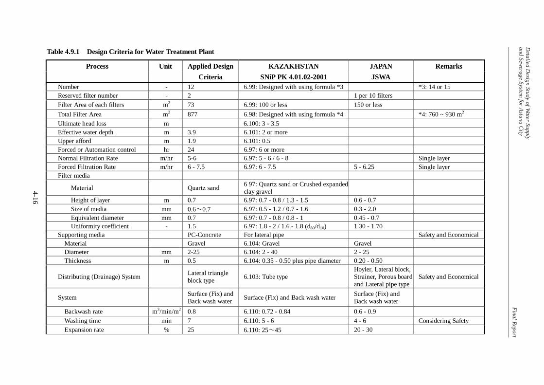
The design criteria for water treatment plant and sewerage facility in SNiP and JWWA
(Japan) is attached in Table 4.9.1 and Table 4.9.2, respectively. Applied design criteria for
this project are also shown in the tables.

Detailed D
esign Study of Water Supply
and Sewerage System for Astana City
Final Report
4-14
Table 4.9.1 Design Criteria for Water Treatment Plant
Process Unit Applied Design KAZAKHSTAN JAPAN Remarks Criteria SNiP PK 4.01.02-2001 JSWA
Intake Pump Station Number of compartment basin 2 5.88: more than 2 -
Location of intake mouth m 0.5m higher than bottom 5.96: 0.5m higher than bottom Lower than Low water
level
m 0.2m lower than the lower surface of ice
5.96: 0.2m lower than the lower surface of ice
Lower than Low water level
Inlet Velocity m/sec 1.0 5.106: not exceed 1.0 1 - 2 with fish protection equipment
m/sec - 5.94: 0.1 - without fish protection equipment
Stand-by pump number - 2 7.3: 2 1 Transmission pipeline number - 2 7.6: 2 -
Water Treatment Facility Distribution Basin No Description Number of basins basin 1 - - Detention time min 3.7 - - Water depth m 6 - - Receiving Well No Description Number of wells basin 2 - Detention time min 1.8 - 1.5 or more Water depth m 5.2 - 3.0 - 5.0 Rapid Mixing Basin
Type Hydraulic Hydraulic, Mechanical Hydraulic, Mechanical
Number basin 2 6.44: 2 or more - Detention time min 2.1 - 1 - 5 G value sec-1 112 - -

Detailed D
esign Study of Water Supply
and Sewerage System for Astana City
Final Report
4-15
Table 4.9.1 Design Criteria for Water Treatment Plant
Process Unit Applied Design KAZAKHSTAN JAPAN Remarks Criteria SNiP PK 4.01.02-2001 JSWA
Flocculation Basin: Buffle Type Detention time min 27.4 6.54: 20 - 30 20 - 40 G Value sec-1 60 - 10 - 75 GT Value - 98,310 - 23,000 - 210,000 Velocity m/sec 6.54: 0.2- 0.3 (beginning) 0.15 - 0.30 m/sec 6.54: 0.05 - 0.1 (end) Corridor Width m 0.8-1.2 6.54: 0.7 or more - Turn Number - - 6.54: 8 - 10 - Adjust by G value Horizontal Sedimentation Basin Number basin 6 - 2 or more Width m 9 6 m or less - Water Depth m 5.0-4.0 6.68: 6 or less 3 - 4 Effective settling zone height m 4.0 6.68: 3 - 3.5 - Sludge Depth m 0.5 - 0.3 Upper Space m 0.6 6.73: 0.3 or more 0.3 Surface Loading mm/min 27 6.56: 21 - 27 15 - 30 Velocity m/min 0.34 6.68: 0.36 - 0.48 0.4 or less Required Area m2 2,760 6.67: Designed with using formula *1 *1: 2,930 ~ 3,950 m2 Length m 50 6.68: Designed with using formula *2 *2: 33.3 ~ 70.0 m Trough Loading m3/day/m 350 - 500 or less Length m 4.2 6.75: 2/3 of settling tank Distances between axis of pipes m 1.5 6.75: 3 or more Top of trough cm 10 6.75: 10 over HWL Opening cm 6.75: 5 - 8 above the bottom Opening dia mm 25 6.75: 25 or more Opening m/sec 6.75: 1 Rapid Sand Filter
Detailed D
esign Study of Water Supply
and Sewerage System for Astana City
Final Report
4-16
Table 4.9.1 Design Criteria for Water Treatment Plant
Process Unit Applied Design KAZAKHSTAN JAPAN Remarks Criteria SNiP PK 4.01.02-2001 JSWA
Number - 12 6.99: Designed with using formula *3 *3: 14 or 15 Reserved filter number - 2 1 per 10 filters Filter Area of each filters m2 73 6.99: 100 or less 150 or less Total Filter Area m2 877 6.98: Designed with using formula *4 *4: 760 ~ 930 m2 Ultimate head loss m 6.100: 3 - 3.5 Effective water depth m 3.9 6.101: 2 or more Upper afford m 1.9 6.101: 0.5 Forced or Automation control hr 24 6.97: 6 or more Normal Filtration Rate m/hr 5-6 6.97: 5 - 6 / 6 - 8 Single layer Forced Filtration Rate m/hr 6 - 7.5 6.97: 6 - 7.5 5 - 6.25 Single layer Filter media
Material Quartz sand 6 97: Quartz sand or Crushed expanded clay gravel
Height of layer m 0.7 6.97: 0.7 - 0.8 / 1.3 - 1.5 0.6 - 0.7 Size of media mm 0.6~0.7 6.97: 0.5 - 1.2 / 0.7 - 1.6 0.3 - 2.0 Equivalent diameter mm 0.7 6.97: 0.7 - 0.8 / 0.8 - 1 0.45 - 0.7 Uniformity coefficient - 1.5 6.97: 1.8 - 2 / 1.6 - 1.8 (d80/d10) 1.30 - 1.70 Supporting media PC-Concrete For lateral pipe Safety and Economical Material Gravel 6.104: Gravel Gravel Diameter mm 2-25 6.104: 2 - 40 2 - 25 Thickness m 0.5 6.104: 0.35 - 0.50 plus pipe diameter 0.20 - 0.50
Distributing (Drainage) System Lateral triangle block type 6.103: Tube type
Hoyler, Lateral block, Strainer, Porous board and Lateral pipe type
Safety and Economical
System Surface (Fix) and Back wash water Surface (Fix) and Back wash water Surface (Fix) and
Back wash water
Backwash rate m3/min/m2 0.8 6.110: 0.72 - 0.84 0.6 - 0.9 Washing time min 7 6.110: 5 - 6 4 - 6 Considering Safety Expansion rate % 25 6.110: 25~45 20 - 30

Detailed D
esign Study of Water Supply
and Sewerage System for Astana City
Final Report
4-17
Table 4.9.1 Design Criteria for Water Treatment Plant
Process Unit Applied Design KAZAKHSTAN JAPAN Remarks Criteria SNiP PK 4.01.02-2001 JSWA
Rapid Sand Filter Surface wash rate m3/min/m2 0.2 6.110: 0.18~0.24 0.05 - 0.10 Surface washing time min 5 6.110: 5 - 8 4 - 6 Surface wash head m 20 6.110: 30~40 10~20 Sludge treatment Drainage Basin Number basin 2 App 9.2: 2 or more 2 or more
Volume per a basin m3 1,260 App 9.2: one backwash volume or more one backwash volume or more
Water depth m 3 - 2 - 4 Upper height m 1.5 0.6 or more Thickener Number basin 2 - 2 or more Diameter m 18 App 9.9: 18 or less - Water depth m 3.5 App 9.9: 3.5 or more 3.5 - 4.0 Upper height m 0.3 0.3 Retention Time hr 16 App 9.11: 10 24 - 48 Sludge loading kg/m2/day 20 - 10 - 20 Sludge Drying Beds Number of beds - 6 - 2 or more Water depth m 1.0 - 1 or less Upper height m 0.5 0.5

Detailed D
esign Study of Water Supply
and Sewerage System for Astana City
Final Report
4-18
Table 4.9.2 Design Criteria for Sewerage Facilities
Process Unit Applied Design KAZAKHSTAN JAPAN Remarks Criteria SNiP 2.04.03-1985 JSWA
Sewer Pipe/Pump Station Sewer Pipe
Minimum Flow m/sec 0.4 2.35: 0.4 0.6
Maximum Flow (1) m/sec 8 2.36: 8 Metal Pipe Maximum Flow (2) m/sec 4 2.36: 4
3 Nonmetal Pipe
Minimum Diameter (1) mm 200 2.33: Dia 200 Street Minimum Diameter (2) mm 150 2.33: Dia 150 Neighborhood Domestic Minimum Diameter (3) mm 150 2.33: Dia 150
Dia 200 Sludge Pipe
Pump Station Stand-by Pumps unit 2 5.4: 2 1 Category I *) Number of Pressure Pipeline number 2 5.8: 2 - Category I *) Wastewater Treatment Inflow Design Maximum Flow Ratio - 1.47 2.7: 1.47 1.3 - 1.8 For 1,000 L/s Grit Chamber Type Vortex Vortex - Number of basins basin 2 - - Hydraulic Load m3/m2/day 5000 - - Retention Time sec 15 - - Primary Sedimentation Tank No Description Type Radiation Radiation Radiation Number of tanks basin 8 6.58: 2 or more 2 or more Hydraulic Load m3/m2/day 30 6.60 - 6.62: 30 by calculation 35 - 70

Detailed D
esign Study of Water Supply
and Sewerage System for Astana City
Final Report
4-19
Table 4.9.2 Design Criteria for Sewerage Facilities
Process Unit Applied Design KAZAKHSTAN JAPAN Remarks Criteria SNiP 2.04.03-1985 JSWA
Water depth m 3.5 1.5 - 5 2.5 - 4 Retention Time hr 1.5 - 1.5 Aeration Tank
Type Conventional Activated Sludge Conventional Activated Sludge Convention Activated
Sludge
Number of tanks basin 4 - 2 or more Water depth m 4 6.150: 3 - 6 4 - 6 Retention time hr 8 6.144 - 6.146: by calculation 6 - 8 Secondary Sedimentation Tank Type Radiation Radiation Radiation Number of tanks basin 12 - 2 or more Hydraulic Load m3/m2/day 25 6.161: 25 by calculation 20 - 30 Water depth m 4 1.5 - 5 2.5 - 4 Retention Time hr 2 - - Gravity Thickener Type Radiation Radiation Radiation Number of tanks basin 2 6.343: 2 or more 2 or more Water depth m 3.5 - Approximately 4m Retention Time hr 12 - 15 6.344: 12 - 15 - Solid Load kg/m2/day - - 60 - 90 Digester Type Thermophilic Thermophilic Type Thermophilic Type Number of tanks basin 3 - 2 or more Diameter m 17.5 - 10 - 30

Detailed D
esign Study of Water Supply
and Sewerage System for Astana City
Final Report
4-20
Table 4.9.2 Design Criteria for Sewerage Facilities
Process Unit Applied Design KAZAKHSTAN JAPAN Remarks Criteria SNiP 2.04.03-1985 JSWA
Water Depth m 8 6.356: Diameter to Depth: not less than 0.8 to 1
Diameter to Depth: Approximately 2 to 1
Daily Rate of Loading % 17 6.350: 17 - Thickened Sludge 95%
Retention Time day 6 6.350: 6.0 (calculated by above item) Approximately 20days
Gas Holder Retention Time hr 2 - 4 6.359: 2 - 4 12 Sludge Dewatering Unit Stand-by Units unit 2 6.385: 2 1 Working Unit Number: 3 Top of trough cm 10 6.75: 10 over HWL Opening cm 6.75: 5 - 8 above the bottom Opening dia mm 25 6.75: 25 or more Opening m/sec 6.75: 1
Note *): In case of the halt and decrease of sewage discharge are not admitted.

CHAPTER 5 WATER SUPPLY FACLITIES

Detailed Design Study of Water Supply and Sewerage System for Astana City Final Report
5-1
CHAPTER 5 WATER SUPPLY FACILITIES
5.1 Intake Facility
5.1.1 Design Conditions
(1) Confirmation on the recommendations in F/S
1) “The need of a new intake P/S” (4.4.1 (1), 4-7 F/S)
Pumps and motors were replaced after F/S, however, deterioration of the facilities is
noted. There is a difficulty to operate the facilities to meet the fluctuation of demand.
Manual control of flow rate also makes it difficult due to too large capacity of each pump.
Current flow control by discharge valve has caused energy losses requiring additional
power cost.
It was analyzed that the combination use of No. III transmission pipeline (diameter of
1400 mm) and No. II pipeline has enough capacity to lessen the required head of intake
pumps. Namely, such a combination use of the two pipelines and introduction of less
head pumps allow the pump station to save considerable power cost.
For automatic flow control and operational cost saving, provision of new
pumps/equipment and construction of concerned facilities are requisites.
2) “Locational restriction of a new intake facilities under sanitary buffer zone.” (4.4.1 (1),
4-7 F/S)
In Chapter 10, SNiP (PK 4.01.02-2001), provision of sanitary protection zones is stated to
protect water resource from contamination, indicating that any kind of construction work
shall not be allowed within the first zone, i.e. the area in a circle with a radius of 100m at
the origin of existing intake P/S in case of water source reservoir. The location of the
P/S recommended in the F/S was examined and re-arranged based on the results of
topographic survey and soil investigation.
3) Intake Pump Capacity
F/S proposed that the capacity of new intake pumps required should be 200,000 m3/day,
which is same as existing ones, though their present capacity is much more than the
requirement.

Detailed Design Study of Water Supply and Sewerage System for Astana City Final Report
5-2
The present nominal capacity of existing water treatment plant, however, is 200,000
m3/day. It is decided that the treatment capacity of WTP should maintain the capacity,
even after completion of a new plant. Considering water loss in the transmission
pipeline, additional water amount with 5 % of the water treatment capacity is assumed;
Intake amount arrived at 210,000 m3/day (200,000 m3/day x 1.05).
4) Location of Equipment
In the F/S, location of electrical equipment is planned to install on the ground floor of the
intake pump station. This arrangement will contribute not only for ease of operation but
also for safety of equipment against inundation. Location of pumps shall be at the pump
room below the low water level of the reservoir due to easy and reliable starting without
pump priming unit.
5) Type of Inlet
The water quality in the Vyacheslavsky reservoir shows the sign of eutrophication. In
addition, the change of water level in the reservoir is large. Water quality of reservoir
usually differs by water depth; therefore suitable depth for water intake shall be selected
considering seasonal and hydrological conditions. Because of these reasons,
multi-intake ports is applied for the intake P/S, as proposed in F/S.
6) Intake tower structure
The caisson construction method is commonly used for this kind of construction work in
water as proposed in the F/S. It was also confirmed that the caisson method is popular
for the construction of sewage intermediate pumping stations in Kazakhstan. Therefore,
the caisson method is applied and detailed design was prepared referring to the results of
soil survey at the site.
(2) Considerations on SNiP
In SNiP (PK 4.01.02-2001), following requirements are stipulated to formulate the function
of water facilities.
・ Item 5.88: Inside of water receiving facilities shall be divided into two or more
compartments, and equipment to prevent ice scum and garbage shall be provided.
・ Item 5.96: Intake mouth shall be set at 0.5 m higher than the bottom level of the
reservoir and also 0.2 m lower than the lower surface of ice cover.

Detailed Design Study of Water Supply and Sewerage System for Astana City Final Report
5-3
・ Item 5.97: Equipment to remove ice or ice scum shall be considered.
・ Item 5.106: Inlet speed at the low water level shall not exceed more than 1 m/sec
when fish protection equipment will be installed. If not, it shall be less than 0.1
m/sec.
・ Item 7.3: Intake pumps shall be installed with two units of stand-by.
・ Item 7.6: Transmission pipeline shall be installed double.
(3) Considerations on other conditions
1) Request by ASTANA SU ARNASI (ASA)
・ Structural arrangement of the intake facilities shall be made so that the intake
capacity can be increased easily in the future.
・ The influence to the existing intake facility by turbid water generated during
construction stage shall be minimized.
2) Request by ISHIM RIVER BASIN DEPARTMENT
Isim River Basin Department, the management agency of the Vyacheslavsky reservoir,
requested the following:
・ The facility to protect fish shall be provided for intake at the P/S.
3) Operation Methodology for Existing and New Pump Station
The transmission pipelines of No. III (D1400mm) and No. II (D1000mm) should be used
simultaneously for operation of new pump station. The management of the existing
intake water facilities shall be properly done for emergency use after construction of new
intake facilities.
5.1.2 Design Policy
As a result of discussions among concerned parties and considerations stipulated above,
following design policies were established for the new intake facilities.
(1) Capacity
Design intake capacity shall be 210,000 m3/day including 5 % of water loss in the
transmission pipeline to meet nominal treatment capacity of WTP, 200,000 m3/day.
Detailed Design Study of Water Supply and Sewerage System for Astana City Final Report
5-4
(2) Layout
Location of P/S affects to the cost, especially for excavation of an intake channel and
construction of an access road. Regulation stipulated in SNiP, however, does not allow
construction of the proposed P/S within 100 m radius from the existing P/S because the
proposed P/S is not considered as an expansion of existing P/S.
Figure 5.1.1 shows the locations of existing facilities and topography around the existing P/S.
As shown in the figure, the location of the new P/S was examined at three candidate sites
toward east of the existing P/S. Location of new P/S was finally determined at just outside
of the sanitary buffer zone.
(3) Facilities
New intake P/S shall be facilitated with a staff room and an electric room at the upper
architectural part. Its submerged portion shall be made of RC structure to accomodate pump
room and multi-storied intake mouths.
Electrical equipment shall be arranged on the ground floor, above reservoir’s surcharge water
level. Since the new P/S is constructed in the reservoir, an access road is necessary.
(4) Design Water Level
During the B/D stage, JICA Study Team received the information about operation rule of the
Vyacheslavsky reservoir from the Ishim River Basin Department, Committee for Water
Resources, Ministry of Agriculture as follows:


Detailed Design Study of Water Supply and Sewerage System for Astana City Final Report
5-6
• Maximum Water Level (surcharge level): 404.40m
• Normal Water level: 403.00m
• Low Water Level: 391.00m
Above water levels are applied in the detailed design with following planned floor levels:
• Structure Bottom Level: 387.00m (equal to bottom level of existing P/S)
(5) Others
During construction period, the excavation method minimizing water contamination shall be
adopted and additionally some turbid water protection measures shall be introduced such as
enclosing by silt protection sheets.
The new intake facility shall be connected to existing water transmission pipeline No. III, and
No. II through interconnection pipes.
Main body shall be set at the O1a layer, which has been confirmed its 100 ton/m2 of bearing
capacity during F/S stage. The level of foundation layer was decided after the soil survey in
this study and a stability calculation for main structure.
5.1.3 Design Details
(1) General
The difference between high and low water level, 13.4 m as maximum, is large, and
inclination of ground under the water level is small. Therefore, it is costly to locate the
intake facility on the shore requiring high cost for excavation of a water intake channel.
Considering these conditions, the location of the new intake facility was decided in the
reservoir as mentioned above.
Asphalt paved access road with a length of about 280m will be constructed between existing
access road near existing P/S and the proposed intake tower.
An electrical room, control room, staff room and equipment loading space will be provided in
the New P/S.
A sub-station building (approximately 15 m x 9 m) was designed next to the existing power
sub-station and new electric cables will be installed in a conduit provided along new access
road. Detailed description of the proposed electrical equipment will be given in the relevant
section. In addition, a guard house and a surge control house was designed for the new P/S.

Detailed Design Study of Water Supply and Sewerage System for Astana City Final Report
5-7
(2) Structure
1) Construction Method
A comparison of construction methods for main structure/tower is presented in Table 5.1.1.
As shown in the table, it is recommendable that the main body shall be constructed by the
open caisson method because of following reasons:
・ Major construction work shall be conducted in water-surrounded circumstances.
・ Open caisson method is popular in Astana.
The shape of plan should be circle because of introduction of the caisson method.
The structure of the P/S was decided taking into account of adopted pump type (dry type).
Main points of consideration are as follows:
• Possible introduction of submergible pumps was examined, but it was concluded that
such a pump type is not appropriate for large capacity P/S like this project. Thus,
inside of the tower shall be kept dry to install dry type pumps. To ensure the smooth
water intake, inlet piping shalll be provided from inlet mouths to pumps.
• Dimensions of structures including diameter of the tower and level of floors are
designed to accommodate pumps and piping on the basement and motors on the
ground floor, and to secure enough openings to install larger pumps, valves and pipes.
• One opening will be provided on the floor for installation of pumps and other
materials. Pumps shall be handled with hoists provided at beam.
2) Arrangement of rooms and equipment
Electric rooms, control room, staff room and equipment loading space were designed to be
located above the flood water level. Considering the installation space for electric cables,
the floor level of these rooms was set at +409.00 m, 4.6 m above the normal water level.
Raw water will be pumped through an integrated header pipe in a core column and two
discharge pipelines. Two butterfly valves are provided to enable a single transmission
pipeline to send design water to WTP in case of emergency. Traveling hoists are installed
over equipment loading space and in the pump room to ease loading and installation of
equipment.

Detailed D
esign Study of Water Supply
and Sewerage System for Astana City
Final Repor t
5-8
Table 5.1.1 Comparison of Construction Methods for Intake Tower
Caisson Method Item Open Caisson Pneumatic Caisson
Double Sheet Pile Cofferdam Cast-in-situ Diaphragm Wall
Conceptual Drawing
Advantage
Many P/S were constructed by this method in Astana. Less cost Suitable for geologicl condition of the site. Suitable for planned depth.
Deep structure can be constructed. Perfect water intrusion prevention.
Popular method. Relatively high cost. Rectanglar shape can be adopted.
Safe construction work. Diaphragm wall can be used as wall of main body. Rectanglar shape can be adopted.
Disadvantage
Shape is restrected as circle or oval. Construction ground is required in the Reservoir.
Higher cost. Advanced construction management technology is required. Long construction period. It is not necessary when open caisson method can be adopted
Difficult to drive sheet pile to bedrock or hard soil layer.
High Cost. Hard to construct diaphragm wall in bedrock. Long construction period.
Cost 100 120 100 (Difficult to construct) 150 Judgement Adopt

Detailed Design Study of Water Supply and Sewerage System for Astana City Final Report
5-9
3) Pump Room
A circular shape structure plan was selected for the new intake tower. The inside diameter
of the tower was designed at 20 m considering that the pump number required is six including
two stand-by and a room for two pumps in the future. The distances between pump casings
are secured at around 3m and the distance between a pump casing and wall is about 3m from
the core column wall and 4m from the peripheral wall.
(3) Specification of Pumps
Intake pump capacity is influenced greatly by the operation method of the facility. Water
levels at the reservoir and the water treatment plant as well as differences between the two
facilities are shown in Table 5.1.2.
A transmission pipeline No.3 of D1400mm is being used presently. However, another
pipeline No.2 of D1000mm can be used together with the No.1 pipeline after rehabilitation by
ASA. The design of new intake pump must be prepared taking into consideration economy
and operational efficiency. By using the two pipelines simultaneously, required pump head
can be reduced considerably.
Table 5.1.2 Water Level of Reservoir and Water Treatment Plant
Water Level
Vyacheslavsky Reservoir Water Treatment Plant Difference
High Water Level: + 403.0 m +363.4 m - 37.6 m
Low Water Level: + 391.0 m +363.4 m - 27.6 m
Existing intake pump capacity is as follows: 6300 m3/hr x 95.0 mH x 1250 kW x 3 units
(stand-by 2 units).
Based on hydraulic calculations, water head losses of some cases utilizing No. III and/or No.
II pipelines and new/existing pumps are shown in Table 5.1.3. The total heads of new
pumps are 35 m and existing pumps are 90 m.
Table 5.1.3. Required Total Head in Each Case
Conveyance Pipeline
No. II (1000 mm) No. III (1400 mm)
New Intake
Pumps
Existing Intake
Pumps
Required Total
Head
O O O 35m
O O 90m
O O 450m*
* Only 100,000 m3/day of water can be sent with 90 m head.

Detailed Design Study of Water Supply and Sewerage System for Astana City Final Report
5-10
Based on the calculations, it was decided that new intake pumps shall be operated using two
raw water transmission pipelines of No. II and No. III, and the existing pump be operated in
case of emergency. The new pumps are utilized with low voltage motors, and an automatic
valve control system is also adopted to get the following advantages.
・ Reduction of operation cost by remarkable saving of electricity consumption.
・ Reduction of initial cost.
・ Prolonging lifetime and reduction of leakage of pipelines under the operation of
distribution system with low-water pressure.
・ Precise and easy operation by automatic valve control system.
Six units of intake pumps including two units of stand-by will be installed according to the
requirements by SNiP. The capacity of new intake pump is as follows (Details shall be
referred to in Section 5.7 Mechanical Facility): Pump specifications: 36.5 m3/min. x 35 m
head x 280 kW x 6 units (2 units stand-by).
In accordance with the requirement by SNiP, two raw water discharge pipeline with a
diameter of 1,400 mm (Steel Pipe) will be installed to connect the new intake tower and the
existing raw water transmission pipelines.
(4) Intake Mouth
Several intake mouths are provided at different elevations so that raw water from different
depth can be taken selecting better water quality in the reservoir. Installation of screen to
prevent from incoming of fish is obliged by SNiP and inflow velocity shall be less than 1
m/sec. Therefore, minimum area of intake gate was planned as 3 m2. A metal-seated
butterfly valve will be installed at each intake mouth.
(5) Construction Method
The open caisson method with soil mounding is applied for intake tower construction after
detailed examination of construction methods based on soil conditions.
The order of construction has been planned as following:
1) Install the curtain in the water for contamination protection in the surrounding area of
construction site.
2) Construct the access road and parking space.
3) Install temporary pier made of steel frames and lining plates in the surrounding point
of intake tower.

Detailed Design Study of Water Supply and Sewerage System for Astana City Final Report
5-11
4) Drive steel sheet piles in a circular alignment with a diameter of 35 m from the center
of Tower. These piles are sustained by H framed piles, which is driven in the
circular.
5) Fill up the inside of the circle with soil for the caisson construction.
6) Construct a bottom part of caisson on the ground.
7) Excavate the inside of caisson to sink the caisson down into ground. When the
bottom of caisson reaches at design level, the bottom is leveled and steel bars are
arranged and connected. Finally, base concrete will be casted.
8) Excavate filled soil between caisson outer surface and sheet piles.
9) Pull out and remove sheet piles and H frame.
10) Extend temporary pier and excavate channel for intake.
11) Construct the intake building during the excavation.
12) Remove temporary pier and construct a bridge from filled access road to the intake
tower.
13) Install mechanical and electrical equipment.
Openings of the tower for water intake shall be temporally closed by steel plate, and valves
shall be installed inside to prevent inflow of water during the construction work. To
minimize the contamination affected by turbidity to the raw water for existing P/S, plastic or
fabric submerged curtain and coagulant dosage shall be provided around the construction site
during the construction work.
(6) Connection Pipelines
In compliance with the regulation stipulated in SNiP, two connection pipelines will be
installed between a new intake pump station and existing raw water transmission pipelines.
Diameters of these connection pipelines are 1400mm. Both of these connection pipelines
shall be used simultaneously to prevent stagnation and freezing of water in the pipelines.
Minimum invert level will be kept at G.L.-2.8 m (refer to subsection 5.2.3). A flow meter
and a control valve shall be provided to control flow.
Figure 5.1.2 shows the conceptual plan of pipe connection. Though the two connection
pipelines are connected with the raw water transmission pipelines in compliance with the
regulation of SNiP, the part of the flow meter and the control valve shall be closed usually to
in order to secure effective and accurate flow control.

Detailed Design Study of Water Supply and Sewerage System for Astana City Final Report
5-12
ToExisting Raw WaerTransmissionPipelines
PControlValve
Flow -meter
: Flow Direction
P P
P P
P
Intake Pump Station P : Pump
Close for flow control
Figure 5.1.2 Connection between Intake P/S and Connection Pipeline
(7) Connection to Raw Water Transmission Pipelines
As mentioned above, new two connection pipelines (D1400mm x 2) will be installed for
connection between the intake P/S and existing raw water transmission pipelines Nos. II and
III. Water through the connection pipelines shall be smoothly flow into both of the existing
raw water pipelines. It shall also be considered that the existing intake P/S is used in case of
operation failure of new P/S.
Taking into account of such a requirement, the following plan was decided for connection
from P/S to raw water transmission pipelines.

Detailed D
esign Study of Water Supply
and Sewerage System for Astana City
Final Repor t
5-13
Figure 5.1.3 Connection from P/S to Raw Water Transmission Pipeline

Detailed Design Study of Water Supply and Sewerage System for Astana City Final Report
5-14
5.2 Raw Water Transmission Pipeline
5.2.1 Selection of Sections for Rehabilitation
As stated in previous Chapter, the rehabilitation work of the Raw Water Transmission
Pipeline No.2 was eliminated from the scope of work of the JBIC assisted Project as a result
of discussions between JBIC and the Kazakhstan side. Therefore, the Kazakhstan side shall
carry out the rehabilitation of the Raw Water Transmission Pipeline using their own fund.
During the basic design stage, however, the Study Team examined the leakage record from
1997 to 2002 together with field observation for the selection of priority sections for future
rehabilitation work to be done by Kazakhstan side.
It was summarized that most leakages were found at several parts of the pipeline as shown on
Figure 5.2.1. Thus, four (4) sections with a total of 15 km are designated for rehabilitation
as follows:
Section 1: 1.5 km
Section 2: 7.5km
Section 3: 2.5km
Section 4: 3.5km
Total 15.0km
Schematic plan of sections of the pipeline for rehabilitation is also presented in Figure 5.2.1.
5.2.2 Rehabilitation Work
Rehabilitation work of the pipeline in the designated sections is to replace the existing pipes
with new pipes using local fund of Kazakhstan.
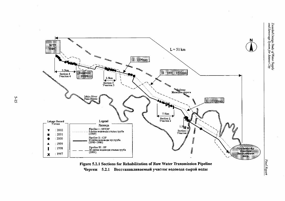

Detailed Design Study of Water Supply and Sewerage System for Astana City Final Report
5-16
5.2.3 Topographic and Hydraulic Conditions
Longitudinal profile of the pipeline route from the Intake P/S to the WTP is shown in Figure
5.2.2. The figure also shows hydraulic conditions calculated in case of 210,000 m3/d
utilizing the two pipelines No. II and No. III simultaneously.
The calculation is as follows:
(1) Hydraulic Calculation Formula
Hazen-Williams’ formula is used for hydraulic calculation. This formula is very similar to
the equation presented in SNiP, and commonly used in the field of water works.
H = 10.666 x C-1.85 x D-4.87 x Q1.85 x L
H: Head loss (m)
C: C value (New pipe: 120, Old pipe: 110)
D: Pipe diameter (m)
Q: Water flow (m3/s)
L: Pipeline length (m)
(2) Invert Level
Based on “SNiP: 4.01-02-2001-8.42 PUBLIC WATER SUPPLY SYSTEMS AND
STRUCTURES” and “Reference Manual to SNiP - Construction Climatology”, invert level
of underground pipes shall be lower than -2.8 m deep.
Pipeline
More than 0.5 m
0°C temperature penetration depth: 2.3m*
Invert level shall be lower than GL-2.8m
* Astana is located within contour line of 230cm of 0°C temperature penetration depth in SNiP.
Ground Level
(3) Result of Calculation
As a result of hydraulic calculation for a flow of 210,000 m3/d under some cases; each
individual pipeline, No.II and III, and as a single pipeline in combination of the both lines, no
Detailed Design Study of Water Supply and Sewerage System for Astana City Final Report
5-17
negative pressure is observed for whole the pipeline length in each calculation. The result of
calculation is also shown on Figure 5.2.2.
5.2.4 Measures against Water Hammer Phenomenon
This section presents the recommendation for design work, especially against a water hammer
phenomenon.
(1) Water Hammer
As analyzing characteristics of the transmission pipelines, operation/control of the pump
station was examined. The pipelines were often damaged by the surge phenomenon due to
the irregular installation level and poor measures against the phenomenon.
Loss of power supply to the boosting system will cause surging and water hammer in the
transmission pipeline.
When flow velocity in the pipeline changes within a short period, the water pressure in the
pipeline changes rapidly. If the pressure becomes negative, the water in the pipe may
evaporate forming cavities and causing water column separation, which intensifies the
pressure on collapse of the cavity. This phenomenon is called a water hammer and the
intensity depends on many factors such as pipe length, pump characteristics, etc. Measures
for preventing water hammering must be taken to prevent damages of pipelines.
(2) Conditions for Analysis
Conceivable methods for preventing water hammer are as follows:
• Providing a flywheel to the pump
• Installing a surge tank (conventional/one-way) in the pipeline
• Installing a pressure water tank (air vessel) at the pump and/or pipeline
In consideration of the magnitude of the water mass in the pipeline, the option to use a
flywheel will not be applied because the size of the required flywheel will be too big to start
pumps. A surge tank system is practicable. At present, pipeline No. III is connected to a
one-way surge tank with a capacity of 1,000m3 located at the peak 5.2km far from the WTP.
But this tank is not used because of a trouble of inlet float valves. A pressure water tank
may be used as a suitable option.
Longitudinal profile of the pipeline route from the Intake P/S to the WTP is shown in Figure
5.2.3. The figure includes water pressure gradient in case of 210,000m3/d transmission
using pipelines No. II and No. III.

Detailed D
esign Study of Water Supply
and Sewerage System for Astana City
Final Report
5-18
350
360
370
380
390
400
410
420
430
440
450
0 5,000 10,000 15,000 20,000 25,000 30,000 35,000 40,000 45,000 50,000 55,000
WTP НФС WL=+363.4m Уровень воды
Reservoir Водохран. HWL=+403.0m Мак.уровень LWL=+391.0m Мин.уровень
Pipeline III (1400mm) Водовод III (1400мм)
Pipeline III (1000mm) Водовод III (1000мм)
Pipeline II (1000mm) Водовод II (1000мм)
Ground Level Уровень земли
Pipe Invert Level Уровень дна трубы
Distance (m) Дистанция (м)
Level (m) Уровень (м)
FiFiFiFigure 5.2.2 Longitudinalgure 5.2.2 Longitudinalgure 5.2.2 Longitudinalgure 5.2.2 Longitudinal Profile of Raw Water Transmission PipelineProfile of Raw Water Transmission PipelineProfile of Raw Water Transmission PipelineProfile of Raw Water Transmission Pipeline ЧертежЧертежЧертежЧертеж 5.2.2 5.2.2 5.2.2 5.2.2 ПродольныйПродольныйПродольныйПродольный профильпрофильпрофильпрофиль прокладкипрокладкипрокладкипрокладки водоводовводоводовводоводовводоводов
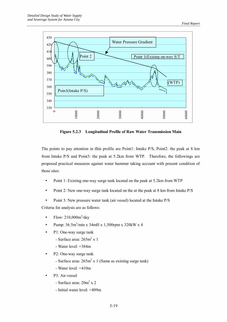
Detailed Design Study of Water Supply and Sewerage System for Astana City Final Report
5-19
330
340
350
360
370
380
390
400
410
420
430
0
1000
0
2000
0
3000
0
4000
0
5000
0
6000
0
Figure 5.2.3 Longitudinal Profile of Raw Water Transmission Main
The points to pay attention in this profile are Point1: Intake P/S, Point2: the peak at 8 km
from Intake P/S and Point3: the peak at 5.2km from WTP. Therefore, the followings are
proposed practical measures against water hammer taking account with present condition of
those sites:
• Point 1: Existing one-way surge tank located on the peak at 5.2km from WTP
• Point 2: New one-way surge tank located on the at the peak at 8 km from Intake P/S
• Point 3: New pressure water tank (air vessel) located at the Intake P/S
Criteria for analysis are as follows:
• Flow: 210,000m3/day
• Pump: 36.5m3/min x 34mH x 1,500rpm x 320kW x 4
• P1: One-way surge tank
- Surface area: 265m2 x 1
- Water level: +384m
• P2: One-way surge tank
- Surface area: 265m2 x 1 (Same as existing surge tank)
- Water level: +410m
• P3: Air-vessel
- Surface area: 20m2 x 2
- Initial water level: +409m
Poin3(Intake P/S)
Point 2 Point 1(Exising on-way S/T
(WTP)
Water Pressure Gradient

Detailed Design Study of Water Supply and Sewerage System for Astana City Final Report
5-20
• Time for calculation: 500sec.
(3) Results of Analysis
The following five (5) cases were studied.
• Case 1 No countermeasure is provided
• Case 2 P1: Existing one-way surge tank only
• Case 3 P1: Existing one-way surge tank + P2: New one-way surge tank
• Case 4 P1: Existing one-way surge tank + P3: Air-vessel at intake
• Case 5 P1: Existing one-way surge tank + P2: New one-way surge tank
+ P3: Air-vessel at intake
Results of analysis are shown as follows:
1) Case 1: Large negative pressure is occurred through all pipeline length.
330
340
350
360
370
380
390
400
410
420
430
0
1000
0
2000
0
3000
0
4000
0
5000
0
6000
0
Figure 5.2.4 Case 1: No Measure is Provided
Lowest

Detailed Design Study of Water Supply and Sewerage System for Astana City Final Report
5-21
2) Case 2: Downstream of Point 1 has no problem, while a large negative pressure is observed upstream of Point 1
330
340
350
360
370
380
390
400
410
420
4300
10000
20000
30000
40000
50000
60000
Figure 5.2.5 Case 2: P1 - Existing One-Way Surge Tank
3) Case 3: Downstream of Point 2 has no problem. But, a large negative pressure is occurred upstream of Point 2.
330
340
350
360
370
380
390
400
410
420
430
0
1000
0
2000
0
3000
0
4000
0
5000
0
6000
0
Figure 5.2.6 Case 3: P1 - Existing One-Way Surge Tank + P2 - New One-Way Surge
Tank

Detailed Design Study of Water Supply and Sewerage System for Astana City Final Report
5-22
4) Case 4: Downstream of Point 1 has no problem. But, negative pressure on the Point 1 and Point 2 cannot be canceled due to small size of air vessel.
330
340
350
360
370
380
390
400
410
420
430
4400
1000
0
2000
0
3000
0
4000
0
5000
0
6000
0
Figure 5.2.7 Case 4: P1 - Existing One-Way Surge Tank + P3 - Air-Vessel at Intake P/S
5) Case 5: There is no problem along the pipeline route in this case.
330
340
350
360
370
380
390
400
410
420
430
0
1000
0
2000
0
3000
0
4000
0
5000
0
6000
0
Figure 5.2.8 Case 5: P1 - Existing One-Way Surge Tank + P2 - New One-Way
Surge Tank + P3 - Air-Vessel at Intake P/S

Detailed Design Study of Water Supply and Sewerage System for Astana City Final Report
5-23
(4) Recommended Measures
According to the above-mentioned examinations, measure proposed in Case 5 is
recommendable against water hammer caused by sudden stop of intake pump. Among the
required facilities, the air-vessel at the point 3 is proposed for the Project as auxiliary facility
for new intake pumps. The one-way surge tank at the point 2, however, shall be constructed
together with the rehabilitation work of the raw water transmission pipeline No. II. In
addition, the one-way surge tank at the point 1 shall also be rehabilitated.
Instead of providing the new one-way surge tank at the point 2, provision of air valves at
peaks of pipelines stretching over all section will be an alternative plan. This alternative,
however, is not recommendable because of unreliability of functioning of air valves,
especially in a winter season.
As a result of the examination, the JICA team strongly recommend that the one-way surge
tank at the point 2 be constructed together with the rehabilitation work of the raw water
transmission pipeline No. II and existing surge tank at the point 1 before operation of the
proposed P/S.

Detailed Design Study of Water Supply and Sewerage System for Astana City Final Report
5-24
5.3 Water Treatment Plant
5.3.1 Recommendations in F/S
(1) “To meet the water demand for the year 2010, a capacity of approximately 100,000 m3/day of
additional WTP should be constructed to recover the lost capacity at the existing plant.”
A new WTP with a capacity of 100,000 m3/day is needed to cope with increase of demand
and with decrease of existing plant’s capacity.
(2) “The existing WTP will continue operations until the commissioning of the New WTP (No.3)
which is intend to replace WTP No.1.”
Existing plant shall not be abolished until new plants with sufficient capacity are to be
completed. Existing facilities, however, shall be rehabilitated one after another to maintain
their capacities at some level. This rehabilitation work is out of scope of this project.
(3) “Proposed Water Treatment Facilities for New Water Treatment Plant”
Outlines of proposed water treatment facility in F/S is presented in Table 5.3.1. Considering
raw water quality and planned treatment capacity, proposed process in F/S is regarded
appropriate. Treatment method conforms to regulation of SNiP.
Table 5.3.1 Outlines of Proposed Water Treatment Facilities
Name of Facility Type
Receiving Well RC Rectangular Tank
Rapid Mixing Tank Hydraulic Mixing Type
Flocculation Tank 3 Step Horizontal Flow Type
Sedimentation Basin Horizontal Flow Type with Sludge Collector
Rapid Sand Filter Down Flow Type
Administration Building RC, 3 stories
Distribution Pump Building RC, Ground and basement floors
(4) ”Proposed Automatic Operation and Monitoring System”
Automatic operation is applied to the Rapid Sand Filter for filtering and backwashing
processes, and to distribution pumps for speed control by discharge pressure. As for
monitoring, major operating information is monitored at the Central Monitoring Room in the
administration building.

Detailed Design Study of Water Supply and Sewerage System for Astana City Final Report
5-25
(5) “Buffer zones”
Required buffer zones specified in SNiP shall be secured.
5.3.2 Design Policy
As a result of discussions and consideration stipulated above, following design policies were
established for the new water treatment facility:
(1) Treatment Capacity
Treatment capacity of the new plant is 100,000m3/day. All facilities were designed based on
that capacity. Facilities from receiving wells to filters, however, were designed for
105,000m3/day taking account of production loss.
(2) Water Treatment Method
Regarding treatment method, the clause 6.10 of SNiP 2.04.02-84 recommends following two
methods against present raw water quality and planned treatment capacity:
!"Horizontal Sedimentation Tanks – Rapid Filters
!"Contact Pre-filters – Rapid Filters (two-step filters)
The latter method employs meshed drum filters, and it is not recommendable because it is
expected that the meshed drum filter be easily clogged with algae in the eutrophicated
reservoir water.
The method composed of up-flow reactor clarifiers and rapid filters is not recommendable
because of low turbidity of raw water except the snow-melting season.
Existing plant employed former method and accomplished rather good treatment results.
Considering regulation of SNiP and present performance of the existing plant, the former
method is adopted.
(3) Wastewater and Sludge Treatment Method
At present, backwash water from filters and drainage from sedimentation basins are
discharged to the river without treatment. It, however, shall not be discharged to the river
without treatment because of environmental reason. Because of this reason, wastewater and
sludge treatment facilities shall be provided in the Project.
Upon completion of the Project, all backwash water from existing and new filters will be sent
back to a distribution well through a washing drain basin, which buffers shock load caused by

Detailed Design Study of Water Supply and Sewerage System for Astana City Final Report
5-26
backwashing.
Sludge drained from sedimentation basins of the new plant will be led to thickeners and
thickened sludge will be dried up at sludge drying beds. Supernatant of the thickener and
wastewater from the drying beds are led to a discharge pool and then discharged to a drain
pipeline. Washout wastewater with settled sludge from the existing plant will be led to the
sludge drying beds directly because settled sludge is compressed during one-year operation.
(4) Design Policy
The following principles was applied in the detailed design of proposed water treatment
facilities:
!"Present operation and maintenance situation shall be considered and full dependence
on mechanical equipment shall be avoided.
!"Economic aspects shall be considered important. Extravagant equipment shall not
be introduced.
!"Mechanization and automation are appropriate only where operations are not readily
accomplished manually, or where they greatly improve the reliability assuring safe
and stable water supply.
!"Hydraulically based devices that use gravity for works such as rapid mixing and
flocculation are preferred to mechanised and/or automated equipment in
consideration of the available favourable topography of the plant site.
!" Indigenous materials and products such as filter sand, gravels for concrete, concrete
products etc. that are easy and safe for use in construction should be used to reduce
costs, and to bolster the local economy and expand industrial development, as far as
they fulfill required characteristics and performance.
5.3.3 Design Details
(1) Design Capacity and Design Calculations
Treatment capacity is 100,000m3/day except facilities from receiving wells to filters, which
will be designed for 105,000m3/day taking account of production loss. Most of facilities
will be housed and equipped with heating system for ease of operation and maintenance in
winter season.
Approximate dimensions and structure of each facility is as shown in Table 5.3.2. These
dimensions are decided based on the design calculation taking into account of design criteria

Detailed Design Study of Water Supply and Sewerage System for Astana City Final Report
5-27
specified in SNiP. Adopted design criteria are summarized in Chapter 4. Design
calculations are attached as Appendix. Figure 5.3.1 shows the layout plan of proposed
facilities. Hydraulic profile of facilities and the process flow diagram are shown in Figure
5.3.2.
Table 5.3.2 Dimensions and Structures of Facilities
Facility Design capacity and structure Distribution chamber 10.2 m width x 10.0 m length x 7.4 m depth x 1 unit Receiving well 4.2 m width x 7.2 m length x 6.5 m depth x 2 basins Rapid mixing basin 4.2 m width x 4.2 m length x 4.3 m depth x 2 basins
Flocculation basin 9.0 m length x 1.2 m width x 3.7 m depth x 12 channels 9.0 m length x 1.5 m width x 3.7m depth x 12 channels 9.0 m length x 2.3 m width x 3.7 m depth x 12 channels
Sedimentation basin 9.0 m width x 50.0 m length x 4.0 m depth x 6 basins Rapid sand filter 5.8 m width x 12.6 m length x 12 filters x 118 m/day Chlorine mixing channel 2.8 m width x 50.0 m length x 3.8 m depth x 1 basin Distribution pump room (Existing) 12.0 m width x 78.0 m length Administration building 15.0 m width x 54.0 m length x 3 floors Washing drain basin 12.4 m width x 34.5 m length x 3.0 m depth x 2 basins Thickener 18.0 m diameter x 3.5 m depth x 2 basins Sludge drying bed 20.0 m width x 45.0 m length x 1.0 m depth x 6 beds Cake yard 20.0 m width x 30.0 m length Discharge pool 11.8 m width x 34.5 m length x 3.0 m depth x 2 basins Chemical room 12.0 m width x 23.4 m length x 3 floors Chlorination room included in the above room In-plant piping 75 - 1600 mm 5,350m Miscellaneous Paving, planting, gate and fencing, guard house, etc.
(2) Design Water Level
Design water levels in each facility were decided based on the hydraulic calculation attached
as Appendix. In the hydraulic calculation, water level of existing clearwater reservoir was
set at 357.0 m, and water level of the distribution chamber was set at 363.4m.
(3) Distribution Chamber
Raw water is transmitted with three raw water transmission pipelines. In order to control the
flow to existing, new and future plants, a distribution tank will be provided. The tank is
divided into three compartments at the outlet side of the tank, and weirs control the flow to
each plant.

Detailed D
esign Study of Water Supply
and Sewerage System for Astana City
Final Repor t
5-28
� �� �� �� �� �� �� �� �� �� �� � �
�� �� � �� �� �� �� �� �� �� � �� �� �� �� �� �� ��� �� �� �� �� �� �� �� � ����� ��
� �� �� �� �� �� �� �� �� �� �� � �
� �� � �� �� �� �� �� �� �� � �� �� �� �� �� �� ��� �� �� �� �� �� �� �� � �������
� �� �� �� �� �� �� �� �� �� �� � �
� �� � �� �� �� �� �� �� �� � �� �� �� �� �� �� ��� �� �� �� �� �� �� �� � ������� � �� � �� �� �� �� �� �� �� � �� �� �� �� �� �� ��� �� �� �� �� �� �� �� � �������
� �� �� �� �� �� �� �� �� �� �� � �
� �� �� �� �� �� �� �� �� �� �� � �� �� �� �� � �� �� �� �
� �� �� �� �� �� �� �� �� �� �� � � � �� �� �� �� �� �� �� �� �� �� � �
� �� �� �� �� �� �� �� �� �� �� � �� �� �� �� � �� �� �� �
� �� �� �� �� �� � �� � �
� �� �� �� �� �� �� �� �� �� �� � �
� �� �� �� �� �� � �� � �
� �� �� �� �� �� �� �� �� �� �� � �
� �� �� �� �� �� �� �� �� �� �� �� �
� �� �� � �� � ��� �� � � � �� � !� �
� �� �� �� �� �� �� �� �� �� �� �� �
� �� �� � �� � ��� �� � � � �� � !� �
� �� �� � �� � �� � "
� �� � � �� �� ‰
R‰K‰L‰@‰
D‰H‰
D‰@‰N‰
I‰E
‰V‰L‰
O‰Q‰@‰S‰
O‰Q‰N‰@‰̀
‰V‰L‰
O‰Q‰@‰S‰
O‰Q‰N‰@‰̀
‰@‰D‰
M‰I‰
N‰I‰R‰
S‰Q‰@‰
S‰I‰B‰
N‰O‰
E ‰H‰
D‰@‰N‰
I‰E
� #� � ��� �� �� "�� �� �� �� �� � �� �� �� ��� � "
� �� �� �� �� �� �� �� �� �� �� � �� �� �� �� � �� �� �� �
� �� �� �� �� �� � �� � �
� �� �� �� �� �� � �� � �
� �� �� �� �� �� �� �� "� !� � �� �� �� ��
� �� �� � �� � �� � �� �
� �� � � � �� � !� �
� �� �� � �� � �
� �� � �� �� �� �� ��
� �� �� �� �� �� �� �� �� �� �� �� � �� �� �� � ��
� �� � �� �� �� �� �� �� �� � �� �� �� �� �� � "
� �� � � �� ��
� #� �� �� �� �� �� ��� �� � �� $� � �� �� �� � �
� �� %� �� � &� �� �� �� � �
� �� %� �� � &� �� �� �� � �
� �� %� �� � &� �� �� �� � �
� �� %� �� � &� �� �� �� � �� �� %� �� � &� �� �� �� � �
� �� %� �� � &� �� �� �� � �
� �� %� �� � &� �� �� �� � �
� �� %� �� � &� �� �� �� � �
� �� �� �� �� �� �� �� �� �� �� � "�� �� � �� �� �� �� �� �� �� � �� �� �� �� �� � "
� �� � �� �� �� �� � "�� �� �� � �� !� � "
� �� �� �� �� �� �� �� �� �� �� � "�
� '� �� �� �� �� �� �� �� �� � �� !� � "
� �� �� �� ���� � �� !� � "
� �� �� �� �� � �� ��
� �� �� "�� �� �� ��
� � �� �� �� � "�� �� �� �� �� � �� �� � � �� �� �� � "�� �� �� �� �� � �� ��
� �� �� � �� �� �� �� �� �� �� �� �� �� �� � �
� � �� �� �� �� �� �� �� �� ��� �� �� �
� �� �� �� �� �� �� �� � ��� �� �� �� �
� �� #� �� ��� �� �� �� �� �� �� � �� �� ��
‰C‰E‰N‰E‰Q‰@‰L‰]‰N‰\‰J ‰P‰L‰@‰N
� �� �� �� ���� � �� !� � "
Figure 5.3.1 Layout Plan of WTP

Detailed D
esign Study of Water Supply
and Sewerage System for Astana City
Final Repor t
5-29
Figure 5.3.2 Process Flow Diagram and Hydraulic Profile

Detailed Design Study of Water Supply and Sewerage System for Astana City Final Report
5-30
1) Type : RC Rectangular tank Adjustable mechanical overflow weir flow control
2) Dimensions : 10.2 m width x 10.0 m length x 7.4 m depth x 1 unit
3) Attachment : Powdered activated carbon dosing equipment
(4) Receiving and Rapid Mixing Wells
After distribution tank, raw water will flow into receiving wells provided at the each head end
of two water treatment series. Coagulation as a pre-treatment process of the rapid filtration
will be applied at the receiving well so that the destabilization of charges on colloids and
suspended solids, including bacteria and viruses may be achieved, followed by the treatment
processes of flocculation, sedimentation, filtration, and disinfection.
The coagulation process is achieved by a rapid mixing system which disperses 10 percent
alum solution, Al2 (SO4) 3 18H2O and 0.5 percent polymer solution as a coagulant uniformly
throughout the entire mass of water. Distinctive types of rapid mixing equipment are shown
in Table 5.3.3.
The advantage of hydraulic mixing is to simply apply raw water potential head generated by
the raw water intake pumps. Making best use of that advantage, the rapid mixing with
hydraulic jump at the weir will be provided at the receiving well. The facility is equipped
with a baffle wall and a weir.
In addition, pre-chlorination will be applied using gas chlorinators from time to time, for
removal of iron and/or manganese and for algal control.
The detention time and effective depth of receiving well are designed to be 3.5 minutes and
5.0 m, respectively. Further, the detention time and effective depth of mixing chamber are
designed to be 2.1 minutes and 4.4 m, respectively.
The applied design parameters of the pre-treatment process are summarised in the following:
1) Type : Receiving well with hydraulic rapid mixing by weir
2) Dimensions : Receiving well;
4.2 m width x 7.2 m length x 6.5 m depth x 2 basins
Mixing well;
4.2 m width x 4.2 m length x 4.3 m depth x 2 basins
3) G value for rapid mixing : 112s-1 (> 100s-1)
4) Applied chemicals : Chlorination------- Liquid chlorine (solution)
Coagulant--------- Alum (10 percent solution)
Flocculant--------- Polymer (0.5 percent solution)

Detailed D
esign Study of Water Supply
and Sewerage System for Astana City
Final Report
5-31
Detailed Design Study of Water Supply and Sewerage System for Astana City Final Report
5-32
(5) Flocculation Basin
Flocculation is the process of gentle and continuous agitation, during which action suspended
particles in the water coalesce into larger masses, so that they may be removed from the water
in subsequent treatment processes, particularly by sedimentation and filtration. Flocculation
follows directly after the rapid mixing process, and, like rapid mixing, the agitation may be
induced either by mechanical or hydraulic means.
The most common methods for flocculation are categorized into hydraulic flocculation and
mechanical flocculation processes, which are further classified into horizontal and vertical
flocculation units as summarized in Table 5.3.4. Mechanical flocculators are characterized
by their flexibility for the fluctuating water treatment capacity and controllable mixing
intensity, because of their greater versatility; that is, the speed of the mechanically operated
paddles can be adjusted to suit variations in flow, temperature, or raw water quality.
However, the principle elements of mechanical flocculation system comprise agitator
impellers, drive motors, speed controllers and reducers, transmission system, shafts and
bearings which will require intricate operation and maintenance procedures.
Considering present situation of the existing plant, the proposed plant will be operated at full
designed capacity immediately from its commissioning. This means that fluctuations of
flow for treatment capacity are expected to be minimal, and the designed flow rates can easily
maintain sufficient head losses in the channel for mixing.
Therefore, as gravity flow energy is available, the recommendation for this plant is to use
hydraulic flocculation system that requires neither mechanical equipment nor a continuous
power supply.
The applied design parameters for the flocculation process are;
1) Type : Horizontal-flow baffled channels 2) Number : 6 trains with 3 staged tapered flocculation 3) G value : 60 sec-1 (10 to 75 sec-1) 4) Detention time : Approx. 30 min (20 – 40 min) 5) Dimensions (for each train)
: 9.0 m length x 1.2 m width x 3.7 m depth x 2 channels 9.0 m length x 1.5 m width x 3.7 m depth x 2 channels 9.0 m length x 2.3 m width x 3.7 m depth x 2 channels In the channels baffle walls will be provided for effective processing.

Detailed D
esign Study of Water Supply
and Sewerage System for Astana City
Final Report
5-33

Detailed Design Study of Water Supply and Sewerage System for Astana City Final Report
5-34
(6) Sedimentation Basin
The sedimentation or clarification process in water treatment processes is provided for the
settlement and removal of a majority of the settlable solids of heavy and large suspended
particles from water, prior to the subsequent filtration process. The sedimentation is greatly
dependent on the adequate pre-treatment processes, including coagulation and flocculation.
The efficiency of the sedimentation basin is determined by the surface-loading ratio (Q/A),
where Q is the rate treatment capacity, and A is the surface area of the sedimentation basin.
The subsequent loading on the filters accordingly has a marked influence on their capacity;
the time length of filter runs in relation to the filter washing schedules, and the quality of the
filtered water.
As tabulated in Table 5.3.5, the sedimentation system is classified into four major types:
horizontal flow sedimentation units; up-flow sedimentation units; solids contact/slurry
recirculation units; and sludge blanket clarifier units.
Horizontal flow sedimentation process is commonly used in municipal water supply systems.
It is based on gravity flow separation process, in which a settling basin provides a quiescent
environment that enables particles of specific gravity heavier than water to settle to the
bottom of the tank. The outstanding feature of horizontal flow tanks is the flexibility to
tolerate shock loads in terms of both quantity and quality of raw water. In fact, rectangular
sedimentation unit can handle higher flow rates than the original design capacity for short
periods without significant deterioration of settled water quality. Consequently, the
flexibility and predictable performance brings about easy and stable operation and low cost
maintenance.
Up-flow sedimentation process is usually applied to small-scale community plants due to
easy operation and maintenance. When the raw water characteristics and hydraulic
conditions are stable, it is recommendable. Water quality of the Vyacheslavsky Reservoir,
however, is not stable during spring season so that the up-flow sedimentation process is not
recommendable.
Sludge contact process, or slurry recirculation process, is a kind of modified up-flow process
combining pre-treatment processes of coagulation, flocculation, and settling in one tank.
The unit circulates high density, and stable micro-flocs by means of density flow developed
by low lift pump blades installed in the coagulation/flocculation zone. The inflowing
micro-flocs, developed in the coagulation zone, are absorbed by the circulating flocs, and
subsequently precipitate in the settling zone (so called seeding effects).

Detailed D
esign Study of Water Supply
and Sewerage System for Astana City
Final Report
5-35

Detailed Design Study of Water Supply and Sewerage System for Astana City Final Report
5-36
The seeding effects used with relatively high turbid raw water enable high efficiencies for
those pretreatment processes included in the separate compartment formed by steel members
provided in the tank. A higher rate of surface loading can be applied than in conventional
horizontal or up-flow units. Nevertheless, the operation and maintenance is not necessarily
easy to control. The optimum operational conditions are dependent on several parameters,
such as raw water turbidity, pH, temperature, alkalinity, and slurry concentration, that should
be monitored by properly trained, or experienced, skilled operators and/or engineers. The
submerged steel members installed inside the tank must be periodically cleaned and painted
to prevent corrosion problems.
In the context of constantly high turbid raw water, sludge blanket clarifiers may be applicable.
However, the actual turbidity of raw water is not more than 30 mg/L in last 5 years. Hence,
both sludge contact and/or sludge blanket clarifiers could not maintain the sludge blanket in
optimum condition so that these sedimentation system are not appropriate for the raw water
quality.
Taking account of aforementioned characteristics of each sedimentation system, the
horizontal flow sedimentation process was applied for new plant. The applied design
parameters for the sedimentation process are:
1) Type : Rectangular plug flow, horizontal flow 2) Number : 6 trains with mechanical sludge collector 3) Dimensions : 9.0 m width x 50.0 m length x 4.0 m depth x 6 basins 4) Retention time : 2.7 hrs (1.5 – 4.0 hrs) (water depth 4.0m) 5) Surface loading : 24.6 mm/min (15 – 30 mm/min) 6) Passing velocity : 0.33 m/min (< 0.4 m/min) 7) Collecting trough loading : 350 m3/m/day (< 350 m3/m/day)
Surface loading and calculated surface area for low turbidity water stipulated in the design
criteria published in Kazakhstan, Japan and United States are presented below:
Kazakhstan JWWA AWWA Design Criteria SNiP
PK4.02.01-2001 ”Waterworks Facility
Design Criteria” “Water Treatment
Plant Design” Surface loading for low turbid water
21-27 mm/min 24-32 mm/min (1 15-30 mm/min 23-28 mm/min
(800-1,000 gpd/ft2) Calculated Sedimentation Area
2,930-3,950 m2 (1,(2
2,280-3,030 m2 (1,(3 2,430-4,860m2 (3 2,600-3,170m2 (3
(1: Considering dosing of flocculant.
(2: Calculated with the formula written in SNiP Item 6.66. Considering coefficient of flocculant.
(3: Calculated with the formula, designed treatment flow divided by surface loading

Detailed Design Study of Water Supply and Sewerage System for Astana City Final Report
5-37
In SNiP, the width of sedimentation basin is limited to 6 m. This limitation seems to be
introduced to prevent turbulent flow in the basin by decreasing the Reynolds Number.
However, there still be a problem of density flow, which decreases sedimentation efficiency
by causing a short-circuit flow.
The designed sedimentation basin has a width of 9 m, which exceeds the limitation of SNiP.
This width was adopted to reduce required area and construction cost. Its Reynolds Number,
however, is within the desirable level. In addition, baffle walls were provided to the
designed basins. Both of JWWA and AWWA criteria suggests providing baffle walls at the
inlet zone and effluent zone, further intermediate zone to diminish influence of the density
flow while SNiP does not specify about baffle walls. In the designed plan, baffle walls were
set at the inlet, intermediate and effluent zone to secure sufficient sedimentation effect.
(7) Rapid Sand Filters
Filtration is the last safeguard process in the water treatment system to secure
physicochemical safety through the combination of physical, chemical, and in some instances
biological process for separating the carried over minute impurities from settled water by
passage through porous media.
The considerations for design of rapid sand filtration process include; type of filter rate
control; composition of filter media, characters of media and filter depth; filtration rate;
washing arrangements, and auxiliary arrangements.
i) Filter layer and filtration media
During the basic design stage, character of current filter media (sand, gravel) at the existing
water treatment plant was found not to be suitable for filtration because effective diameter
and uniformity coefficient are 0.7-0.76 mm and 2.3 - 2.4, respectively, while filter depths is
1.0 m. These values do not conform to requirements specified in SNiP.
The Study Team investigated about availability of sand for filter media, and it was found that
suitable quarts sand is available from eastern districts of Kazakhstan. Since it is produced of
crushing stone, effective size of sand can be selected in compliance with the requirements as
filter media. Proposed filter layer depth for the project is 70 cm. Filter media will be laid
as single-layer. According to SNiP PK 4.01.02-2001 Table 21, characters of filter media
required for filter layer with a depth of 0.7 - 0.8 m are; 0.7 - 0.8 mm of effective size and 1.8 -
2.0 of non-uniformity coefficient. Other characteristic, such like detrition loss, specific
gravity and ignition loss are not specified in SNiP.
The required filter area and number of units are interrelated. The maximum size of filter bed
Detailed Design Study of Water Supply and Sewerage System for Astana City Final Report
5-38
should be limited to 120 m2 based on the regulation stipulated in SNiP to avoid uneven flow of backwash water.
The applied design parameters for the filter media and filtration rate are:
Filtration rate 118 m/day (for 12 filters, normal operation) 142 m/day (for 10 filters with 1 for backwashing and 1 for suspended)
Filter media 700 mm thick silica or quarts sand layer Effective Size: 0.7 mm, Uniformity Coefficient (d60/d10): <1.5
Nos. of filters 12 units
Dimensions per unit
5.8 m x 12.6 m (= 73.1 m2/unit < 120 m2)
ii) Filter Washing Arrangements
Backwashing is provided to remove the suspended materials that have been deposited in the filter bed during the filtration cycle. Since the backwashing effect influences to the efficiency of filtration process, it is required to wash the filter media sufficiently. The applied single-layer filter tends to remain suspended materials at surface of the layer especially and they cause mudball formation with improper backwashing action. Thus, auxiliary scouring measure is required to prevent formation of mudball and to wash filter media sufficiently.
There are two common auxiliary scour measures; one is the surface washing and the other is air scouring. For the thinner layer with finer filter media, which is commonly adopted in Japan and United States, the former is suitable, and the latter is used for thick layer with granular filter media, which is common in Europe.
With regard to backwashing, existing plant applies washing with pumped water tapped from clearwater reservoirs. While, the self-backwashing type washing system, in which wash water will be reversed from other filters without pumps, is applicable in the proposed plant because of sufficient number of filter units. It is applied for designed plant because energy for pumps can be saved, and auxiliary equipment is relatively less.
The applied design parameters for the filter wash arrangement are as follows:
Backwash rate
0.60 m3/m2/min
2 Auxiliary wash
Surface wash 0.15 m3/m2/min
Backwash water
Self-backwashing
iii) Filtration Rate Control (refer to Table 5.3.6)
An integral requirement for the sustainable operation of filters is to distribute the settled water

Detailed Design Study of Water Supply and Sewerage System for Astana City Final Report
5-39
evenly into each filter, and to backwash them regularly, if the loss of head reaches the designed level or after 24 to 48 hours of filter-run, dependent on the settled water quality. Unscheduled backwashing is inevitable in situations where the turbidity of the settled water exceed the desirable level. The water level in each filter unit rises as necessary to accept an equal portion of influent and indicates head loss. There are two types of self-backwashing filter control device. The one is the flow control by valves and the other is flow control by siphons, and the flow control by siphons is applied. The applied filter control system is:
1) Filtration system : Constant-rate filter with influent splitting
and varying water level
2) Influent control : Fixed weirs
3) Effluent control : Control weirs
iv) Number of Filters
Number of filters and auxiliary filters in the design criteria published in Kazakhstan, Japan
and United States are as follows:
Kazakhstan JWWA AWWA Design Criteria SNiP
PK 4.02.01-2001 ”Waterworks Facility
Design Criteria” “Water Treatment
Plant Design” Filter number 14 or 15(1 2 filters or more 4 filters or more Number of auxiliary filter 1 (20 filters or less) 1 filter per 10 filters
for maintenance 1 filter for
maintenance (1: Calculated with the formula in SNiP Item 6.97 under condition that total filter area is 877 m2.
Twelve (12) filters are proposed for the new water treatment plant, although required filter
number is 14 or 15 by calculation with the formula stipulated in SNiP. Both of JWWA and
AWWA do not regulate about number of filters. They specify that the number shall be
decided to maintain sufficient filtration flow even if one filter is out of service for
maintenance. Operation with 12 filters satisfies the required filtration rate as SNiP regulates
in Item 6.97 in emergency case, in which one filter is out of service and another is in
backwashing. To avoid cost increase and to make operation and maintenance easier, the
Study Team proposes that the filter number be 12.

Detailed D
esign Study of Water Supply
and Sewerage System for Astana City
Final Report
5-40

Detailed Design Study of Water Supply and Sewerage System for Astana City Final Report
5-41
v) Underdrain System (refer to Table 5.3.7)
The major requirements for the filter underdrain system are the support of the filter media,
and the uniform distribution of backwash water across the entire filter bed. In many
instances, bases can be with reinforced concrete slabs with plastic strainers, pre-cast concrete
perforated lateral concrete block, or simple perforated-pipe lateral systems. The pre-cast
perforated concrete block is applied in this project. This type of underdrain system has been
applied in many water treatment plants worldwide, especially in North America. It has
advantages in construction cost, easy in-situ manufacturing and simple installation work.
(8) Chemical Applications and Chlorination
Alum and polymer as coagulants, powdered activated carbon as temporary deodorant
(maximum dosing period - one month) and liquid chlorine as disinfectant are recommended
to be employed in the proposed WTP as same as the existing one. The dosage rate (in mg/l)
and application points of each chemical are proposed as shown in Table 5.3.8 taking account
of operational conditions of the existing WTP facilities.
All of the equipment and facilities for chemical applications and chlorination are provided in
housings, i.e. Chemical houses and Chlorination room, which will be constructed next to the
proposed water treatment plant.
Table 5.3.8 Chemical Dosage (unit: mg/L)
Max. Ave. Min. Dosing Points 1) Alum 30 7.5 1.0 Receiving well 2) Polymer 0.1 0.05 0.025 Ditto 3) Powdered
activated carbon 20 - 5 Distribution basin (1 month /year)
4) Pre chlorine Distribution chamber 5) Intermediate
chlorine 5.0 2.0 1.0 Alternative for pre-chlorine at the effluent
channel of sedimentation basins 6) Post chlorine 1.5 1.0 0.5 Effluent chamber of filter units
i) Alum Feeding Facility
Alum will be delivered with bags containing 50 kg of aluminum sulphate Al2 (SO4)318H2O.
According to the water quality records of the existing WTP, the maximum dosage is not likely
to exceed 30 mg/l with a 10 percent solution. The flow of alum solution is manually
controlled according to the alum demand and to the actual raw water flow. It is noted that
the existing WTP system is using alum at an average rate of 4.74 mg/l, and hence the design
is safe and satisfactory. Since dissolved alum is sent from the existing chemical rooms by
coagulant transfer pump, a coagulant storage tank is facilitated in new Chemical Room.

Detailed D
esign Study of Water Supply
and Sewerage System for Astana City
Final Report
5-42

Detailed Design Study of Water Supply and Sewerage System for Astana City Final Report
5-43
The alum feeding facility consists of with dimensions of 3.9 m x 5.5 m x 3.5 m (depth).
Tank will be made of reinforced concrete with suitable acid resistant lining.
ii) Storage of polymer and powdered activated carbon
Because consumption amount of both chemicals is relatively small and period of dosing is
limited, powdered activated carbon and Polymer will be stored sufficient for one-year
operation for the former and for a half year, which is regulated by SNiP, for the latter against
water treatment volume of 105,000 m3/day.
The chemical storage for each facility is provided with suitable loading equipment to
accommodate the specified maximum daily consumption of polymer and powdered activated
carbon.
iii) Chemical Room
The chemical rooms for alum, polymer and powdered activated carbon locates right hand of
the receiving well. The dosing equipment for alum, polymer and powdered activated carbon
are located at the first floor, and the storage powdered activate carbon are located at the
second floor.
1) Chemical Tanks Dimensions
Alum : 3.9 m x 5.5 m Activated Carbon : 3.9 m x 5.5 m 2) Room for alum, polymer
and powdered activated carbon dosing facility
Dimensions : 12.0 m width x 23.4 m length
iv) Chlorine Dosing Facility
Chlorine will be supplied as liquid chlorine in one-ton cylinder. The facility will include all
equipment for storage, handling, dosing and injection of chlorine, together with safety
equipment. The operation of the chlorinators will be controlled manually.
Chlorination equipment will be for pre, intermediate and post chlorination. Pre-chlorination
will be conducted for oxidization of iron, manganese, ammonium-nitrogen and other organic
substances, for killing algae, and for disinfection of raw water. Intermediate chlorination
will be done for same purpose in case of rather contaminated raw water to avoid production
of trihalomethane and musty smell.

Detailed Design Study of Water Supply and Sewerage System for Astana City Final Report
5-44
The pre- and intermediate chlorine will be dosed at the receiving well and outlet of
sedimentation basin. Dosing rate shall be controlled by checking the effect of chlorination.
The same equipment will be used for pre- and intermediate chlorine injection because both of
them will not be done simultaneously.
Post chlorination will be conducted for disinfection purpose and be adjusted to retain
necessary residual chlorine concentration in the distribution network.
Evaporator will be equipped for feeding evaporated chlorine.
Chlorine will be extracted from a cylinder loaded on a weighing machine being measured its
consumption. Cylinder pit and water spraying piping are equipped for chlorine leakage.
1) Pre and intermediate
chlorine injector
: 7 to 22 kg/hr x 2 (1 for standby)
2) Post chlorine injector : 2 to 7 kg/hr x 2 (1 for standby)
v) Chlorination Room
The new chlorination room is located in chemical room. It is equipped with ventilation fans
on the wall to prevent to chlorine accumulation and also heating apparatus to maintain
temperature stable in the room. Chlorine cylinder pit and water spaying piping is provided
at the chlorination room for neutralization of chlorine gas in case of emergency. Cylinder
storage capacity of the house is limited to two cylinders due to safety reason. Most of the
cylinders will be stored in the existing chlorination house.
Dimensions Chlorine measuring room : 9.0 m width x 5.7 m length Chlorinator room : 9.0 m width x 5.7 m length
(9) Sludge Treatment Facility
In the proposed plant, settled sludge in sedimentation basins is drawn out by gravity
periodically and fed to thickeners for thickening. The thickened sludge is transferred to
sludge drying beds by pump and dried there. Supernatant, which is effluent from thickeners
and sludge drying beds, flows into the discharge pool by gravity and is discharged to sewage
by pumps. Dried sludge is stored at the cake yard and is transferred to a disposal area.
The backwash water from rapid sand filters is once stored at the washing drain basin and
returned to the distribution chamber by pumps.
Since the settled sludge of the existing sedimentation basins is so thickened in the basin that it
will be transferred to the sludge drying beds directly. The capacity of the thickeners will be

Detailed Design Study of Water Supply and Sewerage System for Astana City Final Report
5-45
designed to cope with discharge from the new plant, and its solid loading is set at 20
kg/m2/day with proper allowance.
i) Washing Drain Basin
The backwash water from both the existing and new filters flows into the washing drain basin
and returns to the distribution basin by pump after 1-hour detention. The total capacity of
the basin is more than the total amount of the backwash water discharged in one washing
process. The basin is equipped with pumps for returning water and sludge drainage.
1) Capacity : 1,280 m3 per basin (3m water depth)
2) Dimension : 12.4 m width x 34.0 m length x 3.0 m depth x 2 basins
3) Return water pump : 11.0 m3/min x 17 m x 55 kW x 2 (1 for standby)
4) Sludge drainage pump : 2.2 m3/min x 6 m x 5.5 kW x 2 (1 for standby)
ii) Sludge Thickener
The sludge thickener is the facility that receives the sludge settled in sedimentation basins and
concentrates it effectively. The sludge generation is assumed equivalent to about 15
percents of the total production capacity. The thickener is equipped with drainpipe, sludge
feeding equipment, supernatant drainage equipment, rake and sludge discharge pump.
1) Solid loading : 20 kg-DS/day
2) Dimension : 18.0 m diameter x 3.5 m depth x 2 units
3) Capacity : 1,780 m3 (890 m3 x 2 units, water depth 3.5m)
4) Sludge drainage pump : 1.3 m3/min x 6 m x 3.7 kW x 2 (1 for standby)
iii) Sludge Drying Bed
The sludge drying bed is the facility that dries the discharged sludge from the sludge
thickener efficiently. The bed is equipped with drainage facility to accelerate dry the sludge.
1) Solid loading : 20 kg-DS/m2/day
2) Dimension : 20.0 m width x 45.0 m length x 1.65 m depth x 6 beds
3) Area : 5,400 m2 (900 m2 x 6 beds, water depth 1.0m)
iv) Cake yard
The cake yard has a capacity to store the amount of discharged sludge for one-year.
1) Dimension : 20.0 m width x 30.0 m length x 1 unit
2) Capacity : 212 m3/year

Detailed Design Study of Water Supply and Sewerage System for Astana City Final Report
5-46
v) Discharge Pool
The discharge pool will store supernatant of the sludge thickener and the sludge drying bed.
From the discharge pool, drained water is sent to drain pipeline by pumps continuously.
1) Dimension : 11.8 m width x 34.5 m length x 3.0 m depth x 2 units
2) Capacity : 1,000 m3/unit
3) Discharge pump 1.3 m3/min x 8 m x 3.7 kW x 2 units (1 for standby)
(10) In-Plant Piping Work
In-plant pipelines in the premises of the water treatment plant consist of underground piping
between structures or process units carrying liquids to various destinations of the plant as
tentatively summarized in following table:
Diameter Length
75 – 1600 mm 5,350 m
(11) Distribution Pump Station
There are eight distribution pumps for drinking water in the existing pump station. Among
of them, two pumps were recently converted from use for technical water to use for drinking
water distribution to meet increase of drinking water demand. The pump is the horizontal
double suction volute type.
Judging from the status of existing pumps and water demand, grouping of pumps was
considered to have variable and reliable operation. The following specifications for the
distribution pumps were recommended.
1) Type : Horizontal double suction volute pump (dry pit type)
2) Large
(Nos. 4 and 7)
: Capacity: 66.7 m3/min (4,000 m3/hour)
Number: 2 units
Small
(No. 8)
: Capacity: 41.7 m3/min (2,500 m3/hour)
Number: 1 unit
3) Head : 55.0 m
(12) Administration Facilities
i) Administration Building
The administration building, which is the central building of the water treatment plant, is RC
structure three-story building. The major facilities include a central control room, a laboratory,
an electrical room, a general offices including manager room, staff office of each section,

Detailed Design Study of Water Supply and Sewerage System for Astana City Final Report
5-47
meeting room. The building has a connection bridge on second floor to the sedimentation basin
for convenience of daily maintenance work.
1) Total area : 2,430 m2
2) Dimensions
1st floor : 15.0 m width x 54.0 m length
2nd floor : 15.0 m width x 54.0 m length
3rd floor : 15.0 m width x 54.0 m length
ii) Security and Fencing
Existing fence encloses the whole plant area. However, due to deterioration, it needs
replacement. In the project, front side of the premises of the plant will be replaced together
with the main gate at the entrance. Existing main gate will be replaced to prevent illegal
access and to record license plate numbers of vehicles entering the premises. Total length of
replacement of fence is approximately 770 m.
For security reasons, a guardhouse is placed at the entrance of the plant. Lighting and
communication equipment are placed at the guardhouse in addition to the plant lighting
system. Only one entrance will be provided for effective control of visitors, staff and
delivery of consumables and materials to the treatment plant. While it may be an
inconvenience and possibly a health concern for delivery of hazardous chemicals not to have
a separate entrance, from the security standpoint the inconvenience is inevitable to protect
public drinking water facilities.
Dimensions of the guardhouse is as follows:
1) Total area : 24 m2
2) Dimensions 4 m x 6 m
iii) In-plant Road
In-plant road will be completely re-paved with asphalt pavement after construction of the new
plant and in-plant piping work including the site for the existing plant. Road width will be 6
m and 4 m, and estimated total pavement area is approximately 14,000 m2. L-shape road
curb will be provided for rainwater drainage.
iv) Plantation
Transplantation of existing plants in the premises, which will be obstacles against
construction works, will be carried out as far as possible.

Detailed Design Study of Water Supply and Sewerage System for Astana City Final Report
5-48
(13) Distribution Piping
Present piping status outside of existing distribution pump is complicated due to repeated
repair and extension works. In addition to present complicated status, a new distribution
main shall be added for water supply to the new government area. Taking opportunity of
implementation of the Project, it is recommendable to clear the present complicated piping
arrangement by introduction of new header pipes for connection of existing distribution
mains as illustrated in Figure 5.3.3.
Order of the piping work shall be considered carefully so that interruption of water supply is
minimal. Implementation order of the work is tentatively planned as follows:
1) Construction of the new power substation and removal of existing power substation
2) Construction of the new header pipe - 1.
3) Replacement with new pumps (Nos. 7 and 8).
4) Connection of pumps (Nos. 6, 7 and 8) with the header pipe - 1. During this work,
water supply shall be continued with pumps Nos. 1 to 5.
5) Connection of existing distribution mains with the header pipe –2 in order from northern
side. During this work, pumps Nos. 6, 7 and 8 shall be operated.
6) Replacement of pump No. 4 and connection of pumps Nos. 1 to 5 with the header pipe –1
after completion of connection work of existing distribution mains with the header pipe -
2.
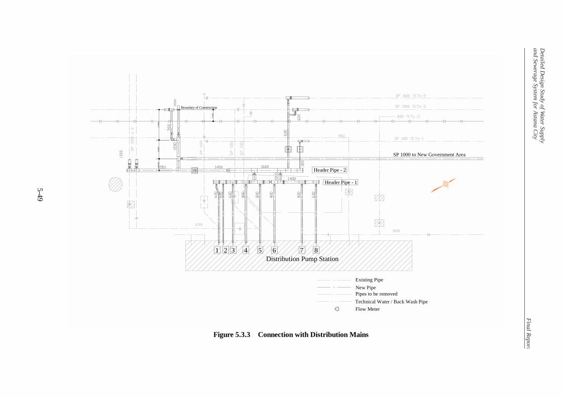
Detailed D
esign Study of Water Supply
and Sewerage System for Astana City
Final Repor t
5-49
Figure 5.3.3 Connection with Distribution Mains
SP 1000 to New Government Area
Boundary of Construction
Flow MeterTechnical Water / Back Wash PipePipes to be removedNew PipeExisting Pipe
Header Pipe - 1
Header Pipe - 2
1 2 3 4 5 6 7 8Distribution Pump Station


![Release 2.3.3[2.3.3[41142]] gns-mbh · 8 Presentation25 9 Indices and tables27 i. ii. Viewer, Release 2.3.3[2.3.3[41142]] TheAnimator4 Vieweris based on the kernel and the graphical](https://img.pdfslide.us/doc/110x75/5ed62916c021ad5e2d51d847/release-23323341142-gns-mbh-8-presentation25-9-indices-and-tables27-i-ii.jpg)