Embed Size (px)
Citation preview

Final Report: Improved Solar Cooking Unit for Use in Third World Countries
Kathryn Belisle John Karl Cameron Kennedy Joshua Vos
Submittal Date: 6/4/2007

1
Table of Contents
List of Figures.............................................................................................................................2
List of Tables ..............................................................................................................................2
Introduction ................................................................................................................................3
Problem Statement/Design Specifications: ..................................................................................3
Solar Heat Testing Procedure ......................................................................................................6
Solar Heat Testing Results ..........................................................................................................7
Bag Durability Testing Procedure .............................................................................................15
Bag Durability Testing Results..................................................................................................16
Longevity Testing .....................................................................................................................16
Material Strength Testing ..........................................................................................................16
Material Acquisition..................................................................................................................23
Manufacturing Considerations...................................................................................................23
Material Costs Analysis.............................................................................................................25
Future Improvements ................................................................................................................25
References ................................................................................................................................27
Appendix ..................................................................................................................................28

2
List of Figures
Figure 1: Test 1 ...........................................................................................................................8
Figure 2: Test 4 .........................................................................................................................10
Figure 3: Test 3 .........................................................................................................................12
Figure 4: Test 4 .........................................................................................................................13
Figure 5: Test 5 .........................................................................................................................15
Figure 6: Material and Fold Comparison for Perpendicular Corrugation Orientation .................18
Figure 7: Material and Fold Comparison for Parallel Corrugation Orientation ...........................19
Figure 8: Corrugation Orientation Comparison for All Materials with Break Press Fold............20
Figure 9: Average Force Comparison for Varying Fold Numbers ..............................................22
Figure 10: A drawing that was submitted in the patent from Mills Industries [1] ......................24
Figure 11: The Econolite® product photo [2] ............................................................................26
List of Tables Table 1: TEST 1 4/17/07. 5 mm Plastic (Bag) vs. Cardboard (Bag)……………………………...8
Table 2: TEST 2 5/1/07. 5 mm Plastic (PFA) vs. Cardboard (Bag) …………………………….10
Table 3: TEST 3 (5/8/07). 5 mm Plastic (Bag) vs. Cardboard (Bag)……………………………11
Table 4: TEST 4 (5/15/07). 3 mm Plastic (Bag) vs. Cardboard (Bag)…………………………..13
Table 5: TEST 5 (5/22/07). 3 mm Plastic (Bag) vs. 5 mm Plastic (Bag)………………………..14

3
Introduction
Currently in third world countries, a task as simple as cooking has important
consequences. Indoor pollution issues and scarcity of available firewood present dangers as well
as obstacles. One solution to these cooking issues is the use of solar energy for food preparation.
One solar cooking unit currently in use is a cardboard panel cooker called the CooKit.
Although it is an effective design, the CooKit has certain flaws that could be improved in
a new design. We propose to design a solar cooker to improve upon and replace the CooKit
model currently found in many homes in third world countries. Specifically, corrugated plastic
will be investigated as a replacement material for cardboard. We are focusing on seven main
criteria for the design including cost, cooking efficiency, portability, structural stability, water
resistance, ease of use, and aesthetics. By focusing on these criteria, we will address flaws in the
CooKit design while maintaining its optimal characteristics.
Problem Statement/Design Specifications:
The interior surface of the design must achieve an acceptable measure of reflectivity.
The device itself must be portable both for shipping to the customer and for transport by the user.
Though low weight must be maintained for portability, the design must be capable of
withstanding the force of wind. The design must also incorporate water resistance such that it
will not be destroyed by rain or heavy dew. The device must be easy to set up and take down as
well as to use. It is preferable that these basic tasks be explicable via simple pictorial
instructions only. Finally, the design must be low cost but should still be as aesthetically
pleasing as possible.
On February 15, 2007, we received word from Dr. Dale Andreatta that the current
CooKit is no longer being produced. Solar Cookers International lost their source for reflective

4
cardboard material when the company that produced this material went out of business. We have
since learned that Solar Cookers International is now heavily considering the use of corrugated
plastic in their replacement unit. This development represents an opportunity for our project to
have an immediate real-world impact provided we develop a successful design.
Fold Methods
Last quarter we experimented with the corrugated plastic in order to understand various
methods of folding. Specifically, we considered three methods: hand folding, folding with the
aid of a break press, and folding with the aid of partial cutting. The first method tested, hand
folding, proved to be the most infeasible. This method required the most effort while also
making it difficult to precisely adhere to desired fold lines. These problems were magnified if
the desired fold was not in the same direction as the corrugations in the material. Furthermore,
once made, the fold was not very strong and the material tended to return to its initial form. This
spring like action would result in a considerable decrease in the portability of our design.
The next method tested was folding with the aid of a break press. A significant
improvement over hand folding was observed, but this technique is still not ideal. The
corrugations were more compressed versus hand folding and folds could be easily made against
the grain of the corrugations. However, the material still had a strong tendency to return to its
initial form.
The final method tested last quarter was a partial cut folding technique. This method
involved cutting through one surface and the corrugations of the corrugated plastic leaving only
the second surface of the material fully intact. This cut allows the material to fold in the
direction of the uncut surface. This method was selected for our 5mm design because cutting the
material prior to folding allowed for very precise fold lines based on the precision of the cut.
5
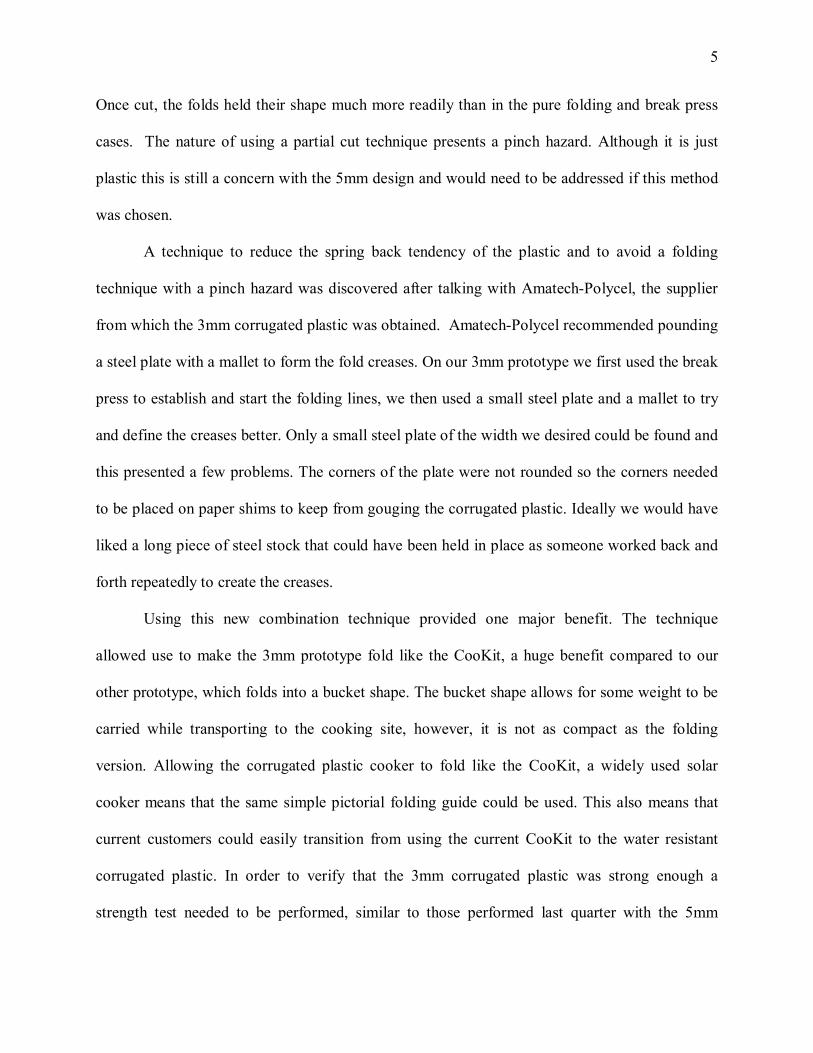
Once cut, the folds held their shape much more readily than in the pure folding and break press
cases. The nature of using a partial cut technique presents a pinch hazard. Although it is just
plastic this is still a concern with the 5mm design and would need to be addressed if this method
was chosen.
A technique to reduce the spring back tendency of the plastic and to avoid a folding
technique with a pinch hazard was discovered after talking with Amatech-Polycel, the supplier
from which the 3mm corrugated plastic was obtained. Amatech-Polycel recommended pounding
a steel plate with a mallet to form the fold creases. On our 3mm prototype we first used the break
press to establish and start the folding lines, we then used a small steel plate and a mallet to try
and define the creases better. Only a small steel plate of the width we desired could be found and
this presented a few problems. The corners of the plate were not rounded so the corners needed
to be placed on paper shims to keep from gouging the corrugated plastic. Ideally we would have
liked a long piece of steel stock that could have been held in place as someone worked back and
forth repeatedly to create the creases.
Using this new combination technique provided one major benefit. The technique
allowed use to make the 3mm prototype fold like the CooKit, a huge benefit compared to our
other prototype, which folds into a bucket shape. The bucket shape allows for some weight to be
carried while transporting to the cooking site, however, it is not as compact as the folding
version. Allowing the corrugated plastic cooker to fold like the CooKit, a widely used solar
cooker means that the same simple pictorial folding guide could be used. This also means that
current customers could easily transition from using the current CooKit to the water resistant
corrugated plastic. In order to verify that the 3mm corrugated plastic was strong enough a
strength test needed to be performed, similar to those performed last quarter with the 5mm

6
design. Sample test pieces of 1”×2” were made so that the corrugations would be perpendicular
with the pulling direction of the Instron machine. The results of this test and more detail about
the testing procedure can be seen in the “Material Strength Testing” section of this report.
Solar Heat Testing Procedure
One of the most important tests we ran this quarter was the solar heating test. This test
was very important because the experiment exactly replicated how the solar cookers would be
used in the third world countries they are intended for. This test was conducted multiple times
throughout the quarter with slight variations each time. However, the overall procedure
remained the same. All of these tests were conducted over a matter of hours at SEA Limited in
Columbus, Ohio, where Dr. Dale Andreatta was gracious enough to take data readings
throughout the experiment. We went to the site for each test in order to set it up and take the
initial readings, and Dr. Andreatta took any additional readings after that. He then sent us the
results at the conclusion of the test.
The testing procedure involved two solar cookers, two black pots, two covers, clips, zip
ties, a voltmeter, a pyranometer, thermocouples, and heat resistant tape. We started by taping a
thermocouple to the center of each of the two pots, elevated one inch from the bottom of the pot.
Next one of the empty pots was weighed to be 386.2 grams using a standard gram scale. We
then filled the pot with just enough water to fully submerge the thermocouple and weighed it
once again. The other empty pot was then placed onto the gram scale and water was added until
both pots reported the same weight. The two solar cookers being tested were then set up side by
side on a picnic table located at a corner of the building. This location offered full exposure to
the sun while also partially acting as a shield to the wind. Clips were used to hold the cookers in
position. The water-filled pots were then carefully placed into their covers and zip-tied shut with

7
only the thermocouple leads sticking out of the bag. In the experiment involving a tight PFA
cover, the bag edges were wrapped underneath the pots rather than being zip-tied shut. The pots
were then carefully placed in the center of their respective cookers. A minute or so was then
allowed to pass before the initial temperature readings were taken. During this time, the
pyranometer was used in conjunction with the voltmeter in order to measure the intensity of the
sun. This was simply done to show how peak water temperatures related to peak sun intensity.
Once the intensity was recorded, the thermocouple leads were attached to the voltmeter and the
temperature was recorded. The rest of the experiment consisted of simply checking the set-up a
number of times during the next few hours and reattaching the thermocouple leads to the
voltmeter in order to record the temperature. Usually the picnic table had to be rotated once
during the experiment in order to have the cookers facing the sun. In order to compare the
cookers being tested and draw conclusions, tables and graphs were generated based on the
experimental results.
Solar Heat Testing Results
The first test conducted using the procedure explained above took place on April 17th,
2007. For this initial test we compared the standard cardboard CooKit to the 5mm thick
corrugated plastic prototype we developed last quarter in ME 564. Pots were covered with the
standard plastic bags in both cases. Although last quarter’s reflectivity testing showed the two
should perform at a similar level, the solar heat test is a much more reliable testing method
because it occurs over a few hours rather than a few minutes. The results of this test are
tabulated in Table 1 and shown graphically in Figure 1.

8
5 mm Plastic (Bag) vs. Cardboard (Bag)
0
10
20
30
40
50
60
70
80
90
100
9:30 10:42 11:54 13:06 14:18 15:30 16:42
Time (EST)
Tem
pera
ture
(deg
C)
Plastic Temperature (deg C)
Cardboard Temperature (deg C)
Figure 1: Test 1
Table 1: TEST 1 4/17/07. 5 mm Plastic (Bag) vs. Cardboard (Bag)
Time Plastic Temperature (deg C)
Cardboard Temperature (deg C)
Air Temperature (deg C) Weather
10:13 21.4 22.9 Strong sun, strong wind
11:29 38.6 39.9 Strong sun, strong wind
12:54 69 69.1 Strong sun, strong wind
14:03 77.7 82.5 15 Strong sun, strong wind
14:51 85.2 89.5 Strong sun, strong wind
15:30 85.3 92.3 Strong sun Note: Units rotated at 14:03

9
The first thing to note about this test was that it strayed from the given procedure in a
couple ways since it was the first test conducted. Rather than using just enough water to
submerge the thermocouples, a full two-liter bottle was used in both pots. The gram scale
method was used in later experiments because less water is more typical of how these cookers
would actually be used. Also, the pyranometer was not available and thus was not used in this
initial test.
As far as the physical results, the first few readings are very similar to one another,
indicating that the reflectivity of the aluminum foil used in our prototype is very similar to that of
the aluminized cardboard material used in the CooKit. Over the last few readings when the sun
was lower in the sky, the CooKit outperformed the plastic prototype. After further testing and
analysis, we would eventually conclude that the reason for this is that the front panel of our
prototype stuck up slightly higher than the front panel on the CooKit. Although it was not
drastic enough to block the suns rays completely, it was enough to reflect some of the rays away
from the pot rather than directly at it. Further, upon breaking down the experiment it was
noticed that the thermocouple in the plastic cooker’s pot had come loose, possibly altering the
location where the reading was taken. This may have affected results.
Test number two was conducted on May 1st, 2007. For this test we used the same two
cookers as the first test. The difference was that this time we replaced the standard bag with a
tight PFA plastic cover for the pot contained within the plastic prototype. We continued to use a
standard plastic bag with the CooKit. The tight PFA plastic cover adds thermal benefits by
allowing for more sunrays to be trapped within the cover and thus be directed at the pot. The
goal of the experiment was to see if the added thermal benefits of the tight cover would allow the
more durable plastic cooker to perform as well as the standard CooKit and standard bag

10
technology currently in use. The results are tabulated in Table 2 and shown graphically in Figure
2.
Table 2: TEST 2 5/1/07. 5 mm Plastic (PFA) vs. Cardboard (Bag)
Time Plastic Temperature (deg C)
Cardboard Temperature (deg C)
Sunlight Intensity (mV) Weather
10:24 21 23 60 Mostly clear, light wind
11:27 57 58 76 Mostly clear, moderate wind
12:24 74 75 85 Mostly clear, moderate wind
13:15 87 83 90.3 Mostly clear, moderate wind
16:39 65 59 52 Hazy sun, strong wind Note: Units rotated at 13:18
5 mm Plastic (PFA) vs. Cardboard (Bag)
0
10
20
30
40
50
60
70
80
90
100
9:30 10:42 11:54 13:06 14:18 15:30 16:42 17:54
Time (EST)
Tem
pera
ture
(deg
C)
Plastic Temperature (deg C)Cardboard Temperature (deg C)
Figure 2: Test 4

11
The results showed that the plastic prototype along with the tight cover outperformed the
standard CooKit with a loose plastic bag. Much more condensation was observed within the
loose bag as opposed to the tight PFA cover during testing. This test proved that the plastic
design has the ability to perform to an acceptable level in the field.
Our third test was conducted on May 8th, 2007 and was simply a repeat of test number
one. As was noted earlier, the procedure for test one strayed slightly from the procedure we
wished to use and the thermocouple came loose during that experiment. We wanted to make
sure the results we obtained from test one were not due to outside factors such as these. The
results of test three are shown below in Table 3 and Figure 3.
Table 3: TEST 3 (5/8/07). 5 mm Plastic (Bag) vs. Cardboard (Bag)
Time Plastic Temperature (deg C)
Cardboard Temperature (deg C)
Sunlight Intensity (mV) Weather
10:44 17 22 68.9 Strong sun, no wind
12:07 55 61 57 Thin clouds
13:25 72.5 77 88.8 Clear sky, light wind
14:51 85 91 79.5 Clear sky, light wind
15:38 85 90 72 Clear sky, light wind

12
5 mm Plastic (Bag) vs. Cardboard (Bag)
0
10
20
30
40
50
60
70
80
90
100
9:30 10:42 11:54 13:06 14:18 15:30 16:42
Time (EST)
Tem
pera
ture
(deg
C)
Plastic Temperature (deg C)Cardboard Temperature (deg C)
Figure 3: Test 3 The results of the third test were similar to the first one. The cardboard CooKit once
again outperformed the plastic prototype. This would further lead us to believe the difference
could be attributed to slight variance in the front panel on the plastic prototype. We would
attempt to further investigate and fix this variance in future tests. Possible alteration of results in
test one due to the movement of the thermocouple was ruled out following test three since its
results were similar to test one.
For the fourth test, conducted on May 15th, 2007, we tested out a new plastic prototype.
This prototype was made of a thinner corrugated plastic (3 mm vs. 5 mm) and was crudely
folded as opposed to cut like the previous prototype. We paid more attention when shaping the
front panel on this prototype since we suspected that we had some issues with this panel on the

13
previous prototype. We set this test up similar to tests one and three. Both cookers had the
standard plastic bag. The results are shown as Table 4 and Figure 4.
Table 4: TEST 4 (5/15/07). 3 mm Plastic (Bag) vs. Cardboard (Bag)
Time Plastic Temperature (deg C)
Cardboard Temperature (deg C)
Sunlight Intensity (mV) Weather
10:45 22 23 62 Strong sun, strong wind 12:15 66 67 85 Strong sun, strong wind 13:07 79 76 90 Strong sun, strong wind 14:13 83 80 87.5 Mostly sunny, strong wind 15:08 88 80 86 Mostly sunny, strong wind
15:37 86 79 20.4 Sun behind thick cloud, strong wind
Note: Units rotated at 13:07
3 mm Plastic (Bag) vs. Cardboard (Bag)
0
10
20
30
40
50
60
70
80
90
100
9:30 10:42 11:54 13:06 14:18 15:30 16:42
Time (EST)
Tem
pera
ture
(deg
C)
Plastic Temperature (deg C)Cardboard Temperature (deg C)
Figure 4: Test 4

14
The results of this test were very positive. The folded plastic prototype outperformed the
cardboard CooKit without the need to use the tight PFA cover. The theory of the poor front
panel on the previous prototype gained momentum as the increased performance of the thinner
prototype probably resulted from the smaller and more accurate front panel it contained.
The fifth and final test we conducted this quarter for solar heating purposes were
conducted on May 22nd, 2007. For this test we compared the new thinner plastic prototype to the
older thicker plastic prototype, both using loose bags. Our expectation based on previous testing
was that the thinner prototype would outperform the thicker prototype. A result like this would
further show that test four was accurate. The results are shown as Table 5 and Figure 5.
Table 5: TEST 5 (5/22/07). 3 mm Plastic (Bag) vs. 5 mm Plastic (Bag)
Time 3 mm Temperature (deg C)
5 mm Temperature (deg C)
Sunlight Intensity (mV) Weather
11:03 17 16 71 Strong sun, no wind
12:23 50 48 85 Strong sun, light wind
13:32 72 68 98.5 Mostly sunny, light wind
14:39 74 72 96 Partly cloudy, light wind
15:29 71 67 86.5 Partly cloudy, light wind

15
3 mm Plastic (Bag) vs. 5 mm Plastic (Bag)
0
10
20
30
40
50
60
70
80
9:30 10:42 11:54 13:06 14:18 15:30 16:42
Time (EST)
Tem
pera
ture
(deg
C)
3 mm Temperature (deg C)5 mm Temperature (deg C)
Figure 5: Test 5 The results of this test met our expectations. The thinner prototype outperformed the
thicker prototype. The results of all five tests lead us to conclude that the plastic prototype can
perform just as well as, if not better than, the cardboard CooKit. An oversized front panel
hindered our first prototype, but we were able to correct this with our second prototype.
Bag Durability Testing Procedure
In addition to the solar cooker structure, we decided to expand our analysis and assist Dr.
Andreatta in testing bag materials. In order to conduct long term bag material durability testing,
we constructed a large reflector out of corrugated plastic and aluminum foil. This reflector is
large enough to house two bags containing pots as well as an additional bag. It is simply a large
rectangle that is folded in the middle in order to direct more sunlight onto the bags than would be
seen normally. The reflector is designed to be placed outdoors for a long period of time in order
to observe how well the different bags stand up to constant sunlight.
16
Bag Durability Testing Results
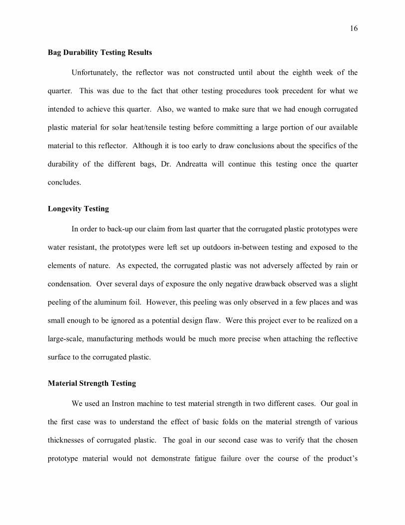
Unfortunately, the reflector was not constructed until about the eighth week of the
quarter. This was due to the fact that other testing procedures took precedent for what we
intended to achieve this quarter. Also, we wanted to make sure that we had enough corrugated
plastic material for solar heat/tensile testing before committing a large portion of our available
material to this reflector. Although it is too early to draw conclusions about the specifics of the
durability of the different bags, Dr. Andreatta will continue this testing once the quarter
concludes.
Longevity Testing
In order to back-up our claim from last quarter that the corrugated plastic prototypes were
water resistant, the prototypes were left set up outdoors in-between testing and exposed to the
elements of nature. As expected, the corrugated plastic was not adversely affected by rain or
condensation. Over several days of exposure the only negative drawback observed was a slight
peeling of the aluminum foil. However, this peeling was only observed in a few places and was
small enough to be ignored as a potential design flaw. Were this project ever to be realized on a
large-scale, manufacturing methods would be much more precise when attaching the reflective
surface to the corrugated plastic.
Material Strength Testing
We used an Instron machine to test material strength in two different cases. Our goal in
the first case was to understand the effect of basic folds on the material strength of various
thicknesses of corrugated plastic. The goal in our second case was to verify that the chosen
prototype material would not demonstrate fatigue failure over the course of the product’s

17
lifetime. We used the same basic testing method in both cases. We used samples that were
approximately two by one inches for all material strength testing. Once the samples were
prepared, we placed each in the Instron clamps such that the edges of the clamps were close to
the portion to be tested, in other words the fold line. We set the Instron to a speed of 25 samples
per second in high gear. Labview was used to obtain the applied force, in pounds force, as
related to the sample number.
Though the setup was the same in both cases, the sample preparation was vastly different.
In the first case, we wanted to generate a comparison between the strengths of corrugated plastic
of different thicknesses at a fold line. Thus, in this case, we prepared samples from each of the
three material thicknesses including thin (2 mm), mid (3 mm), and thick (5 mm). Since we new
that the orientation of the corrugations would affect the strength, samples were made for each
material in the two extreme orientations of the corrugations (parallel and perpendicular) as
compared to the fold line. Most importantly, we needed to consider the different potential fold
methods. These methods include a plain fold generated using a break press or other method and
a partial cut fold in which one plain of the plastic sheet is cut leaving the other plain intact.
Thus, samples were generated for each of the three material thicknesses using the two different
fold methods in each corrugation orientation.

18
Figure 6: Material and Fold Comparison for Perpendicular Corrugation Orientation
Figure 1 is a comparison between the different folding methods used on each of the three
material widths when the corrugations were oriented perpendicular to the fold line. The solid
line in each color shows the strength of the material when the sample was folded using the break
press. The dashed line in each color shows the strength of the material when the material was
partially cut. The dotted line in each color shows the strength of the material when some other
fold method was used or when a sample was repeated. The data shows that the partial cut
technique resulted in a lower strength than the partial cut method for all three materials, as
expected. The data also shows that all three materials performed at approximately the same
strength level when the partial cut technique was used. We expected this result as well since all
three sheets are made of the same type of plastic. However, the material thickness appears to be

19
proportionate to the strength when the break press folding technique is used. Thus, the thick
material showed the highest results followed by the mid material and then the thin material.
Figure 7: Material and Fold Comparison for Parallel Corrugation Orientation
Figure 2 shows similar results to those of Figure 1 when the fold line is in parallel with
the corrugations. The strength for the break press fold technique is again proportionate to the
thickness of the material. There were greater discrepancies between the materials and fold
methods in this fold direction. This is most likely due to variations in the placement of the
clamps on each sample. Though we tried to position the clamps close to the fold line, the
corrugations close to the fold line provided weak points other than the fold line. Thus, many of
the samples gave way between corrugations at random and not necessarily at the fold line as in
the case when the fold line was perpendicular to the corrugations.

20
Figure 8: Corrugation Orientation Comparison for All Materials with Break Press Fold
Figure 3 shows a comparison between the fold line directions for the break press folding
method used on each material. The red lines denote the parallel direction and the blue lines
denote the perpendicular direction. As expected, the corrugations have a strengthening effect on
all materials when they are perpendicular to the fold line. The added strength is approximately
proportionate to the thickness of the material (in other words to the width of the corrugations).
Despite the weakening effect of the parallel corrugation orientation, all three materials
demonstrate more than enough strength for the desired application regardless of corrugation
orientation.
In the fold fatigue testing, the samples were generated under vastly different
considerations. First, we chose to only test the mid thickness (3 mm) material because this was
our recommendation for an optimal design material. We also chose to create all the samples
21
with the same corrugation orientation. The horizontal orientation was selected based on the
previous tests that showed this to be the weaker of the two orientations. We created nine
samples of approximately the same size. Each was first folded approximately in the center in the
same orientation as the corrugations using the break press. Four samples were folded 250 times
and another four samples were folded 500 times. The ninth sample was folded 1000 times. We
chose to fold 500 times by conservatively estimating the number of times the unit would be
folded over its lifetime. This estimate was based on our background knowledge of the previous
products use as well as the expected climate and seasonal weather patterns of the target market.
We chose to test a sample folded 1000 times in the event that our estimates of the products life
should be wrong. We felt that if this sample showed a rapid decrease in strength we would need
to verify our estimations and possibly complete further testing at higher fold numbers. We also
tested at 250 folds to illustrate a full array of data for comparison should any important trends
arise.

22
Figure 9: Average Force Comparison for Varying Fold Numbers
Figure 4 illustrates the averaged results of the fold fatigue testing. The red line represents
250 folds, the green line 500 folds, and the blue line 1000 folds. All three fold sample numbers
resulted in acceptable strength values. No reduction in strength was found in the 1000 fold
sample, which actually performed at a higher level than the other two sample sets. While this
increased performance could be a fluke, we felt it obvious that the 1000 folds had not in any way
weakened the material. Thus, we concluded that the material we selected for the design is
resilient and fatiguing at fold lines over prolonged product use will not be an issue.

23
Material Acquisition
One of the most important responsibilities this quarter was to test several different
thicknesses of corrugated plastic to determine which performed optimally. The three different
thickness samples tested were the 2mm, 3mm, and 5mm. Having already been provided the 5
mm thickness (last quarter’s prototype) by Dr. Dale Andreatta, the 2 other thicknesses had to be
acquired in order to do comparative reflective and strength testing.
After researching and asking Dr. Andreatta if he knew of a good supplier, we
encountered a company by the name of Amatech-Polycel located locally in Columbus, Ohio.
The local company was a reliable source and had the two thicknesses we intended to test
available. We wanted to obtain plastic sheets that were white in color, however, black was the
only color in which they had in stock. The white sheets could be obtained by ordering from the
Erie, Pennsylvania site, however, this was not necessary for our prototype. After contacting
Amatech-Polycel for the plastic, we were fortunate enough to be given the materials free of
charge. This made for low budget prototype testing this quarter.
Another sheet of black 5mm thickness material was obtained from another supplier in
Columbus called American Plastic Distributors. This material was taken from their scrap
inventory and was purchased for less than a dollar. The small scrap piece of plastic was used to
do strength testing after the original material supplied by Dr. Andreatta was depleted. We felt
that the 5mm plastics from Dr. Andreatta and from American Plastic Distributors were very
comparable to each other, thus the strength would not vary much.
Manufacturing Considerations
One of the major manufacturing considerations, aside from the process of cutting the
plastic to shape, was the folding process. Several methods of folding the corrugated plastic were

24
looked at throughout this project to determine which would be the most feasible method. As
explained earlier, the straight fold method allowed the prototype to be fold exactly like the
CooKit. This folding technique could be accomplished in the manufacturing process with two
possible solutions.
Researching online led us to a patent for a “method and apparatus for heavy corrugated
plastic construction” (patent # 6056840) designated to a company called Mills Industries Inc.
from New Hampshire. The process involves heating a metal blade, which is then pressed into
the plastic. This process creates fold-lines with adherable sides that can be used to hold the
corners of a box shaped container. A cooling process of the plastic would allow this process to
be useful in creating a panel cooker that we need. Once cooled, the surfaces would not be
permanently attached to one another, thus allowing them to be folded together.
Figure 10: A drawing that was submitted in the patent from Mills Industries [1]

25
In our discussions with Amatech-Polycel we learned about a process they use to fold their
products into shape utilizing a clipper-die press. The clipper-die press used by Amatech-Polycel
and the process that Mills Industries used is very similar.
Material Costs Analysis
Although the materials obtained from Amatech-Polycel were free of charge, we were
able to receive some price quotes on the material. We found the 3 mm material to be priced at
$0.21/ft2. This price was very similar to that of the price quote that Dr. Andreatta heard though
word of mouth. Another material we were looking at was called Econolite®. This material
already has an aluminum surface baked into the side of the corrugated plastic with a lamination
process. This material would be easier to implement and would optimize our prototype.
However, in light of cutting costs and providing a relatively inexpensive product, this material
did not meet the standards we were looking for. Quoted at $2.89/ft2, this material was much
more expensive than normal corrugated plastic and would be too expensive to use for our
prototype. We concluded that the technology to further optimize our product is available, but
due to its extreme costs it is currently not feasible.
Future Improvements
Based on testing results from this quarter further optimization of the product could be
done. The aluminum foil did not hold up very well in the durability testing. A better application
of the aluminum covering or another aluminizing process should be looked into. We also
researched possible proprietary processes that could produce the material we were looking for.

26
After researching we found a material now as Econolite® distributed by Meyers Plastics
in Indianapolis, Indiana that was available in a 6 mm thickness that was white in color with a
painted on aluminum surface on one side. After contacting Meyers Plastics, we were able to
learn a small bit about the manufacturing process and received some price quotes. Econolite® is
created by mixing and adhesive additive into an aluminum paint that is baked onto a sheet of
corrugated plastic in a lamination process that seals and protects the surface. It was quoted at
$2.89/ft2, a price well beyond a feasible material for this third world project.
Figure 11: The Econolite® product photo [2]

27
References [1] Mills, Michael. "Method and apparatus for heavy corrugated plastic construction." Google
Patents. 05/02/2000. 31 May 2007
<http://www.google.com/patents?id=1oADAAAAEBAJ&dq=6056840>.
[2] “Corrugated Plastic Center Materials.” 30 May 2007
<http://www.meyerplastics.com/signandgraphics/corrugated_plastic_center_materi.htm>

28
Appendix
Gantt Chart:
Figure 12: SP07 Gantt Chart